Embed Size (px)
Citation preview
33
▼ PL-1.0
▼ PL-1.0HV
▼ PL-1.4
▼ PL-1.5X
▼ PL-1.6HVX
▼ PL-1.8
▼ PL-2.0HV
▼ PL-2.4MB
P o w e r L i g h t ™
S e r i e sTD-000063-00Rev. C
User Manual
Manuel de l’utilisateur
Bedienhandbuch
Manual del Usuario
TD-000063-00

1
Turn-on/turn-off muting .................................... 24Mise en sourdine lors de la mise sous/hors tensionStummschaltung bei An- und AusschaltenEnmudecimiento de encendido/apagado
Short circuit protection .................................... 24Protection contre les court-circuitsSchutz bei KurzschlußProtección contra corto-circuito
Clip limiting ........................................................ 24Limiteur d'écrêtementÜbersteuerungsbegrenzungLimitando clips
Thermal protection ........................................... 25Protection thermiqueThermische SchutzschaltungProtección térmica
DC fault protection ........................................... 25Protection contre une anomalie CCSchutz gegen GleichspannungProtección contra corriente continua
Input/output protection ..................................... 25Protection entrées/sortiesEingangs-/AusgangsschutzProtección entrada/salida
SPECIFICATIONS ............................................... 26SPÉCIFICATIONSTECHNISCHE DATENESPECIFICACIONES
WARRANTY INFORMATION ............................ 30INFORMATIONS DE GARANTIEGARANTIEBEDINGUNGENINFORMACIÓN DE GARANTÍA
ADDRESS &TELEPHONE INFORMATION ............................. 31
ADRESSE POSTALE ET NUMÉROSANSCHRIFT UND TELEFONNUMMERNDIRECCIÓN Y TELÉFONO
Explanation of graphical symbols ................... 2Explication des symboles graphiquesErklärung der BildsymboleExplicación de símbolos
FCC Interference Statement .............................. 3
INTRODUCTION ................................................... 5AVANT-PROPOSEINFÜHRUNGINTRODUCCIÓN
Front panel ............................................................ 6Panneau avantVorderseitePanel frontal
Rear panel ............................................................ 7Panneau arrièreRückseitePanel posterior
MOUNTING ........................................................... 8MONTAGEBEFESTIGUNGMONTAJE
Front ....................................................................... 8AvantVornFrente
Rear ....................................................................... 9ArrièreHintenTrasera
Operating voltage (AC mains) ........................ 10Tension d’utilisation (alimentation CA)Netz-BetriebspannungVoltaje de funcionamiento (CA)
Inputs ................................................................... 10EntréesEingängeEntradas
Data Port ............................................................. 11Port de donnéesData PortPuerto de datos
Outputs ................................................................ 11SortiesAusgängeSalidas
Speaker cabling ................................................ 12Câblage du haut-parleurLautsprecherkabelCableado de bocinas
OPERATION ......................................................... 13FONCTIONNEMENTBETRIEBOPERACIÓN
Gain controls ...................................................... 13Commandes de gainPegelstellerControles de ganancia
Remote power supply control ......................... 13Télécommande du bloc d’alimentationFerneinschaltungControl remoto de alimentación
Clip limiter .......................................................... 14Limiteur d'écrêtementClip-LimiterLimitador anti-clip
LED indicators .................................................... 15Indicateurs DELLED-AnzeigenIndicadores LED
Parallel, stereo, and bridged mono ............... 16Modes parallèle, stéreo, et mono ponté (bridgé)Stereobetrieb, Eingangsparallelschaltung, und Mono-BrückenbetriebParalelo, estéreo, y mono puente
Using the PowerLight 1.5X and 1.6HVX ........................ 20Utilisation des PowerLight 1.5X et 1.6HVX
Benutzung der PowerLight 1.5X und1.6HVX
Uso del PowerLight 1.5X y 1.6HVX
Using the PowerLight 2.4MB .................................................... 22Utilisation du PowerLight 2.4MB
Benutzung der PowerLight 2.4MB EndstufeUso del PowerLight 2.4MB
PROTECTION ...................................................... 24PROTECTIONSCHUTZSCHALTUNGENPROTECCIÓN
T A B L E O F C O N T E N T S ▼ TA B L E D E S M AT I È R E S ▼ I N H A LT S V E R Z E I C H N I S ▼ TA B L A D E L A S M AT E R I A S
2
Erklärung derBildsymbole
Das Blitzzeichen innerhalb eines
gleichseitigen Dreiecks warnt den
Benutzer vor nicht-isolierter,
gefährlicher Spannung im Inneren
des Gerätes. Diese Spannung ist
hoch genug, um Personen durch
elektrischen Schlag zu gefährden.
Das Ausrufungszeichen innerhalb
eines gleichseitigen Dreiecks weist
den Benutzer auf wichtige
Bedienungs- und
Wartungsanweisungen hin, die in
den gerätebegleitenden Unterlagen
aufgeführt sind.
Explicación desímbolos
El rayo inscrito en un tríangulo
equilátero alerta al usuario de la
presencia de voltaje peligroso no
aislado dentro del producto, que
pude ser de nivel suficiente como
para constitutuir riesgo de descarga
eléctrica para las personas.
El signo de exclamación inscrito en
un triángulo equilátero alerta a los
usuarios de la presencia de
instrucciones importantes de
funcionamiento y mantenimiento
(servicio) en el manual que
acompaña al producto.
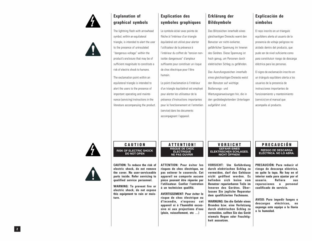
Explanation ofgraphical symbols
The lightning flash with arrowhead
symbol, within an equilateral
triangle, is intended to alert the user
to the presence of uninsulated
“dangerous voltage” within the
product’s enclosure that may be of
sufficient magnitude to constitute a
risk of electric shock to humans.
The exclamation point within an
equilateral triangle is intended to
alert the users to the presence of
important operating and mainte-
nance (servicing) instructions in the
literature accompanying the product.
Explication dessymboles graphiques
Le symbole éclair avec pointe de
flèche à l'intérieur d'un triangle
équilatéral est utilisé pour alerter
l'utilisateur de la présence à
l'intérieur du coffret de "tension non-
isolée dangereuse" d'ampleur
suffisante pour constituer un risque
de choc électrique pour l'être
humain.
Le point d'exclamation à l'intérieur
d'un triangle équilatéral est employé
pour alerter les utilisateur de la
présence d'instructions importantes
pour le fonctionnement et l'entretien
(service) dans les documents
accompagnant l'appareil.
CAUTION: To reduce the risk ofelectric shock, do not removethe cover. No user-serviceableparts inside. Refer servicing toqualified service personnel.
WARNING: To prevent fire orelectric shock, do not exposethis equipment to rain or mois-ture.
ATTENTION: Pour éviter lesrisques de choc électrique, nepas enlever le couvercle. Cetappareil ne comporte aucunepièce pouvant être réparée parl'utilisateur. Confier l'entretienà un technicien qualifié.
AVERTISSEMENT: Pour éviter lerisque de choc électrique oud'incendie, n'exposez cetappareil ni à l'humidité exces-sive ni aux projections d'eau(pluie, ruissellement, etc …)
VORSICHT: Um Gefährdungdurch elektrischen Schlag zuvermeiden, darf das Gehäusenicht geöffnet werden. Esbefinden sich keine vomBenutzer reparierbaren Teile imInneren des Gerätes. Über-lassen Sie jegliche Reparaturdem qualifizierten Fachmann.
WARNUNG: Um die Gefahr einesBrandes bzw. eine Verletzungdurch elektrischen Schlag zuvermeiden, sollten Sie das Gerätniemals Regen oder Feuchtig-keit aussetzen.
PRECAUCIÓN: Para reducir elriesgo de descarga eléctrica,no quite la tapa. No hay en elinterior nada para ajustar por elusuario. Refiera susreparaciones a personalcualificado de servicio.
AVISO: Para impedir fuegos odescargas eléctricas, noexponga este equipo a la lluviao la humedad.
C A U T I O NRISK OF ELECTRIC SHOCK
DO NOT OPEN
A T T E N T I O N !RISQUE DE CHOC
ÉLECTRIQUENE PAS OUVRIR
V O R S I C H TGEFAHR EINES
ELEKTRISCHEN SCHLAGES.NICHT ÖFFNEN!
P R E C A U C I Ó NRIESGO DE DESCARGA
ELÉCTRICA. NO LO ABRA.
3
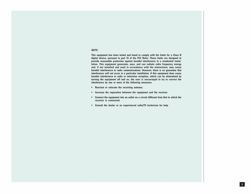
NOTE:
This equipment has been tested and found to comply with the limits for a Class Bdigital device, pursuant to part 15 of the FCC Rules. These limits are designed toprovide reasonable protection against harmful interference in a residential instal-lation. This equipment generates, uses, and can radiate radio frequency energyand, if not installed and used in accordance with the instructions, may causeharmful interference to radio communications. However, there is no guarantee thatinterference will not occur in a particular installation. If this equipment does causeharmful interference to radio or television reception, which can be determined byturning the equipment off and on, the user is encouraged to try to correct theinterference by one or more of the following measures:
• Reorient or relocate the receiving antenna.
• Increase the separation between the equipment and the receiver.
• Connect the equipment into an outlet on a circuit different from that to which thereceiver is connected.
• Consult the dealer or an experienced radio/TV technician for help.

4
© Copyright 1998, 2000 QSC Audio Products, Inc.
QSC® is a registered trademark, and PowerLight™ and MultiSignal Processor™ are trademarks, of QSC Audio Products, Inc.
“QSC” and the QSC logo are registered with the U.S. Patent and Trademark Office.
"Combo" is a trademark of Neutrik AG.
All other trademarks are the property of their respective owners.

5
I N T R O D U C T I O N E I N F Ü H R U N G I N T R O D U C C I Ó NA V A N T - P R O P O SThis manual covers these eight
PowerLight models. All are 2RU high
(3.5 inches, or 8.9 centimeters) and
weigh approximately 18 pounds (8.2
kilograms).
PowerLight 1.0 Two-channel
model; 500 watts/channel @ 2
ohms.
PowerLight 1.0HV "High-voltage"
two-channel model; 500 watts/
channel @ 4 ohms.
PowerLight 1.4 Two-channel
model; 700 watts/channel @ 2
ohms.
PowerLight 1.5X Bi-amp model; LF
channel: 1000 watts @ 2 ohms;
HF channel: 500 watts @ 2
ohms.
PowerLight 1.6HVX "High voltage"
bi-amp model; LF channel: 1100
watts @ 4 ohms; HF channel:
450 watts @ 4 ohms.
PowerLight 1.8 Two-channel
model; 900 watts/channel @ 2
ohms.
PowerLight 2.0HV "High-voltage"
two-channel model; 1000 watts/
channel @ 4 ohms.
PowerLight 2.4MB "Mono block"
single-channel model; 2400
watts @ 2 ohms.
Ce manuel traite des huit modèles
PowerLight ci-dessous. Ils occupent
chacun 2 espaces normalisés (3.5
pouces, ou 8.9 centimètres) et
pèsent approximativement 18 livres
(8.2 kilogrammes).
PowerLight 1.0 Modèle deux
canaux; 500 watts par canal @ 2
ohms.
PowerLight 1.0HV Modèle deux
canaux "haute tension"; 500
watts par canal @ 4 ohms.
PowerLight 1.4 Modèle deux
canaux; 700 watts par canal @ 2
ohms.
PowerLight 1.5X Modèle bi-
amplifié; canal LF: 1000 watts @
2 ohms; canal HF: 500 watts @ 2
ohms.
PowerLight 1.6HVX Modèle bi-
amplifié "haute tension"; canal
LF: 1100 watts @ 4 ohms; canal
HF: 450 watts @ 4 ohms.
PowerLight 1.8 Modèle deux
canaux; 900 watts par canal @ 2
ohms.
PowerLight 2.0HV Modèle deux
canaux "haute tension"; 1000
watts par canal @ 4 ohms.
PowerLight 2.4MB Modèle simple
canal "mono bloc"; 2400 watts
@ 2 ohms.
Este manual cubre estos ocho
modelos de amplificadores
PowerLight. Todos entran en dos
unidades de rack (3.5 pulgadas o 8.9
centímetros) y pesan aproximada-
mente 18 libras (8.2 kilos).
PowerLight 1.0 Modelo de dos
canales; 500 vatios por canal @
2 ohmios.
PowerLight 1.0HV Modelo "alto
voltaje" de dos canales; 500
vatios por canal @ 4 ohmios.
PowerLight 1.4 Modelo de dos
canales; 700 vatios por canal @
2 ohmios.
PowerLight 1.5X Modelo
biamplificado; canal de bajos
1000 vatios @ 2 ohmios; canal
de altos 500 vatios @ 2 ohmios.
PowerLight 1.6HVX Modelo "alto
voltaje" biamplificado; canal de
bajo 1000 vatios @ 4 ohmios;
canal de altos 450 vatios @ 4
ohmios.
PowerLight 1.8 Modelo de dos
canales, 900 vatios por canal @
2 ohmios.
PowerLight 2.0HV Modelo "alto
voltaje" de dos canales; 100
vatios por canal @ 4 ohmios.
PowerLight 2.4MB Modelo mono,
un solo canal de 2400 vatios @
2 ohmios.
Die Anleitung ist für acht
PowerLight-Verstärkertypen mit 2
Höheneinheiten (8,9 cm) und einem
Gewicht von ca. 8,2 kg.
PowerLight 1.0
Zweikanalverstärker, 500 W/
Kanal bei 2 Ohm
PowerLight 1.0HV „High Voltage“-
Zweikanalverstärker, 500 W/
Kanal an 4 Ohm
PowerLight 1.4
Zweikanalverstärker, 700 W/
Kanal an 2 Ohm
PowerLight 1.5X Bi-Amp-
Verstärker. Tieftonkanal 1000
W/2 Ohm, Hochton 500 W/2
Ohm.
PowerLight 1.6HVX „High Voltage“-
Bi-Amp-Verstärker. Tieftonkanal
1100 W/4 Ohm, Hochton 450
W/4 Ohm.
PowerLight 1.8
Zweikanalverstärker, 900 W/
Kanal an 2 Ohm
PowerLight 2.0HV „High-Voltage“-
Zweikanalverstärker, 1000 W/
Kanal an 4 Ohm.
PowerLight 2.4MB „Mono-Block“-
Einkanalverstärker. 2400 W/2
Ohm
6
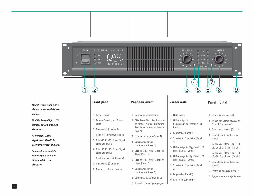
Front panel
1. Power switch
2. Protect, Standby, and PowerLEDs
3. Gain control (Channel 1)
4. Clip limiter switch (Channel 1)
5. Clip, -10 dB, -20 dB and SignalLEDs (Channel 1)
6. Clip, -10 dB, -20 dB and SignalLEDs (Channel 2)
7. Clip limiter switch (Channel 2)
8. Gain control (Channel 2)
9. Mounting holes for handles
Panel frontal
1. Interruptor de encendido
2. Indicadores LED de Protección,“Standby” y Operación
3. Control de ganancia (Canal 1)
4. Conmutador de limitador-clip(Canal 1)
5. Indicadores LED de “Clip,” -10dB, -20 dB y “Signal” (Canal 1)
6. Indicadores LED de “Clip,” -10dB, -20 dB y “Signal” (Canal 2)
7. Conmutador de limitador-clip(Canal 2)
8. Control de ganancia (Canal 2)
9. Agujeros para montaje de asas
Panneau avant
1. Commande marche/arrêt
2. DELs (Diode ElectroLuminescente)de modes Protect (protection),Standby (en attente), et Power (enfonction)
3. Commande de gain (Canal 1)
4. Sélecteur de limiteurd'écrêtement (Canal 1)
5. DELs de Clip, -10 dB, -20 dB, etSignal (Canal 1)
6. DELs de Clip, -10 dB, -20 dB, etSignal (Canal 2)
7. Sélecteur de limiteurd'écrêtement (Canal 2)
8. Commande de gain (Canal 2)
9. Trous de montage pour poignées
Vorderseite
1. Netzschalter
2. LED-Anzeige fürSchutzschaltung, Standby undBetrieb
3. Pegelsteller (Kanal 1)
4. Schalter für Clip-Limiter (Kanal1)
5. LED-Anzeige für Clip, -10 dB, -20dB und Signal (Kanal 1)
6. LED-Anzeige für Clip, -10 dB, -20dB und Signal (Kanal 2)
7. Schalter für Clip-Limiter (Kanal2)
8. Pegelsteller (Kanal 2)
9. Griffbefestigungslöcher
Model PowerLight 2.0HV
shown; other models are
similar.
Modèle PowerLight 2.0HV
montré; autres modèles
similaires.
PowerLight 2.0HV
abgebildet. Restliche
Verstärkertypen ähnlich.
Se muestra el modelo
PowerLight 2.0HV. Los
otros modelos son
similares.
7
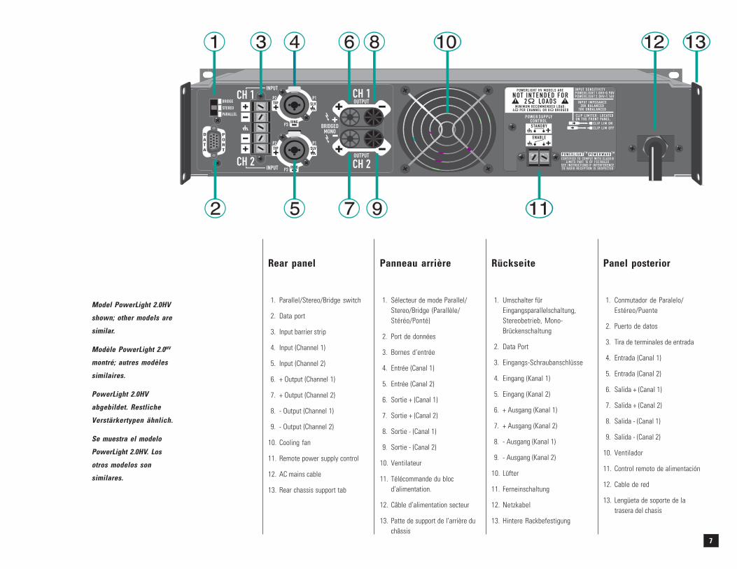
Rear panel
1. Parallel/Stereo/Bridge switch
2. Data port
3. Input barrier strip
4. Input (Channel 1)
5. Input (Channel 2)
6. + Output (Channel 1)
7. + Output (Channel 2)
8. - Output (Channel 1)
9. - Output (Channel 2)
10. Cooling fan
11. Remote power supply control
12. AC mains cable
13. Rear chassis support tab
Panneau arrière
1. Sélecteur de mode Parallel/Stereo/Bridge (Parallèle/Stéréo/Ponté)
2. Port de données
3. Bornes d’entrée
4. Entrée (Canal 1)
5. Entrée (Canal 2)
6. Sortie + (Canal 1)
7. Sortie + (Canal 2)
8. Sortie - (Canal 1)
9. Sortie - (Canal 2)
10. Ventilateur
11. Télécommande du blocd’alimentation.
12. Câble d’alimentation secteur
13. Patte de support de l’arrière duchâssis
Rückseite
1. Umschalter fürEingangsparallelschaltung,Stereobetrieb, Mono-Brückenschaltung
2. Data Port
3. Eingangs-Schraubanschlüsse
4. Eingang (Kanal 1)
5. Eingang (Kanal 2)
6. + Ausgang (Kanal 1)
7. + Ausgang (Kanal 2)
8. - Ausgang (Kanal 1)
9. - Ausgang (Kanal 2)
10. Lüfter
11. Ferneinschaltung
12. Netzkabel
13. Hintere Rackbefestigung
Panel posterior
1. Conmutador de Paralelo/Estéreo/Puente
2. Puerto de datos
3. Tira de terminales de entrada
4. Entrada (Canal 1)
5. Entrada (Canal 2)
6. Salida + (Canal 1)
7. Salida + (Canal 2)
8. Salida - (Canal 1)
9. Salida - (Canal 2)
10. Ventilador
11. Control remoto de alimentación
12. Cable de red
13. Lengüeta de soporte de latrasera del chasis
Model PowerLight 2.0HV
shown; other models are
similar.
Modèle PowerLight 2.0HV
montré; autres modèles
similaires.
PowerLight 2.0HV
abgebildet. Restliche
Verstärkertypen ähnlich.
Se muestra el modelo
PowerLight 2.0HV. Los
otros modelos son
similares.
8
M O N T A G E
Avant
Utiliser quatre vis de montage.
B E F E S T I G U N G
Vorn
Benutzen Sie vier
Befestigungsschrauben.
M O N T A J E
Frente
Utilice cuatro tornillos.
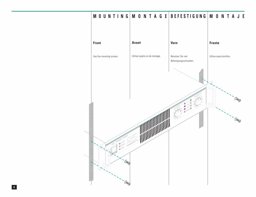
M O U N T I N G
Front
Use four mounting screws.
9
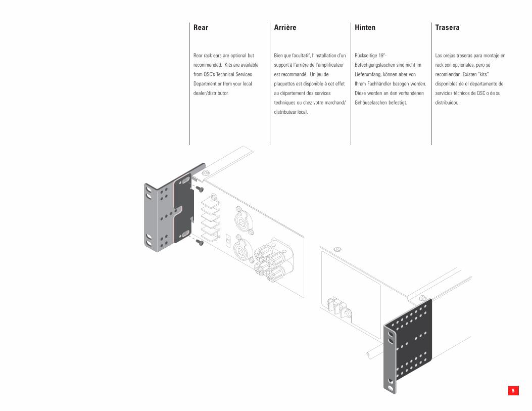
Rear
Rear rack ears are optional but
recommended. Kits are available
from QSC’s Technical Services
Department or from your local
dealer/distributor.
Arrière
Bien que facultatif, l’installation d’un
support à l’arrière de l’amplificateur
est recommandé. Un jeu de
plaquettes est disponible à cet effet
au département des services
techniques ou chez votre marchand/
distributeur local.
Hinten
Rückseitige 19"-
Befestigungslaschen sind nicht im
Lieferumfang, können aber von
Ihrem Fachhändler bezogen werden.
Diese werden an den vorhandenen
Gehäuselaschen befestigt.
Trasera
Las orejas traseras para montaje en
rack son opcionales, pero se
recomiendan. Existen “kits”
disponibles de el departamento de
servicios técnicos de QSC o de su
distribuidor.
10
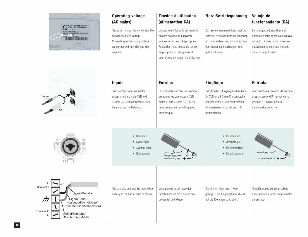
Operating voltage(AC mains)
The serial number label indicates the
correct AC mains voltage.
Connecting to the wrong voltage is
dangerous and may damage the
amplifier.
Tension d’utilisation(alimentation CA)
L’étiquette sur laquelle est inscrit le
numéro de série de l’appareil
indique la tension CA appropriée.
Raccorder à une source de tension
inappropriée est dangereux et
pourrait endommager l’amplificateur.
Netz-Betriebspannung
Das Seriennummernetikett zeigt die
korrekte zulässige Betriebsspannung
an. Eine andere Netzspannung kann
den Verstärker beschädigen und
gefährlich sein.
Voltaje defuncionamiento (CA)
En la etiqueta donde figura el
número de serie se indica el voltaje
correcto. La conexión a un voltaje
equivocado es peligrosa y puede
dañar el amplificador.
Signal/Señal +
Signal/Señal(balanced/symétrique/
symmetrisch/balanceado)
–
Shield/Blindage/Abschirmung/Malla
Channel 1
Channel 2
You can also connect the input wires
directly to the barrier strip as shown.
Vous pouvez aussi raccorder
directement les fils d’entrée aux
bornes tel qu’indiqué.
Sie können aber auch—wie
gezeigt—die Eingangskabel direkt
auf die Klemmen schrauben.
También puede conectar cables
directamente a la tira de terminales
de entrada.
• Unbalanced
• Asymétrique
• Unsymmetrisch
• Unbalanceado
• Balanced
• Symétrique
• Symmetrisch
• Balanceado
XLR
6.3mm1/4"
Inputs
The “combo” input connectors
accept standard male XLR and
6.3 mm (¼") TRS connectors, both
balanced and unbalanced.
Entrées
Les connecteurs d’entrée “combo”
acceptent les connecteurs XLR
mâles et TRS 6.3 mm (¼"), que le
branchement soit symétrique ou
asymétrique.
Eingänge
Die „Combo”- Eingangsbuchse kann
für XLR- und 6,3 mm Klinkenstecker
benutzt werden, und zwar sowohl
für unsymmetrische, als auch für
symmetrische.
Entradas
Los conectores “combo” de entrada
aceptan tanto XLR machos como
jacks de 6.3 mm (¼"), tanto
balanceados como no.
11
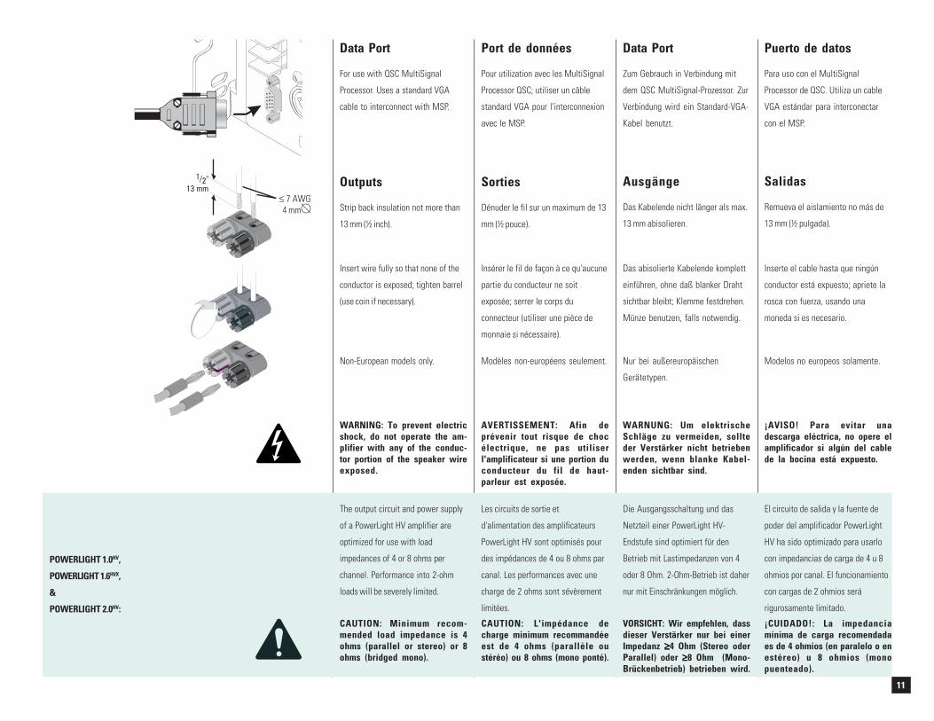
Outputs
Strip back insulation not more than
13 mm (½ inch).
Sorties
Dénuder le fil sur un maximum de 13
mm (½ pouce).
Ausgänge
Das Kabelende nicht länger als max.
13 mm abisolieren.
Salidas
Remueva el aislamiento no más de
13 mm (½ pulgada).
Non-European models only.
Insérer le fil de façon à ce qu'aucune
partie du conducteur ne soit
exposée; serrer le corps du
connecteur (utiliser une pièce de
monnaie si nécessaire).
Das abisolierte Kabelende komplett
einführen, ohne daß blanker Draht
sichtbar bleibt; Klemme festdrehen.
Münze benutzen, falls notwendig.
Inserte el cable hasta que ningún
conductor está expuesto; apriete la
rosca con fuerza, usando una
moneda si es necesario.
The output circuit and power supply
of a PowerLight HV amplifier are
optimized for use with load
impedances of 4 or 8 ohms per
channel. Performance into 2-ohm
loads will be severely limited.
Les circuits de sortie et
d'alimentation des amplificateurs
PowerLight HV sont optimisés pour
des impédances de 4 ou 8 ohms par
canal. Les performances avec une
charge de 2 ohms sont sévèrement
limitées.
El circuito de salida y la fuente de
poder del amplificador PowerLight
HV ha sido optimizado para usarlo
con impedancias de carga de 4 u 8
ohmios por canal. El funcionamiento
con cargas de 2 ohmios será
rigurosamente limitado.
Insert wire fully so that none of the
conductor is exposed; tighten barrel
(use coin if necessary).
Modèles non-européens seulement. Nur bei außereuropäischen
Gerätetypen.
Modelos no europeos solamente.
Die Ausgangsschaltung und das
Netzteil einer PowerLight HV-
Endstufe sind optimiert für den
Betrieb mit Lastimpedanzen von 4
oder 8 Ohm. 2-Ohm-Betrieb ist daher
nur mit Einschränkungen möglich.
CAUTION: Minimum recom-mended load impedance is 4ohms (parallel or stereo) or 8ohms (bridged mono).
CAUTION: L'impédance decharge minimum recommandéeest de 4 ohms (parallèle oustéréo) ou 8 ohms (mono ponté).
VORSICHT: Wir empfehlen, dassdieser Verstärker nur bei einerImpedanz ≥≥≥≥≥4 Ohm (Stereo oderParallel) oder ≥≥≥≥≥8 Ohm (Mono-Brückenbetrieb) betrieben wird.
¡CUIDADO!: La impedanciamínima de carga recomendadaes de 4 ohmios (en paralelo o enestéreo) u 8 ohmios (monopuenteado).
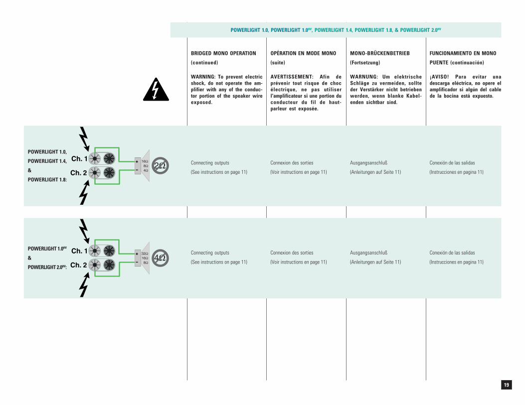
WARNING: To prevent electricshock, do not operate the am-plifier with any of the conduc-tor portion of the speaker wireexposed.
¡AVISO! Para evitar unadescarga eléctrica, no opere elamplificador si algún del cablede la bocina está expuesto.
AVERTISSEMENT: Afin deprévenir tout risque de chocélectrique, ne pas utiliserl'amplificateur si une portion duconducteur du fil de haut-parleur est exposée.
WARNUNG: Um elektrischeSchläge zu vermeiden, sollteder Verstärker nicht betriebenwerden, wenn blanke Kabel-enden sichtbar sind.
POWERLIGHT 1.0HV,
POWERLIGHT 1.6HVX,
&
POWERLIGHT 2.0HV:
Data Port
For use with QSC MultiSignal
Processor. Uses a standard VGA
cable to interconnect with MSP.
Port de données
Pour utilization avec les MultiSignal
Processor QSC; utiliser un câble
standard VGA pour l'interconnexion
avec le MSP.
Data Port
Zum Gebrauch in Verbindung mit
dem QSC MultiSignal-Prozessor. Zur
Verbindung wird ein Standard-VGA-
Kabel benutzt.
Puerto de datos
Para uso con el MultiSignal
Processor de QSC. Utiliza un cable
VGA estándar para interconectar
con el MSP.
≤ 7 AWG4 mm
12
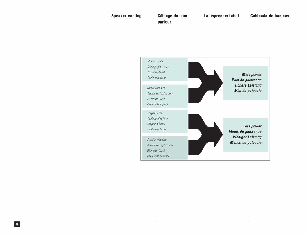
Speaker cabling Câblage du haut-parleur
Lautsprecherkabel Cableado de bocinas
Shorter cable
Câblage plus court
Kürzeres Kabel
Cable más corto
Larger wire size
Section du fil plus gros
Stärkerer Draht
Cable más espeso
More powerPlus de puissance
Höhere LeistungMás de potencia
Longer cable
Câblage plus long
Längeres Kabel
Cable más largo
Smaller wire size
Section du fil plus petit
Dünnerer Draht
Cable más estrecho
Less powerMoins de puissance
Weniger LeistungMenos de potencia
13
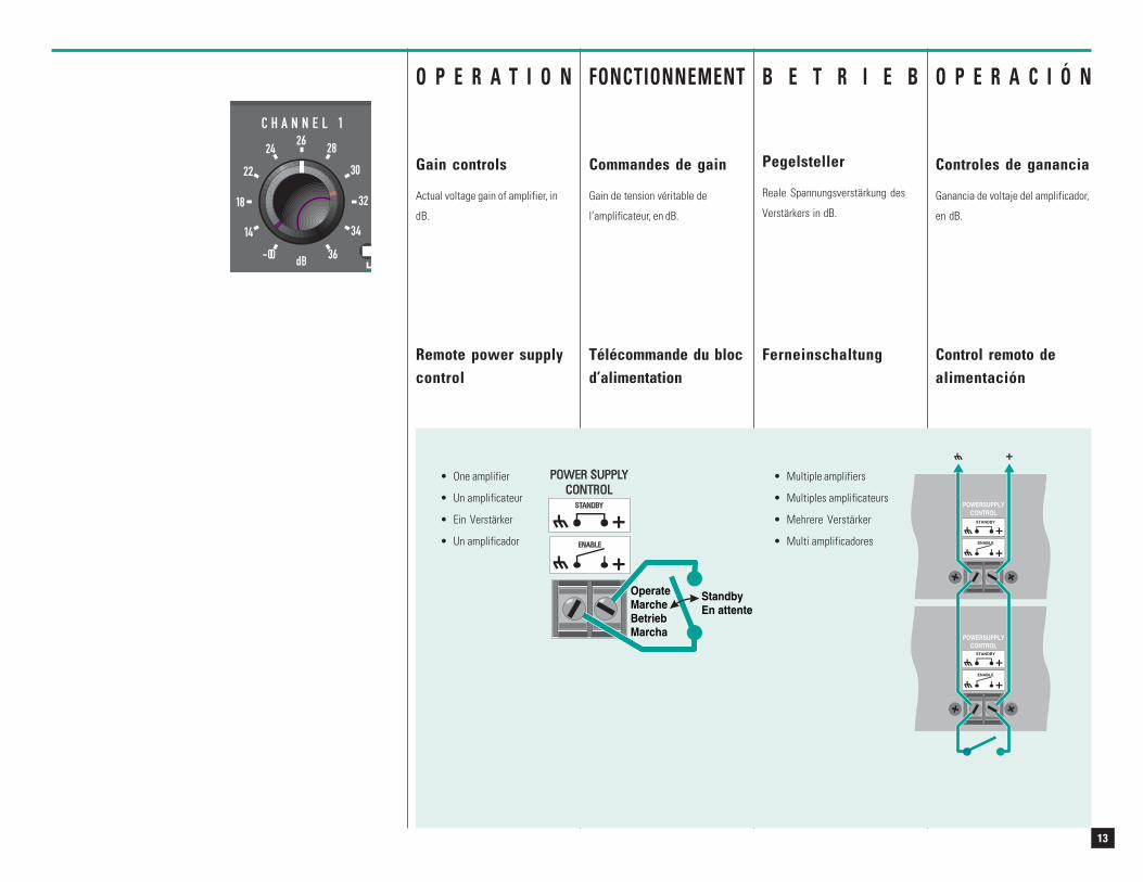
• One amplifier
• Un amplificateur
• Ein Verstärker
• Un amplificador
• Multiple amplifiers
• Multiples amplificateurs
• Mehrere Verstärker
• Multi amplificadores
OperateMarcheBetriebMarcha
StandbyEn attente
O P E R A T I O N
Gain controls
Actual voltage gain of amplifier, in
dB.
FONCTIONNEMENT
Commandes de gain
Gain de tension véritable de
l’amplificateur, en dB.
Ferneinschaltung
O P E R A C I Ó N
Controles de ganancia
Ganancia de voltaje del amplificador,
en dB.
Remote power supplycontrol
Télécommande du blocd’alimentation
Control remoto dealimentación
B E T R I E B
Pegelsteller
Reale Spannungsverstärkung des
Verstärkers in dB.
14
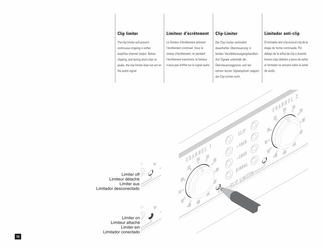
Clip limiter
The clip limiter will prevent
continuous clipping in either
amplifier channel output. Below
clipping, and during short clips on
peaks, the clip limiter does not act on
the audio signal.
Limiteur d'écrêtement
Le limiteur d'écrêtement prévient
l'écrêtement continuel. Sous le
niveau d'écrêtement, et pendant
l'écrêtement transitoire, le limiteur
n'aura pas d'effet sur le signal audio.
Clip-Limiter
Der Clip-Limiter verhindert
dauerhafter Übersteuerung in
beiden Verstärkerausgangskanälen.
Auf Signale unterhalb der
Übersteuerunggrenze und bei
extrem kurzen Signalspitzen reagiert
der Clip-Limiter nicht.
Limitador anti-clip
El limitador anti-clip evita el clip de la
etapa de forma continuada. Por
debajo de la sefial de clip y durante
breves clips debidos a picos de señal,
el limitador no actuará sobre la señal
de audio.
C L I P
- 10 d B
- 2 0 d B
S I G N A L
C L I P L I M I T E R
24
34
2628
30
32
22
20
16
10 dB
C H A N N E L 2
24
34
2628
30
32
22
20
16
10 dB
C H A N N E L 1
-∞-∞10
Limiter offLimiteur détaché
Limiter ausLimitador desconectado
-∞-∞10
Limiter onLimiteur attaché
Limiter einLimitador conectado
15
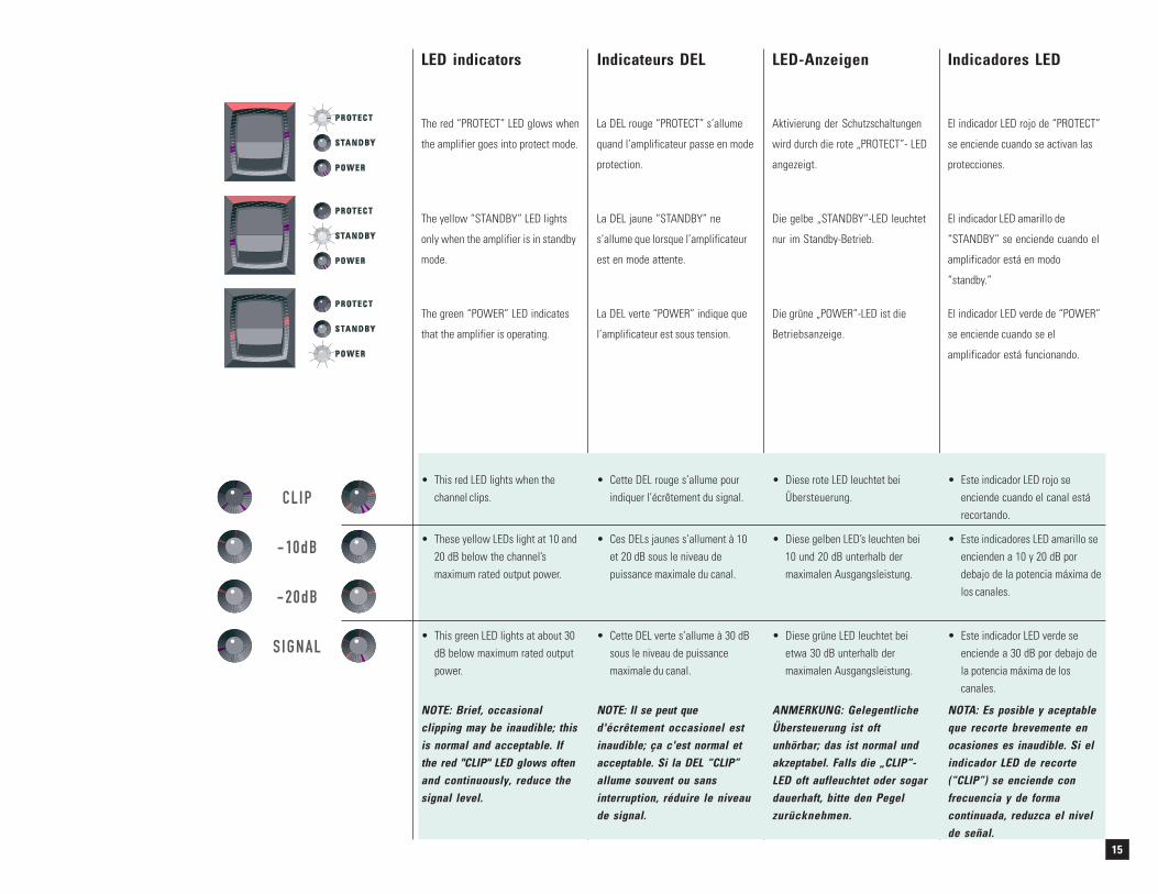
LED indicators Indicateurs DEL LED-Anzeigen Indicadores LED
• This red LED lights when thechannel clips.
• Este indicador LED rojo seenciende cuando el canal estárecortando.
• Cette DEL rouge s’allume pourindiquer l’écrêtement du signal.
• Diese rote LED leuchtet beiÜbersteuerung.
• Diese grüne LED leuchtet beietwa 30 dB unterhalb dermaximalen Ausgangsleistung.
The red “PROTECT” LED glows when
the amplifier goes into protect mode.
The yellow “STANDBY” LED lights
only when the amplifier is in standby
mode.
The green “POWER” LED indicates
that the amplifier is operating.
La DEL rouge “PROTECT” s’allume
quand l’amplificateur passe en mode
protection.
La DEL jaune “STANDBY” ne
s’allume que lorsque l’amplificateur
est en mode attente.
La DEL verte “POWER” indique que
l’amplificateur est sous tension.
Aktivierung der Schutzschaltungen
wird durch die rote „PROTECT”- LED
angezeigt.
Die gelbe „STANDBY”-LED leuchtet
nur im Standby-Betrieb.
Die grüne „POWER”-LED ist die
Betriebsanzeige.
El indicador LED rojo de “PROTECT”
se enciende cuando se activan las
protecciones.
El indicador LED amarillo de
“STANDBY” se enciende cuando el
amplificador está en modo
“standby.”
El indicador LED verde de “POWER”
se enciende cuando se el
amplificador está funcionando.
• These yellow LEDs light at 10 and20 dB below the channel’smaximum rated output power.
• This green LED lights at about 30dB below maximum rated outputpower.
NOTE: Brief, occasionalclipping may be inaudible; thisis normal and acceptable. Ifthe red "CLIP" LED glows oftenand continuously, reduce thesignal level.
• Ces DELs jaunes s’allument à 10et 20 dB sous le niveau depuissance maximale du canal.
• Cette DEL verte s’allume à 30 dBsous le niveau de puissancemaximale du canal.
NOTE: Il se peut qued'écrêtement occasionel estinaudible; ça c'est normal etacceptable. Si la DEL “CLIP”allume souvent ou sansinterruption, réduire le niveaude signal.
• Diese gelben LED’s leuchten bei10 und 20 dB unterhalb dermaximalen Ausgangsleistung.
ANMERKUNG: GelegentlicheÜbersteuerung ist oftunhörbar; das ist normal undakzeptabel. Falls die „CLIP“-LED oft aufleuchtet oder sogardauerhaft, bitte den Pegelzurücknehmen.
• Este indicadores LED amarillo seencienden a 10 y 20 dB pordebajo de la potencia máxima delos canales.
• Este indicador LED verde seenciende a 30 dB por debajo dela potencia máxima de loscanales.
NOTA: Es posible y aceptableque recorte brevemente enocasiones es inaudible. Si elindicador LED de recorte(“CLIP”) se enciende confrecuencia y de formacontinuada, reduzca el nivelde señal.
16
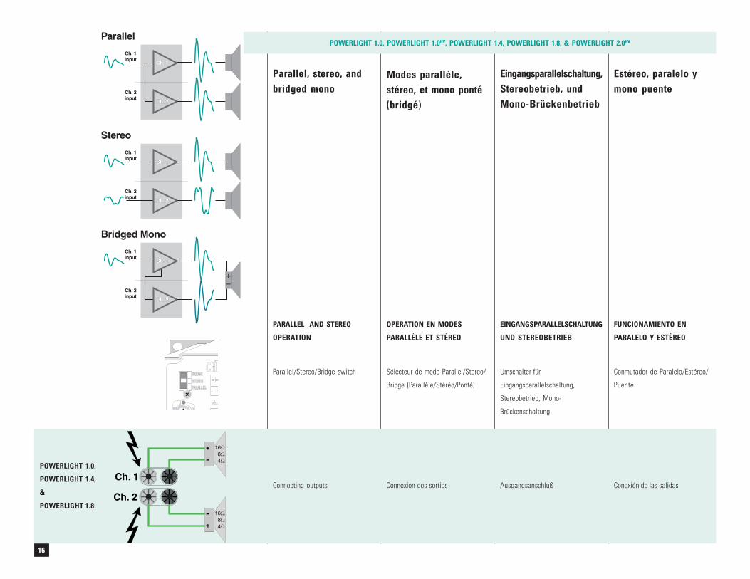
Parallel, stereo, andbridged mono
Modes parallèle,stéreo, et mono ponté(bridgé)
Eingangsparallelschaltung,Stereobetrieb, undMono-Brückenbetrieb
Estéreo, paralelo ymono puente
Ch. 1Ch. 1
Ch. 1Ch. 1
Ch. 1Ch. 1
Ch. 2Ch. 2
Ch. 2Ch. 2
Ch. 2Ch. 2
Ch. 1input
Ch. 1input
Ch. 1input
Ch. 2input
Ch. 2input
Ch. 2input
Parallel
Stereo
Bridged Mono
STEREOPARALLEL
BRIDGECH 1
DATA
PORT
1684
ΩΩΩ
1684
ΩΩΩ
PARALLEL AND STEREO
OPERATION
OPÉRATION EN MODES
PARALLÈLE ET STÉREO
EINGANGSPARALLELSCHALTUNG
UND STEREOBETRIEB
FUNCIONAMIENTO EN
PARALELO Y ESTÉREO
Parallel/Stereo/Bridge switch Sélecteur de mode Parallel/Stereo/
Bridge (Parallèle/Stéréo/Ponté)
Umschalter für
Eingangsparallelschaltung,
Stereobetrieb, Mono-
Brückenschaltung
Conmutador de Paralelo/Estéreo/
Puente
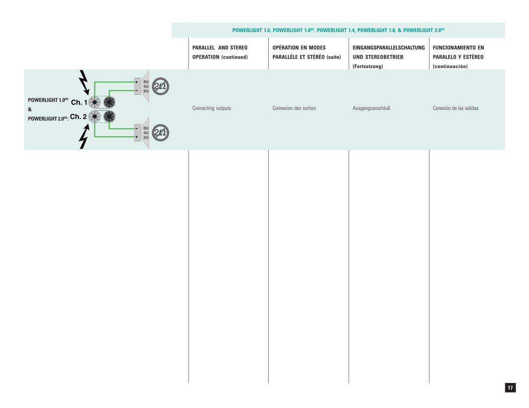
Connecting outputs Connexion des sorties Ausgangsanschluß Conexión de las salidas
POWERLIGHT 1.0,
POWERLIGHT 1.4,
&
POWERLIGHT 1.8:
POWERLIGHT 1.0, POWERLIGHT 1.0HV, POWERLIGHT 1.4, POWERLIGHT 1.8, & POWERLIGHT 2.0HV
17
2Ω2Ω
2Ω2Ω
Connecting outputs Connexion des sorties Ausgangsanschluß Conexión de las salidasPOWERLIGHT 1.0HV
&
POWERLIGHT 2.0HV:
POWERLIGHT 1.0, POWERLIGHT 1.0HV, POWERLIGHT 1.4, POWERLIGHT 1.8, & POWERLIGHT 2.0HV
PARALLEL AND STEREO
OPERATION (continued)
OPÉRATION EN MODES
PARALLÈLE ET STÉRÉO (suite)
EINGANGSPARALLELSCHALTUNG
UND STEREOBETRIEB
(Fortsetzung)
FUNCIONAMIENTO EN
PARALELO Y ESTÉREO
(continuación)
18
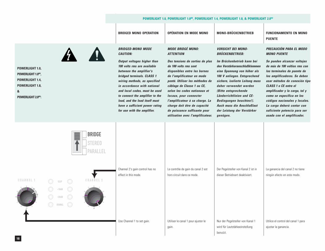
BRIDGED MONO OPERATION MONO-BRÜCKENBETRIEB FUNCIONAMIENTO EN MONO
PUENTE
OPÉRATION EN MODE MONO
STEREOPARALLEL
BRIDGE
dB dB
CLIP
-10dB
-20dB
SIGNAL
C H A N N E L 1 C H A N N E L 2
Channel 2's gain control has no
effect in this mode.
Le contrôle de gain du canal 2 est
hors circuit dans ce mode.
Utiliser le canal 1 pour ajuster le
gain.
Use Channel 1 to set gain.
Der Pegelsteller von Kanal 2 ist in
dieser Betriebsart deaktiviert.
Nur der Pegelsteller von Kanal 1
wird für Lautstärkeeinstellung
benutzt.
La ganancia del canal 2 no tiene
ningún efecto en este modo.
Utilice el control del canal 1 para
ajustar la ganancia.
POWERLIGHT 1.0, POWERLIGHT 1.0HV, POWERLIGHT 1.4, POWERLIGHT 1.8, & POWERLIGHT 2.0HV
POWERLIGHT 1.0,
POWERLIGHT 1.0HV,
POWERLIGHT 1.4,
POWERLIGHT 1.8,
&
POWERLIGHT 2.0HV:
BRIDGED-MONO MODECAUTION:
Output voltages higher than100 volts rms are availablebetween the amplifier'sbridged terminals. CLASS 1wiring methods, as specifiedin accordance with nationaland local codes, must be usedto connect the amplifier to theload, and the load itself musthave a sufficient power ratingfor use with the amplifier.
PRECAUCIÓN PARA EL MODOMONO PUENTE
Se pueden alcanzar voltajesde más de 100 voltios rms conlas terminales de puente delos amplificadores. Se debenusar métodos de conexión tipoCLASS 1 o CE entre elamplificador y la carga, tal ycomo se especifica en loscódigos nacionales y locales.La carga deberá contar consuficiente potencia para serusada con el amplificador.
VORSICHT BEI MONO-BRÜCKENBETRIEB:
Im Brückenbetrieb kann beiden Verstärkeranschlußklemmeneine Spannung von höher als100 V anliegen. Entsprechendsichere, isolierte Leitung mussdaher verwendet werden(Bitte entsprechendeLänderrichtlinien und CE-Bedingungen beachten!).Auch muss die Anschlußlastder Leistung der Verstärkergenügen.
MODE BRIDGÉ MONO:ATTENTION
Des tensions de sorties de plusde 100 volts rms sontdisponibles entre les bornesde l'amplificateur en modeponté. Utiliser les méthodes decâblage de Classe 1 ou CE,selon les codes nationaux etlocaux, pour connecterl'amplificateur à sa charge. Lacharge doit être de capacitéde puissance suffisante pourutilisation avec l'amplificateur.
19
3216
8
ΩΩΩ
4Ω4Ω
Connecting outputs
(See instructions on page 11)
Connexion des sorties
(Voir instructions en page 11)
Ausgangsanschluß
(Anleitungen auf Seite 11)
Conexión de las salidas
(Instrucciones en pagina 11)
1684
ΩΩΩ
2Ω2Ω
Connecting outputs
(See instructions on page 11)
Connexion des sorties
(Voir instructions en page 11)
Ausgangsanschluß
(Anleitungen auf Seite 11)
Conexión de las salidas
(Instrucciones en pagina 11)
POWERLIGHT 1.0,
POWERLIGHT 1.4,
&
POWERLIGHT 1.8:
POWERLIGHT 1.0HV
&
POWERLIGHT 2.0HV:
POWERLIGHT 1.0, POWERLIGHT 1.0HV, POWERLIGHT 1.4, POWERLIGHT 1.8, & POWERLIGHT 2.0HV
WARNING: To prevent electricshock, do not operate the am-plifier with any of the conduc-tor portion of the speaker wireexposed.
¡AVISO! Para evitar unadescarga eléctrica, no opere elamplificador si algún del cablede la bocina está expuesto.
AVERTISSEMENT: Afin deprévenir tout risque de chocélectrique, ne pas utiliserl'amplificateur si une portion duconducteur du fil de haut-parleur est exposée.
WARNUNG: Um elektrischeSchläge zu vermeiden, sollteder Verstärker nicht betriebenwerden, wenn blanke Kabel-enden sichtbar sind.
BRIDGED MONO OPERATION
(continued)
MONO-BRÜCKENBETRIEB
(Fortsetzung)
FUNCIONAMIENTO EN MONO
PUENTE (continuación)
OPÉRATION EN MODE MONO
(suite)
20
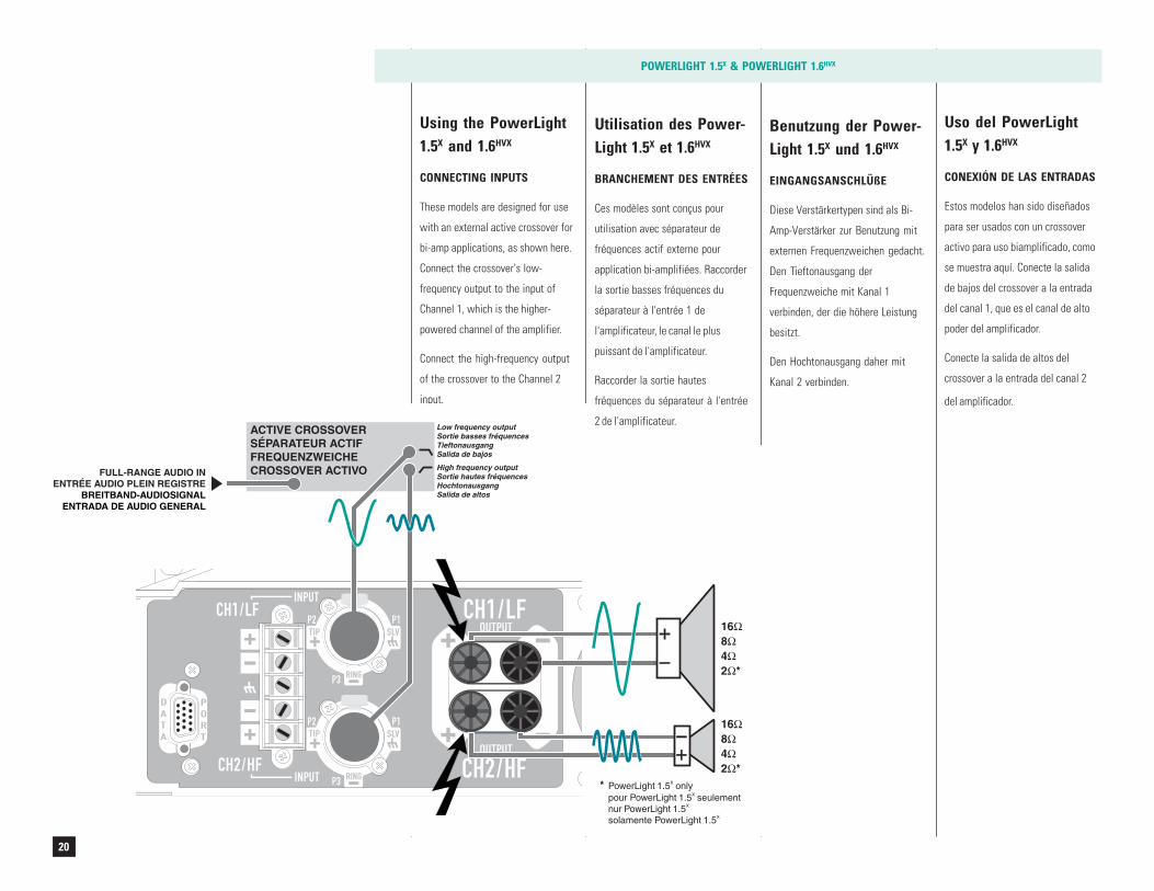
Using the PowerLight1.5X and 1.6HVX
CONNECTING INPUTS
These models are designed for use
with an external active crossover for
bi-amp applications, as shown here.
Connect the crossover's low-
frequency output to the input of
Channel 1, which is the higher-
powered channel of the amplifier.
Connect the high-frequency output
of the crossover to the Channel 2
input.
POWERLIGHT 1.5X & POWERLIGHT 1.6HVX
Uso del PowerLight1.5X y 1.6HVX
CONEXIÓN DE LAS ENTRADAS
Estos modelos han sido diseñados
para ser usados con un crossover
activo para uso biamplificado, como
se muestra aquí. Conecte la salida
de bajos del crossover a la entrada
del canal 1, que es el canal de alto
poder del amplificador.
Conecte la salida de altos del
crossover a la entrada del canal 2
del amplificador.
Benutzung der Power-Light 1.5X und 1.6HVX
EINGANGSANSCHLÜßE
Diese Verstärkertypen sind als Bi-
Amp-Verstärker zur Benutzung mit
externen Frequenzweichen gedacht.
Den Tieftonausgang der
Frequenzweiche mit Kanal 1
verbinden, der die höhere Leistung
besitzt.
Den Hochtonausgang daher mit
Kanal 2 verbinden.
SLV
RING
TIPP2 P1
P3
RING
P2 P1
P3
DATA
PORT SLV
RING
TIP
OUTPUT
OUTPUT
INPUT
INPUTCH1/LF
CH2/HFCH2/HF
CH1/LF
ACTIVE CROSSOVERSÉPARATEUR ACTIFFREQUENZWEICHECROSSOVER ACTIVO High frequency output
Sortie hautes fréquencesHochtonausgangSalida de altos
FULL-RANGE AUDIO INENTRÉE AUDIO PLEIN REGISTRE
BREITBAND-AUDIOSIGNALENTRADA DE AUDIO GENERAL
16842 *
ΩΩΩΩ
16842 *
ΩΩΩΩ
Low frequency outputSortie basses fréquencesTieftonausgangSalida de bajos
* PowerLight 1.5 onlypour PowerLight 1.5 seulementnur PowerLight 1.5
PowerLight 1.5
X
X
X
Xsolamente
Utilisation des Power-Light 1.5X et 1.6HVX
BRANCHEMENT DES ENTRÉES
Ces modèles sont conçus pour
utilisation avec séparateur de
fréquences actif externe pour
application bi-amplifiées. Raccorder
la sortie basses fréquences du
séparateur à l'entrée 1 de
l'amplificateur, le canal le plus
puissant de l'amplificateur.
Raccorder la sortie hautes
fréquences du séparateur à l'entrée
2 de l'amplificateur.
21
Instead of the "combo" connectors,
you can also use the screw terminals
for connecting inputs.
POWERLIGHT 1.5X & POWERLIGHT 1.6HVX
Au lieu des connecteurs "Combo,"
vous pouvez utiliser les bornes pour
le branchement des entrées.
En lugar de conectores ‘combo’,
también puede usar las terminales
de rosca para conectar entradas.
Anstelle der „Combo“-Steckver-
binder können Sie auch die
Schraubklemmen als Eingänge
verwenden.
CONNECTING OUTPUTS
Connect the low-frequency
loudspeaker to Channel 1's output,
and the high-frequency loudspeaker
to Channel 2's output, as shown
(page 20); see page 11 for important
instructions on safely connecting
loudspeaker loads.
PL 1.6HVX only: Do not use speaker
loads of less than 4 ohms per
channel.
BRANCHEMENT DES SORTIES
Brancher le haut-parleur de basses
fréquences à la sortie canal 1 de
l'amplificateur, et le haut-parleur de
hautes fréquences à la sortie canal
2, tel que montré (page 20). Voir à la
page 11 pour la notice de securité
pour le branchement des haut-
parleurs.
PL 1.6HVX seulement: Ne pas
utiliser de haut-parleurs donnant
une charge totale de moins de 4
ohms par canal.
AUSGANGSVERBINDUNGEN
Verbinden Sie den
Tieftonlautsprecher mit dem
Ausgang von Kanal 1, und den
Hochtonlautsprecher mit dem
Ausgang von Kanal 2, wie gezeigt
(Seite 20). Beachten Sie die Seite 11
für sichere Verbindung.
Nur PL1.6HVX: Benutzen Sie keine
Lautsprecherlasten von unter 4 Ohm
pro Kanal.
CONEXIÓN DE SALIDAS
Conecte las bocinas de bajos a la
salida del canal 1, y las bocinas de
altos con la salida del canal 2 como
se muestra (página 20). Léase la
página 11 para instrucciones de
seguridad cuando se ejecuten este
tipo de conexiones con bocinas.
Sólo PowerLight 1.6HVX: No use
bocinas de menos de 4 ohmios por
canal.
22
SLV
RING
TIPP2 P1
P3
PARALLELOUTPUT
LINE LEVEL OUTPUT
INPUT RING
P2 P1
P3
DATA
PORT
OUTPUT
SLV
RING
TIP
16842 *
ΩΩΩΩ
PARALLELOUTPUT
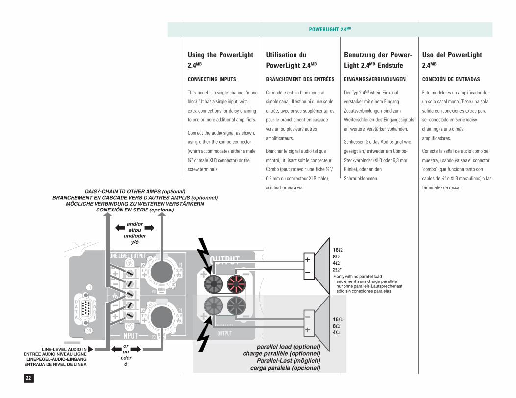
parallel load (optional)charge parallèle (optionnel)
Parallel-Last (möglich)carga paralela (opcional)
LINE-LEVEL AUDIO INENTRÉE AUDIO NIVEAU LIGNE
LINEPEGEL-AUDIO-EINGANGENTRADA DE NIVEL DE LÍNEA
orou
oderó
DAISY-CHAIN TO OTHER AMPS (optional)BRANCHEMENT EN CASCADE VERS D’AUTRES AMPLIS (optionnel)
MÖGLICHE VERBINDUNG ZU WEITEREN VERSTÄRKERNCONEXIÓN EN SERIE (opcional)
and/oret/ou
und/odery/ó
1684
ΩΩΩ
* only with no parallel loadsans charge parallèle
nur ohne parallele Lautsprecherlastsólo sin conexiones paralelas
seulement
Using the PowerLight2.4MB
CONNECTING INPUTS
This model is a single-channel "mono
block." It has a single input, with
extra connections for daisy-chaining
to one or more additional amplifiers.
Connect the audio signal as shown,
using either the combo connector
(which accommodates either a male
¼" or male XLR connector) or the
screw terminals.
POWERLIGHT 2.4MB
Utilisation duPowerLight 2.4MB
BRANCHEMENT DES ENTRÉES
Ce modèle est un bloc monoral
simple canal. Il est muni d'une seule
entrée, avec prises supplémentaires
pour le branchement en cascade
vers un ou plusieurs autres
amplificateurs.
Brancher le signal audio tel que
montré, utilisant soit le connecteur
Combo (peut recevoir une fiche ¼"/
6.3 mm ou connecteur XLR mâle),
soit les bornes à vis.
Uso del PowerLight2.4MB
CONEXIÓN DE ENTRADAS
Este modelo es un amplificador de
un solo canal mono. Tiene una sola
salida con conexiones extras para
ser conectado en serie (daisy-
chaining) a uno o más
amplificadores.
Conecte la señal de audio como se
muestra, usando ya sea el conector
‘combo’ (que funciona tanto con
cables de ¼" o XLR masculinos) o las
terminales de rosca.
Benutzung der Power-Light 2.4MB Endstufe
EINGANGSVERBINDUNGEN
Der Typ 2.4MB ist ein Einkanal-
verstärker mit einem Eingang.
Zusatzverbindungen sind zum
Weiterschleifen des Eingangssignals
an weitere Verstärker vorhanden.
Schliessen Sie das Audiosignal wie
gezeigt an, entweder am Combo-
Steckverbinder (XLR oder 6,3 mm
Klinke), oder an den
Schraubklemmen.
23
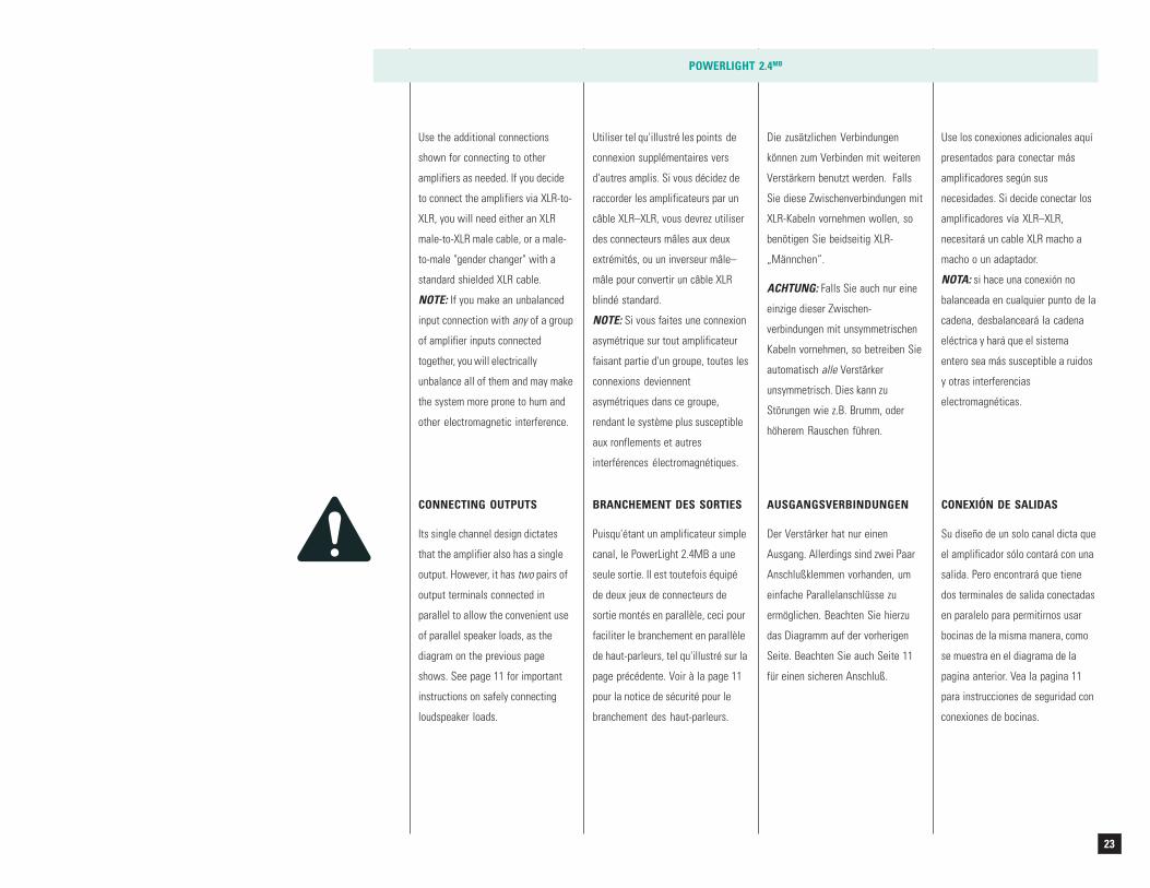
Use the additional connections
shown for connecting to other
amplifiers as needed. If you decide
to connect the amplifiers via XLR-to-
XLR, you will need either an XLR
male-to-XLR male cable, or a male-
to-male "gender changer" with a
standard shielded XLR cable.
NOTE: If you make an unbalanced
input connection with any of a group
of amplifier inputs connected
together, you will electrically
unbalance all of them and may make
the system more prone to hum and
other electromagnetic interference.
POWERLIGHT 2.4MB
Utiliser tel qu'illustré les points de
connexion supplémentaires vers
d'autres amplis. Si vous décidez de
raccorder les amplificateurs par un
câble XLR–XLR, vous devrez utiliser
des connecteurs mâles aux deux
extrémités, ou un inverseur mâle–
mâle pour convertir un câble XLR
blindé standard.
NOTE: Si vous faites une connexion
asymétrique sur tout amplificateur
faisant partie d'un groupe, toutes les
connexions deviennent
asymétriques dans ce groupe,
rendant le système plus susceptible
aux ronflements et autres
interférences électromagnétiques.
Use los conexiones adicionales aquí
presentados para conectar más
amplificadores según sus
necesidades. Si decide conectar los
amplificadores vía XLR–XLR,
necesitará un cable XLR macho a
macho o un adaptador.
NOTA: si hace una conexión no
balanceada en cualquier punto de la
cadena, desbalanceará la cadena
eléctrica y hará que el sistema
entero sea más susceptible a ruidos
y otras interferencias
electromagnéticas.
CONNECTING OUTPUTS
Its single channel design dictates
that the amplifier also has a single
output. However, it has two pairs of
output terminals connected in
parallel to allow the convenient use
of parallel speaker loads, as the
diagram on the previous page
shows. See page 11 for important
instructions on safely connecting
loudspeaker loads.
BRANCHEMENT DES SORTIES
Puisqu'étant un amplificateur simple
canal, le PowerLight 2.4MB a une
seule sortie. Il est toutefois équipé
de deux jeux de connecteurs de
sortie montés en parallèle, ceci pour
faciliter le branchement en parallèle
de haut-parleurs, tel qu'illustré sur la
page précédente. Voir à la page 11
pour la notice de sécurité pour le
branchement des haut-parleurs.
CONEXIÓN DE SALIDAS
Su diseño de un solo canal dicta que
el amplificador sólo contará con una
salida. Pero encontrará que tiene
dos terminales de salida conectadas
en paralelo para permitirnos usar
bocinas de la misma manera, como
se muestra en el diagrama de la
pagina anterior. Vea la pagina 11
para instrucciones de seguridad con
conexiones de bocinas.
Die zusätzlichen Verbindungen
können zum Verbinden mit weiteren
Verstärkern benutzt werden. Falls
Sie diese Zwischenverbindungen mit
XLR-Kabeln vornehmen wollen, so
benötigen Sie beidseitig XLR-
„Männchen“.
ACHTUNG: Falls Sie auch nur eine
einzige dieser Zwischen-
verbindungen mit unsymmetrischen
Kabeln vornehmen, so betreiben Sie
automatisch alle Verstärker
unsymmetrisch. Dies kann zu
Störungen wie z.B. Brumm, oder
höherem Rauschen führen.
AUSGANGSVERBINDUNGEN
Der Verstärker hat nur einen
Ausgang. Allerdings sind zwei Paar
Anschlußklemmen vorhanden, um
einfache Parallelanschlüsse zu
ermöglichen. Beachten Sie hierzu
das Diagramm auf der vorherigen
Seite. Beachten Sie auch Seite 11
für einen sicheren Anschluß.
24
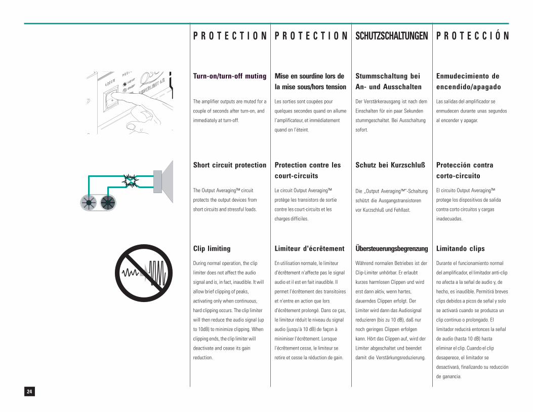
Turn-on/turn-off muting
The amplifier outputs are muted for a
couple of seconds after turn-on, and
immediately at turn-off.
P R O T E C T I O N
Short circuit protection
The Output Averaging™ circuit
protects the output devices from
short circuits and stressful loads.
SCHUTZSCHALTUNGEN P R O T E C C I Ó N
Mise en sourdine lors dela mise sous/hors tension
Les sorties sont coupées pour
quelques secondes quand on allume
l’amplificateur, et immédiatement
quand on l’éteint.
Stummschaltung beiAn- und Ausschalten
Der Verstärkerausgang ist nach dem
Einschalten für ein paar Sekunden
stummgeschaltet. Bei Ausschaltung
sofort.
Enmudecimiento deencendido/apagado
Las salidas del amplificador se
enmudecen durante unas segundos
al encender y apagar.
Limiteur d'écrêtement
En utilisation normale, le limiteur
d'écrêtement n'affecte pas le signal
audio et il est en fait inaudible. Il
permet l'écrêtement des transitoires
et n'entre en action que lors
d'écrêtement prolongé. Dans ce ças,
le limiteur réduit le niveau du signal
audio (jusqu'à 10 dB) de façon à
minimiser l'écrêtement. Lorsque
l'écrêtement cesse, le limiteur se
retire et cesse la réduction de gain.
Clip limiting
During normal operation, the clip
limiter does not affect the audio
signal and is, in fact, inaudible. It will
allow brief clipping of peaks,
activating only when continuous,
hard clipping occurs. The clip limiter
will then reduce the audio signal (up
to 10dB) to minimize clipping. When
clipping ends, the clip limiter will
deactivate and cease its gain
reduction.
Übersteuerungsbegrenzung
Während normalen Betriebes ist der
Clip-Limiter unhörbar. Er erlaubt
kurzes harmlosen Clippen und wird
erst dann aktiv, wenn hartes,
dauerndes Clippen erfolgt. Der
Limiter wird dann das Audiosignal
reduzieren (bis zu 10 dB), daß nur
noch geringes Clippen erfolgen
kann. Hört das Clippen auf, wird der
Limiter abgeschaltet und beendet
damit die Verstärkungsreduzierung.
Limitando clips
Durante el funcionamiento normal
del amplificador, el limitador anti-clip
no afecta a la señal de audio y, de
hecho, es inaudible. Permitirá breves
clips debidos a picos de señal y solo
se activará cuando se produzca un
clip continuo o prolongado. El
limitador reducirá entonces la señal
de audio (hasta 10 dB) hasta
eliminar el clip. Cuando el clip
desaperece, el limitador se
desactivará, finalizando su reducción
de ganancia.
P R O T E C T I O N
Protection contre lescourt-circuits
Le circuit Output Averaging™
protège les transistors de sortie
contre les court-circuits et les
charges difficiles.
Schutz bei Kurzschluß
Die „Output Averaging™”-Schaltung
schützt die Ausgangstransistoren
vor Kurzschluß und Fehllast.
Protección contracorto-circuito
El circuito Output Averaging™
protege los dispositivos de salida
contra corto circuitos y cargas
inadecuadas.
25
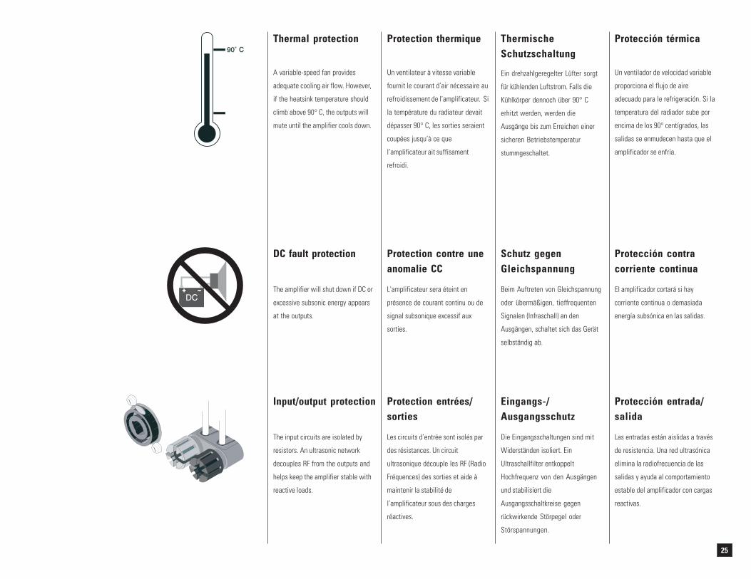
Thermal protection
A variable-speed fan provides
adequate cooling air flow. However,
if the heatsink temperature should
climb above 90° C, the outputs will
mute until the amplifier cools down.
Protection thermique
Un ventilateur à vitesse variable
fournit le courant d’air nécessaire au
refroidissement de l’amplificateur. Si
la température du radiateur devait
dépasser 90° C, les sorties seraient
coupées jusqu’à ce que
l’amplificateur ait suffisament
refroidi.
ThermischeSchutzschaltung
Ein drehzahlgeregelter Lüfter sorgt
für kühlenden Luftstrom. Falls die
Kühlkörper dennoch über 90° C
erhitzt werden, werden die
Ausgänge bis zum Erreichen einer
sicheren Betriebstemperatur
stummgeschaltet.
Protección térmica
Un ventilador de velocidad variable
proporciona el flujo de aire
adecuado para le refrigeración. Si la
temperatura del radiador sube por
encima de los 90° centígrados, las
salidas se enmudecen hasta que el
amplificador se enfría.
Protection contre uneanomalie CC
L'amplificateur sera éteint en
présence de courant continu ou de
signal subsonique excessif aux
sorties.
Schutz gegenGleichspannung
Beim Auftreten von Gleichspannung
oder übermäßigen, tieffrequenten
Signalen (Infraschall) an den
Ausgängen, schaltet sich das Gerät
selbständig ab.
Protección contracorriente continua
El amplificador cortará si hay
corriente continua o demasiada
energía subsónica en las salidas.
Protection entrées/sorties
Les circuits d’entrée sont isolés par
des résistances. Un circuit
ultrasonique découple les RF (Radio
Fréquences) des sorties et aide à
maintenir la stabilité de
l’amplificateur sous des charges
réactives.
DC fault protection
The amplifier will shut down if DC or
excessive subsonic energy appears
at the outputs.
Input/output protection
The input circuits are isolated by
resistors. An ultrasonic network
decouples RF from the outputs and
helps keep the amplifier stable with
reactive loads.
Eingangs-/Ausgangsschutz
Die Eingangsschaltungen sind mit
Widerständen isoliert. Ein
Ultraschallfilter entkoppelt
Hochfrequenz von den Ausgängen
und stabilisiert die
Ausgangsschaltkreise gegen
rückwirkende Störpegel oder
Störspannungen.
Protección entrada/salida
Las entradas están aislidas a través
de resistencia. Una red ultrasónica
elimina la radiofrecuencia de las
salidas y ayuda al comportamiento
estable del amplificador con cargas
reactivas.
26
PowerLight 1.0 PowerLight 1.0HV PowerLight 1.4 PowerLight 1.5X
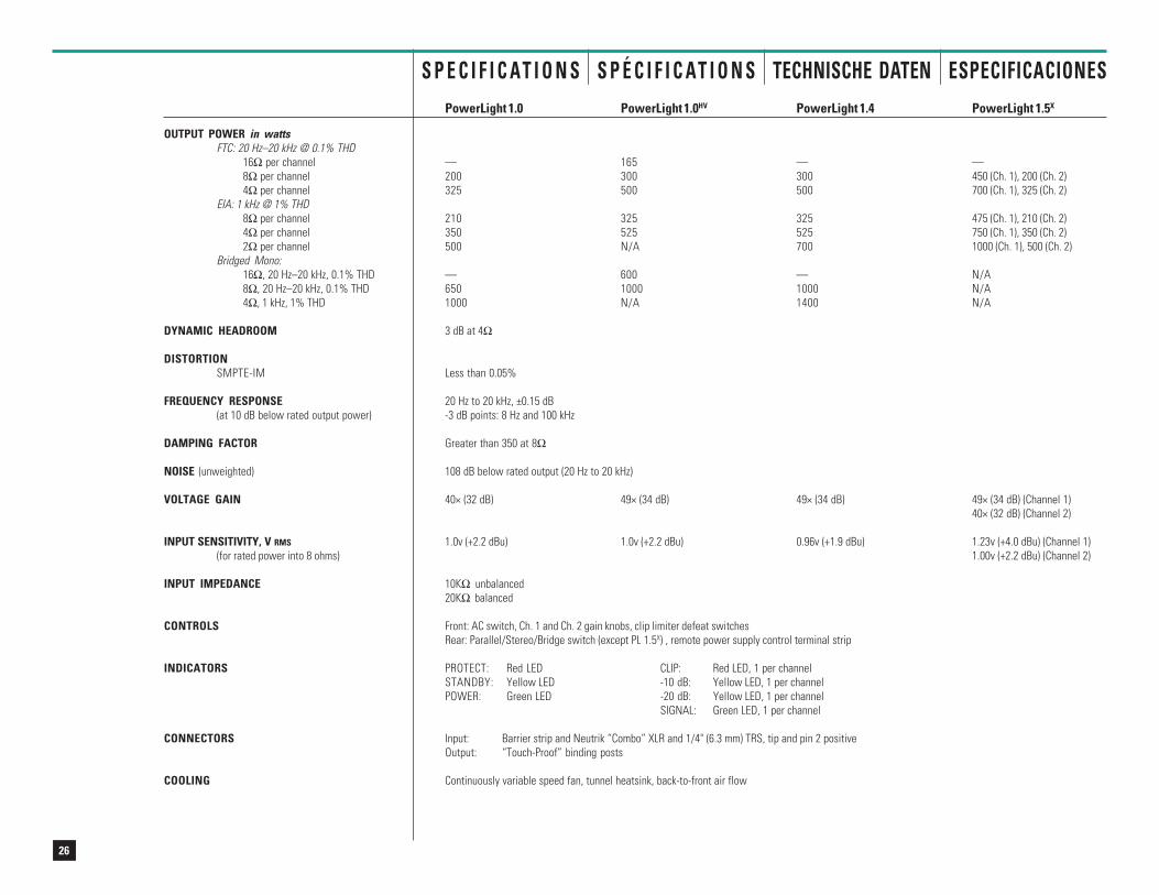
OUTPUT POWER in wattsFTC: 20 Hz–20 kHz @ 0.1% THD
16Ω per channel — 165 — —8Ω per channel 200 300 300 450 (Ch. 1), 200 (Ch. 2)4Ω per channel 325 500 500 700 (Ch. 1), 325 (Ch. 2)
EIA: 1 kHz @ 1% THD8Ω per channel 210 325 325 475 (Ch. 1), 210 (Ch. 2)4Ω per channel 350 525 525 750 (Ch. 1), 350 (Ch. 2)2Ω per channel 500 N/A 700 1000 (Ch. 1), 500 (Ch. 2)
Bridged Mono:16Ω, 20 Hz–20 kHz, 0.1% THD — 600 — N/A8Ω, 20 Hz–20 kHz, 0.1% THD 650 1000 1000 N/A4Ω, 1 kHz, 1% THD 1000 N/A 1400 N/A
DYNAMIC HEADROOM 3 dB at 4Ω
DISTORTIONSMPTE-IM Less than 0.05%
FREQUENCY RESPONSE 20 Hz to 20 kHz, ±0.15 dB(at 10 dB below rated output power) -3 dB points: 8 Hz and 100 kHz
DAMPING FACTOR Greater than 350 at 8Ω
NOISE (unweighted) 108 dB below rated output (20 Hz to 20 kHz)
VOLTAGE GAIN 40× (32 dB) 49× (34 dB) 49× (34 dB) 49× (34 dB) (Channel 1)40× (32 dB) (Channel 2)
INPUT SENSITIVITY, V RMS 1.0v (+2.2 dBu) 1.0v (+2.2 dBu) 0.96v (+1.9 dBu) 1.23v (+4.0 dBu) (Channel 1)(for rated power into 8 ohms) 1.00v (+2.2 dBu) (Channel 2)
INPUT IMPEDANCE 10KΩ unbalanced20KΩ balanced
CONTROLS Front: AC switch, Ch. 1 and Ch. 2 gain knobs, clip limiter defeat switchesRear: Parallel/Stereo/Bridge switch (except PL 1.5X) , remote power supply control terminal strip
INDICATORS PROTECT: Red LED CLIP: Red LED, 1 per channelSTANDBY: Yellow LED -10 dB: Yellow LED, 1 per channelPOWER: Green LED -20 dB: Yellow LED, 1 per channel
SIGNAL: Green LED, 1 per channel
CONNECTORS Input: Barrier strip and Neutrik “Combo” XLR and 1/4" (6.3 mm) TRS, tip and pin 2 positiveOutput: “Touch-Proof” binding posts
COOLING Continuously variable speed fan, tunnel heatsink, back-to-front air flow
S P É C I F I C AT I O N S TECHNISCHE DATEN ESPECIFICACIONESS P E C I F I C AT I O N S
27
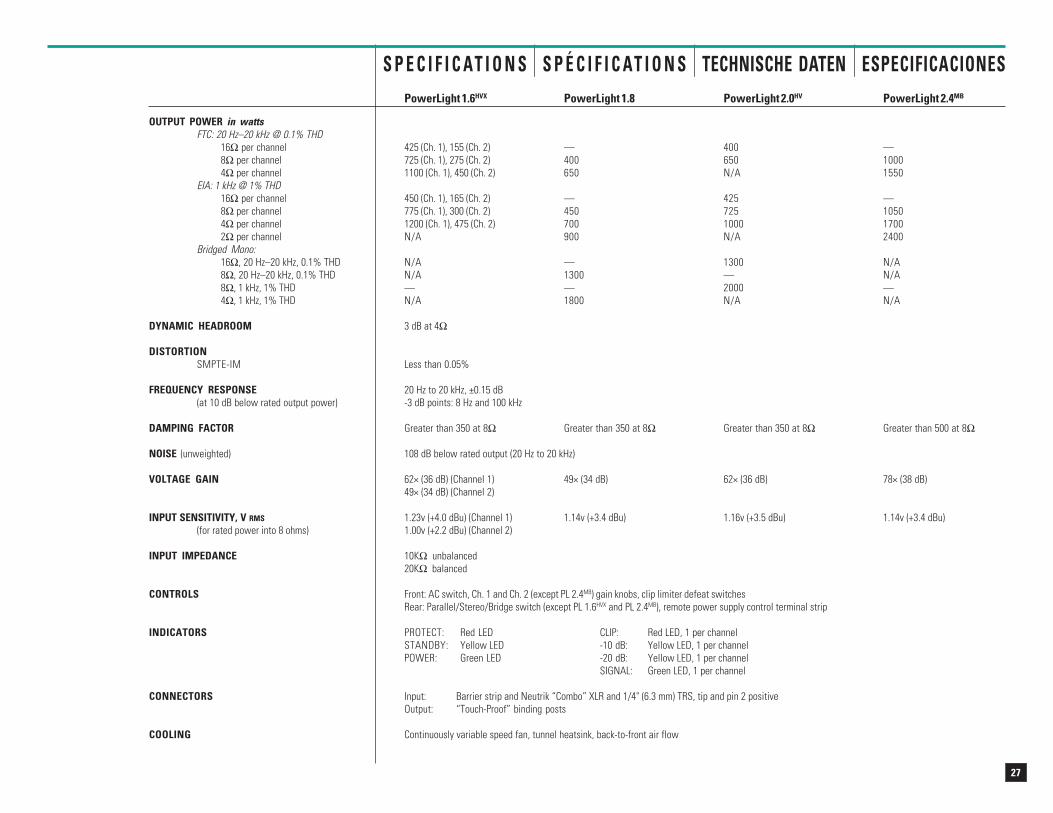
PowerLight 1.6HVX PowerLight 1.8 PowerLight 2.0HV PowerLight 2.4MB
OUTPUT POWER in wattsFTC: 20 Hz–20 kHz @ 0.1% THD
16Ω per channel 425 (Ch. 1), 155 (Ch. 2) — 400 —8Ω per channel 725 (Ch. 1), 275 (Ch. 2) 400 650 10004Ω per channel 1100 (Ch. 1), 450 (Ch. 2) 650 N/A 1550
EIA: 1 kHz @ 1% THD16Ω per channel 450 (Ch. 1), 165 (Ch. 2) — 425 —8Ω per channel 775 (Ch. 1), 300 (Ch. 2) 450 725 10504Ω per channel 1200 (Ch. 1), 475 (Ch. 2) 700 1000 17002Ω per channel N/A 900 N/A 2400
Bridged Mono:16Ω, 20 Hz–20 kHz, 0.1% THD N/A — 1300 N/A8Ω, 20 Hz–20 kHz, 0.1% THD N/A 1300 — N/A8Ω, 1 kHz, 1% THD — — 2000 —4Ω, 1 kHz, 1% THD N/A 1800 N/A N/A
DYNAMIC HEADROOM 3 dB at 4Ω
DISTORTIONSMPTE-IM Less than 0.05%
FREQUENCY RESPONSE 20 Hz to 20 kHz, ±0.15 dB(at 10 dB below rated output power) -3 dB points: 8 Hz and 100 kHz
DAMPING FACTOR Greater than 350 at 8Ω Greater than 350 at 8Ω Greater than 350 at 8Ω Greater than 500 at 8Ω
NOISE (unweighted) 108 dB below rated output (20 Hz to 20 kHz)
VOLTAGE GAIN 62× (36 dB) (Channel 1) 49× (34 dB) 62× (36 dB) 78× (38 dB)49× (34 dB) (Channel 2)
INPUT SENSITIVITY, V RMS 1.23v (+4.0 dBu) (Channel 1) 1.14v (+3.4 dBu) 1.16v (+3.5 dBu) 1.14v (+3.4 dBu)(for rated power into 8 ohms) 1.00v (+2.2 dBu) (Channel 2)
INPUT IMPEDANCE 10KΩ unbalanced20KΩ balanced
CONTROLS Front: AC switch, Ch. 1 and Ch. 2 (except PL 2.4MB) gain knobs, clip limiter defeat switchesRear: Parallel/Stereo/Bridge switch (except PL 1.6HVX and PL 2.4MB), remote power supply control terminal strip
INDICATORS PROTECT: Red LED CLIP: Red LED, 1 per channelSTANDBY: Yellow LED -10 dB: Yellow LED, 1 per channelPOWER: Green LED -20 dB: Yellow LED, 1 per channel
SIGNAL: Green LED, 1 per channel
CONNECTORS Input: Barrier strip and Neutrik “Combo” XLR and 1/4" (6.3 mm) TRS, tip and pin 2 positiveOutput: “Touch-Proof” binding posts
COOLING Continuously variable speed fan, tunnel heatsink, back-to-front air flow
S P E C I F I C AT I O N S S P É C I F I C AT I O N S TECHNISCHE DATEN ESPECIFICACIONES
28
TECHNISCHE DATENS P E C I F I C AT I O N S S P É C I F I C AT I O N S ESPECIFICACIONES
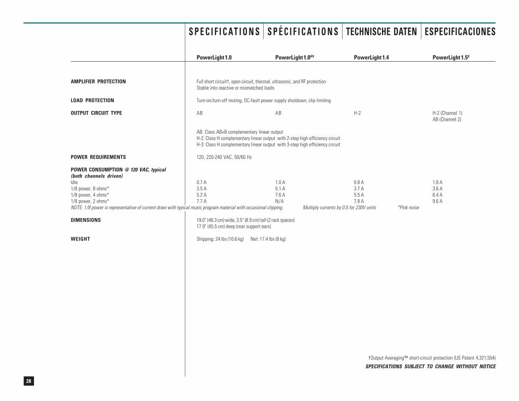
PowerLight 1.0 PowerLight 1.0HV PowerLight 1.4 PowerLight 1.5X
AMPLIFIER PROTECTION Full short circuit†, open circuit, thermal, ultrasonic, and RF protectionStable into reactive or mismatched loads
LOAD PROTECTION Turn-on/turn-off muting, DC-fault power supply shutdown, clip limiting
OUTPUT CIRCUIT TYPE AB AB H-2 H-2 (Channel 1)AB (Channel 2)
AB: Class AB+B complementary linear outputH-2: Class H complementary linear output with 2-step high efficiency circuitH-3: Class H complementary linear output with 3-step high efficiency circuit
POWER REQUIREMENTS 120, 220-240 VAC, 50/60 Hz
POWER CONSUMPTION @ 120 VAC, typical(both channels driven)Idle 0.7 A 1.0 A 0.8 A 1.6 A1/8 power, 8 ohms* 3.5 A 5.1 A 3.7 A 3.6 A1/8 power, 4 ohms* 5.2 A 7.6 A 5.5 A 6.4 A1/8 power, 2 ohms* 7.7 A N/A 7.8 A 9.6 ANOTE: 1/8 power is representative of current draw with typical music program material with occasional clipping. Multiply currents by 0.5 for 230V units *Pink noise
DIMENSIONS 19.0" (48.3 cm) wide, 3.5" (8.9 cm) tall (2 rack spaces)17.9" (45.5 cm) deep (rear support ears)
WEIGHT Shipping: 24 lbs (10.6 kg) Net: 17.4 lbs (8 kg)
†Output Averaging™ short-circuit protection (US Patent 4,321,554)
SPECIFICATIONS SUBJECT TO CHANGE WITHOUT NOTICE
29
TECHNISCHE DATENS P E C I F I C AT I O N S S P É C I F I C AT I O N S ESPECIFICACIONES
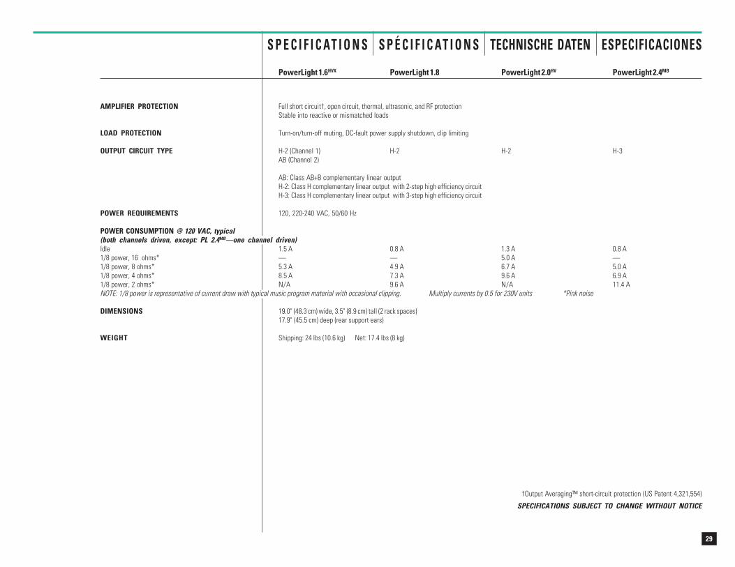
PowerLight 1.6HVX PowerLight 1.8 PowerLight 2.0HV PowerLight 2.4MB
AMPLIFIER PROTECTION Full short circuit†, open circuit, thermal, ultrasonic, and RF protectionStable into reactive or mismatched loads
LOAD PROTECTION Turn-on/turn-off muting, DC-fault power supply shutdown, clip limiting
OUTPUT CIRCUIT TYPE H-2 (Channel 1) H-2 H-2 H-3AB (Channel 2)
AB: Class AB+B complementary linear outputH-2: Class H complementary linear output with 2-step high efficiency circuitH-3: Class H complementary linear output with 3-step high efficiency circuit
POWER REQUIREMENTS 120, 220-240 VAC, 50/60 Hz
POWER CONSUMPTION @ 120 VAC, typical(both channels driven, except: PL 2.4MB—one channel driven)Idle 1.5 A 0.8 A 1.3 A 0.8 A1/8 power, 16 ohms* — — 5.0 A —1/8 power, 8 ohms* 5.3 A 4.9 A 6.7 A 5.0 A1/8 power, 4 ohms* 8.5 A 7.3 A 9.6 A 6.9 A1/8 power, 2 ohms* N/A 9.6 A N/A 11.4 ANOTE: 1/8 power is representative of current draw with typical music program material with occasional clipping. Multiply currents by 0.5 for 230V units *Pink noise
DIMENSIONS 19.0" (48.3 cm) wide, 3.5" (8.9 cm) tall (2 rack spaces)17.9" (45.5 cm) deep (rear support ears)
WEIGHT Shipping: 24 lbs (10.6 kg) Net: 17.4 lbs (8 kg)
†Output Averaging™ short-circuit protection (US Patent 4,321,554)
SPECIFICATIONS SUBJECT TO CHANGE WITHOUT NOTICE
30
W A R R A N T YI N F O R M A T I O N
INFORMATIONS DEG A R A N T I E
G A R A N T I E -B E D I N G U N G E N
INFORMACIÓN DEG A R A N T Í A
Disclaimer
QSC Audio Products, Inc. is not liable
for any damage to speakers,
amplifiers, or any other equipment
that is caused by negligence or
improper installation and/or use of
the PowerLight amplifier.
Product Warranty
QSC guarantees the PowerLight to
be free from defective material and/
or workmanship for a period of three
years from the date of sale, and will
replace defective parts and repair
malfunctioning products under this
warranty when the defect occurs
under normal installation and use—
provided the unit is returned to our
factory via prepaid transportation
with a copy of the proof of purchase,
i.e., sales receipt. This warranty
provides that examination of the
returned product must indicate, in
our judgment, a manufacturing
defect. This warranty does not
extend to any product which has
been subjected to misuse, neglect,
accident, improper installation, or
where the date code has been
removed or defaced.
Décharge
QSC Audio products, Inc. ne peut
être tenu responsable de tout
dommage à des haut-parleurs,
amplificateurs, ou tout autre
équipement qui pourrait être dû à de
la négligence ou mauvaise
installation et/ou utilisation d'un
amplificateur PowerLight.
Garantie de produit
QSC garantit le produit PowerLight
libre de défaut de pièce et/ou de
fabrication, et ce pour une période
de trois ans à partir de la date
d'achat, et remplacera les pièces
défectueuses et réparera le produit
sous l'effet de cette garantie en
autant que le produit est installé et
utilisé de façon normale, et que le
produit est retourné à notre usine
port payé, accompagné d'une copie
de la preuve d'achat, i.e. facture
originale. Cette garantie est
conditionnelle à ce qu'une inspection
du produit retourné révèle, selon
notre jugement, un défaut de
fabrication. Cette garantie ne couvre
pas les produits ayant subi abus,
négligence, accident, installation
incorrecte, ou dont le code de date a
été enlevé ou rendu illisible.
(USA only; see your dealer ordistributor)
(É-U seulement; consultez votremarchand ou distributeur)
(Nur USA; in anderen LändernIhren Fachhändler fragen.)
(EE. UU. solamente; consulte sucomerciante o su distribuidor)
Atención
QSC Audio Products, Inc., no es
responsable por daños a las bocinas,
amplificadores o cualquier otro
equipo que sea causado por
negligencia o mala instalación o uso
de los amplificadores PowerLight.
Garantía
QSC garantiza que el PowerLight
estará libre de defectos en piezas o
mano de obra por un período de tres
años de la fecha de venta, y
cambiará las partes que no
funcionen y arreglará productos
cubiertos por esta garantía mientras
que el defecto surja bajo condiciones
normales de uso y asumiendo que la
unidad será enviada a nuestra
fábrica vía transporte prepagado con
una copia de la prueba de compra
(ejemplo: recibo de venta). Esta
garantía dependerá de una
examinación del producto devuelto y
deberá indicar, a nuestro juicio, un
defecto de fabrica. Esta garantía no
se extiende a ningún producto que
ha sido sometido a uso fuera de
nuestras recomendaciones,
accidentes, instalación deficiente y si
el código de la fecha ha sido
enmendado o retirado.
Haftungserklärung
QSC Audio Products, Inc. haftet nicht
für Schäden an Lautsprechern,
Verstärkern, oder anderen Geräten,
die durch Fahrlässigkeit im Betrieb
oder durch nachlässige Installation
verursacht wurden.
Produktgarantie
QSC garantiert für die PowerLight-
Verstärker einwandfreie Herstellung
und Freiheit von Materialmängeln
für die Dauer von drei Jahren nach
Verkaufsdatum. Innerhalb dieser Zeit
ersetzt QSC defekte Teile und
repariert nicht funktionierende
Komponenten /Produkte, wenn der
Defekt unter normalen
Betriebsumständen auftritt. Dies bei
frachtfreiem Versand zum Hersteller,
mit Kaufquittung. Der Garantiefall
muss nach unserer Untersuchung
und nach unserem Urteil, durch
einen Herstellungsfehler ausgelöst
worden sein. Eine weitergehende
Haftung für Produkte, die
missbräuchlich genutzt wurden,
durch Fahrlässigkeit beschädigt
worden sind, durch Unfall, durch
unsachgemässe Installation, oder bei
Entfernung des Datumscodes,
schliessen wir aus.
31
A D D R E S S&
T E L E P H O N EI N F O R M A T I O N
A D R E S S EP O S T A L E
E TN U M É R O S
D I R E C C I Ó NY
T E L É F O N O
A N S C H R I F TU N D
T E L E F O N -N U M M E R N
Mailing address / Adresse postale / Postanschrift / Dirección postal: QSC Audio Products, Inc.
1675 MacArthur BoulevardCosta Mesa, CA 92626-1468 USA
Telephone Numbers / Numéros de téléphone / Telefonnummern / Números de teléfono:
Main Number / Numéro principal / Hauptnummer / Número principal +1 (714) 754-6175
Sales Direct Line / Ligne directe ventes / Verkauf-Direkt / Línea directo ventas +1 (714) 957-7100
Sales & Marketing / Ventes & marketing / Verkauf u. Marketing / Ventas y marketing (800) 854-4079 (toll-free in U.S.A. only)
(sans frais aux É-U seulement)
(zollfrei nur beim USA)
(sin costo en EE. UU. solamente)
Customer Service / Service à la clientèle / Kundendienst / Servicio a la clientela +1 (714) 957-7150(800) 772-2834 (toll-free in U.S.A. only)
(sans frais aux É-U seulement)
(zollfrei nur beim USA)
(sin costo en EE. UU. solamente)
Facsimile Numbers / Numéros de télécopieur / Telefaxnummern / Número de FAX:Sales & Marketing FAX / Télécopie ventes & marketing / Telefax der Verkauf u. Marketing / FAX ventas y marketing
+1 (714) 754-6174
Customer Service FAX / Télécopie service à la clientèle / Kundendienst-Telefax / FAX servicio a la clientela+1 (714) 754-6173
World Wide Web: www.qscaudio.com
E-mail: [email protected]

32


34
QSC Audio Products, Inc. 1675 MacArthur Boulevard Costa Mesa, California 92626 USA“QSC” and the QSC logo are registered with the U.S. Patent and Trademark Office.
©1998, 2000 QSC Audio Products, Inc.