Embed Size (px)
Citation preview
saue
Bent Axis
Variab le Motor s
Repair Instructions
Series 51
Genuine Parts Original
Ersatzteile
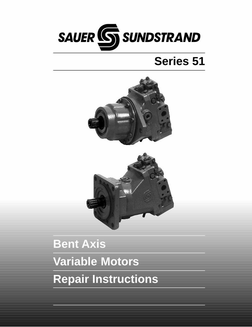
Series 51 MVRepair InstructionsBLN-10044 August 30, 1993Page 2
saue
● When Series 51 units are used in vehicular hydro-static drive systems, the loss of hydrostatic driv-eline power in any mode (forward, reverse, or“neutral” mode) of operation may cause a loss ofhydrostatic braking capacity. A braking system,redundant to the hydrostatic transmission must,therefore, be provided which is adequate to stopand hold the system should the condition de-velop.
● Certain service procedures may require the ve-hicle/machine to be disabled (wheels raised offthe ground, work function disconnected, etc.)while performing them in order to prevent injuryto the technician and bystanders.
● Use caution when dealing with hydraulic fluidunder pressure. Escaping hydraulic fluid underpressure can have sufficient force to penetrateyour skin causing serious injury. This fluid mayalso be hot enough to burn. Serious infection orreactions can develop if proper medical treat-ment is not administered immediately.
● Some cleaning solvents are flammable. To avoidpossible fire, do not use cleaning solvents in anarea where a source of ignition may be present.
Safety Precautions
Genuine Parts Original
Ersatzteile
Series 51 MVRepair InstructionsBLN-10044 August 30, 1993Page 3
saue
Major Repair Instructions — GeneralCAUTION — DISCLAIMER OF LIABILITY
These repair instructions are provided for technicians who have been trained by Sauer-Sundstrand in therepair of Sauer-Sundstrand Series 51 motors. Sauer-Sundstrand recommends that any repairs be performedby Sauer-Sundstrand trained technicians. Sauer-Sundstrand expressly disclaims any liability for workman-ship related failures resulting from repairs performed by any person using these instructions.
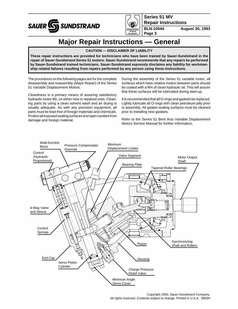
The procedures on the following pages are for the completedisassembly and reassembly (Major Repair) of the Series51 Variable Displacement Motors.
Cleanliness is a primary means of assuring satisfactoryhydraulic motor life, on either new or repaired units. Clean-ing parts by using a clean solvent wash and air drying isusually adequate. As with any precision equipment, allparts must be kept free of foreign materials and chemicals.Protect all exposed sealing surfaces and open cavities fromdamage and foreign material.
During the assembly of the Series 51 variable motor, allsurfaces which have relative motion between parts shouldbe coated with a film of clean hydraulic oil. This will assurethat these surfaces will be lubricated during start-up.
It is recommended that all O-rings and gaskets be replaced.Lightly lubricate all O-rings with clean petroleum jelly priorto assembly. All gasket sealing surfaces must be cleanedprior to installing new gaskets.
Refer to the Series 51 Bent Axis Variable DisplacementMotors Service Manual for further information.
Pressure Compensator Override
Servo Piston Cylinder
Charge Pressure Relief Valve
PistonSynchronizing Shaft and Rollers
Tapered Roller BearingsBearing Plate
Valve SegmentControl (Hydraulic Proportional)
Minimum Displacement Limiter
Motor Output Shaft
Housing
Minimum Angle Servo Cover
End Cap
Control Springs
4-Way Valve and Sleeve
Multi-function Block
Copyright 1993, Sauer-Sundstrand Company.All rights reserved. Contents subject to change. Printed in U.S.A. 0893H
Genuine Parts Original
Ersatzteile
Series 51 MVRepair InstructionsBLN-10044 August 30, 1993Page 4
saue
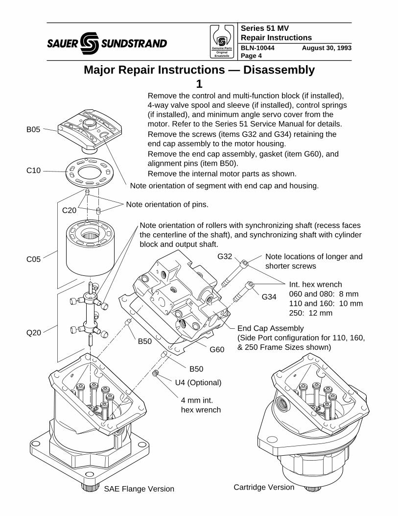
Q20
G60
B50
C05
C10
B05
G34
U4 (Optional)
B50
C20
SAE Flange Version Cartridge Version
4 mm int. hex wrench
Int. hex wrench 060 and 080: 8 mm 110 and 160: 10 mm 250: 12 mm
G32
Note orientation of segment with end cap and housing.
End Cap Assembly (Side Port configuration for 110, 160, & 250 Frame Sizes shown)
Note orientation of rollers with synchronizing shaft (recess faces the centerline of the shaft), and synchronizing shaft with cylinder block and output shaft.
Note locations of longer and shorter screws
Note orientation of pins.
Major Repair Instructions — Disassembly1
Remove the control and multi-function block (if installed),4-way valve spool and sleeve (if installed), control springs(if installed), and minimum angle servo cover from themotor. Refer to the Series 51 Service Manual for details.Remove the screws (items G32 and G34) retaining theend cap assembly to the motor housing.Remove the end cap assembly, gasket (item G60), andalignment pins (item B50).Remove the internal motor parts as shown.
Genuine Parts Original
Ersatzteile
Series 51 MVRepair InstructionsBLN-10044 August 30, 1993Page 5
saue
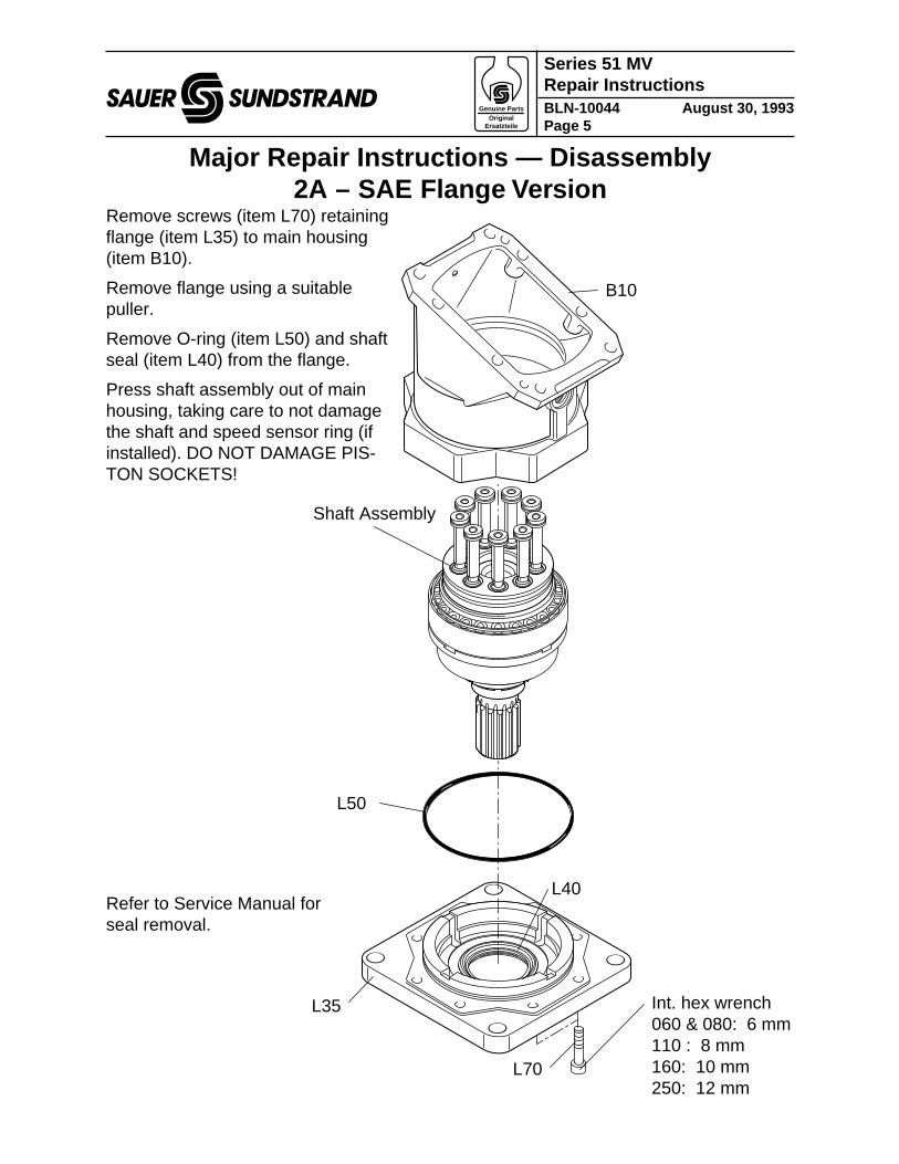
L70
L35
L50
B10
Shaft Assembly
Int. hex wrench 060 & 080: 6 mm 110 : 8 mm 160: 10 mm 250: 12 mm
L40
Major Repair Instructions — Disassembly2A – SAE Flang e Version
Refer to Service Manual forseal removal.
Remove screws (item L70) retainingflange (item L35) to main housing(item B10).
Remove flange using a suitablepuller.
Remove O-ring (item L50) and shaftseal (item L40) from the flange.
Press shaft assembly out of mainhousing, taking care to not damagethe shaft and speed sensor ring (ifinstalled). DO NOT DAMAGE PIS-TON SOCKETS!
Genuine Parts Original
Ersatzteile
Series 51 MVRepair InstructionsBLN-10044 August 30, 1993Page 6
saue
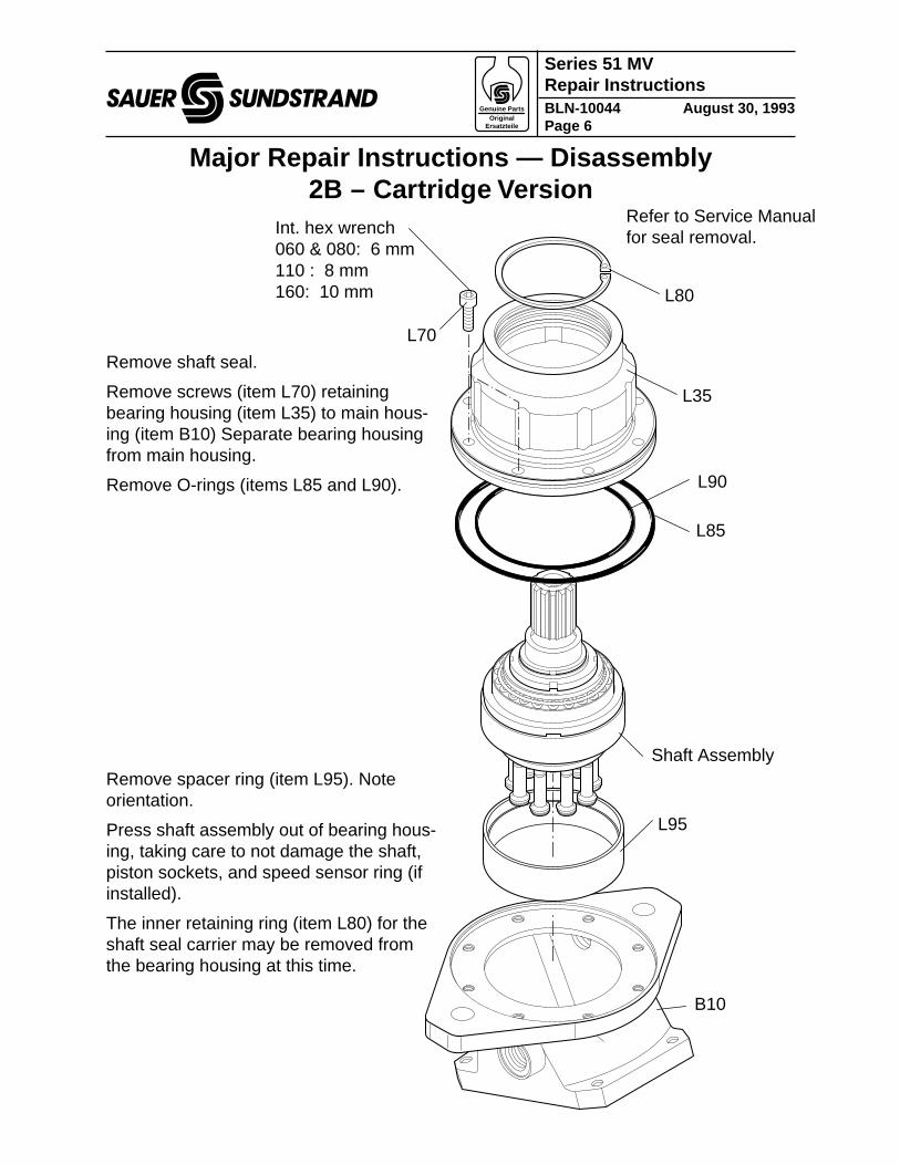
Int. hex wrench 060 & 080: 6 mm 110 : 8 mm 160: 10 mm L80
L35
B10
Shaft Assembly
L95
L70
L90
L85
Major Repair Instructions — Disassembly2B – Car tridge Version
Remove spacer ring (item L95). Noteorientation.
Press shaft assembly out of bearing hous-ing, taking care to not damage the shaft,piston sockets, and speed sensor ring (ifinstalled).
The inner retaining ring (item L80) for theshaft seal carrier may be removed fromthe bearing housing at this time.
Remove shaft seal.
Remove screws (item L70) retainingbearing housing (item L35) to main hous-ing (item B10) Separate bearing housingfrom main housing.
Remove O-rings (items L85 and L90).
Refer to Service Manualfor seal removal.
Genuine Parts Original
Ersatzteile
Series 51 MVRepair InstructionsBLN-10044 August 30, 1993Page 7
saue
F24 (080)
F24 (060)
F30 (060)
F24 (110, 160, 250)
F28
F26
F26
F28
F10
End Cap (Typical for 060 and 080 Frame Sizes) Axial port style shown
End Cap (Typical for 110, 160, and 250 Frame Sizes) Side port style shown
G10
G10
F28
F26
F28
F26
G80
G80A
3 mm int. hex wrench (060) 3 mm int. hex wrench (060)
Int. hex wrench: 060: 3/8 in 080: 9/16 in
5 mm int. hex wrench (080)
5 mm int. hex wrench (110, 160, 250) [4 mm mm int. hex wrench used for very early production motors.]
F10
F10 F12
F12
F12
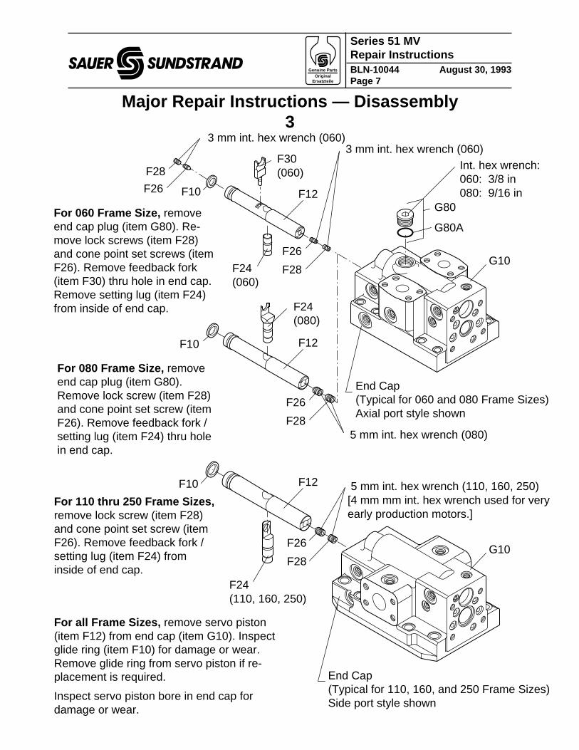
Major Repair Instructions — Disassembly3
For 060 Frame Size, removeend cap plug (item G80). Re-move lock screws (item F28)and cone point set screws (itemF26). Remove feedback fork(item F30) thru hole in end cap.Remove setting lug (item F24)from inside of end cap.
For 080 Frame Size, removeend cap plug (item G80).Remove lock screw (item F28)and cone point set screw (itemF26). Remove feedback fork /setting lug (item F24) thru holein end cap.
For 110 thru 250 Frame Sizes,remove lock screw (item F28)and cone point set screw (itemF26). Remove feedback fork /setting lug (item F24) frominside of end cap.
For all Frame Sizes, remove servo piston(item F12) from end cap (item G10). Inspectglide ring (item F10) for damage or wear.Remove glide ring from servo piston if re-placement is required.
Inspect servo piston bore in end cap fordamage or wear.
Genuine Parts Original
Ersatzteile
Series 51 MVRepair InstructionsBLN-10044 August 30, 1993Page 8
saue
Major Repair Instructions — Reconditioning and Replacement1 – Shaft Assembly
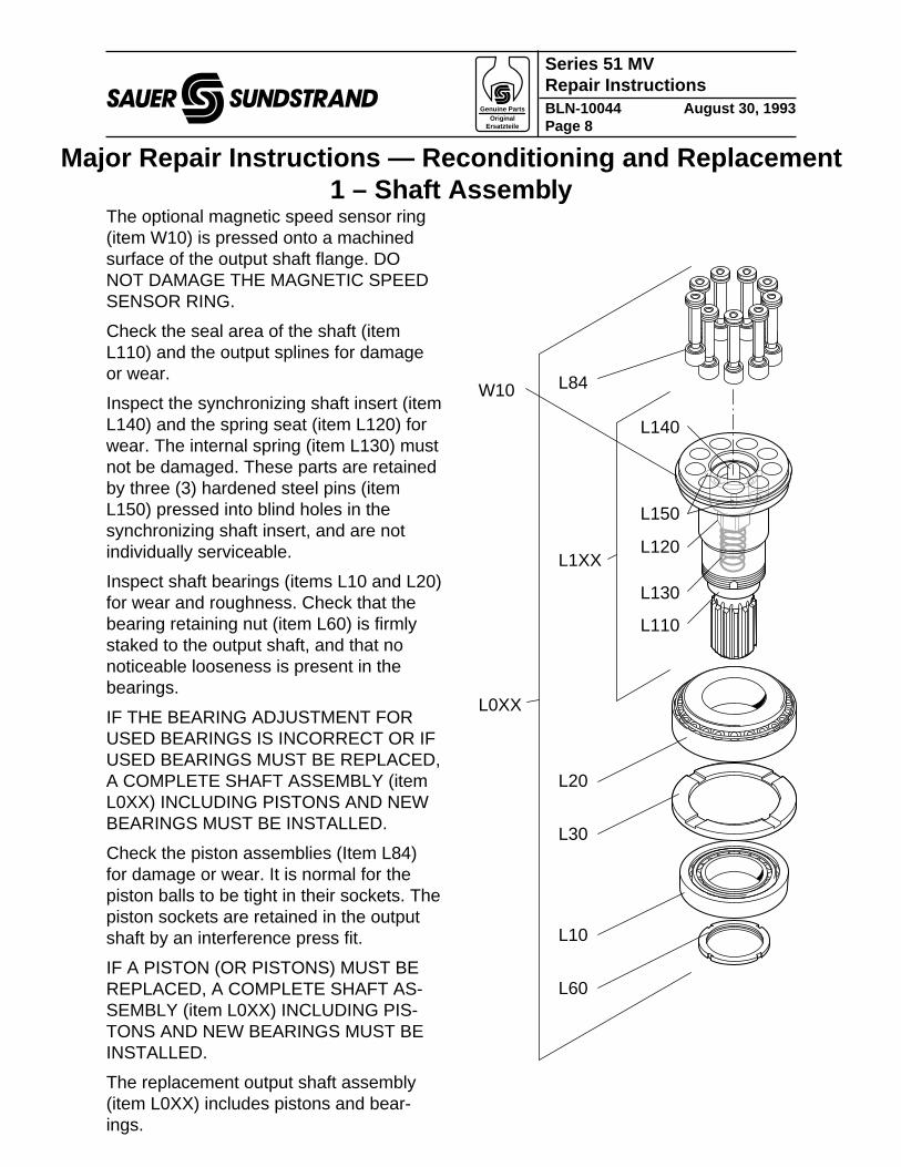
The optional magnetic speed sensor ring(item W10) is pressed onto a machinedsurface of the output shaft flange. DONOT DAMAGE THE MAGNETIC SPEEDSENSOR RING.
Check the seal area of the shaft (itemL110) and the output splines for damageor wear.
Inspect the synchronizing shaft insert (itemL140) and the spring seat (item L120) forwear. The internal spring (item L130) mustnot be damaged. These parts are retainedby three (3) hardened steel pins (itemL150) pressed into blind holes in thesynchronizing shaft insert, and are notindividually serviceable.
Inspect shaft bearings (items L10 and L20)for wear and roughness. Check that thebearing retaining nut (item L60) is firmlystaked to the output shaft, and that nonoticeable looseness is present in thebearings.
IF THE BEARING ADJUSTMENT FORUSED BEARINGS IS INCORRECT OR IFUSED BEARINGS MUST BE REPLACED,A COMPLETE SHAFT ASSEMBLY (itemL0XX) INCLUDING PISTONS AND NEWBEARINGS MUST BE INSTALLED.
Check the piston assemblies (Item L84)for damage or wear. It is normal for thepiston balls to be tight in their sockets. Thepiston sockets are retained in the outputshaft by an interference press fit.
IF A PISTON (OR PISTONS) MUST BEREPLACED, A COMPLETE SHAFT AS-SEMBLY (item L0XX) INCLUDING PIS-TONS AND NEW BEARINGS MUST BEINSTALLED.
The replacement output shaft assembly(item L0XX) includes pistons and bear-ings.
L60
L10
L20
L30
L1XX
W10
L140
L120
L130
L110
L0XX
L84
L150
Genuine Parts Original
Ersatzteile
Series 51 MVRepair InstructionsBLN-10044 August 30, 1993Page 9
saue
�L230
Major Repair Instructions — Reconditioning and Replacement2 – Piston Rings
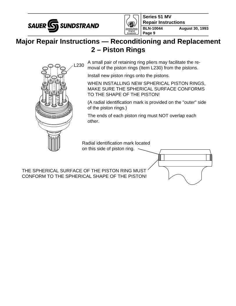
THE SPHERICAL SURFACE OF THE PISTON RING MUSTCONFORM TO THE SPHERICAL SHAPE OF THE PISTON!
A small pair of retaining ring pliers may facilitate the re-moval of the piston rings (Item L230) from the pistons.
Install new piston rings onto the pistons.
WHEN INSTALLING NEW SPHERICAL PISTON RINGS,MAKE SURE THE SPHERICAL SURFACE CONFORMSTO THE SHAPE OF THE PISTON!
(A radial identification mark is provided on the "outer" sideof the piston rings.)
The ends of each piston ring must NOT overlap eachother.
Radial identification mark locatedon this side of piston ring.
Genuine Parts Original
Ersatzteile
Series 51 MVRepair InstructionsBLN-10044 August 30, 1993Page 10
saue
Major Repair Instructions — Reconditioning and Replacement3 – Bearing Plate , Valve Segment, and Cylinder Bloc k
�B05
"A"
C10
"A"
C01
C02
"B"
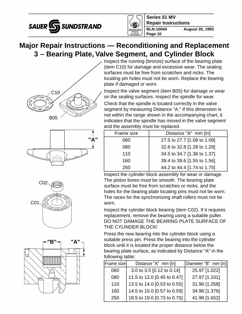
Inspect the running (bronze) surface of the bearing plate(item C10) for damage and excessive wear. The sealingsurfaces must be free from scratches and nicks. Thelocating pin holes must not be worn. Replace the bearingplate if damaged or worn.
Inspect the valve segment (item B05) for damage or wearon the sealing surfaces. Inspect the spindle for wear.Check that the spindle is located correctly in the valvesegment by measuring Distance "A." If this dimension isnot within the range shown in the accompanying chart, itindicates that the spindle has moved in the valve segmentand the assembly must be replaced.
Frame size Distance "A" mm [in]060 27.5 to 27.7 [1.08 to 1.09]
080 32.6 to 32.8 [1.28 to 1.29]110 34.5 to 34.7 [1.36 to 1.37]160 39.4 to 39.6 [1.55 to 1.56]250 44.2 to 44.4 [1.74 to 1.75]
Inspect the cylinder block assembly for wear or damage.The piston bores must be smooth. The bearing platesurface must be free from scratches or nicks, and theholes for the bearing plate locating pins must not be worn.The races for the synchronizing shaft rollers must not beworn.
Inspect the cylinder block bearing (item C02). If it requiresreplacement, remove the bearing using a suitable puller.DO NOT DAMAGE THE BEARING PLATE SURFACE OFTHE CYLINDER BLOCK!Press the new bearing into the cylinder block using asuitable press pin. Press the bearing into the cylinderblock until it is located the proper distance below thebearing plate surface, as indicated by Distance "A" in thefollowing table:Frame size Distance "A" mm [in] Diameter "B" mm [in]
060 3.0 to 3.5 [0.12 to 0.14] 25.97 [1.022]
080 11.5 to 12.0 [0.45 to 0.47] 27.97 [1.101]110 13.5 to 14.0 [0.53 to 0.55] 31.96 [1.258]160 14.5 to 15.0 [0.57 to 0.59] 34.96 [1.376]250 18.5 to 19.0 [0.73 to 0.75] 41.96 [1.652]
Genuine Parts Original
Ersatzteile
Series 51 MVRepair InstructionsBLN-10044 August 30, 1993Page 11
saue
Major Repair Instructions — Assembly1
F24 (080)
F24 (060)
F30 (060)
F28
F26
F26
End Cap (Axial port style shown) Typical for 060 and 080 Frame Sizes
G10
F26
G80
G80A
Torque: (060) 5 Nm [44 lbsf•in]
Torque: (060) 54 Nm [40 lbsf•ft] (080) 95 Nm [70 lbsf•in]
F10
F10F12
F12
Torque: (060) 8.5 Nm [75 lbsf•in]
Multi-function Block / Control
Multi-function Block / Control
Groove
Groove
Lubricate with Hydraulic Oil
Lubricate with Hydraulic Oil
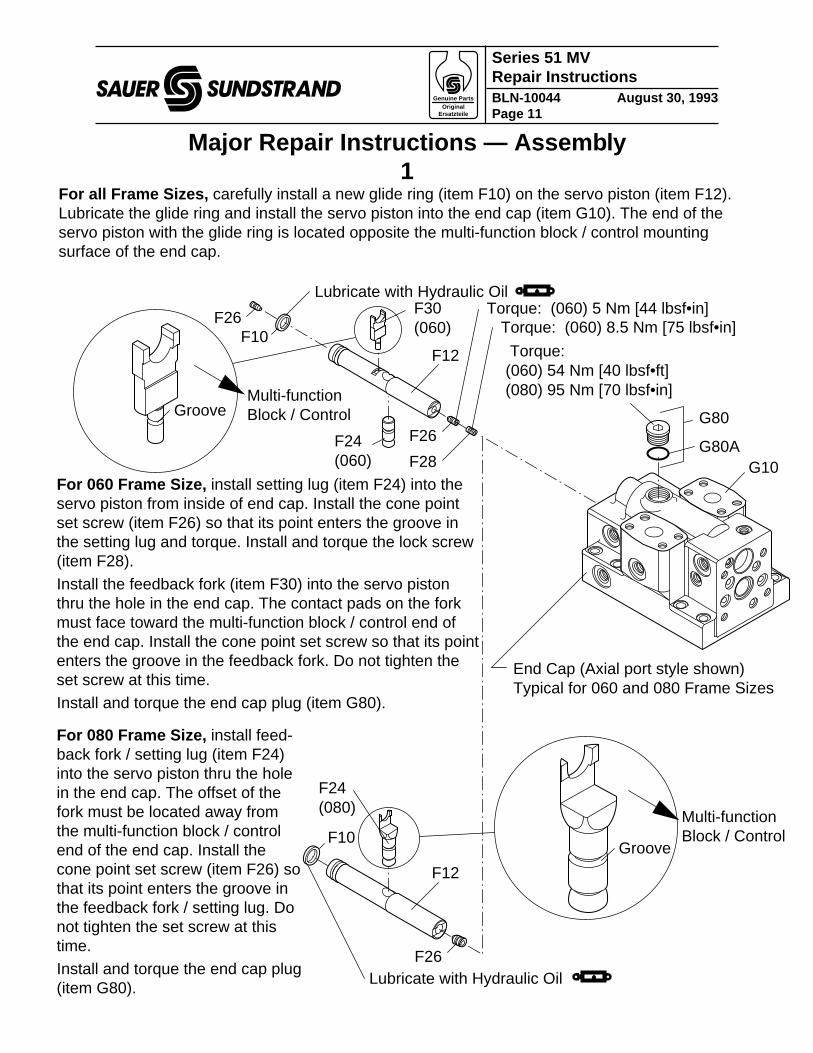
For all Frame Sizes, carefully install a new glide ring (item F10) on the servo piston (item F12).Lubricate the glide ring and install the servo piston into the end cap (item G10). The end of theservo piston with the glide ring is located opposite the multi-function block / control mountingsurface of the end cap.
For 060 Frame Size, install setting lug (item F24) into theservo piston from inside of end cap. Install the cone pointset screw (item F26) so that its point enters the groove inthe setting lug and torque. Install and torque the lock screw(item F28).
Install the feedback fork (item F30) into the servo pistonthru the hole in the end cap. The contact pads on the forkmust face toward the multi-function block / control end ofthe end cap. Install the cone point set screw so that its pointenters the groove in the feedback fork. Do not tighten theset screw at this time.Install and torque the end cap plug (item G80).
For 080 Frame Size, install feed-back fork / setting lug (item F24)into the servo piston thru the holein the end cap. The offset of thefork must be located away fromthe multi-function block / controlend of the end cap. Install thecone point set screw (item F26) sothat its point enters the groove inthe feedback fork / setting lug. Donot tighten the set screw at thistime.Install and torque the end cap plug(item G80).
Genuine Parts Original
Ersatzteile
Series 51 MVRepair InstructionsBLN-10044 August 30, 1993Page 12
saue
F24 (110, 160, 250)
F10
End Cap (Side port style shown) Typical for 110, 160, and 250 Frame Sizes
G10F26
F12Multi-function Block / Control
F28
F28
Torque: (060) 8.5 Nm [75 lbsf•in]
Torque: (080, 110, 160, 250) (M8) 19 Nm [14 lbsf•ft] (M10) 36 Nm [26.5 lbsf•ft]
060 Frame Size 080, 110, 160, 250 Frame Sizes
Groove
Lubricate with Hydraulic Oil
F26 Torque: 5 Nm [44 lbsf•in]
F26 Torque: 5 Nm [44 lbsf•in]
Major Repair Instructions — Assembly2
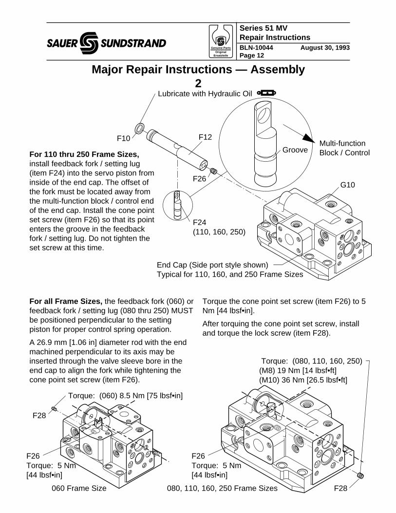
For 110 thru 250 Frame Sizes,install feedback fork / setting lug(item F24) into the servo piston frominside of the end cap. The offset ofthe fork must be located away fromthe multi-function block / control endof the end cap. Install the cone pointset screw (item F26) so that its pointenters the groove in the feedbackfork / setting lug. Do not tighten theset screw at this time.
For all Frame Sizes, the feedback fork (060) orfeedback fork / setting lug (080 thru 250) MUSTbe positioned perpendicular to the settingpiston for proper control spring operation.
A 26.9 mm [1.06 in] diameter rod with the endmachined perpendicular to its axis may beinserted through the valve sleeve bore in theend cap to align the fork while tightening thecone point set screw (item F26).
Torque the cone point set screw (item F26) to 5Nm [44 lbsf•in].
After torquing the cone point set screw, installand torque the lock screw (item F28).
Genuine Parts Original
Ersatzteile
Series 51 MVRepair InstructionsBLN-10044 August 30, 1993Page 13
saue
L35 L50
Shaft Assembly
Torque: 060 & 080: 32 Nm (24 lbsf•ft) 110: 63 Nm (46 lbsf•ft) 160: 110 Nm (81 lbsf•ft) 250: 174 Nm (128 lbsf•ft)
L40Lubricate seal lip with grease.
19°
B10
B10
Housing supported in press. (Side View)
Refer to Service Manual for seal installation.
L70
Major Repair Instructions — Assembly3A – SAE Flang e Version
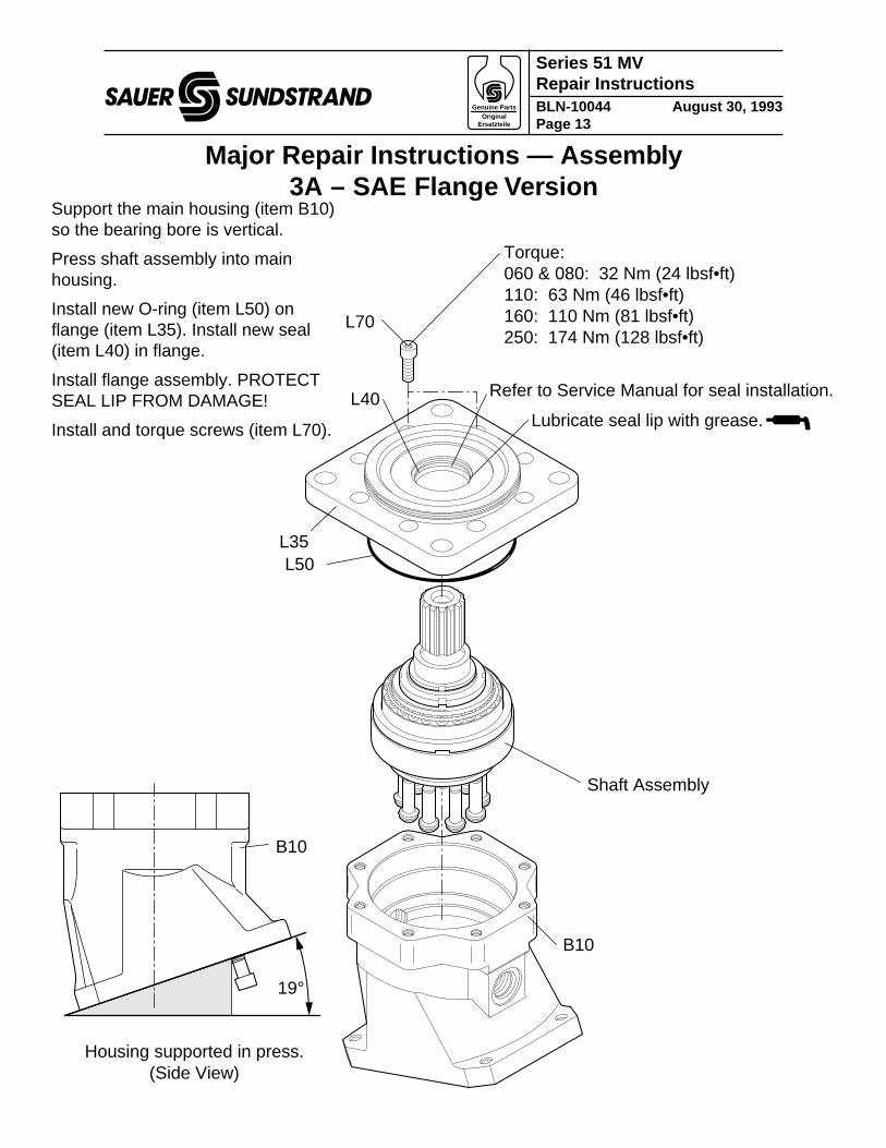
Support the main housing (item B10)so the bearing bore is vertical.
Press shaft assembly into mainhousing.
Install new O-ring (item L50) onflange (item L35). Install new seal(item L40) in flange.
Install flange assembly. PROTECTSEAL LIP FROM DAMAGE!
Install and torque screws (item L70).
Genuine Parts Original
Ersatzteile
Series 51 MVRepair InstructionsBLN-10044 August 30, 1993Page 14
saue
L35
B10
Shaft Assembly
L95
L85
L90
Refer to Service Manual for seal installation.
Torque: 060 & 080: 32 Nm (24 lbsf•ft) 110: 63 Nm (46 lbsf•ft) 160: 110 Nm (81 lbsf•ft)
L80
L70
Major Repair Instructions — Assembly3A – Car tridge Version
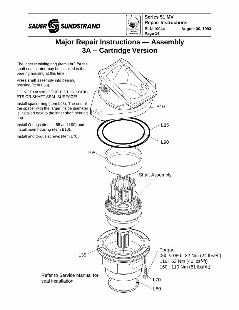
The inner retaining ring (item L80) for theshaft seal carrier may be installed in thebearing housing at this time.
Press shaft assembly into bearinghousing (item L35).
DO NOT DAMAGE THE PISTON SOCK-ETS OR SHAFT SEAL SURFACE!
Install spacer ring (item L95). The end ofthe spacer with the larger inside diameteris installed next to the inner shaft bearingcup.
Install O-rings (items L85 and L90) andinstall main housing (item B10).
Install and torque screws (item L70).
Genuine Parts Original
Ersatzteile
Series 51 MVRepair InstructionsBLN-10044 August 30, 1993Page 15
saue
Q20
Cylinder Block
SAE Flange Version Cartridge Version
C40
C40
C60
C50
C60 C50
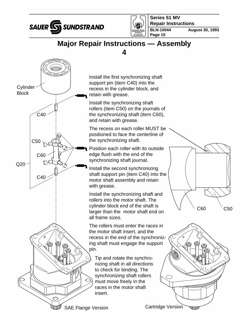
Major Repair Instructions — Assembly4
Install the first synchronizing shaftsupport pin (item C40) into therecess in the cylinder block, andretain with grease.
Install the synchronizing shaftrollers (item C50) on the journals ofthe synchronizing shaft (item C60),and retain with grease.
The recess on each roller MUST bepositioned to face the centerline ofthe synchronizing shaft.
Position each roller with its outsideedge flush with the end of thesynchronizing shaft journal.
Install the second synchronizingshaft support pin (item C40) into themotor shaft assembly and retainwith grease.
Install the synchronizing shaft androllers into the motor shaft. Thecylinder block end of the shaft islarger than the motor shaft end onall frame sizes.
The rollers must enter the races inthe motor shaft insert, and therecess in the end of the synchroniz-ing shaft must engage the supportpin.
Tip and rotate the synchro-nizing shaft in all directionsto check for binding. Thesynchronizing shaft rollersmust move freely in theraces in the motor shaftinsert.
Genuine Parts Original
Ersatzteile
Series 51 MVRepair InstructionsBLN-10044 August 30, 1993Page 16
saue
Cylinder Block
Pistons
C40
C50
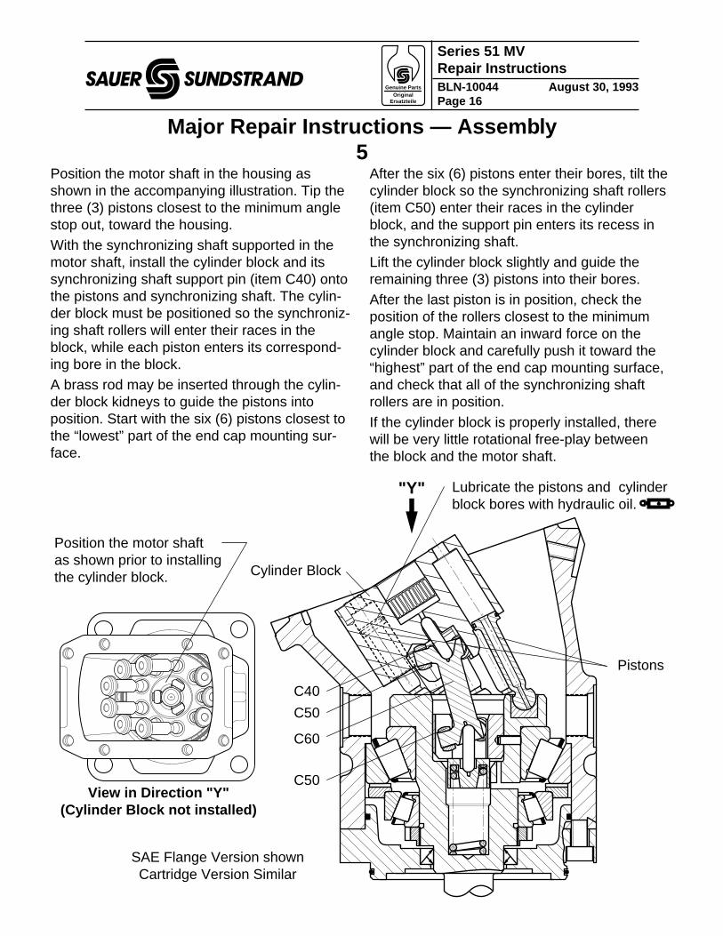
Lubricate the pistons and cylinder block bores with hydraulic oil.
C60
C50View in Direction "Y"
(Cylinder Block not installed)
"Y"
Position the motor shaft as shown prior to installing the cylinder block.
SAE Flange Version shown Cartridge Version Similar
Major Repair Instructions — Assembly5
Position the motor shaft in the housing asshown in the accompanying illustration. Tip thethree (3) pistons closest to the minimum anglestop out, toward the housing.With the synchronizing shaft supported in themotor shaft, install the cylinder block and itssynchronizing shaft support pin (item C40) ontothe pistons and synchronizing shaft. The cylin-der block must be positioned so the synchroniz-ing shaft rollers will enter their races in theblock, while each piston enters its correspond-ing bore in the block.A brass rod may be inserted through the cylin-der block kidneys to guide the pistons intoposition. Start with the six (6) pistons closest tothe “lowest” part of the end cap mounting sur-face.
After the six (6) pistons enter their bores, tilt thecylinder block so the synchronizing shaft rollers(item C50) enter their races in the cylinderblock, and the support pin enters its recess inthe synchronizing shaft.Lift the cylinder block slightly and guide theremaining three (3) pistons into their bores.After the last piston is in position, check theposition of the rollers closest to the minimumangle stop. Maintain an inward force on thecylinder block and carefully push it toward the“highest” part of the end cap mounting surface,and check that all of the synchronizing shaftrollers are in position.
If the cylinder block is properly installed, therewill be very little rotational free-play betweenthe block and the motor shaft.
Genuine Parts Original
Ersatzteile
Series 51 MVRepair InstructionsBLN-10044 August 30, 1993Page 17
saue
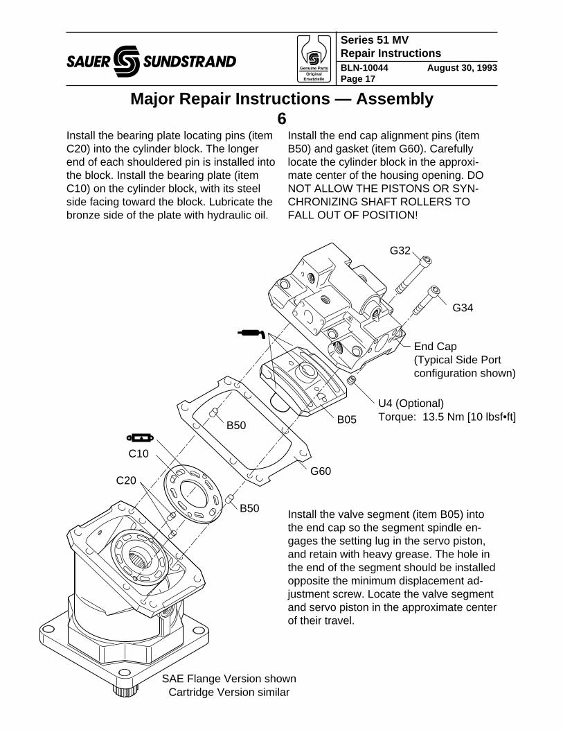
Major Repair Instructions — Assembly6
B50
C10
B05
G34
U4 (Optional) Torque: 13.5 Nm [10 lbsf•ft]
B50
C20
SAE Flange Version shown Cartridge Version similar
G32
End Cap (Typical Side Port configuration shown)
G60
Install the bearing plate locating pins (itemC20) into the cylinder block. The longerend of each shouldered pin is installed intothe block. Install the bearing plate (itemC10) on the cylinder block, with its steelside facing toward the block. Lubricate thebronze side of the plate with hydraulic oil.
Install the end cap alignment pins (itemB50) and gasket (item G60). Carefullylocate the cylinder block in the approxi-mate center of the housing opening. DONOT ALLOW THE PISTONS OR SYN-CHRONIZING SHAFT ROLLERS TOFALL OUT OF POSITION!
Install the valve segment (item B05) intothe end cap so the segment spindle en-gages the setting lug in the servo piston,and retain with heavy grease. The hole inthe end of the segment should be installedopposite the minimum displacement ad-justment screw. Locate the valve segmentand servo piston in the approximate centerof their travel.
Genuine Parts Original
Ersatzteile
Series 51 MVRepair InstructionsBLN-10044 August 30, 1993Page 18
saue
G34
SAE Flange Version shown Cartridge Version similar
G32
End cap assembly with valve segment
"Double-X" Pattern Torquing Sequence
(110 Frame Size with Side Port Endcap shown)
1 / 9 4 / 12 8 / 166 / 14
3 / 11 2 / 10 5 / 137 / 15
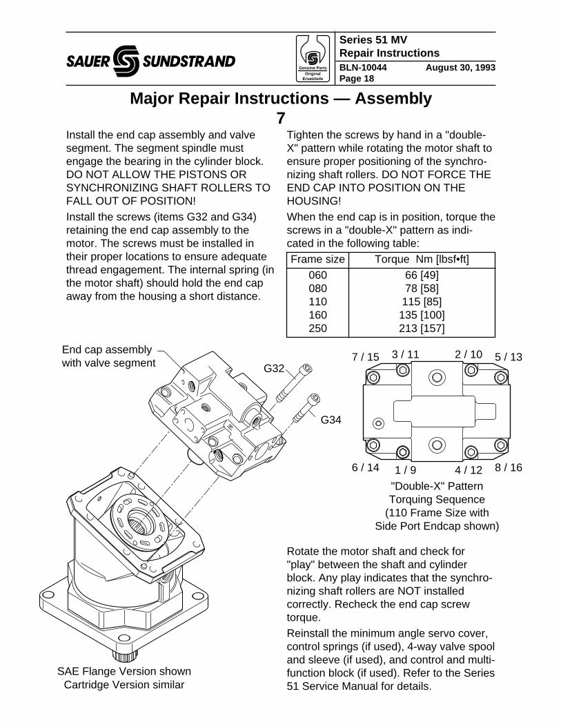
Major Repair Instructions — Assembly7
Install the end cap assembly and valvesegment. The segment spindle mustengage the bearing in the cylinder block.DO NOT ALLOW THE PISTONS ORSYNCHRONIZING SHAFT ROLLERS TOFALL OUT OF POSITION!Install the screws (items G32 and G34)retaining the end cap assembly to themotor. The screws must be installed intheir proper locations to ensure adequatethread engagement. The internal spring (inthe motor shaft) should hold the end capaway from the housing a short distance.
Tighten the screws by hand in a "double-X" pattern while rotating the motor shaft toensure proper positioning of the synchro-nizing shaft rollers. DO NOT FORCE THEEND CAP INTO POSITION ON THEHOUSING!When the end cap is in position, torque thescrews in a "double-X" pattern as indi-cated in the following table:Frame size Torque Nm [lbsf•ft]
060 66 [49]080 78 [58]110 115 [85]160 135 [100]250 213 [157]
Rotate the motor shaft and check for"play" between the shaft and cylinderblock. Any play indicates that the synchro-nizing shaft rollers are NOT installedcorrectly. Recheck the end cap screwtorque.Reinstall the minimum angle servo cover,control springs (if used), 4-way valve spooland sleeve (if used), and control and multi-function block (if used). Refer to the Series51 Service Manual for details.
Genuine Parts Original
Ersatzteile
Series 51 MVRepair InstructionsBLN-10044 August 30, 1993Page 19
saue
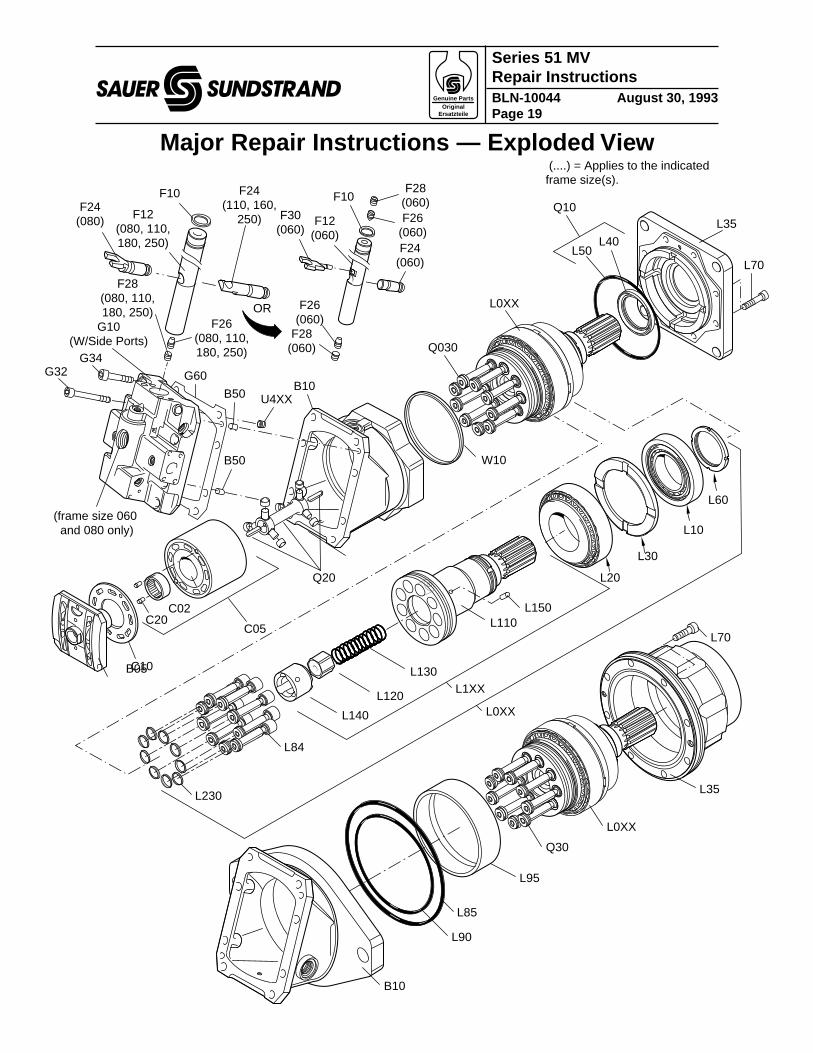
Major Repair Instructions — Exploded View
L60
L10
L20
L30
L1XX
L140
L120
L130
L150
W10
L110
L0XX
L70
L35
L40 L50
B10
Q20
G60
B50
C05
C10B05
G34G32
U4XX
B50
Q030
Q10
L0XX
G10 (W/Side Ports)
(....) = Applies to the indicated frame size(s).
F24 (110, 160,
250)F12 (080, 110, 180, 250)
F26 (080, 110, 180, 250)
F28 (080, 110, 180, 250)
F24 (080)
F24 (060)
F12 (060)
F26 (060)
F28 (060)
F30 (060)
F28 (060)F26
(060)
F10 F10
OR
(frame size 060 and 080 only)
L84
�L230 L35
B10
L95
L70
L85
L90
Q30
L0XX
C02C20
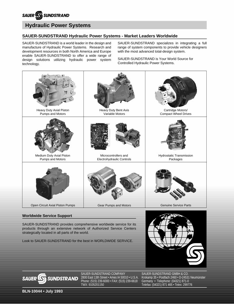
SAUER-SUNDSTRAND Hydraulic Power Systems - Market Leaders Worldwide
SAUER-SUNDSTRAND specializes in integrating a fullrange of system components to provide vehicle designerswith the most advanced total-design system.
SAUER-SUNDSTRAND is Your World Source forControlled Hydraulic Power Systems.
SAUER-SUNDSTRAND is a world leader in the design andmanufacture of Hydraulic Power Systems. Research anddevelopment resources in both North America and Europeenable SAUER-SUNDSTRAND to offer a wide range ofdesign solutions utilizing hydraulic power systemtechnology.
saue
Worldwide Service Support
SAUER-SUNDSTRAND provides comprehensive worldwide service for itsproducts through an extensive network of Authorized Service Centersstrategically located in all parts of the world.
Look to SAUER-SUNDSTRAND for the best in WORLDWIDE SERVICE.
Genuine Service PartsGear Pumps and MotorsOpen Circuit Axial Piston Pumps
Hydraulic Power Systems
Cartridge Motors/Compact Wheel Drives
Heavy Duty Bent AxisVariable Motors
Heavy Duty Axial PistonPumps and Motors
Hydrostatic TransmissionPackages
Medium Duty Axial PistonPumps and Motors
Microcontrollers andElectrohydraulic Controls
saue
BLN-10044 • July 1993
SAUER-SUNDSTRAND COMPANY2800 East 13th Street • Ames IA 50010 • U.S.A.Phone: (515) 239-6000 • FAX: (515) 239-6618TWX: 9105201150
SAUER-SUNDSTRAND GMBH & CO.Krokamp 35 • Postfach 2460 • D-24531 NeumünsterGermany • Telephone: (04321) 871-0Telefax: (04321) 871 465 • Telex: 299776