Embed Size (px)
Citation preview
Series 51 Series 51-1Bent Axis Variable Dis-placementMotors
TechnicalInformation
2 520L0440 • Rev AE • Dec 2010
Series 51 and 51-1 Bent Axis Variable Displacement MotorsTechnical Information
Series 51 and 51-1 variable displacement motors are bent axis design units, incorporat-ing spherical pistons.
These motors are designed primarily to be combined with other products in closed cir-cuit systems to transfer and control hydraulic power. Series 51 and 51-1 motors havea large maximum / minimum displacement ratio (5:1) and high output speed capabili-ties. SAE, cartridge, and DIN flange configurations are available.
A complete family of controls and regulators is available to fulfill the requirements ofa wide range of applications. Motors normally start at maximum displacement. This provides maximum starting torque for high acceleration.
The controls may utilize internally supplied servo pressure. They may be overridden bya pressure compensator which functions when the motor is operating in motor and pump modes. A defeat option is available to disable the pressure compensator override when the motor is running in pump mode.
The pressure compensator option features a low pressure rise (short ramp) to ensure optimal power utilization throughout the entire displacement range of the motor.The pressure compensator is also available as a stand-alone regulator.
• The series 51 and 51-1 motors – Advanced technology today
• The most technically advanced hydraulic units in the industry
• SAE, cartridge, and DIN flange motors
• Cartridge motors designed for direct installation in compact planetary drives
• Large displacement ratio (5:1)
• Complete family of control systems
• Proven reliability and performance
• Optimum product configurations
• Compact, lightweight
© 2009, Sauer-Danfoss
Sauer-Danfoss can accept no responsibility for possible errors in catalogues, brochures and other printed material. Sauer -Danfoss reserves the right to alter its products without prior notice. This also applies to products already ordered provided that such alterations can be made without subsequent changes being necessary in specifications already agreed. All trademarks in this material are properties of the respective companies. Sauer-Danfoss and the Sauer-Danfoss logotype are trademarks of the Sauer-Danfoss Group. All rights reserved.
Front page: F300550, F300542, F300541, F300549, P001196-2
General Description
General Description
3520L0440 • Rev AE • Dec 2010
Series 51 and 51-1 Bent Axis Variable Displacement MotorsTechnical Information
General Description ........................................................................................................................2Sectional View ..................................................................................................................................6
Series 51-1, Two-Position Control ...........................................................................................................................6Series 51, Proportional Control ...............................................................................................................................7
System Circuit Description ..............................................................................................................8Pictorial Diagram ..........................................................................................................................................................8System Circuit Diagram ..............................................................................................................................................8
Technical Specifications ................................................................................................................10General specifications ............................................................................................................................................. 10Specific Data ............................................................................................................................................................... 10Fluid Specifications ................................................................................................................................................... 11Determination of Nominal Motor Sizes ............................................................................................................ 12
General Technical Specifications ..................................................................................................13Case Pressure .............................................................................................................................................................. 13Speed Range ............................................................................................................................................................... 13Pressure Limits ........................................................................................................................................................... 14Loop Flushing ............................................................................................................................................................. 14Minimum Displacement Limiter ......................................................................................................................... 16Hydraulic Fluids ......................................................................................................................................................... 16Temperature and Viscosity ..................................................................................................................................... 16Fluid and Filtration .................................................................................................................................................... 17Independent Braking System ............................................................................................................................... 18Reservoir ....................................................................................................................................................................... 18Motor Bearing Life .................................................................................................................................................... 19External Shaft Loads ................................................................................................................................................. 20External Shaft Loads Orientation ......................................................................................................................... 20Allowable External Shaft Load, when Shaft Load Distance is different from Standard ................... 22Efficiency Graphs and Maps .................................................................................................................................. 23Speed Sensor .............................................................................................................................................................. 25
Typical Control and Regulator Applications ...............................................................................26Controls Circuit Diagram – Nomenclature – Description .........................................................28
Hydraulic Two-Position Control – Option N1NN for 51-1 – Frame Size 060, 080, 110 ...................... 28Hydraulic Two-Position Control – Option HZB1 for 51 – Frame Size 160, 250 .................................... 29Pressure Compensator Control – Options TA** for 51-1 – Frame Size 060, 080, 110 ....................... 30Pressure Compensator Control – Options TA** for 51 – Frame Size 160, 250 ..................................... 33Hydraulic Two-Position Control – Options TH** for 51-1 – Frame Size 060, 080, 110 ...................... 35Hydraulic Two-Position Control – Options TH** for 51 – Frame Size 160, 250.................................... 38Electrohydraulic Two-Position Control – Options E1B1, E2B1, E7B1 for 51-1Frame Size 060, 080, 110......................................................................................................................................... 40Electrohydraulic Two-Position Control – Options E1A5, E2A5 for 51 – Frame Size 160, 250 ......... 42Electrohydraulic Two-Position Control – Options F1B1, F2B1 for 51-1Frame Size 060, 080, 110 ........................................................................................................................................ 43Electrohydraulic Two-Position Control – Options F1A5, F2A5 for 51 – Frame Size 160, 250 ......... 45Electrohydraulic Two-Position Control – Options T1**, T2**, T7** for 51-1Frame Size 060, 080, 110 ...................................................................................................................................... 46Electrohydraulic Two-Position Control – Options T1**, T2** for 51 – Frame Size 160, 250 .......... 49Electrohydraulic Proportional Control – Options EP**, EQ** for 51Frame Size 060, 080, 110, 160, 250 .................................................................................................................... 52Electrohydraulic Proportional Control – Options L1B1, L2B1, L7B1 for 51Frame Size 060, 080, 110, 160, 250 ..................................................................................................................... 55Electrohydraulic Proportional Control – Options D7M1, D8M1 for 51Frame Size 060, 080, 110, 160, 250 ...................................................................................................................... 56
Contents
Contents
4 520L0440 • Rev AE • Dec 2010
Series 51 and 51-1 Bent Axis Variable Displacement MotorsTechnical Information
Hydraulic Proportional Control – Options HS** for 51, Frame Size 060, 080, 110, 160, 250 .......... 58 Hydraulic Proportional Control – Option HZB1 for 51, Frame Size 060, 080, 110, 160, 250 .......... 60
General Dimensions – Frame Size 060 .........................................................................................62SAE Flange Design per ISO 3019/1 ..................................................................................................................... 62
51V060-1 Two Position Control, N1NN ........................................................................................................ 6251V060 Proportional and Two-Position Control, HZB1 ......................................................................... 63Shaft Options – 51V060-1 and 51V060 ....................................................................................................... 64
DIN Flange Design per ISO 3019/2...................................................................................................................... 6551D060-1 Two Position Control, N1NN ....................................................................................................... 6551D060 Proportional and Two-Position Control, HZB1 ......................................................................... 66Shaft Options – 51D060-1 and 51D060 ...................................................................................................... 67
Cartridge Flange ........................................................................................................................................................ 6851C060-1 Two Position Control, N1NN ........................................................................................................ 6851C060 Proportional and Two-Position Control, HZB1 ......................................................................... 69Shaft Options – 51C060-1 and 51C060 ....................................................................................................... 70
General Dimensions – Frame Size 080 .........................................................................................71SAE Flange Design per ISO 3019/1 ..................................................................................................................... 71
51V080-1 Two Position Control, N1NN ........................................................................................................ 7151V080 Proportional and Two-Position Control, HZB1 ......................................................................... 72Shaft Options – 51V080-1 and 51V080 ....................................................................................................... 73
DIN Flange Design per ISO 3019/2...................................................................................................................... 7451D080-1 Two Position Control, N1NN ...................................................................................................... 7451D080 Proportional and Two-Position Control, HZB1 ......................................................................... 75Shaft Options – 51D080-1 and 51D080 ...................................................................................................... 76
Cartridge Flange ........................................................................................................................................................ 7751C080-1 Two Position Control, N1NN ........................................................................................................ 7751C080 Proportional and Two-Position Control, HZB1 ......................................................................... 78Shaft Options – 51C080-1 and 51C080 ....................................................................................................... 79
General Dimensions – Frame Size 110 .........................................................................................80SAE Flange Design per ISO 3019/1 ..................................................................................................................... 80
51V110-1 Two Position Control, N1NN ........................................................................................................ 8051V110 Proportional and Two-Position Control, HZB1 ......................................................................... 81Shaft Options – 51V110-1 and 51V110 ....................................................................................................... 82
DIN Flange Design per ISO 3019/2...................................................................................................................... 8351D110-1 Two Position Control, N1NN ....................................................................................................... 8351D110 Proportional and Two-Position Control, HZB1 ......................................................................... 84Shaft Options – 51D110-1 and 51D110 ...................................................................................................... 85
Cartridge Flange ........................................................................................................................................................ 8651C110-1 Two Position Control, N1NN ........................................................................................................ 8651C110 Proportional and Two-Position Control, HZB1 ......................................................................... 87Shaft Options – 51C110-1 and 51C110 ....................................................................................................... 88
General Dimensions – Frame Size 160 .........................................................................................90SAE Flange Design per ISO 3019/1 ..................................................................................................................... 90
51V160 Proportional and Two-Position Control, HZB1 ......................................................................... 90Shaft Options – 51V160 .................................................................................................................................... 91
DIN Flange Design per ISO 3019/2...................................................................................................................... 9251D160 Proportional and Two-Position Control, HZB1 ......................................................................... 92Shaft Options – 51D160 ................................................................................................................................... 93
Cartridge Flange ........................................................................................................................................................ 9451C160 Proportional and Two-Position Control, HZB1 ......................................................................... 94Shaft Options – 51C160 .................................................................................................................................... 95
Contents
Contents(continued)
5520L0440 • Rev AE • Dec 2010
Series 51 and 51-1 Bent Axis Variable Displacement MotorsTechnical Information
General Dimensions – Frame Size 250 .........................................................................................96SAE Flange Design per ISO 3019/1 ..................................................................................................................... 96
51V250 Proportional and Two-Position Control, HZB1 ......................................................................... 96Shaft Options – 51V250 .................................................................................................................................... 97
Dimension – Controls ....................................................................................................................98Pressure Compensator Control – Options TA** for 51-1 – Frame Size 060, 080, 110 ....................... 98Pressure Compensator Control – Options TA** for 51 – Frame Size 160, 250 ..................................... 99Hydraulic Two-Position Control – Options TH** for 51-1 – Frame Size 060, 080, 110 ....................100Hydraulic Two-Position Control – Options TH** for 51 – Frame Size 160, 250 .................................101Electrohydraulic Two-Position Control – Options E1B1, E2B1, E7B1, F1B1, F2B1 for 51-1Frame Size 060, 080, 110.......................................................................................................................................102Electrohydraulic Two-Position Control – Options E1A5, E2A5, F1A5, F2A5 for 51Frame Size 160, 250 ................................................................................................................................................103Electrohydraulic Two-Position Control – Options T1**, T2**, T7** for 51-1Frame Size 060, 080, 110.......................................................................................................................................104Electrohydraulic Two-Position Control – Options T1C2, T2C2 for 51 – Frame Size 160, 250 .......105Electrohydraulic Proportional Control – Options EPA1, EQA1 for 51Frame Size 060, 080, 110, 160, 250 ....................................................................................................................106Electrohydraulic Proportional Control – Options L1B1, L2B1, L7B1 for 51Frame Size 060,080, 110, 160, 250 .....................................................................................................................107Electrohydraulic Proportional Control – Options D7M1, D8M1 for 51Frame Size 060, 080, 110.......................................................................................................................................108Electrohydraulic Proportional Control – Options D7M1, D8M1 for 51 – Frame Size 160, 250 ....109Hydraulic Proportional Control – Options HSA* for 51 – Frame Size 060,080, 110, 160, 250 ......110Hydraulic Proportional Control – Option HZB1 for 51 – Frame Size 060,080, 110, 160, 250 .......111
Contents
Contents(continued)
6 520L0440 • Rev AE • Dec 2010
Series 51 and 51-1 Bent Axis Variable Displacement MotorsTechnical Information
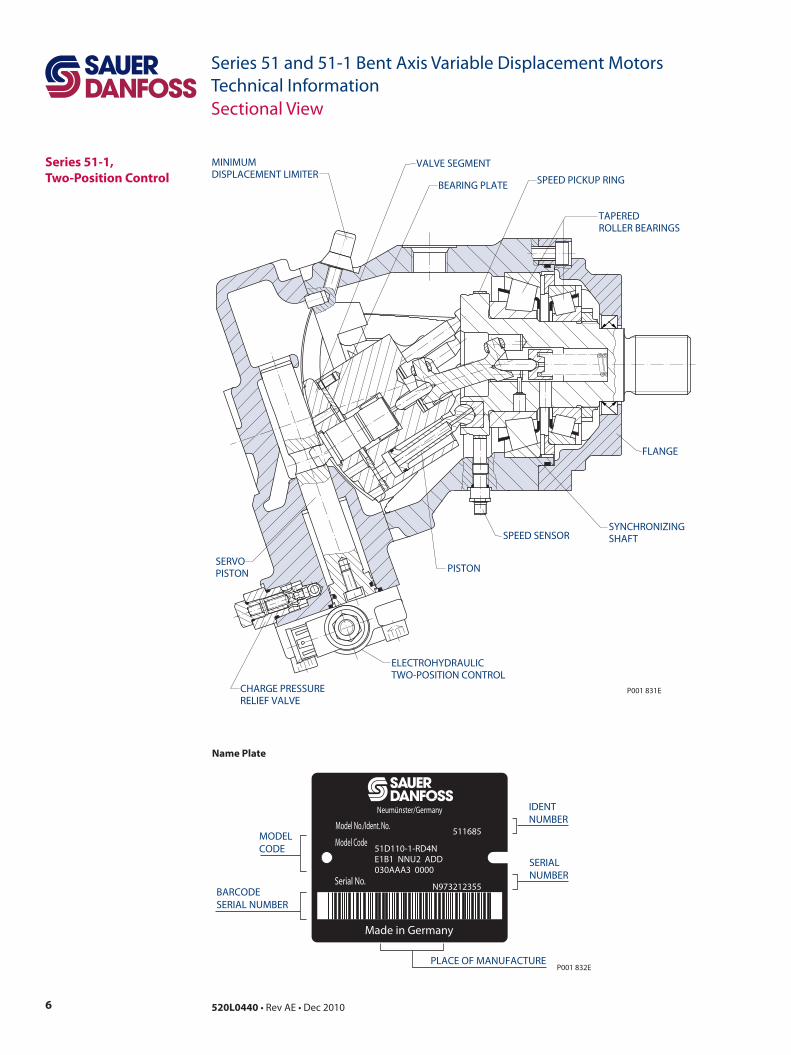
Series 51-1,Two-Position Control
SERVOPISTON
CHARGE PRESSURERELIEF VALVE
PISTON
SYNCHRONIZINGSHAFT
TAPEREDROLLER BEARINGS
SPEED PICKUP RINGBEARING PLATE
VALVE SEGMENTMINIMUMDISPLACEMENT LIMITER
P001 831E
FLANGE
ELECTROHYDRAULICTWO-POSITION CONTROL
SPEED SENSOR
Name Plate
Sectional View
Made in Germany
Serial No.
Model Code
Model No./Ident. No.
Neumünster/Germany
PLACE OF MANUFACTURE
IDENTNUMBER
SERIALNUMBER
MODELCODE
BARCODESERIAL NUMBER
P001 832E
511685
51D110-1-RD4NE1B1 NNU2 ADD030AAA3 0000
N973212355
7520L0440 • Rev AE • Dec 2010
Series 51 and 51-1 Bent Axis Variable Displacement MotorsTechnical Information
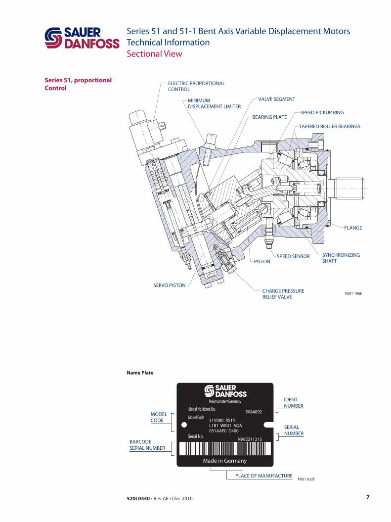
Series 51, proportional Control
SERVO PISTONCHARGE PRESSURERELIEF VALVE
PISTONSYNCHRONIZINGSHAFT
TAPERED ROLLER BEARINGS
BEARING PLATE
VALVE SEGMENT
ELECTRIC PROPORTIONALCONTROL
MINIMUMDISPLACEMENT LIMITER
P001 196E
SPEED PICKUP RING
FLANGE
SPEED SENSOR
Sectional View
Name Plate
Made in Germany
Serial No.
Model Code
Model No./Ident. No.
Neumünster/Germany
PLACE OF MANUFACTURE
IDENTNUMBER
SERIALNUMBER
MODELCODE
BARCODESERIAL NUMBER
P001 832E
5084092
51V080 RS1NL1B1 WB31 ADA051AAF0 D400
N982211215
8 520L0440 • Rev AE • Dec 2010
Series 51 and 51-1 Bent Axis Variable Displacement MotorsTechnical Information
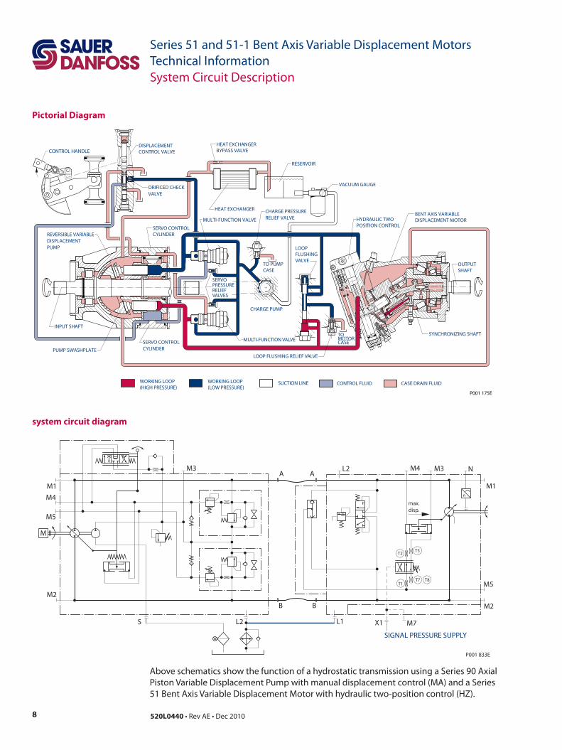
Pictorial Diagram
system circuit diagram
Above schematics show the function of a hydrostatic transmission using a Series 90 Axial Piston Variable Displacement Pump with manual displacement control (MA) and a Series 51 Bent Axis Variable Displacement Motor with hydraulic two-position control (HZ).
System Circuit Description
MULTI-FUNCTION VALVESYNCHRONIZING SHAFT
PUMP SWASHPLATE
SERVO CONTROL CYLINDER
SERVO CONTROL CYLINDER
REVERSIBLE VARIABLE DISPLACEMENTPUMP
INPUT SHAFT
HEAT EXCHANGER
LOOPFLUSHINGVALVE
CHARGE PUMP
ORIFICED CHECKVALVE
MULTI-FUNCTION VALVE
CHARGE PRESSURERELIEF VALVE
SERVOPRESSURERELIEFVALVES
TOMOTORCASE
TO PUMPCASE
P001 175E
CONTROL HANDLEDISPLACEMENT CONTROL VALVE
HEAT EXCHANGER BYPASS VALVE
RESERVOIR
VACUUM GAUGE
HYDRAULIC TWOPOSITION CONTROL
BENT AXIS VARIABLE DISPLACEMENT MOTOR
OUTPUTSHAFT
CONTROL FLUID CASE DRAIN FLUIDSUCTION LINEWORKING LOOP(HIGH PRESSURE)
WORKING LOOP(LOW PRESSURE)
LOOP FLUSHING RELIEF VALVE
max.disp.
T1T7 T8
T2T3
M
M7
SIGNAL PRESSURE SUPPLY
X1L1
BB
L2
M2
M1
M4
M5
M3 L2 M4 M3 N
M1
M5
M2
A A
S
n
P001 833E

9520L0440 • Rev AE • Dec 2010
Series 51 and 51-1 Bent Axis Variable Displacement MotorsTechnical InformationNotes
10 520L0440 • Rev AE • Dec 2010
Series 51 and 51-1 Bent Axis Variable Displacement MotorsTechnical Information
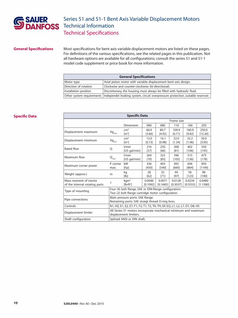
General Specifications Most specifications for bent axis variable displacement motors are listed on these pages. For definitions of the various specifications, see the related pages in this publication. Not all hardware options are available for all configurations; consult the series 51 and 51-1 model code supplement or price book for more information.
Specific Data
Technical Specifications
epytrotoM .ngisedsixatnebtnemecalpsidelbairavhtiwrotomnotsiplaixA
noitatorfonoitceriD .)lanoitcerid-ib(esiwkcolc-retnuocdnaesiwkcolC
noitisopnoitallatsnI .diulfciluardyhhtiwdellifebsyawlatsumgnisuoheht,yranoitercsiD
stnemeriuqermetsysrehtO .riovreserelbatius,noitcetorperusserprevotiucric,metsysgnikarbtednepednI
General Specifications
ezisemarF
noisnemiD 060 080 011 061 052
mumixamtnemecalpsiD gVxam
mc 3
ni[ 3]0.06
]66.3[7.08
]29.4[9.901]17.6[
9.061]28.9[
0.052]62.51[
muminimtnemecalpsiD gVnim
mc 3
ni[ 3]0.21
]37.0[1.61
]89.0[0.22
]43.1[2.23
]69.1[0.05
]50.3[
wolfdetaR Qnim/l
]nim/lagSU[612]75[
052]66[
803]18[
204]601[
055]541[
wolfmumixaM Qxam
nim/l]nim/lagSU[
462]07[
323]58[
693]501[
515]631[
576]871[
rewoprenrocmumixaMrenrocP
.xamWk
]ph[633
]054[304
]045[294
]066[446
]468[058
]0411[
).xorppa(thgieW mgk
]bl[82
]26[23
]17[44
]79[65
]321[68
]091[
aitrenifotnemomssaMstrapgnitatorlanretniehtfo
Jmgk 2
tf•bl[ 2]6400.0
]2901.0[1700.0
]5861.0[8210.0
]7303.0[4320.0
]3555.0[0840.0
]0851.1[
gnitnuomfoepyT.noitarugifnocegnalf-NIDroEAS,egnalftlob)4(ruoF
.noitarugifnocrotomegdirtracegnalftlob)2(owT
snoitcennocepiP.egnalf-EAS:stroperusserpniaM
.ssobgnir-OdaerhttgiartsEAS:stropgniniameR
slortnoC SH,8D,7D,7L,2L,1L,QE,PE,HT,AT,2T,1T,2F,1F,7E,2E,1E,ZH,1N
retimiltnemecalpsiDmumixamdnamuminimlacinahcemetaroprocnisrotom15seireSllA
.sretimiltnemecalpsid
noitarugifnoctfahS .tfahsNIDroISNAdenilpS
Specific Data
11520L0440 • Rev AE • Dec 2010
Series 51 and 51-1 Bent Axis Variable Displacement MotorsTechnical InformationTechnical Specifications
Specific Data(continued)
Fluid Specifications
nim 1- )mpr(
ezisemarF 060 080 011 061 052
deepsdetaR.psid.xamta.psid.nimta
00630065
00130005
00820054
00520004
00220043
deepsmumixaM )1 .psid.xamta.psid.nimta
00440007
00040526
00630065
00230005
00720524
)1 neewtebstnemecalpsidtadeeps.xamrofevitatneserperssofnaD-reuaSruoytcatnoC.tnemecalpsid.nimdna.xam
Speed Limits
ezisemarF 060 080 011 061 052
mumixamtAtnemecalpsid
rab/mN]isp0001/ni•fbl[
59.0]385[
82.1]487[
57.1]7601[
65.2]3651[
89.3]8242[
muminimtAtnemecalpsid
rab/mN]isp0001/ni•fbl[
91.0]711[
62.0]651[
53.0]412[
15.0]313[
08.0]684[
Theoretical Torque
Case Pressurebar [psi]
Rated pressure 3 [44.0]Maximum pressure (cold start) 5 [73.0]Minimum pressure(at rated speed) 1 [14.5]
Viscositymm2/s [SUS]
Minimum 7 [49] intermittentRecommandedoperating range 12-80 [70-370]
Maximum 1600 [7500] intermittentcold start
Temperature Range 1)
°C [°F]Minimum -40 [-40] intermittent, cold startRated 104 [220]Maximum 115 [240] intermittent1) At the hottest point,normally the case drain port.
System Pressure Range, Inputbar [psid]
Maximum delta pressure 480 [7000]Minimum low pressure 10 [145]Maximum pressure 510 [7400]
Cleanliness Level and βx-RatioRequired Fluid Cleanliness Level
ISO 4406 Class 22-18-13
Recommended βx-Ratio for Suction Filtration β35-45 = 75 (β10 ≥2)
Recommended βx-Ratio for Charge Pressure Filtration
β15-20 = 75 (β10 ≥10)
Recommended Inlet Screen Size for Charge Pressure Filtration
100 µm-125 µm
12 520L0440 • Rev AE • Dec 2010
Series 51 and 51-1 Bent Axis Variable Displacement MotorsTechnical InformationTechnical Specifications
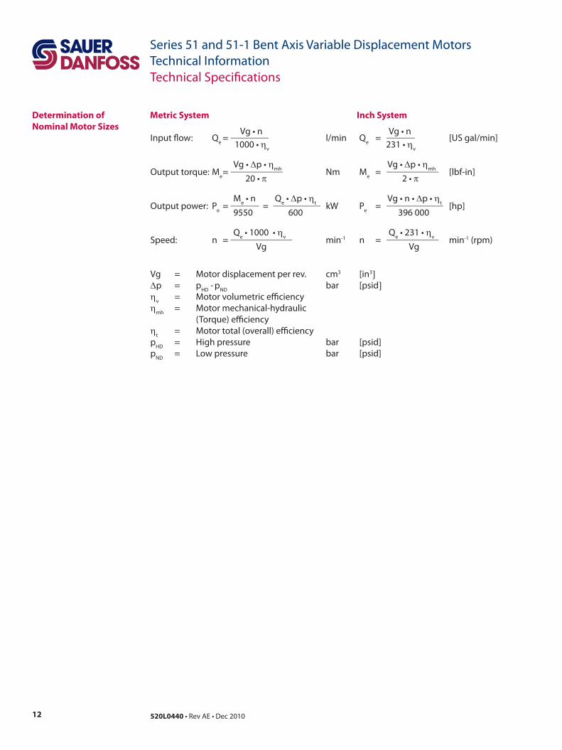
Determination ofNominal Motor Sizes Vg • n Vg • n
Input flow: Qe = ________ l/min Qe = ______ [US gal/min] 1000 • ηv 231 • ηv
Vg • ∆p • ηmh Vg • ∆p • ηmhOutput torque: Me = ___________ Nm Me = ___________ [lbf-in] 20 • π 2 • π
Me • n Qe • ∆p • ηt Vg • n • ∆p • ηtOutput power: Pe = ______ = __________ kW Pe = ____________ [hp] 9550 600 396 000
Qe • 1000 • ηv Qe • 231 • ηvSpeed: n = _____________ min-1 n = ___________ min-1 (rpm) Vg Vg
Vg = Motor displacement per rev. cm3 [in3]∆p = pHD - pND bar [psid]ηv = Motor volumetric efficiency ηmh = Motor mechanical-hydraulic (Torque) efficiencyηt = Motor total (overall) efficiencypHD = High pressure bar [psid]pND = Low pressure bar [psid]
Metric System Inch System
13520L0440 • Rev AE • Dec 2010
Series 51 and 51-1 Bent Axis Variable Displacement MotorsTechnical InformationGeneral Technical Specifications
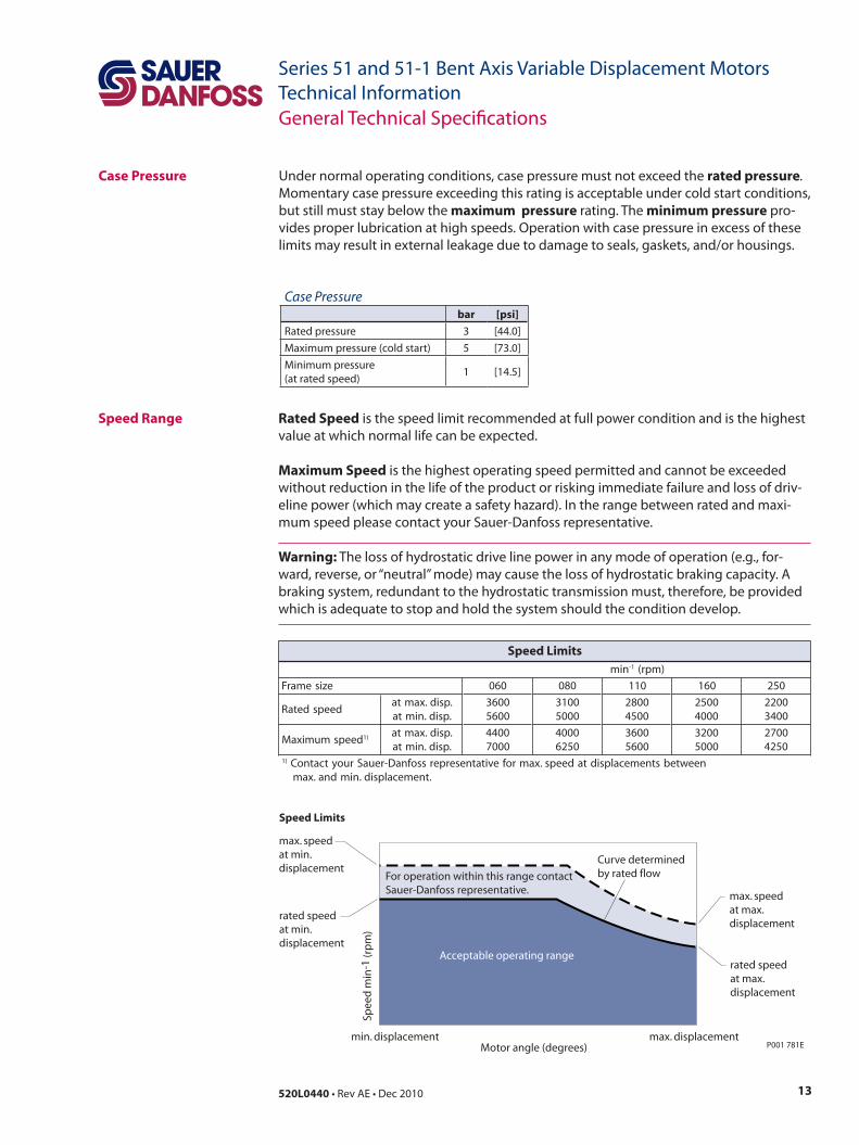
Case Pressure Under normal operating conditions, case pressure must not exceed the rated pressure. Momentary case pressure exceeding this rating is acceptable under cold start conditions, but still must stay below the maximum pressure rating. The minimum pressure pro-vides proper lubrication at high speeds. Operation with case pressure in excess of these limits may result in external leakage due to damage to seals, gaskets, and/or housings.
Speed Range Rated Speed is the speed limit recommended at full power condition and is the highest value at which normal life can be expected.
Maximum Speed is the highest operating speed permitted and cannot be exceeded without reduction in the life of the product or risking immediate failure and loss of driv-eline power (which may create a safety hazard). In the range between rated and maxi-mum speed please contact your Sauer-Danfoss representative.
Warning: The loss of hydrostatic drive line power in any mode of operation (e.g., for-ward, reverse, or “neutral” mode) may cause the loss of hydrostatic braking capacity. A braking system, redundant to the hydrostatic transmission must, therefore, be provided which is adequate to stop and hold the system should the condition develop.
rated speedat min.displacement
rated speedat max.displacement
Acceptable operating range
max. speedat min.displacement
max. speedat max.displacement
Curve determinedby rated flow
min. displacement max. displacementP001 781E
Spee
d m
in-1
(rp
m)
Motor angle (degrees)
For operation within this range contactSauer-Danfoss representative.
Speed Limits
nim 1- )mpr(
ezisemarF 060 080 011 061 052
deepsdetaR.psid.xamta.psid.nimta
00630065
00130005
00820054
00520004
00220043
deepsmumixaM )1 .psid.xamta.psid.nimta
00440007
00040526
00630065
00230005
00720524
)1 neewtebstnemecalpsidtadeeps.xamrofevitatneserperssofnaD-reuaSruoytcatnoC.tnemecalpsid.nimdna.xam
Speed Limits
Case Pressurebar [psi]
Rated pressure 3 [44.0]Maximum pressure (cold start) 5 [73.0]Minimum pressure(at rated speed) 1 [14.5]
14 520L0440 • Rev AE • Dec 2010
Series 51 and 51-1 Bent Axis Variable Displacement MotorsTechnical InformationGeneral Technical Specifications
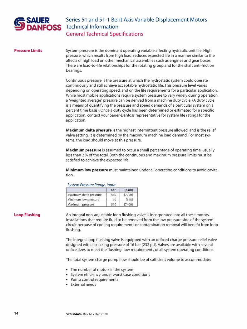
Pressure Limits System pressure is the dominant operating variable affecting hydraulic unit life. High pressure, which results from high load, reduces expected life in a manner similar to the affects of high load on other mechanical assemblies such as engines and gear boxes. There are load-to-life relationships for the rotating group and for the shaft anti-friction bearings.
Continuous pressure is the pressure at which the hydrostatic system could operate continuously and still achieve acceptable hydrostatic life. This pressure level varies depending on operating speed, and on the life requirements for a particular application. While most mobile applications require system pressure to vary widely during operation, a “weighted average” pressure can be derived from a machine duty cycle. (A duty cycle is a means of quantifying the pressure and speed demands of a particular system on a percent time basis). Once a duty cycle has been determined or estimated for a specific application, contact your Sauer-Danfoss representative for system life ratings for the application.
Maximum delta pressure is the highest intermittent pressure allowed, and is the relief valve setting. It is determined by the maximum machine load demand. For most sys-tems, the load should move at this pressure.
Maximum pressure is assumed to occur a small percentage of operating time, usually less than 2 % of the total. Both the continuous and maximum pressure limits must be satisfied to achieve the expected life.
Minimum low pressure must maintained under all operating conditions to avoid cavita-tion.
Loop Flushing An integral non-adjustable loop flushing valve is incorporated into all these motors. Installations that require fluid to be removed from the low pressure side of the system circuit because of cooling requirements or contamination removal will benefit from loop flushing.
The integral loop flushing valve is equipped with an orificed charge pressure relief valve designed with a cracking pressure of 16 bar [232 psi]. Valves are available with several orifice sizes to meet the flushing flow requirements of all system operating conditions.
The total system charge pump flow should be of sufficient volume to accommodate:
• The number of motors in the system • System efficiency under worst case conditions• Pump control requirements• External needs
System Pressure Range, Inputbar [psid]
Maximum delta pressure 480 [7000]Minimum low pressure 10 [145]Maximum pressure 510 [7400]
15520L0440 • Rev AE • Dec 2010
Series 51 and 51-1 Bent Axis Variable Displacement MotorsTechnical InformationGeneral Technical Specifications
LOOP FLUSHING SHUTTLE SPOOL
LOOP FLUSHING RELIEF VALVE
P001 782E
P001 830
BA
0 5[1.3]
10[2.6]
15[4.0]
20[5.3]
Case flow l/min [US gal/min]
Low
sys
tem
pre
ssu
re m
inu
s ca
se p
ress
ure
bar
[psi
]
25[6.6]
30[8.0]
35[9.2]
40[10.6]
[508]35
[363]25
[218]15
[73]5
P001 860E
E4 E6 F0 F3 G0 G3 H0
Loop Flushing(continued)
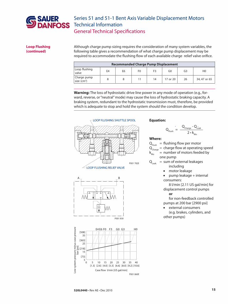
Although charge pump sizing requires the consideration of many system variables, the following table gives a recommendation of what charge pump displacement may be required to accommodate the flushing flow of each available charge relief valve orifice.
Warning: The loss of hydrostatic drive line power in any mode of operation (e.g., for-ward, reverse, or “neutral” mode) may cause the loss of hydrostatic braking capacity. A braking system, redundant to the hydrostatic transmission must, therefore, be provided which is adequate to stop and hold the system should the condition develop.
Equation: QCharge - QLeak QFlush = ____________ 2 • kMo
Where:QFlush = flushing flow per motorQCharge = charge flow at operating speedkMo = number of motors feeded by one pumpQLeak. = sum of external leakages including • motor leakage • pump leakage + internal consumers: 8 l/min [2.11 US gal/min] for displacement control pumps or for non-feedback controlled pumps at 200 bar [2900 psi] • external consumers (e.g. brakes, cylinders, and other pumps)
gnihsulfpooLevlav
4E 6E 0F 3F 0G 3G 0H
pmupegrahCmc(ezis 3)
8 8 11 41 02ro71 62 56ro74,43
Recommanded Charge Pump Displacement
16 520L0440 • Rev AE • Dec 2010
Series 51 and 51-1 Bent Axis Variable Displacement MotorsTechnical Information
All Series 51 and 51-1 motors incorporate mechanical displacement limiters. The minimum displacement of the motor is preset at the factory with a set screw in the motor housing. A tamper-proof cap is provided.
Minimum Displacement Limiter
General Technical Specifications
Hydraulic Fluids Ratings and data are based on operating with hydraulic fluids containing oxidation, rust and foam inhibitors. These fluids must possess good thermal and hydrolytic stability to prevent wear, erosion and corrosion of the internal components.
Fire resistant fluids are also suitable at modified operating conditions. Please seeSauer-Danfoss literature Hydraulic Fluids and Lubricants Technical Information for more information.
It is not permissible to mix hydraulic fluids. For more information contact yourSauer-Danfoss representative.
Suitable Hydraulic fluids:
• Hydraulic fluids per DIN 51 524, part 2 (HLP) • Hydraulic fluids per DIN 51 524, part 3 (HVLP) • API CD, CE and CF engine fluids per SAE J183• M2C33F or G automatic transmission fluids (ATF) • Agricultural multi purpose oil (STOU) • Premium turbine oils (for Premium turbine oils contact your Sauer-Danfoss representative).
Temperature and Viscosity
Temperature and viscosity requirements must be concurrently satisfied. The data shown in the tables assume petroleum-based fluids, are used.
The high temperature limits apply at the hottest point in the transmission, which is normally the motor case drain. The system should generally be run at or below the rated temperature. The maximum temperature is based on material properties and should never be exceeded.
Cold oil will generally not affect the durability of the transmission components, but it may affect the ability to flow oil and transmit power; therefore temperatures should remain 16 °C [30 °F] above the pour point of the hydraulic fluid. The minimum tempera-ture relates to the physical properties of component materials.
For maximum unit efficiency and bearing life the fluid viscosity should remain in the recommended operating range. The minimum viscosity should be encountered only during brief occasions of maximum ambient temperature and severe duty cycle opera-tion. The maximum viscosity should be encountered only at cold start.
Heat exchangers should be sized to keep the fluid within these limits. Testing to verify that these temperature limits are not exceeded is recommended.
17520L0440 • Rev AE • Dec 2010
Series 51 and 51-1 Bent Axis Variable Displacement MotorsTechnical InformationGeneral Technical Specifications
Temperature and Viscosity(continued)
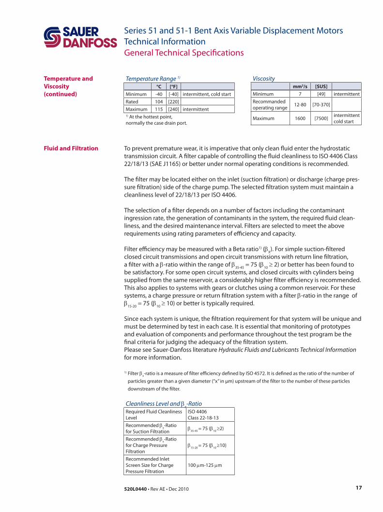
Fluid and Filtration To prevent premature wear, it is imperative that only clean fluid enter the hydrostatic transmission circuit. A filter capable of controlling the fluid cleanliness to ISO 4406 Class 22/18/13 (SAE J1165) or better under normal operating conditions is recommended.
The filter may be located either on the inlet (suction filtration) or discharge (charge pres-sure filtration) side of the charge pump. The selected filtration system must maintain a cleanliness level of 22/18/13 per ISO 4406.
The selection of a filter depends on a number of factors including the contaminant ingression rate, the generation of contaminants in the system, the required fluid clean-liness, and the desired maintenance interval. Filters are selected to meet the above requirements using rating parameters of efficiency and capacity.
Filter efficiency may be measured with a Beta ratio1) (βX). For simple suction-filtered closed circuit transmissions and open circuit transmissions with return line filtration,a filter with a β-ratio within the range of β35-45 = 75 (β10 ≥ 2) or better has been found to be satisfactory. For some open circuit systems, and closed circuits with cylinders being supplied from the same reservoir, a considerably higher filter efficiency is recommended. This also applies to systems with gears or clutches using a common reservoir. For these systems, a charge pressure or return filtration system with a filter β-ratio in the range of β15-20 = 75 (β10 ≥ 10) or better is typically required.
Since each system is unique, the filtration requirement for that system will be unique and must be determined by test in each case. It is essential that monitoring of prototypes and evaluation of components and performance throughout the test program be the final criteria for judging the adequacy of the filtration system. Please see Sauer-Danfoss literature Hydraulic Fluids and Lubricants Technical Information for more information.
1) Filter βx-ratio is a measure of filter efficiency defined by ISO 4572. It is defined as the ratio of the number of particles greater than a given diameter (“x” in µm) upstream of the filter to the number of these particles downstream of the filter.
Viscositymm2/s [SUS]
Minimum 7 [49] intermittentRecommandedoperating range 12-80 [70-370]
Maximum 1600 [7500] intermittentcold start
Temperature Range 1)
°C [°F]Minimum -40 [-40] intermittent, cold startRated 104 [220]Maximum 115 [240] intermittent1) At the hottest point,normally the case drain port.
Cleanliness Level and βx-RatioRequired Fluid Cleanliness Level
ISO 4406 Class 22-18-13
Recommended βx-Ratio for Suction Filtration β35-45 = 75 (β10 ≥2)
Recommended βx-Ratio for Charge Pressure Filtration
β15-20 = 75 (β10 ≥10)
Recommended Inlet Screen Size for Charge Pressure Filtration
100 µm-125 µm
18 520L0440 • Rev AE • Dec 2010
Series 51 and 51-1 Bent Axis Variable Displacement MotorsTechnical Information
IndependentBraking System
Warning: The loss of hydrostatic drive line power in any mode of operation (e.g., for-ward, reverse, or “neutral” mode) may cause the loss of hydrostatic braking capacity. A braking system, redundant to the hydrostatic transmission must, therefore, be provided which is adequate to stop and hold the system should the condition develop.
Reservoir The function of the reservoir is to remove air and to provide make up fluid for volume changes associated with fluid expansion or contraction, possible cylinder flow, and minor leakage.
The reservoir should be designed to accommodate maximum volume changes during all system operating modes and to promote deaeration of the fluid as it passes through the tank.
A minimum reservoir volume equal to 1/2 to 1 1/2 times charge pump flow/min is sug-gested. This allows 30 seconds fluid dwell for removing entrained air at the maximum return flow. This is usually adequate to allow for a closed reservoir (no breather) in most applications. The reservoir outlet to the charge pump inlet should be above the bottom of the reservoir to take advantage of gravity separation and prevent large foreign par-ticles from entering the charge inlet line.
The reservoir inlet (fluid return) should be positioned so that the flow to the reservoir is discharged below the normal fluid level, and also directed into the interior of the reser-voir for maximum dwell and efficient deaeration.
General Technical Specifications
19520L0440 • Rev AE • Dec 2010
Series 51 and 51-1 Bent Axis Variable Displacement MotorsTechnical InformationGeneral Technical Specifications
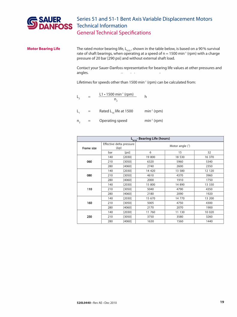
Motor Bearing Life The rated motor bearing life, Lh10 , shown in the table below, is based on a 90 % survival rate of shaft bearings, when operating at a speed of n = 1500 min-1 (rpm) with a charge pressure of 20 bar [290 psi] and without external shaft load.
Contact your Sauer-Danfoss representative for bearing life values at other pressures and angles.
Lifetimes for speeds other than 1500 min-1 (rpm) can be calculated from:
L1 • 1500 min-1 (rpm)L2 = ___________________ h n2
L1 = Rated L10 life at 1500 min-1 (rpm)
n2 = Operating speed min-1 (rpm)
ezisemarFerusserpatledevitceffE
(∆ )p)(elgnarotoM
ezisemarFrab ]isp[ 6 51 23
060
041 ]0302[ 00891 03581 07361
060 012 ]0503[ 0236 0695 0435060
082 ]0604[ 0472 0062 0532
080
041 ]0302[ 02441 08531 02121
080 012 ]0503[ 0164 0734 0693080
082 ]0604[ 0002 0191 0571
011
041 ]0302[ 00851 09841 03331
011 012 ]0503[ 0405 0974 0534011
082 ]0604[ 0812 0902 0291
061
041 ]0302[ 07651 07741 00231
061 012 ]0503[ 5005 0574 0034061
082 ]0604[ 0712 0702 0091
052
041 ]0302[ 06711 03111 02001
052 012 ]0503[ 0573 0853 0623052
082 ]0604[ 0361 0651 0441
Lh10
- Bearing Life (hours)
20 520L0440 • Rev AE • Dec 2010
Series 51 and 51-1 Bent Axis Variable Displacement MotorsTechnical InformationGeneral Technical Specifications
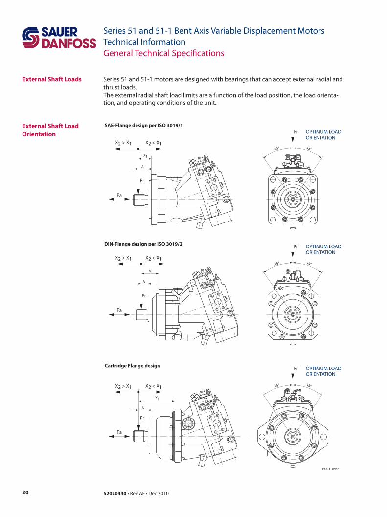
External Shaft Loads Series 51 and 51-1 motors are designed with bearings that can accept external radial and thrust loads.The external radial shaft load limits are a function of the load position, the load orienta-tion, and operating conditions of the unit.
External Shaft LoadOrientation
Fr
35° 35°
Fr
A
X1
A
A
SAE-Flange design per ISO 3019/1
DIN-Flange design per ISO 3019/2
Cartridge Flange design
35° 35°
Fa
Fa
Fa
X1
Fr
X1
X2 < X1X2 > X1
X2 < X1X2 > X1
X2 < X1X2 > X1
P001 166E
35°
Fr
Fr
Fr
35°
OPTIMUM LOADORIENTATION
OPTIMUM LOADORIENTATION
OPTIMUM LOADORIENTATION
21520L0440 • Rev AE • Dec 2010
Series 51 and 51-1 Bent Axis Variable Displacement MotorsTechnical InformationGeneral Technical Specifications
External Shaft LoadOrientation(continued)
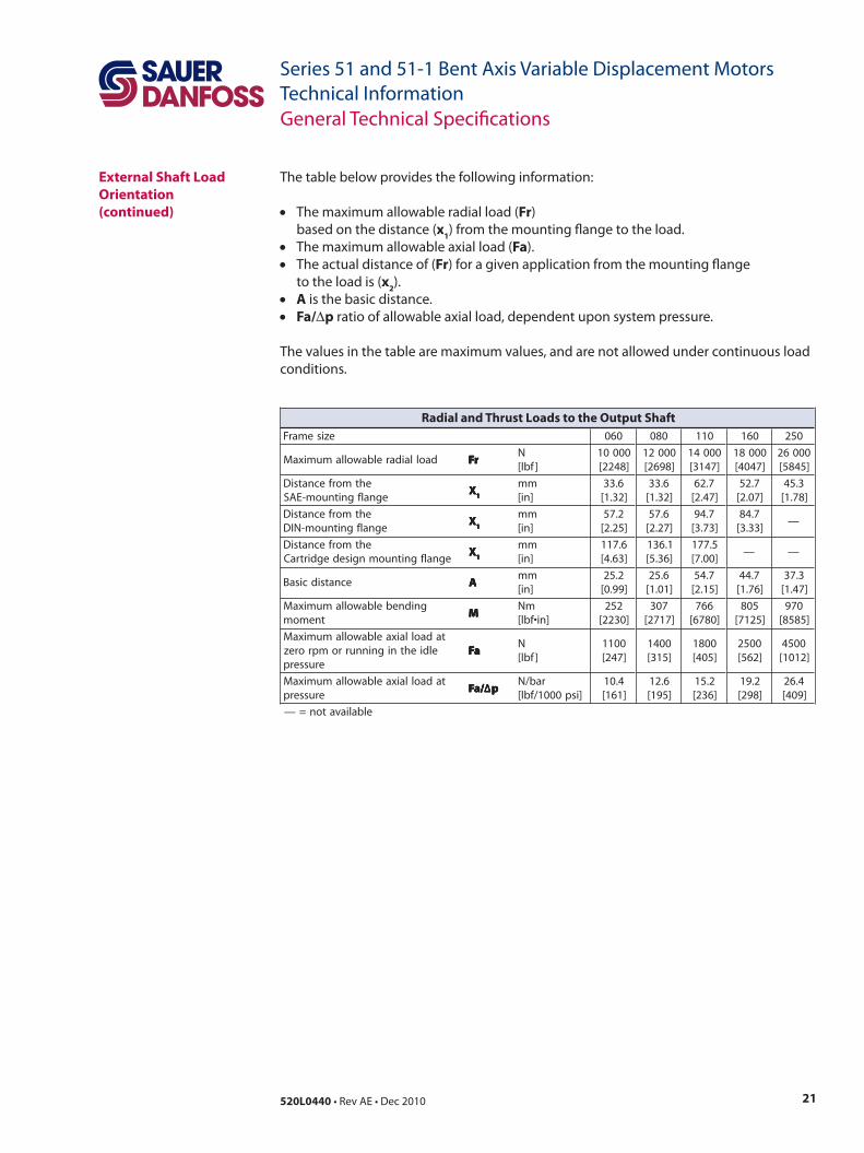
The table below provides the following information:
• The maximum allowable radial load (Fr) based on the distance (x1) from the mounting flange to the load.• The maximum allowable axial load (Fa).• The actual distance of (Fr) for a given application from the mounting flange to the load is (x2).• A is the basic distance.• Fa/∆p ratio of allowable axial load, dependent upon system pressure.
The values in the table are maximum values, and are not allowed under continuous load conditions.
ezisemarF 060 080 011 061 052
daollaidarelbawollamumixaM rFrFrFrFrFN
]fbl[00001]8422[
00021]8962[
00041]7413[
00081]7404[
00062]5485[
ehtmorfecnatsiDegnalfgnitnuom-EAS
XXXXX11111
mm]ni[
6.33]23.1[
6.33]23.1[
7.26]74.2[
7.25]70.2[
3.54]87.1[
ehtmorfecnatsiDegnalfgnitnuom-NID
XXXXX11111
mm]ni[
2.75]52.2[
6.75]72.2[
7.49]37.3[
7.48]33.3[
—
ehtmorfecnatsiDegnalfgnitnuomngisedegdirtraC
XXXXX11111
mm]ni[
6.711]36.4[
1.631]63.5[
5.771]00.7[
— —
ecnatsidcisaB AAAAAmm]ni[
2.52]99.0[
6.52]10.1[
7.45]51.2[
7.44]67.1[
3.73]74.1[
gnidnebelbawollamumixaMtnemom
MMMMMmN
]ni•fbl[252
]0322[703
]7172[667
]0876[508
]5217[079
]5858[
tadaollaixaelbawollamumixaMeldiehtnigninnurromprorez
erusserpaFaFaFaFaF
N]fbl[
0011]742[
0041]513[
0081]504[
0052]265[
0054]2101[
tadaollaixaelbawollamumixaMerusserp
/aF /aF /aF /aF /aF ∆∆∆∆∆ppppprab/N
]isp0001/fbl[4.01
]161[6.21]591[
2.51]632[
2.91]892[
4.62]904[
elbaliavaton=—
Radial and Thrust Loads to the Output Shaft
22 520L0440 • Rev AE • Dec 2010
Series 51 and 51-1 Bent Axis Variable Displacement MotorsTechnical InformationGeneral Technical Specifications
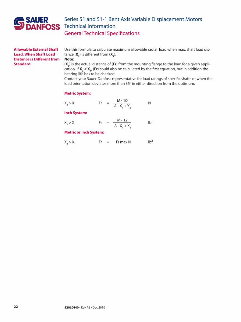
Allowable External Shaft Load, When Shaft Load Distance is Different from Standard
Use this formula to calculate maximum allowable radial load when max. shaft load dis-tance (X2) is different from (X1):Note:(X2) is the actual distance of (Fr) from the mounting flange to the load for a given appli-cation. If X2 < X1, (Fr) could also be calculated by the first equation, but in addition the bearing life has to be checked.Contact your Sauer-Danfoss representative for load ratings of specific shafts or when the load orientation deviates more than 35° in either direction from the optimum.
Metric System: M • 103
X2 > X1 Fr = _________ N A - X1 + X2
Inch System: M • 12X2 > X1 Fr = _________ lbf A - X1 + X2
Metric or Inch System:
X2 > X1 Fr = Fr max N lbf
23520L0440 • Rev AE • Dec 2010
Series 51 and 51-1 Bent Axis Variable Displacement MotorsTechnical Information
Efficiency Graphs and Maps
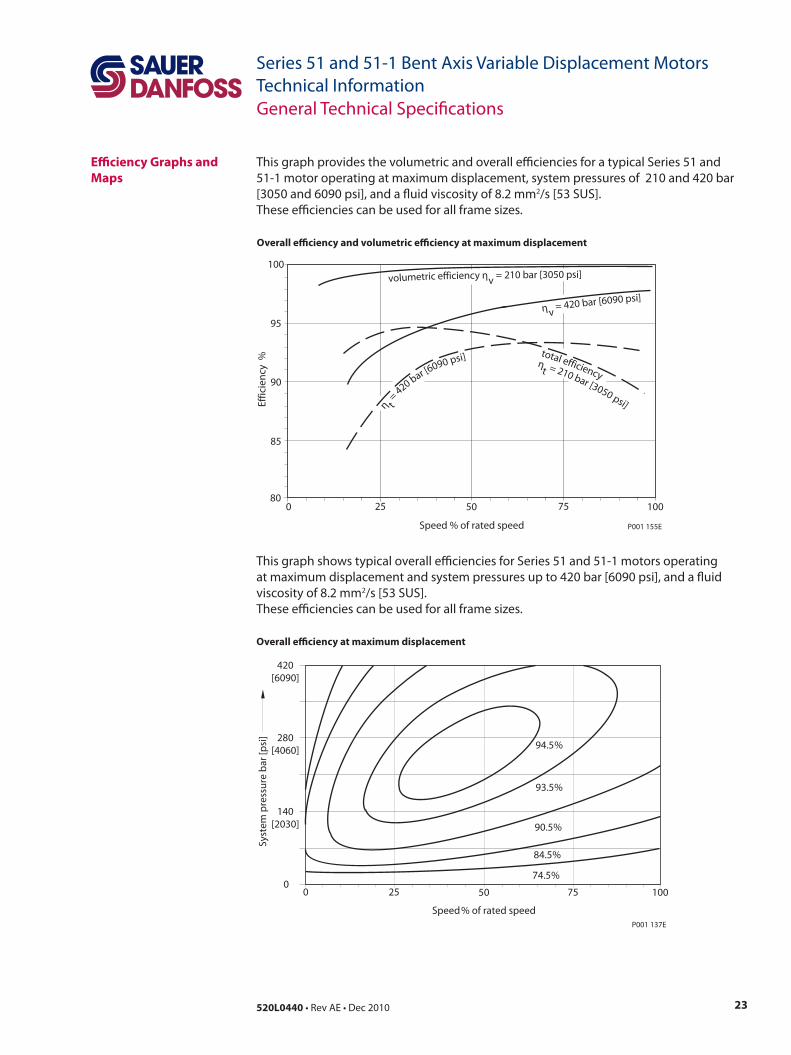
This graph provides the volumetric and overall efficiencies for a typical Series 51 and 51-1 motor operating at maximum displacement, system pressures of 210 and 420 bar [3050 and 6090 psi], and a fluid viscosity of 8.2 mm2/s [53 SUS]. These efficiencies can be used for all frame sizes.
This graph shows typical overall efficiencies for Series 51 and 51-1 motors operating at maximum displacement and system pressures up to 420 bar [6090 psi], and a fluid viscosity of 8.2 mm2/s [53 SUS].These efficiencies can be used for all frame sizes.
Overall efficiency and volumetric efficiency at maximum displacement
Effic
ien
cy %
volumetric efficiency ηv = 210 bar [3050 psi]100
95
90
85
800 25 50 75 100
Speed % of rated speed P001 155E
η t=
420 bar [6090 psi] total efficiencyηt = 210 bar [3050 psi]
η v= 420 bar [6090 psi]
Overall efficiency at maximum displacement
Speed% of rated speed
0
Syst
em p
ress
ure
bar
[psi
]
420[6090]
280[4060]
140[2030]
025 50 75 100
74.5%
84.5%
90.5%
93.5%
94.5%
P001 137E
General Technical Specifications
24 520L0440 • Rev AE • Dec 2010
Series 51 and 51-1 Bent Axis Variable Displacement MotorsTechnical Information
Efficiency Graphs and Maps(continued)
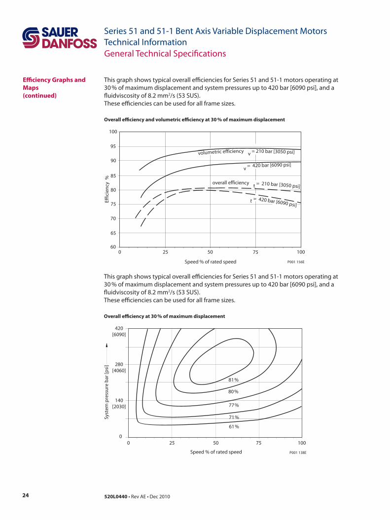
Overall efficiency and volumetric efficiency at 30 % of maximum displacement
This graph shows typical overall efficiencies for Series 51 and 51-1 motors operating at 30 % of maximum displacement and system pressures up to 420 bar [6090 psi], and a fluidviscosity of 8.2 mm2/s (53 SUS).These efficiencies can be used for all frame sizes.
This graph shows typical overall efficiencies for Series 51 and 51-1 motors operating at 30 % of maximum displacement and system pressures up to 420 bar [6090 psi], and a fluidviscosity of 8.2 mm2/s (53 SUS).These efficiencies can be used for all frame sizes.
Overall efficiency at 30 % of maximum displacement
80
v = 420 bar [6090 psi]
volumetric efficiency v = 210 bar [3050 psi]
t = 420 bar [6090 psi]
25 50 75 100060
65
70
75
85
90
95
100
Effic
ien
cy %
Speed % of rated speed
overall efficiency t = 210 bar [3050 psi]
P001 156E
Speed % of rated speed
0 1007550250
61%
71%
77%
80%
81%
Syst
em p
ress
ure
bar
[psi
]
140[2030]
280[4060]
420[6090]
P001 138E
General Technical Specifications
25520L0440 • Rev AE • Dec 2010
Series 51 and 51-1 Bent Axis Variable Displacement MotorsTechnical InformationGeneral Technical Specifications
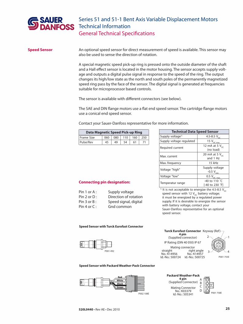
Speed Sensor An optional speed sensor for direct measurement of speed is available. This sensor may also be used to sense the direction of rotation.
A special magnetic speed pick-up ring is pressed onto the outside diameter of the shaft and a Hall effect sensor is located in the motor housing. The sensor accepts supply volt-age and outputs a digital pulse signal in response to the speed of the ring. The output changes its high/low state as the north and south poles of the permanently magnetized speed ring pass by the face of the sensor. The digital signal is generated at frequencies suitable for microprocessor based controls.
The sensor is available with different connectors (see below).
The SAE and DIN flange motors use a flat end speed sensor. The cartridge flange motors use a conical end speed sensor.
Contact your Sauer-Danfoss representative for more information.
Connecting pin designation:
Pin 1 or A : Supply voltagePin 2 or D : Direction of rotationPin 3 or B : Speed signal, digital Pin 4 or C : Gnd common
P001 492
RedWhiteBlack
Green
P002 108E
ABCD
Packard Weather-Pack4 pin
(Supplied Connector)
Mating ConnectorNo.: K03379
Id.-No.: 505341 P001 758E
Speed Sensor with Turck Eurofast Connector
Speed Sensor with Packard Weather-Pack Connector
Turck Eurofast Connector4 pin
(Supplied connector)IP Rating (DIN 40 050) IP 67
Mating connectorstraight right angleNo.: K14956 No.: K14957
Id.-No.: 500724 Id.-No.: 500725 P001 755E
12
3 4
Keyway (Ref )
eziSemarF 060 080 011 061 052
veR/esluP 54 94 45 16 17
Data Magnetic Speed Pick-up RingegatlovylppuS )1 V5.8-5.4
CD
detalugeregatlovylppuS V51.xamCD
tnerrucderiuqeRV5taAm21
CD
)daolon(
tnerruc.xaMV5taAm02
CD
zH1dna
ycneuqerf.xaM zHk51
"hgih"egatloVegatlovylppuS
V5.0-.nim
"wol"egatloV V5.0CD .xam
egnarrutarepmeTC˚011ot04-
]F032ot04-[)1 V5.8-5.4ehtezigreneotelbatpeccatonsitI
CD
V21htiwrosnesdeepsCD
;egatlovyrettabrewopdetalugeraybdezigreneebtsumti
rosnesehtezigreneotelbarisedsitifI.ylppusruoytcatnoc,egatlovyrettabhtiw
lanoitponarofevitatneserperssofnaD-reuaS.rosnesdeeps
Technical Data Speed Sensor
26 520L0440 • Rev AE • Dec 2010
Series 51 and 51-1 Bent Axis Variable Displacement MotorsTechnical InformationTypical Control and Regulator Applications
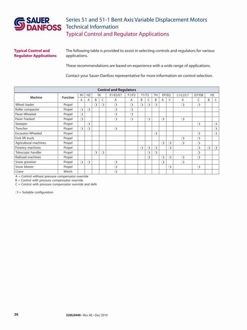
The following table is provided to assist in selecting controls and regulators for various applications.
These recommendations are based on experience with a wide range of applications.
Contact your Sauer-Danfoss representative for more information on control selection.
Typical Control and Regulator Applications
enihcaM noitcnuF1N ZH AT 7E/2E/1E 2F/1F 2T/1T HT QE/PE 7L/2L/1L 8D/7D SH
enihcaM noitcnuFA A B C A A B C B A C A C B C
redaolleehW leporP
rotcapmocrelloR leporP
deleehW-revaP leporP
dekcarT-revaP leporP
repeewS leporP
rehcnerT leporP
deleehW-rotavacxE leporP
kcurttfilkroF leporP
senihcamlarutlucirgA leporP
senihcamyrtseroF leporP
reldnahcipocseleT leporP
senihcamdaorliaR leporP
remoorgwonS leporP
rewolbwonS leporP
enarC hcniW
edirrevorotasnepmocerusserptuohtiwlortnoC=AedirrevorotasnepmocerusserphtiwlortnoC=B
efeddnaedirrevorotasnepmocerusserphtiwlortnoC=C
noitarugifnocelbatiuS=
Control and Regulators

27520L0440 • Rev AE • Dec 2010
Series 51 and 51-1 Bent Axis Variable Displacement MotorsTechnical InformationNotes
28 520L0440 • Rev AE • Dec 2010
Series 51 and 51-1 Bent Axis Variable Displacement MotorsTechnical Information
Not all control options are shown in this Technical Information. Contact your Sauer-Danfoss representative for special control functions.
HydraulicTwo-Position Control – Option
N1NN for 51-1
Frame Size060, 080, 110
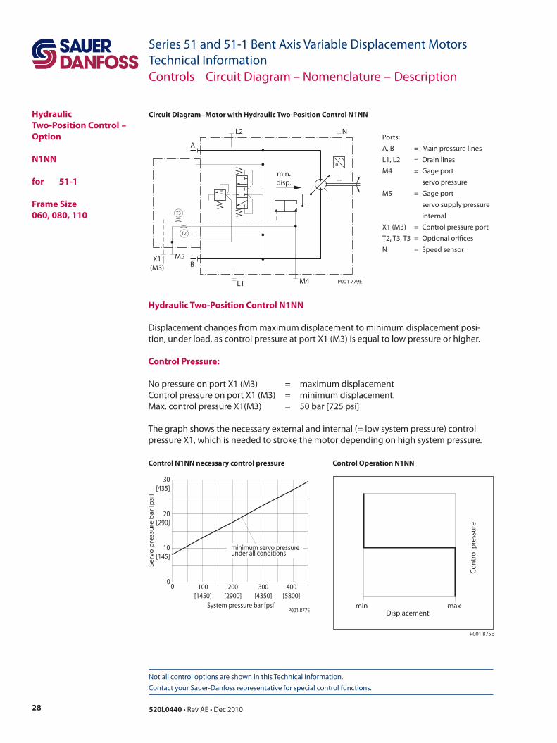
Circuit Diagram – Motor with Hydraulic Two-Position Control N1NN
X1(M3)
M5B
M4L1
NL2
A
P001 779E
n
min.disp.
T3
T2
Ports:A, B = Main pressure linesL1, L2 = Drain linesM4 = Gage port servo pressureM5 = Gage port servo supply pressure internalX1 (M3) = Control pressure portT2, T3, T3 = Optional orificesN = Speed sensor
Hydraulic Two-Position Control N1NN
Displacement changes from maximum displacement to minimum displacement posi-tion, under load, as control pressure at port X1 (M3) is equal to low pressure or higher.
Control Pressure:
No pressure on port X1 (M3) = maximum displacementControl pressure on port X1 (M3) = minimum displacement.Max. control pressure X1(M3) = 50 bar [725 psi]
The graph shows the necessary external and internal (= low system pressure) control pressure X1, which is needed to stroke the motor depending on high system pressure.
System pressure bar [psi]
Se
rvo
pre
ssu
re b
ar
[psi
]
00
200[2900]
100[1450]
10[145]
20[290]
30[435]
300[4350]
400[5800]
minimum servo pressureunder all conditions
P001 877E
P001 875E
min max
Co
ntr
ol p
ress
ure
Displacement
Control Operation N1NNControl N1NN necessary control pressure
Controls Circuit Diagram – Nomenclature – Description
29520L0440 • Rev AE • Dec 2010
Series 51 and 51-1 Bent Axis Variable Displacement MotorsTechnical Information
Not all control options are shown in this Technical Information. Contact your Sauer-Danfoss representative for special control functions.
HydraulicTwo-Position Control – Option
HZB1 for 51
Frame Size160, 250
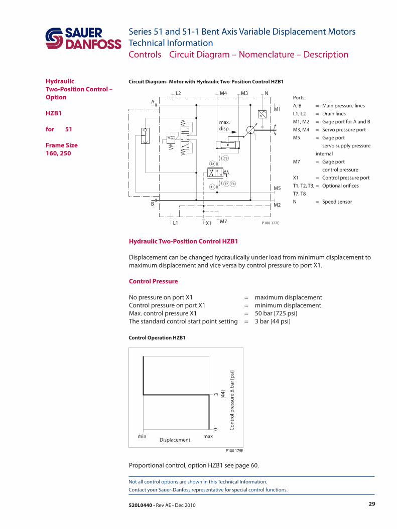
Circuit Diagram – Motor with Hydraulic Two-Position Control HZB1
Ports:A, B = Main pressure linesL1, L2 = Drain linesM1, M2 = Gage port for A and BM3, M4 = Servo pressure portM5 = Gage port servo supply pressure
internalM7 = Gage port control pressureX1 = Control pressure portT1, T2, T3, = Optional orifices T7, T8N = Speed sensor
T8
T3
T7T1
T2
max.disp.
M2
X1 M7
B
M5
L1
M1
M4L2
A
M3 N
P100 177E
n
Hydraulic Two-Position Control HZB1
Displacement can be changed hydraulically under load from minimum displacement to maximum displacement and vice versa by control pressure to port X1.
Control Pressure
No pressure on port X1 = maximum displacementControl pressure on port X1 = minimum displacement.Max. control pressure X1 = 50 bar [725 psi] The standard control start point setting = 3 bar [44 psi]
P100 179E
Co
ntr
ol p
ress
ure
∆ b
ar [p
si]
03 [44]
min maxDisplacement
Control Operation HZB1
Controls Circuit Diagram – Nomenclature – Description
Proportional control, option HZB1 see page 60.
30 520L0440 • Rev AE • Dec 2010
Series 51 and 51-1 Bent Axis Variable Displacement MotorsTechnical Information
Not all control options are shown in this Technical Information. Contact your Sauer-Danfoss representative for special control functions.
Pressure Compensator Control – Options
TA**
for 51-1
Frame Size060, 080, 110
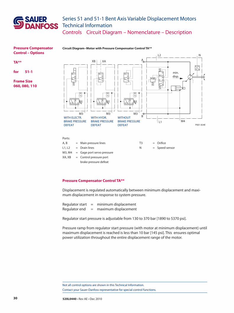
Circuit Diagram – Motor with Pressure Compensator Control TA**
Ports:A, B = Main pressure lines T3 = OrificeL1, L2 = Drain lines N = Speed sensorM3, M4 = Gage port servo pressure XA, XB = Control pressure port brake pressure defeat
Pressure Compensator Control TA**
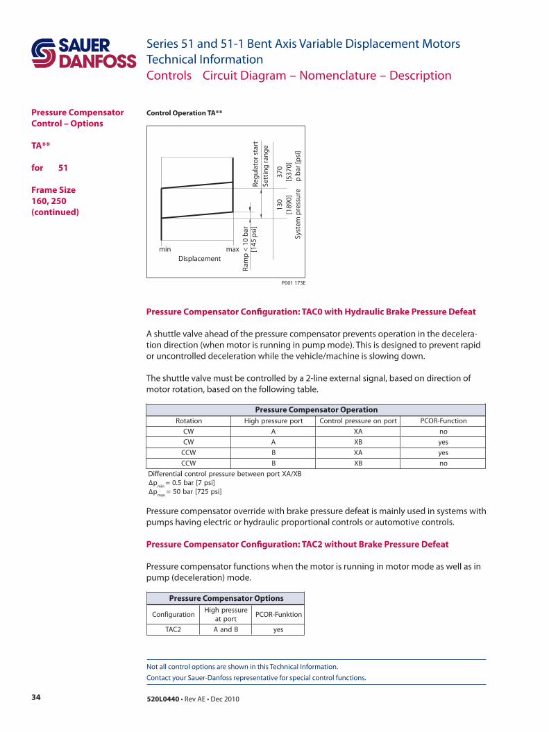
Displacement is regulated automatically between minimum displacement and maxi-mum displacement in response to system pressure.
Regulator start = minimum displacementRegulator end = maximum displacement
Regulator start pressure is adjustable from 130 to 370 bar [1890 to 5370 psi].
Pressure ramp from regulator start pressure (with motor at minimum displacement) until maximum displacement is reached is less than 10 bar [145 psi]. This ensures optimal power utilization throughout the entire displacement range of the motor.
Controls Circuit Diagram – Nomenclature – Description
M3
T3
M3WITH HYDR.BRAKE PRESSUREDEFEAT
WITH ELECTR.BRAKE PRESSUREDEFEAT
WITHOUTBRAKE PRESSUREDEFEAT
XB XA
T3
M3
T3
min.disp.
n
B
A
L1 M4
L2 N
P001 834E
31520L0440 • Rev AE • Dec 2010
Series 51 and 51-1 Bent Axis Variable Displacement MotorsTechnical Information
Not all control options are shown in this Technical Information. Contact your Sauer-Danfoss representative for special control functions.
Pressure Compensator Control – Options
TA** for 51-1
Frame Size060, 080, 110(continued)
min maxDisplacement
Ram
p <
10 b
ar[1
45 p
si]
Regu
lato
r sta
rtSe
ttin
g ra
nge
130
[189
0]37
0[5
370]
Syst
em p
ress
ure
p b
ar [p
si]
P001 173E
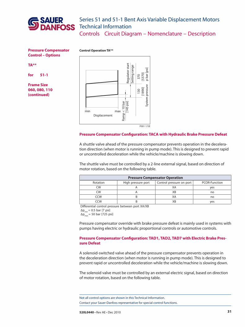
Pressure Compensator Configuration: TACA with Hydraulic Brake Pressure Defeat
A shuttle valve ahead of the pressure compensator prevents operation in the decelera-tion direction (when motor is running in pump mode). This is designed to prevent rapid or uncontrolled deceleration while the vehicle/machine is slowing down.
The shuttle valve must be controlled by a 2-line external signal, based on direction of motor rotation, based on the following table.
Pressure compensator override with brake pressure defeat is mainly used in systems with pumps having electric or hydraulic proportional controls or automotive controls.
Pressure Compensator Configuration: TAD1, TAD2, TAD7 with Electric Brake Pres-sure Defeat
A solenoid-switched valve ahead of the pressure compensator prevents operation in the deceleration direction (when motor is running in pump mode). This is designed to prevent rapid or uncontrolled deceleration while the vehicle/machine is slowing down.
The solenoid valve must be controlled by an external electric signal, based on direction of motor rotation, based on the following table.
Control Operation TA**
Controls Circuit Diagram – Nomenclature – Description
noitatoR troperusserphgiH tropnoerusserplortnoC noitcnuF-ROCP
WC A AX sey
WC A BX on
WCC B AX on
WCC B BX sey
BX/AXtropneewteberusserplortnoclaitnereffiD∆p
nim]isp7[rab5.0=
∆pxam
]isp527[rab05=
Pressure Compensator Operation
32 520L0440 • Rev AE • Dec 2010
Series 51 and 51-1 Bent Axis Variable Displacement MotorsTechnical Information
Not all control options are shown in this Technical Information. Contact your Sauer-Danfoss representative for special control functions.
Pressure Compensator Control – Options
TA**
for 51-1
Frame Size060, 080, 110(continued)
Controls Circuit Diagram – Nomenclature – Description
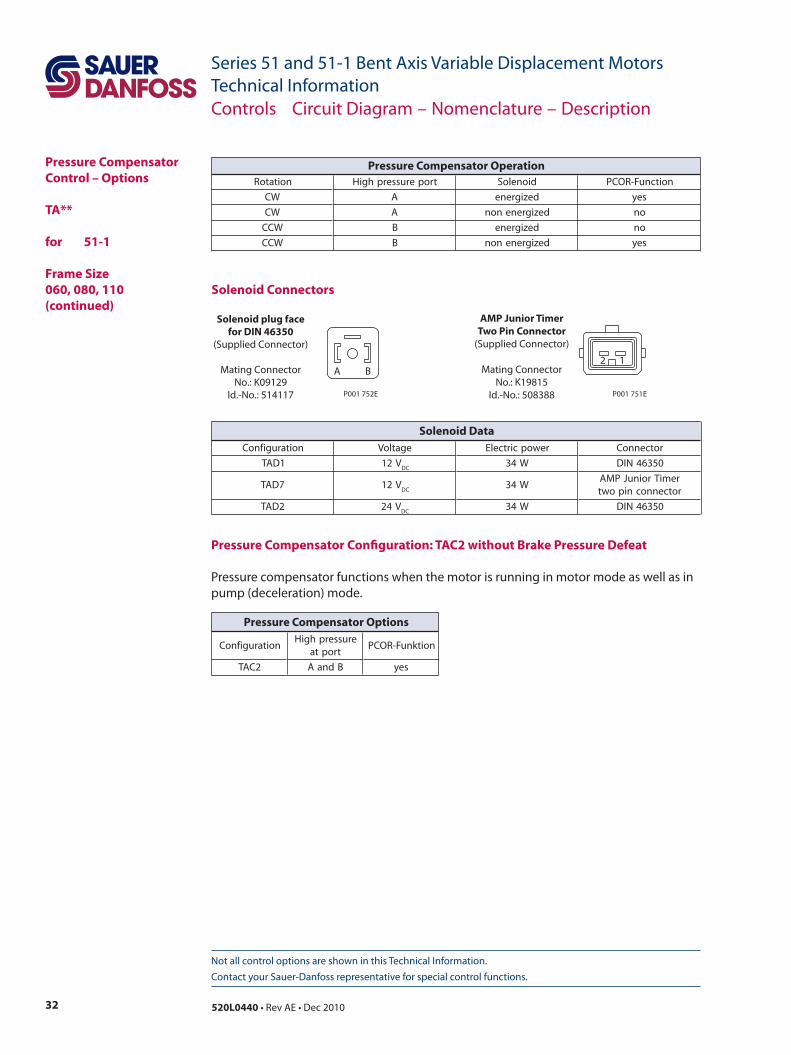
Pressure Compensator Configuration: TAC2 without Brake Pressure Defeat
Pressure compensator functions when the motor is running in motor mode as well as in pump (deceleration) mode.
noitatoR troperusserphgiH dioneloS noitcnuF-ROCP
WC A dezigrene sey
WC A dezigrenenon on
WCC B dezigrene on
WCC B dezigrenenon sey
Pressure Compensator Operation
noitarugifnoCerusserphgiH
troptanoitknuF-ROCP
2CAT BdnaA sey
Pressure Compensator Options
Solenoid Connectors
Solenoid plug facefor DIN 46350
(Supplied Connector)
Mating ConnectorNo.: K09129
Id.-No.: 514117
A B
P001 752E
AMP Junior TimerTwo Pin Connector
(Supplied Connector)
Mating ConnectorNo.: K19815
Id.-No.: 508388
2 1
P001 751E
noitarugifnoC egatloV rewopcirtcelE rotcennoC
1DAT V21CD
W43 05364NID
7DAT V21CD
W43remiTroinuJPMArotcennocnipowt
2DAT V42CD
W43 05364NID
Solenoid Data
33520L0440 • Rev AE • Dec 2010
Series 51 and 51-1 Bent Axis Variable Displacement MotorsTechnical Information
Not all control options are shown in this Technical Information. Contact your Sauer-Danfoss representative for special control functions.
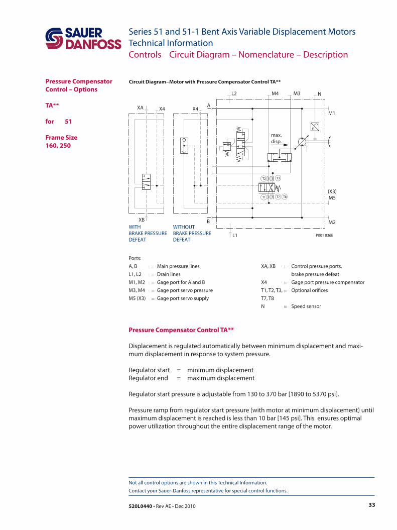
Circuit Diagram – Motor with Pressure Compensator Control TA** Pressure Compensator Control – Options
TA** for 51
Frame Size160, 250
Ports:A, B = Main pressure lines XA, XB = Control pressure ports,L1, L2 = Drain lines brake pressure defeatM1, M2 = Gage port for A and B X4 = Gage port pressure compensatorM3, M4 = Gage port servo pressure T1, T2, T3, = Optional orifices M5 (X3) = Gage port servo supply T7, T8 N = Speed sensor
Pressure Compensator Control TA**
Displacement is regulated automatically between minimum displacement and maxi-mum displacement in response to system pressure.
Regulator start = minimum displacementRegulator end = maximum displacement
Regulator start pressure is adjustable from 130 to 370 bar [1890 to 5370 psi].
Pressure ramp from regulator start pressure (with motor at minimum displacement) until maximum displacement is reached is less than 10 bar [145 psi]. This ensures optimal power utilization throughout the entire displacement range of the motor.
Controls Circuit Diagram – Nomenclature – Description
n
max.disp.
T7 T8
T2
T1
T3
B M2
(X3)M5
L1
WITHBRAKE PRESSUREDEFEAT
WITHOUTBRAKE PRESSUREDEFEAT
M1
NM3M4L2
A
P001 836E
XB
XA X4 X4
34 520L0440 • Rev AE • Dec 2010
Series 51 and 51-1 Bent Axis Variable Displacement MotorsTechnical Information
Not all control options are shown in this Technical Information. Contact your Sauer-Danfoss representative for special control functions.
Pressure Compensator Control – Options
TA** for 51
Frame Size160, 250(continued)
Pressure Compensator Configuration: TAC0 with Hydraulic Brake Pressure Defeat
A shuttle valve ahead of the pressure compensator prevents operation in the decelera-tion direction (when motor is running in pump mode). This is designed to prevent rapid or uncontrolled deceleration while the vehicle/machine is slowing down.
The shuttle valve must be controlled by a 2-line external signal, based on direction of motor rotation, based on the following table.
Pressure compensator override with brake pressure defeat is mainly used in systems with pumps having electric or hydraulic proportional controls or automotive controls.
Pressure Compensator Configuration: TAC2 without Brake Pressure Defeat
Pressure compensator functions when the motor is running in motor mode as well as in pump (deceleration) mode.
Controls Circuit Diagram – Nomenclature – Description
noitarugifnoCerusserphgiH
troptanoitknuF-ROCP
2CAT BdnaA sey
Pressure Compensator Options
min maxDisplacement
Ram
p <
10 b
ar[1
45 p
si]
Regu
lato
r sta
rtSe
ttin
g ra
nge
130
[189
0]37
0[5
370]
Syst
em p
ress
ure
p b
ar [p
si]
P001 173E
Control Operation TA**
noitatoR troperusserphgiH tropnoerusserplortnoC noitcnuF-ROCP
WC A AX on
WC A BX sey
WCC B AX sey
WCC B BX on
BX/AXtropneewteberusserplortnoclaitnereffiD∆p
nim]isp7[rab5.0=
∆pxam
]isp527[rab05=
Pressure Compensator Operation
35520L0440 • Rev AE • Dec 2010
Series 51 and 51-1 Bent Axis Variable Displacement MotorsTechnical Information
Not all control options are shown in this Technical Information. Contact your Sauer-Danfoss representative for special control functions.
HydraulicTwo-Position Control – Options
TH** for 51-1
Frame Size060, 080, 110
Circuit Diagram – Motor with Two-Position Control TH**
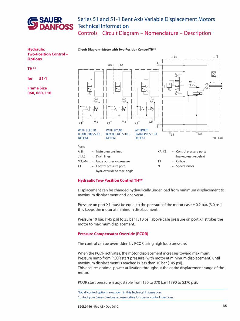
Hydraulic Two-Position Control TH**
Displacement can be changed hydraulically under load from minimum displacement to maximum displacement and vice versa.
Pressure on port X1 must be equal to the pressure of the motor case ± 0.2 bar, [3.0 psi] this keeps the motor at minimum displacement.
Pressure 10 bar, [145 psi] to 35 bar, [510 psi] above case pressure on port X1 strokes the motor to maximum displacement.
Pressure Compensator Override (PCOR)
The control can be overridden by PCOR using high loop pressure.
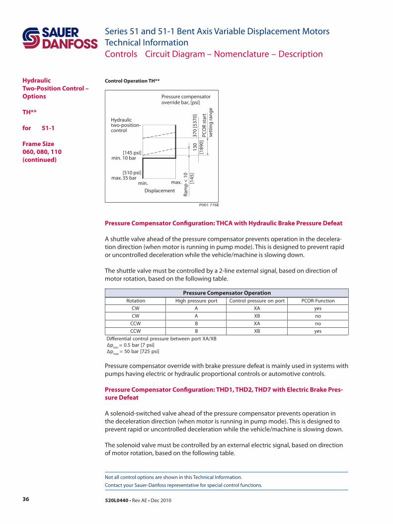
When the PCOR activates, the motor displacement increases toward maximum.Pressure ramp from PCOR start pressure (with motor at minimum displacement) until maximum displacement is reached is less than 10 bar [145 psi]. This ensures optimal power utilization throughout the entire displacement range of the motor.
PCOR start pressure is adjustable from 130 to 370 bar [1890 to 5370 psi].
Ports:A, B = Main pressure lines XA, XB = Control pressure portsL1, L2 = Drain lines brake pressure defeatM3, M4 = Gage port servo pressure T3 = OrificeX1 = Control pressure port, N = Speed sensor hydr. override to max. angle
Controls Circuit Diagram – Nomenclature – Description
n
min.disp.
B
M4L1
NL2
A
P001 835E
T3
M3X1
WITH HYDR.BRAKE PRESSUREDEFEAT
WITHOUTBRAKE PRESSUREDEFEAT
T3
M3
XB XA
X1
WITH ELECTR.BRAKE PRESSUREDEFEAT
T3
M3X1
36 520L0440 • Rev AE • Dec 2010
Series 51 and 51-1 Bent Axis Variable Displacement MotorsTechnical Information
Not all control options are shown in this Technical Information. Contact your Sauer-Danfoss representative for special control functions.
Pressure Compensator Configuration: THCA with Hydraulic Brake Pressure Defeat
A shuttle valve ahead of the pressure compensator prevents operation in the decelera-tion direction (when motor is running in pump mode). This is designed to prevent rapid or uncontrolled deceleration while the vehicle/machine is slowing down.
The shuttle valve must be controlled by a 2-line external signal, based on direction of motor rotation, based on the following table.
Pressure compensator override with brake pressure defeat is mainly used in systems with pumps having electric or hydraulic proportional controls or automotive controls.
Pressure Compensator Configuration: THD1, THD2, THD7 with Electric Brake Pres-sure Defeat
A solenoid-switched valve ahead of the pressure compensator prevents operation in the deceleration direction (when motor is running in pump mode). This is designed to prevent rapid or uncontrolled deceleration while the vehicle/machine is slowing down.
The solenoid valve must be controlled by an external electric signal, based on direction of motor rotation, based on the following table.
Controls Circuit Diagram – Nomenclature – Description
HydraulicTwo-Position Control – Options
TH**
for 51-1
Frame Size 060, 080, 110(continued)
min.
[145 psi]min. 10 bar
[510 psi] max. 35 bar
max.
Displacement
Hydraulictwo-position-control
PCO
R st
art
sett
ing
ran
ge
Ram
p <
10
[145
]13
0[1
890]
370
[537
0]
Pressure compensatoroverride bar, [psi]
P001 776E
Control Operation TH**
noitatoR troperusserphgiH tropnoerusserplortnoC noitcnuF-ROCP
WC A AX sey
WC A BX on
WCC B AX on
WCC B BX sey
BX/AXtropneewteberusserplortnoclaitnereffiD∆p
nim]isp7[rab5.0=
∆pxam
]isp527[rab05=
Pressure Compensator Operation
37520L0440 • Rev AE • Dec 2010
Series 51 and 51-1 Bent Axis Variable Displacement MotorsTechnical Information
Not all control options are shown in this Technical Information. Contact your Sauer-Danfoss representative for special control functions.
Controls Circuit Diagram – Nomenclature – Description
HydraulicTwo-Position Control – Options
TH**
for 51-1
Frame Size 060, 080, 110(continued)
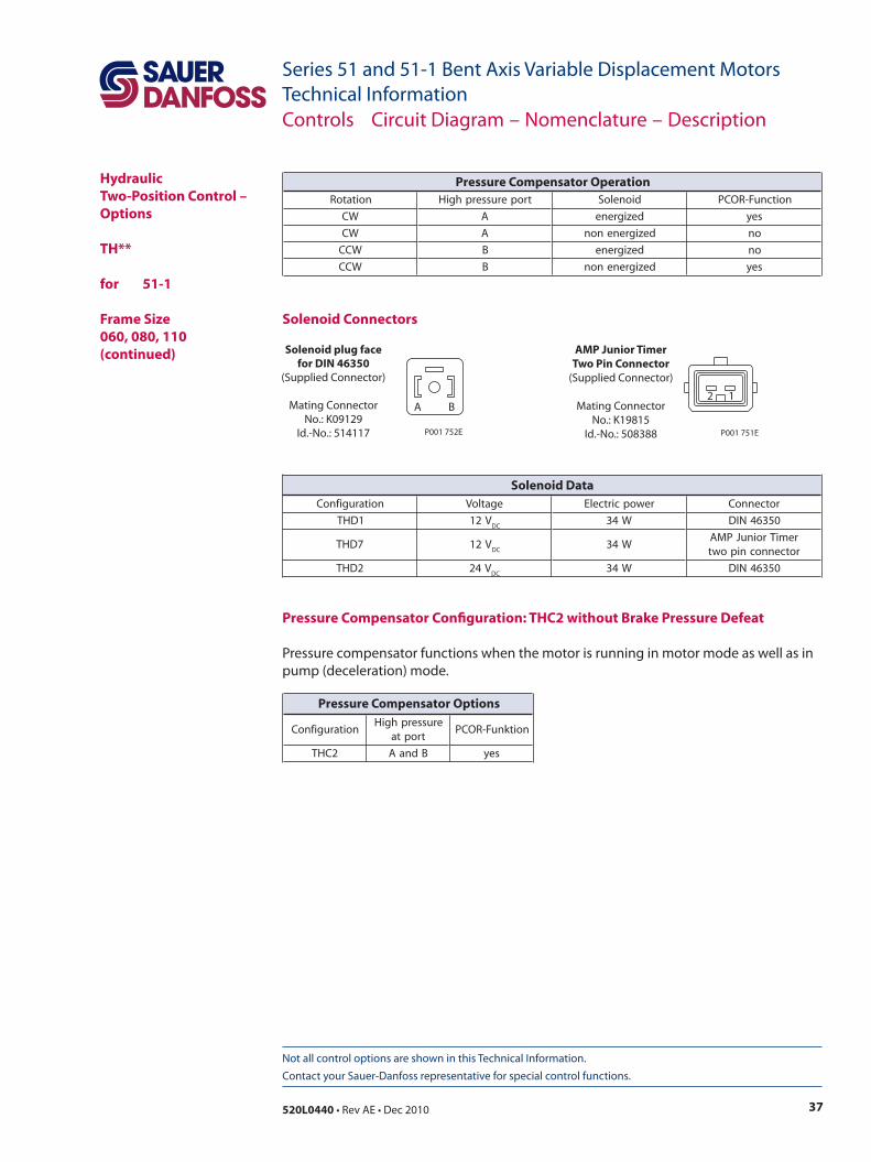
Pressure Compensator Configuration: THC2 without Brake Pressure Defeat
Pressure compensator functions when the motor is running in motor mode as well as in pump (deceleration) mode.
noitatoR troperusserphgiH dioneloS noitcnuF-ROCP
WC A dezigrene sey
WC A dezigrenenon on
WCC B dezigrene on
WCC B dezigrenenon sey
Pressure Compensator Operation
noitarugifnoCerusserphgiH
troptanoitknuF-ROCP
2CHT BdnaA sey
Pressure Compensator Options
Solenoid Connectors
Solenoid plug facefor DIN 46350
(Supplied Connector)
Mating ConnectorNo.: K09129
Id.-No.: 514117
A B
P001 752E
AMP Junior TimerTwo Pin Connector
(Supplied Connector)
Mating ConnectorNo.: K19815
Id.-No.: 508388
2 1
P001 751E
noitarugifnoC egatloV rewopcirtcelE rotcennoC
1DHT V21CD
W43 05364NID
7DHT V21CD
W43remiTroinuJPMArotcennocnipowt
2DHT V42CD
W43 05364NID
Solenoid Data
38 520L0440 • Rev AE • Dec 2010
Series 51 and 51-1 Bent Axis Variable Displacement MotorsTechnical Information
Not all control options are shown in this Technical Information. Contact your Sauer-Danfoss representative for special control functions.
HydraulicTwo-Position Control – Options
TH** for 51
Frame Size 160, 250
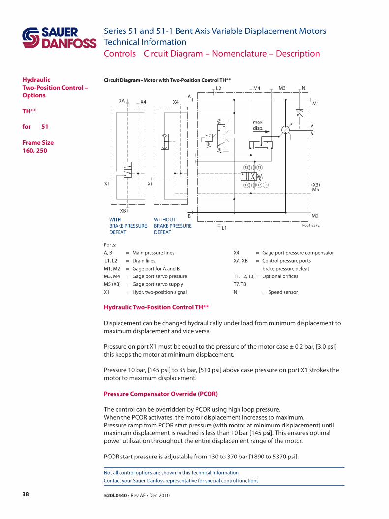
Circuit Diagram – Motor with Two-Position Control TH**
Hydraulic Two-Position Control TH**
Displacement can be changed hydraulically under load from minimum displacement to maximum displacement and vice versa.
Pressure on port X1 must be equal to the pressure of the motor case ± 0.2 bar, [3.0 psi] this keeps the motor at minimum displacement.
Pressure 10 bar, [145 psi] to 35 bar, [510 psi] above case pressure on port X1 strokes the motor to maximum displacement.
Pressure Compensator Override (PCOR)
The control can be overridden by PCOR using high loop pressure.When the PCOR activates, the motor displacement increases to maximum.Pressure ramp from PCOR start pressure (with motor at minimum displacement) until maximum displacement is reached is less than 10 bar [145 psi]. This ensures optimal power utilization throughout the entire displacement range of the motor.
PCOR start pressure is adjustable from 130 to 370 bar [1890 to 5370 psi].
Ports:A, B = Main pressure lines X4 = Gage port pressure compensator L1, L2 = Drain lines XA, XB = Control pressure ports M1, M2 = Gage port for A and B brake pressure defeatM3, M4 = Gage port servo pressure T1, T2, T3, = Optional orificesM5 (X3) = Gage port servo supply T7, T8X1 = Hydr. two-position signal N = Speed sensor
Controls Circuit Diagram – Nomenclature – Description
max.disp.
A
L2 M4 M3 N
M1
L1
X1X1
M2BWITHBRAKE PRESSUREDEFEAT
WITHOUTBRAKE PRESSUREDEFEAT
(X3)M5
P001 837E
n
T8T1
T2 T3
T7
XB
XA X4 X4
39520L0440 • Rev AE • Dec 2010
Series 51 and 51-1 Bent Axis Variable Displacement MotorsTechnical Information
Not all control options are shown in this Technical Information. Contact your Sauer-Danfoss representative for special control functions.
min.
[145 psi]min. 10 bar
[510 psi] max. 35 bar
max.
Displacement
Hydraulictwo-position-control
PCO
R st
art
sett
ing
ran
ge
Ram
p <
10
[145
]13
0[1
890]
370
[537
0]
Pressure compensatoroverride bar, [psi]
P001 776E
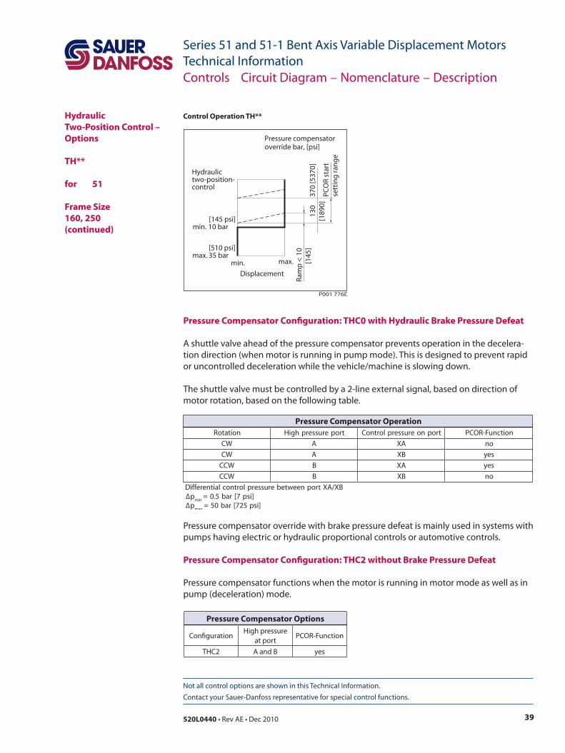
Control Operation TH**
Pressure Compensator Configuration: THC0 with Hydraulic Brake Pressure Defeat
A shuttle valve ahead of the pressure compensator prevents operation in the decelera-tion direction (when motor is running in pump mode). This is designed to prevent rapid or uncontrolled deceleration while the vehicle/machine is slowing down.
The shuttle valve must be controlled by a 2-line external signal, based on direction of motor rotation, based on the following table.
Pressure compensator override with brake pressure defeat is mainly used in systems with pumps having electric or hydraulic proportional controls or automotive controls.
Pressure Compensator Configuration: THC2 without Brake Pressure Defeat
Pressure compensator functions when the motor is running in motor mode as well as in pump (deceleration) mode.
Controls Circuit Diagram – Nomenclature – Description
HydraulicTwo-Position Control – Options
TH** for 51
Frame Size 160, 250(continued)
noitatoR troperusserphgiH tropnoerusserplortnoC noitcnuF-ROCP
WC A AX on
WC A BX sey
WCC B AX sey
WCC B BX on
BX/AXtropneewteberusserplortnoclaitnereffiD∆p
nim]isp7[rab5.0=
∆pxam
]isp527[rab05=
Pressure Compensator Operation
Pressure Compensator Options
ConfigurationHigh pressure
at portPCOR-Function
THC2 A and B yes
40 520L0440 • Rev AE • Dec 2010
Series 51 and 51-1 Bent Axis Variable Displacement MotorsTechnical Information
Not all control options are shown in this Technical Information. Contact your Sauer-Danfoss representative for special control functions.
Electrohydraulic Two-Position Control – Options
E1B1, E2B1, E7B1 for 51-1
Frame Size 060, 080, 110
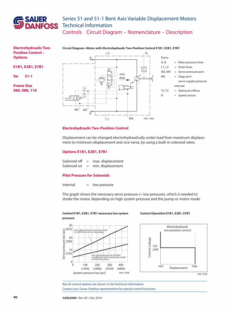
Circuit Diagram – Motor with Electrohydraulic Two-Position Control E1B1, E2B1, E7B1
Electrohydraulic Two-Position Control
Displacement can be changed electrohydraulically under load from maximum displace-ment to minimum displacement and vice versa, by using a built-in solenoid valve.
Options E1B1, E2B1, E7B1
Solenoid off = max. displacementSolenoid on = min. displacement
Pilot Pressure for Solenoid:
internal = low pressure
The graph shows the necessary servo pressure (= low pressure), which is needed to stroke the motor, depending on high system pressure and the pump or motor mode.
System pressure bar [psi]
Serv
o p
ress
ure
bar
[psi
]
00
200[2900]
100[1450]
10[145]
20[290]
30[435]
300[4350]
400[5800]
min. pilot pressure in pump modeto shift from min to max angle
min. pilot pressure at all otherconditions motor and pump modein both directions
P001 878E
min
12V/24V
max Displacement
Co
ntr
ol v
olt
age
P001 870E
Electrohydraulictwo-position control
Control Operation E1B1, E2B1, E7B1 Control E1B1, E2B1, E7B1 necessary low system pressure
Ports:A, B = Main pressure linesL1, L2 = Drain linesM3, M4 = Servo pressure portM5 = Gage port servo supply pressure
internalT2, T3 = Optional orificesN = Speed sensor
Controls Circuit Diagram – Nomenclature – Description
n
min.disp.
T3
T2
M4
BM3M5
L1
NL2
A
P001 780E
41520L0440 • Rev AE • Dec 2010
Series 51 and 51-1 Bent Axis Variable Displacement MotorsTechnical Information
Not all control options are shown in this Technical Information. Contact your Sauer-Danfoss representative for special control functions.
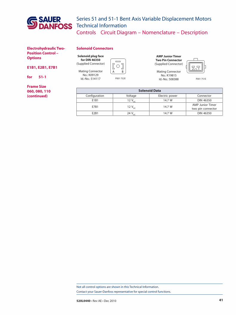
Solenoid Connectors
Solenoid plug facefor DIN 46350
(Supplied Connector)
Mating ConnectorNo.: K09129
Id.-No.: 514117
A B
P001 752E
AMP Junior TimerTwo Pin Connector
(Supplied Connector)
Mating ConnectorNo.: K19815
Id.-No.: 508388
2 1
P001 751E
Controls Circuit Diagram – Nomenclature – Description
Electrohydraulic Two-Position Control – Options
E1B1, E2B1, E7B1 for 51-1
Frame Size 060, 080, 110(continued) noitarugifnoC egatloV rewopcirtcelE rotcennoC
1B1E V21CD
W7.41 05364NID
1B7E V21CD
W7.41remiTroinuJPMArotcennocnipowt
1B2E V42CD
W7.41 05364NID
Solenoid Data
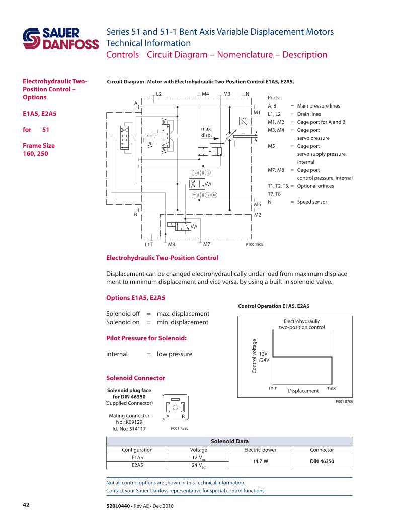
42 520L0440 • Rev AE • Dec 2010
Series 51 and 51-1 Bent Axis Variable Displacement MotorsTechnical Information
Not all control options are shown in this Technical Information. Contact your Sauer-Danfoss representative for special control functions.
Electrohydraulic Two-Position Control – Options
E1A5, E2A5 for 51
Frame Size 160, 250
Circuit Diagram – Motor with Electrohydraulic Two-Position Control E1A5, E2A5,
n
max.disp.
T3T2
T1 T7 T8
P100 180E
B
M8 M7
M2
L1
M1
NM3M4L2
A
M5
Ports:A, B = Main pressure linesL1, L2 = Drain linesM1, M2 = Gage port for A and BM3, M4 = Gage port servo pressureM5 = Gage port servo supply pressure, internalM7, M8 = Gage port control pressure, internalT1, T2, T3, = Optional orifices T7, T8N = Speed sensor
Electrohydraulic Two-Position Control
Displacement can be changed electrohydraulically under load from maximum displace-ment to minimum displacement and vice versa, by using a built-in solenoid valve.
Options E1A5, E2A5
Solenoid off = max. displacementSolenoid on = min. displacement
Pilot Pressure for Solenoid:
internal = low pressure
Solenoid Connectormin
12V/24V
max Displacement
Co
ntr
ol v
olt
age
P001 870E
Electrohydraulictwo-position control
Solenoid plug facefor DIN 46350
(Supplied Connector)
Mating ConnectorNo.: K09129
Id.-No.: 514117
A B
P001 752E
Controls Circuit Diagram – Nomenclature – Description
Control Operation E1A5, E2A5
noitarugifnoC egatloV rewopcirtcelE rotcennoC
5A1E V21CD W7.41 05364NID
5A2E V42CD
W7.41 05364NID
Solenoid Data
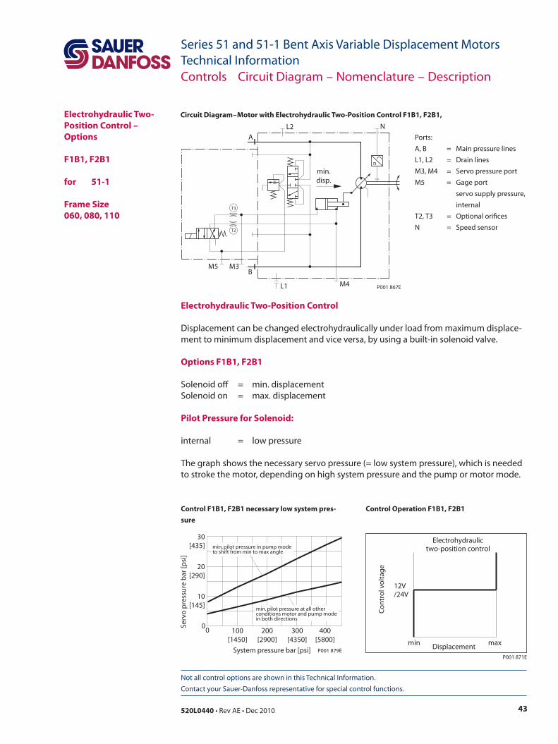
43520L0440 • Rev AE • Dec 2010
Series 51 and 51-1 Bent Axis Variable Displacement MotorsTechnical Information
Not all control options are shown in this Technical Information. Contact your Sauer-Danfoss representative for special control functions.
Electrohydraulic Two-Position Control – Options
F1B1, F2B1 for 51-1
Frame Size060, 080, 110
Circuit Diagram – Motor with Electrohydraulic Two-Position Control F1B1, F2B1,
n
min.disp.
T3
T2
M4
BM3M5
L1
NL2
A
P001 867E
Electrohydraulic Two-Position Control
Displacement can be changed electrohydraulically under load from maximum displace-ment to minimum displacement and vice versa, by using a built-in solenoid valve.
Options F1B1, F2B1
Solenoid off = min. displacementSolenoid on = max. displacement
Pilot Pressure for Solenoid:
internal = low pressure
The graph shows the necessary servo pressure (= low system pressure), which is needed to stroke the motor, depending on high system pressure and the pump or motor mode.
min
12V/24V
maxDisplacement
Co
ntr
ol v
olt
age
Electrohydraulictwo-position control
P001 871E
Control Operation F1B1, F2B1
System pressure bar [psi]
Serv
o p
ress
ure
bar
[psi
]
00
200[2900]
100[1450]
10[145]
20[290]
30[435]
300[4350]
400[5800]
min. pilot pressure in pump modeto shift from min to max angle
min. pilot pressure at all otherconditions motor and pump modein both directions
P001 879E
Control F1B1, F2B1 necessary low system pres-sure
Ports:A, B = Main pressure linesL1, L2 = Drain linesM3, M4 = Servo pressure portM5 = Gage port servo supply pressure, internalT2, T3 = Optional orificesN = Speed sensor
Controls Circuit Diagram – Nomenclature – Description
44 520L0440 • Rev AE • Dec 2010
Series 51 and 51-1 Bent Axis Variable Displacement MotorsTechnical Information
Not all control options are shown in this Technical Information. Contact your Sauer-Danfoss representative for special control functions.
Solenoid plug facefor DIN 46350
(Supplied Connector)
Mating ConnectorNo.: K09129
Id.-No.: 514117
A B
P001 752E
Solenoid ConnectorElectrohydraulic Two-Position Control – Options
F1B1, F2B1 for 51-1 Frame Size060, 080, 110 (continued)
Controls Circuit Diagram – Nomenclature – Description
noitarugifnoC egatloV rewopcirtcelE rotcennoC
1B1F V21CD W7.41 05364NID
1B2F V42CD
W7.41 05364NID
Solenoid Data
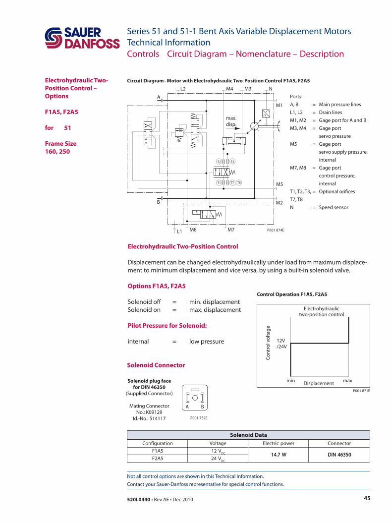
45520L0440 • Rev AE • Dec 2010
Series 51 and 51-1 Bent Axis Variable Displacement MotorsTechnical Information
Not all control options are shown in this Technical Information. Contact your Sauer-Danfoss representative for special control functions.
Electrohydraulic Two-Position Control – Options
F1A5, F2A5 for 51
Frame Size160, 250
Circuit Diagram – Motor with Electrohydraulic Two-Position Control F1A5, F2A5
Electrohydraulic Two-Position Control
Displacement can be changed electrohydraulically under load from maximum displace-ment to minimum displacement and vice versa, by using a built-in solenoid valve.
Options F1A5, F2A5
Solenoid off = min. displacementSolenoid on = max. displacement
Pilot Pressure for Solenoid:
internal = low pressure
min
12V/24V
maxDisplacement
Co
ntr
ol v
olt
age
Electrohydraulictwo-position control
P001 871E
Control Operation F1A5, F2A5
Solenoid Connector
Solenoid plug facefor DIN 46350
(Supplied Connector)
Mating ConnectorNo.: K09129
Id.-No.: 514117
A B
P001 752E
nmax.disp.
T2
T1
T3
T7 T8
P001 874E
L2 M4 M3 N
M1
L1
M2
M7M8
B
A
M5
Ports:A, B = Main pressure linesL1, L2 = Drain linesM1, M2 = Gage port for A and BM3, M4 = Gage port servo pressureM5 = Gage port servo supply pressure, internalM7, M8 = Gage port control pressure,
internalT1, T2, T3, = Optional orifices T7, T8N = Speed sensor
Controls Circuit Diagram – Nomenclature – Description
noitarugifnoC egatloV rewopcirtcelE rotcennoC
5A1F V21CD W7.41 05364NID
5A2F V42CD
W7.41 05364NID
Solenoid Data
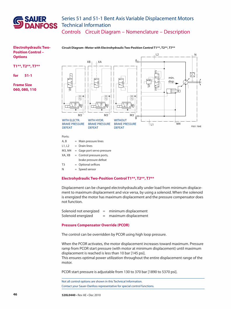
46 520L0440 • Rev AE • Dec 2010
Series 51 and 51-1 Bent Axis Variable Displacement MotorsTechnical Information
Not all control options are shown in this Technical Information. Contact your Sauer-Danfoss representative for special control functions.
Electrohydraulic Two-Position Control – Options
T1**, T2**, T7** for 51-1
Frame Size060, 080, 110
Circuit Diagram – Motor with Electrohydraulic Two-Position Control T1**, T2**, T7**
Electrohydraulic Two-Position Control T1**, T2**, T7**
Displacement can be changed electrohydraulically under load from minimum displace-ment to maximum displacement and vice versa, by using a solenoid. When the solenoid is energized the motor has maximum displacement and the pressure compensator does not function.
Solenoid not energized = minimum displacementSolenoid energized = maximum displacement
Pressure Compensator Override (PCOR)
The control can be overridden by PCOR using high loop pressure.
When the PCOR activates, the motor displacement increases toward maximum. Pressure ramp from PCOR start pressure (with motor at minimum displacement) until maximum displacement is reached is less than 10 bar [145 psi]. This ensures optimal power utilization throughout the entire displacement range of the motor.
PCOR start pressure is adjustable from 130 to 370 bar [1890 to 5370 psi].
Ports:A, B = Main pressure linesL1, L2 = Drain linesM3, M4 = Gage port servo pressureXA, XB = Control pressure ports, brake pressure defeatT3 = Optional orifices N = Speed sensor
Controls Circuit Diagram – Nomenclature – Description
n
T3
min.disp.
M4L1
NL2
A
BM3
T3
M3
WITH HYDR.BRAKE PRESSUREDEFEAT
T3
M3
WITH ELECTR.BRAKE PRESSUREDEFEAT
WITHOUTBRAKE PRESSUREDEFEAT P001 784E
XB XA
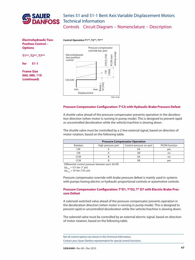
47520L0440 • Rev AE • Dec 2010
Series 51 and 51-1 Bent Axis Variable Displacement MotorsTechnical Information
Not all control options are shown in this Technical Information. Contact your Sauer-Danfoss representative for special control functions.
Circuit Diagram – Motor with Electrohydraulic Two-Position Control T1**, T2**, T7**
Pressure Compensator Configuration: T*CA with Hydraulic Brake Pressure Defeat
A shuttle valve ahead of the pressure compensator prevents operation in the decelera-tion direction (when motor is running in pump mode). This is designed to prevent rapid or uncontrolled deceleration while the vehicle/machine is slowing down.
The shuttle valve must be controlled by a 2-line external signal, based on direction of motor rotation, based on the following table.
Pressure compensator override with brake pressure defeat is mainly used in systems with pumps having electric or hydraulic proportional controls or automotive controls.
Pressure Compensator Configuration: T*D1, T*D2, T* D7 with Electric Brake Pres-sure Defeat
A solenoid-switched valve ahead of the pressure compensator prevents operation in the deceleration direction (when motor is running in pump mode). This is designed to prevent rapid or uncontrolled deceleration while the vehicle/machine is slowing down.
The solenoid valve must be controlled by an external electric signal, based on direction of motor rotation, based on the following table.
Electrohydraulic Two-Position Control – Options
T1**, T2**, T7** for 51-1
Frame Size060, 080, 110 (continued)
Controls Circuit Diagram – Nomenclature – Description
min.
12V/24V
max.Displacement
Electrohydraulictwo-position-control
PCO
R st
art
sett
ing
rang
e
Ram
p <
10 [1
45]
130
[189
0]37
0 [5
370
]
Pressure compensatoroverride bar, [psi]
P001 872E
Control Operation T1**, T2**, T7**
noitatoR troperusserphgiH tropnoerusserplortnoC noitcnuF-ROCP
WC A AX sey
WC A BX on
WCC B AX on
WCC B BX sey
BX/AXtropneewteberusserplortnoclaitnereffiD∆p
nim]isp7[rab5.0=
∆pxam
]isp527[rab05=
Pressure Compensator Operation

48 520L0440 • Rev AE • Dec 2010
Series 51 and 51-1 Bent Axis Variable Displacement MotorsTechnical Information
Not all control options are shown in this Technical Information. Contact your Sauer-Danfoss representative for special control functions.
Electrohydraulic Two-Position Control – Options
T1**, T2**, T7** for 51-1
Frame Size060, 080, 110 (continued)
Controls Circuit Diagram – Nomenclature – Description
Pressure Compensator Configuration: T*C2 without Brake Pressure Defeat
Pressure compensator functions when the motor is running in motor mode as well as in pump (deceleration) mode.
noitatoR troperusserphgiH dioneloS noitcnuF-ROCP
WC A dezigrene sey
WC A dezigrenenon on
WCC B dezigrene on
WCC B dezigrenenon sey
Pressure Compensator Operation
noitarugifnoCerusserphgiH
troptanoitknuF-ROCP
2C*T BdnaA sey
Pressure Compensator Options
Solenoid Connectors
Solenoid plug facefor DIN 46350
(Supplied Connector)
Mating ConnectorNo.: K09129
Id.-No.: 514117
A B
P001 752E
AMP Junior TimerTwo Pin Connector
(Supplied Connector)
Mating ConnectorNo.: K19815
Id.-No.: 508388
2 1
P001 751E
noitarugifnoC egatloV rewopcirtcelE rotcennoC
1D1T V21CD
W43 05364NID
7D7T V21CD
W43remiTroinuJPMArotcennocnipowt
2D2T V42CD
W43 05364NID
Solenoid Data
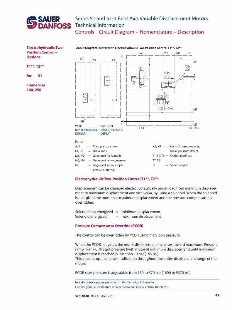
49520L0440 • Rev AE • Dec 2010
Series 51 and 51-1 Bent Axis Variable Displacement MotorsTechnical Information
Not all control options are shown in this Technical Information. Contact your Sauer-Danfoss representative for special control functions.
Electrohydraulic Two-Position Control – Options
T1**, T2** for 51
Frame Size 160, 250
Circuit Diagram – Motor with Electrohydraulic Two-Position Control T1**, T2**
Ports:A, B = Main pressure lines XA, XB = Control pressure ports,L1, L2 = Drain lines brake pressure defeatM1, M2 = Gage port for A and B T1, T2, T3, = Optional orificesM3, M4 = Gage port servo pressure T7, T8M5 = Gage port servo supply N = Speed sensor pressure internal
Controls Circuit Diagram – Nomenclature – Description
Electrohydraulic Two-Position Control T1**, T2**
Displacement can be changed electrohydraulically under load from minimum displace-ment to maximum displacement and vice versa, by using a solenoid. When the solenoid is energized the motor has maximum displacement and the pressure compensator is overridden.
Solenoid not energized = minimum displacementSolenoid energized = maximum displacement
Pressure Compensator Override (PCOR)
The control can be overridden by PCOR using high loop pressure.
When the PCOR activates, the motor displacement increases toward maximum. Pressure ramp from PCOR start pressure (with motor at minimum displacement) until maximum displacement is reached is less than 10 bar [145 psi]. This ensures optimal power utilization throughout the entire displacement range of the motor.
PCOR start pressure is adjustable from 130 to 370 bar [1890 to 5370 psi].
n
T3T2
T1 T7 T8
max.disp.
B
L2 M4 M3 N
M1
L1M2
M5
A
P001 785EWITHBRAKE PRESSUREDEFEAT
WITHOUTBRAKE PRESSUREDEFEAT
X4
XB
XA X4
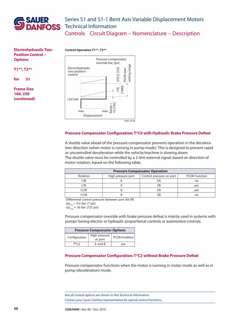
50 520L0440 • Rev AE • Dec 2010
Series 51 and 51-1 Bent Axis Variable Displacement MotorsTechnical Information
Not all control options are shown in this Technical Information. Contact your Sauer-Danfoss representative for special control functions.
Pressure Compensator Configuration: T*C0 with Hydraulic Brake Pressure Defeat
A shuttle valve ahead of the pressure compensator prevents operation in the decelera-tion direction (when motor is running in pump mode). This is designed to prevent rapid or uncontrolled deceleration while the vehicle/machine is slowing down.The shuttle valve must be controlled by a 2-line external signal, based on direction of motor rotation, based on the following table.
Pressure compensator override with brake pressure defeat is mainly used in systems with pumps having electric or hydraulic proportional controls or automotive controls.
Pressure Compensator Configuration: T*C2 without Brake Pressure Defeat
Pressure compensator functions when the motor is running in motor mode as well as in pump (deceleration) mode.
Electrohydraulic Two-Position Control – Options
T1**, T2** for 51
Frame Size 160, 250 (continued)
Controls Circuit Diagram – Nomenclature – Description
min.
12V/24V
max.Displacement
Electrohydraulictwo-position-control
PCO
R st
art
sett
ing
rang
e
Ram
p <
10 [1
45]
130
[189
0]37
0 [5
370
]
Pressure compensatoroverride bar, [psi]
P001 872E
Control Operation T1**, T2**
noitatoR troperusserphgiH tropnoerusserplortnoC noitcnuF-ROCP
WC A AX on
WC A BX sey
WCC B AX sey
WCC B BX on
BX/AXtropneewteberusserplortnoclaitnereffiD∆p
nim]isp7[rab5.0=
∆pxam
]isp527[rab05=
Pressure Compensator Operation
noitarugifnoCerusserphgiH
troptanoitknuF-ROCP
2C*T BdnaA sey
Pressure Compensator Options
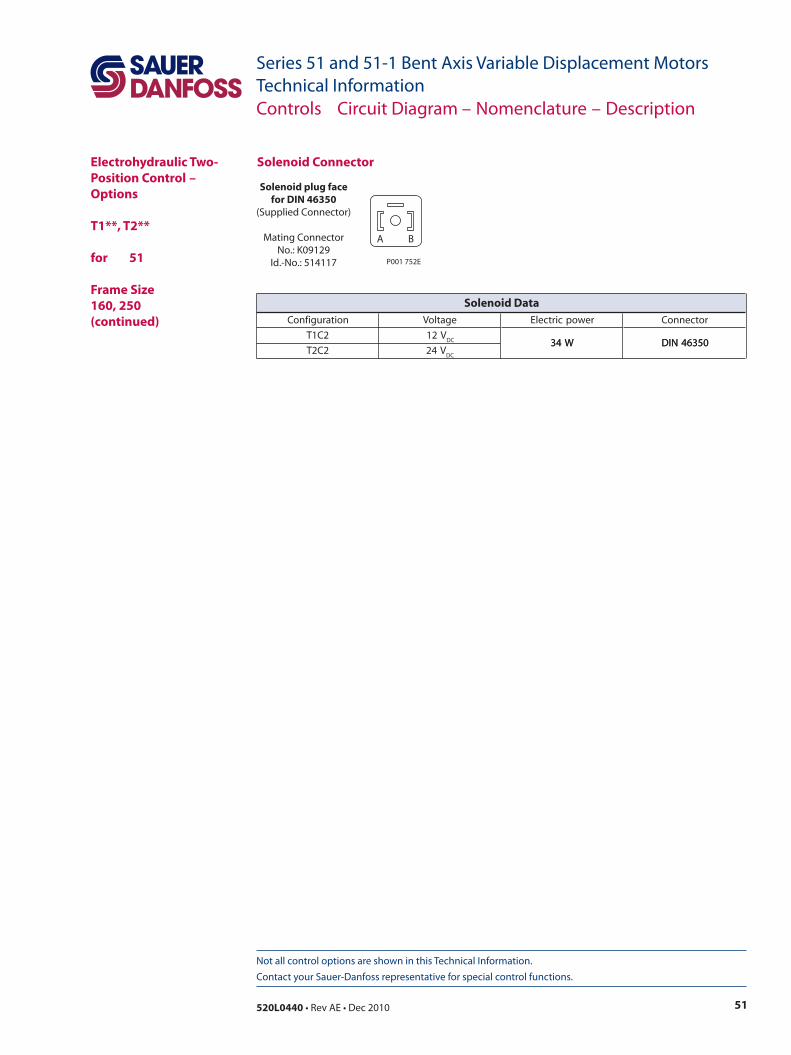
51520L0440 • Rev AE • Dec 2010
Series 51 and 51-1 Bent Axis Variable Displacement MotorsTechnical Information
Not all control options are shown in this Technical Information. Contact your Sauer-Danfoss representative for special control functions.
Solenoid Connector
Solenoid plug facefor DIN 46350
(Supplied Connector)
Mating ConnectorNo.: K09129
Id.-No.: 514117
A B
P001 752E
Electrohydraulic Two-Position Control – Options
T1**, T2** for 51
Frame Size 160, 250 (continued)
Controls Circuit Diagram – Nomenclature – Description
noitarugifnoC egatloV rewopcirtcelE rotcennoC
2C1T V21CD W43 05364NID
2C2T V42CD
W43 05364NID
Solenoid Data
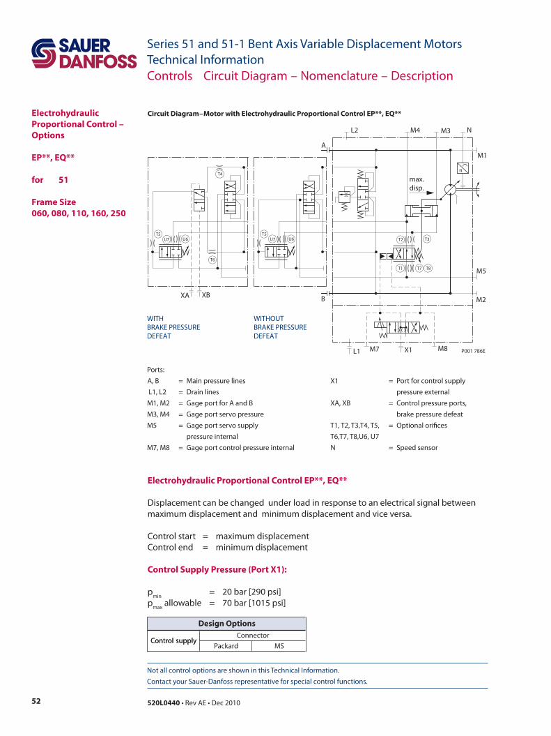
52 520L0440 • Rev AE • Dec 2010
Series 51 and 51-1 Bent Axis Variable Displacement MotorsTechnical Information
Not all control options are shown in this Technical Information. Contact your Sauer-Danfoss representative for special control functions.
Electrohydraulic Proportional Control – Options
EP**, EQ** for 51
Frame Size 060, 080, 110, 160, 250
Circuit Diagram – Motor with Electrohydraulic Proportional Control EP**, EQ**
Electrohydraulic Proportional Control EP**, EQ**
Displacement can be changed under load in response to an electrical signal between maximum displacement and minimum displacement and vice versa.
Control start = maximum displacementControl end = minimum displacement
Control Supply Pressure (Port X1):
pmin = 20 bar [290 psi]pmax allowable = 70 bar [1015 psi]
Ports: A, B = Main pressure lines X1 = Port for control supply L1, L2 = Drain lines pressure externalM1, M2 = Gage port for A and B XA, XB = Control pressure ports,M3, M4 = Gage port servo pressure brake pressure defeatM5 = Gage port servo supply T1, T2, T3,T4, T5, = Optional orifices pressure internal T6,T7, T8,U6, U7M7, M8 = Gage port control pressure internal N = Speed sensor
Controls Circuit Diagram – Nomenclature – Description
ylppuslortnoCrotcennoC
ylppuslortnoCdrakcaP SM
Design Options
n
T3
T7T1 T8
T2
max.disp.
A
L2 M4 M3 N
M1
L1
M2
M8M7 X1
M5
B
WITHBRAKE PRESSUREDEFEAT
WITHOUTBRAKE PRESSUREDEFEAT
P001 786E
T4
T6
U6U7T5
XA XB
U6U7T5
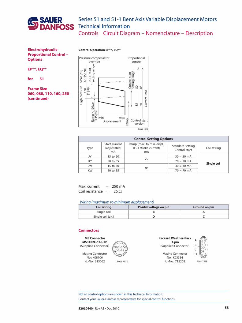
53520L0440 • Rev AE • Dec 2010
Series 51 and 51-1 Bent Axis Variable Displacement MotorsTechnical Information
Not all control options are shown in this Technical Information. Contact your Sauer-Danfoss representative for special control functions.
Co
ntr
ol s
tart
sett
ing
ran
ge
Ram
pmin max
5015
8550 Cu
rren
t m
A
Displacement
J K
Proportional control
PCO
R st
art
sett
ing
ran
ge
Ram
p <
10
bar
[145
psi
]
370
[537
0]13
0[1
890]
Hig
h p
ress
ure
p
bar
[psi
]
Pressure compensatoroverride
Control start version
P001 172E
Control Operation EP**, EQ**
Max. current = 250mACoil resistance = 26 Ω
Connectors
AB
DC
MS ConnectorMS3102C-14S-2P
(Supplied Connector)
Mating ConnectorNo.: K08106
Id.-No.: 615062 P001 753E
Packard Weather-Pack 4 pin
(Supplied Connector)
Mating ConnectorNo.: K03384
Id.-No.: 712208
A
B
CD
P001 759E
Electrohydraulic Proportional Control – Options
EP**, EQ** for 51
Frame Size 060, 080, 110, 160, 250 (continued)
Controls Circuit Diagram – Nomenclature – Description
epyTtnerructratS)elbatsujda(
Am
).lpsid.nimot.xam(pmaR)tnerrucekortslluF(
Am
gnittesdradnatStratslortnoC
gniriwlioC
YJ 05ot5107
Am03=03
liocelgniSYK 58ot05
07Am07=07
liocelgniSWJ 05ot51
59Am03=03
liocelgniS
WK 58ot0559
Am07=07
liocelgniS
Control Setting Options
Wiring (maximum to minimum displacement)Coil wiring Positiv voltage on pin Ground on pinSingle coil B A
Single coil (alt.) D C
54 520L0440 • Rev AE • Dec 2010
Series 51 and 51-1 Bent Axis Variable Displacement MotorsTechnical Information
Not all control options are shown in this Technical Information. Contact your Sauer-Danfoss representative for special control functions.
Pressure Compensator Override (PCOR)
The control can be overridden by PCOR using high loop pressure.
When the PCOR activates, the motor displacement increases to maximum. Pressure ramp from PCOR start pressure (with motor at minimum displacement) until maximum displacement is reached is less than 10 bar [145 psi] . This ensures optimal power utilization throughout the entire displacement range of the motor.
PCOR start pressure is adjustable from 130 to 370 bar [1890 to 5370 psi].
Pressure Compensator Override Configuration: EPA1, EQA1 with Brake Pressure Defeat
A shuttle valve ahead of the pressure compensator prevents operation in the decelera-tion direction (when motor is running in pump mode). This is designed to prevent rapid or uncontrolled deceleration while the vehicle/machine is slowing down.
The shuttle valve must be controlled by a 2-line external signal, based on direction of motor rotation, based on the following table. Pressure compensator override with brake pressure defeat is mainly used in systems with pumps having electric or hydraulic proportional controls or automotive controls.
Pressure Compensator Override Configuration: EPA2, EQA2 without Brake Pressure Defeat
The pressure compensator override functions when the motor is running in motor mode as well as in pump (deceleration) mode.
Electrohydraulic Proportional Control – Options
EP**, EQ** for 51 Frame Size 060, 080, 110, 160, 250 (continued)
Controls Circuit Diagram – Nomenclature – Description
noitatoR troperusserphgiH tropnoerusserplortnoC noitcnuF-ROCP
WC A AX on
WC A BX sey
WCC B AX sey
WCC B BX on
BX/AXtropneewteberusserplortnoclaitnereffiD∆p
nim]isp7[rab5.0=
∆pxam
]isp527[rab05=
Pressure Compensator Operation
noitarugifnoC troptaROCP daefederusserpekarB
1AQE/1APE B+A htiw
2AQE/2APE B+A tuohtiw
Configuration Options
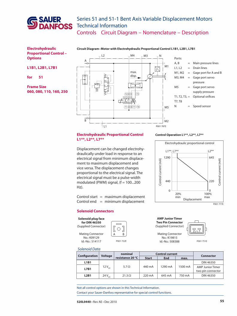
55520L0440 • Rev AE • Dec 2010
Series 51 and 51-1 Bent Axis Variable Displacement MotorsTechnical Information
Not all control options are shown in this Technical Information. Contact your Sauer-Danfoss representative for special control functions.
Electrohydraulic Proportional Control – Options
L1B1, L2B1, L7B1 for 51 Frame Size 060, 080, 110, 160, 250
Circuit Diagram – Motor with Electrohydraulic Proportional Control L1B1, L2B1, L7B1
n
T1
T2 T3
T7 T8
max.disp.
P001 787E
B
A
L2 M4 M3 N
M1
M5
L1
M2
Electrohydraulic Proportional Control L1**, L2**, L7**
Displacement can be changed electrohy-draulically under load in response to an electrical signal from minimum displace-ment to maximum displacement and vice versa. The displacement changes proportional to the electrical signal. The electrical signal must be a pulse-width modulated (PWM) signal, (f = 100...200 Hz).
Control start = maximum displacementControl end = minimum displacement
Solenoid Connectors
Solenoid plug facefor DIN 46350
(Supplied Connector)
Mating ConnectorNo.: K09129
Id.-No.: 514117
A B
P001 752E
AMP Junior TimerTwo Pin Connector
(Supplied Connector)
Mating ConnectorNo.: K19815
Id.-No.: 508388
2 1
P001 751E
Ports:A, B = Main pressure linesL1, L2 = Drain linesM1, M2 = Gage port for A and BM3, M4 = Gage port servo
pressureM5 = Gage port servo supply pressureT1, T2, T3, = Optional orifices T7, T8N = Speed sensor
Controls Circuit Diagram – Nomenclature – Description
1290
440
0
645
220
020%min
100%max
Co
ntr
ol c
urr
ent
(mA
)
Co
ntr
ol c
urr
ent
(mA
)
Displacement
Electrohydraulic proportional control
L1**, L7** L2**
P001 777E
Control Operation L1**, L2**, L7**
Solenoid Data
Configuration Voltage nominal resistance 20 °C
Control current ConnectorStart End max.
L1B112 VDC 5.7 Ω 440 mA 1290 mA 1500 mA
DIN 46350
L7B1 AMP Junior Timertwo pin connector
L2B1 24 VDC 21.3 Ω 220 mA 645 mA 750 mA DIN 46350
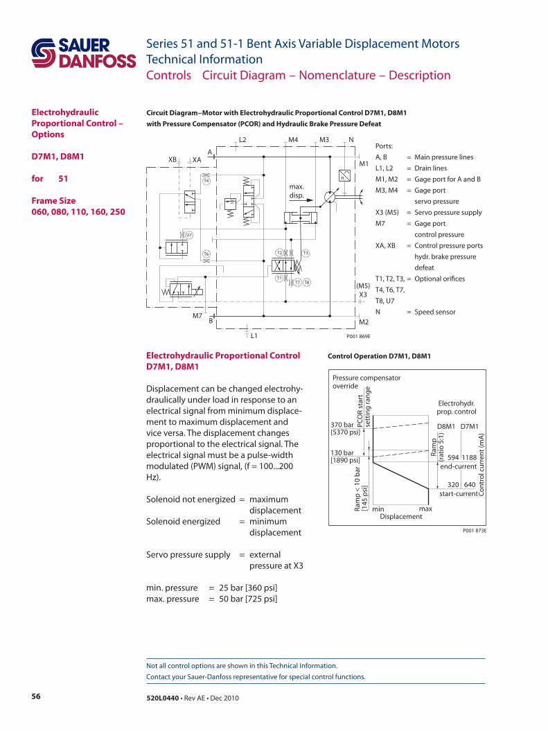
56 520L0440 • Rev AE • Dec 2010
Series 51 and 51-1 Bent Axis Variable Displacement MotorsTechnical Information
Not all control options are shown in this Technical Information. Contact your Sauer-Danfoss representative for special control functions.
Electrohydraulic Proportional Control – Options
D7M1, D8M1 for 51
Frame Size 060, 080, 110, 160, 250
Circuit Diagram – Motor with Electrohydraulic Proportional Control D7M1, D8M1 with Pressure Compensator (PCOR) and Hydraulic Brake Pressure Defeat
nT4
T6 T2 T3
T1T7 T8
U7
max.disp.
B
XB XA
M7
A
L2 M4 M3 N
M1
L1
M2
(M5)X3
P001 869E
Control Operation D7M1, D8M1
Ports:A, B = Main pressure linesL1, L2 = Drain linesM1, M2 = Gage port for A and BM3, M4 = Gage port servo pressureX3 (M5) = Servo pressure supplyM7 = Gage port control pressureXA, XB = Control pressure ports hydr. brake pressure
defeatT1, T2, T3, = Optional orificesT4, T6, T7,T8, U7N = Speed sensor
Electrohydraulic Proportional Control D7M1, D8M1
Displacement can be changed electrohy-draulically under load in response to an electrical signal from minimum displace-ment to maximum displacement and vice versa. The displacement changes proportional to the electrical signal. The electrical signal must be a pulse-width modulated (PWM) signal, (f = 100...200 Hz). Solenoid not energized = maximum displacementSolenoid energized = minimum displacement Servo pressure supply = external pressure at X3 min. pressure = 25 bar [360 psi]max. pressure = 50 bar [725 psi]
Ram
p(r
atio
5:1
)
min max
start-current
end-current
320 640
594
D8M1 D7M1
1188
Displacement
Electrohydr.prop. control
PCO
R st
art
sett
ing
rang
e
Pressure compensatoroverride
370 bar[5370 psi]
130 bar[1890 psi]
Ram
p <
10 b
ar[1
45 p
si]
Cont
rol c
urre
nt (m
A)
P001 873E
Controls Circuit Diagram – Nomenclature – Description
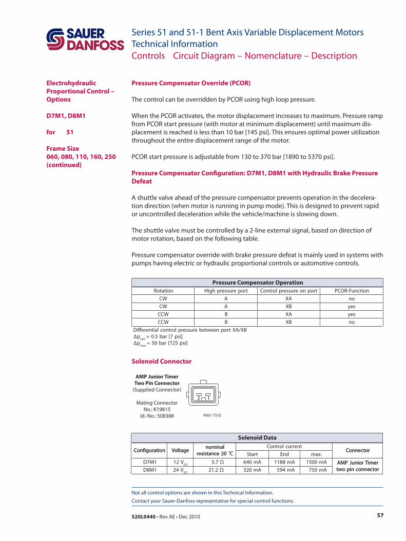
57520L0440 • Rev AE • Dec 2010
Series 51 and 51-1 Bent Axis Variable Displacement MotorsTechnical Information
Not all control options are shown in this Technical Information. Contact your Sauer-Danfoss representative for special control functions.
Solenoid Connector
Pressure Compensator Override (PCOR)
The control can be overridden by PCOR using high loop pressure.
When the PCOR activates, the motor displacement increases to maximum. Pressure ramp from PCOR start pressure (with motor at minimum displacement) until maximum dis-placement is reached is less than 10 bar [145 psi]. This ensures optimal power utilization throughout the entire displacement range of the motor.
PCOR start pressure is adjustable from 130 to 370 bar [1890 to 5370 psi].
Pressure Compensator Configuration: D7M1, D8M1 with Hydraulic Brake Pressure Defeat
A shuttle valve ahead of the pressure compensator prevents operation in the decelera-tion direction (when motor is running in pump mode). This is designed to prevent rapid or uncontrolled deceleration while the vehicle/machine is slowing down.
The shuttle valve must be controlled by a 2-line external signal, based on direction of motor rotation, based on the following table.
Pressure compensator override with brake pressure defeat is mainly used in systems with pumps having electric or hydraulic proportional controls or automotive controls.
AMP Junior TimerTwo Pin Connector
(Supplied Connector)
Mating ConnectorNo.: K19815
Id.-No.: 508388
2 1
P001 751E
Electrohydraulic Proportional Control – Options
D7M1, D8M1 for 51 Frame Size 060, 080, 110, 160, 250 (continued)
Controls Circuit Diagram – Nomenclature – Description
noitatoR troperusserphgiH tropnoerusserplortnoC noitcnuF-ROCP
WC A AX on
WC A BX sey
WCC B AX sey
WCC B BX on
BX/AXtropneewteberusserplortnoclaitnereffiD∆p
nim]isp7[rab5.0=
∆pxam
]isp527[rab05=
Pressure Compensator Operation
noitarugifnoC egatloVlanimon
C˚02ecnatsisertnerruclortnoC
rotcennoCnoitarugifnoC egatloVlanimon
C˚02ecnatsiser tratS dnE .xamrotcennoC
1M7D V21CD
7.5 Ω Am046 Am8811 Am0051 remiTroinuJPMArotcennocnipowt1M8D V42
CD2.12 Ω Am023 Am495 Am057
remiTroinuJPMArotcennocnipowt
Solenoid Data
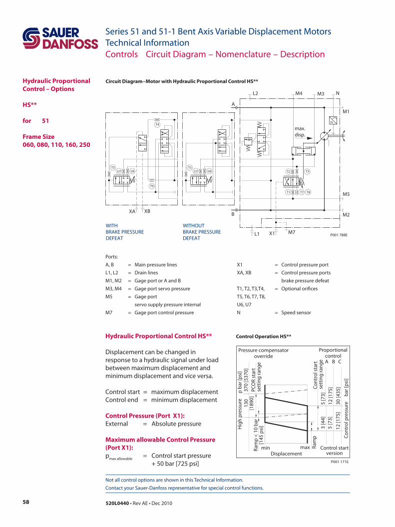
58 520L0440 • Rev AE • Dec 2010
Series 51 and 51-1 Bent Axis Variable Displacement MotorsTechnical Information
Not all control options are shown in this Technical Information. Contact your Sauer-Danfoss representative for special control functions.
Hydraulic Proportional Control – Options
HS**
for 51
Frame Size 060, 080, 110, 160, 250
Circuit Diagram – Motor with Hydraulic Proportional Control HS**
Hydraulic Proportional Control HS**
Displacement can be changed in response to a hydraulic signal under load between maximum displacement and minimum displacement and vice versa. Control start = maximum displacementControl end = minimum displacement
Control Pressure (Port X1):External = Absolute pressure
Maximum allowable Control Pressure (Port X1):pmax allowable = Control start pressure + 50 bar [725 psi]
Ports:A, B = Main pressure lines X1 = Control pressure portL1, L2 = Drain lines XA, XB = Control pressure portsM1, M2 = Gage port or A and B brake pressure defeatM3, M4 = Gage port servo pressure T1, T2, T3,T4, = Optional orificesM5 = Gage port T5, T6, T7, T8, servo supply pressure internal U6, U7M7 = Gage port control pressure N = Speed sensor
Controls Circuit Diagram – Nomenclature – Description
Cont
rol s
tart
sett
ing
rang
eRa
mp
min
Cont
rol p
ress
ure
bar
[psi
]
Displacement
A
Proportionalcontrol
PCO
R st
art
sett
ing
rang
eRa
mp
< 10
bar
[145
psi
]
370
[537
0]13
0[1
890]
Hig
h pr
essu
re
p b
ar [p
si]
Pressure compensatoroverride
Control startversion
5 [7
3]12
[175
]30
[435
]
3 [4
4] 5
[73]
12
[175
]
B C
max
P001 171E
Control Operation HS**
T4
T6
U6U7T5
XA XB
WITHBRAKE PRESSUREDEFEAT
WITHOUTBRAKE PRESSUREDEFEAT
U6U7T5
n
T3
T7T1 T8
T2
max.disp.
A
L2 M4 M3 N
M1
L1
M2
P001 788E
M5
B
M7X1
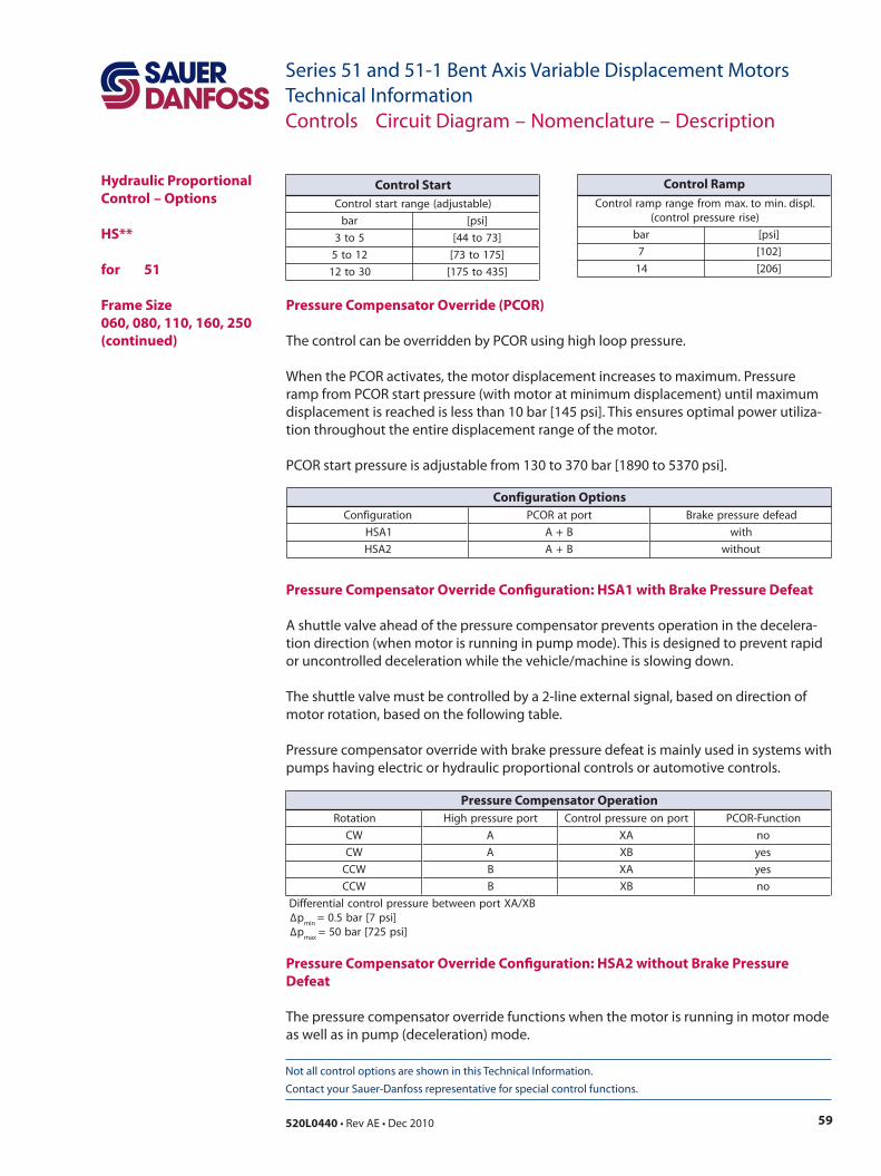
59520L0440 • Rev AE • Dec 2010
Series 51 and 51-1 Bent Axis Variable Displacement MotorsTechnical Information
Not all control options are shown in this Technical Information. Contact your Sauer-Danfoss representative for special control functions.
Pressure Compensator Override (PCOR)
The control can be overridden by PCOR using high loop pressure.
When the PCOR activates, the motor displacement increases to maximum. Pressure ramp from PCOR start pressure (with motor at minimum displacement) until maximum displacement is reached is less than 10 bar [145 psi]. This ensures optimal power utiliza-tion throughout the entire displacement range of the motor.
PCOR start pressure is adjustable from 130 to 370 bar [1890 to 5370 psi].
Pressure Compensator Override Configuration: HSA1 with Brake Pressure Defeat
A shuttle valve ahead of the pressure compensator prevents operation in the decelera-tion direction (when motor is running in pump mode). This is designed to prevent rapid or uncontrolled deceleration while the vehicle/machine is slowing down.
The shuttle valve must be controlled by a 2-line external signal, based on direction of motor rotation, based on the following table.
Pressure compensator override with brake pressure defeat is mainly used in systems with pumps having electric or hydraulic proportional controls or automotive controls.
Pressure Compensator Override Configuration: HSA2 without Brake Pressure Defeat
The pressure compensator override functions when the motor is running in motor mode as well as in pump (deceleration) mode.
Hydraulic Proportional Control – Options
HS**
for 51 Frame Size 060, 080, 110, 160, 250 (continued)
Controls Circuit Diagram – Nomenclature – Description
noitatoR troperusserphgiH tropnoerusserplortnoC noitcnuF-ROCP
WC A AX on
WC A BX sey
WCC B AX sey
WCC B BX on
BX/AXtropneewteberusserplortnoclaitnereffiD∆p
nim]isp7[rab5.0=
∆pxam
]isp527[rab05=
Pressure Compensator Operation
)elbatsujda(egnartratslortnoC
rab ]isp[
5ot3 ]37ot44[
21ot5 ]571ot37[
03ot21 ]534ot571[
Control Start.lpsid.nimot.xammorfegnarpmarlortnoC
)esirerusserplortnoc(
rab ]isp[
7 ]201[
41 ]602[
Control Ramp
noitarugifnoC troptaROCP daefederusserpekarB
1ASH B+A htiw
2ASH B+A tuohtiw
Configuration Options
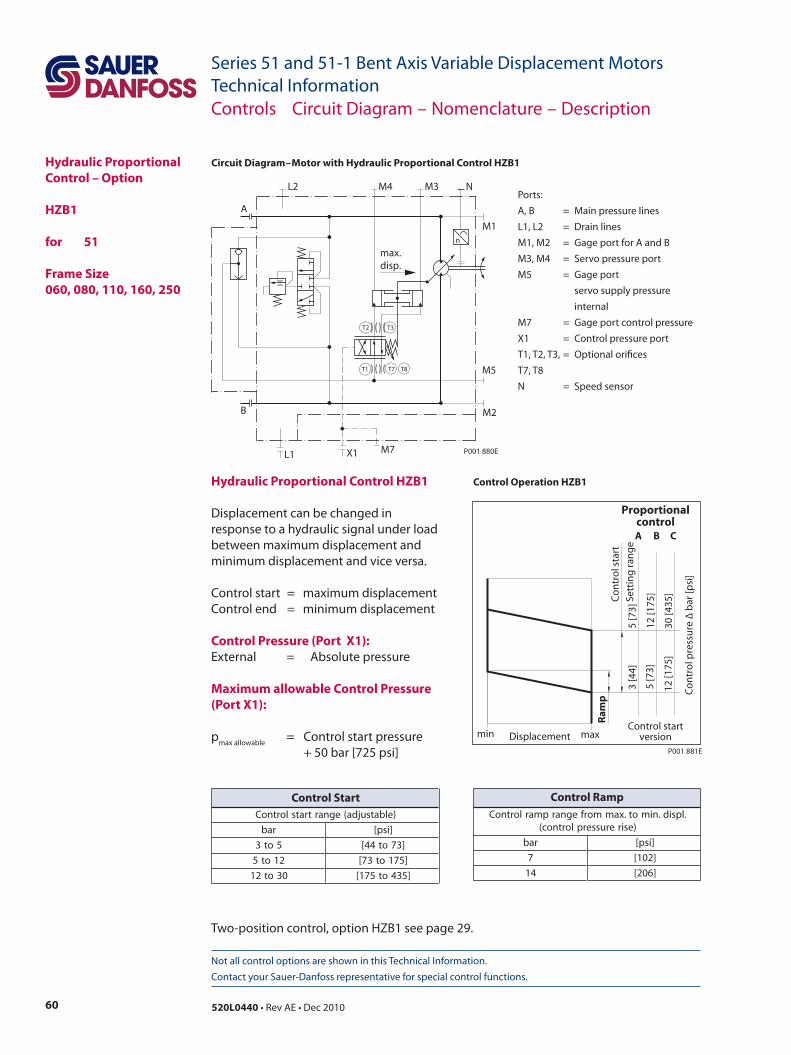
60 520L0440 • Rev AE • Dec 2010
Series 51 and 51-1 Bent Axis Variable Displacement MotorsTechnical Information
Not all control options are shown in this Technical Information. Contact your Sauer-Danfoss representative for special control functions.
Controls Circuit Diagram – Nomenclature – Description
Hydraulic Proportional Control – Option
HZB1 for 51
Frame Size060, 080, 110, 160, 250
Circuit Diagram – Motor with Hydraulic Proportional Control HZB1
T2 T3
T7 T8T1
max.disp.
M2
X1 M7
B
M5
L1
M1
M4L2
A
M3 N
P001 880E
n
Ports:A, B = Main pressure linesL1, L2 = Drain linesM1, M2 = Gage port for A and BM3, M4 = Servo pressure portM5 = Gage port servo supply pressure
internalM7 = Gage port control pressureX1 = Control pressure portT1, T2, T3, = Optional orificesT7, T8N = Speed sensor
Co
ntr
ol s
tart
Sett
ing
ran
ge
Ram
p
min max
Co
ntr
ol p
ress
ure
∆ b
ar [p
si]
Displacement
A
Proportionalcontrol
Control startversion
5 [7
3]
12 [1
75]
30 [4
35]
3 [4
4]
5 [7
3]
12
[175
]
B C
P001 881E
Control Operation HZB1Hydraulic Proportional Control HZB1
Displacement can be changed in response to a hydraulic signal under load between maximum displacement and minimum displacement and vice versa. Control start = maximum displacementControl end = minimum displacement
Control Pressure (Port X1):External = Absolute pressure
Maximum allowable Control Pressure (Port X1):
pmax allowable = Control start pressure + 50 bar [725 psi]
Two-position control, option HZB1 see page 29.
)elbatsujda(egnartratslortnoC
rab ]isp[
5ot3 ]37ot44[
21ot5 ]571ot37[
03ot21 ]534ot571[
Control Start.lpsid.nimot.xammorfegnarpmarlortnoC
)esirerusserplortnoc(
rab ]isp[
7 ]201[
41 ]602[
Control Ramp
61520L0440 • Rev AE • Dec 2010
Series 51 and 51-1 Bent Axis Variable Displacement MotorsTechnical InformationNotes
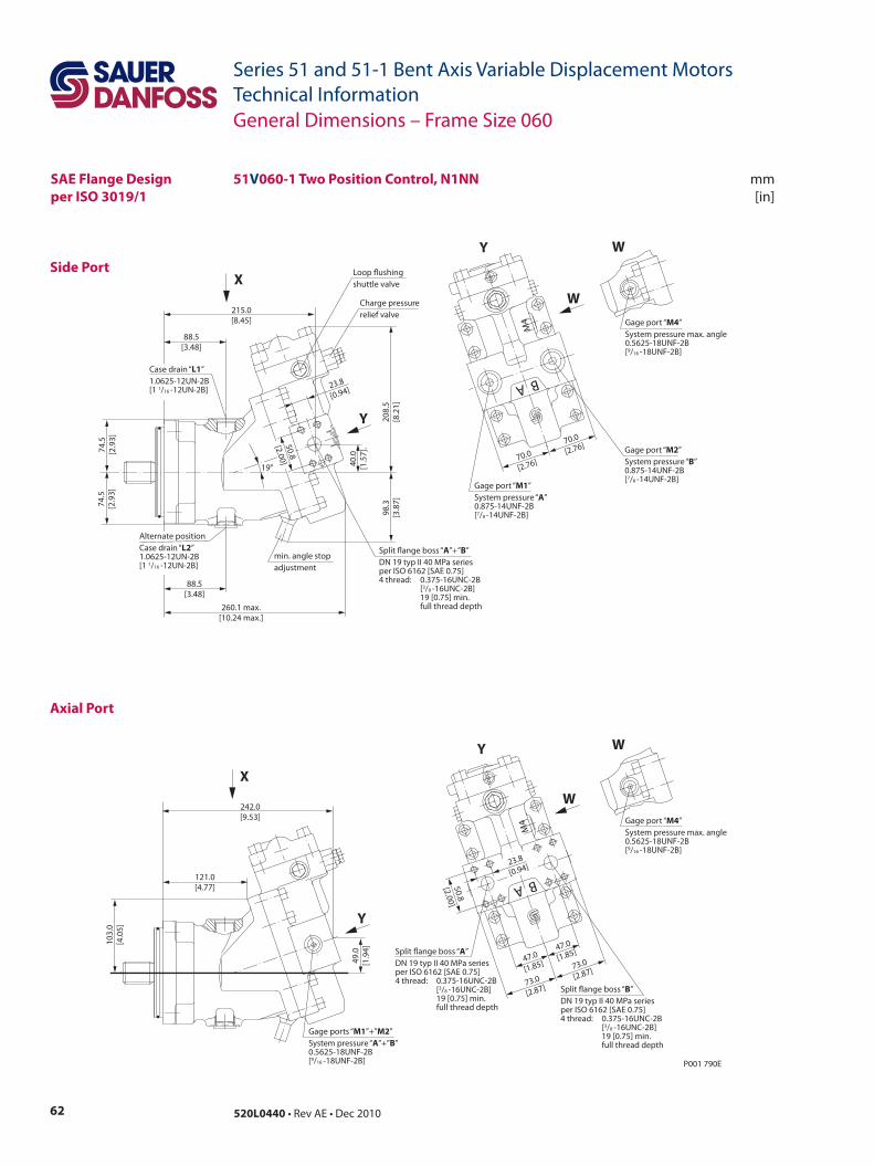
62 520L0440 • Rev AE • Dec 2010
Series 51 and 51-1 Bent Axis Variable Displacement MotorsTechnical Information
mm[in]
Side Port
Axial Port
51V060-1 Two Position Control, N1NN
P001 790E
88.5[3.48]
88.5[3.48]
40.0
[1.5
7].
19°
Loop ushingshuttle valve
Charge pressurerelief valve
min. angle stopadjustment
215.0[8.45]
260.1 max.[10.24 max.]
74.5
[2.9
3]74
.5[2
.93]
208.
5[8
.21]
98.3
[3.8
7]
Split ange boss “A”+”B”DN 19 typ II 40 MPa seriesper ISO 6162 [SAE 0.75]4 thread: 0.375-16UNC-2B [3/8 -16UNC-2B] 19 [0.75] min. full thread depth
A B
M4
70.0
[2.76]
70.0
[2.76]
Case drain “L1”1.0625-12UN-2B[1 1/16 -12UN-2B]
Alternate positionCase drain “L2”1.0625-12UN-2B[1 1/16 -12UN-2B]
50.8
[2.00]
23.8
[0.94]
Gage port “M1”System pressure “A” 0.875-14UNF-2B[7/8 -14UNF-2B]
Gage port “M2”System pressure “B” 0.875-14UNF-2B[7/8 -14UNF-2B]
49.0
[1.9
4]
103.
0[4
.05]
242.0[9.53]
121.0[4.77] A B
M4
47.0
[1.85]
50.8
[2.00]
73.0
[2.87]
73.0
[2.87]
47.0
[1.85]
23.8
[0.94]
Gage ports “M1”+”M2”System pressure “A”+”B” 0.5625-18UNF-2B[9/16 -18UNF-2B]
Split ange boss “A”DN 19 typ II 40 MPa seriesper ISO 6162 [SAE 0.75]4 thread: 0.375-16UNC-2B [3/8 -16UNC-2B] 19 [0.75] min. full thread depth
Split ange boss “B”DN 19 typ II 40 MPa seriesper ISO 6162 [SAE 0.75]4 thread: 0.375-16UNC-2B [3/8 -16UNC-2B] 19 [0.75] min. full thread depth
Y
Y
X
X
W
W
Y
Y
Gage port “M4”System pressure max. angle0.5625-18UNF-2B[9/16 -18UNF-2B]
W
Gage port “M4”System pressure max. angle0.5625-18UNF-2B[9/16 -18UNF-2B]
W
General Dimensions – Frame Size 060
SAE Flange Designper ISO 3019/1
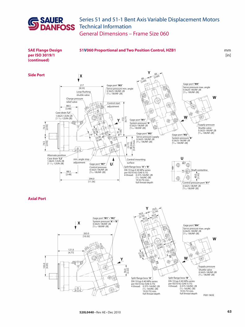
63520L0440 • Rev AE • Dec 2010
Series 51 and 51-1 Bent Axis Variable Displacement MotorsTechnical Information
mm[in]
Side Port
Axial Port
General Dimensions – Frame Size 060
SAE Flange Designper ISO 3019/1(continued)
51V060 Proportional and Two Position Control, HZB1
A
M3
M1
M5
L1
L2
L1
L2
263.0[10.35]
121.0[4.77]
P001 965E
56.0
[2.2
2]103.
0[4
.05]
Y
X
88.5[3.48]
88.5[3.48]
294.0[11.56]
74.5
[2.9
3]74
.5[2
.93]
172
[6.7
7]96
[3.7
7]
41[1
.60]
217[8.53]
19°
50.80
[2.00]
Y
23.90
[0.94]
X
U
98 m
ax.
[3.8
7] m
ax.
Supply pressureShuttle valve0.5625-18UNF-2B[9/16 -18UNF-2B]
Gage port “M4”Servo pressure max. angle0.5625-18UNF-2B[9/16 -18UNF-2B]
W
W
M4
Shaft centerline
Control pressure port “X1”0.5625-18UNF-2B[9/16 -18UNF-2B]
U
X1
M7
49.0
[1.9
3]
Supply pressureShuttle valve0.5625-18UNF-2B[9/16 -18UNF-2B]
Gage port “M4”Servo pressure max. angle0.5625-18UNF-2B[9/16 -18UNF-2B]
W
W
M4
45.0
[1.77]45.0
[1.77]
70.0
[2.76]
70.0
[2.76]
50.80
[2.00]
BA
M5
M3
M4
23.80
[0.94]
Y
Split ange boss “A”DN 19 typ II 40 MPa seriesper ISO 6162 [SAE 0.75]4 thread: 0.375-16UNC-2B [3/8 -16UNC-2B] 19 [0.75] min. full thread depth
Split ange boss “B”DN 19 typ II 40 MPa seriesper ISO 6162 [SAE 0.75]4 thread: 0.375-16UNC-2B [3/8 -16UNC-2B] 19 [0.75] min. full thread depth
Gage port “M1”+”M2”System pressure “A”+”B”0.5625-18UNF-2B[9/16 -18UNF-2B]
66[2.60]
66[2.60]
Y
Gage port “M2”System pressure “B” 0.5625-18UNF-2B[9/16 -18UNF-2B]
Gage port “M1”System pressure “A” 0.5625-18UNF-2B[9/16 -18UNF-2B]
Gage port “M5”Servo pressure supply0.5625-18UNF-2B[9/16 -18UNF-2B]
Control mountingsurface
Split ange boss “A”+”B”DN 19 typ II 40 MPa seriesper ISO 6162 [SAE 0.75]4 thread: 0.375-16UNC-2B [3/8 -16UNC-2B] 19 [0.75] min. full thread depth
min. angle stopadjustment Gage port “M7”
Control pressure0.5625-18UNF-2B[9/16 -18UNF-2B]
Alternate positionCase drain “L2”1.0625-12UN-2B[1 1/16 -12UN-2B]
Gage port “M3”Servo pressure min. angle0.5625-18UNF-2B[9/16 -18UNF-2B]
Control startadjustment
Loop ushingshuttle valve
Charge pressurerelief valve
Case drain “L1”1.0625-12UN-2B[1 1/16 -12UN-2B]
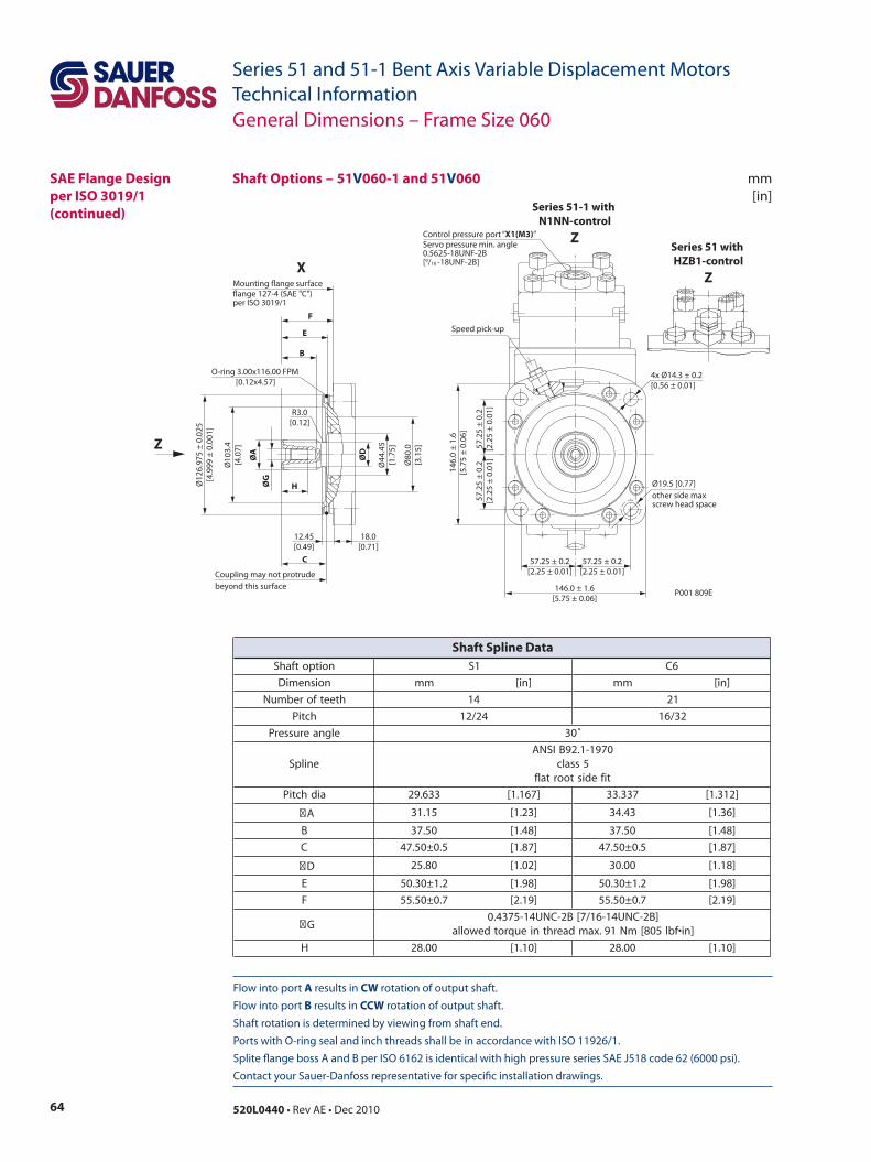
64 520L0440 • Rev AE • Dec 2010
Series 51 and 51-1 Bent Axis Variable Displacement MotorsTechnical Information
Flow into port A results in CW rotation of output shaft. Flow into port B results in CCW rotation of output shaft. Shaft rotation is determined by viewing from shaft end. Ports with O-ring seal and inch threads shall be in accordance with ISO 11926/1. Splite flange boss A and B per ISO 6162 is identical with high pressure series SAE J518 code 62 (6000 psi). Contact your Sauer-Danfoss representative for specific installation drawings.
mm[in]
SAE Flange Design per ISO 3019/1(continued)
Ø12
6.97
5 ±
0.02
5[4
.999
± 0
.001
]
Ø80
.0[3
.15]
Ø44
.45
[1.7
5]
ØG
ØD
ØA
Ø10
3.4
[4.0
7]
H
F
Mounting ange surfaceange 127-4 (SAE "C")per ISO 3019/1
E
B
C
Coupling may not protrudebeyond this surface
12.45[0.49]
18.0[0.71]
P001 809E
57.2
5 ±
0.2
[2.2
5 ±
0.01
]
57.25 ± 0.2[2.25 ± 0.01]
57.25 ± 0.2[2.25 ± 0.01]
4x Ø14.3 ± 0.2[0.56 ± 0.01]
57.2
5 ±
0.2
[2.2
5 ±
0.01
]
146.
0 ±
1.6
[5.7
5 ±
0.06
]
146.0 ± 1.6[5.75 ± 0.06]
Speed pick-up
Ø19.5 [0.77]other side maxscrew head space
R3.0[0.12]
Control pressure port “X1(M3)”Servo pressure min. angle0.5625-18UNF-2B[9/16 -18UNF-2B]
O-ring 3.00x116.00 FPM [0.12x4.57]
X
Z
Series 51 with HZB1-control
Z
Series 51-1 with N1NN-control
Z
General Dimensions – Frame Size 060
Shaft Options – 51V060-1 and 51V060
noitpotfahS 1S 6C
noisnemiD mm ]ni[ mm ]ni[
hteetforebmuN 41 12
hctiP 42/21 23/61
elgnaerusserP ˚03
enilpS0791-1.29BISNA
5ssalctifedistoortalf
aidhctiP 336.92 ]761.1[ 733.33 ]213.1[
A 51.13 ]32.1[ 34.43 ]63.1[
B 05.73 ]84.1[ 05.73 ]84.1[
C 5.0±05.74 ]78.1[ 5.0±05.74 ]78.1[
D 08.52 ]20.1[ 00.03 ]81.1[
E 2.1±03.05 ]89.1[ 2.1±03.05 ]89.1[
F 7.0±05.55 ]91.2[ 7.0±05.55 ]91.2[
G]B2-CNU41-61/7[B2-CNU41-5734.0
]ni•fbl508[mN19.xamdaerhtnieuqrotdewolla
H 00.82 ]01.1[ 00.82 ]01.1[
Shaft Spline Data
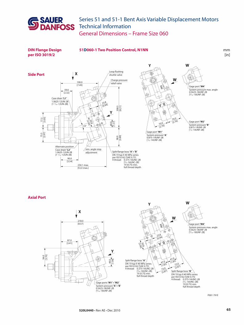
65520L0440 • Rev AE • Dec 2010
Series 51 and 51-1 Bent Axis Variable Displacement MotorsTechnical Information
mm[in]
Side Port
Axial Port
51D060-1 Two Position Control, N1NN
P001 791E
49.0
[1.9
4]94.0
[3.7
0]
218.0[8.57]
87.0[3.41]
90.0[3.54]
59.0[2.32]
40.0
[1.5
7]
19°
190.0[7.49]
234.1 max.[9.22 max.]
77.5
[3.0
5]75
.5[2
.97]
208.
5[8
.21]
98.9
[3.8
9]
23.8
[0.94]
A B
M4
47.0
[1.85]
50.8
[2.00]
73.0
[2.87]
73.0
[2.87]
47.0
[1.85]
23.8
[0.94]
Split ange boss “A”DN 19 typ II 40 MPa seriesper ISO 6162 [SAE 0.75]4 thread: 0.375-16UNC-2B [3/8 -16UNC-2B] 19 [0.75] min. full thread depth
Split ange boss “B”DN 19 typ II 40 MPa seriesper ISO 6162 [SAE 0.75]4 thread: 0.375-16UNC-2B [3/8 -16UNC-2B] 19 [0.75] min. full thread depth
W
Y
Gage port “M4”System pressure max. angle0.5625-18UNF-2B[9/16 -18UNF-2B]
W
A B
M4
70.0
[2.76]
70.0
[2.76]
Gage port “M1”System pressure “A” 0.875-14UNF-2B[7/8 -14UNF-2B]
Gage port “M2”System pressure “B” 0.875-14UNF-2B[7/8 -14UNF-2B]
W
Y
Gage port “M4”System pressure max. angle0.5625-18UNF-2B[9/16 -18UNF-2B]
WLoop ushingshuttle valve
Charge pressurerelief valve
min. angle stopadjustment Split ange boss “A”+”B”
DN 19 typ II 40 MPa seriesper ISO 6162 [SAE 0.75]4 thread: 0.375-16UNC-2B [3/8 -16UNC-2B] 19 [0.75] min. full thread depth
Case drain “L1”1.0625-12UN-2B[1 1/16 -12UN-2B]
Alternate positionCase drain “L2”1.0625-12UN-2B[1 1/16 -12UN-2B]
Y
X
Y
X
Gage ports “M1”+”M2”System pressure “A”+”B” 0.5625-18UNF-2B[9/16 -18UNF-2B]
50.8
[2.00]
General Dimensions – Frame Size 060
DIN Flange Designper ISO 3019/2
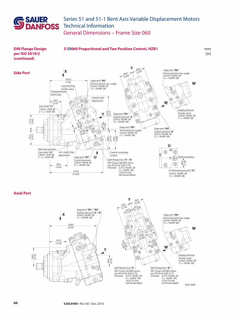
66 520L0440 • Rev AE • Dec 2010
Series 51 and 51-1 Bent Axis Variable Displacement MotorsTechnical Information
mm[in]
Side Port
Axial Port
General Dimensions – Frame Size 060
51D060 Proportional and Two Position Control, HZB1DIN Flange Designper ISO 3019/2(continued)
A
M3
M1
M5
L1
L2
45.0
[1.77]45.0
[1.77]
50.80
[2.00]
70.0
[2.76]
70.0
[2.76]Y
Split ange boss “A”DN 19 typ II 40 MPa seriesper ISO 6162 [SAE 0.75]4 thread: 0.375-16UNC-2B [3/8 -16UNC-2B] 19 [0.75] min. full thread depth
Split ange boss “B”DN 19 typ II 40 MPa seriesper ISO 6162 [SAE 0.75]4 thread: 0.375-16UNC-2B [3/8 -16UNC-2B] 19 [0.75] min. full thread depth
Gage port “M1”+”M2”System pressure “A”+”B”0.5625-18UNF-2B[9/16 -18UNF-2B]
238.0[9.39]
56.0
[2.2
2]94.0
[3.7
0]
87.0[3.45]
Y
X
90.0[3.54]
59.0[2.32]
Control startadjustment
Gage port “M3”Servo pressure min. angle0.5625-18UNF-2B[9/16 -18UNF-2B]
Gage port “M5”Servo pressure supply0.5625-18UNF-2B[9/16 -18UNF-2B]
Control mountingsurface
P001 966E
Loop ushingshuttle valve
270.0[10.64]
77.5
[3.0
5]75
.5[2
.97]
172.
0[6
.77]
96.0
[3.7
7]
41.0
[1.6
0]
192.0[7.56]
19°
Case drain “L1”1.0625-12UN-2B[1 1/16 -12UN-2B]
50.80
[2.00]
Y
23.90
[0.94]
X
USplit ange boss “A”+”B”DN 19 typ II 40 MPa seriesper ISO 6162 [SAE 0.75]4 thread: 0.375-16UNC-2B [3/8 -16UNC-2B] 19 [0.75] min. full thread depth
Gage port “M7”Control pressure0.5625-18UNF-2B[9/16 -18UNF-2B]
99.0
[3.8
9]
min. angle stopadjustment
Charge pressurerelief valve
Alternate positionCase drain “L2”1.0625-12UN-2B[1 1/16 -12UN-2B]
Gage port “M2”System pressure “B” 0.5625-18UNF-2B[9/16 -18UNF-2B]
Gage port “M1”System pressure “A” 0.5625-18UNF-2B[9/16 -18UNF-2B]
66.0
[2.60]
66.0
[2.60]Y
L1
L2
AB
M3
M5
M4
23.80
[0.94]
Supply pressureShuttle valve0.5625-18UNF-2B[9/16 -18UNF-2B]
Gage port “M4”Servo pressure max. angle0.5625-18UNF-2B[9/16 -18UNF-2B]
W
W
M4
Shaft centerline
Control pressure port “X1”0.5625-18UNF-2B[9/16 -18UNF-2B]
U
X1
M7
49.0
[1.9
3]
Supply pressureShuttle valve0.5625-18UNF-2B[9/16 -18UNF-2B]
Gage port “M4”Servo pressure max. angle0.5625-18UNF-2B[9/16 -18UNF-2B]
W
W
M4
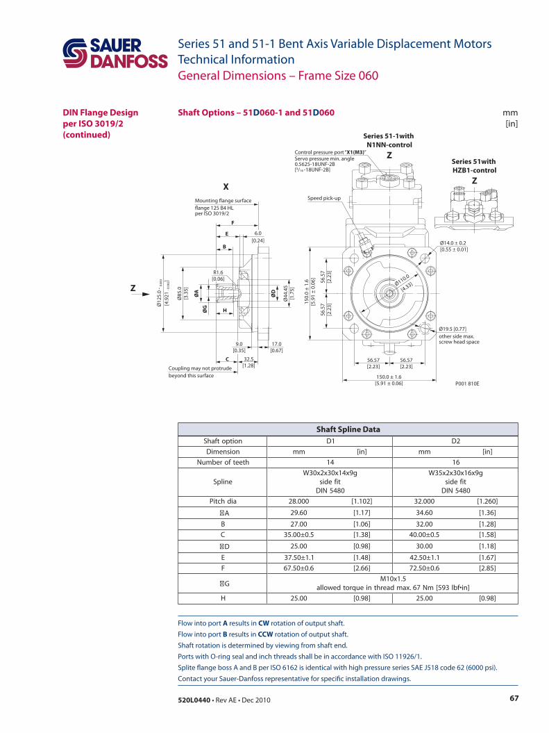
67520L0440 • Rev AE • Dec 2010
Series 51 and 51-1 Bent Axis Variable Displacement MotorsTechnical Information
Flow into port A results in CW rotation of output shaft. Flow into port B results in CCW rotation of output shaft. Shaft rotation is determined by viewing from shaft end. Ports with O-ring seal and inch threads shall be in accordance with ISO 11926/1. Splite flange boss A and B per ISO 6162 is identical with high pressure series SAE J518 code 62 (6000 psi). Contact your Sauer-Danfoss representative for specific installation drawings.
mm[in]
Shaft Options – 51D060-1 and 51D060
Ø12
5.0
- 0.0
63
[4.9
21 - 0
.002
]
Ø44
.45
[1.7
5]
ØG
ØA
Ø85
.0[3
.35]
ØD
H
F
E
B
C
17.0[0.67]
32.5[1.28]
9.0[0.35]
6.0[0.24]
P001 810E
56.5
7[2
.23]
56.57[2.23]
56.57[2.23]
56.5
7[2
.23]
150.
0 ±
1.6
[5.9
1 ±
0.06
]
150.0 ± 1.6[5.91 ± 0.06]
Ø110.0
[4.33]
R1.6[0.06]
Mounting ange surfaceange 125 B4 HLper ISO 3019/2
Coupling may not protrudebeyond this surface
Ø14.0 ± 0.2[0.55 ± 0.01]
Speed pick-up
Ø19.5 [0.77]other side max.screw head space
Control pressure port “X1(M3)”Servo pressure min. angle0.5625-18UNF-2B[9/16 -18UNF-2B]
X
Z
Series 51with HZB1-control
Z
Series 51-1with N1NN-control
Z
General Dimensions – Frame Size 060
DIN Flange Designper ISO 3019/2(continued)
noitpotfahS 1D 2D
noisnemiD mm ]ni[ mm ]ni[
hteetforebmuN 41 61
enilpSg9x41x03x2x03W
tifedis0845NID
g9x61x03x2x53Wtifedis0845NID
aidhctiP 000.82 ]201.1[ 000.23 ]062.1[
A 06.92 ]71.1[ 06.43 ]63.1[
B 00.72 ]60.1[ 00.23 ]82.1[
C 5.0±00.53 ]83.1[ 5.0±00.04 ]85.1[
D 00.52 ]89.0[ 00.03 ]81.1[
E 1.1±05.73 ]84.1[ 1.1±05.24 ]76.1[
F 6.0±05.76 ]66.2[ 6.0±05.27 ]58.2[
G5.1x01M
]ni•fbl395[mN76.xamdaerhtnieuqrotdewolla
H 00.52 ]89.0[ 00.52 ]89.0[
Shaft Spline Data
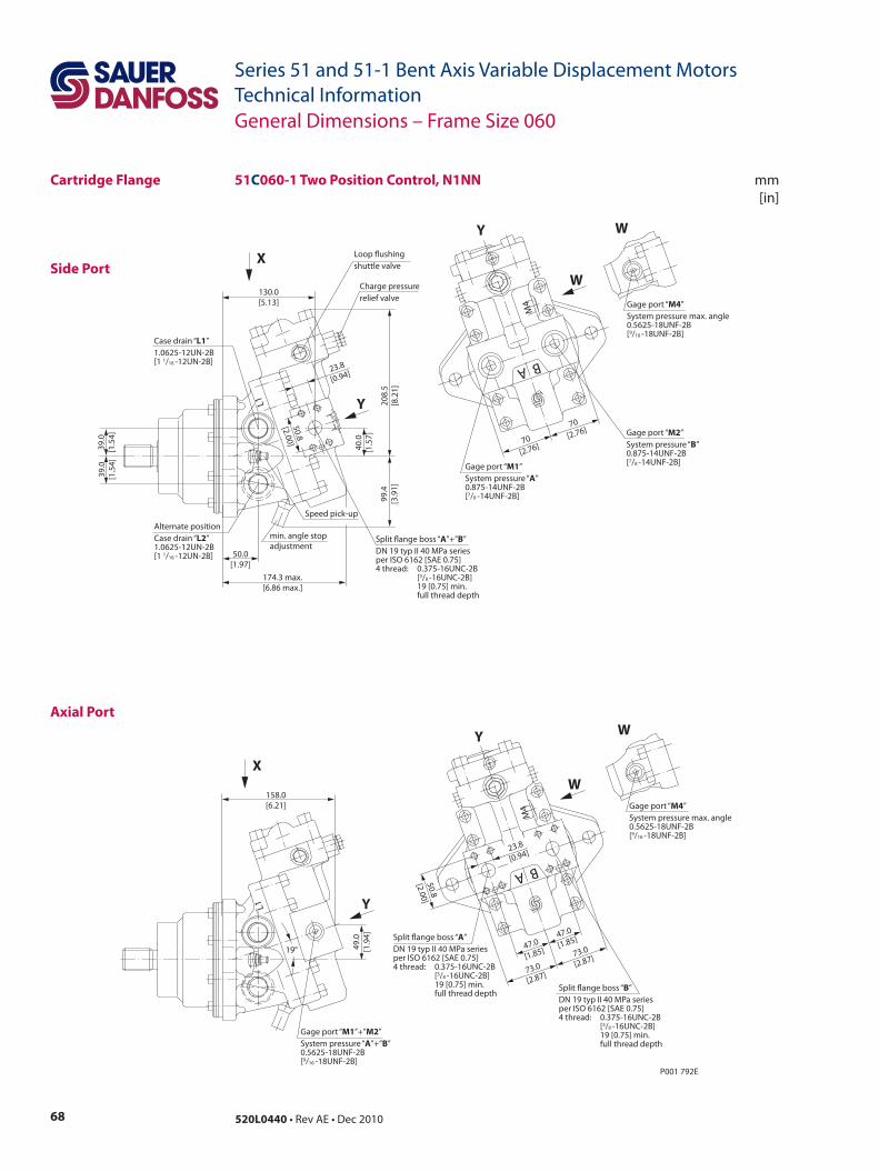
68 520L0440 • Rev AE • Dec 2010
Series 51 and 51-1 Bent Axis Variable Displacement MotorsTechnical Information
mm[in]
Side Port
Axial Port
51C060-1 Two Position Control, N1NN
70[2.76]
70[2.76]
A B
M4
50.0[1.97]
40.0
[1.5
7]
130.0[5.13]
174.3 max.[6.86 max.]
39.0
[1.5
4]39
.0[1
.54]
208.
5[8
.21]
99.4
[3.9
1]
50.8
[2.00]
23.8
[0.94]
L1
P001 792E
47.0
[1.85]
50.8
[2.00]
73.0
[2.87]
73.0
[2.87]
47.0
[1.85]
A B
M4
23.8
[0.94]
49.0
[1.9
4]
158.0[6.21]
L1
19°Split ange boss “A”DN 19 typ II 40 MPa seriesper ISO 6162 [SAE 0.75]4 thread: 0.375-16UNC-2B [3/8 -16UNC-2B] 19 [0.75] min. full thread depth
Split ange boss “B”DN 19 typ II 40 MPa seriesper ISO 6162 [SAE 0.75]4 thread: 0.375-16UNC-2B [3/8 -16UNC-2B] 19 [0.75] min. full thread depth
Gage port “M1”+”M2”System pressure “A”+”B”0.5625-18UNF-2B[9/16 -18UNF-2B]
W
Y
Gage port “M4”System pressure max. angle0.5625-18UNF-2B[9/16 -18UNF-2B]
W
Y
X
Gage port “M1”System pressure “A” 0.875-14UNF-2B[7/8 -14UNF-2B]
Gage port “M2”System pressure “B” 0.875-14UNF-2B[7/8 -14UNF-2B]
Loop ushingshuttle valve
Charge pressurerelief valve
min. angle stopadjustment
Split ange boss “A”+”B”DN 19 typ II 40 MPa seriesper ISO 6162 [SAE 0.75]4 thread: 0.375-16UNC-2B [3/8 -16UNC-2B] 19 [0.75] min. full thread depth
Case drain “L1”1.0625-12UN-2B[1 1/16 -12UN-2B]
Alternate positionCase drain “L2”1.0625-12UN-2B[1 1/16 -12UN-2B]
W
Y
Gage port “M4”System pressure max. angle0.5625-18UNF-2B[9/16 -18UNF-2B]
W
Y
X
Speed pick-up
General Dimensions – Frame Size 060
Cartridge Flange
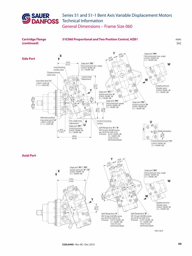
69520L0440 • Rev AE • Dec 2010
Series 51 and 51-1 Bent Axis Variable Displacement MotorsTechnical Information
mm[in]
Side Port
Axial Port
Cartridge Flange(continued)
51C060 Proportional and Two Position Control, HZB1
General Dimensions – Frame Size 060
N
L2
AL1
M3
M1
M5
45.0
[1.77]45.0
[1.77]
50.80
[2.00]
70.0
[2.76 ]70.0
[2.76 ]
23.80
[0.94]
Split ange boss “A”DN 19 typ II 40 MPa seriesper ISO 6162 [SAE 0.75]4 thread: 0.375-16UNC-2B [3/8 -16UNC-2B] 19 [0.75] min. full thread depth
Split ange boss “B”DN 19 typ II 40 MPa seriesper ISO 6162 [SAE 0.75]4 thread: 0.375-16UNC-2B [3/8 -16UNC-2B] 19 [0.75] min. full thread depth
Gage port “M1”+”M2”System pressure “A”+”B”0.5625-18UNF-2B[9/16 -18UNF-2B]
179.0[7.03]
P001 967E
56.0
[2.2
2]
Gage port “M1”System pressure “A” 0.5625-18UNF-2B[9/16 -18UNF-2B]
Gage port “M2”System pressure “B” 0.5625-18UNF-2B[9/16 -18UNF-2B]
66.0
[2.60]
66.0
[2.60]
50.0[1.97]
Control StartAdjustment
Gage port “M3”Servo pressure min. angle0.5625-18UNF-2B[9/16 -18UNF-2B]
Gage port “M5”Servo pressure supply0.5625-18UNF-2B[9/16 -18UNF-2B]
Control mountingsurface
209.0[8.24]
39.0
[1.5
4]39
.0[1
.54]
172.
0[6
.77]
96.0
[3.7
7]
41.0
[1.6
0]
132.0[5.21]
19°
Case drain port “L1”1.0625-12UN-2B[1 1/16 -12UN-2B]
50.80
[2.00]
23.90
[0.94]
Split ange boss “A”+”B”DN 19 typ II 40 MPa seriesper ISO 6162 [SAE 0.75]4 thread: 0.375-16UNC-2B [3/8 -16UNC-2B] 19 [0.75] min. full thread depth
Gage port “M7”Control pressure0.5625-18UNF-2B[9/16 -18UNF-2B]
99.0
[3.8
9]
min. angle stopadjustment
Charge pressurerelief valve
Alternate positionCase drain port “L2”1.0625-12UN-2B[1 1/16 -12UN-2B]
Loop Flushingshuttle valve
L2
N
L1
M3
BA
M5
M4
Y
Y
X
U
Y
Y
X
Shaft centerline
Control pressure port “X1”0.5625-18UNF-2B[9/16 -18UNF-2B]
U
X1
M7
49.0
[1.9
3]
Supply pressureShuttle valve0.5625-18UNF-2B[9/16 -18UNF-2B]
Gage port “M4”Servo pressure max. angle0.5625-18UNF-2B[9/16 -18UNF-2B]
W
W
M4
Supply pressureShuttle valve0.5625-18UNF-2B[9/16 -18UNF-2B]
Gage port “M4”Servo pressure max. angle0.5625-18UNF-2B[9/16 -18UNF-2B]
W
W
M4
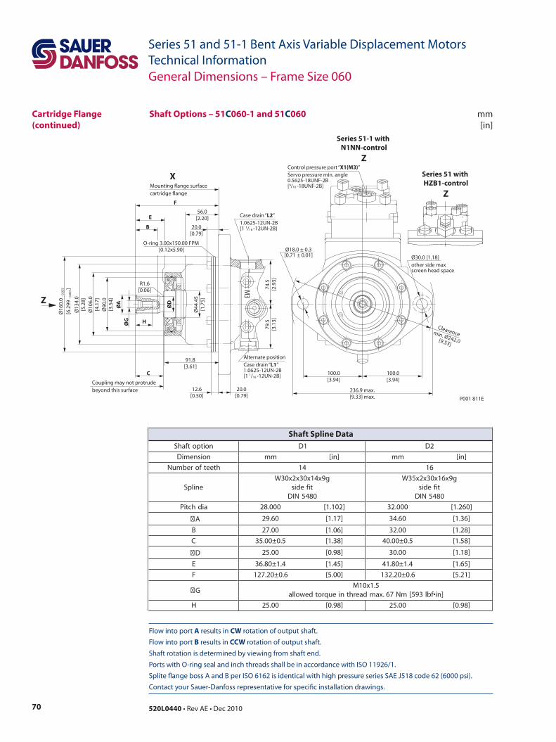
70 520L0440 • Rev AE • Dec 2010
Series 51 and 51-1 Bent Axis Variable Displacement MotorsTechnical Information
Flow into port A results in CW rotation of output shaft. Flow into port B results in CCW rotation of output shaft. Shaft rotation is determined by viewing from shaft end. Ports with O-ring seal and inch threads shall be in accordance with ISO 11926/1. Splite flange boss A and B per ISO 6162 is identical with high pressure series SAE J518 code 62 (6000 psi). Contact your Sauer-Danfoss representative for specific installation drawings.
mm[in]
Shaft Options – 51C060-1 and 51C060
P001 811E
100.0[3.94]
100.0[3.94]
Clearancemin. Ø242.0[9.53]
Ø18.0 ± 0.3[0.71 ± 0.01]
236.9 max.[9.33] max.
ØG
ØA
Ø90
.0[3
.54]
Ø10
6.0
[4.1
7]
Ø13
4.0
[5.2
8]
79.5
[3.1
3]74
.5[2
.93]
H
56.0[2.20]
B
E
F
C
12.6[0.50]
91.8[3.61]
20.0[0.79]
20.0[0.79]
ØD
Ø16
0.0
- 0.0
25
[6.2
99 - 0
.001
]
R1.6[0.06] M
3
Ø44
.45
[1.7
5]Z
XMounting ange surfacecartridge ange
Alternate positionCase drain “L1”1.0625-12UN-2B[1 1/16 -12UN-2B]
Coupling may not protrudebeyond this surface
Case drain “L2”1.0625-12UN-2B[1 1/16 -12UN-2B]
O-ring 3.00x150.00 FPM [0.12x5.90]
Ø30.0 [1.18]other side maxscreen head space
Control pressure port “X1(M3)”Servo pressure min. angle0.5625-18UNF-2B[9/16 -18UNF-2B]
Series 51 with HZB1-control
Z
Series 51-1 with N1NN-control
Z
General Dimensions – Frame Size 060
Cartridge Flange(continued)
noitpotfahS 1D 2D
noisnemiD mm ]ni[ mm ]ni[
hteetforebmuN 41 61
enilpSg9x41x03x2x03W
tifedis0845NID
g9x61x03x2x53Wtifedis0845NID
aidhctiP 000.82 ]201.1[ 000.23 ]062.1[
A 06.92 ]71.1[ 06.43 ]63.1[
B 00.72 ]60.1[ 00.23 ]82.1[
C 5.0±00.53 ]83.1[ 5.0±00.04 ]85.1[
D 00.52 ]89.0[ 00.03 ]81.1[
E 4.1±08.63 ]54.1[ 4.1±08.14 ]56.1[
F 6.0±02.721 ]00.5[ 6.0±02.231 ]12.5[
G5.1x01M
]ni•fbl395[mN76.xamdaerhtnieuqrotdewolla
H 00.52 ]89.0[ 00.52 ]89.0[
Shaft Spline Data
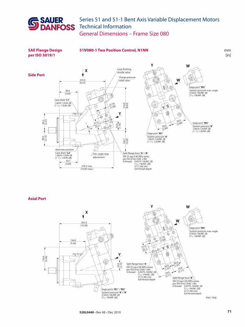
71520L0440 • Rev AE • Dec 2010
Series 51 and 51-1 Bent Axis Variable Displacement MotorsTechnical Information
mm[in]
Side Port
Axial Port
51V080-1 Two Position Control, N1NN
P001 793E
57.12
[2.25]
50.0
[1.97]
79.0
[3.11]
79.0
[3.11]
50.0
[1.97]
A B
M4
27.76
[1.09]
53.0
[2.1
0]
116.
0[4
.58]
261.0[10.28]
134.0[5.26]
93.7[3.69]
94.0[3.69]
45.0
[1.7
6]
19°
235.0[9.27]
278.2 max.[10.95 max.]
85.5
[3.3
7]80
.0[3
.15]
218.
9[8
.62]
106.
7[4
.20]
27.76
[1.09]
57.12
[2.25] 76.0
[2.99]
76.0
[2.99]
M4
A B
Y
X
W
Y
Gage port “M4”System pressure max. angle0.5625-18UNF-2B[9/16 -18UNF-2B]
WLoop ushingshuttle valve
Charge pressurerelief valve
min. angle stopadjustment
Split ange boss “A”+”B”DN 25 typ II 40 MPa seriesper ISO 6162 [SAE 1.00]4 thread: 0.4375-14UNC-2B [7/16 -14UNC-2B] 27 [1.06] min. full thread depth
Case drain “L1”1.0625-12UN-2B[1 1/16 -12UN-2B]
Alternate positionCase drain “L2”1.0625-12UN-2B[1 1/16 -12UN-2B]
Gage port “M1”System pressure “A” 1.0625-12UNF-2B[1 1/16 -12UNF-2B]
Gage port “M2”System pressure “B” 1.0625-12UNF-2B[1 1/16 -12UNF-2B]
Y
X
W
Y
Gage port “M4”System pressure max. angle0.5625-18UNF-2B[9/16 -18UNF-2B]
W
Gage ports “M1”+”M2”System pressure “A”+”B” 0.5625-18UNF-2B[9/16 -18UNF-2B]
Split ange boss “A”DN 25 typ II 40 MPa seriesper ISO 6162 [SAE 1.00]4 thread: 0.4375-14UNC-2B [7/16 -14UNC-2B] 27 [1.06] min. full thread depth
Split ange boss “B”DN 25 typ II 40 MPa seriesper ISO 6162 [SAE 1.00]4 thread: 0.4375-14UNC-2B [7/16 -14UNC-2B] 27 [1.06] min. full thread depth
General Dimensions – Frame Size 080
SAE Flange Designper ISO 3019/1
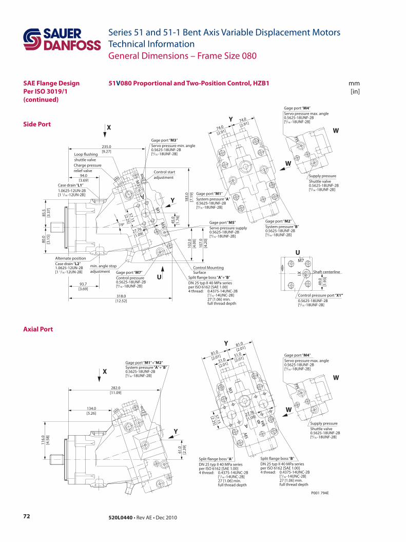
72 520L0440 • Rev AE • Dec 2010
Series 51 and 51-1 Bent Axis Variable Displacement MotorsTechnical Information
mm[in]
Side Port
Axial Port
P001 794E
51.0
[2.01]
51.0
[2.01]
57.15
[2.25]
81.0
[2.01]
81.0
[2.01]
M3
M5
BA M
4
27.76
[1.09]
Split ange boss “A”DN 25 typ II 40 MPa seriesper ISO 6162 [SAE 1.00]4 thread: 0.4375-14UNC-2B [7/16 -14UNC-2B] 27 [1.06] min. full thread depth
Split ange boss “B”DN 25 typ II 40 MPa seriesper ISO 6162 [SAE 1.00]4 thread: 0.4375-14UNC-2B [7/16 -14UNC-2B] 27 [1.06] min. full thread depth
Gage port “M1”+”M2”System pressure “A”+”B”0.5625-18UNF-2B[9/16 -18UNF-2B]
282.0[11.09]
61.0
[2.3
9]
116.
0[4
.58]
134.0[5.26]
Gage port “M2”System pressure “B” 0.5625-18UNF-2B[9/16 -18UNF-2B]
Gage port “M1”System pressure “A” 0.5625-18UNF-2B[9/16 -18UNF-2B]
74.0
[2.91]
74.0
[2.91]
93.7[3.69]
94.0[3.69]
Control startadjustment
Gage port “M3”Servo pressure min. angle0.5625-18UNF-2B[9/16 -18UNF-2B]
Gage port “M5”Servo pressure supply0.5625-18UNF-2B[9/16 -18UNF-2B]
Control MountingSurface
Loop ushingshuttle valve
318.0[12.52]
85.5
[3.3
7]80
.0[3
.15]
183.
0[7
.19]
102.
0[4
.00]
M1
M5
M3
A
45.0
[1.7
6]
235.0[9.27]
Alternate positionCase drain “L2”1.0625-12UN-2B[1 1/16 -12UN-2B]
19°
Case drain “L1”1.0625-12UN-2B[1 1/16 -12UN-2B]
Split ange boss “A”+”B”DN 25 typ II 40 MPa seriesper ISO 6162 [SAE 1.00]4 thread: 0.4375-14UNC-2B [7/16 -14UNC-2B] 27 [1.06] min. full thread depth
Gage port “M7”Control pressure0.5625-18UNF-2B[9/16 -18UNF-2B]
107.
0[4
.20]
min. angle stopadjustment
Charge pressurerelief valve
Y
Y
X
U
Y
Y
X
Shaft centerline
Control pressure port “X1”0.5625-18UNF-2B[9/16 -18UNF-2B]
U
X1
M7
49.0
[1.9
3]
Supply pressureShuttle valve0.5625-18UNF-2B[9/16 -18UNF-2B]
Gage port “M4”Servo pressure max. angle0.5625-18UNF-2B[9/16 -18UNF-2B]
W
W
M4
Supply pressureShuttle valve0.5625-18UNF-2B[9/16 -18UNF-2B]
Gage port “M4”Servo pressure max. angle0.5625-18UNF-2B[9/16 -18UNF-2B]
W
W
M4
27.76
[1.09]
57.15
[2.25]
51V080 Proportional and Two-Position Control, HZB1
General Dimensions – Frame Size 080
SAE Flange DesignPer ISO 3019/1(continued)
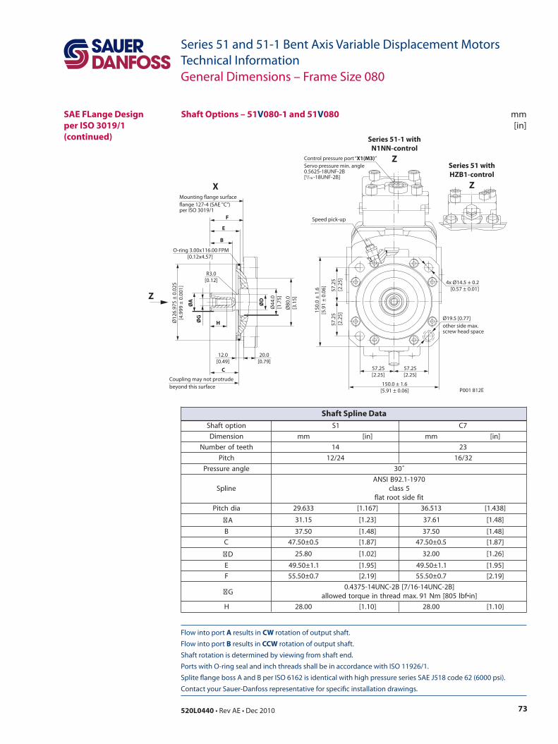
73520L0440 • Rev AE • Dec 2010
Series 51 and 51-1 Bent Axis Variable Displacement MotorsTechnical Information
Flow into port A results in CW rotation of output shaft. Flow into port B results in CCW rotation of output shaft. Shaft rotation is determined by viewing from shaft end. Ports with O-ring seal and inch threads shall be in accordance with ISO 11926/1. Splite flange boss A and B per ISO 6162 is identical with high pressure series SAE J518 code 62 (6000 psi). Contact your Sauer-Danfoss representative for specific installation drawings.
mm[in]
Ø12
6.97
5 ±
0.02
5[4
.999
± 0
.001
]
Ø80
.0[3
.15]
Ø44
.0[1
.75]
ØG
ØA ØD
H
F
E
B
57.2
5 [2
.25]
57.2
5 [2
.25]
57.25[2.25]
150.0 ± 1.6[5.91 ± 0.06]
150.
0 ±
1.6
[5.9
1 ±
0.06
]
57.25[2.25]
P001 812E
C
12.0[0.49]
20.0[0.79]
R3.0[0.12]
Coupling may not protrudebeyond this surface
Mounting ange surfaceange 127-4 (SAE "C")per ISO 3019/1
O-ring 3.00x116.00 FPM [0.12x4.57]
Ø19.5 [0.77]other side max.screw head space
4x Ø14.5 ± 0.2[0.57 ± 0.01]
Speed pick-up
Control pressure port “X1(M3)”Servo pressure min. angle0.5625-18UNF-2B[9/16 -18UNF-2B]
X
Z
Series 51 withHZB1-control
Z
Series 51-1 withN1NN-control
Z
General Dimensions – Frame Size 080
SAE FLange Design per ISO 3019/1(continued)
Shaft Options – 51V080-1 and 51V080
noitpotfahS 1S 7C
noisnemiD mm ]ni[ mm ]ni[
hteetforebmuN 41 32
hctiP 42/21 23/61
elgnaerusserP ˚03
enilpS0791-1.29BISNA
5ssalctifedistoortalf
aidhctiP 336.92 ]761.1[ 315.63 ]834.1[
A 51.13 ]32.1[ 16.73 ]84.1[
B 05.73 ]84.1[ 05.73 ]84.1[
C 5.0±05.74 ]78.1[ 5.0±05.74 ]78.1[
D 08.52 ]20.1[ 00.23 ]62.1[
E 1.1±05.94 ]59.1[ 1.1±05.94 ]59.1[
F 7.0±05.55 ]91.2[ 7.0±05.55 ]91.2[
G]B2-CNU41-61/7[B2-CNU41-5734.0
]ni•fbl508[mN19.xamdaerhtnieuqrotdewolla
H 00.82 ]01.1[ 00.82 ]01.1[
Shaft Spline Data
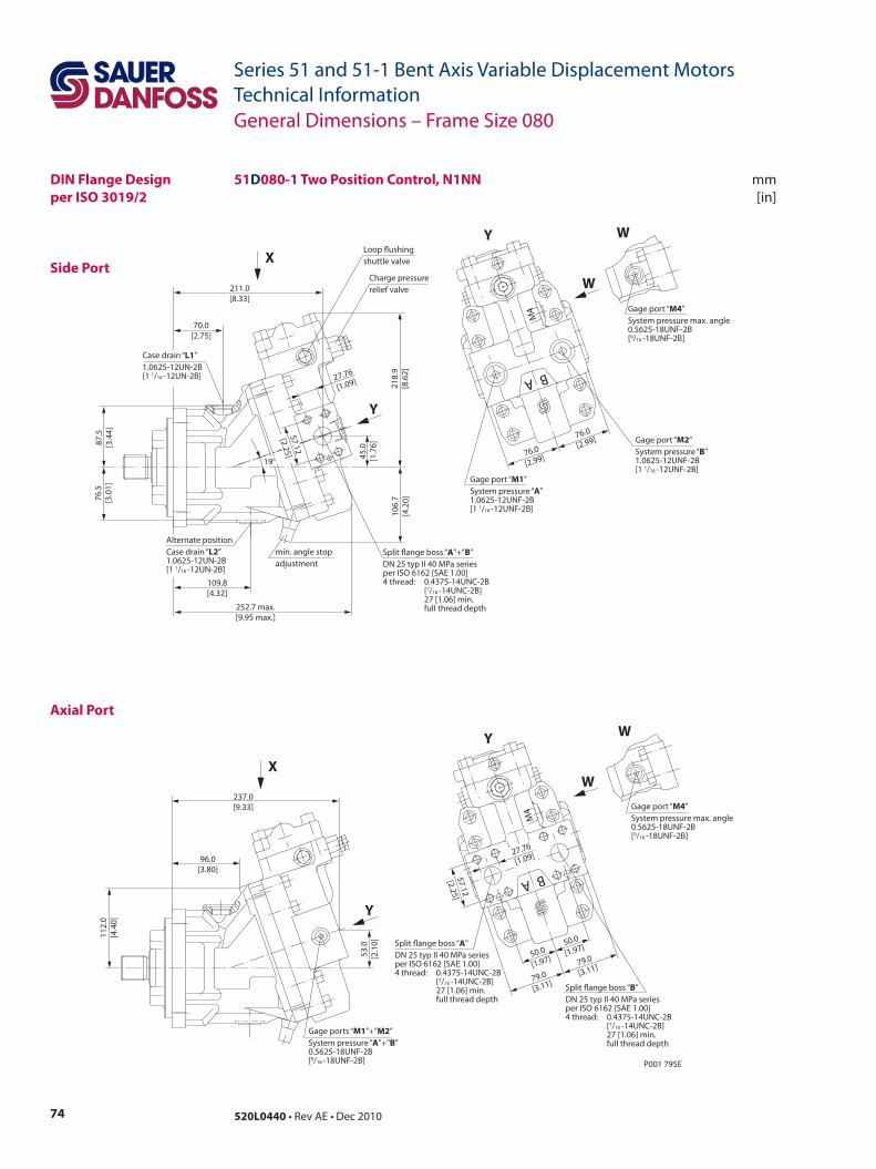
74 520L0440 • Rev AE • Dec 2010
Series 51 and 51-1 Bent Axis Variable Displacement MotorsTechnical Information
mm[in]
Side Port
Axial Port
P001 795E
57.12
[2.25]
50.0
[1.97]
79.0
[3.11]
79.0
[3.11]
50.0
[1.97]
A B
M4
27.76
[1.09]
53.0
[2.1
0]
112.
0[4
.40]
237.0[9.33]
96.0[3.80]
76.0
[2.99]
76.0
[2.99]
A B
M4
109.8[4.32]
70.0[2.75]
45.0
[1.7
6]
19°
211.0[8.33]
252.7 max.[9.95 max.]
87.5
[3.4
4]76
.5[3
.01]
218.
9[8
.62]
106.
7[4
.20]
27.76
[1.09]
57.12
[2.25]
Loop ushingshuttle valve
Charge pressurerelief valve
min. angle stopadjustment
Split ange boss “A”+”B”DN 25 typ II 40 MPa seriesper ISO 6162 [SAE 1.00]4 thread: 0.4375-14UNC-2B [7/16 -14UNC-2B] 27 [1.06] min. full thread depth
Case drain “L1”1.0625-12UN-2B[1 1/16 -12UN-2B]
Alternate positionCase drain “L2”1.0625-12UN-2B[1 1/16 -12UN-2B]
Y
X
W
Y
Gage port “M4”System pressure max. angle0.5625-18UNF-2B[9/16 -18UNF-2B]
W
Gage port “M1”System pressure “A” 1.0625-12UNF-2B[1 1/16 -12UNF-2B]
Gage port “M2”System pressure “B” 1.0625-12UNF-2B[1 1/16 -12UNF-2B]
Y
XW
Y
Gage port “M4”System pressure max. angle0.5625-18UNF-2B[9/16 -18UNF-2B]
W
Gage ports “M1”+”M2”System pressure “A”+”B” 0.5625-18UNF-2B[9/16 -18UNF-2B]
Split ange boss “A”DN 25 typ II 40 MPa seriesper ISO 6162 [SAE 1.00]4 thread: 0.4375-14UNC-2B [7/16 -14UNC-2B] 27 [1.06] min. full thread depth
Split ange boss “B”DN 25 typ II 40 MPa seriesper ISO 6162 [SAE 1.00]4 thread: 0.4375-14UNC-2B [7/16 -14UNC-2B] 27 [1.06] min. full thread depth
General Dimensions – Frame Size 080
DIN Flange Designper ISO 3019/2
51D080-1 Two Position Control, N1NN
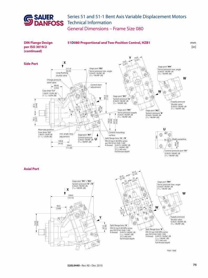
75520L0440 • Rev AE • Dec 2010
Series 51 and 51-1 Bent Axis Variable Displacement MotorsTechnical Information
mm[in]
Side Port
Axial Port
DIN Flange Designper ISO 3019/2(continued)
51D080 Proportional and Two-Position Control, HZB1
P001 796E
109.8[4.32]
66.65[2.62]
Control startadjustment
Gage port “M3”Servo pressure min. angle0.5625-18UNF-2B[9/16 -18UNF-2B]
Gage port “M5”Servo pressure supply0.5625-18UNF-2B[9/16 -18UNF-2B]
Control mountingsurface
Loop ushingshuttle valve
294.0[11.58]
87.5
[3.4
4]76
.5[3
.01]
183.
0[7
.19]
102.
0[4
.00]
M1
M5
M3
A
45.0
[1.7
6]
211.0[8.33]
Alternate positionCase drain “L2”1.0625-12UN-2B[1 1/16 -12UN-2B]
19°
Case drain “L1”1.0625-12UN-2B[1 1/16 -12UN-2B]
min. angle stopadjustment
Gage port “M7”Control pressure0.5625-18UNF-2B[9/16 -18UNF-2B]
107.
0 [4
.20]
27.76
[1.09]
57.15
[2.25]
Charge pressurerelief valve
Split ange boss “A”+”B”DN 25 typ II 40 MPa seriesper ISO 6162 [SAE 1.00]4 thread: 0.4375-14UNC-2B [7/16 -14UNC-2B] 27 [1.06] min. full thread depth
Gage port “M2”System pressure “B” 0.5625-18UNF-2B[9/16 -18UNF-2B]
Gage port “M1”System pressure “A” 0.5625-18UNF-2B[9/16 -18UNF-2B]
74.0
[2.91]
74.0
[2.91]
51[2.01]
57.15
[2.25]
81.0
[3.19]
81.0
[3.19]
51[2.01]
M3
BA M
4
M5
27.76
[1.09]
Split ange boss “A”DN 25 typ II 40 MPa seriesper ISO 6162 [SAE 1.00]4 thread: 0.4375-14UNC-2B [7/16 -14UNC-2B] 27 [1.06] min. full thread depth
Split ange boss “B”DN 25 typ II 40 MPa seriesper ISO 6162 [SAE 1.00]4 thread: 0.4375-14UNC-2B [7/16 -14UNC-2B] 27 [1.06] min. full thread depth
Gage port “M1”+”M2”System pressure “A”+”B”0.5625-18UNF-2B[9/16 -18UNF-2B]
258.0[10.15]
61.0
[2.3
9]112.
0[4
.40]
96.0[3.80]
Y
Y
X
U
Y
X
W
Shaft centerline
Control pressure port “X1”0.5625-18UNF-2B[9/16 -18UNF-2B]
U
X1
M7
49.0
[1.9
3]
Supply pressureShuttle valve0.5625-18UNF-2B[9/16 -18UNF-2B]
Gage port “M4”Servo pressure max. angle0.5625-18UNF-2B[9/16 -18UNF-2B]
W
M4
Supply pressureShuttle valve0.5625-18UNF-2B[9/16 -18UNF-2B]
Gage port “M4”Servo pressure max. angle0.5625-18UNF-2B[9/16 -18UNF-2B]
W
W
M4
General Dimensions – Frame Size 080
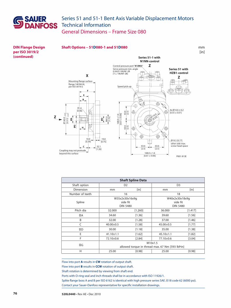
76 520L0440 • Rev AE • Dec 2010
Series 51 and 51-1 Bent Axis Variable Displacement MotorsTechnical Information
Flow into port A results in CW rotation of output shaft. Flow into port B results in CCW rotation of output shaft. Shaft rotation is determined by viewing from shaft end. Ports with O-ring seal and inch threads shall be in accordance with ISO 11926/1. Splite flange boss A and B per ISO 6162 is identical with high pressure series SAE J518 code 62 (6000 psi). Contact your Sauer-Danfoss representative for specific installation drawings.
mm[in]
P001 813E
45.
0[1
.75]
ØG
ØA
ØD
H
F
E
B
C
Ø14
0.0
- 0.0
63
[5.5
12 - 0
.002
]
19.0[0.75]
32.1[1.26]
10.0[0.39]
R1.6[0.06]
Ø110.0
[4.33]
63.6[2.5]
63.6[2.5]
168.0 ± 1.6[6.61 ± 0.06]
63.6
[2.5
]63
.6[2
.5]
168.
0 ±
1.6
[6.6
1 ±
0.0
6]
Mounting flange surfaceflange 140 B4 HLper ISO 3019/2
Coupling may not protrudebeyond this surface
4x Ø14.0 ± 0.2[0.55 ± 0.01]
Speed pick-up
Ø19.5 [0.77]other side max.screw head space
Control pressure port “X1(M3)”Servo pressure min. angle0.5625-18UNF-2B[9/16 -18UNF-2B]
X
Z
Series 51-1 with N1NN-control
ZSeries 51 with HZB1-control
Z
General Dimensions – Frame Size 080
DIN Flange Designper ISO 3019/2(continued)
Shaft Options – 51D080-1 and 51D080
noitpotfahS 2D 3D
noisnemiD mm ]ni[ mm ]ni[
hteetforebmuN 61 81
enilpSg9x61x03x2x53W
tifedis0845NID
g9x81x03x2x04Wtifedis0845NID
aidhctiP 000.23 ]062.1[ 000.63 ]714.1[
A 06.43 ]63.1[ 06.93 ]65.1[
B 00.23 ]82.1[ 00.73 ]64.1[
C 5.0±00.04 ]85.1[ 5.0±00.54 ]77.1[
D 00.03 ]81.1[ 00.53 ]83.1[
E 1.1±01.14 ]26.1[ 1.1±01.54 ]28.1[
F 6.0±01.27 ]48.2[ 6.0±01.77 ]40.3[
G5.1x01M
]ni•fbl395[mN76.xamdaerhtnieuqrotdewolla
H 00.52 ]89.0[ 00.52 ]89.0[
Shaft Spline Data
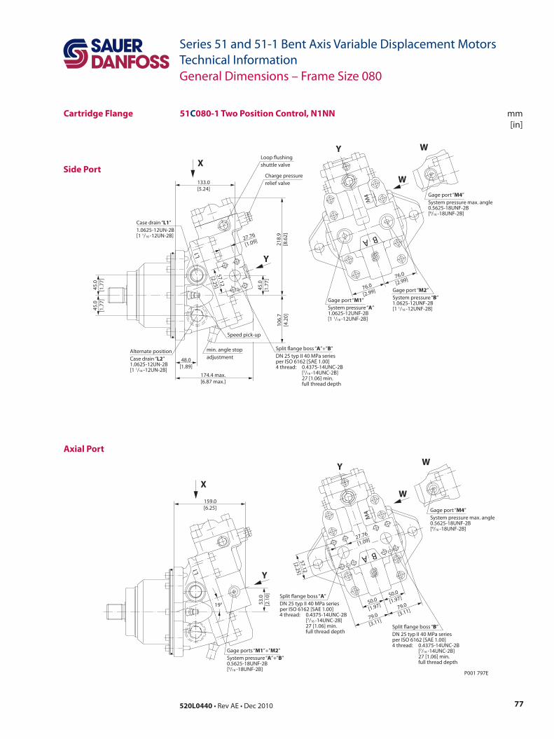
77520L0440 • Rev AE • Dec 2010
Series 51 and 51-1 Bent Axis Variable Displacement MotorsTechnical Information
mm[in]
Side Port
Axial Port
51C080-1 Two Position Control, N1NN
P001 797E
76.0
[2.99]
76.0
[2.99]
A B
M4
L1
48.0[1.89]
45.0
[1.7
7]
133.0[5.24]
174.4 max.[6.87 max.]
45.0
[1.7
7]45
.0[1
.77]
218.
9[8
.62]
106.
7[4
.20]
27.76
[1.09]
57.12
[2.25]
57.12
[2.25]
50.0
[1.97]
79.0
[3.11]
79.0
[3.11]
50.0
[1.97]
A B
M4
27.76
[1.09]
53.0
[2.1
0]
159.0[6.25]
L1
19°
Y
X
W
Y
Gage port “M4”System pressure max. angle0.5625-18UNF-2B[9/16 -18UNF-2B]
W
Y
XW
Y
Gage port “M4”System pressure max. angle0.5625-18UNF-2B[9/16 -18UNF-2B]
W
Loop ushingshuttle valve
Charge pressurerelief valve
min. angle stopadjustment
Split ange boss “A”+”B”DN 25 typ II 40 MPa seriesper ISO 6162 [SAE 1.00]4 thread: 0.4375-14UNC-2B [7/16 -14UNC-2B] 27 [1.06] min. full thread depth
Case drain “L1”1.0625-12UN-2B[1 1/16 -12UN-2B]
Alternate positionCase drain “L2”1.0625-12UN-2B[1 1/16 -12UN-2B]
Gage port “M1”System pressure “A” 1.0625-12UNF-2B[1 1/16 -12UNF-2B]
Gage port “M2”System pressure “B” 1.0625-12UNF-2B[1 1/16 -12UNF-2B]
Speed pick-up
Gage ports “M1”+”M2”System pressure “A”+”B” 0.5625-18UNF-2B[9/16 -18UNF-2B]
Split ange boss “A”DN 25 typ II 40 MPa seriesper ISO 6162 [SAE 1.00]4 thread: 0.4375-14UNC-2B [7/16 -14UNC-2B] 27 [1.06] min. full thread depth
Split ange boss “B”DN 25 typ II 40 MPa seriesper ISO 6162 [SAE 1.00]4 thread: 0.4375-14UNC-2B [7/16 -14UNC-2B] 27 [1.06] min. full thread depth
General Dimensions – Frame Size 080
Cartridge Flange
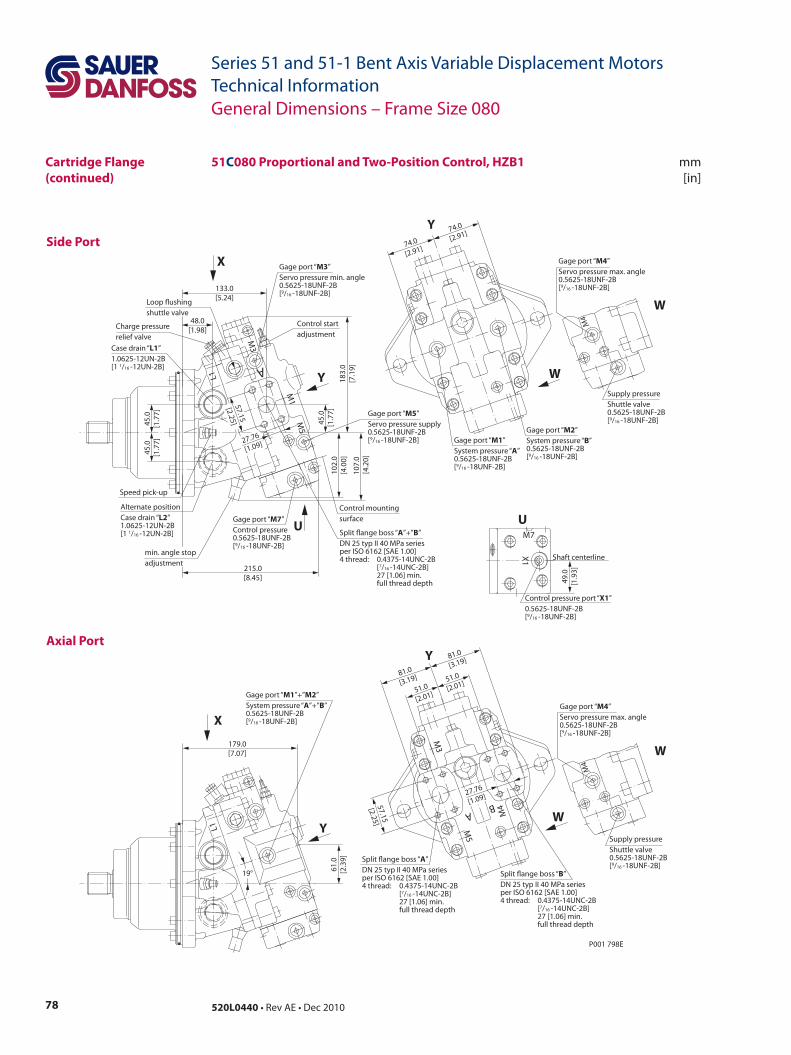
78 520L0440 • Rev AE • Dec 2010
Series 51 and 51-1 Bent Axis Variable Displacement MotorsTechnical Information
Side Port
mm[in]
Axial Port
P001 798E
57.15
[2.25]
51.0
[2.01]51.0
[2.01]
81.0
[3.19]
81.0
[3.19]
M4
M5
BA
M3
27.76
[1.09]
Split ange boss “A”DN 25 typ II 40 MPa seriesper ISO 6162 [SAE 1.00]4 thread: 0.4375-14UNC-2B [7/16 -14UNC-2B] 27 [1.06] min. full thread depth
Split ange boss “B”DN 25 typ II 40 MPa seriesper ISO 6162 [SAE 1.00]4 thread: 0.4375-14UNC-2B [7/16 -14UNC-2B] 27 [1.06] min. full thread depth
Gage port “M1”+”M2”System pressure “A”+”B”0.5625-18UNF-2B[9/16 -18UNF-2B]
179.0[7.07]
61.0
[2.3
9]
L1
19°
48.0[1.98]
Control startadjustment
Gage port “M3”Servo pressure min. angle0.5625-18UNF-2B[9/16 -18UNF-2B]
Gage port “M5”Servo pressure supply0.5625-18UNF-2B[9/16 -18UNF-2B]
Control mountingsurface
Speed pick-up
215.0[8.45]
183.
0[7
.19]
102.
0[4
.00]
M1
M5
M3
A
45.0
[1.7
7]
133.0[5.24]
Alternate positionCase drain “L2”1.0625-12UN-2B[1 1/16 -12UN-2B]
Case drain “L1”1.0625-12UN-2B[1 1/16 -12UN-2B]
Gage port “M7”Control pressure0.5625-18UNF-2B[9/16 -18UNF-2B]
107.
0 [4
.20]
Charge pressurerelief valve
45.0
[1.7
7]45
.0[1
.77]
L1
57.15
[2.25]
27.76
[1.09]
Loop ushingshuttle valve
Split ange boss “A”+”B”DN 25 typ II 40 MPa seriesper ISO 6162 [SAE 1.00]4 thread: 0.4375-14UNC-2B [7/16 -14UNC-2B] 27 [1.06] min. full thread depth
min. angle stopadjustment
Gage port “M2”System pressure “B” 0.5625-18UNF-2B[9/16 -18UNF-2B]
Gage port “M1”System pressure “A” 0.5625-18UNF-2B[9/16 -18UNF-2B]
74.0
[2.91]
74.0
[2.91]
Shaft centerline
Control pressure port “X1”0.5625-18UNF-2B[9/16 -18UNF-2B]
U
X1
M7
49.0
[1.9
3]
Supply pressureShuttle valve0.5625-18UNF-2B[9/16 -18UNF-2B]
Gage port “M4”Servo pressure max. angle0.5625-18UNF-2B[9/16 -18UNF-2B]
W
W
M4
Supply pressureShuttle valve0.5625-18UNF-2B[9/16 -18UNF-2B]
Gage port “M4” Servo pressure max. angle 0.5625-18UNF-2B[9/16 -18UNF-2B]
W
W
M4
Y
X
Y
U
Y
Y
X
51C080 Proportional and Two-Position Control, HZB1
General Dimensions – Frame Size 080
Cartridge Flange(continued)
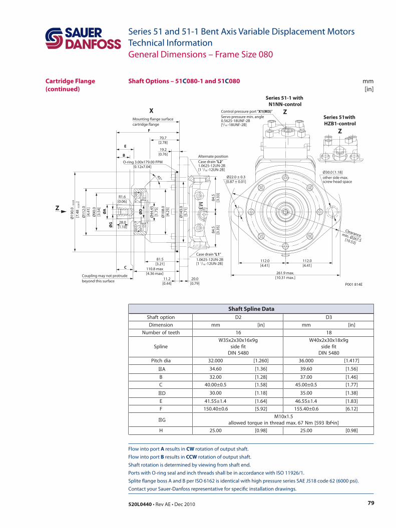
79520L0440 • Rev AE • Dec 2010
Series 51 and 51-1 Bent Axis Variable Displacement MotorsTechnical Information
Flow into port A results in CW rotation of output shaft. Flow into port B results in CCW rotation of output shaft. Shaft rotation is determined by viewing from shaft end. Ports with O-ring seal and inch threads shall be in accordance with ISO 11926/1. Splite flange boss A and B per ISO 6162 is identical with high pressure series SAE J518 code 62 (6000 psi). Contact your Sauer-Danfoss representative for specific installation drawings.
mm[in]
Shaft Options – 51C080-1 and 51C080
General Dimensions – Frame Size 080
Cartridge Flange(continued)
noitpotfahS 2D 3D
noisnemiD mm ]ni[ mm ]ni[
hteetforebmuN 61 81
enilpSg9x61x03x2x53W
tifedis0845NID
g9x81x03x2x04Wtifedis0845NID
aidhctiP 000.23 ]062.1[ 000.63 ]714.1[
A 06.43 ]63.1[ 06.93 ]65.1[
B 00.23 ]82.1[ 00.73 ]64.1[
C 5.0±00.04 ]85.1[ 5.0±00.54 ]77.1[
D 00.03 ]81.1[ 00.53 ]83.1[
E 4.1±55.14 ]46.1[ 4.1±55.64 ]38.1[
F 6.0±04.051 ]29.5[ 6.0±04.551 ]21.6[
G5.1x01M
]ni•fbl395[mN76.xamdaerhtnieuqrotdewolla
H 00.52 ]89.0[ 00.52 ]89.0[
Shaft Spline Data
P001 814E
112.0[4.41]
112.0[4.41]
Ø22.0 ± 0.3[0.87 ± 0.01]
261.9 max.[10.31 max.]
Ø30.0 [1.18]other side max.screw head space
ØG
ØA
Ø90
.0[3
.54]
Ø11
2.0
[4.4
1]
84.5
[3.3
3]84
.5[3
.35]
28.0[1.10]
B
45°
E
70.7[2.78]
F
C
Coupling may not protrudebeyond this surface 11.2
[0.44]
81.5[3.21]
110.8 max[4.36 max]
20.0[0.79]
Ø19
0.0
- 0.0
29
[7.4
8 - 0
.001
]
R1.6[0.06] M
3
ØD
Ø44
.45
[1.7
5]
Ø10
8.0
[4.2
5]
19.2[0.76]
Clearancemin. Ø267.5[10.53]
O-ring 3.00x179.00 FPM [0.12x7.04]
Mounting ange surfacecartridge ange
Ø14
3.0
[5.7
1]Z
X
Alternate positionCase drain “L2”1.0625-12UN-2B[1 1/16 -12UN-2B]
Case drain “L1”1.0625-12UN-2B[1 1/16 -12UN-2B]
Control pressure port “X1(M3)”Servo pressure min. angle0.5625-18UNF-2B[9/16 -18UNF-2B]
Series 51-1 with N1NN-control
ZSeries 51with HZB1-control
Z
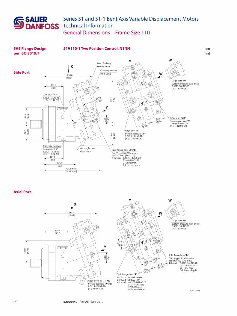
80 520L0440 • Rev AE • Dec 2010
Series 51 and 51-1 Bent Axis Variable Displacement MotorsTechnical Information
mm[in]
Side Port
Axial Port
51V110-1 Two Position Control, N1NN
P001 799E
57.12
[2.25]
50.0
[1.97]
80.0
[3.15]
80.0
[3.15]
50.0
[1.97]
A B
M4
27.76
[1.09]
58.0
[2.2
7]
121.
0[4
.74]
281.0[11.05]
134.0[5.27]
77.0
[3.03]77.0
[3.03]
A B
M4
101.0[3.98]
101.0[3.98]
48.0
[1.9
1]
19°
254.0[10.01]
301.2 max.[11.82 max.]
143.0[5.63]
87.0
[3.4
3]90
.0[3
.54]
232.
6[9
.16]
115.
0[4
.53]
27.76
[1.09]
57.12
[2.25]
Gage ports “M1”+”M2”System pressure “A”+”B” 0.5625-18UNF-2B[9/16 -18UNF-2B]
Split ange boss “A”DN 25 typ II 40 MPa seriesper ISO 6162 [SAE 1.00]4 thread: 0.4375-14UNC-2B [7/16 -14UNC-2B] 27 [1.06] min. full thread depth
Split ange boss “B”DN 25 typ II 40 MPa seriesper ISO 6162 [SAE 1.00]4 thread: 0.4375-14UNC-2B [7/16 -14UNC-2B] 27 [1.06] min. full thread depth
Y
X
W
Y
Gage port “M4”System pressure max. angle0.5625-18UNF-2B[9/16 -18UNF-2B]
W
Loop ushingshuttle valve
Charge pressurerelief valve
min. angle stopadjustment
Split ange boss “A”+”B”DN 25 typ II 40 MPa seriesper ISO 6162 [SAE 1.00]4 thread: 0.4375-14UNC-2B [7/16 -14UNC-2B] 27 [1.06] min. full thread depth
Case drain “L1”1.0625-12UN-2B[1 1/16 -12UN-2B]
Alternate positionCase drain “L2”1.0625-12UN-2B[1 1/16 -12UN-2B]
Gage port “M1”System pressure “A” 1.0625-12UNF-2B[1 1/16 -12UNF-2B]
Gage port “M2”System pressure “B” 1.0625-12UNF-2B[1 1/16 -12UNF-2B]
Y
XY
W
Gage port “M4”System pressure max. angle0.5625-18UNF-2B[9/16 -18UNF-2B]
W
General Dimensions – Frame Size 110
SAE Flange Designper ISO 3019/1
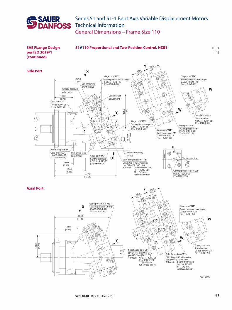
81520L0440 • Rev AE • Dec 2010
Series 51 and 51-1 Bent Axis Variable Displacement MotorsTechnical Information
mm[in]
Side Port
Axial Port
51V110 Proportional and Two-Position Control, HZB1
P001 800E
50.0
[1.97]
57.15
[2.25]
80.0
[3.15]
80.0
[3.15]
50.0
[1.97]
M3
M5
M4
A B
27.76
[1.09]
Split ange boss “A”DN 25 typ II 40 MPa seriesper ISO 6162 [SAE 1.00]4 thread: 0.4375-14UNC-2B [7/16 -14UNC-2B] 27 [1.06] min. full thread depth
Split ange boss “B”DN 25 typ II 40 MPa seriesper ISO 6162 [SAE 1.00]4 thread: 0.4375-14UNC-2B [7/16 -14UNC-2B] 27 [1.06] min. full thread depth
Gage port “M1”System pressure “A” 0.5625-18UNF-2B[9/16 -18UNF-2B]
Gage port “M2”System pressure “B” 0.5625-18UNF-2B[9/16 -18UNF-2B]
77.0
[3.03]
77.0
[3.03]
Gage port “M1”+”M2”System pressure “A”+”B”0.5625-18UNF-2B[9/16 -18UNF-2B]
300.0[11.8]
64.0
[2.5
3]
121.
0[4
.74]
134.0[5.27]
101.0[3.98]
101.0[3.98]
Control startadjustment
Gage port “M3”Servo pressure min. angle0.5625-18UNF-2B[9/16 -18UNF-2B]
Gage port “M5”Servo pressure supply0.5625-18UNF-2B[9/16 -18UNF-2B]
Control mountingsurface
Loop ushingshuttle valve
Charge pressurerelief valve
337.0[13.25]
143.0[5.63]
90.0
[3.5
4]87
.0[3
.43]
185.
0[7
.30]
103.
0[4
.00]
49.0
[1.9
1]
254.0[10.01]
Alternate positionCase drain “L2”1.0625-12UN-2B[1 1/16 -12UN-2B]
19°
Case drain “L”1.0625-12UN-2B[1 1/16 -12UN-2B]
Gage port “M7”Control pressure0.5625-18UNF-2B[9/16 -18UNF-2B]
115
max
.[4
.53]
max
.
A
M1
M5
M3
Split ange boss “A”+”B”DN 25 typ II 40 MPa seriesper ISO 6162 [SAE 1.00]4 thread: 0.4375-14UNC-2B [7/16 -14UNC-2B] 27 [1.06] min. full thread depth
min. angle stopadjustment
Shaft centerline
Control pressure port “X1”0.5625-18UNF-2B[9/16 -18UNF-2B]
U
X1
M7
49.0
[1.9
3]
Supply pressureShuttle valve0.5625-18UNF-2B[9/16 -18UNF-2B]
Gage port “M4”Servo pressure max. angle0.5625-18UNF-2B[9/16 -18UNF-2B]
W
W
M4
Supply pressureShuttle valve0.5625-18UNF-2B[9/16 -18UNF-2B]
Gage port “M4”Servo pressure max. angle0.5625-18UNF-2B[9/16 -18UNF-2B]
W
W
M4
Y
X
U
Y
Y
Y
X
57.15
[2.25]
27.76
[1.09]
General Dimensions – Frame Size 110
SAE FLange Design per ISO 3019/1(continued)
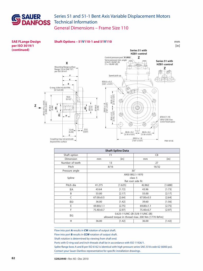
82 520L0440 • Rev AE • Dec 2010
Series 51 and 51-1 Bent Axis Variable Displacement MotorsTechnical Information
Flow into port A results in CW rotation of output shaft. Flow into port B results in CCW rotation of output shaft. Shaft rotation is determined by viewing from shaft end. Ports with O-ring seal and inch threads shall be in accordance with ISO 11926/1. Splite flange boss A and B per ISO 6162 is identical with high pressure series SAE J518 code 62 (6000 psi). Contact your Sauer-Danfoss representative for specific installation drawings.
mm[in]
Shaft Options – 51V110-1 and 51V110
80.8
± 0
.2[3
.18
± 0.
01]
Ø20.5 ± 0.2[0.81 ± 0.01]
80.8
± 0
.2[3
.18
± 0.
01]
80.8 ± 0.2[3.18 ± 0.01]
80.8 ± 0.2[3.18 ± 0.01]
Ø30.0 [1.18]other side max.screw head space
200.0 ± 1.8[7.87 ± 0.07]
200.
0 ±
1.8
[7.8
7 ±
0.07
]
P001 815E
Ø15
2.37
5 ±
0.02
5[5
.999
± 0
.001
]
Ø10
0.0
[3.9
4]
Ø55
.0[2
.17]
ØG
ØA
ØD
Ø12
8.1
[5.0
4]
H
F
E
B
C
Coupling may not protrudebeyond this surface
12.45[0.49]
22.0[0.87]
R3.0[0.12]
Mounting ange surfaceange 152-4 (SAE "D")per ISO 3019/1
O-ring 3.00x142.00 FPM [0.12x5.59]
Speed pick-up
Control pressure port “X1(M3)”Servo pressure min. angle0.5625-18UNF-2B[9/16 -18UNF-2B]X
Z
Series 51 with HZB1-control
ZSeries 51 with HZB1-control
Z
General Dimensions – Frame Size 110
SAE FLange Design per ISO 3019/1(continued)
noitpotfahS 1F 8C
noisnemiD mm ]ni[ mm ]ni[
hteetforebmuN 31 72
hctiP 61/8 23/61
elgnaerusserP ˚03
enilpS0791-1.29BISNA
5ssalctifedistoortalf
aidhctiP 572.14 ]526.1[ 268.24 ]886.1[
A 46.34 ]27.1[ 69.34 ]37.1[
B 00.55 ]71.2[ 00.55 ]71.2[
C 5.0±00.76 ]46.2[ 5.0±00.76 ]46.2[
D 00.63 ]24.1[ 06.93 ]65.1[
E 1.1±08.96 ]57.2[ 1.1±08.96 ]57.2[
F 7.0±04.57 ]79.2[ 7.0±04.57 ]79.2[
G]B2-CNU11-8/5[B2-CNU11-526.0
]ni•fbl0771[mN002.xamdaerhtnieuqrotdewolla
H 00.63 ]24.1[ 00.63 ]24.1[
Shaft Spline Data

83520L0440 • Rev AE • Dec 2010
Series 51 and 51-1 Bent Axis Variable Displacement MotorsTechnical Information
mm[in]
Side Port
Axial Port
51D110-1 Two Position Control, N1NN
P001 801E
57.12
[2.25]
50.0
[1.97]
80.0
[3.15]
80.0
[3.15]
50.0
[1.97]
A B
M4
27.76
[1.09]
58.0
[2.2
7]
127.
0[4
.99]
249.0[9.81]
115.0[4.52]
77.0
[3.03]77.0
[3.03]
A B
M4
107.05[4.21]
69.05[2.72]
49.0
[1.9
2]
19°
223.0[8.77]
268.2 max.[10.56 max.]
93.5
[3.6
8]88
.5[3
.48]
232.
8[9
.16]
115.
0[4
.53]
27.76
[1.09]
57.12
[2.25]
W
Gage port “M4”System pressure max. angle0.5625-18UNF-2B[9/16 -18UNF-2B]
W
W
Gage port “M4”System pressure max. angle0.5625-18UNF-2B[9/16 -18UNF-2B]
W
Y
XY
Y
XY
Loop ushingshuttle valve
Charge pressurerelief valve
min. angle stopadjustment
Split ange boss “A”+”B”DN 25 typ II 40 MPa seriesper ISO 6162 [SAE 1.00]4 thread: 0.4375-14UNC-2B [7/16 -14UNC-2B] 27 [1.06] min. full thread depth
Case drain “L1”1.0625-12UN-2B[1 1/16 -12UN-2B]
Alternate positionCase drain “L2”1.0625-12UN-2B[1 1/16 -12UN-2B]
Gage port “M1”System pressure “A” 1.0625-12UNF-2B[1 1/16 -12UNF-2B]
Gage port “M2”System pressure “B” 1.0625-12UNF-2B[1 1/16 -12UNF-2B]
Gage ports “M1”+”M2”System pressure “A”+”B” 0.5625-18UNF-2B[9/16 -18UNF-2B]
Split ange boss “A”DN 25 typ II 40 MPa seriesper ISO 6162 [SAE 1.00]4 thread: 0.4375-14UNC-2B [7/16 -14UNC-2B] 27 [1.06] min. full thread depth
Split ange boss “B”DN 25 typ II 40 MPa seriesper ISO 6162 [SAE 1.00]4 thread: 0.4375-14UNC-2B [7/16 -14UNC-2B] 27 [1.06] min. full thread depth
General Dimensions – Frame Size 110
DIN Flange Designper ISO 3019/2
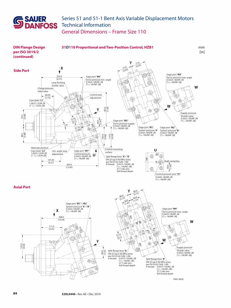
84 520L0440 • Rev AE • Dec 2010
Series 51 and 51-1 Bent Axis Variable Displacement MotorsTechnical Information
Side Port
mm[in]
Axial Port
P001 802E
50.0
[1.97]
57.15
[2.25]
80.0
[3.15]
80.0
[3.15]
50.0
[1.97]
M3
M5
M4
A B
27.76
[1.09]
Split ange boss “A”DN 25 typ II 40 MPa seriesper ISO 6162 [SAE 1.00]4 thread: 0.4375-14UNC-2B [7/16 -14UNC-2B] 27 [1.06] min. full thread depth
Split ange boss “B”DN 25 typ II 40 MPa seriesper ISO 6162 [SAE 1.00]4 thread: 0.4375-14UNC-2B [7/16 -14UNC-2B] 27 [1.06] min. full thread depth
Gage port “M1”+”M2”System pressure “A”+”B”0.5625-18UNF-2B[9/16 -18UNF-2B]
268.0[10.54]
64.0
[2.5
3]
125.
0[4
.94]
111.0[4.35]
Charge pressurerelief valve
107.05[4.21]
69.05[2.72]
Control startadjustment
Gage port “M3”Servo pressure min. angle0.5625-18UNF-2B[9/16 -18UNF-2B]
Gage port “M5”Servo pressure supply0.5625-18UNF-2B[9/16 -18UNF-2B]
Control mountingsurface
Loop ushingshuttle valve
305.0[12.00]
88.5
[3.4
8]93
.5[3
.68]
185.
0 [7
.30]
103.
0[4
.06]
49.0
[1.9
1]
222.0[8.75]
19°
Case drain “L1”1.0625-12UN-2B[1 1/16 -12UN-2B]
min. angle stopadjustment
Gage port “M7”Control pressure0.5625-18UNF-2B[9/16 -18UNF-2B]
114.
0[4
.50]
A
M1
M5
M3
57.15
[2.25]
27.76
[1.09]
Split ange boss “A”+”B”DN 25 typ II 40 MPa seriesper ISO 6162 [SAE 1.00]4 thread: 0.4375-14UNC-2B [7/16 -14UNC-2B] 27 [1.06] min. full thread depth
Alternate positionCase drain “L2”1.0625-12UN-2B[1 1/16 -12UN-2B]
Gage port “M1”System pressure “A” 0.5625-18UNF-2B[9/16 -18UNF-2B]
Gage port “M2”System pressure “B” 0.5625-18UNF-2B[9/16 -18UNF-2B]
77.0
[3.03]
77.0
[3.03]
Y
X
U
Y
Y
Y
X
Shaft centerline
Control pressure port “X1”0.5625-18UNF-2B[9/16 -18UNF-2B]
U
X1
M7
49.0
[1.9
3]
Supply pressureShuttle valve0.5625-18UNF-2B[9/16 -18UNF-2B]
Gage port “M4”Servo pressure max. angle0.5625-18UNF-2B[9/16 -18UNF-2B]
W
W
M4
Supply pressureShuttle valve0.5625-18UNF-2B[9/16 -18UNF-2B]
Gage port “M4”Servo pressure max. angle0.5625-18UNF-2B[9/16 -18UNF-2B]
W
W
M4
51D110 Proportional and Two-Position Control, HZB1
General Dimensions – Frame Size 110
DIN Flange Designper ISO 3019/2(continued)
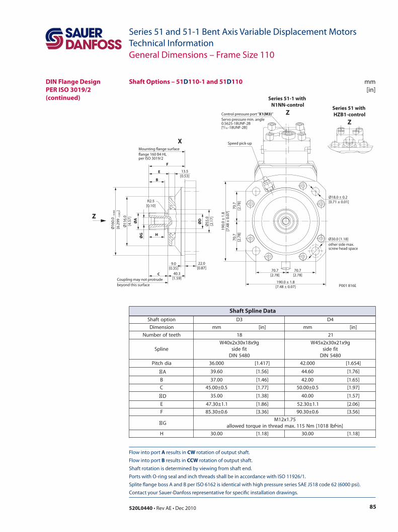
85520L0440 • Rev AE • Dec 2010
Series 51 and 51-1 Bent Axis Variable Displacement MotorsTechnical Information
Flow into port A results in CW rotation of output shaft. Flow into port B results in CCW rotation of output shaft. Shaft rotation is determined by viewing from shaft end. Ports with O-ring seal and inch threads shall be in accordance with ISO 11926/1. Splite flange boss A and B per ISO 6162 is identical with high pressure series SAE J518 code 62 (6000 psi). Contact your Sauer-Danfoss representative for specific installation drawings.
mm[in]
Shaft Options – 51D110-1 and 51D110
General Dimensions – Frame Size 110
noitpotfahS 3D 4D
noisnemiD mm ]ni[ mm ]ni[
hteetforebmuN 81 12
enilpSg9x81x03x2x04W
tifedis0845NID
g9x12x03x2x54Wtifedis0845NID
aidhctiP 000.63 ]714.1[ 000.24 ]456.1[
A 06.93 ]65.1[ 06.44 ]67.1[
B 00.73 ]64.1[ 00.24 ]56.1[
C 5.0±00.54 ]77.1[ 5.0±00.05 ]79.1[
D 00.53 ]83.1[ 00.04 ]75.1[
E 1.1±03.74 ]68.1[ 1.1±03.25 ]60.2[
F 6.0±03.58 ]63.3[ 6.0±03.09 ]65.3[
G57.1x21M
]ni•fbl8101[mN511.xamdaerhtnieuqrotdewolla
H 00.03 ]81.1[ 00.03 ]81.1[
Shaft Spline Data
DIN Flange DesignPER ISO 3019/2(continued)
P001 816E
ØG
ØA
ØD
Ø55
.0[2
.17]
Ø11
6.0
[4.5
7]
H
F
E
B
C
Coupling may not protrudebeyond this surface
Ø16
0.0
- 0.0
63
[6.2
99 - 0
.002
]
22.0[0.87]
40.3[1.59]
9.0[0.35]
R2.5[0.10]
Ø18.0 ± 0.2[0.71 ± 0.01]
Ø30.0 [1.18]other side max.screw head space
70.7[2.78]
70.7[2.78]
190.0 ± 1.8[7.48 ± 0.07]
70.7
[2.7
8]70
.7[2
.78]
190.
0 ±
1.8
[7.4
8 ±
0.0
7]
Mounting flange surfaceflange 160 B4 HLper ISO 3019/2
13.5[0.53]
Speed pick-up
Control pressure port “X1(M3)”Servo pressure min. angle0.5625-18UNF-2B[9/16 -18UNF-2B]
X
Z
Series 51 with HZB1-control
Z
Series 51-1 with N1NN-control
Z
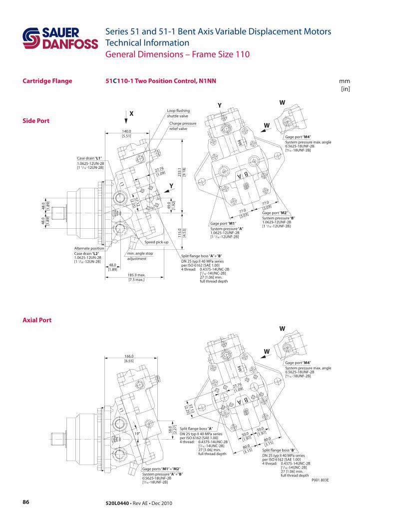
86 520L0440 • Rev AE • Dec 2010
Series 51 and 51-1 Bent Axis Variable Displacement MotorsTechnical Information
mm[in]
Side Port
Axial Port
51C110-1 Two Position Control, N1NN
P001 803E
58.0
[2.2
7]
166.0[6.55]
L1
19°
57.12
[2.25]
50.0
[1.97]
80.0
[3.15]
80.0
[3.15]
50.0
[1.97]
A B
M4
27.76
[1.09]
77.0
[3.03]77.0
[3.03]
A B
M4
48.0[1.89]
49.0
[1.9
2]
140.0[5.51]
185.3 max.[7.3 max.]
48.0
[1.8
9]48
.0[1
.89]
233.
1[9
.18]
115.
0[4
.53]
27.76
[1.09]
L1
57.12
[2.25]
Loop ushingshuttle valve
Charge pressurerelief valve
min. angle stopadjustment
Split ange boss “A”+”B”DN 25 typ II 40 MPa seriesper ISO 6162 [SAE 1.00]4 thread: 0.4375-14UNC-2B [7/16 -14UNC-2B] 27 [1.06] min. full thread depth
Case drain “L1”1.0625-12UN-2B[1 1/16 -12UN-2B]
Alternate positionCase drain “L2”1.0625-12UN-2B[1 1/16 -12UN-2B]
Gage port “M1”System pressure “A” 1.0625-12UNF-2B[1 1/16 -12UNF-2B]
Gage port “M2”System pressure “B” 1.0625-12UNF-2B[1 1/16 -12UNF-2B]
W
Gage port “M4”System pressure max. angle0.5625-18UNF-2B[9/16 -18UNF-2B]
W
W
Gage port “M4”System pressure max. angle0.5625-18UNF-2B[9/16 -18UNF-2B]
W
Y
XY
Gage ports “M1”+”M2”System pressure “A”+”B” 0.5625-18UNF-2B[9/16 -18UNF-2B]
Split ange boss “A”DN 25 typ II 40 MPa seriesper ISO 6162 [SAE 1.00]4 thread: 0.4375-14UNC-2B [7/16 -14UNC-2B] 27 [1.06] min. full thread depth
Split ange boss “B”DN 25 typ II 40 MPa seriesper ISO 6162 [SAE 1.00]4 thread: 0.4375-14UNC-2B [7/16 -14UNC-2B] 27 [1.06] min. full thread depth
Speed pick-up
General Dimensions – Frame Size 110
Cartridge Flange
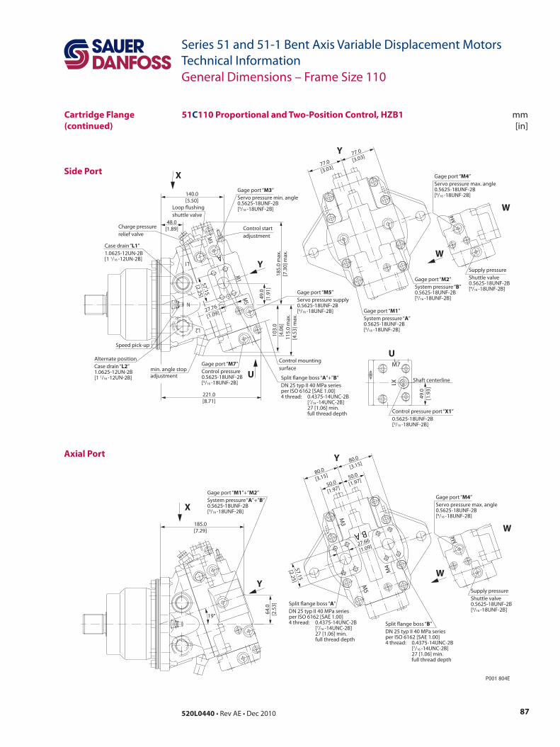
87520L0440 • Rev AE • Dec 2010
Series 51 and 51-1 Bent Axis Variable Displacement MotorsTechnical Information
mm[in]
Side Port
Axial Port
L2
A
M3
M1
M5N
L1
P001 804E
Gage port “M2”System pressure “B” 0.5625-18UNF-2B[9/16 -18UNF-2B]
Gage port “M1”System pressure “A” 0.5625-18UNF-2B[9/16 -18UNF-2B]
77.0
[3.03]
77.0
[3.03]
48.0[1.89] Control start
adjustment
Gage port “M3”Servo pressure min. angle0.5625-18UNF-2B[9/16 -18UNF-2B]
Gage port “M5”Servo pressure supply0.5625-18UNF-2B[9/16 -18UNF-2B]
Control mountingsurface
221.0[8.71]
185.
0 m
ax.
[7.3
0] m
ax.
103.
0[4
.06]
49.0
[1.9
1]
140.0[5.50]
Alternate positionCase drain “L2”1.0625-12UN-2B[1 1/16 -12UN-2B]
Case drain “L1”1.0625-12UN-2B[1 1/16 -12UN-2B]
Gage port “M7”Control pressure0.5625-18UNF-2B[9/16 -18UNF-2B]
115.
0 m
ax.
[4.5
3] m
ax.
57.15
[2.25]
27.76
[1.09]
Charge pressurerelief valve
Loop ushingshuttle valve
Split ange boss “A”+”B”DN 25 typ II 40 MPa seriesper ISO 6162 [SAE 1.00]4 thread: 0.4375-14UNC-2B [7/16 -14UNC-2B] 27 [1.06] min. full thread depth
min. angle stopadjustment
Speed pick-up
M3
M4
M5
A B
27.66
[1.09]
50.0
[1.97]
50.0
[1.97]80.0
[3.15]
80.0
[3.15]
57.15
[2.25]
Split ange boss “A”DN 25 typ II 40 MPa seriesper ISO 6162 [SAE 1.00]4 thread: 0.4375-14UNC-2B [7/16 -14UNC-2B] 27 [1.06] min. full thread depth
Split ange boss “B”DN 25 typ II 40 MPa seriesper ISO 6162 [SAE 1.00]4 thread: 0.4375-14UNC-2B [7/16 -14UNC-2B] 27 [1.06] min. full thread depth
Gage port “M1”+”M2”System pressure “A”+”B”0.5625-18UNF-2B[9/16 -18UNF-2B]
185.0[7.29]
64.0
[2.5
3]
19°
Shaft centerline
Control pressure port “X1”0.5625-18UNF-2B[9/16 -18UNF-2B]
U
X1
M7
49.0
[1.9
3]
Supply pressureShuttle valve0.5625-18UNF-2B[9/16 -18UNF-2B]
Gage port “M4”Servo pressure max. angle0.5625-18UNF-2B[9/16 -18UNF-2B]
W
W
M4
Supply pressureShuttle valve0.5625-18UNF-2B[9/16 -18UNF-2B]
Gage port “M4”Servo pressure max. angle0.5625-18UNF-2B[9/16 -18UNF-2B]
W
W
M4
Y
X
U
Y
Y
Y
X
51C110 Proportional and Two-Position Control, HZB1
General Dimensions – Frame Size 110
Cartridge Flange(continued)
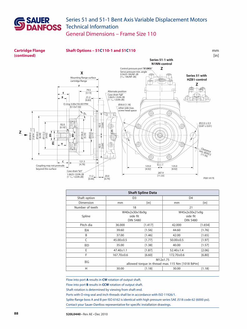
88 520L0440 • Rev AE • Dec 2010
Series 51 and 51-1 Bent Axis Variable Displacement MotorsTechnical Information
Flow into port A results in CW rotation of output shaft. Flow into port B results in CCW rotation of output shaft. Shaft rotation is determined by viewing from shaft end. Ports with O-ring seal and inch threads shall be in accordance with ISO 11926/1. Splite flange boss A and B per ISO 6162 is identical with high pressure series SAE J518 code 62 (6000 psi). Contact your Sauer-Danfoss representative for specific installation drawings.
mm[in]
P001 817E
125.0[4.92]
125.0[4.92]
Ø22.0 ± 0.3[0.87 ± 0.01]
287.9[11.33]
Ø30.0 [1.18]other side max. screw head space
ØG
ØA
Ø11
2.2
[4.4
2]
Ø16
0.0
[6.3
0]
H
B
45°
E79.5
[3.13]
121.3[4.78]
F
C
Coupling may not protrudebeyond this surface
11.2[0.44]
20.0[0.79]
Ø20
0.0
- 0.0
29
[7.8
74 - 0
.001
]
R2.0[0.10] M
3
ØD
Ø55
.0[2
.17]
92.5
[3.6
4]
Ø13
6.0
[5.3
5]
21.2[0.83]
Clearancemin. Ø293.5[11.56]
92.5
[3.6
4]O-ring 3.00x192.00 FPM [0.12x7.56]
Mounting ange surfacecartridge ange
Alternate positionCase drain “L2”1.0625-12UN-2B[1 1/16 -12UN-2B]
Case drain “L1”1.0625-12UN-2B[1 1/16 -12UN-2B]
Control pressure port “X1(M3)”Servo pressure min. angle0.5625-18UNF-2B[9/16 -18UNF-2B]
X
Z
Series 51 with HZB1-control
Z
Series 51-1 with N1NN-control
Z
Shaft Options – 51C110-1 and 51C110
General Dimensions – Frame Size 110
Cartridge Flange(continued)
noitpotfahS 3D 4D
noisnemiD mm ]ni[ mm ]ni[
hteetforebmuN 81 12
enilpSg9x81x03x2x04W
tifedis0845NID
g9x12x03x2x54Wtifedis0845NID
aidhctiP 000.63 ]714.1[ 000.24 ]456.1[
A 06.93 ]65.1[ 06.44 ]67.1[
B 00.73 ]64.1[ 00.24 ]56.1[
C 5.0±00.54 ]77.1[ 5.0±00.05 ]79.1[
D 00.53 ]83.1[ 00.04 ]75.1[
E 1.1±04.74 ]78.1[ 4.1±04.25 ]60.2[
F 6.0±07.761 ]06.6[ 6.0±07.271 ]08.6[
G57.1x21M
]ni•fbl8101[mN511.xamdaerhtnieuqrotdewolla
H 00.03 ]81.1[ 00.03 ]81.1[
Shaft Spline Data

89520L0440 • Rev AE • Dec 2010
Series 51 and 51-1 Bent Axis Variable Displacement MotorsTechnical InformationNotes
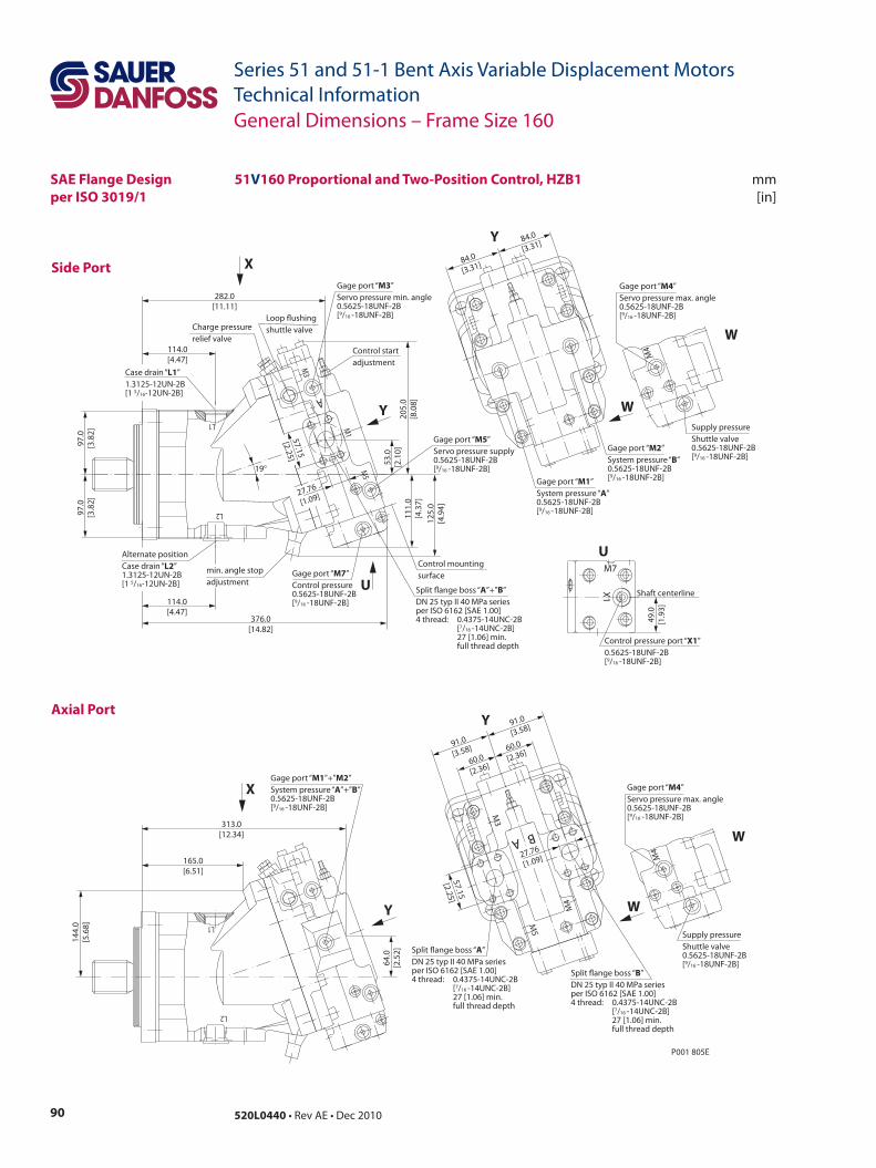
90 520L0440 • Rev AE • Dec 2010
Series 51 and 51-1 Bent Axis Variable Displacement MotorsTechnical Information
Side Port
mm[in]
Axial Port
M3
M5
M1
A
L1
L2
P001 805E
60.0
[2.36]
57.15
[2.25]
60.0
[2.36]91.0
[3.58]
91.0
[3.58]
A BM
5
M4
M3
27.76
[1.09]
Split ange boss “A”DN 25 typ II 40 MPa seriesper ISO 6162 [SAE 1.00]4 thread: 0.4375-14UNC-2B [7/16 -14UNC-2B] 27 [1.06] min. full thread depth
Split ange boss “B”DN 25 typ II 40 MPa seriesper ISO 6162 [SAE 1.00]4 thread: 0.4375-14UNC-2B [7/16 -14UNC-2B] 27 [1.06] min. full thread depth
Gage port “M1”+”M2”System pressure “A”+”B”0.5625-18UNF-2B[9/16 -18UNF-2B]
313.0[12.34]
64.0
[2.5
2]
144.
0[5
.68]
165.0[6.51]
Gage port “M2”System pressure “B” 0.5625-18UNF-2B[9/16 -18UNF-2B]Gage port “M1”
System pressure “A” 0.5625-18UNF-2B[9/16 -18UNF-2B]
84.0
[3.31]
84.0
[3.31]
114.0[4.47]
114.0[4.47]
Control startadjustment
Gage port “M3”Servo pressure min. angle0.5625-18UNF-2B[9/16 -18UNF-2B]
Gage port “M5”Servo pressure supply0.5625-18UNF-2B[9/16 -18UNF-2B]
Control mountingsurface
Loop ushingshuttle valve
376.0[14.82]
97.0
[3.8
2]97
.0[3
.82]
205.
0[8
.08]
111.
0[4
.37]
53.0
[2.1
0]
282.0[11.11]
Alternate positionCase drain “L2”1.3125-12UN-2B[1 5/16-12UN-2B]
19°
Gage port “M7”Control pressure0.5625-18UNF-2B[9/16 -18UNF-2B]
125.
0[4
.94]
27.76
[1.09]
57.15
[2.25]Split ange boss “A”+”B”DN 25 typ II 40 MPa seriesper ISO 6162 [SAE 1.00]4 thread: 0.4375-14UNC-2B [7/16 -14UNC-2B] 27 [1.06] min. full thread depth
min. angle stopadjustment
L1
L2
Y
X
U
Y
Y
Y
X
Charge pressurerelief valve
Case drain “L1”1.3125-12UN-2B[1 5/16-12UN-2B]
Shaft centerline
Control pressure port “X1”0.5625-18UNF-2B[9/16 -18UNF-2B]
U
X1
M7
49.0
[1.9
3]
Supply pressureShuttle valve0.5625-18UNF-2B[9/16 -18UNF-2B]
Gage port “M4”Servo pressure max. angle0.5625-18UNF-2B[9/16 -18UNF-2B]
W
W
M4
Supply pressureShuttle valve0.5625-18UNF-2B[9/16 -18UNF-2B]
Gage port “M4”Servo pressure max. angle0.5625-18UNF-2B[9/16 -18UNF-2B]
W
W
M4
51V160 Proportional and Two-Position Control, HZB1
General Dimensions – Frame Size 160
SAE Flange Designper ISO 3019/1
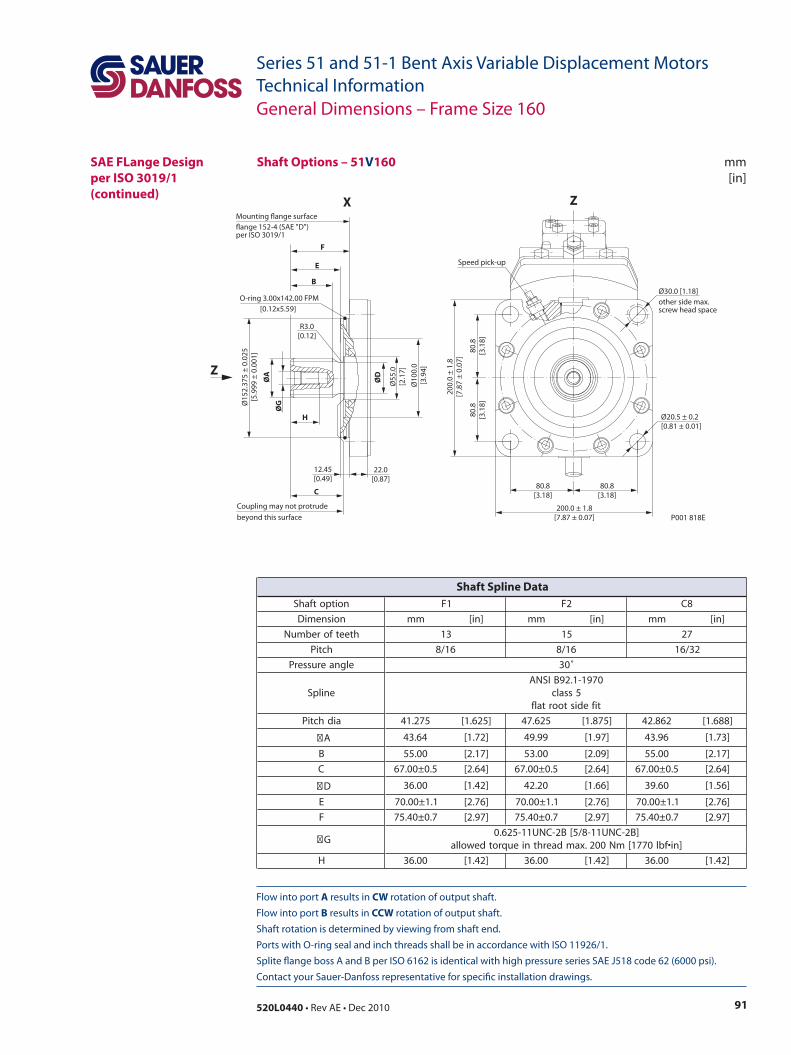
91520L0440 • Rev AE • Dec 2010
Series 51 and 51-1 Bent Axis Variable Displacement MotorsTechnical Information
Flow into port A results in CW rotation of output shaft. Flow into port B results in CCW rotation of output shaft. Shaft rotation is determined by viewing from shaft end. Ports with O-ring seal and inch threads shall be in accordance with ISO 11926/1. Splite flange boss A and B per ISO 6162 is identical with high pressure series SAE J518 code 62 (6000 psi). Contact your Sauer-Danfoss representative for specific installation drawings.
mm[in]
Shaft Options – 51V160
Ø15
2.37
5 ±
0.02
5[5
.999
± 0
.001
]
Ø10
0.0
[3.9
4]
Ø55
.0[2
.17]
ØG
ØA
ØD
H
F
E
B
C
Coupling may not protrudebeyond this surface
12.45[0.49]
22.0[0.87]
R3.0[0.12]
P001 818E
80.8[3.18]
80.8[3.18]
Ø20.5 ± 0.2[0.81 ± 0.01]
80.8
[3.1
8]80
.8[3
.18]
200.
0 ±
1.8
[7.8
7 ±
0.07
]
200.0 ± 1.8[7.87 ± 0.07]
Speed pick-up
Mounting ange surfaceange 152-4 (SAE "D")per ISO 3019/1
O-ring 3.00x142.00 FPM [0.12x5.59]
Ø30.0 [1.18]other side max.screw head space
Z
X Z
SAE FLange Design per ISO 3019/1(continued)
General Dimensions – Frame Size 160
noitpotfahS 1F 2F 8C
noisnemiD mm ]ni[ mm ]ni[ mm ]ni[
hteetforebmuN 31 51 72
hctiP 61/8 61/8 23/61
elgnaerusserP ˚03
enilpS0791-1.29BISNA
5ssalctifedistoortalf
aidhctiP 572.14 ]526.1[ 526.74 ]578.1[ 268.24 ]886.1[
A 46.34 ]27.1[ 99.94 ]79.1[ 69.34 ]37.1[
B 00.55 ]71.2[ 00.35 ]90.2[ 00.55 ]71.2[
C 5.0±00.76 ]46.2[ 5.0±00.76 ]46.2[ 5.0±00.76 ]46.2[
D 00.63 ]24.1[ 02.24 ]66.1[ 06.93 ]65.1[
E 1.1±00.07 ]67.2[ 1.1±00.07 ]67.2[ 1.1±00.07 ]67.2[
F 7.0±04.57 ]79.2[ 7.0±04.57 ]79.2[ 7.0±04.57 ]79.2[
G]B2-CNU11-8/5[B2-CNU11-526.0
]ni•fbl0771[mN002.xamdaerhtnieuqrotdewolla
H 00.63 ]24.1[ 00.63 ]24.1[ 00.63 ]24.1[
Shaft Spline Data
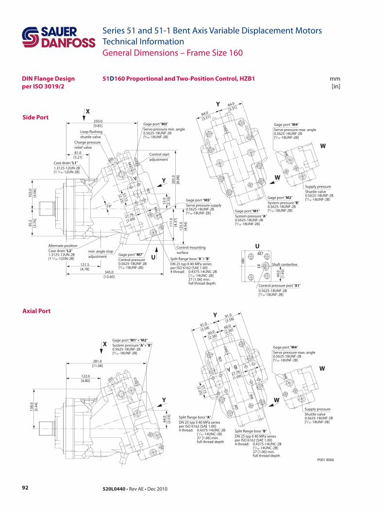
92 520L0440 • Rev AE • Dec 2010
Series 51 and 51-1 Bent Axis Variable Displacement MotorsTechnical Information
Side Port
mm[in]
Axial Port
P001 806E
281.0[11.08]
64.0
[2.5
3]
138.
0[5
.44]
122.0[4.80]
60.0
[2.36]
57.15
[2.25]
91.0
[3.58]
91.0
[3.58]
60.0
[2.36]
M4
M5
M3
BA
27.76
[1.09]
84.0
[3.31]
84.0
[3.31]
121.5[4.78]
81.0[3.21]
345.0[13.60]
95.5
[3.7
6]10
3.0
[4.0
6]
205.
0[8
.08]
111.
0[4
.37]
53.0
[2.1
0]
250.0[9.85]
19°
125.
0[4
.94]
A
M1
M5
M3
27.76
[1.09]
57.15
[2.25]
Split ange boss “A”DN 25 typ II 40 MPa seriesper ISO 6162 [SAE 1.00]4 thread: 0.4375-14UNC-2B [7/16 -14UNC-2B] 27 [1.06] min. full thread depth
Split ange boss “B”DN 25 typ II 40 MPa seriesper ISO 6162 [SAE 1.00]4 thread: 0.4375-14UNC-2B [7/16 -14UNC-2B] 27 [1.06] min. full thread depth
Gage port “M1”+”M2”System pressure “A”+”B”0.5625-18UNF-2B[9/16 -18UNF-2B]
Y
Y
X
Control startadjustment
Gage port “M3”Servo pressure min. angle0.5625-18UNF-2B[9/16 -18UNF-2B]
Gage port “M5”Servo pressure supply0.5625-18UNF-2B[9/16 -18UNF-2B]
Control mountingsurface
Loop ushingshuttle valve
Alternate positionCase drain “L2”1.3125-12UN-2B[1 5/16 -12UN-2B]
Gage port “M7”Control pressure0.5625-18UNF-2B[9/16 -18UNF-2B]
Split ange boss “A”+”B”DN 25 typ II 40 MPa seriesper ISO 6162 [SAE 1.00]4 thread: 0.4375-14UNC-2B [7/16 -14UNC-2B] 27 [1.06] min. full thread depth
min. angle stopadjustment
Y
X
Charge pressurerelief valve
Case drain “L1”1.3125-12UN-2B[1 5/16 -12UN-2B]
Gage port “M2”System pressure “B” 0.5625-18UNF-2B[9/16 -18UNF-2B]Gage port “M1”
System pressure “A” 0.5625-18UNF-2B[9/16 -18UNF-2B]
Y
Shaft centerline
Control pressure port “X1”0.5625-18UNF-2B[9/16 -18UNF-2B]
U
X1
M7
49.0
[1.9
3]
Supply pressureShuttle valve0.5625-18UNF-2B[9/16 -18UNF-2B]
Gage port “M4”Servo pressure max. angle0.5625-18UNF-2B[9/16 -18UNF-2B]
W
W
M4
Supply pressureShuttle valve0.5625-18UNF-2B[9/16 -18UNF-2B]
Gage port “M4”Servo pressure max. angle0.5625-18UNF-2B[9/16 -18UNF-2B]
W
W
M4
U
51D160 Proportional and Two-Position Control, HZB1
General Dimensions – Frame Size 160
DIN Flange Designper ISO 3019/2
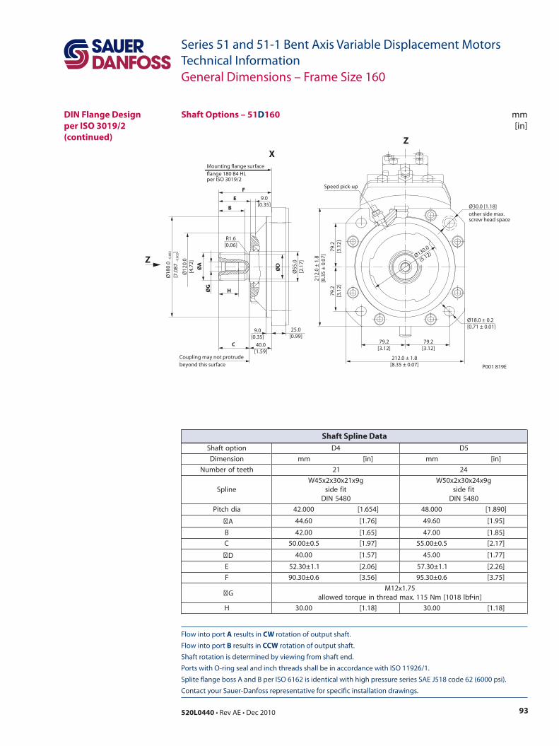
93520L0440 • Rev AE • Dec 2010
Series 51 and 51-1 Bent Axis Variable Displacement MotorsTechnical Information
Flow into port A results in CW rotation of output shaft. Flow into port B results in CCW rotation of output shaft. Shaft rotation is determined by viewing from shaft end. Ports with O-ring seal and inch threads shall be in accordance with ISO 11926/1. Splite flange boss A and B per ISO 6162 is identical with high pressure series SAE J518 code 62 (6000 psi). Contact your Sauer-Danfoss representative for specific installation drawings.
mm[in]
Shaft Options – 51D160
ØG
ØA
ØD
Ø55
.0[2
.17]
Ø12
0.0
[4.7
2]
H
FE
B
C
Coupling may not protrudebeyond this surface
Ø18
0.0
- 0.0
63
[7.0
87 - 0
.002
]
25.0[0.99]
40.0[1.59]
9.0[0.35]
9.0[0.35]
R1.6[0.06]
P001 819E
Speed pick-up
Ø18.0 ± 0.2[0.71 ± 0.01]
79.2[3.12]
79.2[3.12]
212.0 ± 1.8[8.35 ± 0.07]
79.2
[3.1
2]79
.2[3
.12]
212.
0 ±
1.8
[8.3
5 ±
0.07
] Ø130.0
(5.12)
Mounting ange surfaceange 180 B4 HLper ISO 3019/2
Ø30.0 [1.18]other side max.screw head space
Z
XZ
General Dimensions – Frame Size 160
DIN Flange Designper ISO 3019/2(continued)
noitpotfahS 4D 5D
noisnemiD mm ]ni[ mm ]ni[
hteetforebmuN 12 42
enilpSg9x12x03x2x54W
tifedis0845NID
g9x42x03x2x05Wtifedis0845NID
aidhctiP 000.24 ]456.1[ 000.84 ]098.1[
A 06.44 ]67.1[ 06.94 ]59.1[
B 00.24 ]56.1[ 00.74 ]58.1[
C 5.0±00.05 ]79.1[ 5.0±00.55 ]71.2[
D 00.04 ]75.1[ 00.54 ]77.1[
E 1.1±03.25 ]60.2[ 1.1±03.75 ]62.2[
F 6.0±03.09 ]65.3[ 6.0±03.59 ]57.3[
G57.1x21M
]ni•fbl8101[mN511.xamdaerhtnieuqrotdewolla
H 00.03 ]81.1[ 00.03 ]81.1[
Shaft Spline Data
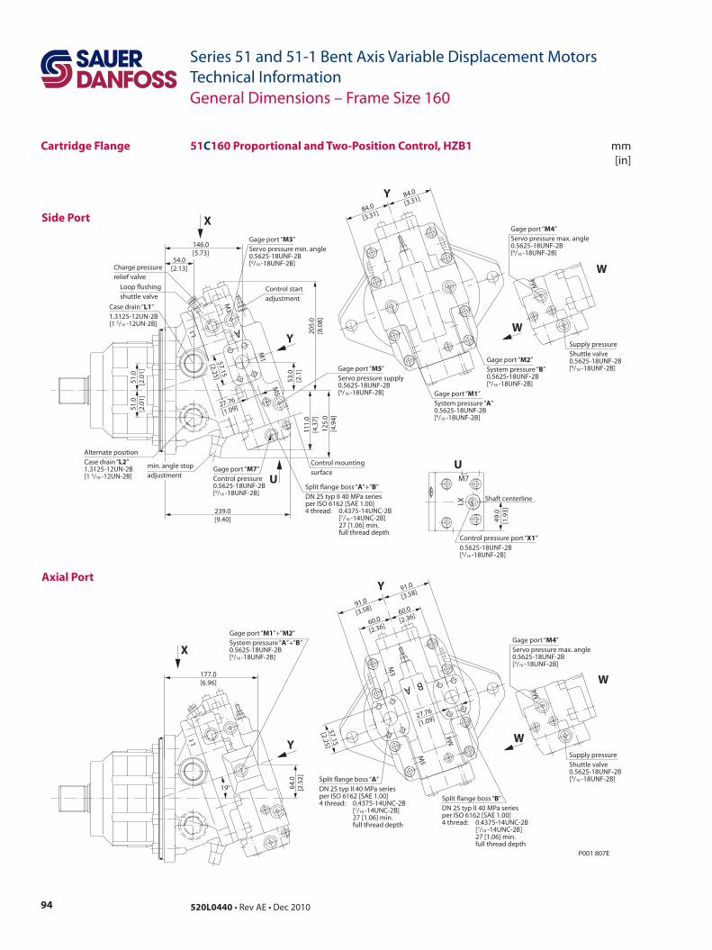
94 520L0440 • Rev AE • Dec 2010
Series 51 and 51-1 Bent Axis Variable Displacement MotorsTechnical Information
Side Port
mm[in]
Axial Port
51C160 Proportional and Two-Position Control, HZB1
P001 807E
BA
M4
M5
M3
60.0
[2.36]
91.0
[3.58]
91.0
[3.58]
60.0
[2.36]
57.15
[2.25]
27.76
[1.09]
L1
177.0[6.96]
64.0
[2.5
2]
19°
84.0
[3.31]
84.0
[3.31]L1
M5
M1
M3
A
146.0[5.73]
54.0[2.13]
239.0[9.40]
205.
0[8
.08]
125.
0[4
.94]
53.0
[2.1
]11
1.0
[4.3
7]
57.15
[2.25]
27.76
[1.09]
51.0
[2.0
1]51
.0[2
.01]
Control startadjustment
Gage port “M3”Servo pressure min. angle0.5625-18UNF-2B[9/16 -18UNF-2B]
Gage port “M5”Servo pressure supply0.5625-18UNF-2B[9/16 -18UNF-2B]
Control mountingsurface
Loop ushingshuttle valve
Alternate positionCase drain “L2”1.3125-12UN-2B[1 5/16 -12UN-2B]
Gage port “M7”Control pressure0.5625-18UNF-2B[9/16 -18UNF-2B]
Split ange boss “A”+”B”DN 25 typ II 40 MPa seriesper ISO 6162 [SAE 1.00]4 thread: 0.4375-14UNC-2B [7/16 -14UNC-2B] 27 [1.06] min. full thread depth
min. angle stopadjustment
Charge pressurerelief valve
Case drain “L1”1.3125-12UN-2B[1 5/16 -12UN-2B]
Gage port “M2”System pressure “B” 0.5625-18UNF-2B[9/16 -18UNF-2B]
Gage port “M1”System pressure “A” 0.5625-18UNF-2B[9/16 -18UNF-2B]
Y
X
Y
UShaft centerline
Control pressure port “X1”0.5625-18UNF-2B[9/16 -18UNF-2B]
U
X1
M7
49.0
[1.9
3]
Supply pressureShuttle valve0.5625-18UNF-2B[9/16 -18UNF-2B]
Gage port “M4”Servo pressure max. angle0.5625-18UNF-2B[9/16 -18UNF-2B]
W
W
M4
Supply pressureShuttle valve0.5625-18UNF-2B[9/16 -18UNF-2B]
Gage port “M4”Servo pressure max. angle0.5625-18UNF-2B[9/16 -18UNF-2B]
W
W
M4
Split ange boss “A”DN 25 typ II 40 MPa seriesper ISO 6162 [SAE 1.00]4 thread: 0.4375-14UNC-2B [7/16 -14UNC-2B] 27 [1.06] min. full thread depth
Split ange boss “B”DN 25 typ II 40 MPa seriesper ISO 6162 [SAE 1.00]4 thread: 0.4375-14UNC-2B [7/16 -14UNC-2B] 27 [1.06] min. full thread depth
Gage port “M1”+”M2”System pressure “A”+”B”0.5625-18UNF-2B[9/16 -18UNF-2B]
Y
Y
X
Cartridge Flange
General Dimensions – Frame Size 160
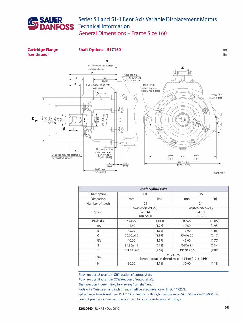
95520L0440 • Rev AE • Dec 2010
Series 51 and 51-1 Bent Axis Variable Displacement MotorsTechnical Information
Flow into port A results in CW rotation of output shaft. Flow into port B results in CCW rotation of output shaft. Shaft rotation is determined by viewing from shaft end. Ports with O-ring seal and inch threads shall be in accordance with ISO 11926/1. Splite flange boss A and B per ISO 6162 is identical with high pressure series SAE J518 code 62 (6000 psi). Contact your Sauer-Danfoss representative for specific installation drawings.
mm[in]
Shaft Options – 51C160
P001 820E
140.0[5.51]
140.0[5.51]
Ø22.0 ± 0.3[0.87 ± 0.01]
318.0 ± 2.0[12.52 ± 0.08]
11.2[0.44]
140.8 max.[5.54 max.]
20.03[0.79]
Alternate positionCase drain “L2”1.3125-12UN-2B[1 5/16 -12UN-2B]
104.
0[4
.09]
104.
0[4
.09]
Ø23
0.0
- 0.0
29
[9.0
55 - 0
.001
]
Ø18
4.0
[7.2
4]
Case drain “L1”1.3125-12UN-2B[1 5/16 -12UN-2B]
B
E 96.0[3.78]
F
H
C
Coupling may not protrudebeyond this surface
ØG
ØA
Ø12
0.0
[4.7
2]
Ø14
2.0
[5.5
9]
Ø55
.0[2
.17]
ØD
45°
Clearancemin. Ø323.6[12.74]
O-ring 3.00x220.00 FPM [0.12x8.66]
Mounting ange surfacecartridge ange
Z
XZ
Ø30.0 [1.18]other side max.screw head space
Cartridge Flange(continued)
General Dimensions – Frame Size 160
noitpotfahS 4D 5D
noisnemiD mm ]ni[ mm ]ni[
hteetforebmuN 12 42
enilpSg9x12x03x2x54W
tifedis0845NID
g9x42x03x2x05Wtifedis0845NID
aidhctiP 000.24 ]456.1[ 000.84 ]098.1[
A 06.44 ]67.1[ 06.94 ]59.1[
B 00.24 ]56.1[ 00.74 ]58.1[
C 5.0±00.05 ]79.1[ 5.0±00.55 ]71.2[
D 00.04 ]75.1[ 00.54 ]77.1[
E 4.1±05.45 ]51.2[ 4.1±05.95 ]43.2[
F 6.0±09.491 ]76.7[ 6.0±09.991 ]78.7[
G57.1x21M
]ni•fbl8101[mN511.xamdaerhtnieuqrotdewolla
H 00.03 ]81.1[ 00.03 ]81.1[
Shaft Spline Data
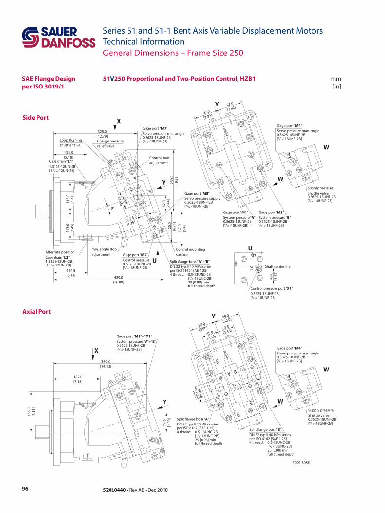
96 520L0440 • Rev AE • Dec 2010
Series 51 and 51-1 Bent Axis Variable Displacement MotorsTechnical Information
Side Port
mm[in]
Axial Port
51V250 Proportional and Two-Position Control, HZB1
A
M5
M3
M1
L2
L1
P001 808E
359.0[14.13]
74.0
[2.9
0]
155.
0[6
.11]
182.0[7.15]
97.0
[3.82]
97.0
[3.82]
131.5[5.18]
131.5[5.18]
429.0[16.89]
239.
0[9
.39]
120.
0[4
.71]
62.0
[2.4
4]
325.0[12.79]
19°
137.
0[5
.4]
31.76
[1.25]
66.68
[2.63]113.
0[4
.45]
113.
0[4
.45]
M5
M4
M3
A B
66.68
[2.63]
31.76
[1.25]
65.0
[2.56]
65.0
[2.56]99.0
[3.90]
99.0
[3.90]
L2
L1
Split ange boss “A”DN 32 typ II 40 MPa seriesper ISO 6162 [SAE 1.25]4 thread: 0.5-13UNC-2B [1/2 -13UNC-2B] 25 [0.98] min. full thread depth
Split ange boss “B”DN 32 typ II 40 MPa seriesper ISO 6162 [SAE 1.25]4 thread: 0.5-13UNC-2B [1/2 -13UNC-2B] 25 [0.98] min. full thread depth
Gage port “M1”+”M2”System pressure “A”+”B”0.5625-18UNF-2B[9/16 -18UNF-2B]
Y
Y
X
Control mountingsurface
Alternate positionCase drain “L2”1.3125-12UN-2B[1 5/16-12UN-2B]
Gage port “M7”Control pressure0.5625-18UNF-2B[9/16 -18UNF-2B]
Split ange boss “A”+”B”DN 32 typ II 40 MPa seriesper ISO 6162 [SAE 1.25]4 thread: 0.5-13UNC-2B [1/2 -13UNC-2B] 25 [0.98] min. full thread depth
min. angle stopadjustment
Loop ushingshuttle valve
Charge pressurerelief valve
Case drain “L1”1.3125-12UN-2B[1 5/16-12UN-2B]
Gage port “M3”Servo pressure min. angle0.5625-18UNF-2B[9/16 -18UNF-2B]
Gage port “M5”Servo pressure supply0.5625-18UNF-2B[9/16 -18UNF-2B]
Control startadjustment
Gage port “M1”System pressure “A” 0.5625-18UNF-2B[9/16 -18UNF-2B]
Gage port “M2”System pressure “B” 0.5625-18UNF-2B[9/16 -18UNF-2B]
Supply pressureShuttle valve0.5625-18UNF-2B[9/16 -18UNF-2B]
Gage port “M4”Servo pressure max. angle0.5625-18UNF-2B[9/16 -18UNF-2B]
W
W
M4
Supply pressureShuttle valve0.5625-18UNF-2B[9/16 -18UNF-2B]
Gage port “M4”Servo pressure max. angle0.5625-18UNF-2B[9/16 -18UNF-2B]
W
W
M4
Shaft centerline
Control pressure port “X1”0.5625-18UNF-2B[9/16 -18UNF-2B]
U
X1
M7
49.0
[1.9
3]
Y
X
Y
U
General Dimensions – Frame Size 250
SAE Flange Designper ISO 3019/1
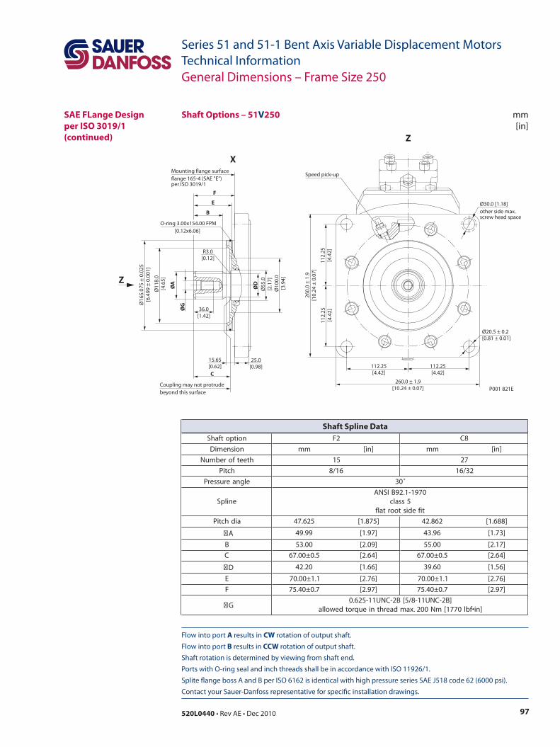
97520L0440 • Rev AE • Dec 2010
Series 51 and 51-1 Bent Axis Variable Displacement MotorsTechnical Information
Flow into port A results in CW rotation of output shaft. Flow into port B results in CCW rotation of output shaft. Shaft rotation is determined by viewing from shaft end. Ports with O-ring seal and inch threads shall be in accordance with ISO 11926/1. Splite flange boss A and B per ISO 6162 is identical with high pressure series SAE J518 code 62 (6000 psi). Contact your Sauer-Danfoss representative for specific installation drawings.
mm[in]
Shaft Options – 51V250
Ø16
5.07
5 ±
0.02
5[6
.499
± 0
.001
]
Ø10
0.0
[3.9
4]
Ø55
.0[2
.17]
ØG
ØA
ØD
Ø11
8.0
[4.6
5]
36.0[1.42]
F
E
B
C
Coupling may not protrudebeyond this surface
15.65[0.62]
25.0[0.98]
R3.0[0.12]
Speed pick-up
Ø20.5 ± 0.2[0.81 ± 0.01]
P001 821E
112.25[4.42]
112.25[4.42]
260.0 ± 1.9[10.24 ± 0.07]
112.
25[4
.42]
112.
25[4
.42]
260.
0 ±
1.9
[10.
24 ±
0.0
7]
O-ring 3.00x154.00 FPM [0.12x6.06]
Mounting ange surfaceange 165-4 (SAE "E")per ISO 3019/1
Ø30.0 [1.18]other side max.screw head space
Z
X
Z
General Dimensions – Frame Size 250
SAE FLange Design per ISO 3019/1(continued)
noitpotfahS 2F 8C
noisnemiD mm ]ni[ mm ]ni[
hteetforebmuN 51 72
hctiP 61/8 23/61
elgnaerusserP ˚03
enilpS0791-1.29BISNA
5ssalctifedistoortalf
aidhctiP 526.74 ]578.1[ 268.24 ]886.1[
A 99.94 ]79.1[ 69.34 ]37.1[
B 00.35 ]90.2[ 00.55 ]71.2[
C 5.0±00.76 ]46.2[ 5.0±00.76 ]46.2[
D 02.24 ]66.1[ 06.93 ]65.1[
E 1.1±00.07 ]67.2[ 1.1±00.07 ]67.2[
F 7.0±04.57 ]79.2[ 7.0±04.57 ]79.2[
G]B2-CNU11-8/5[B2-CNU11-526.0
]ni•fbl0771[mN002.xamdaerhtnieuqrotdewolla
Shaft Spline Data
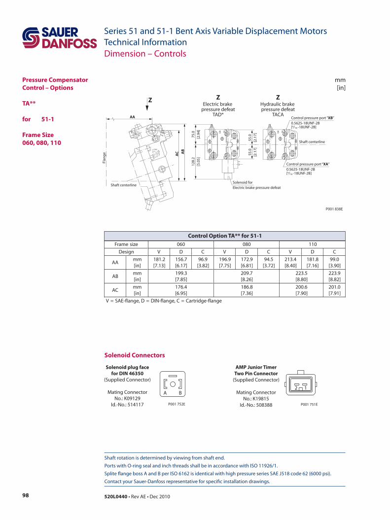
98 520L0440 • Rev AE • Dec 2010
Series 51 and 51-1 Bent Axis Variable Displacement MotorsTechnical Information
Shaft rotation is determined by viewing from shaft end. Ports with O-ring seal and inch threads shall be in accordance with ISO 11926/1. Splite flange boss A and B per ISO 6162 is identical with high pressure series SAE J518 code 62 (6000 psi). Contact your Sauer-Danfoss representative for specific installation drawings.
mm[in]
Dimension – Controls
Pressure Compensator Control – Options
TA** for 51-1
Frame Size060, 080, 110
P001 838E
AC
75.0
[2.9
4]
55.0
[2.1
7]
128.
2[5
.05]
AB
Flan
ge
AA
55.0
[2.1
7]
Solenoid forElectric brake pressure defeat
X1
M3
XAXB
X1
M3
XAXB
Shaft centerline
Shaft centerline
Control pressure port “XA” 0.5625-18UNF-2B[9/16 -18UNF-2B]
Control pressure port “XB” 0.5625-18UNF-2B[9/16 -18UNF-2B]
Z ZElectric brake
pressure defeatTAD*
ZHydraulic brake pressure defeat
TACA
Solenoid Connectors
Solenoid plug facefor DIN 46350
(Supplied Connector)
Mating ConnectorNo.: K09129
Id.-No.: 514117
A B
P001 752E
AMP Junior TimerTwo Pin Connector
(Supplied Connector)
Mating ConnectorNo.: K19815
Id.-No.: 508388
2 1
P001 751E
ezisemarF 060 080 011
ngiseD V D C V D C V D C
AAmm]ni[
2.181]31.7[
7.651]71.6[
9.69]28.3[
9.691]57.7[
9.271]18.6[
5.49]27.3[
4.312]04.8[
8.181]61.7[
0.99]09.3[
BAmm]ni[
3.991]58.7[
7.902]62.8[
5.322]08.8[
9.322]28.8[
CAmm]ni[
4.671]59.6[
8.681]63.7[
6.002]09.7[
0.102]19.7[
egnalf-egdirtraC=C,egnalf-NID=D,egnalf-EAS=V
Control Option TA** for 51-1
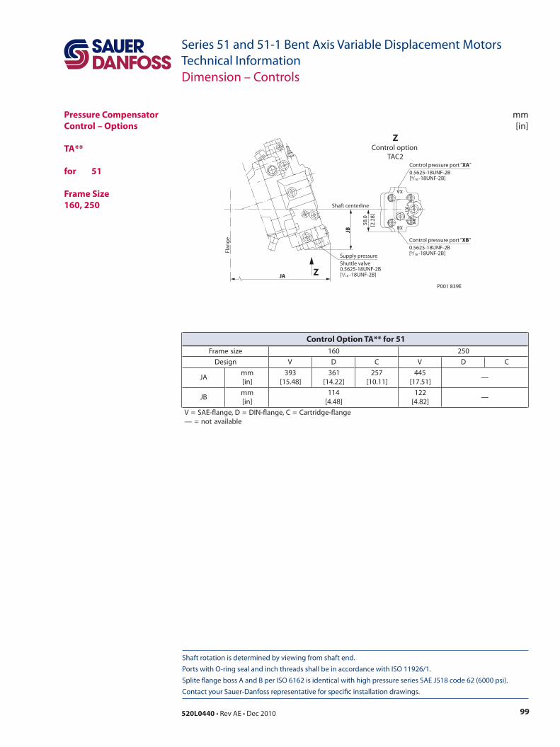
99520L0440 • Rev AE • Dec 2010
Series 51 and 51-1 Bent Axis Variable Displacement MotorsTechnical Information
mm[in]
Shaft rotation is determined by viewing from shaft end. Ports with O-ring seal and inch threads shall be in accordance with ISO 11926/1. Splite flange boss A and B per ISO 6162 is identical with high pressure series SAE J518 code 62 (6000 psi). Contact your Sauer-Danfoss representative for specific installation drawings.
Dimension – Controls
Pressure Compensator Control – Options
TA** for 51
Frame Size160, 250
Flan
ge
JA
JB
58.0
[2.2
8]
Shaft centerline
Supply pressureShuttle valve 0.5625-18UNF-2B [9/16 -18UNF-2B]
Control pressure port “XA” 0.5625-18UNF-2B[9/16 -18UNF-2B]
Control pressure port “XB” 0.5625-18UNF-2B[9/16 -18UNF-2B]
P001 839E
Z
ZControl option
TAC2X1
XB
XA
X4
ezisemarF 061 052
ngiseD V D C V D C
AJmm]ni[
393]84.51[
163]22.41[
752]11.01[
544]15.71[
—
BJmm]ni[
411]84.4[
221]28.4[
—
egnalf-egdirtraC=C,egnalf-NID=D,egnalf-EAS=Velbaliavaton=—
Control Option TA** for 51
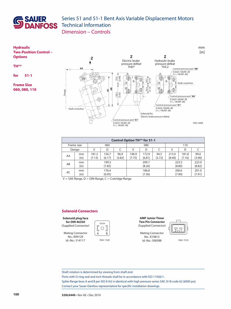
100 520L0440 • Rev AE • Dec 2010
Series 51 and 51-1 Bent Axis Variable Displacement MotorsTechnical Information
Shaft rotation is determined by viewing from shaft end. Ports with O-ring seal and inch threads shall be in accordance with ISO 11926/1. Splite flange boss A and B per ISO 6162 is identical with high pressure series SAE J518 code 62 (6000 psi). Contact your Sauer-Danfoss representative for specific installation drawings.
mm[in]
Dimension – Controls
HydraulicTwo-Position Control – Options
TH** for 51-1
Frame Size 060, 080, 110
P001 840E
X1
M3
XAXB
Shaft centerline
Control pressure port “XA” 0.5625-18UNF-2B[9/16 -18UNF-2B]
Control pressure port “X1” 0.5625-18UNF-2B[9/16 -18UNF-2B]
Control pressure port “X1” 0.5625-18UNF-2B[9/16 -18UNF-2B]
Control pressure port “XB” 0.5625-18UNF-2B[9/16 -18UNF-2B]
ZHydraulic brake pressure defeat
THC2
75.0
[2.9
4]
54.5
[2.1
5]
128.
2[5
.05]
54.5
[2.1
5]
Solenoid forElectric brake pressure defeat
X1
M3
XAXB
ZElectric brake
pressure defeatTHD*
AC A
B
Flan
ge
AA
Shaft centerline
Z
Solenoid Connectors
Solenoid plug facefor DIN 46350
(Supplied Connector)
Mating ConnectorNo.: K09129
Id.-No.: 514117
A B
P001 752E
AMP Junior TimerTwo Pin Connector
(Supplied Connector)
Mating ConnectorNo.: K19815
Id.-No.: 508388
2 1
P001 751E
ezisemarF 060 080 011
ngiseD V D C V D C V D C
AAmm]ni[
2.181]31.7[
7.651]71.6[
9.69]28.3[
9.691]57.7[
9.271]18.6[
5.49]27.3[
4.312]04.8[
8.181]61.7[
0.99]09.3[
BAmm]ni[
3.991]58.7[
7.902]62.8[
5.322]08.8[
9.322]28.8[
CAmm]ni[
4.671]59.6[
8.681]63.7[
6.002]09.7[
0.102]19.7[
egnalf-egdirtarC=C,egnalf-NID=D,egnalf-EAS=V
Control Option TH** for 51-1
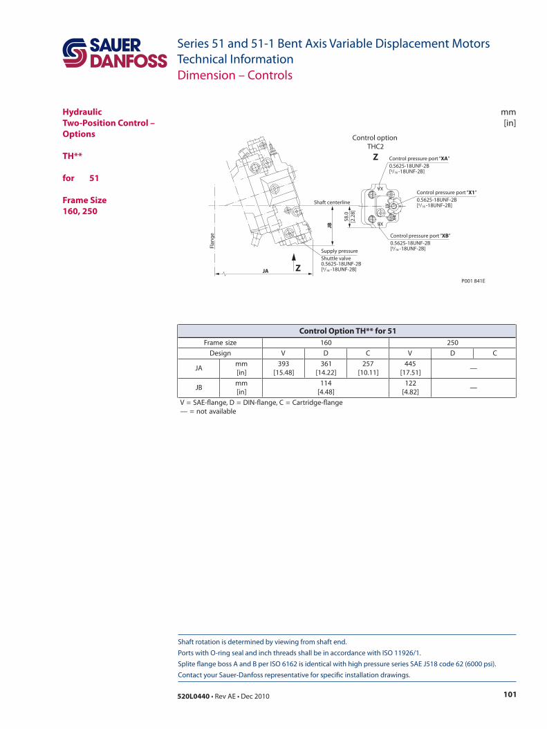
101520L0440 • Rev AE • Dec 2010
Series 51 and 51-1 Bent Axis Variable Displacement MotorsTechnical Information
mm[in]
Shaft rotation is determined by viewing from shaft end. Ports with O-ring seal and inch threads shall be in accordance with ISO 11926/1. Splite flange boss A and B per ISO 6162 is identical with high pressure series SAE J518 code 62 (6000 psi). Contact your Sauer-Danfoss representative for specific installation drawings.
Dimension – Controls
HydraulicTwo-Position Control – Options
TH**
for 51
Frame Size160, 250
Flan
ge
JA
JB
58.0
[2.2
8]
Shaft centerline
P001 841E
X1
XB
XA
X4
Supply pressureShuttle valve 0.5625-18UNF-2B [9/16 -18UNF-2B]
Control pressure port “XA” 0.5625-18UNF-2B[9/16 -18UNF-2B]
Control pressure port “X1” 0.5625-18UNF-2B[9/16 -18UNF-2B]
Control pressure port “XB” 0.5625-18UNF-2B[9/16 -18UNF-2B]
Z
Control option THC2
Z
ezisemarF 061 052
ngiseD V D C V D C
AJmm]ni[
393]84.51[
163]22.41[
752]11.01[
544]15.71[
—
BJmm]ni[
411]84.4[
221]28.4[
—
egnalf-egdirtraC=C,egnalf-NID=D,egnalf-EAS=Velbaliavaton=—
Control Option TH** for 51
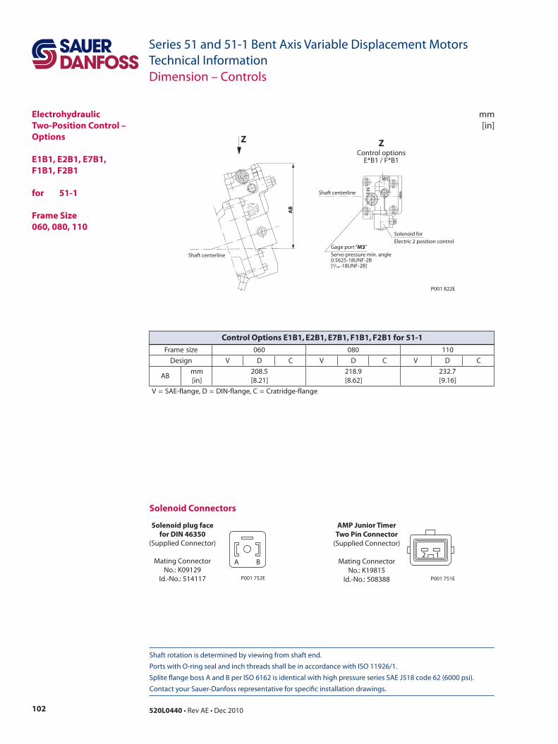
102 520L0440 • Rev AE • Dec 2010
Series 51 and 51-1 Bent Axis Variable Displacement MotorsTechnical Information
Shaft rotation is determined by viewing from shaft end. Ports with O-ring seal and inch threads shall be in accordance with ISO 11926/1. Splite flange boss A and B per ISO 6162 is identical with high pressure series SAE J518 code 62 (6000 psi). Contact your Sauer-Danfoss representative for specific installation drawings.
mm[in]
ElectrohydraulicTwo-Position Control – Options
E1B1, E2B1, E7B1,F1B1, F2B1 for 51-1
Frame Size 060, 080, 110
P001 822EA
B
M5
M3
Z ZControl options
E*B1 / F*B1
Shaft centerline
Shaft centerline
Solenoid forElectric 2 position control
Gage port “M3” Servo pressure min. angle0.5625-18UNF-2B[9/16 -18UNF-2B]
Dimension – Controls
Solenoid Connectors
Solenoid plug facefor DIN 46350
(Supplied Connector)
Mating ConnectorNo.: K09129
Id.-No.: 514117
A B
P001 752E
AMP Junior TimerTwo Pin Connector
(Supplied Connector)
Mating ConnectorNo.: K19815
Id.-No.: 508388
2 1
P001 751E
ezisemarF 060 080 011
ngiseD V D C V D C V D C
BAmm]ni[
5.802]12.8[
9.812]26.8[
7.232]61.9[
egnalf-egdirtarC=C,egnalf-NID=D,egnalf-EAS=V
Control Options E1B1, E2B1, E7B1, F1B1, F2B1 for 51-1
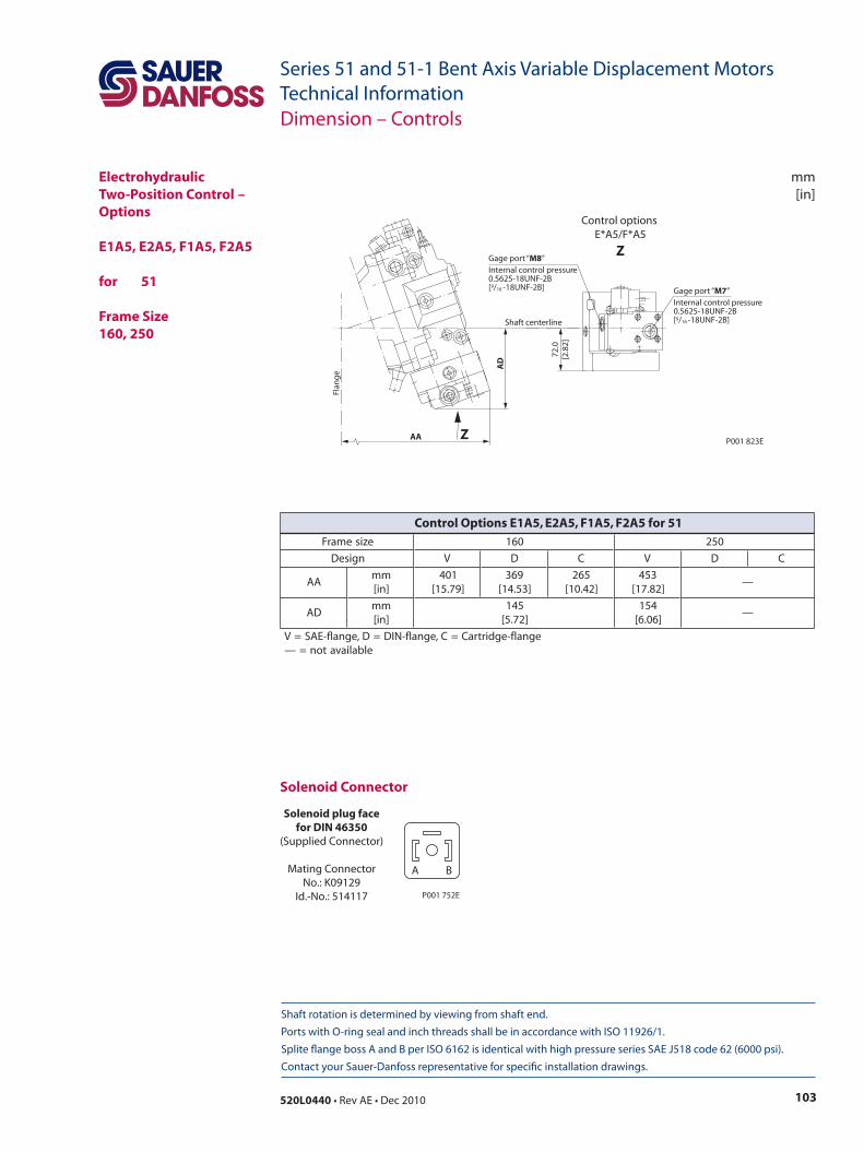
103520L0440 • Rev AE • Dec 2010
Series 51 and 51-1 Bent Axis Variable Displacement MotorsTechnical Information
mm[in]
Shaft rotation is determined by viewing from shaft end. Ports with O-ring seal and inch threads shall be in accordance with ISO 11926/1. Splite flange boss A and B per ISO 6162 is identical with high pressure series SAE J518 code 62 (6000 psi). Contact your Sauer-Danfoss representative for specific installation drawings.
ElectrohydraulicTwo-Position Control – Options
E1A5, E2A5, F1A5, F2A5
for 51
Frame Size160, 250
AD
Flan
geShaft centerline
AA
72.0
[2.8
2]
P001 823E
Gage port “M7” Internal control pressure0.5625-18UNF-2B[9/16 -18UNF-2B]
Gage port “M8” Internal control pressure0.5625-18UNF-2B[9/16 -18UNF-2B]
Z
Control options E*A5/F*A5
Z
Dimension – Controls
Solenoid Connector
Solenoid plug facefor DIN 46350
(Supplied Connector)
Mating ConnectorNo.: K09129
Id.-No.: 514117
A B
P001 752E
ezisemarF 061 052
ngiseD V D C V D C
AAmm]ni[
104]97.51[
963]35.41[
562]24.01[
354]28.71[
—
DAmm]ni[
541]27.5[
451]60.6[
—
egnalf-egdirtraC=C,egnalf-NID=D,egnalf-EAS=Velbaliavaton=—
Control Options E1A5, E2A5, F1A5, F2A5 for 51
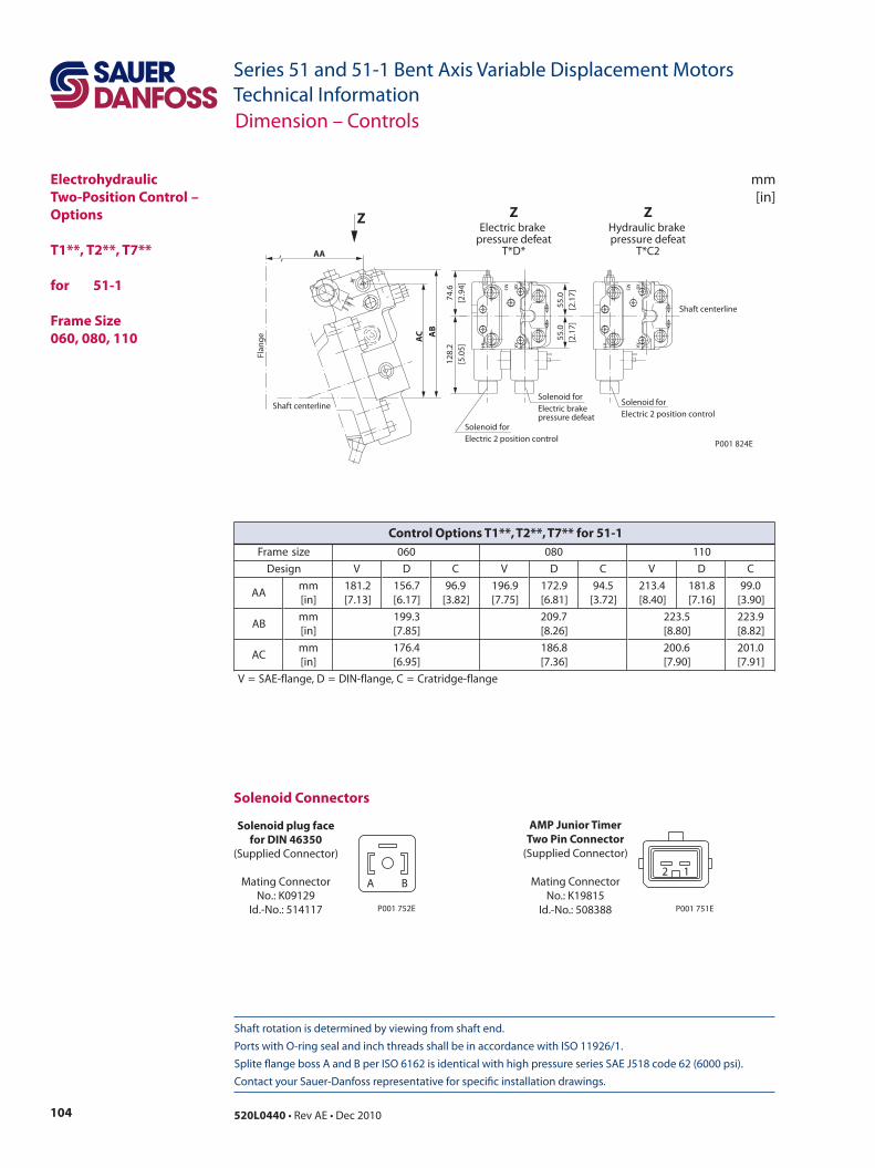
104 520L0440 • Rev AE • Dec 2010
Series 51 and 51-1 Bent Axis Variable Displacement MotorsTechnical Information
Shaft rotation is determined by viewing from shaft end. Ports with O-ring seal and inch threads shall be in accordance with ISO 11926/1. Splite flange boss A and B per ISO 6162 is identical with high pressure series SAE J518 code 62 (6000 psi). Contact your Sauer-Danfoss representative for specific installation drawings.
mm[in]
ElectrohydraulicTwo-Position Control – Options
T1**, T2**, T7**
for 51-1 Frame Size 060, 080, 110
Dimension – Controls
AC
74.6
[2.9
4]
55.0
[2.1
7]
128.
2[5
.05]
AB
Flan
ge
Shaft centerline
Shaft centerline
AA
55.0
[2.1
7]
X1
M3
XAXB
P001 824E
X1
M3
XAXB
Z ZElectric brake
pressure defeatT*D*
ZHydraulic brake pressure defeat
T*C2
Solenoid forElectric brake pressure defeat
Solenoid forElectric 2 position control
Solenoid forElectric 2 position control
Solenoid Connectors
Solenoid plug facefor DIN 46350
(Supplied Connector)
Mating ConnectorNo.: K09129
Id.-No.: 514117
A B
P001 752E
AMP Junior TimerTwo Pin Connector
(Supplied Connector)
Mating ConnectorNo.: K19815
Id.-No.: 508388
2 1
P001 751E
ezisemarF 060 080 011
ngiseD V D C V D C V D C
AAmm]ni[
2.181]31.7[
7.651]71.6[
9.69]28.3[
9.691]57.7[
9.271]18.6[
5.49]27.3[
4.312]04.8[
8.181]61.7[
0.99]09.3[
BAmm]ni[
3.991]58.7[
7.902]62.8[
5.322]08.8[
9.322]28.8[
CAmm]ni[
4.671]59.6[
8.681]63.7[
6.002]09.7[
0.102]19.7[
egnalf-egdirtarC=C,egnalf-NID=D,egnalf-EAS=V
Control Options T1**, T2**, T7** for 51-1
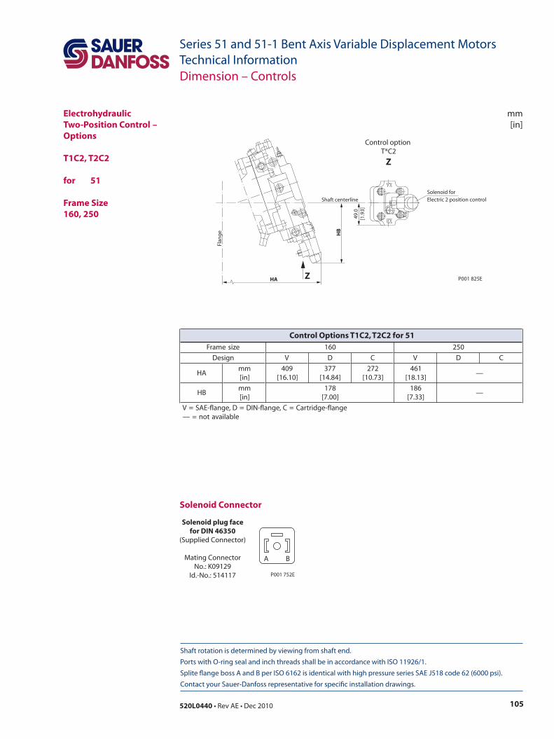
105520L0440 • Rev AE • Dec 2010
Series 51 and 51-1 Bent Axis Variable Displacement MotorsTechnical Information
mm[in]
Shaft rotation is determined by viewing from shaft end. Ports with O-ring seal and inch threads shall be in accordance with ISO 11926/1. Splite flange boss A and B per ISO 6162 is identical with high pressure series SAE J518 code 62 (6000 psi). Contact your Sauer-Danfoss representative for specific installation drawings.
Dimension – Controls
ElectrohydraulicTwo-Position Control – Options
T1C2, T2C2
for 51 Frame Size160, 250
Flan
ge
HA
HB
49.0
[1.9
3]
Shaft centerlineSolenoid forElectric 2 position control
P001 825EZ
Control option T*C2
Z
Solenoid plug facefor DIN 46350
(Supplied Connector)
Mating ConnectorNo.: K09129
Id.-No.: 514117
A B
P001 752E
Solenoid Connector
ezisemarF 061 052
ngiseD V D C V D C
AHmm]ni[
904]01.61[
773]48.41[
272]37.01[
164]31.81[
—
BHmm]ni[
871]00.7[
681]33.7[
—
egnalf-egdirtraC=C,egnalf-NID=D,egnalf-EAS=Velbaliavaton=—
Control Options T1C2, T2C2 for 51
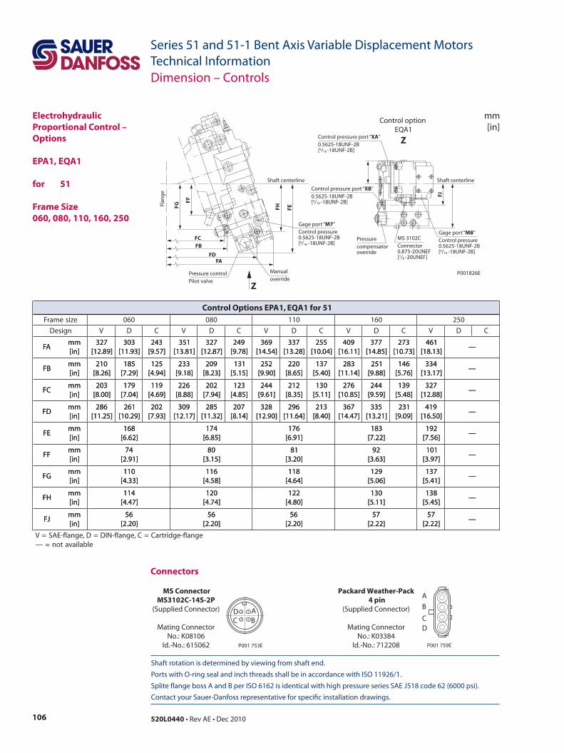
106 520L0440 • Rev AE • Dec 2010
Series 51 and 51-1 Bent Axis Variable Displacement MotorsTechnical Information
Shaft rotation is determined by viewing from shaft end. Ports with O-ring seal and inch threads shall be in accordance with ISO 11926/1. Splite flange boss A and B per ISO 6162 is identical with high pressure series SAE J518 code 62 (6000 psi). Contact your Sauer-Danfoss representative for specific installation drawings.
mm[in]
Dimension – Controls
ElectrohydraulicProportional Control – Options
EPA1, EQA1
for 51
Frame Size060, 080, 110, 160, 250
FE
FJ
FCFB
FA
FF
FG FH
FD
Control option EQA1
Z
Z
Control pressure port “XA” 0.5625-18UNF-2B[9/16 -18UNF-2B]
Control pressure port “XB” 0.5625-18UNF-2B[9/16 -18UNF-2B]
Gage port “M7” Control pressure0.5625-18UNF-2B[9/16 -18UNF-2B]
Gage port “M8” Control pressure0.5625-18UNF-2B[9/16 -18UNF-2B]
MS 3102C Connector0.875-20UNEF[7/8 -20UNEF]
Pressure compensator override
Manual override
Shaft centerline Shaft centerline
P001826E
Flan
ge
Pressure control Pilot valve
AB
DC
MS ConnectorMS3102C-14S-2P
(Supplied Connector)
Mating ConnectorNo.: K08106
Id.-No.: 615062 P001 753E
Connectors
Packard Weather-Pack 4 pin
(Supplied Connector)
Mating ConnectorNo.: K03384
Id.-No.: 712208
A
B
CD
P001 759E
ezisemarF 060 080 011 061 052
ngiseD V D C V D C V D C V D C V D C
AFmm]ni[
723]98.21[
303]39.11[
342]75.9[
153]18.31[
723]78.21[
942]87.9[
963]45.41[
733]82.31[
552]40.01[
904]11.61[
773]58.41[
372]37.01[
164]31.81[
—AFmm]ni[
723]98.21[
303]39.11[
342]75.9[
153]18.31[
723]78.21[
942]87.9[
963]45.41[
733]82.31[
552]40.01[
904]11.61[
773]58.41[
372]37.01[
164]31.81[
—
BFmm]ni[
012]62.8[
581]92.7[
521]49.4[
332]81.9[
902]32.8[
131]51.5[
252]09.9[
022]56.8[
731]04.5[
382]41.11[
152]88.9[
641]67.5[
433]71.31[
—BFmm]ni[
012]62.8[
581]92.7[
521]49.4[
332]81.9[
902]32.8[
131]51.5[
252]09.9[
022]56.8[
731]04.5[
382]41.11[
152]88.9[
641]67.5[
433]71.31[
—
CFmm]ni[
302]00.8[
971]40.7[
911]96.4[
622]88.8[
202]49.7[
321]58.4[
442]16.9[
212]53.8[
031]11.5[
672]58.01[
442]95.9[
931]84.5[
723]88.21[
—CFmm]ni[
302]00.8[
971]40.7[
911]96.4[
622]88.8[
202]49.7[
321]58.4[
442]16.9[
212]53.8[
031]11.5[
672]58.01[
442]95.9[
931]84.5[
723]88.21[
—
DFmm]ni[
682]52.11[
162]92.01[
202]39.7[
903]71.21[
582]23.11[
702]41.8[
823]09.21[
692]46.11[
312]04.8[
763]74.41[
533]12.31[
132]90.9[
914]05.61[
—DFmm]ni[
682]52.11[
162]92.01[
202]39.7[
903]71.21[
582]23.11[
702]41.8[
823]09.21[
692]46.11[
312]04.8[
763]74.41[
533]12.31[
132]90.9[
914]05.61[
—
EFmm]ni[
861]26.6[
471]58.6[
671]19.6[
381]22.7[
291]65.7[
—EFmm]ni[
861]26.6[
471]58.6[
671]19.6[
381]22.7[
291]65.7[
—
FFmm]ni[
47]19.2[
08]51.3[
18]02.3[
29]36.3[
101]79.3[
—FFmm]ni[
47]19.2[
08]51.3[
18]02.3[
29]36.3[
101]79.3[
—
GFmm]ni[
011]33.4[
611]85.4[
811]46.4[
921]60.5[
731]14.5[
—GFmm]ni[
011]33.4[
611]85.4[
811]46.4[
921]60.5[
731]14.5[
—
HFmm]ni[
411]74.4[
021]47.4[
221]08.4[
031]11.5[
831]54.5[
—HFmm]ni[
411]74.4[
021]47.4[
221]08.4[
031]11.5[
831]54.5[
—
JFmm]ni[
65]02.2[
65]02.2[
65]02.2[
75]22.2[
75]22.2[
—JFmm]ni[
65]02.2[
65]02.2[
65]02.2[
75]22.2[
75]22.2[
—
egnalf-egdirtraC=C,egnalf-NID=D,egnalf-EAS=Velbaliavaton=—
Control Options EPA1, EQA1 for 51
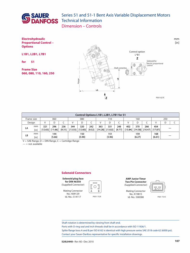
107520L0440 • Rev AE • Dec 2010
Series 51 and 51-1 Bent Axis Variable Displacement MotorsTechnical Information
mm[in]
Shaft rotation is determined by viewing from shaft end. Ports with O-ring seal and inch threads shall be in accordance with ISO 11926/1. Splite flange boss A and B per ISO 6162 is identical with high pressure series SAE J518 code 62 (6000 psi). Contact your Sauer-Danfoss representative for specific installation drawings.
Dimension – Controls
ElectrohydraulicProportional Control – Options
L1B1, L2B1, L7B1
for 51
Frame Size060, 080, 110, 160, 250
Flan
ge
LA
LB
49.0
[1.9
3]
Shaft centerline
P001 827E
Solenoid forElectric proportional control
Control option L*B1
Z
Z
Solenoid Connectors
Solenoid plug facefor DIN 46350
(Supplied Connector)
Mating ConnectorNo.: K09129
Id.-No.: 514117
A B
P001 752E
AMP Junior TimerTwo Pin Connector
(Supplied Connector)
Mating ConnectorNo.: K19815
Id.-No.: 508388
2 1
P001 751E
ezisemarF 060 080 011 061 052
ngiseD V D C V D C V D C V D C V D C
ALmm 123
]36.21[692
]66.11[632
]13.9[443
]55.31[023
]06.21[242
]25.9[363
]82.41[133
]20.31[842
]77.9[204
]48.51[073
]85.41[662
]74.01[454
]78.71[—AL
]ni[123
]36.21[692
]66.11[632
]13.9[443
]55.31[023
]06.21[242
]25.9[363
]82.41[133
]20.31[842
]77.9[204
]48.51[073
]85.41[662
]74.01[454
]78.71[—
BLmm 441
]66.5[051
]09.5[151
]69.5[951
]72.6[861
]16.6[—BL
]ni[441
]66.5[051
]09.5[151
]69.5[951
]72.6[861
]16.6[—
egnalf-egdirtraC=C,egnalf-NID=D,egnalf-EAS=Velbaliavaton=—
Control Options L1B1, L2B1, L7B1 for 51
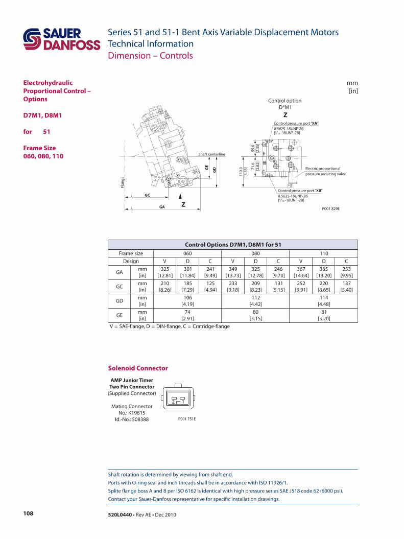
108 520L0440 • Rev AE • Dec 2010
Series 51 and 51-1 Bent Axis Variable Displacement MotorsTechnical Information
Shaft rotation is determined by viewing from shaft end. Ports with O-ring seal and inch threads shall be in accordance with ISO 11926/1. Splite flange boss A and B per ISO 6162 is identical with high pressure series SAE J518 code 62 (6000 psi). Contact your Sauer-Danfoss representative for specific installation drawings.
mm[in]
Dimension – Controls
ElectrohydraulicProportional Control – Options
D7M1, D8M1
for 51
Frame Size060, 080, 110
Flan
ge
GC
GA
GDG
E
Shaft centerline
Electric proportional pressure reducing valve
Control pressure port “XA” 0.5625-18UNF-2B[9/16 -18UNF-2B]
Control pressure port “XB” 0.5625-18UNF-2B[9/16 -18UNF-2B]
Z
Control option D*M1
Z
59.6
[2.3
5]71
.6[2
.82]
110.
0[4
.33]
P001 829E
AMP Junior TimerTwo Pin Connector
(Supplied Connector)
Mating ConnectorNo.: K19815
Id.-No.: 508388
2 1
P001 751E
Solenoid Connector
ezisemarF 060 080 011
ngiseD V D C V D C V D C
AGmm]ni[
523]18.21[
103]48.11[
142]94.9[
943]37.31[
523]87.21[
642]07.9[
763]46.41[
533]02.31[
352]59.9[
CGmm]ni[
012]62.8[
581]92.7[
521]49.4[
332]81.9[
902]32.8[
131]51.5[
252]19.9[
022]56.8[
731]04.5[
DGmm]ni[
601]91.4[
211]24.4[
411]84.4[
EGmm]ni[
47]19.2[
08]51.3[
18]02.3[
egnalf-egdirtarC=C,egnalf-NID=D,egnalf-EAS=V
Control Options D7M1, D8M1 for 51
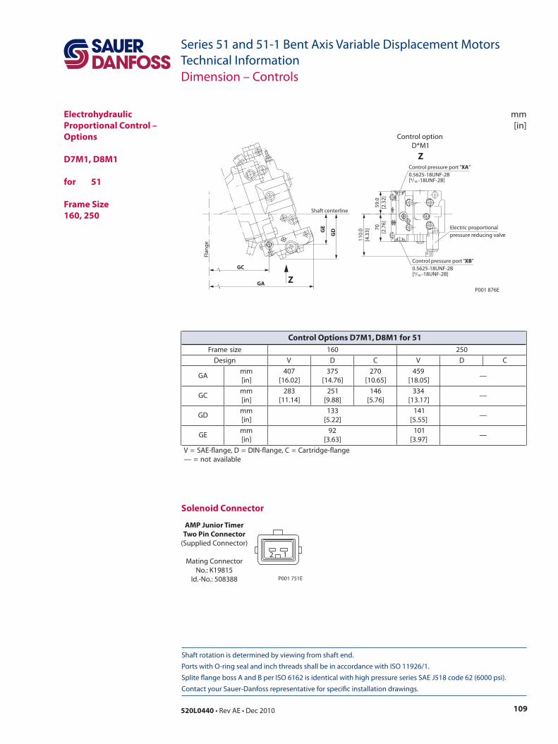
109520L0440 • Rev AE • Dec 2010
Series 51 and 51-1 Bent Axis Variable Displacement MotorsTechnical Information
mm[in]
Shaft rotation is determined by viewing from shaft end. Ports with O-ring seal and inch threads shall be in accordance with ISO 11926/1. Splite flange boss A and B per ISO 6162 is identical with high pressure series SAE J518 code 62 (6000 psi). Contact your Sauer-Danfoss representative for specific installation drawings.
Dimension – Controls
ElectrohydraulicProportional Control – Options
D7M1, D8M1 for 51 Frame Size160, 250
Flan
ge
GC
GA
GDG
E
Shaft centerline
Electric proportional pressure reducing valve
Control pressure port “XA” 0.5625-18UNF-2B[9/16 -18UNF-2B]
Control pressure port “XB” 0.5625-18UNF-2B[9/16 -18UNF-2B]
Z
Control option D*M1
Z
59.0
[2.3
2]70
[2.7
6]
110.
0[4
.33]
P001 876E
AMP Junior TimerTwo Pin Connector
(Supplied Connector)
Mating ConnectorNo.: K19815
Id.-No.: 508388
2 1
P001 751E
Solenoid Connector
ezisemarF 061 052
ngiseD V D C V D C
AGmm]ni[
704]20.61[
573]67.41[
072]56.01[
954]50.81[
—
CGmm]ni[
382]41.11[
152]88.9[
641]67.5[
433]71.31[
—
DGmm]ni[
331]22.5[
141]55.5[
—
EGmm]ni[
29]36.3[
101]79.3[
—
egnalf-egdirtraC=C,egnalf-NID=D,egnalf-EAS=Velbaliavaton=—
Control Options D7M1, D8M1 for 51
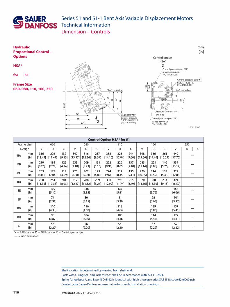
110 520L0440 • Rev AE • Dec 2010
Series 51 and 51-1 Bent Axis Variable Displacement MotorsTechnical Information
Shaft rotation is determined by viewing from shaft end. Ports with O-ring seal and inch threads shall be in accordance with ISO 11926/1. Splite flange boss A and B per ISO 6162 is identical with high pressure series SAE J518 code 62 (6000 psi). Contact your Sauer-Danfoss representative for specific installation drawings.
mm[in]
Dimension – Controls
HydraulicProportional Control – Options
HSA* for 51 Frame Size060, 080, 110, 160, 250
BE
BJ
Flan
ge
BC
BB
BA
BH
BF
58.0
[2.3
]
BG
BD
114
[4.4
7]
Pressure compensatoroverride
Shaft centerline Shaft centerline
P001 828E
Control pressure port “XA” 0.5625-18UNF-2B[9/16 -18UNF-2B]
Control pressure port “X1” 0.5625-18UNF-2B[9/16 -18UNF-2B]
Control pressure port “XB” 0.5625-18UNF-2B[9/16 -18UNF-2B]
Gage port “M7” Control pressure0.5625-18UNF-2B[9/16 -18UNF-2B]Z
Control option HSA*
Z
ezisemarF 060 080 011 061 052
ngiseD V D C V D C V D C V D C V D C
ABmm]ni[
613]54.21[
292]94.11[
232]31.9[
043]73.31[
613]43.21[
732]43.9[
853]01.41[
623]48.21[
442]06.9[
893]66.51[
663]04.41[
162]92.01[
944]07.71[
—ABmm]ni[
613]54.21[
292]94.11[
232]31.9[
043]73.31[
613]43.21[
732]43.9[
853]01.41[
623]48.21[
442]06.9[
893]66.51[
663]04.41[
162]92.01[
944]07.71[
—
BBmm]ni[
012]62.8[
581]92.7[
521]49.4[
332]81.9[
902]32.8[
131]51.5[
252]09.9[
022]56.8[
731]04.5[
382]41.11[
152]88.9[
641]67.5[
433]71.31[
—BBmm]ni[
012]62.8[
581]92.7[
521]49.4[
332]81.9[
902]32.8[
131]51.5[
252]09.9[
022]56.8[
731]04.5[
382]41.11[
152]88.9[
641]67.5[
433]71.31[
—
CBmm]ni[
302]00.8[
971]40.7[
911]96.4[
622]88.8[
202]49.7[
321]58.4[
442]16.9[
212]53.8[
031]11.5[
672]58.01[
442]95.9[
931]84.5[
723]88.21[
—CBmm]ni[
302]00.8[
971]40.7[
911]96.4[
622]88.8[
202]49.7[
321]58.4[
442]16.9[
212]53.8[
031]11.5[
672]58.01[
442]95.9[
931]84.5[
723]88.21[
—
DBmm]ni[
882]53.11[
462]83.01[
402]30.8[
213]72.21[
882]23.11[
902]42.8[
033]99.21[
892]47.11[
612]94.8[
073]65.41[
833]03.31[
332]81.9[
124]95.61[
—DBmm]ni[
882]53.11[
462]83.01[
402]30.8[
213]72.21[
882]23.11[
902]42.8[
033]99.21[
892]47.11[
612]94.8[
073]65.41[
833]03.31[
332]81.9[
124]95.61[
—
EBmm]ni[
031]21.5[
631]53.5[
731]14.5[
541]27.5[
451]60.6[
—EBmm]ni[
031]21.5[
631]53.5[
731]14.5[
541]27.5[
451]60.6[
—
FBmm]ni[
47]19.2[
08]51.3[
18]02.3[
29]36.3[
101]79.3[
—FBmm]ni[
47]19.2[
08]51.3[
18]02.3[
29]36.3[
101]79.3[
—
GBmm]ni[
011]33.4[
611]85.4[
811]46.4[
921]60.5[
731]14.5[
—GBmm]ni[
011]33.4[
611]85.4[
811]46.4[
921]60.5[
731]14.5[
—
HBmm]ni[
89]78.3[
401]01.4[
601]61.4[
411]74.4[
221]18.4[
—HBmm]ni[
89]78.3[
401]01.4[
601]61.4[
411]74.4[
221]18.4[
—
JBmm]ni[
65]02.2[
65]02.2[
65]02.2[
75]22.2[
75]22.2[
—JBmm]ni[
65]02.2[
65]02.2[
65]02.2[
75]22.2[
75]22.2[
—
egnalf-egdirtraC=C,egnalf-NID=D,egnalf-EAS=Velbaliavaton=—
Control Option HSA* for 51
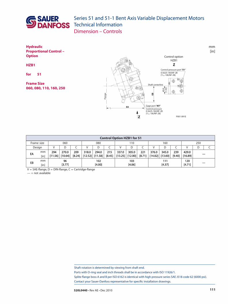
111520L0440 • Rev AE • Dec 2010
Series 51 and 51-1 Bent Axis Variable Displacement MotorsTechnical Information
mm[in]
Shaft rotation is determined by viewing from shaft end. Ports with O-ring seal and inch threads shall be in accordance with ISO 11926/1. Splite flange boss A and B per ISO 6162 is identical with high pressure series SAE J518 code 62 (6000 psi). Contact your Sauer-Danfoss representative for specific installation drawings.
Dimension – Controls
HydraulicProportional Control – Option
HZB1 for 51
Frame Size060, 080, 110, 160, 250
Control pressure port “X1” 0.5625-18UNF-2B[9/16 -18UNF-2B]
Flan
geEA
EB
49.0
[1.9
3]
Shaft centerline
P001 891E
X1
M7
Gage port “M7”Control pressure 0.5625-18UNF-2B[9/16 -18UNF-2B]
Z
Control option HZB1
Z
ezisemarF 060 080 011 061 052
ngiseD V D C V D C V D C V D C V D C
AEmm 492
]65.11[0.072
]46.01[902
]42.8[0.813
]25.21[0.492
]85.11[512
]54.8[0.733
]52.31[0.503
]00.21[122
]17.8[0.673
]28.41[0.543
]06.31[932
]04.9[0.924
]98.61[—AE
]ni[492
]65.11[0.072
]46.01[902
]42.8[0.813
]25.21[0.492
]85.11[512
]54.8[0.733
]52.31[0.503
]00.21[122
]17.8[0.673
]28.41[0.543
]06.31[932
]04.9[0.924
]98.61[—
BEmm 69
]77.3[201
]00.4[301
]60.4[111
]73.4[021
]17.4[—BE
]ni[69
]77.3[201
]00.4[301
]60.4[111
]73.4[021
]17.4[—
egnalf-egdirtraC=C,egnalf-NID=D,egnalf-EAS=Velbaliavaton=—
Control Option HZB1 for 51
Local address:
Sauer-Danfoss GmbH & Co. OHGPostfach 2460, D-24531 NeumünsterKrokamp 35, D-24539 Neumünster, GermanyPhone: +49 4321 871 0Fax: +49 4321 871 122
Sauer-Danfoss ApSDK-6430 Nordborg, DenmarkPhone: +45 7488 4444Fax: +45 7488 4400
Sauer-Danfoss is a global manufacturer and supplier of high-quality hydraulic and electronic components. We specialize in providing state-of-the-art technology and solutions that excel in the harsh operating conditions of the mobile off -highway market. Building on our extensive applications expertise, we work closely with our customers to ensure exceptional performance for a broad range of off -highway vehicles.
We help OEMs around the world speed up system development, reduce costs and bring vehicles to market faster. Sauer-Danfoss – Your Strongest Partner in Mobile Hydraulics.
Go to www.sauer-danfoss.com for further product information.
Wherever off -highway vehicles are at work, so is Sauer-Danfoss.
We off er expert worldwide support for our customers, ensuring the best possible solutions for outstanding performance. And with an extensive network of Global Service Partners, we also provide comprehensive global service for all of our components.
Please contact the Sauer-Danfoss representative nearest you.
Products we off er:
• Bent Axis Motors
• Closed Circuit Axial Piston Pumps and Motors
• Displays
• Electrohydraulic Power Steering
• Electrohydraulics
• Hydraulic Power Steering
• Integrated Systems
• Joysticks and Control Handles
• Microcontrollers and Software
• Open Circuit Axial Piston Pumps
• Orbital Motors
• PLUS+1™ GUIDE
• Proportional Valves
• Sensors
• Steering
• Transit Mixer Drives
Members of the Sauer-Danfoss Group:
Comatrolwww.comatrol.com
Schwarzmüller-Inverterwww.schwarzmueller-inverter.com
Turolla www.turollaocg.com
Hydro-Gear www.hydro-gear.com
Sauer-Danfoss-Daikinwww.sauer-danfoss-daikin.com
Sauer-Danfoss (US) Company2800 East 13th StreetAmes, IA 50010, USAPhone: +1 515 239 6000Fax: +1 515 239 6618
Sauer-Danfoss-Daikin LTD.Shin-Osaka TERASAKI 3rd Bldg. 6F1-5-28 Nishimiyahara, Yodogawa-kuOsaka 532-0004, JapanPhone: +81 6 6395 6066Fax: +81 6 6395 8585
w w w . s a u e r - d a n f o s s . c o m520L0440 • Rev AE • Dec 2010