Embed Size (px)
Citation preview

Arc
hite
ktur
a ko
mpu
teró
w, I
nfor
mat
yka,
sem
.III
Serial Communication
Buses

Arc
hite
ktur
a ko
mpu
teró
w, I
nfor
mat
yka,
sem
.III
Serial Communication
Sending data one bit at one time, sequentially
Serial vs parallel communicationcable cost (or PCB space), synchronization, distance !
speed ?
Improved serial communication technology allows for transfer at higher speeds and is dominating the modern digital technology:
RS232, RS-485, I2C, SPI, 1-Wire, USB, FireWire, Ethernet, Fibre Channel, MIDI, Serial Attached SCSI, Serial ATA, PCI Express, etc.

Arc
hite
ktur
a ko
mpu
teró
w, I
nfor
mat
yka,
sem
.III
RS232, EIA232The Electronic Industries Alliance (EIA) standard RS-232-C (1969)
definition of physical layer (electrical signal characteristics: voltage levels, signaling rate, timing, short-circuit behavior, cable length, etc.)
25 or (more often) 9-pin connector
serial transmission (bit-by-bit)
asynchronous operation (no clock signal)
truly bi-directional transfer (full-duplex)
numerous handshake lines (seldom used)
many protocols use RS232 (e.g. Modbus)

Arc
hite
ktur
a ko
mpu
teró
w, I
nfor
mat
yka,
sem
.III
Voltage LevelsRS-232 standard convert TTL/CMOS-level signals into bipolar voltage levels to improve noise immunity and support long cable lengths
TTL/CMOS (UART) → RS232:
0V = logic zero → +3V…+12V (SPACE)
+5V (+3.3V) = logic one → −3V…−12V (MARK)
Some equipment ignores the negative level and accepts a zero voltage level as the "MARK" state
The "dead area" (−3V ... +3V) may vary, many receivers are sensitive to differentials of 1V
Arc
hite
ktur
a ko
mpu
teró
w, I
nfor
mat
yka,
sem
.III
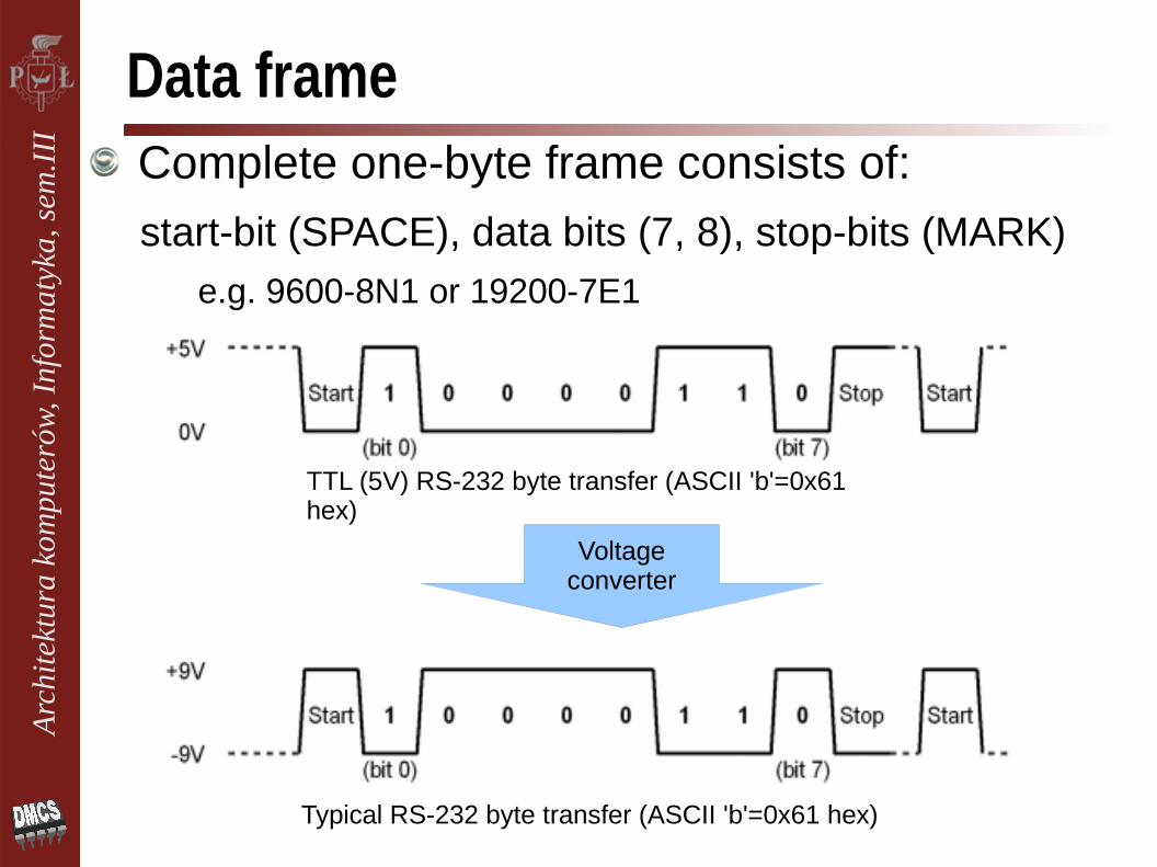
Data frame
Typical RS-232 byte transfer (ASCII 'b'=0x61 hex)
Complete one-byte frame consists of:
start-bit (SPACE), data bits (7, 8), stop-bits (MARK)
e.g. 9600-8N1 or 19200-7E1
TTL (5V) RS-232 byte transfer (ASCII 'b'=0x61 hex)
Voltageconverter

Arc
hite
ktur
a ko
mpu
teró
w, I
nfor
mat
yka,
sem
.III
Data RatesPure EIA RS-232C standard permits data rates up to 19200 bps and cable lengths up to 400 meters (but not both)
Data rates as high as 256kbps (over less than 2 m) are possible
Universal Asynchronous Receiver/Transmitter (UART) – component responsible for fast communication via RS-232
Common 16550 UART incorporates a 16-byte FIFO and is mandatory for communications at speeds above 9600 bps

Arc
hite
ktur
a ko
mpu
teró
w, I
nfor
mat
yka,
sem
.III
DTE and DCEThe RS-232 defines two classes of devices:
data terminal equipment (DTE) – computer (male)
data communication equipment (DCE) – modem (female)
e.g. TD is output line on DTE, but input line on DCE
distinction between DTE&DCE allows to avoid confusion
male chauvinism?

Arc
hite
ktur
a ko
mpu
teró
w, I
nfor
mat
yka,
sem
.III
SignalsComplete RS232 standard define a lot of signals and is fairly complex
Many communications options exist, but only very few are used in practice
CTS Clear To Send [DCE --> DTE]DCD Data Carrier Detected (Tone from a modem) [DCE --> DTE]DCE Data Communications Equipment eg. modemDSR Data Set Ready [DCE --> DTE]DSRS Data Signal Rate Selector [DCE --> DTE] (Not common)DTE Data Terminal Equipment eg. computer, printerDTR Data Terminal Ready [DTE --> DCE]FG Frame Ground (screen or chassis)NC No ConnectionRCk Receiver (external) Clock inputRI Ring Indicator (ringing tone detected)RTS Request To Send [DTE --> DCE]RxD Received Data [DCE --> DTE]SG Signal GroundSCTS Secondary Clear To Send [DCE --> DTE]SDCD Secondary Data Carrier Detected (Tone)[DCE -> DTE]SRTS Secondary Ready To Send [DTE --> DCE]SRxD Secondary Received Data [DCE --> DTE]STxD Secondary Transmitted Data [DTE --> DTE]TxD Transmitted Data [DTE --> DTE]
Arc
hite
ktur
a ko
mpu
teró
w, I
nfor
mat
yka,
sem
.III
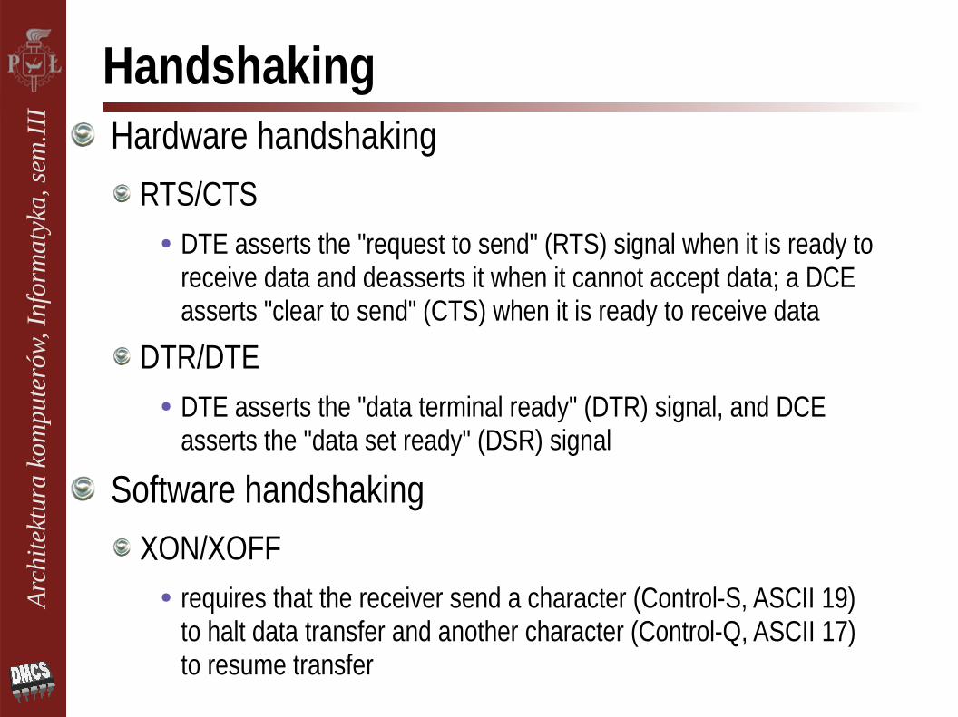
HandshakingHardware handshaking
RTS/CTS● DTE asserts the "request to send" (RTS) signal when it is ready to
receive data and deasserts it when it cannot accept data; a DCE asserts "clear to send" (CTS) when it is ready to receive data
DTR/DTE● DTE asserts the "data terminal ready" (DTR) signal, and DCE
asserts the "data set ready" (DSR) signal
Software handshakingXON/XOFF
● requires that the receiver send a character (Control-S, ASCII 19) to halt data transfer and another character (Control-Q, ASCII 17) to resume transfer

Arc
hite
ktur
a ko
mpu
teró
w, I
nfor
mat
yka,
sem
.III
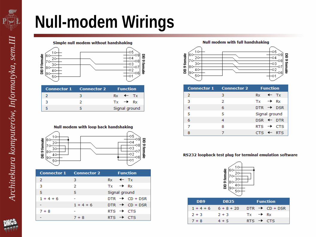
Interface
Sub-D 25, Sub-D 9, RJ45and others
DTE↔DCE – Straight connection
DTE↔DTE – Null-modem (cross-over cable)
DTE – Loopback wiring
Various DB25 to DB9 adapters
Arc
hite
ktur
a ko
mpu
teró
w, I
nfor
mat
yka,
sem
.III
Null-modem Wirings
Arc
hite
ktur
a ko
mpu
teró
w, I
nfor
mat
yka,
sem
.III
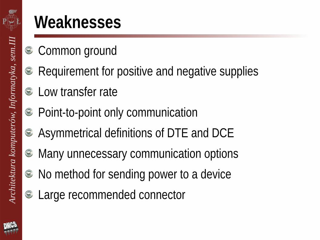
Weaknesses
Common ground
Requirement for positive and negative supplies
Low transfer rate
Point-to-point only communication
Asymmetrical definitions of DTE and DCE
Many unnecessary communication options
No method for sending power to a device
Large recommended connector
Arc
hite
ktur
a ko
mpu
teró
w, I
nfor
mat
yka,
sem
.III
StrengthsRS-232 is being superseded by USB for local communications but ...
USB is more complex (physical layer + protocol + driver) and has no direct analog to the terminal programs for 'raw' communication
Lots of communication protocols can be easily implemented over RS232 (by software or hardware)
Simplicity makes it good for industrial applications where speed is not critical but distance is long
It is available in most of microcontrollers
Lot od cheap RS232<->USB converters
Arc
hite
ktur
a ko
mpu
teró
w, I
nfor
mat
yka,
sem
.III
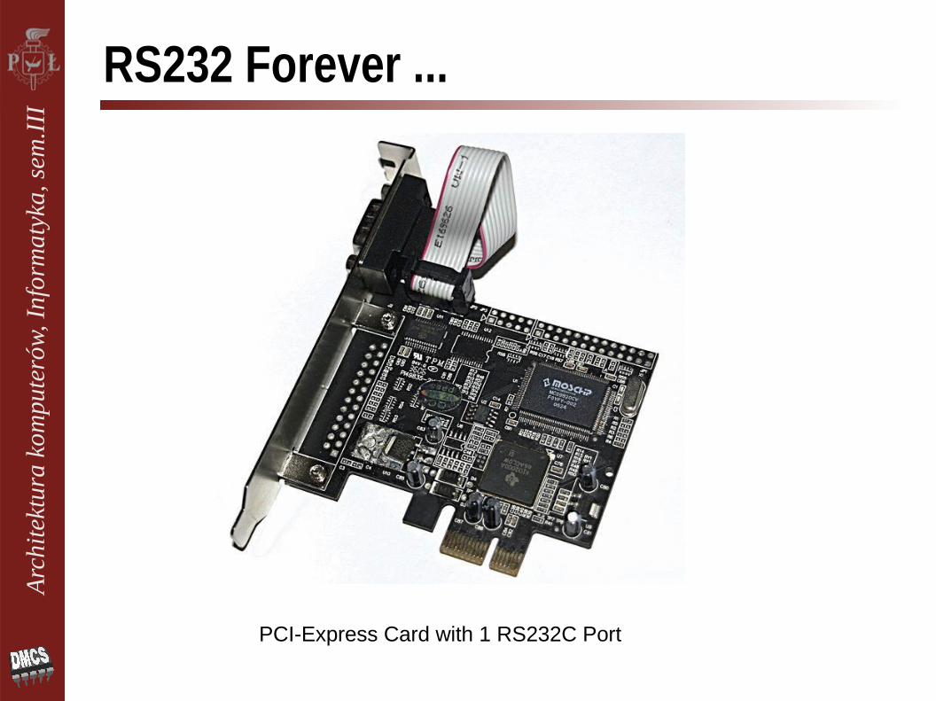
RS232 Forever ...
PCI-Express Card with 1 RS232C Port

Arc
hite
ktur
a ko
mpu
teró
w, I
nfor
mat
yka,
sem
.III
Related StandardsRS-485
a two-wire differential signaling (U+, U-)
half-duplex
multipoint serial connection (inexpensive local networks)
speeds up to 35 Mbit/s (10 m) and 100 kbit/s (1200 m)
Arc
hite
ktur
a ko
mpu
teró
w, I
nfor
mat
yka,
sem
.III
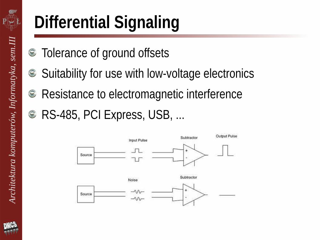
Differential Signaling
Tolerance of ground offsets
Suitability for use with low-voltage electronics
Resistance to electromagnetic interference
RS-485, PCI Express, USB, ...

Arc
hite
ktur
a ko
mpu
teró
w, I
nfor
mat
yka,
sem
.III
USB
Universal Serial Bus (USB) was intended to help retire all legacy varieties of serial and parallel ports (1995)
single standardized interface socket
plug-and-play + hot swapping
providing power to devices (2.5 – 4.5 – 15W)
allowing many standard devices to be used without requiring manufacturer specific
No direct access to physical layer
Complex software+hardwareerror correction, protocols, device classes, etc.

Arc
hite
ktur
a ko
mpu
teró
w, I
nfor
mat
yka,
sem
.III
USB Bus TopologyUSB system: host+interconnect+devices
USB always connects devices with host (master-slave)
Interconnect topology is a tiered star
Arc
hite
ktur
a ko
mpu
teró
w, I
nfor
mat
yka,
sem
.III
Speed
Several data rates:USB 1.x low-speed 1.5 Mb/s
USB 1.x full-speed 12 Mb/s
USB 2.0 high-speed 480 Mb/s
USB 3.0 Super-Speed● 4.8 Gbit/s (600 MB/s)● Full-duplex with additional twisted pair (10 pins in total)● USB 3.1 SuperSpeed+ 10 Gbit/s
The actual throughput attained with real devices is about ⅔ of the maximum theoretical bulk data transfer rate

Arc
hite
ktur
a ko
mpu
teró
w, I
nfor
mat
yka,
sem
.III
Electrical Interface (1.x, 2.0)Four-wire cable, differential signaling, half-duplex,
Twisted pair data cable with 90Ω ±15% impedance
0.0–0.3V Low and 2.8–3.6V High (Low/Full Speed)
±400mV in High Speed (+ protocol to negotiate HS)
Clock tolerance:480.00 Mbit/s ±0.05%
12.000 Mbit/s ±0.25%
1.50 Mbit/s ±1.5%
Arc
hite
ktur
a ko
mpu
teró
w, I
nfor
mat
yka,
sem
.III
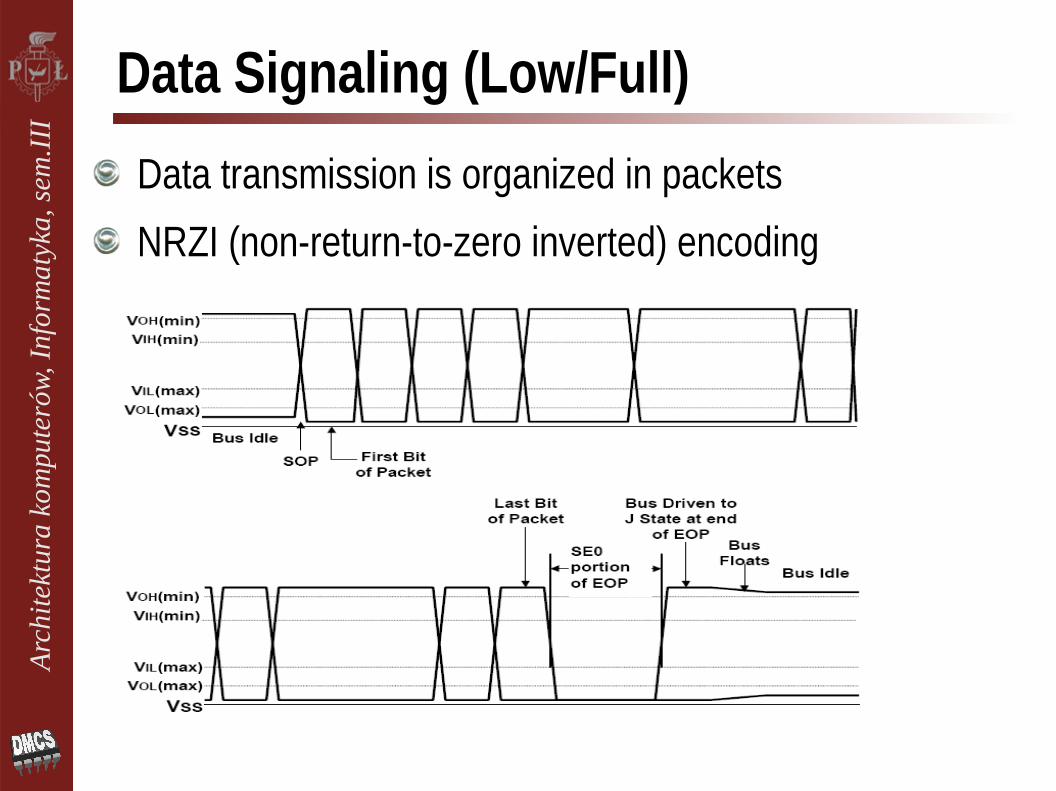
Data Signaling (Low/Full)
Data transmission is organized in packets
NRZI (non-return-to-zero inverted) encoding

Arc
hite
ktur
a ko
mpu
teró
w, I
nfor
mat
yka,
sem
.III
NRZI EncodingBinary code in which "1s" and "0s" are represented with no other neutral or rest condition
Not a self-synchronizing code, synchronization technique must be used to avoid bit slip
"1" is represented by a transition
"0" has no transition

Arc
hite
ktur
a ko
mpu
teró
w, I
nfor
mat
yka,
sem
.III
I²C - Inter-Integrated Circuit I²C (I-squared-C) – Philips (NXP), early 80's (XX)
communication between integrated circuits
only two wires (+ common ground) → small PCB's
multi-master/multi-slave, bidirectional, 8-bit
no strict baud rate requirements (master sends the clock)
7bit or 10bit unique device addressing
simple – hardware or (easy) software implementation

Arc
hite
ktur
a ko
mpu
teró
w, I
nfor
mat
yka,
sem
.III
Highly-integrated TV set
Example of TV set architecture with I2C (historical)
Arc
hite
ktur
a ko
mpu
teró
w, I
nfor
mat
yka,
sem
.III
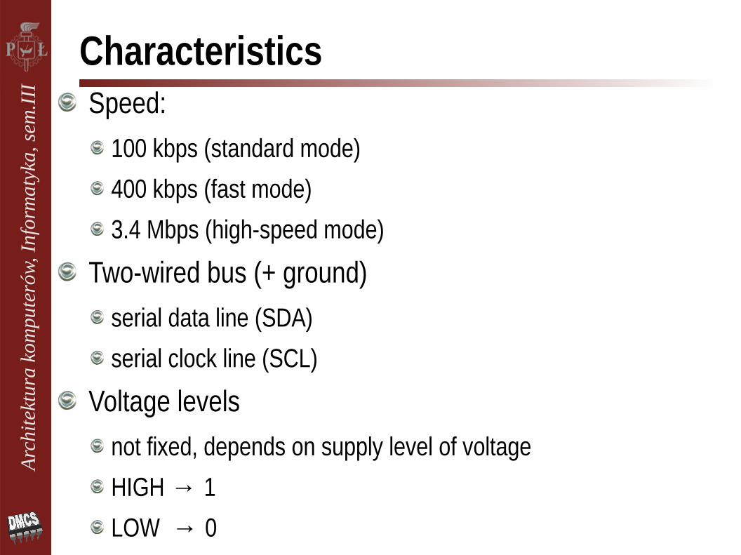
CharacteristicsSpeed:
100 kbps (standard mode)
400 kbps (fast mode)
3.4 Mbps (high-speed mode)
Two-wired bus (+ ground)serial data line (SDA)
serial clock line (SCL)
Voltage levels not fixed, depends on supply level of voltage
HIGH → 1
LOW → 0

Arc
hite
ktur
a ko
mpu
teró
w, I
nfor
mat
yka,
sem
.III
Bit Transfer
Bit transfer is level triggeredSCL = 0↑1 → SDA = valid data
one clock pulse per data bit
stable data during high clocks
data change during low clocks
Arc
hite
ktur
a ko
mpu
teró
w, I
nfor
mat
yka,
sem
.III
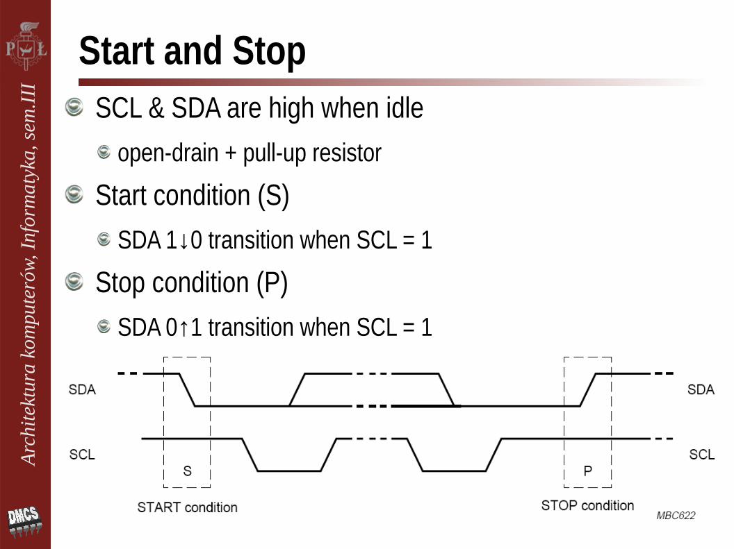
Start and StopSCL & SDA are high when idle
open-drain + pull-up resistor
Start condition (S)SDA 1↓0 transition when SCL = 1
Stop condition (P)SDA 0↑1 transition when SCL = 1
Arc
hite
ktur
a ko
mpu
teró
w, I
nfor
mat
yka,
sem
.III
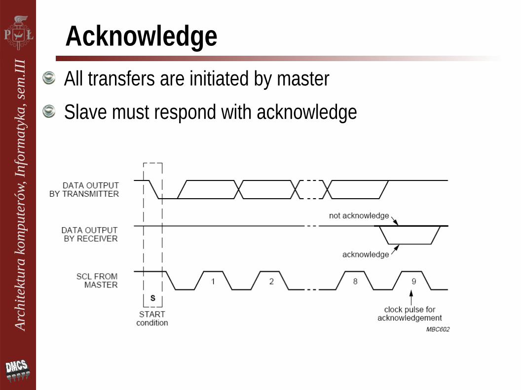
AcknowledgeAll transfers are initiated by master
Slave must respond with acknowledge

Arc
hite
ktur
a ko
mpu
teró
w, I
nfor
mat
yka,
sem
.III
Data Frame
Start + Slave address + Direction Command
Acknowledge from slave
Data (master→slave or slave→master) + Ack.
Stop

Arc
hite
ktur
a ko
mpu
teró
w, I
nfor
mat
yka,
sem
.III
Frame FormatsMaster transmitter
Master receiver
Combined
Arc
hite
ktur
a ko
mpu
teró
w, I
nfor
mat
yka,
sem
.III
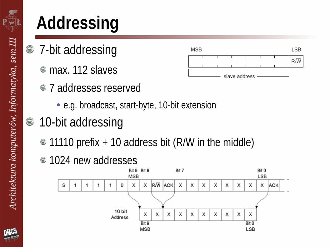
Addressing7-bit addressing
max. 112 slaves
7 addresses reserved● e.g. broadcast, start-byte, 10-bit extension
10-bit addressing11110 prefix + 10 address bit (R/W in the middle)
1024 new addresses
Arc
hite
ktur
a ko
mpu
teró
w, I
nfor
mat
yka,
sem
.III
Closing RemarksElegance of I²C: simplicity & effectiveness
shared bus, reasonable speed, two wires (pins), hotplug
flexible timing: no strict baud rate, clock stretching
arbitration & collision detection in multi-master mode
One of most common communication standard for microcontrollers & integrated circuits
No licensing fees for I²C implementation, but required to obtain I²C slave addresses
Limited Address Space:devices with configurable address
● higher bits indicate model, lower bits - type

Arc
hite
ktur
a ko
mpu
teró
w, I
nfor
mat
yka,
sem
.III
Derivatives
System Management Bus (SMBus)low-bandwidth devices on a PC motherboard
● laptop's battery, temperature, fan, or voltage sensors, configuration data of DDR2, ...
VESA Display Data Channel (DDC)connection between monitor graphics card
● with VGA, DVI, HDMI connectors
Two Wire Interface (TWI)I2C implemented in chips from Atmel
...

Arc
hite
ktur
a ko
mpu
teró
w, I
nfor
mat
yka,
sem
.III
1-Wire®
Registered trademark of Dallas Semiconductor Corp. (now Maxim-Dallas)
Signaling and power using 1 wire (+ ground)
Low-speed ( < 1 kbps)
Long range (up tp 500m)
Low cost
Easy implementation
Typically used to communicate with small inexpensive devices such as digital thermometers and weather instruments
Arc
hite
ktur
a ko
mpu
teró
w, I
nfor
mat
yka,
sem
.III
Available DevicesMemory: EPROM, SRAM, EEPROM, ROM, NV
Temperature Sensors and Switches
1-Wire Interfaces
A-to-D Converters
Timekeeping and Real-Time Clocks
Battery Protectors, Selectors, and Monitors
...

Arc
hite
ktur
a ko
mpu
teró
w, I
nfor
mat
yka,
sem
.III
Powering 1-Wire DevicesWith external supply
Parasite-powered
DS18B20 - Programmable Resolution 1-Wire Digital Thermometer, –55°C to +125°C, ±0.5°C accuracy and user-definable nonvolatile alarm settings

Arc
hite
ktur
a ko
mpu
teró
w, I
nfor
mat
yka,
sem
.III
Device Addressing
There is always only one bus master
Many slave devices can share the same bus
Each device has a unique 64-bit serial number
There are broadcast commands and commands addressed to particular devices
The bus also has an algorithm to recover the address of every device on the bus

Arc
hite
ktur
a ko
mpu
teró
w, I
nfor
mat
yka,
sem
.III
Transaction Sequence
Step 1. Initializationreset pulse
Step 2. ROM Command (followed by any required data exchange)
Search, Read, Match, Skip, Alarm, ...
Step 3. Function Command (followed by any required data exchange)
Read, Write, ReadPowerSupply, ...
Arc
hite
ktur
a ko
mpu
teró
w, I
nfor
mat
yka,
sem
.III
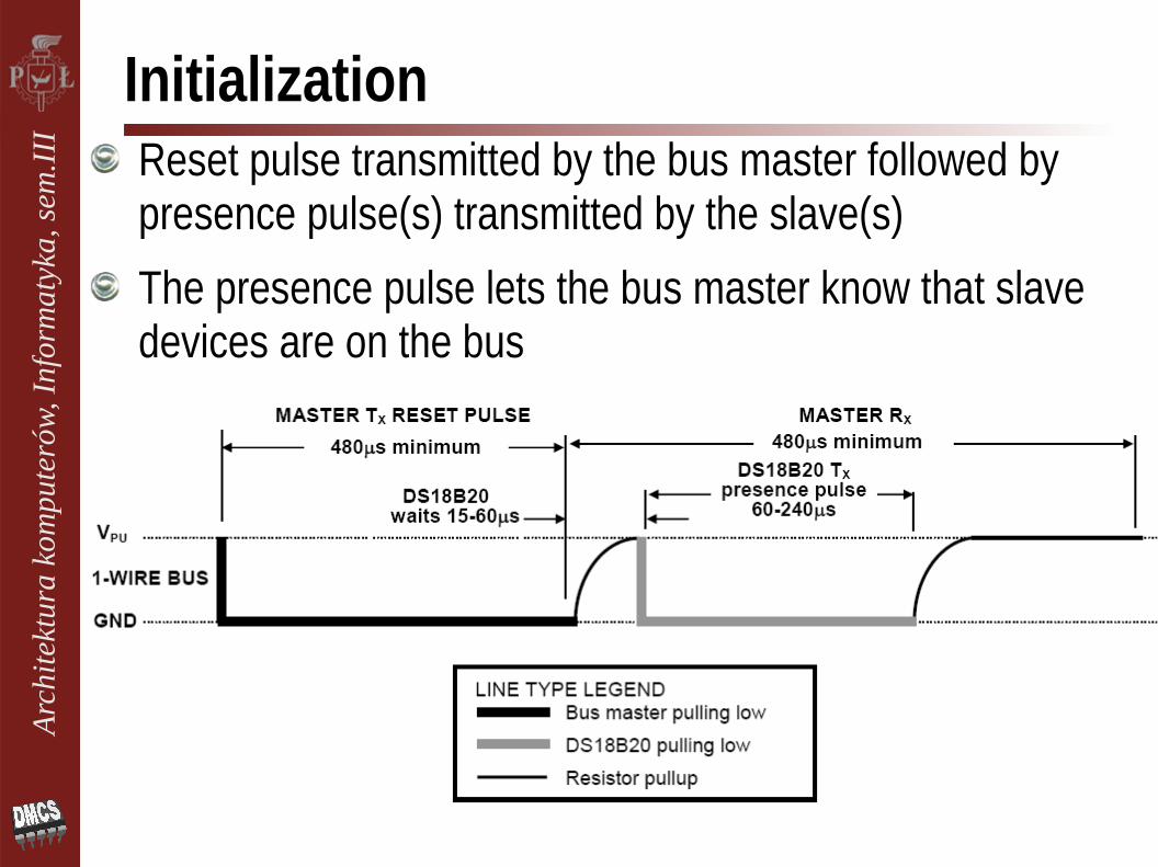
InitializationReset pulse transmitted by the bus master followed by presence pulse(s) transmitted by the slave(s)
The presence pulse lets the bus master know that slave devices are on the bus
Arc
hite
ktur
a ko
mpu
teró
w, I
nfor
mat
yka,
sem
.III
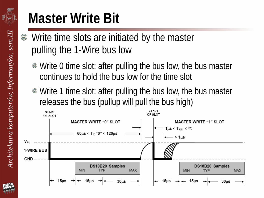
Master Write BitWrite time slots are initiated by the master pulling the 1-Wire bus low
Write 0 time slot: after pulling the bus low, the bus master continues to hold the bus low for the time slot
Write 1 time slot: after pulling the bus low, the bus master releases the bus (pullup will pull the bus high)
Arc
hite
ktur
a ko
mpu
teró
w, I
nfor
mat
yka,
sem
.III
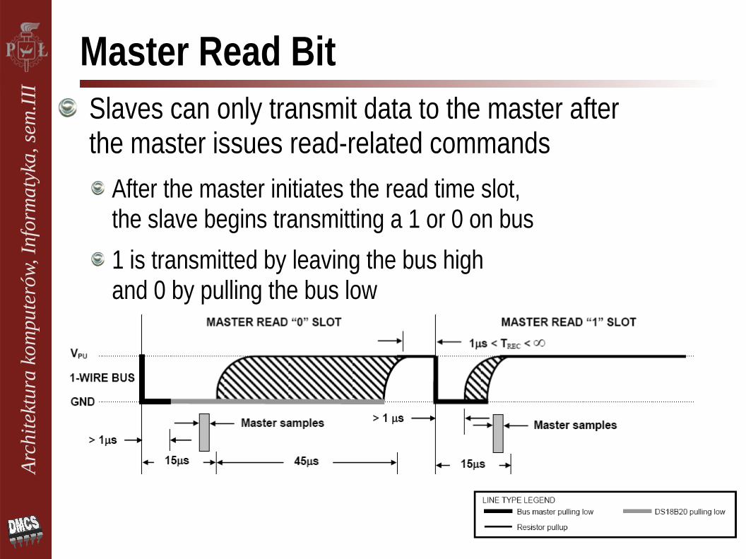
Master Read BitSlaves can only transmit data to the master after the master issues read-related commands
After the master initiates the read time slot, the slave begins transmitting a 1 or 0 on bus
1 is transmitted by leaving the bus high and 0 by pulling the bus low
Arc
hite
ktur
a ko
mpu
teró
w, I
nfor
mat
yka,
sem
.III
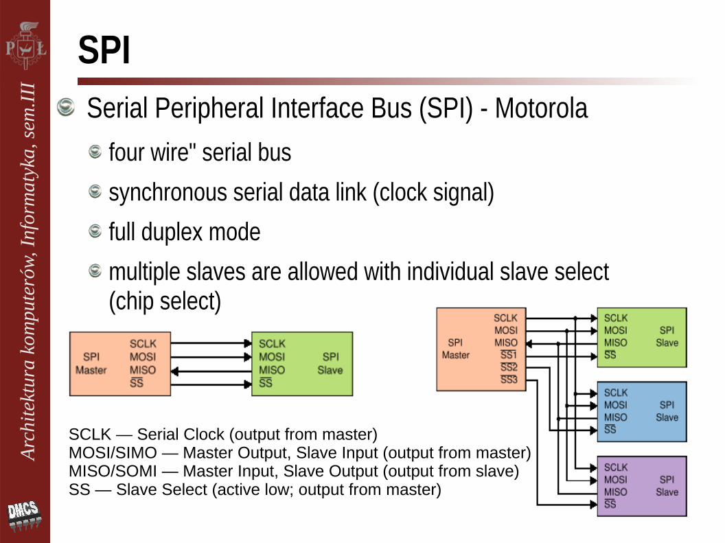
SPISerial Peripheral Interface Bus (SPI) - Motorola
four wire" serial bus
synchronous serial data link (clock signal)
full duplex mode
multiple slaves are allowed with individual slave select (chip select)
SCLK — Serial Clock (output from master)MOSI/SIMO — Master Output, Slave Input (output from master)MISO/SOMI — Master Input, Slave Output (output from slave)SS — Slave Select (active low; output from master)
Arc
hite
ktur
a ko
mpu
teró
w, I
nfor
mat
yka,
sem
.III
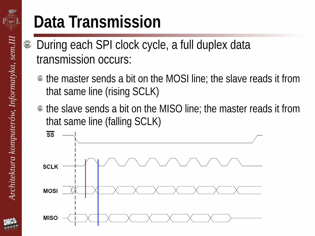
Data TransmissionDuring each SPI clock cycle, a full duplex data transmission occurs:
the master sends a bit on the MOSI line; the slave reads it from that same line (rising SCLK)
the slave sends a bit on the MISO line; the master reads it from that same line (falling SCLK)

Arc
hite
ktur
a ko
mpu
teró
w, I
nfor
mat
yka,
sem
.III
Closing Remarks
Advantages● Full duplex communication● Very fast - higher throughput than I²C● Arbitrary choice of message size and content● Extremely simple hardware interfacing ● No arbitration or associated failure modes● No synchronization problems
Disadvantages● more lines/pins than I²C● No hardware flow control, no slave acknowledgment● limited to a single slave● short distances

![~ a Y R p S x T T i [ g X g U n ¿ Y g Y c i s L · 2017-11-13 · c [ T r U U t ¿ c i U ] h U ¿ g ` T c i U ] Y S T j ` T Y S U r T Y t T ~ U U t L 14 e i U [ W i g U p T " François](https://img.pdfslide.us/doc/110x75/5f5489c62b6e9f01d05352ed/-a-y-r-p-s-x-t-t-i-g-x-g-u-n-y-g-y-c-i-s-l-2017-11-13-c-t-r-u-u-t-c.jpg)


![r Y R G R Y j | W S v R W } r R X S d K U R h Y R g [ J W ... · 9 g ¾ e ^ R W a } n R ¾ e ^ R R u I ] c W T Z T i p [ Y i U x T Z U ~ T i c T Y W U l c T Z U s l [ T14](https://img.pdfslide.us/doc/110x75/5e216c72322dac29f52379e8/r-y-r-g-r-y-j-w-s-v-r-w-r-r-x-s-d-k-u-r-h-y-r-g-j-w-9-g-e-r-w-a-.jpg)