Embed Size (px)
Citation preview

SEPARATOR DESIGN CONSIDERATIONS FOR EFB MICRO-HEV APPLICATIONS
R.W. Pekala, C. La, G. Fraser-Bell, M. Ulrich, S. Gerts, D. Trueba, and R. Waterhouse
September 28, 2012

OUTLINE
2
Extended Flooded Batteries (EFB) Acid Stratification
Mitigation Approaches Current density Rib design Fiber mat Mixing
Electrical resistance Palico vs. CCA Boiled vs. soak Temperature
Separator design considerations Composition Pore size distribution Tortuosity
Future approaches Gels Fibers Foams

ACID STRATIFICATION
3
Positive electrode: PbO2 + H2SO4 + 2H+ + 2e- ↔ PbSO4 + 2H2ONegative electrode: Pb + H2SO4 ↔ PbSO4 + 2H+ + 2e-
On discharge: Dilute, lower density acid produced at electrodes. Rises in laminar flow without mixing with bulk electrolyte.
On charge: Concentrated, higher density acid produced at electrodes. Falls in laminar flow without mixing.

APPROACHES TO REDUCED STRATIFICATION
4
Improve current density uniformity Grid design: heavier, more grid strands at bottom. Tab location and design: Reduce distance to tab. Increased, or graduated, separator resistance.
Disrupt convection Glass mat on Positive electrode. Rib design that disrupts laminar flow on electrode surface and encourage electrolyte mixing. AGM
Promote electrolyte mixing Move electrolyte by pumping or gas lift

STRATIFICATION: SEPARATOR RESISTANCE
5
Increased separator resistance would result in more uniform current density, but at a cost of reduced efficiency and CCA performance.

ANTI‐STRATIFICATION RIB DESIGNS
6

THE PALICO SYSTEM
7
The Palico sends a 83 msec pulse of +100/-100 mA through the current delivery electrodes. It then senses the voltage response to the current at the voltage sensing electrodes.
Palico Test BathPalico Low Resistance Measuring System

SEPARATOR GEOMETRY – ER MODEL
8
A model was developed to relate separator profile/geometry to its electrical resistance as measured on the Palico system.
Laboratory ER measurements are typically performed after boiling separator in DI water for 10 min. followed by a 20 min. acid soak
Schematic showing the approach used by Palico for measuring separator resistance. The separator resistance is the total resistance between the sets of voltage-sensing electrodes with, and without, the separator.

US SEPARATOR ‐‐‐ SIO2/PE = 2.3 VS 2.6
9

ER MEASUREMENT RESULTS
10
Resistance increased smoothly for all test articles as the bath resistance increased.

RELATIVE RESISTANCE VS. TEMPERATURE
11
Except for the perforated plastic “standard”, all separators and the bath follow the same relative resistance behavior as the literature values (Bode, Lead Acid Batteries.)

LIMITATIONS OF PALICO TEST MEASUREMENTS
12
Current densities: Palico separator ER test: (100ma)/(32.3cm²) = 3.1 ma/cm² Battery Impedance Tester: (150ma)/(2200cm²) = 0.068 ma/cm² Cold crank test: (680000ma)/(2200cm²) = 309 ma/cm²
Test temperatures: Palico separator ER test: 27°C Battery Impedance Tester: room temperature (20-25°C) Cold crank test: -18°C
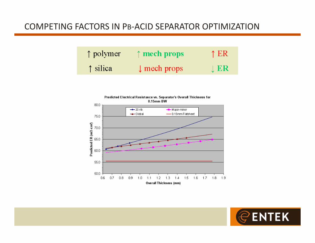
COMPETING FACTORS IN PB‐ACID SEPARATOR OPTIMIZATION
13

SEPARATOR ER
14
Separator resistance is a function of pore structure and composition.
Resistance of electrolyte within a porous structure:

PORE STRUCTURE
15
The pore structure of PE/silica separator is characterized by its heterogeneity: Hydrophilic silica aggregates of different sizes Hydrophobic polyethylene fibrils Differences in structure between surface (polymer-rich) and bulk (silica-rich) Not all pore volume is filled with electrolyte
Total pore volume: Water accessible pore volume:
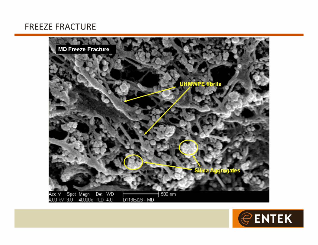
FREEZE FRACTURE
16
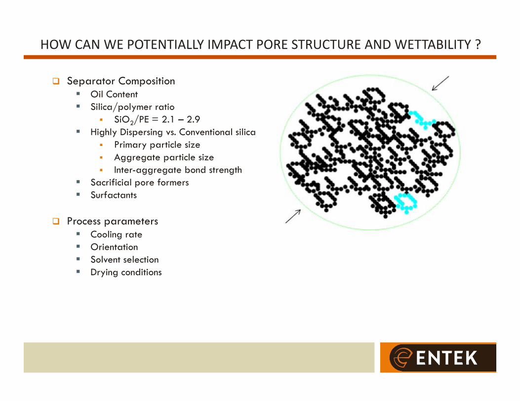
HOW CAN WE POTENTIALLY IMPACT PORE STRUCTURE AND WETTABILITY ?
17
Separator Composition Oil Content Silica/polymer ratio
SiO2/PE = 2.1 – 2.9 Highly Dispersing vs. Conventional silica
Primary particle size Aggregate particle size Inter-aggregate bond strength
Sacrificial pore formers Surfactants
Process parameters Cooling rate Orientation Solvent selection Drying conditions

HG POROSIMETRY DATA AS A FUNCTION OF SIO2/PE RATIO
18

HG POROSIMETRY DATA – DIFFERENT SILICA TYPES
19

CHARACTERIZATION – WATER POROSITY & BOILED ER
20
At the same SiO2:PE ratio, the LDS separator shows slightly lower water porosity compared to the HDS separator.
The electrical resistance for the LDS separator is about 27% higher than the HDS separator at the same SiO2:PE ratio.

HG POROSIMETRY DATA ‐‐‐ ENTEK VS. COMPETITOR
21
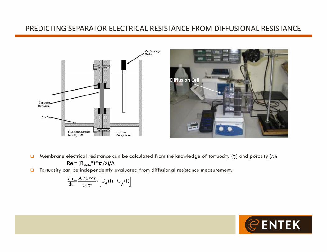
PREDICTING SEPARATOR ELECTRICAL RESISTANCE FROM DIFFUSIONAL RESISTANCE
22
Membrane electrical resistance can be calculated from the knowledge of tortuosity ( ) and porosity ( ):
Tortuosity can be independently evaluated from diffusional resistance measurement:

PREDICTING SEPARATOR ELECTRICAL RESISTANCE FROM DIFFUSIONAL RESISTANCE
23
Resistance to electrolyte diffusion through membranes decreases as more silica is added to the formula.
Tortuosity decreases as more silica is loaded in the separator.
The predicted electrical resistivity values agree fairly well with the measured boiled electrical resistivity values (difference is 6% or less).

SEPARATOR RESISTIVITY VS. TORTUOSITY
24
Separator electrical resistivity can be reduced by reducing tortuosity and/or increasing porosity
ALTERNATIVE APPROACHES
25
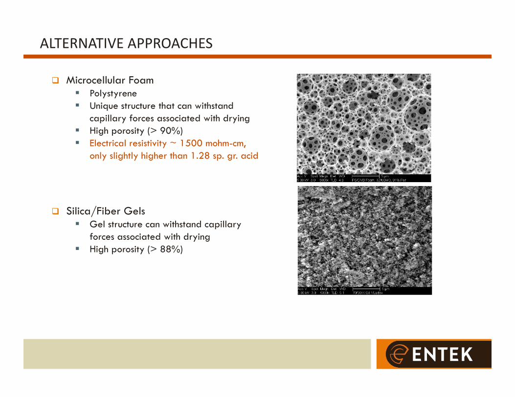
Microcellular Foam Polystyrene Unique structure that can withstand
capillary forces associated with drying High porosity (> 90%) Electrical resistivity ~ 1500 mohm-cm,
only slightly higher than 1.28 sp. gr. acid
Silica/Fiber Gels Gel structure can withstand capillary
forces associated with drying High porosity (> 88%)
SUMMARY
26
The principal need for separators in EFB applications is for lower ER. Cold crank Warm crank at partial state of charge
Separator ER is determined by pore structure Wetted porosity Tortuosity
Pore structure is the result of Composition Manufacturing process
New pore structures may be required for EFB Microcellular foams Filler/fiber composites

ENTEK Separators 250 N Hansard Ave Lebanon, OR 97355 USA www.entek.com