Embed Size (px)
Citation preview

CIVIL AVIATION PUBLICATION
OPS 05
ELECTRONIC FLIGHT BAG (EFB)
INDEX

This Page Intentionally Left Blank
CIVIL AVIATION PUBLICATION
OPS 05 i 25 March 2021
OPS 05
ELECTRONIC FLIGHT BAG (EFB)
INDEX Section Title Page No. 1. Introduction ...................................................................................................................... 1 1.1 General .............................................................................................................................. 1 1.2 Background ........................................................................................................................ 1 1.3 Approval Requirements..................................................................................................... 1 2. Applicability ...................................................................................................................... 2 3. References ........................................................................................................................ 2 4. Glossary of Terms ............................................................................................................ 2 5. System Description and Classification of EFB Systems ................................................... 5 5.1 EFB System Hardware ...................................................................................................... 5 5.1.1 Portable EFB ...................................................................................................................... 5 5.1.2 Installed EFB ...................................................................................................................... 6 5.2 Software Applications for EFB Systems ............................................................................. 6 5.2.1 Type A ............................................................................................................................... 7 5.2.2 Type B ................................................................................................................................ 7 5.2.2.1 Airport Moving Map Display (AMMD) Application with Own-ship Position .................... 7 5.2.3 Miscellaneous (Non-EFB) Software Applications .............................................................. 8 6. Hardware and Software Processes ................................................................................. 8 6.1 Airworthiness Approval ..................................................................................................... 8 6.1.1 Hardware Airworthiness Approval .................................................................................... 9 6.1.1.1 Installed Resources ............................................................................................................ 9 6.1.1.1.1 Mounting Device ............................................................................................................... 9 6.1.1.1.2 Characteristics and Placement of the EFB Display .......................................................... 10 6.1.1.1.3 Power Source................................................................................................................... 11 6.1.1.1.4 EFB Data Connectivity ..................................................................................................... 12 6.1.1.1.5 Connecting Cables ........................................................................................................... 12 6.1.1.2 Installed EFB .................................................................................................................... 13 6.1.2 Certification Documentation ........................................................................................... 13 6.1.2.1 Aircraft Flight Manual ...................................................................................................... 13 6.1.2.2 Guidelines for EFB Software Application Developers (Installed EFB & Resources) ........ 14 6.1.2.3 Guidelines for EFB System Suppliers (Installed Resources for Portable EFBs) ............... 14 6.2 Operational Assessment.................................................................................................. 15 6.2.1 Hardware Operational Assessment................................................................................. 15 6.2.1.1 Electromagnetic Interference (EMI) Demonstrations ..................................................... 15 6.2.1.1.1 PED Non-interference Compliance Test Method ............................................................ 15 6.2.1.1.2 Additional T-PED Non-interference Compliance Test Method ....................................... 16 6.2.1.2 Batteries .......................................................................................................................... 17
CIVIL AVIATION PUBLICATION
OPS 05 ii 25 March 2021
6.2.1.3 Power Source................................................................................................................... 17 6.2.1.4 Environment Testing ....................................................................................................... 18 6.2.1.5 Display Characteristics .................................................................................................... 18 6.2.1.6 Viewable Stowage ........................................................................................................... 19 6.2.2 Software Operational Assessment .................................................................................. 19 6.2.2.1 Type A Software Applications ......................................................................................... 19 6.2.2.2 Type B Software Applications .......................................................................................... 19 6.2.2.3 Miscellaneous (Non EFB) Software Applications ............................................................ 19 7. Operational Assessment Process ................................................................................... 20 7.1 Role of the EFB System Supplier ..................................................................................... 20 7.2 Risk assessment for EFB Systems .................................................................................... 21 7.2.1 General ............................................................................................................................ 21 7.2.2 Assessing and Mitigating the Risks .................................................................................. 21 7.3 Changes to EFB ................................................................................................................ 23 7.4 Dispatch Considerations .................................................................................................. 23 7.4.1 Dispatch with Inoperative EFB Elements ........................................................................ 24 7.5 Human Factor Assessment .............................................................................................. 24 7.6 Specific Considerations for Mass and Balance and Performance Applications .............. 24 7.7 Flight Crew Operating Procedures .................................................................................. 25 7.7.1 Procedures for Using EFB Systems with other Flight Crew Compartment Systems ....... 25 7.7.2 Flight Crew Awareness of EFB Software/Database Revisions ......................................... 25 7.7.3 Procedures to Mitigate and/or Control Workload .......................................................... 25 7.7.4 Defining Flight Crew Responsibilities for Performance Calculations .............................. 25 7.8 Periodic Monitoring ......................................................................................................... 25 7.9 EFB System Security ........................................................................................................ 26 7.10 Electronic Signatures ....................................................................................................... 27 7.11 Role of the EFB Administrator ......................................................................................... 28 7.11.1 The EFB Policy and Procedures Manual .......................................................................... 29 7.12 EFB System Maintenance ................................................................................................ 29 7.13 Flight Crew Training ......................................................................................................... 30 7.14 Operational Evaluation Test ............................................................................................ 31 7.14.1 Applications Replacing Paper Products with an Initial Retention of Paper Back-up ...... 31 7.14.2 Applications Replacing Paper Products without Paper Back-up ..................................... 32 7.15 Final Operational report .................................................................................................. 32 8. Approval Process ............................................................................................................ 33 8.1 General ............................................................................................................................ 33 8.2 Process ............................................................................................................................. 33 9. Surveillance (All Operators) ........................................................................................... 35 Appendices Appendix 1 Examples of “Type A” Software Applications......................................................... APP 1-1 Appendix 2 Examples of “Type B” Software Applications ........................................................ APP 2-1 Appendix 3 Process for the Classification of Software Applications ......................................... APP 3-1

CIVIL AVIATION PUBLICATION
OPS 05 iii 25 March 2021
Appendix 4 Human Machine Interface Assessment and Human Factors Considerations ........ APP 4-1 Appendix 5 Flight Crew Training ................................................................................................ APP 5-1 Appendix 6 Software Application Documentation .................................................................... APP 6-1 Appendix 7 EFB Policy & Procedures Manual ........................................................................... APP 7-1 Appendix 8 Airport Moving Map Display Application with Own Ship Position ........................ APP 8-1
Appendix 9 Example of Final Operational Report ..................................................................... APP 9-1
Appendix 10 Power Supply Considerations for Portable EFBs .................................................. APP 10-1
Appendix 11 Considerations for Rapid Depressurisation Test .................................................. APP 11-1
Appendix 12 Additional Safety Considerations ......................................................................... APP 12-1

CIVIL AVIATION PUBLICATION
OPS 05 iv 25 March 2021
This Page Intentionally Left Blank
CIVIL AVIATION PUBLICATION
OPS 05 1 25 March 2021
1. INTRODUCTION 1.1 General
This Civil Aviation Publication (CAP) provides information and CAA-B policy regarding the acceptable method of compliance for the certification, airworthiness and operational approval for an Electronic Flight Bag (EFB) aircraft computing devices. The information is primarily designed for the initial application from a Bahamian operator without EFB experience. However, each application will be processed according to the type of EFB, previous experience and quality of documentation.
Whilst the information in this CAP is comprehensive, the application process is relatively straight forward provided the operator provides the training, procedures and necessary precautions.
1.2 Background One of the major motivators for using EFB is to reduce or eliminate the need for paper and other reference material in the cockpit. EFB systems may be approved for use in conjunction with or replace some of the hard copy materials that pilots typically carry in their flight bags. EFB can electronically store and retrieve documents required for flight operations, such as the general operations manual, minimum equipment list, operations specification, and control documents. The use of EFBs was initially intended to cover an alternative method of storing, retrieving, and using the manuals and information required to be on board by the applicable operational requirements. Subsequent technical development has led to potentially hosting on EFBs even applications using computational software (e.g. for performances), databases (e.g. digital navigation data) or real-time data coming from the avionics (e.g. Airport Moving Map Display). CAP 06 no longer includes a Type C software application classification as a potential EFB application. The policy is that any non-Type A (please refer to paragraph 5.2.1) or non-Type B (please refer to paragraph 5.2.2) software application, unless it is miscellaneous (non-EFB) application, should undergo a full airworthiness approval and so become a certified avionics function. A non-exhaustive list of examples of Type A and B applications is provided in Appendices 1 and 2.
1.3 Approval Requirements
(a) Operators of General Aviation aeroplanes (CAR OPS 2A Part I only) and helicopters (CAR OPS 2H) with a portable EFB are required to complete a declaration of compliance (Form OPS 012).
(b) Operators of General Aviation aeroplanes (CAR OPS 2A Part I only) and helicopters (CAR OPS 2H) with installed EFBs must meet of the requirements for approval using application Form OPS 011.
(c) Operators of General Aviation aeroplanes (CAR OPS 2A Part II) require CAA-B approval using application Form OPS 011; and

CIVIL AVIATION PUBLICATION
OPS 05 2 25 March 2021
(d) AOC Holders require CAA-B approval using application Form OPS 011. An operator of an aeroplane with a portable EFB as described in (a) above, shall not employ electronic navigation data products that have been processed for application in the air and on the ground unless the CAA-B accepts the operator declaration. An operator of an aeroplane as described in (b), (c) and (d) above, shall not employ electronic navigation data products that have been processed for application in the air and on the ground unless the CAA-B, as the State of the Operator, has approved their use. The operator’s procedures for ensuring that the process applied and the products delivered must meet acceptable standards of integrity and that the products are compatible with the intended function of the equipment that will use them. Operators shall also implement procedures that ensure the timely distribution and insertion of current and unaltered electronic navigation data to all aeroplanes that require it.
2. APPLICABILITY
This CAP is applicable to;
(a) Commercial Air Transport operators by aeroplane or by helicopter; and (b) CAR OPS 2A, Part I and Part II aeroplanes; and (c) CAR OPS 2H helicopters.
3. REFERENCES
This CAP is based on the following publications which have been accepted as defining references on this subject. (a) CAR OPS 1.873 for AOC holders;
(b) CAR OPS 2A.530 and 2H.509 for General Aviation operators;
(c) FAA AC 120-76D; (d) EASA AMC 20-25.
4. GLOSSARY OF TERMS
Aircraft Administrative Communications (AAC) AAC data link receive/transmit information that includes, but is not limited to, the support of applications identified in Appendices 1 and 2 of this CAP. Aircraft Administrative Communications (AAC) are defined by ICAO as communications used by aeronautical operating agencies related to the business aspects of operating their flights and transport services.
CIVIL AVIATION PUBLICATION
OPS 05 3 25 March 2021
Airport Moving Map Display (AMMD) A software application displaying airport maps and using a navigation source to depict the aircraft current position on this map while on ground. Consumer device Electronic equipment primarily intended for non-aeronautical use. Controlled Portable Electronic Device (C-PED) A controlled PED is a PED subject to administrative control by the operator using it. This will include, inter alia, tracking the allocation of the devices to specific aircraft or persons and ensuring that no unauthorised changes are made to the hardware, software, or databases. Data connectivity for EFB systems Data connectivity for EFB system supports either uni- or bi-directional data communication between the EFB and other aircraft systems (e.g. avionics). Direct interconnectivity between EFBs or direct connectivity between EFBs and ground systems as with T-PED (e.g. GSM, Bluetooth) are not covered by this definition. Electronic Flight Bag (EFB) An information system for flight deck crew members which allows storing, updating, delivering, displaying, and/or computing digital data to support flight operations or duties. EFB administrator An EFB administrator is a person appointed by the operator, held responsible for the administration of the EFB system within the company. The EFB administrator is the primary link between the operator and the EFB system and software suppliers. EFB host platform When considering an EFB system, the EFB host platform is the equipment (i.e. hardware) in which the computing capabilities and basic software (e.g. operating system, input/output software) reside. EFB risk assessment and mitigation A process that considers an EFB system, its software applications, and its integration inside a specific aircraft, to identify the potential malfunctions and failure scenarios, analyse their operational repercussions, and, if necessary, propose mitigation means. EFB software application Software installed on an EFB system that allows specific operational functionality.
CIVIL AVIATION PUBLICATION
OPS 05 4 25 March 2021
EFB system An EFB system comprises the hardware (including any battery, connectivity provision, I/O devices) and software (including databases) needed to support the intended EFB function(s). EFB system supplier The company responsible for developing, or for having developed, the EFB system or part of it. The EFB system supplier is not necessarily a host platform or aircraft manufacturer. Minor failure conditions Failure conditions which would not significantly reduce aeroplane safety, and which involve crew actions that are well within their capabilities. Minor failure conditions may include, for example, a slight reduction in safety margins or functional capabilities, a slight increase in crew workload, such as routine flight plan changes, or some physical discomfort to passengers or cabin crew. Mounting device A mounting device is an aircraft certified part which secures portable or installed EFB, or EFB system components. No safety effect Failure conditions that would have no effect on safety: for example, failure conditions that would not affect the operational capability of the aeroplane or increase crew workload. Portable Electronic Device (PED) PEDs are typically consumer electronic devices, which have functional capability for communications, entertainment, data processing, and/or utility. There are two basic categories of PEDs – those with and those without intentional transmitting capability; please refer to ED- 130/RTCA DO-294(). Software application developer The company responsible for developing, or for having developed a particular software application. Transmitting PED (T-PED) PEDs that have intended radio frequency (RF) transmission capabilities. Viewable stowage A device that is secured on the flight crew (e.g. kneeboard) or in/to an existing aircraft part (e.g. suction cups) with the intended function to hold charts or to hold acceptable light mass portable devices (for example an EFB of no more than 1 Kg) viewable to the pilot at her/his required duty station. The device is not necessarily part of the certified aircraft configuration.
CIVIL AVIATION PUBLICATION
OPS 05 5 25 March 2021
5. SYSTEM DESCRIPTION AND CLASSIFICATION OF EFB SYSTEMS
This section is divided into two parts. The first part deals with the host platform (e.g. the hardware and operating system) used to run the EFB software suite. The second part deals with this software suite which includes the EFB applications installed to provide the relevant functionality.
5.1 EFB systems hardware
This CAP defines two possibilities for the hardware of EFB systems: portable and installed. Note: Some States still refer to portable EFB systems as Class 1 or Class 2.
5.1.1 Portable EFB
Definition A portable EFB is a portable EFB host platform, used on the flight deck, which is not part of the certified aircraft configuration. Complementary characteristics - A portable EFB can be operated inside and outside the aircraft. - A portable EFB hosts type A and/or type B EFB software applications. In addition, it may
host miscellaneous (non-EFB) software applications (see 6.2.2.3). - A portable EFB is a portable electronic device (PED).
Note: PEDs are defined as being any kind of electronic device, typically but not limited to consumer electronics, brought on board the aircraft by crew members, passengers, or as part of the cargo and that are not included in the approved aircraft configuration. All equipment that is able to consume electrical energy falls under this definition. The electrical energy can be provided from internal sources as batteries (chargeable or non-rechargeable) or the devices may also be connected to specific aircraft power sources.
- The mass, dimensions, shape, and position of the portable EFB should not compromise
flight safety. - A portable EFB may be provided with aircraft power through a certified power source
(see 6.1.1.1.3). - If mounted, the portable EFB is easily removable from its mounting device or attached to
it, without the use of tools by the flight crew. If mounted, the Appendix or removal does not constitute a maintenance action.
- A portable EFB may be part of a system containing EFB installed resources which are part
of the certified aircraft configuration.
CIVIL AVIATION PUBLICATION
OPS 05 6 25 March 2021
- The installed EFB components are part of the certified aircraft configuration with the intended function to mount (see 6.1.1.1.1) the EFB to the aircraft and/or connect to other systems (see 6.1.1.1.4).
- When a portable EFB is a T-PED, the conditions for use of its transmitting capability are
established in the approved Aircraft Flight Manual (AFM). In absence of information in the AFM, the EFB transmitting capability may be allowed during non-critical phases of the flight (see 6.2.1.1.2).
- Portable EFBs may be used in all phases of the flight if secured to a certified mount or
securely attached to a viewable stowage device in a manner which allows its normal use (see 6.1.1.1.1, 6.1.1.1.2, and 6.2.1.6).
Portable EFBs not meeting the above characteristic, should be stowed during critical phases of the flight. Portable EFBs are controlled PEDs (see paragraph 4.4). Any EFB component that is either not accessible in the flight crew compartment by the flight crew members or not removable by the flight crew, should be installed as ‘certificated equipment’ covered by a Type Certificate (TC), changed TC or Supplemental (S)TC.
5.1.2 Installed EFB
Definition An EFB host platform installed in the aircraft and considered as an aircraft part, covered, thus, by the aircraft airworthiness approval. Complementary characteristics An installed EFB is managed under the aircraft type design configuration. In addition to hosting Type A and B applications, an installed EFB may host certified applications, provided the EFB meets the certification requirements for hosting such applications, including assurance that the non-certified software applications do not adversely affect the certified application(s). For example, a robust partitioning mechanism is one possible means to ensure the independence between certified applications and the other types of applications.
5.2 Software Application For EFB Systems
The functionality associated with the EFB system depends, in part, upon the applications loaded on the host platform. The classification of the applications, based on respective safety effects, is intended to provide clear divisions among such applications and, therefore, the assessment process applied to each. Appendices 1 and 2 provide support regarding the classification of traditional EFB software applications. They may be used for justifying a classification provided that the application does not feature design or functional novelties introducing new ways of interaction or unusual procedures.
CIVIL AVIATION PUBLICATION
OPS 05 7 25 March 2021
If an application is not listed in the Appendices or presents a high degree of novelty, the classification should be established using the definitions provided and the guidance in Appendix 3. For the purpose of the following definitions, ‘malfunction or misuse’ means any failure, malfunction of the application, or design-related human errors that can be reasonably expected in service.
5.2.1 Type A
Definition Type A applications are EFB applications whose malfunction or misuse have no safety effect. Complementary characteristics Type A applications: (a) may be hosted on either portable or installed EFBs; (b) do not require any approval (see paragraph 6.2.2.1) and should follow guidance provided
in Appendix 4, paragraph 2. Note: Examples of Type A applications can be found in Appendix 1.
5.2.2 Type B
Definition
Type B applications are applications: (a) whose malfunction or misuse are limited to a minor failure condition; (b) and which do neither substitute nor duplicate any system or functionality required by
airworthiness regulations, airspace requirements, or operational rules. Complementary characteristics Type B applications: (a) may be hosted on either portable or installed EFBs; (b) require an operational assessment as described in paragraph 6.2.2.2; and (c) do not require an airworthiness approval. Note: Examples of Type B applications can be found in Appendix 2.
5.2.2.1 Airport Moving Map Display (AMMD) application with own-ship position
AMMD with own-ship position is a Type B application that is subject to the specific conditions described in Appendix 8 of this CAP.
CIVIL AVIATION PUBLICATION
OPS 05 8 25 March 2021
5.2.3 Miscellaneous (non-EFB) software applications
Miscellaneous software applications are non-EFB applications, supporting function(s) not directly related to operations conducted by the flight crew on the aircraft.
6. HARDWARE AND SOFTWARE PROCESSES
The table below provides a summary of the different processes presented in this chapter.
EFB constituent
Portable EFB paragraph 5.1.1 Installed EFB paragraph 5.1.2
Assessment Records or approvals
Assessment Records or approvals
Hardware EFB Installed resources mounting device
Airworthiness process and approval paragraph 6.1.1.1
Airworthiness process and approval paragraph 6.1.1.1
EFB host platform Evaluation paragraph 6.2.1
As a minimum, operations Manual amended as required
Airworthiness process and approval paragraph 6.1.1.2
Software
Miscellaneous software paragraph 6.2.2.3
Operator evaluation paragraph6.2.2.3
Operation s Manual amended as required
Operator evaluation paragraph 6.2.2.3
Operation s Manual amended as required
Software Type A paragraph5.2.1
Operator evaluation paragraph6.2.2.1
Operation s Manual amended as required
Operator evaluation paragraph6.2.2.1
Operation s Manual amended as required
Software Type B paragraph5.2.2
Evaluation paragraph6.2.2.2
As a minimum, operations Manual amended as required
Evaluation paragraph6.2.2.2
As a minimum, operations Manual amended as required
6.1 Airworthiness approval
The airworthiness approval is necessary for installed EFB systems (see paragraph 5.1.2), as well as EFB installed resources and mounting device. A portable EFB device does not require an airworthiness approval but its presence and use in the cockpit needs to be evaluated (see paragraph 6.2.1).
CIVIL AVIATION PUBLICATION
OPS 05 9 25 March 2021
6.1.1 Hardware airworthiness approval 6.1.1.1 Installed resources
Installed resources are the input/output components external to the EFB host platform itself, such as an installed remote display, a control device (e.g. a keyboard, pointing device, switches, etc.) or a docking station.
The installed resources should be dedicated to EFB functions only, or in the case of use of resources shared with avionics, this possibility shall be part of the approved type design. It should be demonstrated, using the appropriate level of assessment, that the integration in the aircraft of the EFB and the EFB software applications does not jeopardise the compliance of the aircraft installed systems and equipment (including the shared resources) to airworthiness requirements such as EASA CS 25.1302 or 25.1309 or FAA equivalent.
Installed resources require an airworthiness approval.
6.1.1.1.1 Mounting device
The mounting device (or other securing mechanism) attaches or allows mounting of the EFB system. The EFB system may include more than one mounting device if it consists of separate items (e.g. one docking station for the EFB host platform and one cradle for the remote display). The mounting device should not be positioned in such a way that it obstructs visual or physical access to aircraft controls and/or displays, flight crew ingress or egress, or external vision. The design of the mounting device should allow the user easy access to any item of the EFB system, even if stowed, and notably to the EFB controls and a clear view of the EFB display while in use. The following design practices should be considered: (a) The mounting device and associated mechanisms should not impede the flight crew in
the performance of any task (normal, abnormal, or emergency) associated with operating any aircraft system.
(b) When the mounting device is used to secure an EFB display (e.g. portable EFB, installed
EFB side display), the mount should be able to be locked in position easily. If necessary, selection of positions should be adjustable enough to accommodate a range of flight crew member preferences. In addition, the range of available movement should accommodate the expected range of users’ physical abilities (i.e. anthropometrics constraints). Locking mechanisms should be of the low-wear types that will minimise slippage after extended periods of normal use.
(c) Crashworthiness considerations should be taken into account in the design of this device.
This includes the appropriate restraint of any device when in use. (d) When the mounting device is used to secure an EFB display (e.g. portable EFB, installed
EFB side display), a provision should be provided to secure or lock the mounting device in a position out of the way of flight crew operations when not in use. When stowed, the device and its securing mechanism should not intrude into the flight crew compartment
CIVIL AVIATION PUBLICATION
OPS 05 10 25 March 2021
space to the extent that they cause either visual or physical obstruction of flight controls/displays and/or egress routes.
(e) Mechanical interference issues of the mounting device, either on the side panel (side
stick controller) or on the control yoke in terms of full and free movement under all operating conditions and non-interference with buckles, etc. For yoke mounted devices, (Supplemental) Type Certificate holder data should be obtained to show that the mass inertia effect on column force has no adverse effect on the aircraft handling qualities.
(f) Adequate means should be provided (e.g. hardware or software) to shut down the
portable EFB when its controls are not accessible by the pilot strapped in the normal seated position. This objective can be achieved through a dedicated installed resource certified according to 6.1.1.1 (e.g. button accessible from pilot seated position).
6.1.1.1.2 Characteristics and placement of the EFB display (a) Placement of the display
The EFB display and any other element of the EFB system should be placed in such a way that they do not unduly impair the pilot’s external view during all phases of the flight. Equally, they should not impair the view and access to any cockpit control or instrument.
The location of the display unit and the other EFB system elements should be assessed for impact on egress requirements. When the EFB is in use (intended to be viewed or controlled), its display should be within 90 degrees on either side of each pilot’s line of sight. Glare and reflection on the EFB display should not interfere with the normal duties of the flight crew or unduly impair the legibility of the EFB data. The EFB data should be legible under the full range of lighting conditions expected on a flight crew compartment, including use in direct sunlight. In addition, consideration should be given to the potential for confusion that could result from presentation of relative directions when the EFB is positioned in an orientation inconsistent with that information. For example, it may be misleading if the aircraft heading is pointed to the top of the display and the display is not aligned with the aircraft longitudinal axis. This does not apply to charts that are presented in a static way (e.g. with no HMI mechanisation such like automatic repositioning), and that can be considered as similar to paper charts.
(b) Display characteristics
Consideration should be given to the long-term display degradation as a result of abrasion and ageing. EASA AMC 25-11 and FAA AC 120-76D can be used as an appropriate guidance material to assess luminance and legibility aspects. Users should be able to adjust the screen brightness of an EFB independently of the brightness of other displays on the flight crew compartment. In addition, when incorporating an automatic brightness adjustment, it should operate independently for each EFB in the flight crew compartment. Brightness adjustment using software means may be acceptable providing that this operation does not affect adversely the crew workload.
CIVIL AVIATION PUBLICATION
OPS 05 11 25 March 2021
Buttons and labels should have adequate illumination for night use. ‘Buttons and labels’ refers to hardware controls located on the display itself. The 90-degree viewing angle on either side of each pilot’s line of sight, may be unacceptable for certain EFB applications if aspects of the display quality are degraded at large viewing angles (e.g. the display colours wash out or the displayed colour contrast is not discernible at the installation viewing angle).
(c) Applicable specifications
Each EFB system should be evaluated with regard to the requirements in this section 6.1.1.1.2. If the display is an installed resource, it should be assessed against CS 25.1302 or in accordance with the applicable certification basis.
6.1.1.1.3 Power Source
This section applies to design considerations for installing dedicated power port and cabling provisions for EFBs. EFB power provisions should comply with the applicable airworthiness specifications. Connection of EFB power provisions to a non-essential, or to the least critical power bus, is recommended, so failure or malfunction of the EFB, or power supply, will not affect safe operation of aircraft critical or essential systems. Connection to more critical aircraft power buses is, however, permitted if appropriate, taking into account the intended function of the EFB. Further considerations can be found in Appendix 10 of this CAP. In all cases, an electrical load analysis should be conducted to replicate a typical EFB system to ensure that powering or charging the EFB will not adversely affect other aircraft systems and that power requirements remain within power-load budgets. The aircraft power source delivering power supply to the EFB system should be demonstrated to protect the aircraft electrical network from EFB system failures or malfunctions (e.g. short- circuit, over-voltages, over-load, electrical transients or harmonics, etc.). (a) A placard should be mounted beside the power outlet, containing the information
needed by the flight or maintenance crews (e.g. 28 VDC, 115 VAC, 60 or 400 Hz, etc.). (b) The EFB power source should be designed so that it may be deactivated at any time. If
the flight crew cannot quickly remove the plug, which is used to connect the EFB to the aircraft electrical network, an alternate means should be provided to quickly stop powering and charging the EFB. Circuit breakers are not to be used as switches; their use for this purpose is prohibited.
(c) If a manual means (e.g. on/off switch) is used, this means should be clearly labelled and
be readily accessible.
CIVIL AVIATION PUBLICATION
OPS 05 12 25 March 2021
(d) If an automatic means is used, the applicant should describe the intended function and the design of the automatic feature and should substantiate that the objective of deactivating the EFB power source, when required to maintain safety, is fulfilled.
Further considerations can be found in 6.1.1.1.5 which deals with connecting cables.
6.1.1.1.4 EFB data connectivity
Portable EFB having data connectivity to aircraft systems, either wired or wireless, may receive or transmit data to and from aircraft systems, provided the connection (hardware and software for data connection provisions) and adequate interface protection devices are incorporated into the aircraft type design. A portable EFB can receive any data from aircraft systems, but data transmission from EFB is limited to: (a) systems whose failures have no safety effect or minor safety effect at aircraft level (e.g.
printer or ACARS); (b) aircraft systems which have been certified with the purpose of providing connectivity to
PEDs (e.g. SATCOM with a router) in accordance with the limitations established in the AFM;
(c) systems which are completely isolated (in both directions) from the certified aircraft
systems (e.g. a transmission media that receives and transmits data for Aircraft Administrative Communications (AAC) purposes on the ground only); and
(d) EFB system installed resources according to section 6.1.1.1. EFB data connectivity should be validated and verified to ensure non-interference and isolation from certified aircraft systems during data transmission and reception. The safety assessment of the EFB data connectivity installation should include an analysis of vulnerabilities to new threats that may be introduced by the connection of the EFB to the aircraft systems (malware and unauthorised access) and their effect on safety. This assessment is independent and does not take any credit from the operational assessment of EFB System Security (see section 7.9), which is intended to protect EFB systems themselves. Certified aircraft systems should not be adversely affected by EFB system failures. Any consequent airworthiness limitations should be included in the AFM (please refer to 6.1.2.1).
6.1.1.1.5 Connecting cables
If cabling is installed to mate aircraft systems with an EFB, (a) if the cable is not run inside the mount, the cable should not hang loosely in a way that
compromises task performance and safety. Flight crew should be able to easily secure the cables out of the way during operations (e.g., cable tether straps);
CIVIL AVIATION PUBLICATION
OPS 05 13 25 March 2021
(b) cables that are external to the mounting device should be of sufficient length in order not to obstruct the use of any movable device on the flight crew compartment; and
(c) installed cables are considered electrical wiring interconnection systems and, therefore,
need to comply with the certification standards (FAR 23/25 or EASA CS 23/25). 6.1.1.2 Installed EFB
An installed EFB is considered as part of the aircraft and, therefore, requires a full airworthiness approval. This host platform includes the Operating System (OS). The assessment of compliance with the airworthiness requirements would typically include two specific areas: (a) the safety assessment addressing failure conditions of the EFB system hardware, of any
certified application (or applications ineligible as Type A and/or Type B) installed on the EFB and the partition provided for uncertified applications and miscellaneous non-EFB applications; and
(b) hardware and operating system software qualification conducted in accordance with the
necessary Development Assurance Level (DAL) for the system and its interfaces. 6.1.2 Certification documentation 6.1.2.1 Aircraft flight manual
For installed EFB and certified installed resources, the AFM section or an Aircraft Flight Manual Supplement (AFMS) should contain: (a) a statement of the limited scope of the airworthiness approval of EFBs provisions (e.g.
these EFB provisions are only intended for Type A and Type B applications. The airworthiness approval does not replace the operational assessment for the use of the EFB system).
(b) identification of the installed equipment which may include a very brief description of the
installed system or resources; and (c) appropriate amendments or supplements to cover any limitations concerning:
(1) the use of the EFB host platform for installed EFB system; and (2) the use of the installed EFB provisions/resources for portable EFB system.
For this purpose, the AFM(s) should make reference to any guidelines (relevant to the airworthiness approval), intended primarily for EFB software application developers or EFB system suppliers.
CIVIL AVIATION PUBLICATION
OPS 05 14 25 March 2021
6.1.2.2 Guidelines for EFB software application developers (Installed EFB and certified installed resources)
TC/STC holders for EFB installed resources or installed EFBs should compile and maintain a guidelines document to provide a set of limitations, considerations, and guidelines to design, develop, and integrate software applications into the installed EFB or with certified resources for portable EFB. The guideline should address, at least, the following: (a) a description of the architecture for the EFB installed components; (b) The EFB component Development Assurance Level (DAL) and any assumptions,
limitations, or risk mitigations means necessary to support this; (c) information necessary to ensure development of a software application consistent with
the avionics interface and the human machine interface, that is also accurate, reliable, secure, testable, and maintainable;
(d) integration procedures between any new software application with those already
approved; and (e) guidelines on how to integrate any new software application into the installed platform or
installed resources. The guidelines document should be available, at least, to the aircraft operator and to the CAA-B.
6.1.2.3 Guidelines for EFB system suppliers (installed resources for portable EFBs)
TC/STC holders for installed resources of portable EFBs should provide a set of requirements and guidelines to integrate the portable EFB in the installed provisions, and to design and develop EFB software applications. Guidelines intended primarily for use by the EFB system supplier, should address, at least, the following: (a) A description of the installed EFB resources and associated limitations, if any. For
example:
(1) intended function, limitations of use, etc.; (2) characteristics of the mounting devices, display units, control and pointing
devices, printer, etc.; (3) maximum authorised characteristics (dimensions, weight, etc.) of the portable
parts of the EFB system supported by the mounting devices; (4) EFB provisions architecture description, including normal/abnormal/manual/
automatic reconfigurations; and (5) normal/abnormal/emergency/maintenance procedures including allowed phases
of the flight.
CIVIL AVIATION PUBLICATION
OPS 05 15 25 March 2021
(b) Characteristics and limitations, including safety and security considerations concerning:
(1) power supply;
(2) laptop battery; and (3) data connectivity.
The guidelines document should be available at least to the operator and to the CAA-B.
6.2 Operational assessment 6.2.1 Hardware operational assessment
The hardware operational assessment is focussed on the portable EFB platforms which do not require an airworthiness approval. Paragraphs 6.2.1.1 through 6.2.1.6 need to be assessed where applicable prior to the operational use of the portable EFB. Additionally, paragraph 6.1.1.1 contains considerations for installed resources. When any of those resources are not certified but are parts of the portable EFB, relevant criteria need to be assessed prior to the operational use.
6.2.1.1 Electromagnetic Interference (EMI) demonstrations
It is the user’s/operator’s responsibility to determine that the operation of a PED will not interfere in any way with the operation of aircraft equipment. which remain on (or in standby mode) during critical phases of the flight, require the additional guidance for non-interference testing contained in subparagraph 6.2.1.1.1 and if applicable 6.2.1.1.2. If some part of the testing (for example 6.2.1.1.2(i) Test Requirement 1) has been completed during the certification of the aircraft, the corresponding TC or STC data can be used as supporting material to demonstrate safe operational use.
6.2.1.1.1 PED non-interference compliance test method
In order to operate a PED during all phases of the flight, the user/operator is responsible for ensuring that the PED will not interfere in any way with the operation of aircraft equipment. The following methods are applicable to portable EFBs which remain ‘on’ (or in standby mode) during critical phases of the flight. The user/operator may use either Method 1 or Method 2 for non-interference testing. (a) The two following steps complete Method 1 for compliance with PED non-interference
testing for all phases of the flight.
(1) Step 1 is to conduct an EMI test in accordance with ED-14()/DO-160(), section 21, category M. An EFB vendor or other source can conduct this Step 1 test for an EFB
CIVIL AVIATION PUBLICATION
OPS 05 16 25 March 2021
user/operator. An evaluation of the results of the ED-14()/DO-160() EMI test can be used to determine if an adequate margin exists between the EMI emitted by the PED and the interference susceptibility threshold of aircraft equipment. If Step 1 testing determines that adequate margins exist for all interference (both front door and back door susceptibility), then Method 1 is complete. It is necessary to complete Step 2 testing if Step 1 testing identifies inadequate margins for interference, or either front door or back door susceptibility. (Front door emissions couple to aircraft system antennas by means of propagation through aircraft apertures such as doors and windows. Back door emissions couple to aircraft equipment, wires, and cables.).
(2) Step 2 testing is specific to each aircraft model in which the PED will be operated.
Test the specific PED equipment in operation on the aircraft to show that no interference of aircraft equipment occurs from the operation of the PED. Step 2 testing is conducted in an actual aircraft, and credit may be given to other similarly equipped aircraft of the same make and model as the one tested.
(b) Method 2 for compliance with PED non-interference testing for all phases of the flight is a
complete test in each aircraft using standard industry practices. This should be to the extent normally considered acceptable for non-interference testing of a PED in an aircraft for all phases of the flight. Credit may be given to other aircraft of the same make and model equipped with the same avionics as the one tested.
6.2.1.1.2 Additional T-PED non-interference compliance test method
In order to activate the transmitting capability of the EFB during flight in other conditions than those certified at aircraft level (e.g. tolerance to specific T-PED models) and, hence, documented in the AFM, or equivalent document, the user/operator is responsible to ensure that the T-PED will not interfere with the operation of the aircraft equipment in any way. Non-interference testing for T-PEDs consists of two separate test requirements: (a) Test Requirement 1. Each T-PED model should have an assessment of potential electro-
magnetic interferences (EMI) based on a representative sample of the frequency and power output of the T-PED. This EMI assessment should be in accordance with applicable processes set forth in ED-130()/DO-294(). The applicable DO-160() section 21 Category to be considered in the ED-130() process for an EFB used as a T-PED, is Cat M. This EMI assessment should confirm that no interference with aircraft equipment will occur as a result of intentional transmissions from these devices.
(b) Test Requirement 2. Once an EMI assessment determines there will be no interference
from the T-PED’s intentional transmissions, test each T-PED model while powered but not deliberately transmitting using either Method 1 or Method 2 for basic non-interference testing requirements. This basic non-interference testing is applicable to both an EFB- integrated T-PED and a T-PED that is remote to an EFB. When an EFB has an integrated T-PED, complete the basic non-interference testing both with and without the T-PED transmit function being operative. If a T-PED is located remotely from the EFB, the T-PED basic non-interference testing is independent from the EFB non-interference testing. T- PED position is very critical to T-PED non-interference testing. Clearly define and adhere

CIVIL AVIATION PUBLICATION
OPS 05 17 25 March 2021
to the operating/testing locations of a T-PED in T-PED operating procedures. Any restriction in the use of the transmitting capability should be documented in the operator manual.
6.2.1.2 Batteries
Due to their proximity to the flight crew and potential hazard to safe operation of the aircraft, the use of rechargeable lithium-type batteries in portable EFBs located in the aircraft cockpit call for the following standards. Operators should collect and retain evidence of the following testing standards to determine whether rechargeable lithium-type batteries used to power EFBs are acceptable for use and for recharging. Operators should collect and retain evidence of the standards in subparagraphs (a) and either (b) or (c) or (d). Refer to the following current editions: (a) United Nations (UN) Transportation Regulations. UN ST/SG/AC.10/11/Rev.5-2009,
Recommendations on the Transport of Dangerous Goods-Manual of Tests and Criteria. (b) Underwriters Laboratory (UL). UL 1642, Lithium Batteries; UL 2054, Household and
Commercial Batteries; and UL 60950-1, Information Technology Equipment - Safety. Note: Compliance with UL 2054 indicates compliance with UL 1642. (c) International Electro-technical Commission (IEC). International Standard IEC 62133,
Secondary cells and batteries containing alkaline or other non-acid electrolytes - Safety requirements for portable sealed secondary cells, and for batteries made from them, for use in portable applications.
(d) RTCA/DO-311, Minimum Operational Performance Standards for Rechargeable Lithium
Battery Systems. An appropriate airworthiness testing standard such as RTCA/DO-311 can be used to address concerns regarding overcharging, over-discharging, and the flammability of cell components. RTCA/DO-311 is intended to test permanently installed equipment; however, these tests are applicable and sufficient to test EFB rechargeable lithium-type batteries.
6.2.1.3 Power source
(a) Portable EFB system design must consider the source of electrical power, the independence of the power sources for multiple EFBs, and the potential need for an independent battery source. A non-exhaustive list of factors to be considered includes:
(1) The possibility to adopt operational procedures to assure an adequate level of
safety (for example minimum level of charge at pre-flight); (2) The possible redundancy of portable EFBs to reduce the risk of exhausted
batteries; (3) The availability of back up battery packs to assure an alternative source of power.
CIVIL AVIATION PUBLICATION
OPS 05 18 25 March 2021
(b) Battery-powered EFBs that have aircraft power available for recharging the internal EFB battery (see also 6.1.1.1.3) are considered to have a suitable backup power source.
(c) For EFBs having an internal battery power source and that are used in place of paper
products required by the operating rules, the operator should either have at least one EFB connected to an aircraft power bus or established and documented mitigation means and procedures to ensure that sufficient power will be available during the whole flight with acceptable margins.
(d) For guidance on the design and installation of aircraft electrical power sources see section 6.1.1.1.3.
If the aircraft is equipped with electrical power outlet(s) in the cockpit, the operator should ensure that their certified characteristics are compatible with the intended use for the EFB system. The powering or charging of the EFB system should be compatible with the electrical characteristics of the power supplied by the outlets in terms of power consumption, voltage, frequency, etc. in order not to impair the EFB system or other aircraft systems.
6.2.1.4 Environmental testing
Environmental testing, in particular testing for rapid depressurisation, may need to be performed when the EFB host applications that are required to be used during flight following a rapid depressurisation, and/or when the EFB environmental operational range is potentially insufficient with respect to the foreseeable cockpit operating conditions. However, since many portable EFB devices were originally consumer electronic systems accepted for aviation use, testing done on a specific EFB model configuration may be applied to other aircraft installations and these generic environmental tests may not need to be duplicated. The operator should collect and retain: (a) evidence of these tests that have already been accomplished; or (b) suitable alternate procedures to deal with the total loss of the EFB system.
Further considerations can be found in Appendix 11 of this CAP. Testing for rapid depressurisation may need to be repeated when the EFB model identification changes, or the battery type is changed. This testing is not equivalent to a full environmental qualification. Operators should account for the possible loss or erroneous functioning of the EFB in abnormal environmental conditions (see 7.2.2). The safe stowage and the use of the EFB under any foreseeable cockpit environmental conditions, including turbulences, should be evaluated.
6.2.1.5 Display characteristics
Even though a portable EFB is not certified, the display characteristics should be considered during the operational assessment process. For that purpose, the material from 6.1.1.1.2 (a) and (b) apply.
CIVIL AVIATION PUBLICATION
OPS 05 19 25 March 2021
For a portable EFB which is neither mounted nor stowed (e.g. handheld, or sitting on the pilot tray), the considerations on the location of the display proposed in 6.1.1.1.2 should apply at the proposed location of the display when the EFB is in use.
6.2.1.6 Viewable stowage
The viewable stowage should comply with 6.1.1.1.1. The evaluation of the viewable stowage should be performed for a given location in the flight deck. This location should be documented and this information should be part of the EFB policy. Some types of viewable stowage securing means may have characteristics that degrade sensibly with ageing or due to various environmental factors. In that case, the documentation should include procedures (e.g. crew procedures, checks, or maintenance actions) to ensure that the stowage characteristics remain within acceptable limits for the proposed operations. Securing means based on vacuum (e.g. suction cups) have a holding capacity that decreases with pressure. It should be demonstrated that they will still perform their intended function at operating cabin altitudes or in case of rapid depressurisation. In addition, it should be demonstrated that if the EFB moves or is separated from its stowage, or if the viewable stowage is unsecured from the aircraft (as a result of turbulence, manoeuvring, or other action), it will not jam flight controls, damage flight deck equipment, or injure flight crew members.
6.2.2 Software operational assessment 6.2.2.1 Type A software applications
Type A software applications never require an operational approval, but should follow the HMI and human factors guidance material provided in Appendix 4. Type A applications hosted in portable EFB can be used by properly trained pilots when exercising their privileges.
6.2.2.2 Type B software applications
Type B software applications do not require airworthiness approval, but should be assessed through the process presented in section 7.2. The operator responsible for the evaluation should collect and retain the documentation listed in Appendix 6. The list of Type B software application that require a documented evaluation is provided in Appendix 2.
6.2.2.3 Miscellaneous (non-EFB) software applications
The use of miscellaneous software applications is out of the scope of this document, but is subject to the applicable operational rules. The EFB administrator should ensure that miscellaneous software applications do not adversely impact the operation of the EFB (refer to paragraph7.11) and include miscellaneous software in the scope of EFB configuration management.
CIVIL AVIATION PUBLICATION
OPS 05 20 25 March 2021
The configuration of those applications (e.g. applications updates, installation of new applications) has to be managed by the EFB administrator. This does not preclude that EFB devices from being allocated to specific crew members. However, and only in the cases where it is demonstrated that miscellaneous software applications run in a fully segregated and partitioned way compared to EFB or avionics applications (e.g. on a separate Operating System on a distinct ‘personal’ hard drive partition that is selected at the boot), the administration of these miscellaneous applications can be exercised by the flight crew and not by the EFB administrator. Examples of miscellaneous software applications are: web browser (not used for operational purposes), e-mail client, picture management application, or even applications used by ground crews (e.g. for maintenance purposes).
7. OPERATIONAL ASSESSMENT PROCESSES
The operator should ensure the continued compliance of the EFB software package with this CAP. When an aircraft manufacturer is seeking an operational evaluation of an EFB system or component of an EFB system prior to an operator carrying out the operational assessment, the manufacturer may file an application for an evaluation by the CAA-B. The operator may demonstrate the fidelity and reliability of the system in different ways, but a detailed EFB risk assessment and suitable means of mitigation against failure or malfunction are required. Operators or EFB system suppliers, if deemed appropriate, may ask evaluations by the CAA-B. Those evaluations will assess compliance with this CAP. The operator may choose to keep the paper backup as a cross-check against the EFB information and as a means of mitigation against failure. A combination of solutions, with limited on board paper backup, may also be used. The scope of the final operational evaluation test (see paragraph 7.14) will depend on the selected solutions. The air operations requirements do not foresee a prior approval of EFB. However, the CAA-B may, through the change management procedure, require the operator to notify any change concerning EFB. Modifications and amendments of database and/or software may also be required by the CAA-B. The operator should ensure that these modifications and amendments are incorporated and they follow the revision control procedures specified in paragraph 7.11.1.
7.1 Role of the EFB system supplier As stated in paragraph 7, the operator should ensure as well the compliance of the initial EFB software package (batch) with this CAP at the time it is delivered.
CIVIL AVIATION PUBLICATION
OPS 05 21 25 March 2021
7.2 Risk assessment for EFB systems 7.2.1 General
Prior to the entry into operation of any EFB system, the operator should carry out a risk assessment as part of its hazard identification and risk management process under their SMS. The risk assessment should: (a) evaluate the risks associated with the use of an EFB and to define the appropriate
mitigation; (b) identify potential losses of function or malfunction (detected and undetected erroneous
output) and associated failure scenarios; (c) analyse the operational consequences of these failure scenarios; (d) establish mitigating measures; and (e) ensure that the EFB system (hardware and software) achieves at least the same level of
accessibility, usability, and reliability as the means of presentation it replaces. In considering the accessibility, usability, and reliability of the EFB system, the operator should ensure that the failure of the complete EFB system as well as individual applications, including corruption or loss of data and erroneously displayed information, has been assessed and that the risks have been mitigated to an acceptable level. This risk assessment should be defined before the beginning of the trial period and should be amended accordingly, if necessary, at the end of this trial period. The results of the trial should establish the configuration and use of the system. When the EFB system is intended for introduction alongside a paper-based system, only the failures that would not be mitigated by the use of the paper-based system need to be addressed. In all other cases, and especially when an accelerated introduction with a reduced trial period (as defined in 7.14) or paperless entry-into-service of a new EFB system is intended, a complete risk assessment should be carried out.
7.2.2 Assessing and mitigating the risks
Some EFB applications parameters may depend on crew/dispatchers entries whereas others may be parameters defaulted from within the system and subject to an administration process (e.g. the runway line-up allowance in an aircraft performance application). In the first case, mitigation means would concern mainly training and crew procedures aspects whereas in the second case, mitigation means would more likely focus on administrator and data management aspects. The analysis should be specific to the operator concerned and should address at least the following points:
(a) Minimisation of undetected erroneous application output and assessment of worst case
scenario;
CIVIL AVIATION PUBLICATION
OPS 05 22 25 March 2021
(b) Erroneous outputs from the software application including:
(1) description of corruption scenarios; and (2) description of mitigation means.
(c) Upstream processes including:
(1) reliability of root data used in applications (qualified/verified input data); (2) software application validation and verification checks according to appropriate
industry standards; and independence between application software, e.g. robust partitioning between Type A, B and other certified SW applications.
(d) Description of the mitigation means following detected loss of application, or detected
erroneous output due to internal EFB error; (e) Need to access to an alternate power supply, in order to achieve an acceptable level of
safety for certain software applications, especially if used as a source of required information.
As part of the mitigation means, the operator should consider establishing a reliable alternative means of providing the information available on the EFB system. The mitigation means could be, for example, one or a combination of the following: (a) system design (including hardware and software); (b) alternative EFB possibly supplied from a different power source; (c) EFB applications hosted on more than one platform; (d) paper backup (e.g. Quick Reference Handbook (QRH)); (e) procedural means; (f) training; and (g) administration. EFB system design features such as those assuring data integrity and the accuracy of performance calculations (e.g. a ‘reasonableness’ or ‘range’ check) may be integrated in the risk assessment performed by the operator. When relevant, the EFB system supplier may also apply this risk assessment methodology to allow the operational environment to be taken into account and to support the development of the risk assessment by the operator.
CIVIL AVIATION PUBLICATION
OPS 05 23 25 March 2021
7.3 Changes to EFB
Modifications to an EFB may have to be introduced, either by the EFB system suppliers, the EFB applications developers, or by the operator itself. The modifications which: (a) do not bring any change to the calculation algorithm and/or to the HMI of a type B
application, (b) introduce a new Type A application or modify an existing one (provided its software
classification remains Type A), (c) do not introduce any additional functionality to an existing Type B application, or (d) update an existing database necessary to use an existing Type B,
may be introduced by the operator without the need to notify the CAA-B. These changes should, nevertheless, be controlled and properly tested prior to use in flight. The modifications in the following non-exhaustive list are considered to meet these criteria: (a) Operating system updates; (b) Chart or airport database update; (c) Update to introduce fixes (patch); and (d) Type A application installation and modification. For all other types of modification, the operator should apply the change management procedure approved by the CAA-B.
7.4 Dispatch considerations
The operator should establish dispatch criteria for EFB system. The operator should ensure that the availability of the EFB system is confirmed by pre-flight checks. Instructions to flight crew should clearly define the actions to be taken in the event of any EFB system deficiency. Mitigation may be in the form of maintenance and/or operational procedures such as: (a) replacement of batteries at defined intervals as required; (b) fully charged backup battery on board; (c) procedures for the flight crew to check the battery charging level before departure; and (d) procedures for the flight crew to switch off the EFB in a timely manner when the aircraft
power source is lost.
CIVIL AVIATION PUBLICATION
OPS 05 24 25 March 2021
7.4.1 Dispatch with inoperative EFB elements
In case of partial or complete failure of the EFB, alternative dispatch procedures should be followed. These procedures should be included either in the Minimum Equipment List (MEL) or in the Operations Manual and ensure an acceptable level of safety. MEL coverage can be granted only when the corresponding item exists in the applicable Master Minimum Equipment List (MMEL) or MMEL supplement of the aircraft type. Particular attention should be paid to alternative dispatch procedures to obtain operational data (e.g. performance data) in case of a failure of an EFB hosting applications providing such calculated data. When data input and output integrity is obtained by cross-checking and gross error checks, the same checking principle should apply to alternative dispatch procedures to ensure equivalent protection.
7.5 Human factors assessment
The operator should carry out an assessment of the human machine interface, installation, and aspects governing Crew Resource Management (CRM) when using the EFB system. Elements to be assessed are provided in Appendix 4. In addition to any possible already performed assessments by a NAA for which the operator may take credit, the human machine interface assessment should be carried by each operator for each kind of device and application installed on the EFB. Each operator should assess the integration of the EFB into the flight deck environment, considering both physical integration (anthropometrics, physical interferences, etc.) and cognitive ergonomics (compatibility of look and feel, workflows, alerting philosophy, etc.).
7.6 Specific Considerations for mass and balance and performance applications
A specific part of the evaluation will be dedicated to the verification that aircraft performance or mass and balance data provided by the application are correct in comparison with data derived from the AFM (or other appropriate sources) under a representative cross check of conditions (e.g. for performance applications: take-off and landing performance data on a dry, wet and contaminated runway, different wind conditions and aerodrome pressure altitudes, etc.). Further considerations regarding the assessment can be found in Appendix 6. The HMI training and crew procedures should as well be part of the evaluation. Where there is already a certified mass and balance and performance application (e.g. hosted in the FMS), the operator should ensure independence of EFB and avionics based algorithms or other appropriate means.
CIVIL AVIATION PUBLICATION
OPS 05 25 25 March 2021
7.7 Flight crew operating procedures 7.7.1 Procedures for using EFB systems with other flight crew compartment systems
Procedures should be established to ensure that the flight crew know which aircraft system to use for a given purpose, including the EFB system. Procedures should define the actions to be taken by the flight crew when information provided by an EFB system is not consistent with that from other flight crew compartment sources, or when one EFB system shows different information than the other. If an EFB system generates information similar to that generated by existing automation, procedures should clearly identify which information source will be the primary, which source will be used for backup information, and under which conditions the backup source should be used.
7.7.2 Flight crew awareness of EFB software/database revisions
The operator should have a procedure in place to verify that the configuration of the EFB, including software application versions and, where applicable, database versions, are up to date. Flight crews should have the ability to easily verify database version effectivity on the EFB. Nevertheless, flight crews should not be required to confirm the revision dates for other databases that do not adversely affect flight operations, such as maintenance log forms or a list of airport codes. An example of a date-sensitive revision is that applied to an aeronautical chart database. Procedures should specify what actions should be taken if the software applications or databases loaded on the EFB system are out of date.
7.7.3 Procedures to mitigate and/or control workload
Procedures should be designed to mitigate and/or control additional workload created by using an EFB system. The operator should implement procedures that, while the aircraft is in flight or moving on the ground, flight crew members do not become preoccupied with the EFB system at the same time. Workload should be allocated between flight crew members to ensure ease of use and continued monitoring of other flight crew functions and aircraft equipment. These procedures should be strictly applied in flight and should specify the times at which the flight crew may not use the EFB system.
7.7.4 Defining flight crew responsibilities for performance calculations
Procedures should be established to define any new roles that the flight crew and dispatch office may have in creating, reviewing, and using performance calculations supported by EFB systems.
7.8 Periodic monitoring
The operator should periodically monitor the EFB system and its use to provide confidence that EFB operations and administration are conducted in accordance with all applicable requirements, standards, and operational procedures.
CIVIL AVIATION PUBLICATION
OPS 05 26 25 March 2021
7.9 EFB system security
The EFB system (including any means used for its updating) should be secure from unauthorised intervention (e.g. malicious software). The operator should ensure that adequate security procedures are in place to protect the system at software level and to manage hardware (e.g. identification of the person to whom the hardware is released, protected storage when the hardware is not in use). These procedures should guarantee that prior to each flight the EFB operational software works as specified and the EFB operational data is complete and accurate. Moreover, a system should be in place to ensure that the EFB does not accept a data load that contains corrupted contents. Adequate measures should be in place for compilation and secure distribution of the data to the aircraft.
The procedures should be transparent, easy to understand to follow and to oversee: (a) if an EFB is based on consumer electronics, e.g. a laptop, which can be easily removed,
manipulated, or replaced by a similar component, then special consideration should be shown to the physical security of the hardware;
(b) portable EFB platforms should be subject to allocation tracking to specific aircraft or
persons; (c) where a system has input ports and especially if widely known protocols are using these
ports or internet connections are offered, then special consideration should be shown to the risks associated with these ports;
(d) where physical media is used to update the EFB system and especially if widely known
types of physical media are used, then the operator should use technologies and/or procedures to assure that unauthorised content cannot enter the EFB system through these media.
The required level of EFB security depends on the criticality of the used functions (e.g. an EFB which only holds a list of fuel prices may require less security than an EFB used for performance calculations). Beyond the level of security required to assure that the EFB can properly perform its intended functions, the level of security ultimately required depends on the abilities of the EFB. Examples of typical safety and security defences are contained in the following non exhaustive list: (a) Individual system firewalls;
(b) Clustering of systems with similar safety standards into domains; (c) Data encryption & authentication; (d) Virus scans; (e) Keeping the OS up to date;
CIVIL AVIATION PUBLICATION
OPS 05 27 25 March 2021
(f) Initiating air/ground connections only when required and always from the aircraft; (g) ‘Whitelists’ for allowed Internet domains; (h) VPNs; (i) Granting of access rights on a need-to-have basis; (j) Troubleshooting procedures should consider as well security threats as potential root
cause of EFB misbehaviour, and responses should be developed to prevent future successful attacks when relevant;
(k) Virtualisation; and (l) Forensic tools and procedures. The EFB administrator should not only keep the EFB system, but also his/her knowledge about security of EFBs systems up to date.
7.10 Electronic signatures
Wherever CARs require a signature to signify either acceptance or to confirm the authority (e.g. load sheet, technical logbook, NOTOC). In order to be accepted as an equivalent to a handwritten signature, electronic signatures used in EFB applications need, as a minimum, to fulfil the same objectives and should, as a minimum, assure the same degree of security as the handwritten or any other form of signature it intends to replace. In the case of legally required signatures, an operator should have in place procedures for electronic signatures, acceptable to the CAA-B, that guarantee: (a) the uniqueness: A signature should identify a specific individual and be difficult to
duplicate; (b) the significance: An individual using an electronic signature should take deliberate and
recognisable action to affix his or her signature; (c) the scope: The scope of information being affirmed with an electronic signature should
be clear to the signatory and to subsequent readers of the record, record entry, or document;
(d) the signature security: The security of an individual’s handwritten signature is maintained
by ensuring that it is difficult for another individual to duplicate or alter it; (e) the non-repudiation: An electronic signature should prevent a signatory from denying
that he or she affixed a signature to a specific record, record entry, or document. The more difficult it is to duplicate a signature, the likelier the signature was created by the signatory; and
CIVIL AVIATION PUBLICATION
OPS 05 28 25 March 2021
(f) the traceability: An electronic signature should provide positive traceability to the individual who signed a record, record entry, or any other document.
An electronic signature should retain those qualities of a handwritten signature that guarantee its uniqueness. Systems using either a PIN or a password with limited validity (time-wise) may be appropriate in providing positive traceability to the individual who appended it. Advanced electronic signatures, qualified certificates and secured signature-creation devices needed to create them are typically not required for EFBs operations. Note: The provision of secure access to EFB functions is outside the scope of this section, which
only addresses the replacement of handwritten signature by an electronic one. 7.11 Role of the EFB administrator
The role of the EFB administrator is a key factor in the management of the EFB system of an operator. Complex EFB systems may require more than one individual to conduct the administration process, but one person should be designated as the EFB administrator responsible for the complete system with appropriate authority within the operator’s management structure. The EFB administrator will be the person in overall charge of the EFB system, and will be responsible for ensuring that any hardware conforms to the required specification, and that no unauthorised software is installed. He/she will also be responsible for ensuring that only the current version of the application software and data packages are installed on the EFB system.
The EFB administrator is responsible: (a) for all the applications installed, and for providing support to the EFB users on these
applications; (b) to check potential security issues associated with the application installed; (c) for hardware and software configuration management and for ensuring, in particular,
that no unauthorised software is installed;
(d) for ensuring that only a valid version of the application software and current data packages are installed on the EFB system; and
(e) for ensuring the integrity of the data packages used by the applications installed. The operator should make arrangements to ensure the continuity of the management of the EFB system in the absence of the EFB administrator. EFB administration should be subject to independent routine audits and inspections as part of the operator’s periodic monitoring and SMS system (see paragraph 7.8). Each person involved in EFB administration should receive appropriate training in their role and should have a good working knowledge of the proposed system hardware, operating system, and relevant software applications, and also of the appropriate regulatory requirements related to the use of EFB.
CIVIL AVIATION PUBLICATION
OPS 05 29 25 March 2021
The content of this training should be determined with the aid of the EFB system supplier or application supplier. The administrator training material should be made available on request to the CAA-B.
7.11.1 The EFB policy and procedures manual
The (S)TC holder, the EFB system supplier or the operator in the case of consumer device should clearly identify those parts of the EFB system that can be accessed and modified by the operator’s EFB administration process and those parts that are only accessible by the EFB system supplier. The EFB administrator should establish procedures, documented in an EFB policy and procedures manual, to ensure that no unauthorised changes take place. The EFB policy and procedures manual may be fully or partly integrated in the Operations Manual. The EFB policy and procedures manual should also address the validity and currency of EFB content and databases, ensuring, thus, the integrity of EFB data. This may include establishing revision control procedures so that flight crews and others can ensure that the contents of the system are current and complete. These revision control procedures may be similar to the revision control procedures used for paper or other storage means. For data that is subject to a revision cycle control process, it should be readily evident to the user which revision cycle has been incorporated in the information obtained from the system. Procedures should specify what action to take if the applications or databases loaded on the EFB are out of date. This manual may include, but is not limited to, the following: (a) Document changes to content/databases; (b) Notification to crews of updates; (c) If any applications use information that is specific to the aircraft type or tail number,
ensuring that the correct information is installed on each aircraft; (d) Procedures to avoid corruption/errors during changes to the EFB system; and
(e) In case of multiple EFBs in the flight crew compartment, procedures to ensure that they
all have the same content/databases installed. The EFB administrator should be responsible for the procedures and systems, documented in the EFB policy and procedures manual that maintain EFB security and integrity. This includes system security, content security, access security, and protection against harmful software. Note: An example of the subjects relevant for inclusion in the EFB policy and procedures manual
is included at Appendix 7.
7.12 EFB system maintenance
Procedures should be established for the routine maintenance of the EFB system and how unserviceability and failures are to be dealt with to ensure that the integrity of the EFB system is assured.
CIVIL AVIATION PUBLICATION
OPS 05 30 25 March 2021
Maintenance procedures may also need to include the secure handling of updated information and how it is accepted and then promulgated in a timely and complete format to all users and aircraft platforms. The operator is responsible for the maintenance of EFB system batteries, and should ensure that they are periodically checked and replaced as required. Should a fault or failure of the system come to light, it is essential that such failures are brought to the immediate attention of the flight crew and that the system is isolated until rectification action is taken. In addition to backup procedures, to deal with system failures, a reporting system will need to be in place so that the necessary action, either to a particular EFB system, or to the whole system, is taken in order to prevent the use of erroneous information by flight crews.
7.13 Flight crew training
Flight crew should be given specific training on the use of the EFB system before it is operationally used. Training should include at least the following: (a) An overview of the system architecture; (b) Pre-flight checks of the system; (c) Limitations of the system; (d) Specific training on the use of each application and the conditions under which the EFB
may and may not be used; (e) Restrictions on the use of the system, including where some or the entire system is not
available; (f) Procedures for normal operations, including cross-checking of data entry and computed
information; (g) Procedures to handle abnormal situations, such as a late runway change or diversion to
an alternate aerodrome; (h) Procedures to handle emergency situations; (i) Phases of the flight when the EFB system may and may not be used;
(j) CRM and human factor considerations on the use of the EFB; and (k) Additional training for new applications or changes to the hardware configuration.
CIVIL AVIATION PUBLICATION
OPS 05 31 25 March 2021
As far as practicable, it is recommended that the training simulators’ environments include the EFBs in order to offer a higher level of representativeness. Consideration should also be shown to the role that the EFB system plays in operator proficiency checks as part of recurrent training and checking, and to the suitability of the training devices used during training and checking. EFB training should be included in the relevant training programme established and approved in accordance with ORO.FC Note: Further guidance and means of compliance are provided in Appendix 5.
7.14 Operational evaluation test
The operator should conduct an operational evaluation test which should allow verifying that the above elements have been satisfied before final decision on the operational use of the EFB. The operator should notify the CAA-B of its intention to conduct an operational evaluation test by sending a plan which should contain at least the following information: (a) starting date of the operational evaluation test; (b) duration; (c) aircraft involved; (d) EFB hardware and type(s) of software(s); and (e) when no paper backup is retained:
(1) EFB detailed risk assessment, (2) simulator LOFT session programme, and
(3) proposed flights for the CAA-B observation flights.
7.14.1 Applications replacing paper products with an initial retention of paper backup
Where paper is initially retained as backup, the operational evaluation test should consist of an in-service proving period no longer than six months. A reduction to no less than three months may be considered taking into account the following criteria: (a) the operator’s previous experience with EFBs, (b) the intended use of the EFB system, and (c) the mitigation means defined by the operator. An operator wishing to reduce the six months operational evaluation test should submit to the CAA-B a request with justification in its operational evaluation plan.
CIVIL AVIATION PUBLICATION
OPS 05 32 25 March 2021
The CAA-B may ask for an operational evaluation test lasting more than six months if the number of flights operated in this period is not considered sufficient to evaluate the EFB system. The purpose of the in-service proving period is for the operator to demonstrate that the EFB system provides an acceptable level of accessibility; usability and reliability to those required by the applicable operational requirements. In particular that: (a) the flight crews are able to operate the EFB applications without reference to paper; (b) the operator’s administration procedures are in place and function correctly; (c) the operator is capable of providing timely updates to the applications on the EFB, where
a database is involved; (d) the introduction of the EFB without paper backup does not adversely affect the
operator’s operating procedures and alternative procedures for use when the EFB system is not available provide an acceptable equivalent;
(e) for a system including uncertified elements (hardware or software), that the system
operates correctly and reliably; and (f) the EFB risk assessment, as required under 7.2, is adequate to the type of operations
intended after the operational evaluation test (with or without paper backup). The results of the demonstration may be documented in the form of a report from the in- service proving period on the performance of the EFB system. The operator may remove the paper backup once it has shown that the EFB system is sufficiently robust.
7.14.2 Applications replacing paper products without paper backup at commencement of operations and other applications
Where an operator seeks to start operations without paper backup, the operational evaluation test should consist of the following elements:
(a) a detailed review of the EFB risk assessment; (b) a simulator LOFT session to verify the use of the EFB under operational conditions
including normal, abnormal, and emergency conditions; and (c) observation by the CAA-B of the initial operator’s line flights. The operator should
demonstrate that they will be able to continue to maintain the EFB to the required standard through the actions of the Administrator and Compliance Monitoring Programme.
7.15 Final operational report
The operator should produce and retain a final operational report, which summarises all activities conducted and the means of compliance used, supporting the operational use of the EFB system. An example of typical items that the operator should include in this report is provided in Appendix 9.
CIVIL AVIATION PUBLICATION
OPS 05 33 25 March 2021
8. APPROVAL PROCESS 8.1 General
The CAA-B will consider applications from operators to use an EFB system on a case-by-case basis. Operators planning to implement the use of EFB systems will need to demonstrate to the CAA-B that the EFB system is robust and will not provide inaccurate or misleading information to crews. Each authorization process is considered unique, because of differences in each operator's aircraft types, training programmes, operational procedures, intended function of the EFB, etc.
Any previous EFB approval by a credible ICAO Contracting State will normally be accepted without the need for further evaluation. In this case the operator would be expected to submit that approval with any operating conditions or limitations if applicable. Once the CAA-B is satisfied that the EFB may be used in place of, or as an alternative to paper based information, it will issue an approval.
8.2 Process
Note: The following is for operators of CAR OPS 2A Part I aeroplanes and CAR OPS 2H helicopters with installed EFBs; all CAR OPS 2A, Part II aircraft as well as CAR OPS 1 aircraft. Operators of CAR OPS 2A Part I aeroplanes and CAR OPS 2H helicopters with portable EFBs should fill out Form OPS 012 only.
(a) Prior to Making Application
- Appoint EFB Administrator - Determine hardware
If Portable; Conduct EMI demonstration if required Consider use of lithium batteries if applicable Consider power source issues Consider data connectivity issues If Installed; Consider design of mounting device if required Consider placement of EFB display Consider power source issues Consider data connectivity issues Requires AFM information
- Determine software type Type A (Appendix 1 Type B (Appendix 2)
- Determine if there are any mass & balance or performance issues
CIVIL AVIATION PUBLICATION
OPS 05 34 25 March 2021
- Consider all data control, revision, security and quality issues
- Determine Total System Error for application with own-ship position
- Conduct Operational Risk Assessment
- Consider dispatch requirements
- Consider human factor issues
- Develop flight crew operating procedures
- Determine training requirements
- General Aviation Operators (CAR OPS 2A Part I/CAR OPS 2H with installed EFBs and CAR OPS 2A Part II) Conduct operational evaluation test without paper back-up if desired Prepare Final Operation Report
(b) Make Application
General Aviation Operators (CAR OPS 2A Part I/CAR OPS 2H with installed EFBs and CAR OPS 2A Part II)
Complete the application Form OPS 011 Supply supporting documentation where indicated Operational Risk Analysis must be included with the application Describe the tasks to be performed using the EFB Ensure the applicant’s declaration is signed
- AOC Holders (CAR OPS 1/3) only Complete the application Form OPS 011 (leave Final Operational Report
section blank unless conducted) Supply supporting documentation where indicated Operational Risk Analysis must be included with the application Describe the tasks to be performed using the EFB Ensure the applicant’s declaration is signed Note 1: The CAA-B will permit (in writing) a paper back-up trial and conduct an
observation during the trial. The final approval will be issued after a successful trial and submission of the Final Operational Report.
Note 2: The CAA-B will now issue Certificates with electronic signatures in
electronic format and any operator that wishes to include these in an EFB must ensure that the appropriate section on the Form OPS 011 is completed.
Note 3: An operator with an existing EFB approval (prior to 01 January 2020) that
wishes to include the Certificates in an EFB must resubmit the Form OPS 011 with the appropriate section completed.
CIVIL AVIATION PUBLICATION
OPS 05 35 25 March 2021
9. SURVEILLANCE (ALL OPERATORS) The Specific Approval (GA) or Operations Specification (CAT) should be carried in the aircraft library. Surveillance requirements by all operators should include specific aspects on performance data including; (a) Validity, currency and control of data.
(b) Amendment process. (c) Operations Manual
(d) SOPs. (e) Correct and appropriate use of data.
(f) Compliance with approval limitations (if applicable). (g) Operator's records.
Note: All operators should include the above requirements in their SMS.

CIVIL AVIATION PUBLICATION
OPS 05 36 25 March 2021
This Page Intentionally Left Blank
CIVIL AVIATION PUBLICATION
OPS 05 APP 1-1 25 March 2021
APPENDIX 1
EXAMPLES OF “TYPE A” SOFTWARE APPLICATIONS
Type A applications are EFB applications whose malfunction or misuse would have no adverse effect on the safety of any flight operation, i.e. a hazard level defined as no greater than a ‘no safety effect’ failure condition classification. Such applications might typically be, but not limited to: (a) browser displaying:
(1) the certificates and other documents required to be carried by the applicable operational regulations and where copies are acceptable such as:
(i) the noise certificate, and its English translation if applicable;;
(ii) the air operator certificate (AOC); (iii) the operations specifications relevant to the aircraft type, issued with the AOC;
and (iv) the Third-Party Liability Insurance Certificate(s);
(2) some manuals and additional information and forms required to be carried by the
applicable operational regulations such as:
(i) notification of special categories of passenger (SCPs) and special loads; and (ii) passenger and cargo manifests, if applicable; and
(3) other information within the operator’s aircraft library such as:
(i) airport diversion policy guidance, including a list of special designated airports and/or approved airports with emergency medical service (EMS) support facilities;
(ii) maintenance manuals; (iii) Emergency response guidance for aircraft incidents involving dangerous goods
(ICAO Doc 9481-AN/928); (iv) aircraft parts manuals; (v) service bulletins/published Airworthiness Directives, etc.; (vi) current fuel prices at various airports; (vii) trip scheduling and bid lists;

CIVIL AVIATION PUBLICATION
OPS 05 APP 1-2 25 March 2021
(viii) passenger information requests; (ix) check airman and flight instructor records; and (x) Flight crew currency requirements.
(b) interactive applications for crew rest calculation in the framework of flight time limitation; (c) interactive forms to comply with the reporting requirements of the CAA-B and the operator.
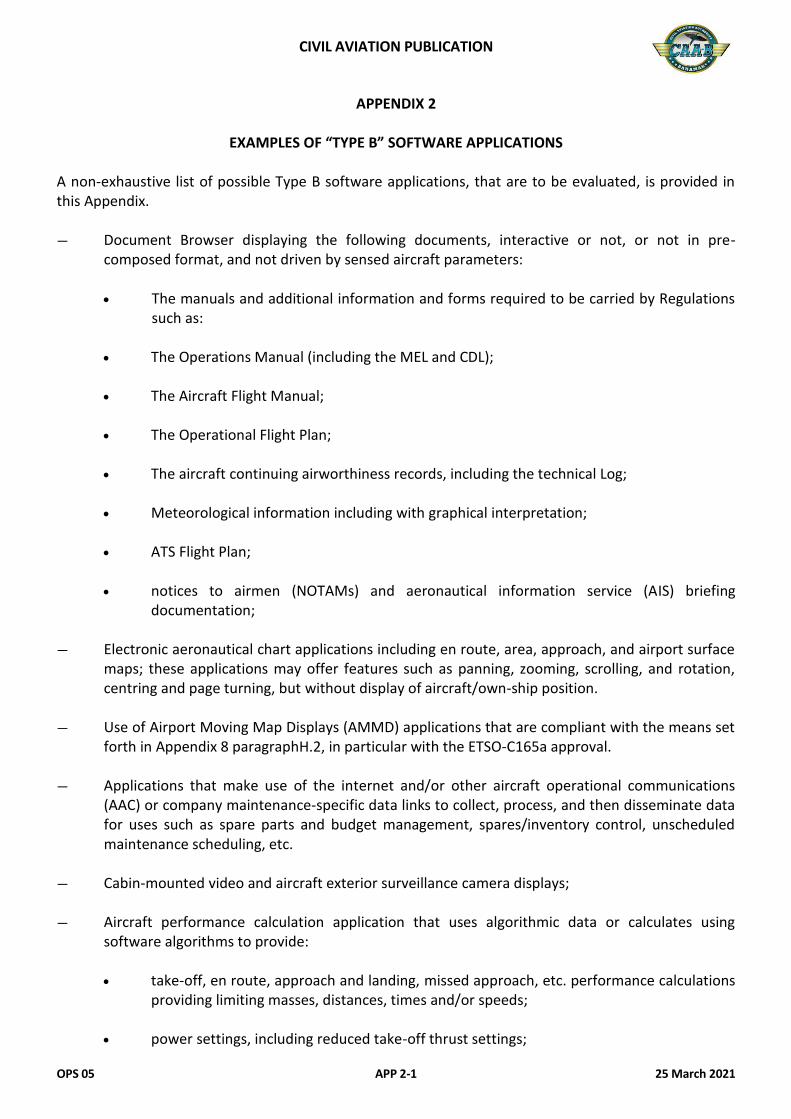
CIVIL AVIATION PUBLICATION
OPS 05 APP 2-1 25 March 2021
APPENDIX 2
EXAMPLES OF “TYPE B” SOFTWARE APPLICATIONS A non-exhaustive list of possible Type B software applications, that are to be evaluated, is provided in this Appendix. — Document Browser displaying the following documents, interactive or not, or not in pre-
composed format, and not driven by sensed aircraft parameters:
The manuals and additional information and forms required to be carried by Regulations such as:
The Operations Manual (including the MEL and CDL); The Aircraft Flight Manual; The Operational Flight Plan; The aircraft continuing airworthiness records, including the technical Log; Meteorological information including with graphical interpretation; ATS Flight Plan; notices to airmen (NOTAMs) and aeronautical information service (AIS) briefing
documentation; — Electronic aeronautical chart applications including en route, area, approach, and airport surface
maps; these applications may offer features such as panning, zooming, scrolling, and rotation, centring and page turning, but without display of aircraft/own-ship position.
— Use of Airport Moving Map Displays (AMMD) applications that are compliant with the means set forth in Appendix 8 paragraphH.2, in particular with the ETSO-C165a approval.
— Applications that make use of the internet and/or other aircraft operational communications (AAC) or company maintenance-specific data links to collect, process, and then disseminate data for uses such as spare parts and budget management, spares/inventory control, unscheduled maintenance scheduling, etc.
— Cabin-mounted video and aircraft exterior surveillance camera displays;
— Aircraft performance calculation application that uses algorithmic data or calculates using software algorithms to provide:
take-off, en route, approach and landing, missed approach, etc. performance calculations
providing limiting masses, distances, times and/or speeds; power settings, including reduced take-off thrust settings;

CIVIL AVIATION PUBLICATION
OPS 05 APP 2-2 25 March 2021
mass and balance calculation application used to establish the mass and centre of gravity of the aircraft and to determine that the load and its distribution is such that the mass and balance limits of the aircraft are not exceeded.
— Airport Moving Map Displays (AMMD) applications not covered by an ETSO-C165a approval;
— Other Type B applications not listed in this Appendix.
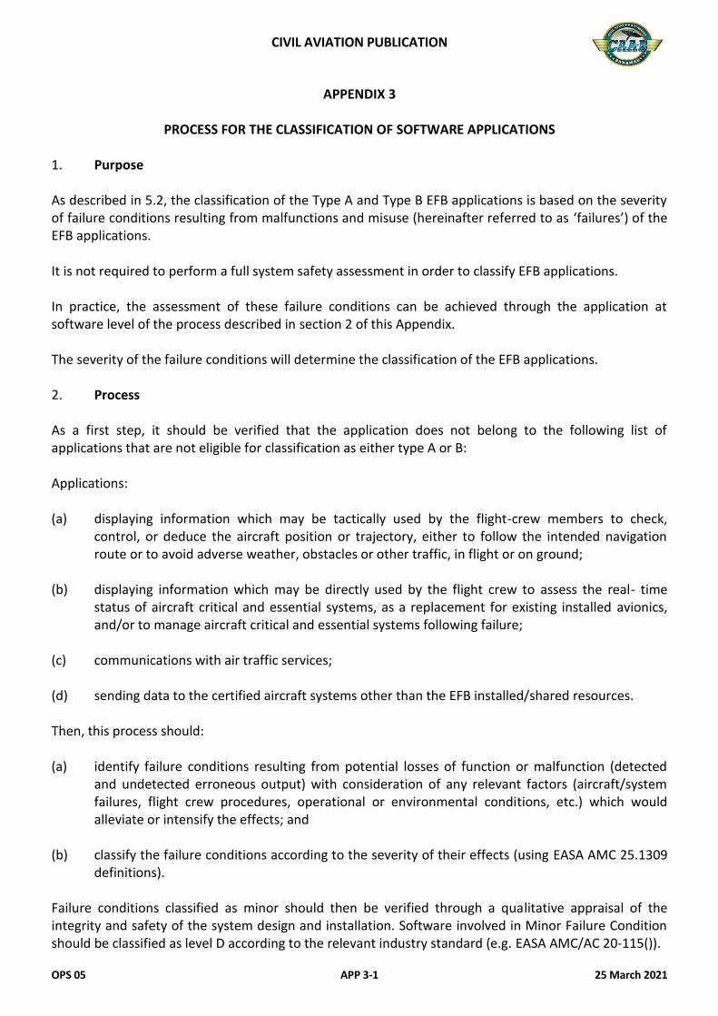
CIVIL AVIATION PUBLICATION
OPS 05 APP 3-1 25 March 2021
APPENDIX 3
PROCESS FOR THE CLASSIFICATION OF SOFTWARE APPLICATIONS 1. Purpose As described in 5.2, the classification of the Type A and Type B EFB applications is based on the severity of failure conditions resulting from malfunctions and misuse (hereinafter referred to as ‘failures’) of the EFB applications. It is not required to perform a full system safety assessment in order to classify EFB applications. In practice, the assessment of these failure conditions can be achieved through the application at software level of the process described in section 2 of this Appendix. The severity of the failure conditions will determine the classification of the EFB applications. 2. Process As a first step, it should be verified that the application does not belong to the following list of applications that are not eligible for classification as either type A or B: Applications: (a) displaying information which may be tactically used by the flight-crew members to check,
control, or deduce the aircraft position or trajectory, either to follow the intended navigation route or to avoid adverse weather, obstacles or other traffic, in flight or on ground;
(b) displaying information which may be directly used by the flight crew to assess the real- time
status of aircraft critical and essential systems, as a replacement for existing installed avionics, and/or to manage aircraft critical and essential systems following failure;
(c) communications with air traffic services; (d) sending data to the certified aircraft systems other than the EFB installed/shared resources. Then, this process should: (a) identify failure conditions resulting from potential losses of function or malfunction (detected
and undetected erroneous output) with consideration of any relevant factors (aircraft/system failures, flight crew procedures, operational or environmental conditions, etc.) which would alleviate or intensify the effects; and
(b) classify the failure conditions according to the severity of their effects (using EASA AMC 25.1309
definitions). Failure conditions classified as minor should then be verified through a qualitative appraisal of the integrity and safety of the system design and installation. Software involved in Minor Failure Condition should be classified as level D according to the relevant industry standard (e.g. EASA AMC/AC 20-115()).

CIVIL AVIATION PUBLICATION
OPS 05 APP 3-2 25 March 2021
Software applications with failure conditions classified above minor are ineligible as EFB Type A or B applications. Notes:
— The severity of the failure conditions linked to displaying a function already existing in the certified type design, or already authorised through an ETSO, and used with same concept of operation, cannot be less than already assessed for this function;
— The data resulting from this process may be reused by the operators in the context of the
EFB risk assessment process described in chapter 7.2.2.
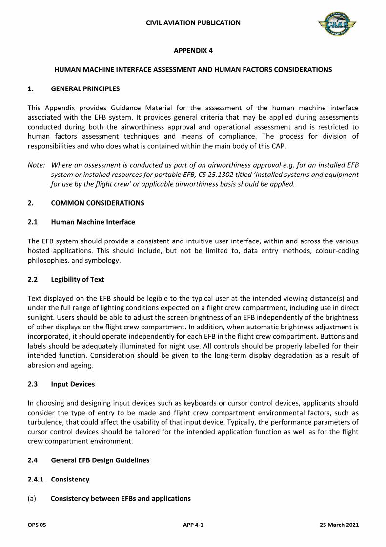
CIVIL AVIATION PUBLICATION
OPS 05 APP 4-1 25 March 2021
APPENDIX 4
HUMAN MACHINE INTERFACE ASSESSMENT AND HUMAN FACTORS CONSIDERATIONS 1. GENERAL PRINCIPLES This Appendix provides Guidance Material for the assessment of the human machine interface associated with the EFB system. It provides general criteria that may be applied during assessments conducted during both the airworthiness approval and operational assessment and is restricted to human factors assessment techniques and means of compliance. The process for division of responsibilities and who does what is contained within the main body of this CAP. Note: Where an assessment is conducted as part of an airworthiness approval e.g. for an installed EFB
system or installed resources for portable EFB, CS 25.1302 titled ‘Installed systems and equipment for use by the flight crew’ or applicable airworthiness basis should be applied.
2. COMMON CONSIDERATIONS 2.1 Human Machine Interface The EFB system should provide a consistent and intuitive user interface, within and across the various hosted applications. This should include, but not be limited to, data entry methods, colour-coding philosophies, and symbology. 2.2 Legibility of Text Text displayed on the EFB should be legible to the typical user at the intended viewing distance(s) and under the full range of lighting conditions expected on a flight crew compartment, including use in direct sunlight. Users should be able to adjust the screen brightness of an EFB independently of the brightness of other displays on the flight crew compartment. In addition, when automatic brightness adjustment is incorporated, it should operate independently for each EFB in the flight crew compartment. Buttons and labels should be adequately illuminated for night use. All controls should be properly labelled for their intended function. Consideration should be given to the long-term display degradation as a result of abrasion and ageing. 2.3 Input Devices In choosing and designing input devices such as keyboards or cursor control devices, applicants should consider the type of entry to be made and flight crew compartment environmental factors, such as turbulence, that could affect the usability of that input device. Typically, the performance parameters of cursor control devices should be tailored for the intended application function as well as for the flight crew compartment environment. 2.4 General EFB Design Guidelines 2.4.1 Consistency
(a) Consistency between EFBs and applications
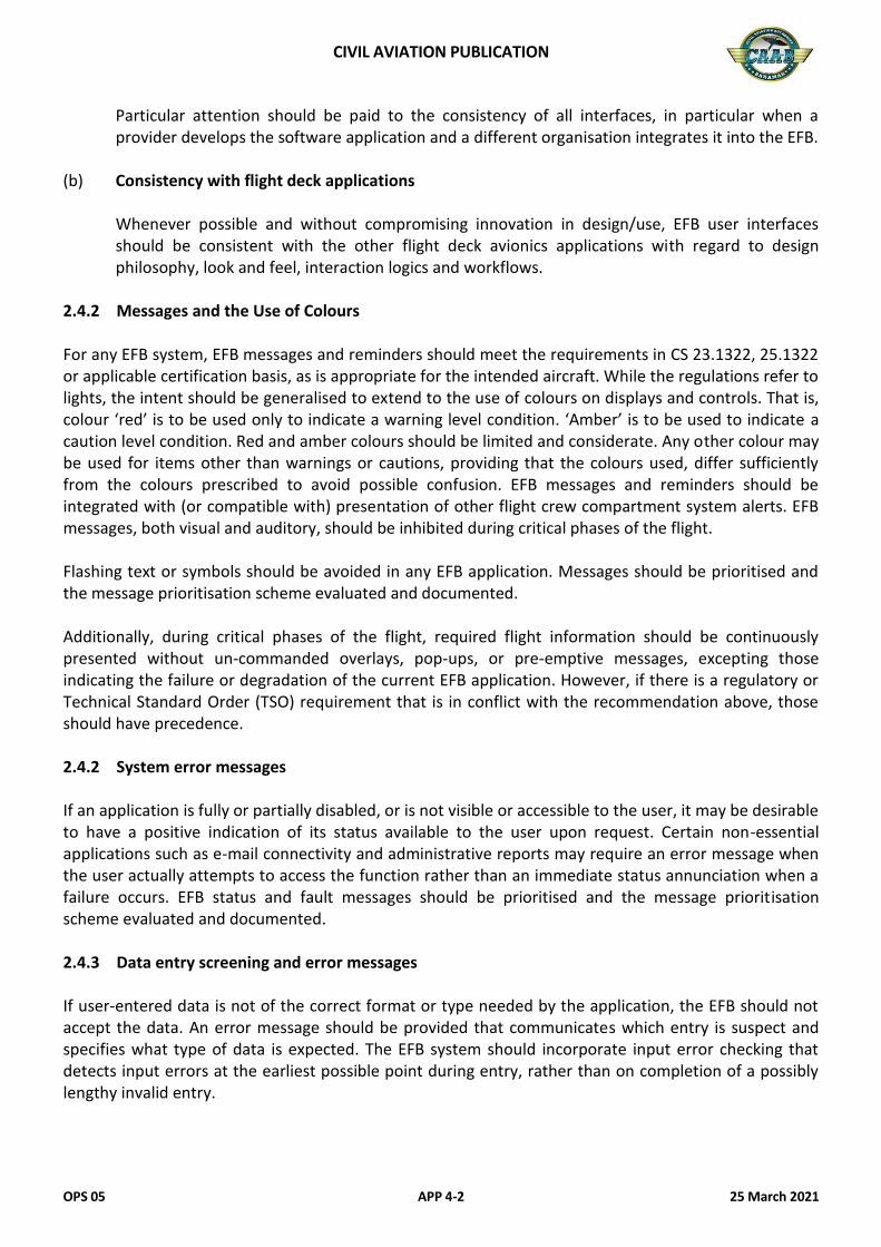
CIVIL AVIATION PUBLICATION
OPS 05 APP 4-2 25 March 2021
Particular attention should be paid to the consistency of all interfaces, in particular when a provider develops the software application and a different organisation integrates it into the EFB.
(b) Consistency with flight deck applications
Whenever possible and without compromising innovation in design/use, EFB user interfaces should be consistent with the other flight deck avionics applications with regard to design philosophy, look and feel, interaction logics and workflows.
2.4.2 Messages and the Use of Colours For any EFB system, EFB messages and reminders should meet the requirements in CS 23.1322, 25.1322 or applicable certification basis, as is appropriate for the intended aircraft. While the regulations refer to lights, the intent should be generalised to extend to the use of colours on displays and controls. That is, colour ‘red’ is to be used only to indicate a warning level condition. ‘Amber’ is to be used to indicate a caution level condition. Red and amber colours should be limited and considerate. Any other colour may be used for items other than warnings or cautions, providing that the colours used, differ sufficiently from the colours prescribed to avoid possible confusion. EFB messages and reminders should be integrated with (or compatible with) presentation of other flight crew compartment system alerts. EFB messages, both visual and auditory, should be inhibited during critical phases of the flight. Flashing text or symbols should be avoided in any EFB application. Messages should be prioritised and the message prioritisation scheme evaluated and documented. Additionally, during critical phases of the flight, required flight information should be continuously presented without un-commanded overlays, pop-ups, or pre-emptive messages, excepting those indicating the failure or degradation of the current EFB application. However, if there is a regulatory or Technical Standard Order (TSO) requirement that is in conflict with the recommendation above, those should have precedence. 2.4.2 System error messages If an application is fully or partially disabled, or is not visible or accessible to the user, it may be desirable to have a positive indication of its status available to the user upon request. Certain non-essential applications such as e-mail connectivity and administrative reports may require an error message when the user actually attempts to access the function rather than an immediate status annunciation when a failure occurs. EFB status and fault messages should be prioritised and the message prioritisation scheme evaluated and documented. 2.4.3 Data entry screening and error messages If user-entered data is not of the correct format or type needed by the application, the EFB should not accept the data. An error message should be provided that communicates which entry is suspect and specifies what type of data is expected. The EFB system should incorporate input error checking that detects input errors at the earliest possible point during entry, rather than on completion of a possibly lengthy invalid entry.
CIVIL AVIATION PUBLICATION
OPS 05 APP 4-3 25 March 2021
2.4.4 Data Entry Screening and Error Messages
If user-entered data is not of the correct format or type needed by the application, the EFB should not accept the data. An error message should be provided that communicates which entry is suspect and specifies what type of data is expected. The EFB system should incorporate input error checking that detects input errors at the earliest possible point during entry, rather than on completion of a possibly lengthy invalid entry. 2.5 Error and Failure Modes
2.5.1 Flight Crew Error The system should be designed to minimise the occurrence and effects of flight crew error and maximise the identification and resolution of errors. For example, terms for specific types of data or the format in which latitude/longitude is entered should be the same across systems. Data entry methods, colour-coding philosophies, and symbology should be as consistent as possible across the various hosted EFB applications. These applications should also be compatible with other flight crew compartment systems. 2.5.2 Identifying Failure Modes The EFB system should be capable of alerting the flight crew of probable EFB system failures. 2.6 Responsiveness of Application The system should provide feedback to the user when user input is accepted. If the system is busy with internal tasks that preclude immediate processing of user input (e.g. calculations, self-test, or data refresh), the EFB should display a ‘system busy’ indicator (e.g. clock icon) to inform the user that the system is occupied and cannot process inputs immediately. The timeliness of system response to user input should be consistent with an application’s intended function. The feedback and system response times should be predictable to avoid flight crew distractions and/or uncertainty. 2.7 Off-Screen Text and Content If the document segment is not visible in its entirety in the available display area, such as during ‘zoom’ or ‘pan’ operations, the existence of off-screen content should be clearly indicated in a consistent way. For some intended functions it may be unacceptable if certain portions of documents are not visible. This should be evaluated based on the application and intended operational function. If there is a cursor, it should be visible on the screen at all times while in use. 2.8 Active Regions
Active regions are regions to which special user commands apply. The active region can be text, a graphic image, a window, frame, or other document object. These regions should be clearly indicated.
CIVIL AVIATION PUBLICATION
OPS 05 APP 4-4 25 March 2021
2.9 Managing Multiple Open Applications and Documents If the electronic document application supports multiple open documents, or the system allows multiple open applications, indication of which application and/or document is active should be continuously provided. The active document is the one that is currently displayed and responds to user actions. Under non-emergency, normal operations, the user should be able to select which of the open applications or documents is currently active. In addition, the user should be able to find which flight crew compartment applications are running and switch to any one of these applications easily. When the user returns to an application that was running in the background, it should appear in the same state as when the user left that application, with the exception of differences stemming from the progress or completion of processing performed in the background. 2.10 Flight Crew Workload The positioning and procedures associated with the use of the EFB should not result in unacceptable flight crew workload. Complex, multi-step data entry tasks should be avoided during take-off, landing, and other critical phases of the flight. An evaluation of the EFB intended functions should include a qualitative assessment of incremental pilot workload, as well as pilot system interfaces and their safety implications. 3. SPECIFIC APPLICATION CONSIDERATIONS 3.1 Approach/Departure and Navigation Chart Display The approach, departure, and navigation charts that are depicted should contain the information necessary, in appropriate form, to conduct the operation to at least a level of safety equivalent to that provided by paper charts. It is desirable that the EFB display size is at least as large as current paper approach charts and that the format be consistent with current paper charts. The HMI assessment is key to identifying acceptable mitigation means, e.g.: (a) to establish procedures to reduce the risk of making errors; (b) to control and mitigate additional workload related to EFB use; (c) to ensure consistency of colour coding and symbology philosophies, between EFB applications
and their compatibility with other flight crew compartment applications; and (d) to consider aspects of Crew Resource Management (CRM) when using an EFB system. D.3.1 Performance applications and mass & balance calculations Input data and output data (results) shall be clearly separated from each other. All the information necessary for a given calculation task should be presented together or easily accessible. All data required for the performance and mass & balance applications should be asked for or displayed, including correct and unambiguous terms (names), units of measurement (e.g. kg or lbs), and when applicable index system and CG-position declaration (e.g. Arm/%MAC). The units should match the ones
CIVIL AVIATION PUBLICATION
OPS 05 APP 4-5 25 March 2021
from the other cockpit sources for the same kind of data. Airspeeds should be provided in a way directly useable in the cockpit unless the unit clearly indicates otherwise (e.g. KCAS). Any difference in the type of airspeed provided by the EFB application and the type provided by the AFM or FCOM performance charts should be mentioned in the pilot guides and training material. If the application allows to compute both dispatch (regulatory, factored) and other results (e.g. in-flight or unfactored), the flight crew should be made aware of the active mode. Inputs The application should allow to clearly distinguish user entries from default values or entries imported from other aircraft systems. Performance applications should offer to the flight crew the ability to check whether a certain obstacle is included in the performance calculation and/or to include revised or new obstacle information in the performance calculation. Outputs All critical performance calculation assumptions (e.g. use of thrust reversers, full or reduced thrust/power rating) should be clearly displayed. The assumptions made about any calculation should be at least as clear to pilots as similar information would be on a tabular chart. All output data should be available in numbers. The application should indicate if a set of entries results in an unachievable operation (for instance a negative stopping margin) with a specific message or colour scheme. This should be done in accordance with D.2.4.2 (Messages and the use of colours). In order to allow a smooth workflow and to prevent data entry errors, the layout of the calculation outputs should be such that it is not inconsistent with the data entry interface of the aircraft applications in which the calculation outputs are used (e.g. Flight Management Systems). Modifications The user should be able to modify performance calculations easily, especially when making last minute changes. Calculation results and any outdated input fields should be deleted: (a) when modifications are entered; (b) when the EFB is shut down or the performance application is closed; and (c) when the EFB or the performance application have been in a standby or ‘background’ mode long
enough, i.e. such that it is likely that when it is used again the inputs or outputs are outdated.

CIVIL AVIATION PUBLICATION
OPS 05 APP 4-6 25 March 2021
This Page Intentionally Left Blank
CIVIL AVIATION PUBLICATION
OPS 05 APP 5-1 25 March 2021
APPENDIX 5
FLIGHT CREW TRAINING The purpose of this Appendix 9s to describe considerations for training and checking when Standard Operating Procedures (SOP) are dependent on the use of an EFB system. 1. EFB TRAINING AND CHECKING 1.1 Assumptions regarding flight crew previous experience Training for the use of the EFB should be for the purpose of operating the EFB itself and the applications hosted on it, and should not be intended to provide basic competence in areas such as aircraft performance, etc. Initial EFB training, therefore, should assume basic competence in the functions addressed by the software applications installed. Training should be adapted to the crew experience and knowledge. 1.2 Programmes crediting previous EFB experience Training programmes for the EFB may take credit for previous EFB experience. For example, previous experience of an aircraft performance application hosted on a portable EFB and using similar software may be credited toward training on an installed EFB with a performance application. 1.3 Initial EFB training Training required for the grant of an aircraft type rating may not recognise variants within the type nor the installation of particular equipment. Any training for the grant of a type qualification need not, therefore, recognise the installation or use of an EFB unless it is installed equipment across all variants of the type. However, where training for the issue of the type rating is combined with the operator’s conversion course required by ORO.FC.220, the training syllabus should recognise the installation of the EFB where the operator’s SOPs are dependent on its use. Initial EFB Training may consist of both ground-based and in-flight training depending on the nature and complexity of the EFB system. An operator or approved training organisation (ATO) may use many methods for ground-based EFB training including written hand-outs or FCOM material, classroom instruction, pictures, videotape, ground training devices, computer-based instruction, FSTD, and static aircraft training. Ground-based training for a sophisticated EFB lends itself particularly to CBT-based instruction. In-flight EFB training should be conducted by a suitably qualified person during Line Flying Under Supervision or during Differences, Conversion or Familiarisation Training. 1.3.1 Areas of emphasis during initial EFB training (a) The use of the EFB hardware and the need for proper adjustment of lighting, etc. when the
system is used in-flight; (b) The intended use of each software application together with limitations and prohibitions on their
use;
CIVIL AVIATION PUBLICATION
OPS 05 APP 5-2 25 March 2021
(c) If an aircraft performance application is installed, proper cross-checking of data input and output;
(d) If a terminal chart application is installed, proper verification of the applicability of the
information being used; (e) If a moving map display is installed, the need to avoid fixation on the map display; and (f) Failure of component(s) of the EFB. 1.3.2 Typical initial EFB training The following might be a typical training syllabus, if not contrasting with the operational suitability data provided by the aircraft manufacturer. Ground-based training (a) System architecture overview; (b) Display Unit features and use; (c) Limitations of the system; (d) Restrictions on the use of the system;
(1) Phases of the flight; (2) Alternate procedures (e.g. MEL).
(e) Applications as installed; (f) Use of each application; (g) Restrictions on the use of each application;
(1) Phases of the flight; (2) Alternate procedures (e.g. MEL).
(h) Data input; (i) Cross-checking data input and output; and (j) Use of data output.
1.3.3 Flight training (a) Practical use of the Display Unit;
CIVIL AVIATION PUBLICATION
OPS 05 APP 5-3 25 March 2021
(b) Display Unit Controls; (c) Data input devices; (d) Selection of applications; (e) Practical use of applications; (f) CRM and human factor considerations; (g) Situational awareness; (h) Avoidance of fixation; (i) Cross-checking data input and output; and (j) Practical integration of EFB procedures into SOPs.
1.4 Initial EFB checking 1.4.1 Initial ground EFB checking The check conducted following the ground-based element of Initial EFB Training may be accomplished by questionnaire (oral or written) or as an automated component of EFB computer-based training depending on the nature of the training conducted. 1.4.2 Skill test & proficiency check Proficiency in EFB use is not shown in the required items in CAR LIC for the Skill Test for the issue of a type rating following type conversion training or for the Proficiency Check for the renewal or revalidation of a type rating. Where the operator’s SOPs are dependent on the use of the EFB on the particular type or variant, proficiency in the use of the EFB should be assessed in the appropriate areas. Operator proficiency check
CAR OPS 1/3 requires that flight crew demonstrate their competence in carrying out normal procedures during the Operator Proficiency Check (OPC). Therefore, where an operator’s SOPs are dependent on the use of an EFB, proficiency in its use should be assessed during the OPC. Where the OPC is performed on an FSTD not equipped with the operator’s EFB, proficiency should be assessed by another acceptable means. 1.4.3 Line check CAR OPS 1/3 requires that flight crew demonstrate their competence in carrying out normal procedures during the line check. Therefore, where an operator’s SOPs are dependent on the use of an EFB, proficiency in its use should be assessed during line check.
CIVIL AVIATION PUBLICATION
OPS 05 APP 5-4 25 March 2021
1.4.4 Areas of emphasis during EFB checking (a) Proficiency in the use of each EFB application installed; (b) Proper selection and use of EFB displays; (c) Where an aircraft performance application is installed, proper cross-checking of data input and
output; (d) Where a terminal chart application is installed, proper check of the validity of the information
and the use of the chart clip function; (e) Where a moving map display is installed, maintenance of a proper outside visual scan without
prolonged fixation on EFB operation, especially during the taxiing operations; and (f) Actions following the failure of component(s) of the EFB, including hot EFB battery. 2. DIFFERENCES OR FAMILIARISATION TRAINING When the introduction of the use of an EFB requires Differences or Familiarisation Training to be carried out under CAR OPS 1/3, the elements of Initial EFB Training should be used, as described above. 3. RECURRENT EFB TRAINING AND CHECKING 3.1 Recurrent EFB training Recurrent training is normally not required for the use of an EFB, provided the functions are used regularly in line operations. Operators should be encouraged, however, to include normal EFB operations as a component of the annual ground and refresher training. In the case of mixed fleet flying, or where the EFB is not installed across the fleet, additional recurrent training should be applied. Initial training programme developed under 1.3 is considered to be sufficient. 3.2 Recurrent EFB Checking Recurrent EFB checking should consist of those elements of the licence proficiency check, the operator proficiency check and the line check applicable to the use of an EFB as described in paragraphs 1.4.1, 1.4.2, and 1.4.3 of this Appendix. Areas of emphasis are as described in paragraph 1.4.4. 3.3 Suitability of training devices Where the operator’s SOPs are dependent on the use of an EFB, it is recommended that the EFB is present during the operator’s training and checking. Where present, the EFB should be configured and operable in all respects as per the relevant aircraft. This should apply to: (a) the operator’s conversion course; (b) Differences or familiarisation training; and
CIVIL AVIATION PUBLICATION
OPS 05 APP 5-5 25 March 2021
(c) Recurrent training and checking.
Where the EFB system is based on a portable device used without any installed resources, it is recommended that the device is present and operable and used during all phases of the flight during which it would be used under the operator’s SOPs. For all other types of EFB system, it is recommended that the device is installed and operable in the training device (FFS) and used during all phases of the flight during which it would be used under the operator’s SOPs. However, an operator may define an alternative means of compliance when the operator’s EFB system is neither installed nor operable in the training device. Note: It is not necessary for the EFB to be available for that training and checking which is not related
to the operator and the operator’s SOPs.
Where the EFB is installed equipment in the basic aircraft type or variant, the installation and use of the EFB in the training device is required for the training and checking for the issue of the type rating and for the checking for the renewal or revalidation of the type rating.

CIVIL AVIATION PUBLICATION
OPS 05 APP 5-6 25 March 2021
This Page Intentionally Left Blank
CIVIL AVIATION PUBLICATION
OPS 05 APP 6-1 25 March 2021
APPENDIX 6
SOFTWARE APPLICATION DOCUMENTATION The operator should retain the following documentation: (a) Functional description document (for the initial assessment and any subsequent functional
change); (b) Release notes (for both initial and all subsequent software releases) or equivalent; (c) Version description document (for both initial and all subsequent releases); (d) First article inspection report (refers to quality controlled release of the EFB Software
Application); (e) Ground viewer (to enable user validation of the software releases and data base releases and
updates);
(1) Viewers should use the same software components as the airborne application; and (2) Viewers should enable user validity checking of airborne data bases before installation on
an aircraft. 1. ADDITIONAL REQUIREMENTS FOR PERFORMANCE APPLICATIONS
(for take-off, landing and mass & balance calculations) 1.1 General The performance and mass & balance applications should be based on existing published data found in the AFM or performance manual, and deliver results that allow the crew to operate in compliance with CAR OPS 1/3. The applications may use algorithms or data spread sheets to determine results. They may have the ability to interpolate within but should not extrapolate beyond the information contained in the published data for the aircraft. If the programme is designed to be used by operators under different regulation frameworks and allows one to choose between CAA-B and other NAA regulations, this choice should be protected so that it is accessible only to the administrator. To protect against intentional and unintentional modifications, the database files related to performance and mass & balance (performance database, airport database, etc.) integrity should be checked by the programme before performing calculation. This check can be run once at the start-up of the application. Each software version should be identified by a unique version number. Only specific modules of the performance or M&B software application are approved, for a specific software revision and on a specific host (e.g. computer model).The performance and mass & balance applications should keep a trace of each computation performed (inputs and outputs) and the airline should have procedures in place to retain this information.
CIVIL AVIATION PUBLICATION
OPS 05 APP 6-2 25 March 2021
1.2 Testing The demonstration of the compliance of a performance or mass & balance application should include evidence of the software testing activities performed with the software version candidate for operational use. The testing can be performed either by the operator or a third party, as long as the testing process is documented and the responsibilities identified. The testing activities should include HMI testing, reliability testing, and accuracy testing.
HMI testing should demonstrate that the application is not error-prone and that calculation errors can be detected by the crew with the proposed procedures. The testing should demonstrate that the applicable HMI guidelines are followed and that the HMI is implemented as specified by the application developer and this CAP. Refer to Appendix 4, para 3.2 for further information.
Reliability testing should show that the application in its operating environment (OS and hardware included) is stable and deterministic, i.e. identical answers are generated each time the process is entered with identical parameters. 1.2.1 Accuracy testing Accuracy testing should demonstrate that the aircraft performance or mass & balance computations provided by the application are correct in comparison with data derived from the AFM or other appropriate sources, under a representative cross section of conditions (e.g. for performance applications: runway state and slope, different wind conditions and pressure altitudes, various aircraft configuration including failures with a performance impact, etc.). The demonstration should include a sufficient number of comparison results from representative calculations throughout the entire operating envelope of the aircraft, considering corner points, routine and break points. Operators are expected to justify that they covered a sufficient number of testing points with respect to the design of their software application and databases. Any difference compared to the reference data that is judged significant should be examined and explained. When differences come from a reduced conservatism or reduced margins that were purposely built into the approved data, this approach should be clearly mentioned and motivated. Compliance to the certification and operational rules need to be demonstrated in any case. The testing method should be described. The testing may be automated when all the required data is available in appropriate electronic format, but in addition to a thorough monitoring of the correct functioning and design of the testing tools and procedures, it is strongly suggested to perform additional manual verification. It could be based on a few scenarios for each chart or table of the reference data, including both operationally representative scenarios and ‘corner- case’ scenarios. The testing of a software revision should, in addition, include non-regression testing and testing of any fix or change.
CIVIL AVIATION PUBLICATION
OPS 05 APP 6-3 25 March 2021
Furthermore, an operator should conduct testing related to its customisation of the applications and to any element proper to its operation that was not covered at an earlier stage (e.g. airport database verification). 1.3 Procedures In addition to the provisions of chapter 7.6, specific care is needed regarding the crew procedures concerning performance or mass and balance applications: (a) Crew procedures should ensure that calculations are conducted independently by each crew
member before data outputs are accepted for use. (b) Crew procedures should ensure that a formal cross-check is made before data outputs are
accepted for use. Such cross-checks should utilise the independent calculations described above, together with the output of the same data from other sources on the aircraft.
(c) Crew procedures should ensure that a gross-error check is conducted before data outputs are
accepted for use. Such a gross-error check may use either a ‘rule of thumb’ or the output of the same data from other sources on the aircraft.
(d) Crew procedures should ensure that, in the event of loss of functionality by an EFB through
either the loss of a single application, or the failure of the device hosting the application, an equivalent level of safety can be maintained. Consistency with the EFB Risk Assessment assumptions should be confirmed.
1.4 Training In addition to the provisions of chapter 7.13, the training should emphasise the importance of executing all performance calculations in accordance with the SOPs to assure fully independent calculations. Furthermore, due to the optimisation at different levels brought by performance applications, the crew may be confronted with new procedures and different aircraft behaviour (e.g. use of multiple flaps settings for take-off). The training should be designed and provided accordingly. Where an application allows computing both dispatch (regulatory calculations, factored calculations) and other results, the training should highlight the specificities of those results. Depending of the representativeness of the calculation, the crew should be trained on the operational margin that might be required. The training should also address the identification and the review of default values, if any, and assumptions about the aircraft status or environmental conditions made by the application. 1.5 Additional considerations for mass & balance applications The basic data used for the mass & balance calculation should be modifiable by the EFB Administrator himself/herself or by the software application provider on behalf of the EFB Administrator.
In addition to the figures, a graph should visualise the mass and its associated CG-position.

CIVIL AVIATION PUBLICATION
OPS 05 APP 6-4 25 March 2021
This Page Intentionally Left Blank
CIVIL AVIATION PUBLICATION
OPS 05 APP 7-1 25 March 2021
APPENDIX 7
EFB POLICY & PROCEDURES MANUAL These are the typical contents of an EFB policy and procedures manual that can be part of the Operation Manual. The proposed outline is very extensive. It may be adapted to the specific EFBs system and to the size and complexity of the operations in which the operator is involved. 1. Revision history 2. List of effective pages or paragraphs 3. Table of contents 4. Introduction
Glossary of terms and acronyms EFB general philosophy, environment and dataflow EFB system architecture Limitations of the EFB system Hardware description Operating system description Detailed presentation of the EFB applications EFB application customisation Data management:
- Data administration - Organisation & workflows - Data loading - Data revision mechanisms - Approval workflow - Data publishing & dispatch - Customisation - How to manage the airline specific documents - Airport data management - Aircraft fleet definition
Data authoring - Navigation and customisation
5. Hardware and operating system control and configuration
Purpose and scope Description of the following processes:
- Hardware configuration and part No control - Operating system configuration and control - Accessibility control - Hardware maintenance - Operating system updating
Responsibilities and accountabilities Records and filing Documentary references
6. Software application control and configuration
Purpose and scope Description of the following processes:
CIVIL AVIATION PUBLICATION
OPS 05 APP 7-2 25 March 2021
- Part No control - Software configuration management - Application updating process
Responsibilities and accountabilities Records and filing Documentary references
7. Flight crew
Training Operating procedures (normal, abnormal, and emergency)
8. Maintenance considerations 9. EFB security policy
Security solutions and procedures
CIVIL AVIATION PUBLICATION
OPS 05 APP 8-1 25 March 2021
APPENDIX 8
AIRPORT MOVING MAP DISPLAY (AMMD) APPLICATION WITH OWN-SHIP POSITION 1. GENERAL CONSIDERATIONS 1.1 Preamble This Appendix guides the applicant in how to demonstrate the safe operational use for AMMD applications as a Type B software application to be hosted in EFBs. It is recognised that an AMMD can aid pilot positional awareness on the airport manoeuvring area and the CAA-B proposes to allow AMMDs to be Type B application under the conditions established in this Appendix 8. 1.2 Assumptions of intended use of an AMMD An AMMD application is not used as the primary means of taxiing navigation and is only used in conjunction with other materials and procedures identified within the Operating Concept – see paragraph H.3. Note: When an AMMD is in use, the primary means of taxiing navigation remains the use of normal procedures and direct visual observation out of the cockpit window. Thus, as recognised in ETSO-C165a, an AMMD application with display of own-ship position is considered as having a minor safety effect for malfunctions causing the incorrect depiction of aircraft position (own-ship), and the failure condition for the loss of function is classified as ‘no safety effect.’ 2. APPROVAL OF AMMD IN EFBS 2.1 Minimum requirements The AMMD software and database that is compliant with the European Technical Standard Order ETSO-C165a, or an equivalent standard, with following AMMD system features implemented, is considered acceptable: (a) The system provides means to display the revision number of the software installed. (b) The system is capable of accepting updated airport mapping information and provides means to
display the validity period of the database to the flight crew. The flight crew should be able to easily ascertain the validity of the on-board map database. The application should provide an indication when the AMMD database is no longer valid. Refer to section 2.2.5 of RTCA DO-257A as per section 3.1.1 of ETSO-C165a.
(c) The Total System Accuracy of the end-to-end system is specified and characterised, and does not
exceed 50 meters (95 %).
CIVIL AVIATION PUBLICATION
OPS 05 APP 8-2 25 March 2021
Note: An airworthiness-approved sensor using the Global Positioning System (GPS) in combination with a RTCA DO-272 medium accuracy compliant database is considered one acceptable means to satisfy this requirement.
(d) The system automatically removes the own-ship position when the aircraft is in flight (using e.g.
weight on wheels discrete or speed monitoring) and when the estimated position uncertainty exceeds the maximum value. Refer to sections 3 and 4 in Appendix 1 of ETSO-C165a.
(e) It is recommended that the AMMD detects, annunciates to the flight crew, and fully removes
depiction of own-ship data, in case of any loss or degradation of AMMD functions due to failures such as memory corruption, frozen system, latency, etc. Refer to section 1 in Appendix 1 of ETSO-C165a.
(f) Data Quality Requirements (DQRs) for the AMMD data base. 2.2 Data provided by the AMMD software application developer The AMMD software application developer should provide the appropriate data to each integrator in an EFB: (a) The executable object code in an acceptable transferring medium; (b) Installation instructions or equivalent as per ETSO-C165a section 2.2. addressing:
(1) identification of each target EFB system computing platform (including hardware platform and operating system version) with which this AMMD software application and database was demonstrated to be compatible;
(2) installation procedures and limitations to address the AMMD installation requirements
for each applicable platform such as target computer resource requirements (e.g. memory resources) to ensure the AMMD will work properly when integrated and installed;
(3) interface description data including the requirements for external sensors providing data
inputs; and (4) verification means required to verify proper integration of the AMMD in the target
platform environment, including identification of additional activities that the integrator of an EFB must perform to ensure the AMMD meets its intended function, such as testing in the aircraft.
(c) Any AMMD limitations, and known installation, operational, functional, or performance issues on
the AMMD. 2.3 AMMD software installation in the EFB The operator should review the documents and the data provided by the AMMD developer, and ensure that the installation requirements of the AMMD software in the specific EFB platform and aircraft are addressed. The following activities are required:
CIVIL AVIATION PUBLICATION
OPS 05 APP 8-3 25 March 2021
(a) Ensure that the software and database are compatible with the EFB system computing platform on which they are intended to function, including the analysis of compatibility of the AMMD with other EFB Type A and B software applications residing in the same platform. Follow the programme installation instructions provided by the software supplier, as applicable to the compatible EFB computer.
(b) Check that the objectives for installation, assumptions, limitations and requirements for the
AMMD, as part of the data provided by the AMMD software application developer (see H.2.2), are satisfied.
(c) Perform any verification activities proposed by the AMMD software application developer, as
well as identify and perform additional integration activities to be completed. (d) Ensure the compatibility and the compliance with requirements for data provided by other
installed systems, such as a GNSS sensor and latency assumptions. 3. OPERATING CONCEPT The operating concept should include, as minimum: (a) pilot operation, including confirmation of effectivity; (b) handling of updates; (c) quality assurance function; (d) handling of NOTAMS; and (e) the provision of current maps and charts to cover the intended operation of the aeroplane. Changes to operational or procedural characteristics of the aircraft (e.g. Flight crew procedures) are documented in the Operations Manual or user’s guide as appropriate. In particular, the following text is required: Note: This EFB airport moving map display (AMMD) with own-ship position symbol is designed to assist
flight crews in orienting themselves on the airport surface to improve pilot positional awareness during taxi operations. The AMMD function is not to be used as the basis for ground manoeuvring. This application is limited to ground operations only.
4. TRAINING REQUIREMENTS The operator may use flight crew procedures to mitigate some hazards. This will include limitations on the use of the AMMD function. As the AMMD could be a compelling display and the procedural restrictions are a key component of the mitigation, training should be provided in support of an AMMD’s implementation. Any mitigation to hazards that are mitigated by flight crew procedures should be included in flight crew training. Details of AMMD training should be included in the operator’s overall EFB training (refer to Appendix 5).

CIVIL AVIATION PUBLICATION
OPS 05 APP 8-4 25 March 2021
This Page Intentionally Left Blank
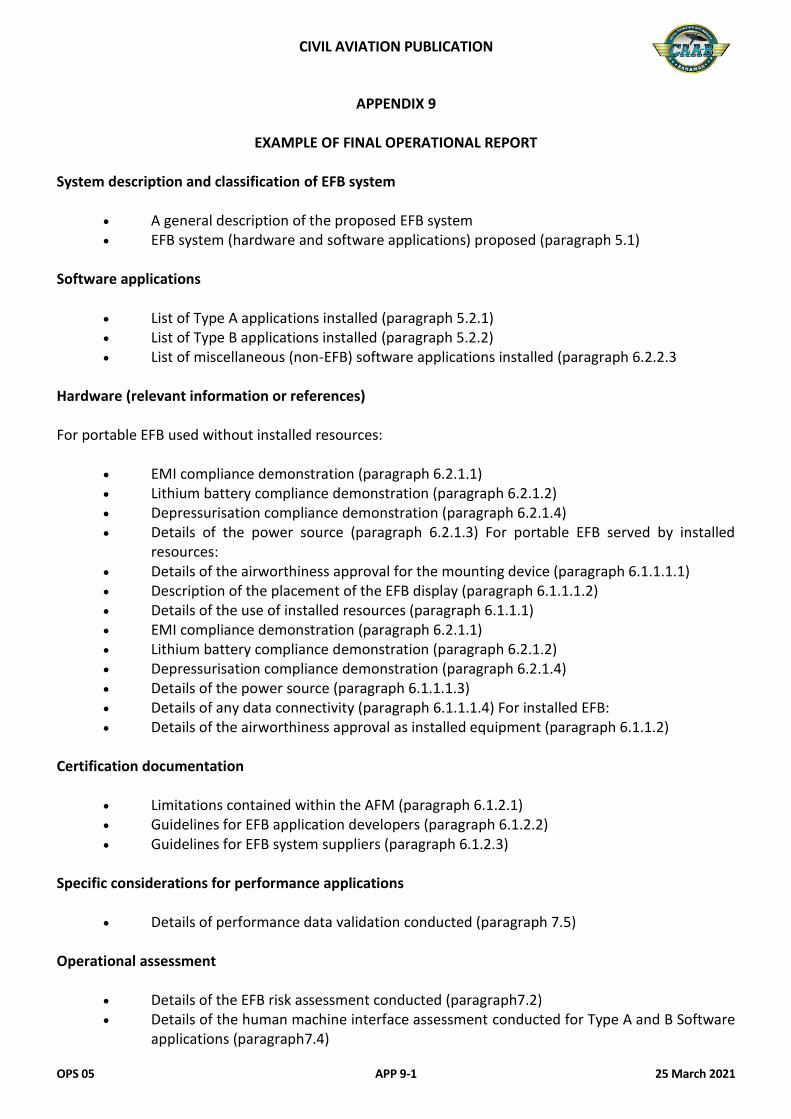
CIVIL AVIATION PUBLICATION
OPS 05 APP 9-1 25 March 2021
APPENDIX 9
EXAMPLE OF FINAL OPERATIONAL REPORT System description and classification of EFB system
A general description of the proposed EFB system EFB system (hardware and software applications) proposed (paragraph 5.1)
Software applications
List of Type A applications installed (paragraph 5.2.1) List of Type B applications installed (paragraph 5.2.2) List of miscellaneous (non-EFB) software applications installed (paragraph 6.2.2.3
Hardware (relevant information or references) For portable EFB used without installed resources:
EMI compliance demonstration (paragraph 6.2.1.1) Lithium battery compliance demonstration (paragraph 6.2.1.2) Depressurisation compliance demonstration (paragraph 6.2.1.4) Details of the power source (paragraph 6.2.1.3) For portable EFB served by installed
resources: Details of the airworthiness approval for the mounting device (paragraph 6.1.1.1.1) Description of the placement of the EFB display (paragraph 6.1.1.1.2) Details of the use of installed resources (paragraph 6.1.1.1) EMI compliance demonstration (paragraph 6.2.1.1) Lithium battery compliance demonstration (paragraph 6.2.1.2) Depressurisation compliance demonstration (paragraph 6.2.1.4) Details of the power source (paragraph 6.1.1.1.3) Details of any data connectivity (paragraph 6.1.1.1.4) For installed EFB: Details of the airworthiness approval as installed equipment (paragraph 6.1.1.2)
Certification documentation
Limitations contained within the AFM (paragraph 6.1.2.1) Guidelines for EFB application developers (paragraph 6.1.2.2) Guidelines for EFB system suppliers (paragraph 6.1.2.3)
Specific considerations for performance applications
Details of performance data validation conducted (paragraph 7.5) Operational assessment
Details of the EFB risk assessment conducted (paragraph7.2) Details of the human machine interface assessment conducted for Type A and B Software
applications (paragraph7.4)
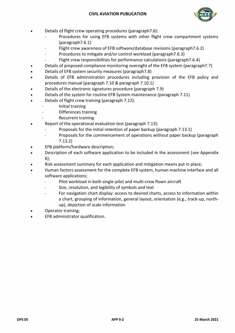
CIVIL AVIATION PUBLICATION
OPS 05 APP 9-2 25 March 2021
Details of flight crew operating procedures (paragraph7.6): - Procedures for using EFB systems with other flight crew compartment systems
(paragraph7.6.1) - Flight crew awareness of EFB software/database revisions (paragraph7.6.2) - Procedures to mitigate and/or control workload (paragraph7.6.3) - Flight crew responsibilities for performance calculations (paragraph7.6.4)
Details of proposed compliance monitoring oversight of the EFB system (paragraph7.7) Details of EFB system security measures (paragraph7.8) Details of EFB administration procedures including provision of the EFB policy and
procedures manual (paragraph 7.10 & paragraph 7.10.1) Details of the electronic signatures procedure (paragraph 7.9) Details of the system for routine EFB System maintenance (paragraph 7.11) Details of flight crew training (paragraph 7.12):
- Initial training - Differences training - Recurrent training
Report of the operational evaluation test (paragraph 7.13): - Proposals for the initial retention of paper backup (paragraph 7.13.1) - Proposals for the commencement of operations without paper backup (paragraph
7.13.2) EFB platform/hardware description; Description of each software application to be included in the assessment (see Appendix
6); Risk assessment summary for each application and mitigation means put in place; Human factors assessment for the complete EFB system, human machine interface and all
software applications; - Pilot workload in both single-pilot and multi-crew flown aircraft - Size, resolution, and legibility of symbols and text - For navigation chart display: access to desired charts, access to information within
a chart, grouping of information, general layout, orientation (e.g., track-up, north-up), depiction of scale information
Operator training; EFB administrator qualification.

CIVIL AVIATION PUBLICATION
OPS 05 APP 10-1 25 March 2021
APPENDIX 10
POWER SUPPLY CONSIDERATIONS FOR PORTABLE EFBS If an EFB is permanently attached to the essential power network, it could affect the essential generation system (emergency generator and/or battery, bus bars, distribution system) to which it is connected. Certification specifications require that an alternate high integrity electrical power supply system, independent of the normal electrical power system, be provided to power those services necessary for continued safe flight and landing, in case of loss of the normal system. Adding other unnecessary services/loads will affect the integrity of this alternate power system. Portable and installed EFBs are considered non-essential equipment and, therefore, not considered necessary for continued safe flight and landing. It is, hence, not recommended to connect the EFB to an essential power bus.

CIVIL AVIATION PUBLICATION
OPS 05 APP 10-2 25 March 2021
This Page Intentionally Left Blank
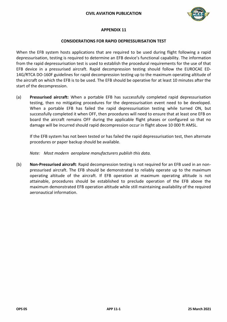
CIVIL AVIATION PUBLICATION
OPS 05 APP 11-1 25 March 2021
APPENDIX 11
CONSIDERATIONS FOR RAPID DEPRESSURISATION TEST When the EFB system hosts applications that are required to be used during flight following a rapid depressurisation, testing is required to determine an EFB device’s functional capability. The information from the rapid depressurisation test is used to establish the procedural requirements for the use of that EFB device in a pressurised aircraft. Rapid decompression testing should follow the EUROCAE ED-14G/RTCA DO-160F guidelines for rapid decompression testing up to the maximum operating altitude of the aircraft on which the EFB is to be used. The EFB should be operative for at least 10 minutes after the start of the decompression. (a) Pressurised aircraft: When a portable EFB has successfully completed rapid depressurisation
testing, then no mitigating procedures for the depressurisation event need to be developed. When a portable EFB has failed the rapid depressurisation testing while turned ON, but successfully completed it when OFF, then procedures will need to ensure that at least one EFB on board the aircraft remains OFF during the applicable flight phases or configured so that no damage will be incurred should rapid decompression occur in flight above 10 000 ft AMSL.
If the EFB system has not been tested or has failed the rapid depressurisation test, then alternate
procedures or paper backup should be available. Note: Most modern aeroplane manufacturers publish this data. (b) Non-Pressurised aircraft: Rapid decompression testing is not required for an EFB used in an non-
pressurised aircraft. The EFB should be demonstrated to reliably operate up to the maximum operating altitude of the aircraft. If EFB operation at maximum operating altitude is not attainable, procedures should be established to preclude operation of the EFB above the maximum demonstrated EFB operation altitude while still maintaining availability of the required aeronautical information.

CIVIL AVIATION PUBLICATION
OPS 05 APP 11-2 25 March 2021
This Page Intentionally Left Blank
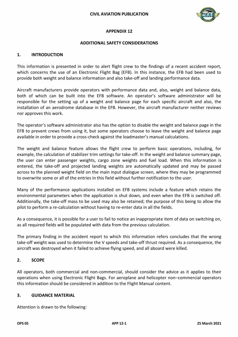
CIVIL AVIATION PUBLICATION
OPS 05 APP 12-1 25 March 2021
APPENDIX 12
ADDITIONAL SAFETY CONSIDERATIONS 1. INTRODUCTION This information is presented in order to alert flight crew to the findings of a recent accident report, which concerns the use of an Electronic Flight Bag (EFB). In this instance, the EFB had been used to provide both weight and balance information and also take-off and landing performance data. Aircraft manufacturers provide operators with performance data and, also, weight and balance data, both of which can be built into the EFB software. An operator’s software administrator will be responsible for the setting up of a weight and balance page for each specific aircraft and also, the installation of an aerodrome database in the EFB. However, the aircraft manufacturer neither reviews nor approves this work. The operator’s software administrator also has the option to disable the weight and balance page in the EFB to prevent crews from using it, but some operators choose to leave the weight and balance page available in order to provide a cross-check against the loadmaster’s manual calculations. The weight and balance feature allows the flight crew to perform basic operations, including, for example, the calculation of stabilizer trim settings for take-off. In the weight and balance summary page, the user can enter passenger weights, cargo zone weights and fuel load. When this information is entered, the take-off and projected landing weights are automatically updated and may be passed across to the planned weight field on the main input dialogue screen, where they may be programmed to overwrite some or all of the entries in this field without further notification to the user. Many of the performance applications installed on EFB systems include a feature which retains the environmental parameters when the application is shut down, and even when the EFB is switched off. Additionally, the take-off mass to be used may also be retained; the purpose of this being to allow the pilot to perform a re-calculation without having to re-enter data in all the fields. As a consequence, it is possible for a user to fail to notice an inappropriate item of data on switching on, as all required fields will be populated with data from the previous calculation. The primary finding in the accident report to which this information refers concludes that the wrong take-off weight was used to determine the V speeds and take-off thrust required. As a consequence, the aircraft was destroyed when it failed to achieve flying speed, and all aboard were killed. 2. SCOPE All operators, both commercial and non-commercial, should consider the advice as it applies to their operations when using Electronic Flight Bags. For aeroplane and helicopter non–commercial operators this information should be considered in addition to the Flight Manual content. 3. GUIDANCE MATERIAL Attention is drawn to the following:
CIVIL AVIATION PUBLICATION
OPS 05 APP 12-2 25 March 2021
An operational approval allows an operator to use an EFB to replace traditional paper sources of information if, “an acceptable level of accessibility, usability and reliability can be assured”. Implicit in this rule is the need to provide adequate levels of cross-checking and a methodology that ensures the identification of gross errors when using an electronic system, which is comparable to the industry best practice established for manual systems. Crew procedures for the use of traditional paper performance charts often include practices that recognize basic human factors principles associated with the influence of decisions and acceptance of the validity of information and these should be carried over to the use of electronic calculation and the presentation of this kind of data. The use of a single EFB on the flight deck poses the same risks with regard to the acceptance of data output as do those posed by having only one pilot on a multi-crew aeroplane determining performance data from a paper chart. Standard Operating Procedures for the use of an EFB should include procedures that utilize independent calculation by each crew member, provide for effective cross-checking and facilitate the trapping of gross errors. 4. RECOMMENDATION 4.1 Operators are recommended to modify EFB software so as to prevent: (a) Other applications from inputting data into any field on the performance application feature
when this is used to derive operational performance for a critical phase of flight, and (b) Any field in the performance application which is used to derive operational performance for a
critical phase of flight from remaining populated after the EFB is shut down. Where these actions cannot be achieved by means of software modification, operators should ensure that crew procedures include the requirement, before any calculation is conducted, to enter or re-enter data manually in any fields in the performance application that are used to derive operational performance for a critical phase of flight, 4.2 Operators are recommended to establish and provide training on EFB operating procedures. 4.2.1 Crew procedures should ensure that calculations are conducted independently by each crew
member before data outputs are accepted for use.
Crew procedures should ensure that a formal cross-check is made before data outputs are accepted for use. Such cross-checks should utilize the independent calculations described in 4.2.1 above, together with the output of the same data from other sources on the aircraft.
Crew procedures should ensure that a gross-error check is conducted before data outputs are accepted for use. Such a gross-error check may use either a “rule of thumb” or the output of the same data from other sources on the aircraft. Crew procedures should ensure that, in the event of loss of functionality by an EFB through either the loss of a single application, or the failure of the device hosting the application, an equivalent level of security of data output can be maintained by the use of alternative procedures.