Embed Size (px)
Citation preview
Operations Manual May 2011
Revisions
No. Revision Date Software Version Comment
1.0 November 2nd
, 2009 1.0.0 First edition
1.1 February 9th, 2010 1.0.3 Update
1.2 February 16th, 2010 1.0.3 Slight layout and text changes due to
proofreading
1.3 May 9th, 2010 1.1.0 New software version
1.4 November 12th, 2010 1.2.0 New software version
1.5 December 11th, 2010 1.2.1 Update
1.6 March 11th, 2011 1.3.0 New software version
1.7 March 31st, 2011 1.3.1 Update
1.8 May 21st, 2011 1.3.1 SP2 New "SaveAs" Dialog
Copyright © 2011, by AivlaSoft GmbH, All rights reserved.
No part of this manual may be reproduced or transmitted or uploaded to any server location or distributed
in any form without the written permission of AivlaSoft GmbH.
For more information contact:
AivlaSoft GmbH 8627 Grüningen Switzerland www.aivlasoft.com [email protected]
Other Copyrights and Trademarks
Microsoft, Flight Simulator X, FSX, Windows 7, Windows Vista, Windows XP and Windows are either
registered trademarks or trademarks of Microsoft Corporation in the United States and/or other countries.
GOOGLE and Google Earth are trademarks of Google, Inc.
“Real Environment Xtreme” is a trademark of Real Environment Simulations, Inc.
“IVAO” is a trademark of International Virtual Aviation Organisation
Other products and services mentioned in this manual are the property of their respective owners. All
rights reserved.
No affiliation with AivlaSoft GmbH or its products and services should be inferred or implied by usage
herein.
Table of contents
Section 1 - Introduction ......................................................................................................................................... 1
OVERVIEW ................................................................................................................................................................... 2
FEATURES .................................................................................................................................................................... 2
PROGRAM UPDATES, SUPPORT ........................................................................................................................................ 3
CREDITS, LICENSES ......................................................................................................................................................... 3
Section 2 - DataProvider ........................................................................................................................................ 1
MENU BAR ................................................................................................................................................................... 2
UPDATING FSX DATA, INSTALLING OR REMOVING SCENERY .................................................................................................... 2
MESSAGES ON THE DATAPROVIDER WINDOW ..................................................................................................................... 3 Messages that need attention from the pilot....................................................................................................... 3 The "Runways.txt" file .......................................................................................................................................... 4 Different scenarios ............................................................................................................................................... 5 Solution................................................................................................................................................................. 6
Section 3 - DisplayUnit .......................................................................................................................................... 1
AREAS OF THE DISPLAYUNIT ............................................................................................................................................ 2
MENU BAR ................................................................................................................................................................... 3 Status and Time .................................................................................................................................................... 3 Route dependent modules.................................................................................................................................... 4 Chart dependent options ...................................................................................................................................... 4 Sub menus ............................................................................................................................................................ 5
CHARTS ORGANIZATION .................................................................................................................................................. 7 Route oriented ...................................................................................................................................................... 7 Airport oriented .................................................................................................................................................... 7
REMOTE CONTROLLED FROM FSX MENU ............................................................................................................................ 8
Section 4 - Airport Database ................................................................................................................................. 1
OVERVIEW ................................................................................................................................................................... 2
SELECTING AIRPORT DATA ................................................................................................................................................ 3 Selection criteria ................................................................................................................................................... 3 Arranging the results ............................................................................................................................................ 3 Using the touch screen keyboard ......................................................................................................................... 4 Custom filters ....................................................................................................................................................... 5 Combining filters .................................................................................................................................................. 7 Edit a custom filter ............................................................................................................................................... 8 Runway assignment warning ............................................................................................................................... 9
Section 5 - Route Setup ......................................................................................................................................... 1
OVERVIEW ................................................................................................................................................................... 2 Valid route ............................................................................................................................................................ 2
SELECT A ROUTE ............................................................................................................................................................ 3 Load an EFB route ................................................................................................................................................ 3 Load a saved route ............................................................................................................................................... 3 Load a route from VATroute ................................................................................................................................. 5 Load a route from RouteFinder ............................................................................................................................ 7 Create a route from an ATS route description ...................................................................................................... 8 Create a simple route ......................................................................................................................................... 12 Define alternate airports .................................................................................................................................... 12 Clear route .......................................................................................................................................................... 12 Preview route ..................................................................................................................................................... 13 Save route ........................................................................................................................................................... 14 Activate route ..................................................................................................................................................... 16 Modify route ....................................................................................................................................................... 16 Insert/Remove Enroute waypoints ..................................................................................................................... 18 Creating a Garmin GPS flight plan ...................................................................................................................... 20
Section 6 - Progress ............................................................................................................................................... 1
OVERVIEW ................................................................................................................................................................... 2 Charts organization .............................................................................................................................................. 2 Automatic chart switching ................................................................................................................................... 3 Manual chart switching ........................................................................................................................................ 4 Checklists organization ......................................................................................................................................... 6
Section 7 - Charts .................................................................................................................................................. 1
OVERVIEW ................................................................................................................................................................... 2 Chart Header ........................................................................................................................................................ 2 Communications ................................................................................................................................................... 2 Chart details and Legend ...................................................................................................................................... 4 Toolbar ............................................................................................................................................................... 13 Chart objects ...................................................................................................................................................... 14 Chart dependent menus ..................................................................................................................................... 14
GROUND CHART .......................................................................................................................................................... 15 Submenu ............................................................................................................................................................. 15 Chart Objects ...................................................................................................................................................... 18
DEPARTURE CHART ...................................................................................................................................................... 20 Submenu ............................................................................................................................................................. 20 Chart Objects ...................................................................................................................................................... 24
ENROUTE CHART .......................................................................................................................................................... 25 Submenu ............................................................................................................................................................. 25
ARRIVAL CHART ........................................................................................................................................................... 28 Submenu ............................................................................................................................................................. 28
APPROACH CHART ........................................................................................................................................................ 29 Submenu ............................................................................................................................................................. 29 Plan view ............................................................................................................................................................ 31 Vertical Profile view ............................................................................................................................................ 32
Briefing Strip ....................................................................................................................................................... 33 Descent values .................................................................................................................................................... 33 Panel Options ..................................................................................................................................................... 35
"ACTIVATED" PROCEDURE VS. "SELECTED" PROCEDURE ....................................................................................................... 36
Section 8 - Flight Information System .................................................................................................................... 1
OVERVIEW ................................................................................................................................................................... 2
ACCURACY ................................................................................................................................................................... 2
DEFINITIONS ................................................................................................................................................................. 2
FLIGHT INFORMATION PANEL ........................................................................................................................................... 4 Information shown along the flight profile .......................................................................................................... 5 About “descent altitude constraints” ................................................................................................................. 12
RATE OF DESCENT (ROD, R/D) ..................................................................................................................................... 14
SPECIAL INDICATIONS.................................................................................................................................................... 15
Section 9 - METAR ................................................................................................................................................. 1
OVERVIEW ................................................................................................................................................................... 2
METAR DATA SOURCES ................................................................................................................................................. 3
MEANING OF METAR DATA ............................................................................................................................................ 3 Surface Conditions ................................................................................................................................................ 3 Derived data ......................................................................................................................................................... 4 Flight Conditions ................................................................................................................................................... 4 Upper Level Conditions ......................................................................................................................................... 5 METAR Remarks, Other Info, and limitations on weather data ........................................................................... 6
Section 10 - Flying "online" ................................................................................................................................... 1
PREREQUISITES .............................................................................................................................................................. 2
FLYING ........................................................................................................................................................................ 2 Start/Stop data download .................................................................................................................................... 2
FEATURES .................................................................................................................................................................... 4 Frequency Ribbon ................................................................................................................................................. 4 Setting the frequency ........................................................................................................................................... 5 Digital ATIS ........................................................................................................................................................... 5 Chart Details ......................................................................................................................................................... 6 Online Traffic Preview .......................................................................................................................................... 7
FLYING ALONG THE BOUNDARY BETWEEN TWO FIRS/ARTCCS ............................................................................................... 8
STARTUP SEQUENCE ....................................................................................................................................................... 9
SCREENSHOTS ............................................................................................................................................................... 9
Section 11 - Flightlog ............................................................................................................................................. 1
OVERVIEW ................................................................................................................................................................... 2
FLIGHT PHASE RECOGNITION ............................................................................................................................................ 2
FLIGHT LOG REPRESENTATION........................................................................................................................................... 2 Timestamps .......................................................................................................................................................... 3 Max Flight Time and Fuel Flow ............................................................................................................................. 3 Passing waypoints ................................................................................................................................................ 4 Saving the flight log .............................................................................................................................................. 4
Section 12 - Checklists ........................................................................................................................................... 1
OVERVIEW ................................................................................................................................................................... 2
NORMAL CHECKLIST ....................................................................................................................................................... 3
ABNORMAL CHECKLIST .................................................................................................................................................... 4 Conditional and non-conditional items ................................................................................................................ 5
CHECKLISTS-EDITOR ....................................................................................................................................................... 6 Creating or changing a checklist .......................................................................................................................... 7
Section 13 - Library ................................................................................................................................................ 1
OVERVIEW ................................................................................................................................................................... 2
ADDING DOCUMENTS ..................................................................................................................................................... 2 Flexibility of the library ......................................................................................................................................... 3

Page 1 of 3
Copyright 2011 by AivlaSoft GmbH - www.aivlasoft.com
Section 1 - Introduction
Section 1 - Introduction
Page 2 of 3
Copyright 2011 by AivlaSoft GmbH - www.aivlasoft.com
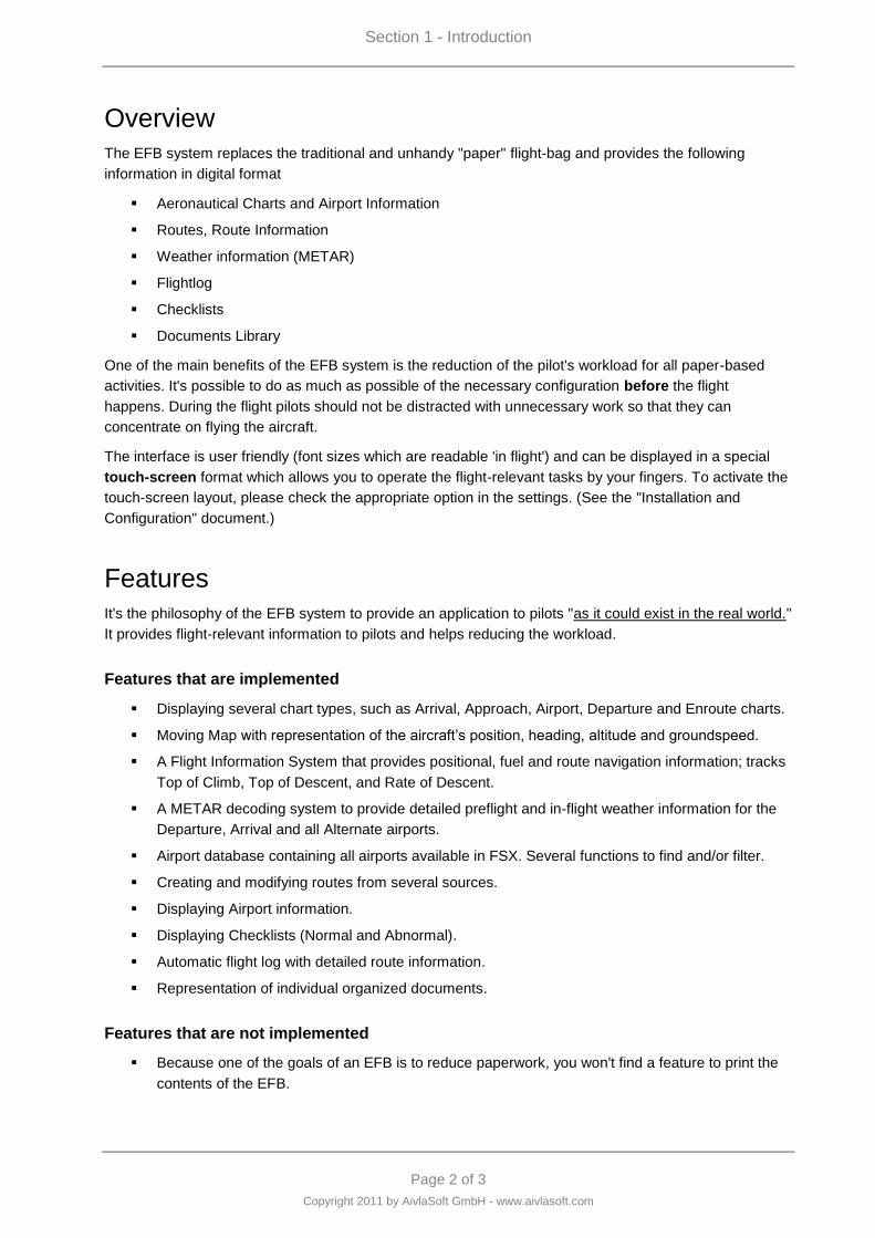
Overview
The EFB system replaces the traditional and unhandy "paper" flight-bag and provides the following
information in digital format
Aeronautical Charts and Airport Information
Routes, Route Information
Weather information (METAR)
Flightlog
Checklists
Documents Library
One of the main benefits of the EFB system is the reduction of the pilot's workload for all paper-based
activities. It's possible to do as much as possible of the necessary configuration before the flight
happens. During the flight pilots should not be distracted with unnecessary work so that they can
concentrate on flying the aircraft.
The interface is user friendly (font sizes which are readable 'in flight') and can be displayed in a special
touch-screen format which allows you to operate the flight-relevant tasks by your fingers. To activate the
touch-screen layout, please check the appropriate option in the settings. (See the "Installation and
Configuration" document.)
Features
It's the philosophy of the EFB system to provide an application to pilots "as it could exist in the real world."
It provides flight-relevant information to pilots and helps reducing the workload.
Features that are implemented
Displaying several chart types, such as Arrival, Approach, Airport, Departure and Enroute charts.
Moving Map with representation of the aircraft‟s position, heading, altitude and groundspeed.
A Flight Information System that provides positional, fuel and route navigation information; tracks
Top of Climb, Top of Descent, and Rate of Descent.
A METAR decoding system to provide detailed preflight and in-flight weather information for the
Departure, Arrival and all Alternate airports.
Airport database containing all airports available in FSX. Several functions to find and/or filter.
Creating and modifying routes from several sources.
Displaying Airport information.
Displaying Checklists (Normal and Abnormal).
Automatic flight log with detailed route information.
Representation of individual organized documents.
Features that are not implemented
Because one of the goals of an EFB is to reduce paperwork, you won't find a feature to print the
contents of the EFB.
Section 1 - Introduction
Page 3 of 3
Copyright 2011 by AivlaSoft GmbH - www.aivlasoft.com
Program Updates, Support
For downloading the latest version, please go to: http://www.aivlasoft.com ( > Downloads)
Issues may be reported either at the support forum: http://www.aivlasoft.com/support or by e-mail
Credits, Licenses
Gabriel N. Schenker Many thanks to Gabriel Schenker who was a patient teacher to me in spherical
geometry and mathematics as well. From him I could also learn a lot of things concerning agile
development, test driven development, and so on. He is a member with the famous "Los Techies Group."
Please visit his blog at: http://www.lostechies.com/blogs/gabrielschenker/default.aspx
Travis Guy Many thanks to Travis Guy for proofreading the English manuals. With his aviation
knowledge he always is a reliable source of good and feasible ideas on how to improve EFB. Also many
thanks for programming the METAR decoder software and many of the flightplan export/import modules.
Also a big "thank you" for all the help you provide to our users due to your fast and qualified support.
Beta Testers In alphabetical order: "Andydigital", Wycliffe Barrett, Dave Birch, "CoolP", Bruno
Emmenegger, Peter Koller, Bernhard Lienemann, Patrick Maeyens, Torsten Reuter, Günter Steiner,
Oski Wagner, Walter Zach.
Navigraph The default AIRAC 1101 dataset is provided by Navigraph. Many thanks to Navigraph for
this generous gesture. Current revisions may be purchased from http://www.navigraph.com.
log4net http://logging.apache.org/log4net/license.html
HtmlAgilityPack http://htmlagilitypack.codeplex.com/license
GSHHS Global Self-consistent Hierarchical High-resolution Shorelines. Distributed under the GNU
Public License: http://www.soest.hawaii.edu/wessel/gshhs/gshhs.html
Castle Project The project is released under the terms of Apache Software Foundation
Ed Williams http://williams.best.vwh.net/ On this very interesting website concerning aviation stuff I
found the source code for the calculation of the magnetic variation. The source code has been released
under the GNU GPL.
IGRF International Geomagnetic Reference Field http://www.ngdc.noaa.gov/IAGA/vmod/
NOAA Sunrise and sunset calculations: http://www.srrb.noaa.gov/highlights/sunrise/gen.html


Page 1 of 8
Copyright 2011 by AivlaSoft GmbH - www.aivlasoft.com
Section 2 - DataProvider
Section 2 - DataProvider
Page 2 of 8
Copyright 2011 by AivlaSoft GmbH - www.aivlasoft.com
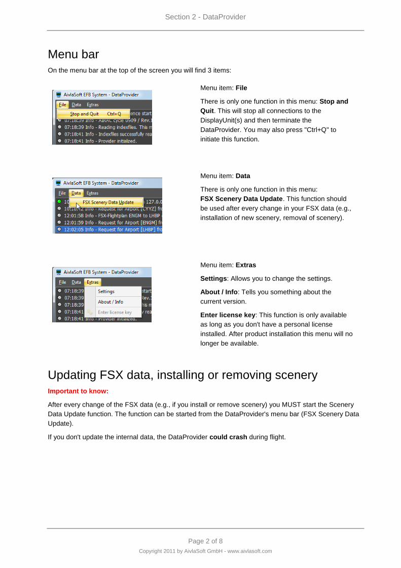
Menu bar
On the menu bar at the top of the screen you will find 3 items:
Menu item: File
There is only one function in this menu: Stop and
Quit. This will stop all connections to the
DisplayUnit(s) and then terminate the
DataProvider. You may also press "Ctrl+Q" to
initiate this function.
Menu item: Data
There is only one function in this menu:
FSX Scenery Data Update. This function should
be used after every change in your FSX data (e.g.,
installation of new scenery, removal of scenery).
Menu item: Extras
Settings: Allows you to change the settings.
About / Info: Tells you something about the
current version.
Enter license key: This function is only available
as long as you don't have a personal license
installed. After product installation this menu will no
longer be available.
Updating FSX data, installing or removing scenery
Important to know:
After every change of the FSX data (e.g., if you install or remove scenery) you MUST start the Scenery
Data Update function. The function can be started from the DataProvider's menu bar (FSX Scenery Data
Update).
If you don't update the internal data, the DataProvider could crash during flight.
Section 2 - DataProvider
Page 3 of 8
Copyright 2011 by AivlaSoft GmbH - www.aivlasoft.com
Messages on the DataProvider window
Every message that you may see on the DataProvider window is also be written into the logfile of the
DataProvider. The messages are subdivided into 4 categories:
information (grey)
warning (yellow)
error (red)
success (green)
Most of these messages you don't have to care about. They all are written into the DataProvider‟s logfile
and are only interesting to the developer or the supporter. If you need support from AivlaSoft you should
have these logfiles ready to be sent to AivlaSoft ([email protected]).
Please see the installation section for more information about "Files and Folders."
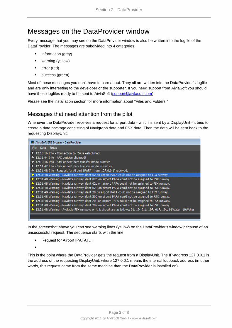
Messages that need attention from the pilot
Whenever the DataProvider receives a request for airport data - which is sent by a DisplayUnit - it tries to
create a data package consisting of Navigraph data and FSX data. Then the data will be sent back to the
requesting DisplayUnit.
In the screenshot above you can see warning lines (yellow) on the DataProvider's window because of an
unsuccessful request. The sequence starts with the line
Request for Airport [PAFA] …
This is the point where the DataProvider gets the request from a DisplayUnit. The IP-address 127.0.0.1 is
the address of the requesting DisplayUnit, where 127.0.0.1 means the internal loopback address (in other
words, this request came from the same machine than the DataProvider is installed on).
Section 2 - DataProvider
Page 4 of 8
Copyright 2011 by AivlaSoft GmbH - www.aivlasoft.com
After getting a data request, the DataProvider tries to create the data package consisting of Navigraph
data and FSX data. These warnings derive from the conflict between Navigraph and FSX data. Usually
Navigraph data represents a more current situation as opposed to the FSX data which generally
represents the time where the data had been integrated into FSX (dating back to 2005). Therefore it
might happen that there is a difference between these data sources. In the above shown screenshot you
may see several warnings which should help to resolve the conflict.
… ident 02 on airport PAFA could not …
… ident 02C …
… …
Available FSX runways … are 01, 19, 01L …
As you may see, the Navigraph runway identifiers are slightly different from the FSX identifiers. In such a
situation the DataProvider is telling you that it is not able to assign the identifiers because it cannot know
why and how the runway identifiers have been changed. At this point your interaction is needed.
The "Runways.txt" file
Depending on your installation the 'Runways.txt'- file can be found within the following folder:
VISTA/W7 C:\Users\[User Name]\Documents\AivlaSoft\EFB\UserData
WinXP C:\Documents and Settings\[User Name]\My Documents\
AivlaSoft\EFB\UserData
This file contains information about the correct assigning of FSX-runway identifiers and Navigraph
runway identifiers.
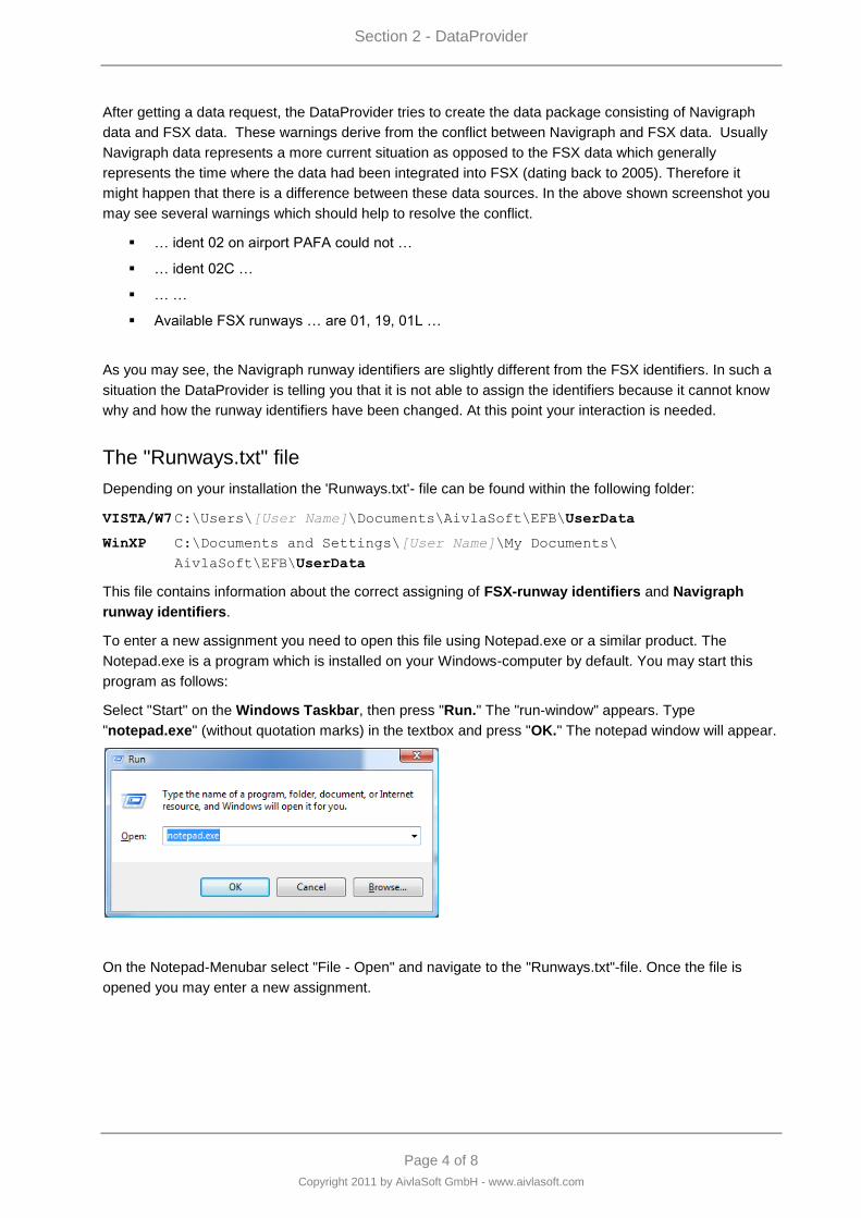
To enter a new assignment you need to open this file using Notepad.exe or a similar product. The
Notepad.exe is a program which is installed on your Windows-computer by default. You may start this
program as follows:
Select "Start" on the Windows Taskbar, then press "Run." The "run-window" appears. Type
"notepad.exe" (without quotation marks) in the textbox and press "OK." The notepad window will appear.
On the Notepad-Menubar select "File - Open" and navigate to the "Runways.txt"-file. Once the file is
opened you may enter a new assignment.
Section 2 - DataProvider
Page 5 of 8
Copyright 2011 by AivlaSoft GmbH - www.aivlasoft.com
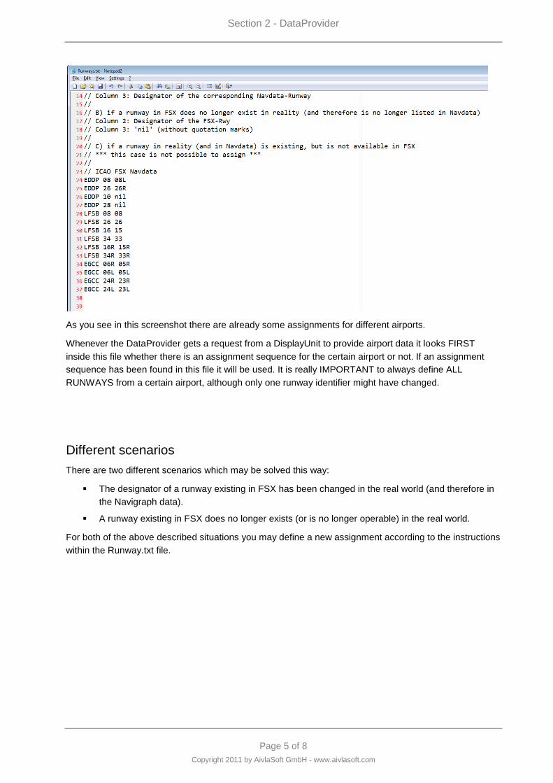
As you see in this screenshot there are already some assignments for different airports.
Whenever the DataProvider gets a request from a DisplayUnit to provide airport data it looks FIRST
inside this file whether there is an assignment sequence for the certain airport or not. If an assignment
sequence has been found in this file it will be used. It is really IMPORTANT to always define ALL
RUNWAYS from a certain airport, although only one runway identifier might have changed.
Different scenarios
There are two different scenarios which may be solved this way:
The designator of a runway existing in FSX has been changed in the real world (and therefore in
the Navigraph data).
A runway existing in FSX does no longer exists (or is no longer operable) in the real world.
For both of the above described situations you may define a new assignment according to the instructions
within the Runway.txt file.
Section 2 - DataProvider
Page 6 of 8
Copyright 2011 by AivlaSoft GmbH - www.aivlasoft.com
Solution
Let's define the new assignments for the airport PAFA – Fairbanks International, Alaska - US.
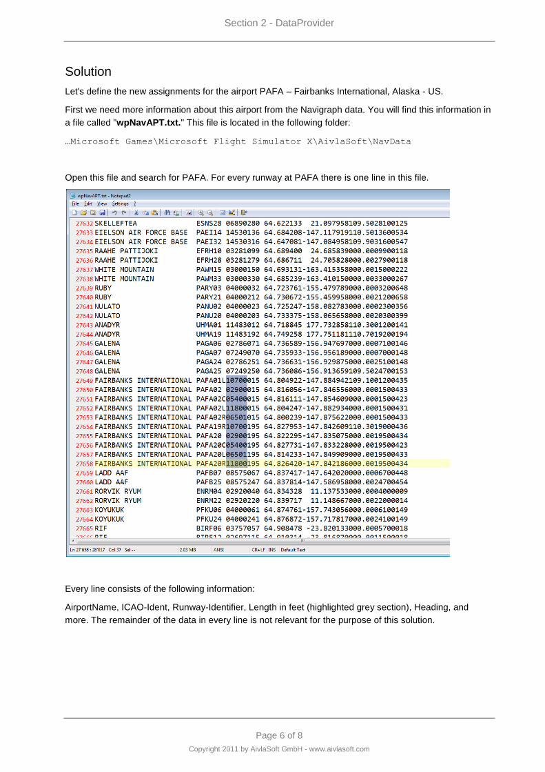
First we need more information about this airport from the Navigraph data. You will find this information in
a file called "wpNavAPT.txt." This file is located in the following folder:
…Microsoft Games\Microsoft Flight Simulator X\AivlaSoft\NavData
Open this file and search for PAFA. For every runway at PAFA there is one line in this file.
Every line consists of the following information:
AirportName, ICAO-Ident, Runway-Identifier, Length in feet (highlighted grey section), Heading, and
more. The remainder of the data in every line is not relevant for the purpose of this solution.
Section 2 - DataProvider
Page 7 of 8
Copyright 2011 by AivlaSoft GmbH - www.aivlasoft.com
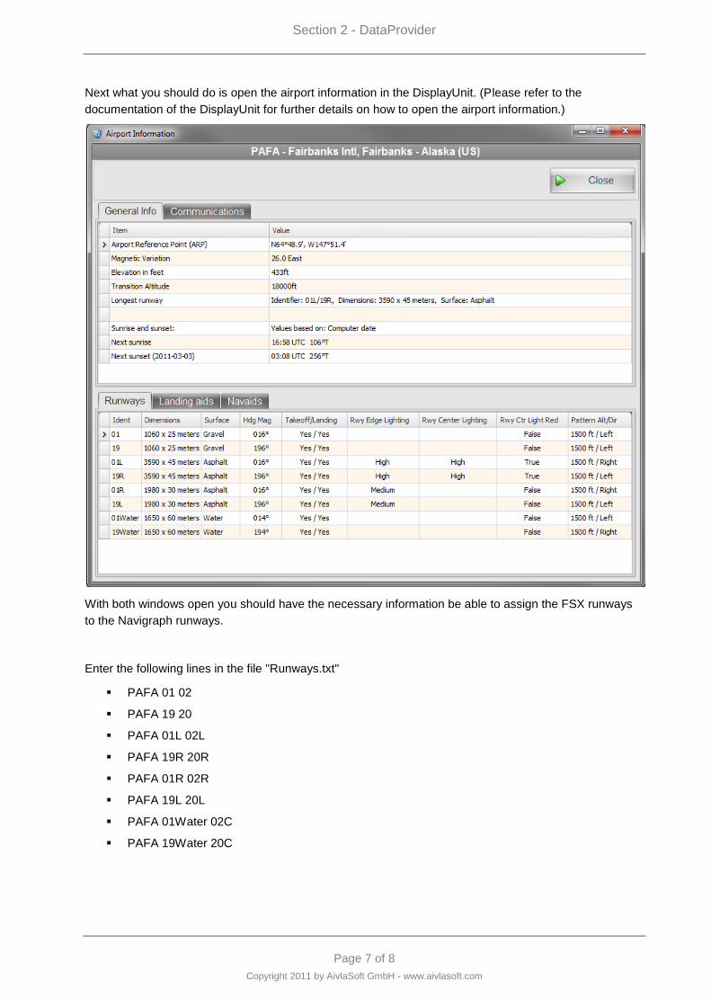
Next what you should do is open the airport information in the DisplayUnit. (Please refer to the
documentation of the DisplayUnit for further details on how to open the airport information.)
With both windows open you should have the necessary information be able to assign the FSX runways
to the Navigraph runways.
Enter the following lines in the file "Runways.txt"
PAFA 01 02
PAFA 19 20
PAFA 01L 02L
PAFA 19R 20R
PAFA 01R 02R
PAFA 19L 20L
PAFA 01Water 02C
PAFA 19Water 20C
Section 2 - DataProvider
Page 8 of 8
Copyright 2011 by AivlaSoft GmbH - www.aivlasoft.com
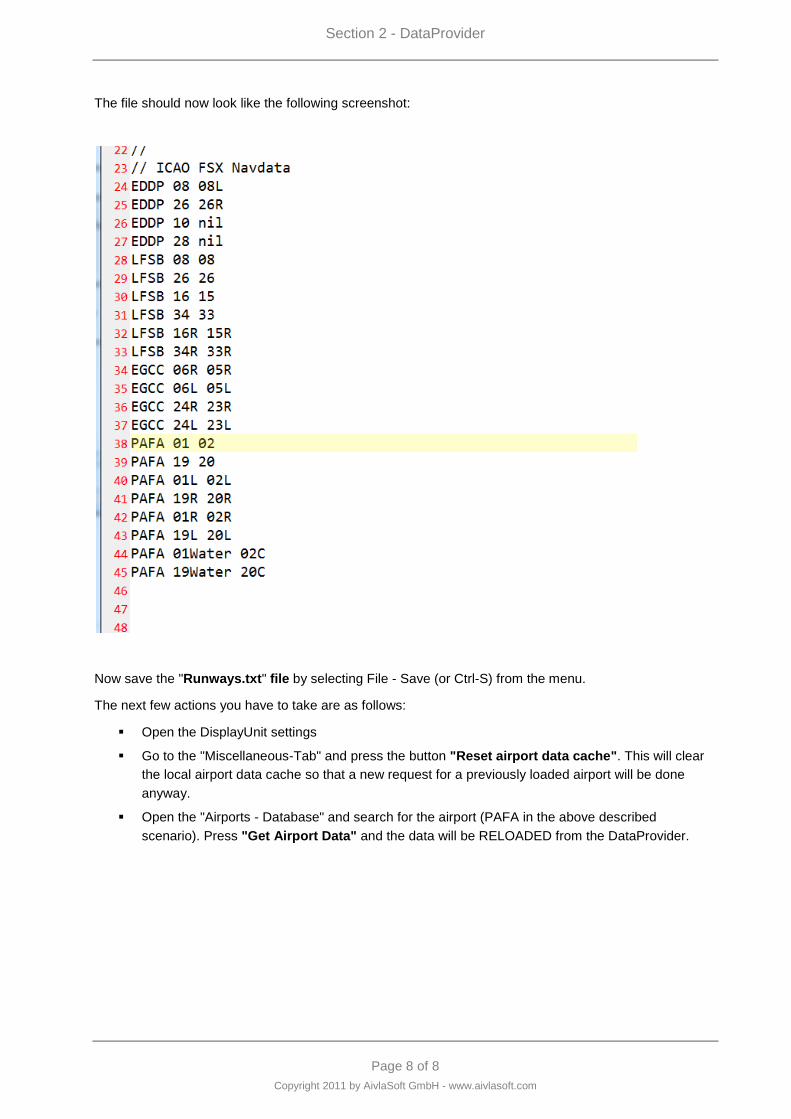
The file should now look like the following screenshot:
Now save the "Runways.txt" file by selecting File - Save (or Ctrl-S) from the menu.
The next few actions you have to take are as follows:
Open the DisplayUnit settings
Go to the "Miscellaneous-Tab" and press the button "Reset airport data cache". This will clear
the local airport data cache so that a new request for a previously loaded airport will be done
anyway.
Open the "Airports - Database" and search for the airport (PAFA in the above described
scenario). Press "Get Airport Data" and the data will be RELOADED from the DataProvider.

Page 1 of 8
Copyright 2011 by AivlaSoft GmbH - www.aivlasoft.com
Section 3 - DisplayUnit
Section 3 - DisplayUnit
Page 2 of 8
Copyright 2011 by AivlaSoft GmbH - www.aivlasoft.com
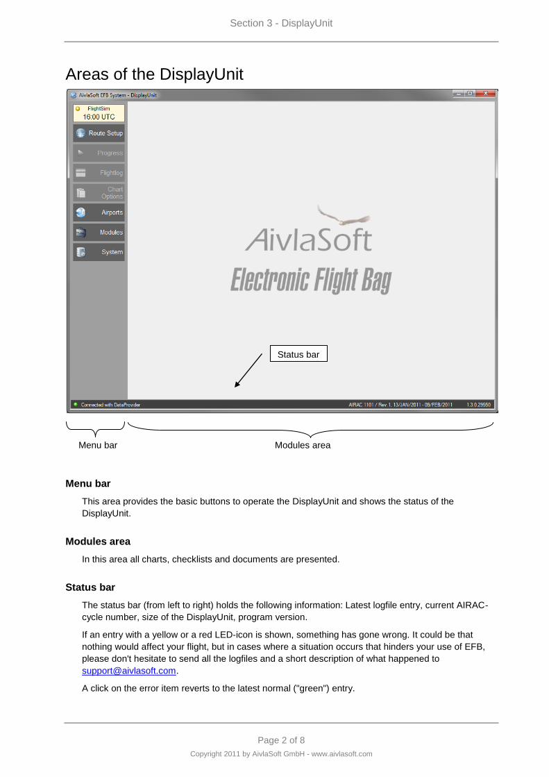
Areas of the DisplayUnit
Menu bar Modules area
Menu bar
This area provides the basic buttons to operate the DisplayUnit and shows the status of the
DisplayUnit.
Modules area
In this area all charts, checklists and documents are presented.
Status bar
The status bar (from left to right) holds the following information: Latest logfile entry, current AIRAC-
cycle number, size of the DisplayUnit, program version.
If an entry with a yellow or a red LED-icon is shown, something has gone wrong. It could be that
nothing would affect your flight, but in cases where a situation occurs that hinders your use of EFB,
please don't hesitate to send all the logfiles and a short description of what happened to
A click on the error item reverts to the latest normal ("green") entry.
Status bar
Section 3 - DisplayUnit
Page 3 of 8
Copyright 2011 by AivlaSoft GmbH - www.aivlasoft.com
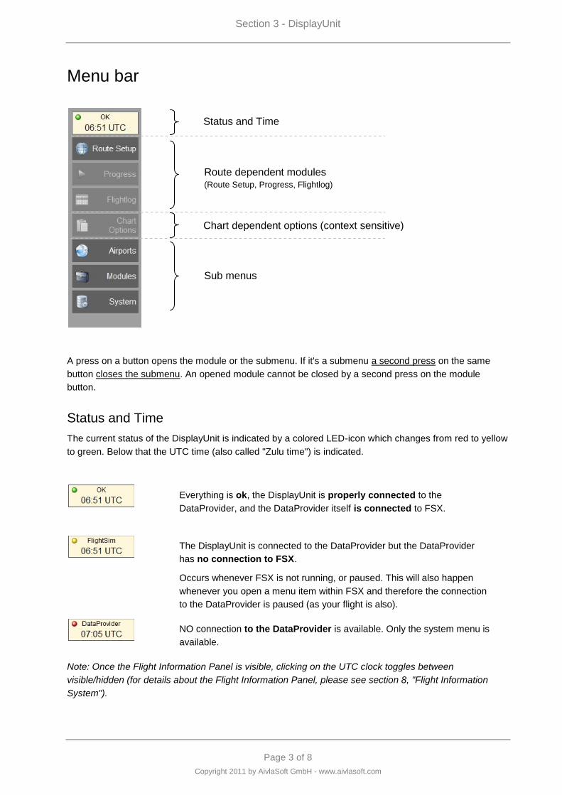
Menu bar
A press on a button opens the module or the submenu. If it's a submenu a second press on the same
button closes the submenu. An opened module cannot be closed by a second press on the module
button.
Status and Time
The current status of the DisplayUnit is indicated by a colored LED-icon which changes from red to yellow
to green. Below that the UTC time (also called "Zulu time") is indicated.
Everything is ok, the DisplayUnit is properly connected to the
DataProvider, and the DataProvider itself is connected to FSX.
The DisplayUnit is connected to the DataProvider but the DataProvider
has no connection to FSX.
Occurs whenever FSX is not running, or paused. This will also happen
whenever you open a menu item within FSX and therefore the connection
to the DataProvider is paused (as your flight is also).
NO connection to the DataProvider is available. Only the system menu is
available.
Note: Once the Flight Information Panel is visible, clicking on the UTC clock toggles between
visible/hidden (for details about the Flight Information Panel, please see section 8, "Flight Information
System").
Status and Time
Route dependent modules (Route Setup, Progress, Flightlog)
Chart dependent options (context sensitive)
Sub menus
Section 3 - DisplayUnit
Page 4 of 8
Copyright 2011 by AivlaSoft GmbH - www.aivlasoft.com
Route dependent modules
Press the "Route Setup" button to load or create a route. As soon as a route has been activated, the
buttons below (Progress and Flightlog) will be available.
Please see the sections "Route Setup (5)", "Progress (6)", and "Flightlog (11)" for further information on
these topics.
Chart dependent options
This "blue" button is a context-sensitive menu button. It's a menu button and the menu items change
according to the selected chart type. This button is enabled as soon as a chart is shown in the modules
area.
Please see the sections "Progress (6)" and "Charts (7)."
Section 3 - DisplayUnit
Page 5 of 8
Copyright 2011 by AivlaSoft GmbH - www.aivlasoft.com
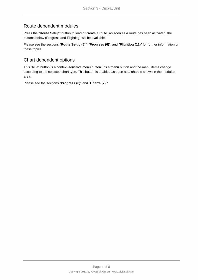
Sub menus
Airports
As long as no route has been activated, most buttons of this
submenu are not available.
The button "All Airports" opens the Airport Database.
Please see the section "Airport Database (4)" for more
information.
As soon as a route has been activated, the submenu
provides some buttons for direct access to all route
relevant airports whereas the Progress Module shows you
all the needed charts for the current route in a chronological
sequence.
The last selected airport (selected from the airports
database) will always appear in this menu. This is for more
convenience if you have to access this airport again.
Section 3 - DisplayUnit
Page 6 of 8
Copyright 2011 by AivlaSoft GmbH - www.aivlasoft.com
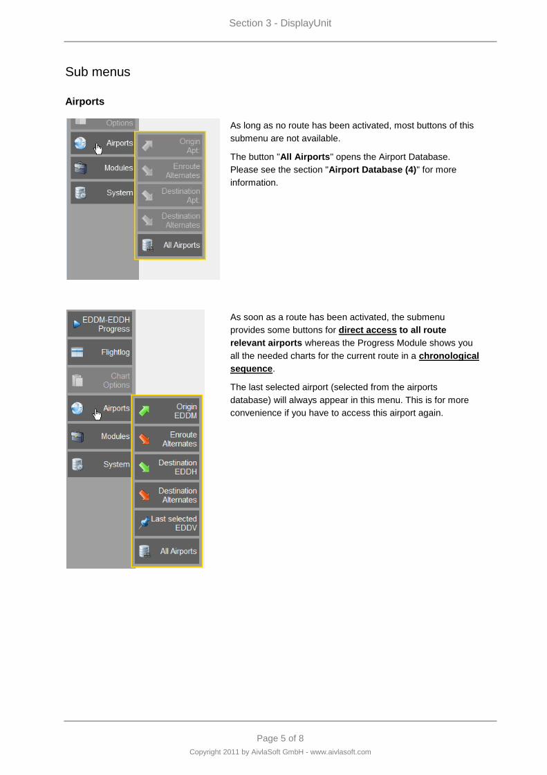
Modules
The Checklists Module provides direct access to all
checklists. For further information on the Checklists Module
please see section "Checklists (12)."
The METAR Module provides textual decoded weather
information from several sources. Details can be found in the
section “METAR (9).”
The Library Module is a collection of documents that can be
referenced in flight. It is further described in section "Library
(13)."
The NOTAMs Module displays a website within the context
of the EFB Display Unit. The URL for this website can be
defined in the Settings.
System
Every press of the "Menu Position" button will change the
position of the menu bar according to the sequence LEFT -
TOP - RIGHT - BOTTOM.
The "Checklist Editor" is the tool for creating and
maintaining the checklists for all aircrafts. Please see the
description of this editor in the section "Checklists (12)."
With the "Aircrafts Editor" you can create and maintain
aircraft data. It's a simple editor with the functions "New,"
"Update" and "Delete." There is no further description of this
editor because its behavior seems to be as simple as
possible.
"Settings" will open the Settings dialog where you can
change various settings of the DisplayUnit. For further
information on the settings please see "Installation and
Configuration" which is described in Section 1.
"Switch off" will disconnect and terminate the DisplayUnit.
It‟s the same as closing the DisplayUnit window. You will be
asked to confirm this action.
Section 3 - DisplayUnit
Page 7 of 8
Copyright 2011 by AivlaSoft GmbH - www.aivlasoft.com
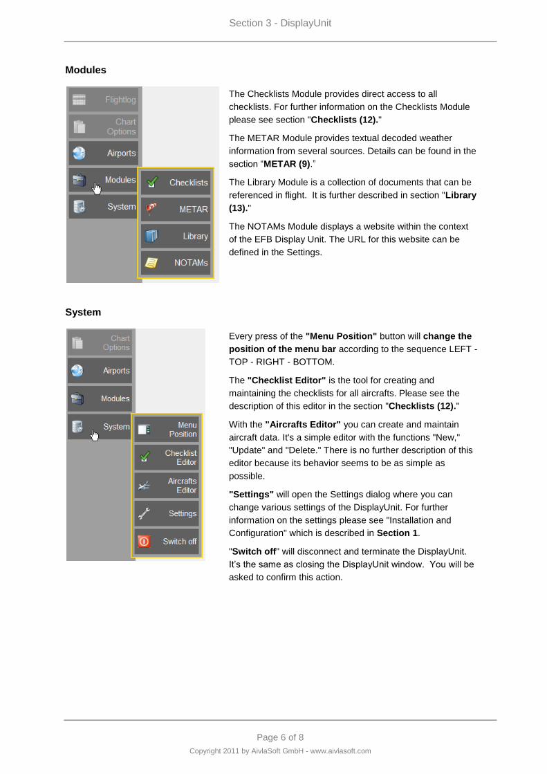
Charts organization
The EFB system provides the charts in two different ways.
A) Route oriented
B) Airport oriented
Route oriented
If a route is activated, the required charts will be usually viewed in the Progress Module. The Progress
Module shows all the required charts in a chronological sequence which is oriented on a typical flight
profile:
Ground chart of the origin airport
Departure chart of the origin airport
Enroute chart from the origin to the destination airport
Arrival chart of the destination airport
Approach chart of the destination airport
Ground chart of the destination airport
Airport oriented
Whether a route is activated or not, the airport oriented view contains all charts from one airport:
Arrival chart
Approach chart
Ground chart
Departure chart
The airport oriented chart view can be selected via the "Airports" menu (Airports > All Airports, or
Airports and then a predefined Airport of the current route). See also page 6 in this section.
Section 3 - DisplayUnit
Page 8 of 8
Copyright 2011 by AivlaSoft GmbH - www.aivlasoft.com
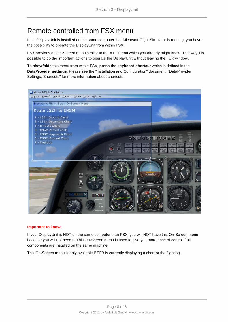
Remote controlled from FSX menu
If the DisplayUnit is installed on the same computer that Microsoft Flight Simulator is running, you have
the possibility to operate the DisplayUnit from within FSX.
FSX provides an On-Screen menu similar to the ATC menu which you already might know. This way it is
possible to do the important actions to operate the DisplayUnit without leaving the FSX window.
To show/hide this menu from within FSX, press the keyboard shortcut which is defined in the
DataProvider settings. Please see the "Installation and Configuration" document, "DataProvider
Settings, Shortcuts" for more information about shortcuts.
Important to know:
If your DisplayUnit is NOT on the same computer than FSX, you will NOT have this On-Screen menu
because you will not need it. This On-Screen menu is used to give you more ease of control if all
components are installed on the same machine.
This On-Screen menu is only available if EFB is currently displaying a chart or the flightlog.

Page 1 of 9
Copyright 2011 by AivlaSoft GmbH - www.aivlasoft.com
Section 4 - Airport Database
Section 4 - Airport Database
Page 2 of 9
Copyright 2011 by AivlaSoft GmbH - www.aivlasoft.com
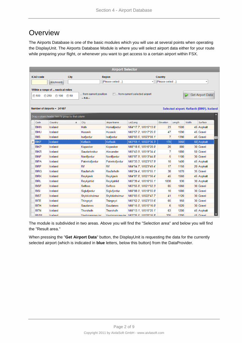
Overview
The Airports Database is one of the basic modules which you will use at several points when operating
the DisplayUnit. The Airports Database Module is where you will select airport data either for your route
while preparing your flight, or whenever you want to get access to a certain airport within FSX.
The module is subdivided in two areas. Above you will find the "Selection area" and below you will find
the "Result area."
When pressing the "Get Airport Data" button, the DisplayUnit is requesting the data for the currently
selected airport (which is indicated in blue letters, below this button) from the DataProvider.
Section 4 - Airport Database
Page 3 of 9
Copyright 2011 by AivlaSoft GmbH - www.aivlasoft.com
Selecting airport data
Selection criteria
You may select your airport by different criteria which can be:
An ICAO airport code.
The name of the nearest city of an airport.
By selecting an ICAO region and country.
From within a range from your current position or the current selected airport.
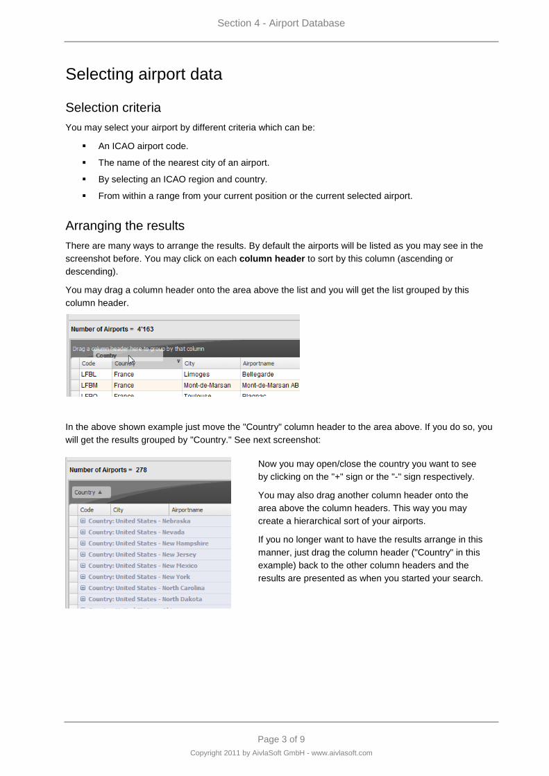
Arranging the results
There are many ways to arrange the results. By default the airports will be listed as you may see in the
screenshot before. You may click on each column header to sort by this column (ascending or
descending).
You may drag a column header onto the area above the list and you will get the list grouped by this
column header.
In the above shown example just move the "Country" column header to the area above. If you do so, you
will get the results grouped by "Country." See next screenshot:
Now you may open/close the country you want to see
by clicking on the "+" sign or the "-" sign respectively.
You may also drag another column header onto the
area above the column headers. This way you may
create a hierarchical sort of your airports.
If you no longer want to have the results arrange in this
manner, just drag the column header ("Country" in this
example) back to the other column headers and the
results are presented as when you started your search.
Section 4 - Airport Database
Page 4 of 9
Copyright 2011 by AivlaSoft GmbH - www.aivlasoft.com
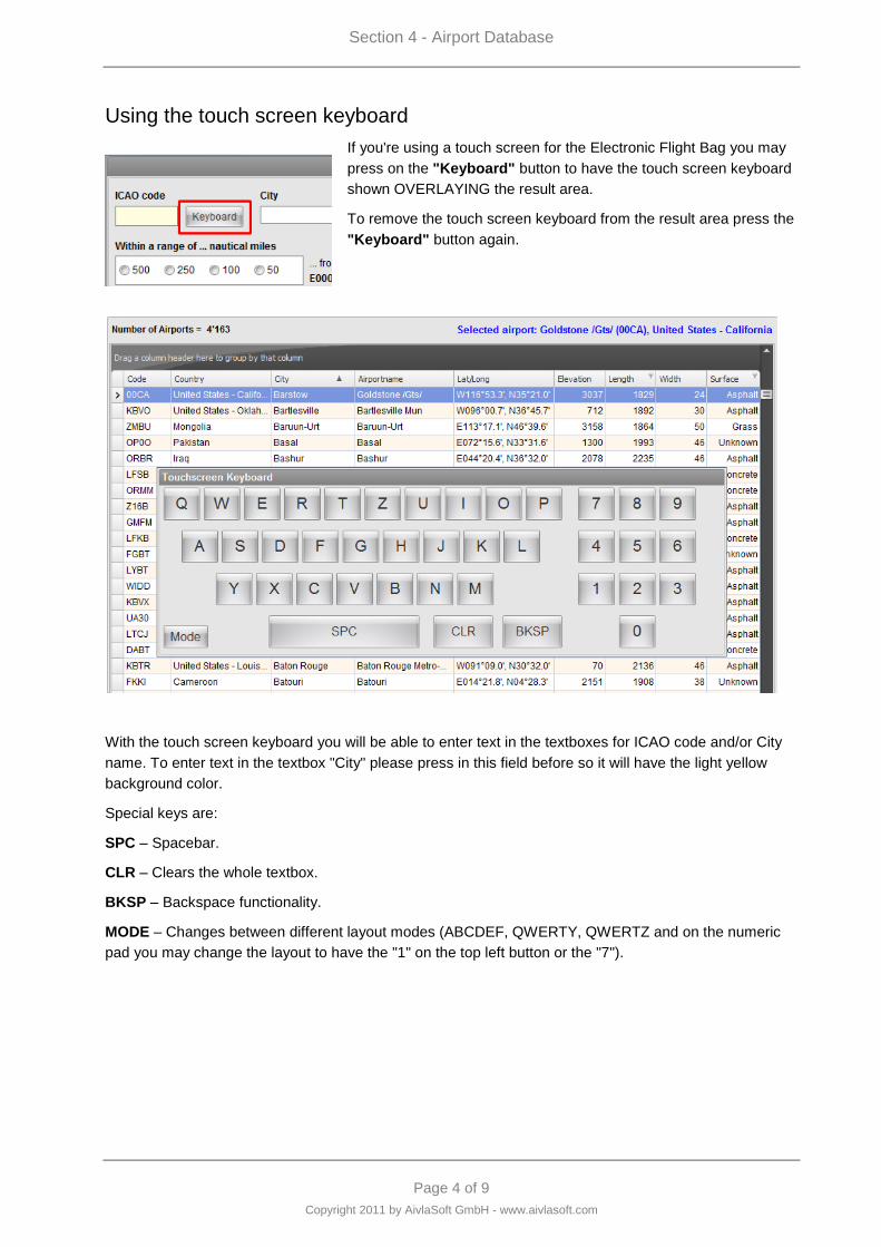
Using the touch screen keyboard
If you're using a touch screen for the Electronic Flight Bag you may
press on the "Keyboard" button to have the touch screen keyboard
shown OVERLAYING the result area.
To remove the touch screen keyboard from the result area press the
"Keyboard" button again.
With the touch screen keyboard you will be able to enter text in the textboxes for ICAO code and/or City
name. To enter text in the textbox "City" please press in this field before so it will have the light yellow
background color.
Special keys are:
SPC – Spacebar.
CLR – Clears the whole textbox.
BKSP – Backspace functionality.
MODE – Changes between different layout modes (ABCDEF, QWERTY, QWERTZ and on the numeric
pad you may change the layout to have the "1" on the top left button or the "7").
Section 4 - Airport Database
Page 5 of 9
Copyright 2011 by AivlaSoft GmbH - www.aivlasoft.com
Custom filters
If you are flying an Airbus A330 or a Boeing 737 or another heavy aircraft, you may not be interested in
small airfields with grass strips or (even worse) landing areas in the water. In this case it's better to create
a custom filter to reduce the results. Of course you may also define a filter if you're flying a Cessna 172
and you don't want to see airports which have runways made of concrete and a length of 2 or more
kilometers …
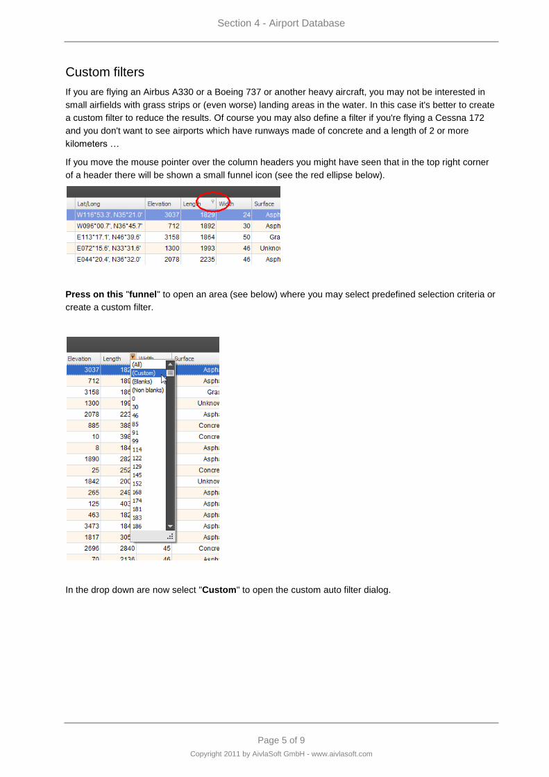
If you move the mouse pointer over the column headers you might have seen that in the top right corner
of a header there will be shown a small funnel icon (see the red ellipse below).
Press on this "funnel" to open an area (see below) where you may select predefined selection criteria or
create a custom filter.
In the drop down are now select "Custom" to open the custom auto filter dialog.
Section 4 - Airport Database
Page 6 of 9
Copyright 2011 by AivlaSoft GmbH - www.aivlasoft.com
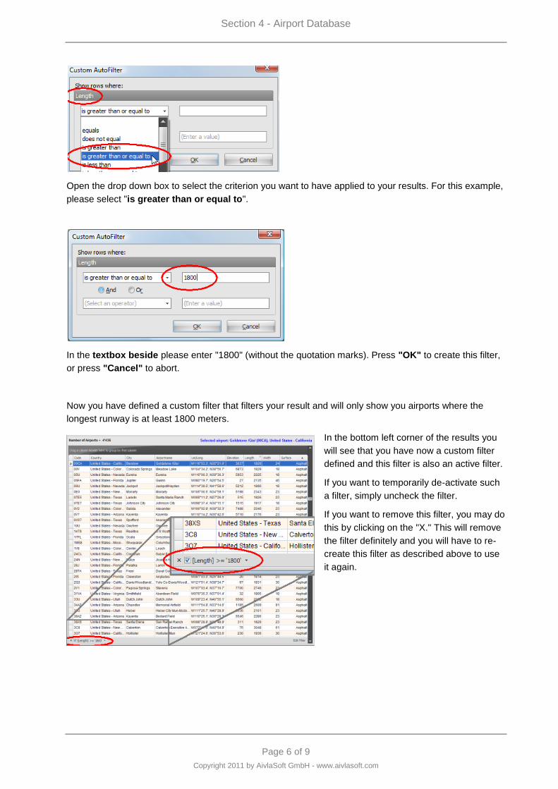
Open the drop down box to select the criterion you want to have applied to your results. For this example,
please select "is greater than or equal to".
In the textbox beside please enter "1800" (without the quotation marks). Press "OK" to create this filter,
or press "Cancel" to abort.
Now you have defined a custom filter that filters your result and will only show you airports where the
longest runway is at least 1800 meters.
In the bottom left corner of the results you
will see that you have now a custom filter
defined and this filter is also an active filter.
If you want to temporarily de-activate such
a filter, simply uncheck the filter.
If you want to remove this filter, you may do
this by clicking on the "X." This will remove
the filter definitely and you will have to re-
create this filter as described above to use
it again.
Section 4 - Airport Database
Page 7 of 9
Copyright 2011 by AivlaSoft GmbH - www.aivlasoft.com
Combining filters
It's also possible to combine filters. If you want to add more restriction to the above defined filter (in case
you are still flying an A330, B737 or anything else you don't want to have all the water landing areas
shown in your results list). Define a new filter criterion by selecting the funnel-icon at the 'Surface'
column header.
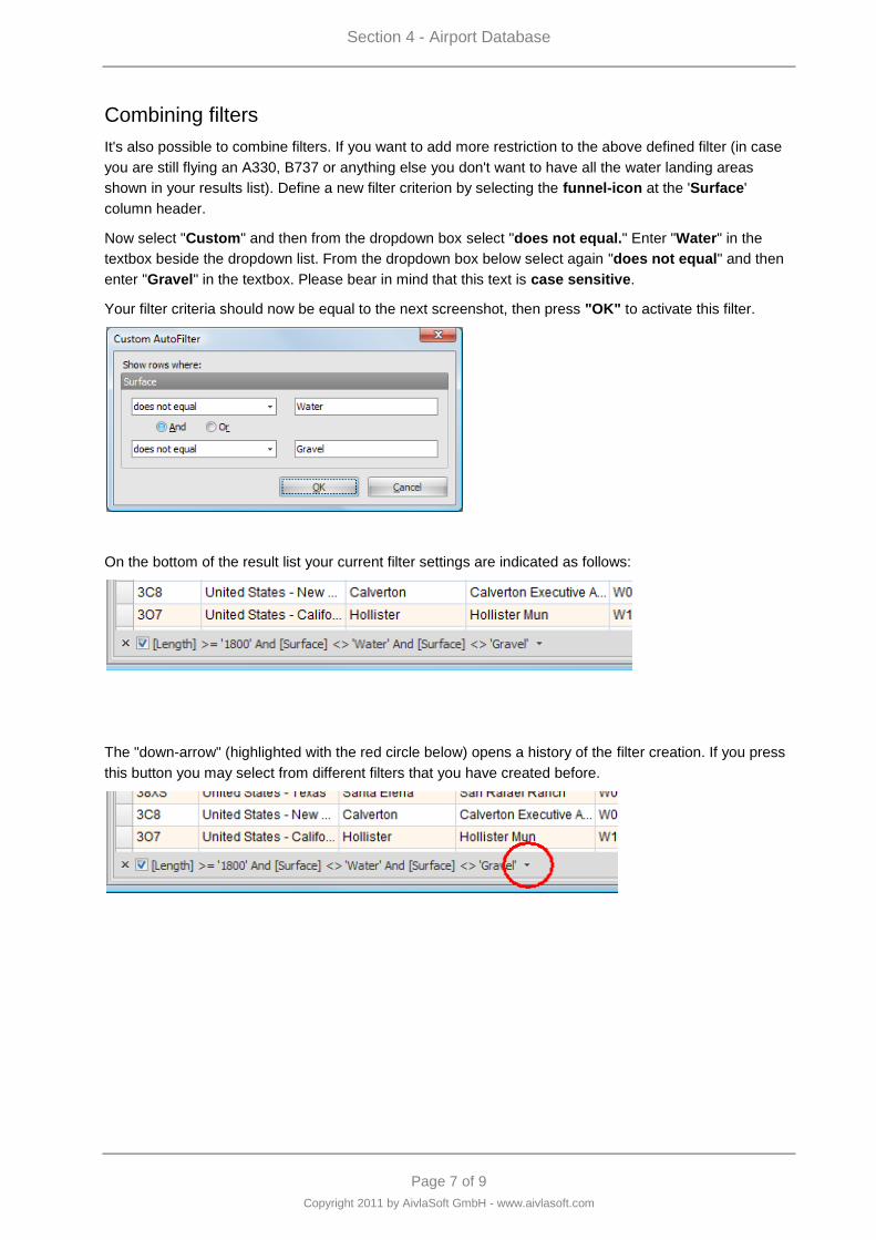
Now select "Custom" and then from the dropdown box select "does not equal." Enter "Water" in the
textbox beside the dropdown list. From the dropdown box below select again "does not equal" and then
enter "Gravel" in the textbox. Please bear in mind that this text is case sensitive.
Your filter criteria should now be equal to the next screenshot, then press "OK" to activate this filter.
On the bottom of the result list your current filter settings are indicated as follows:
The "down-arrow" (highlighted with the red circle below) opens a history of the filter creation. If you press
this button you may select from different filters that you have created before.
Section 4 - Airport Database
Page 8 of 9
Copyright 2011 by AivlaSoft GmbH - www.aivlasoft.com
Edit a custom filter
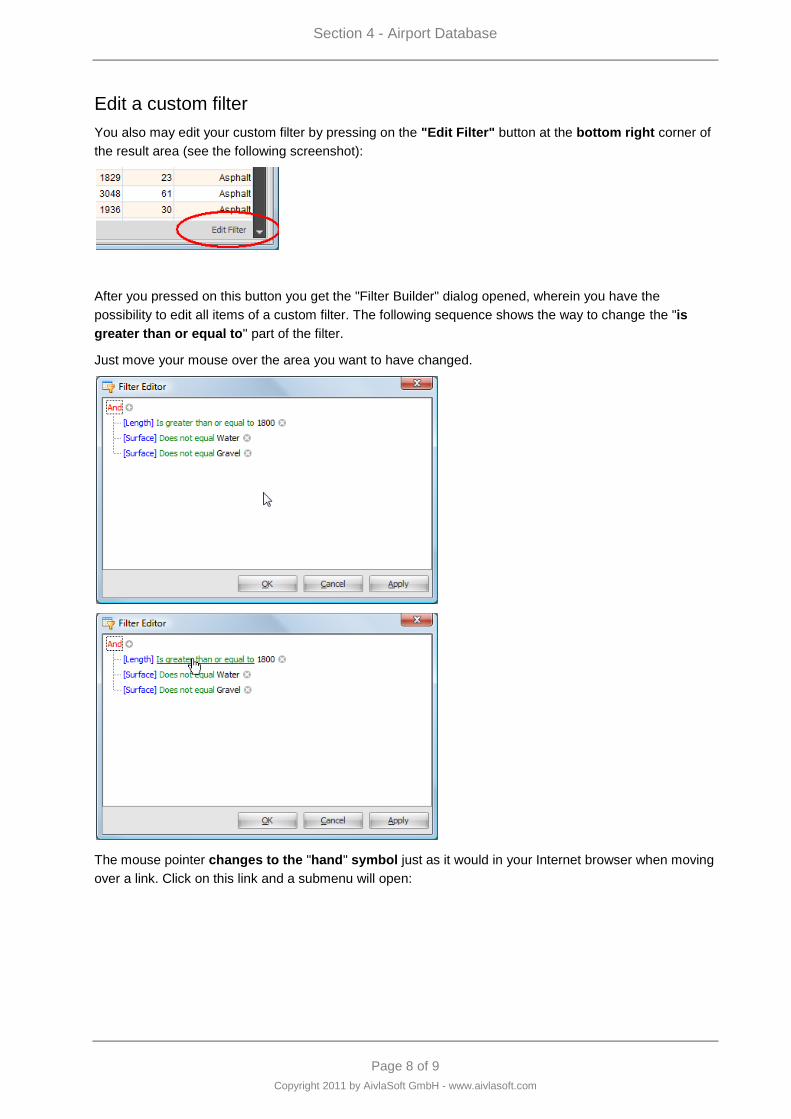
You also may edit your custom filter by pressing on the "Edit Filter" button at the bottom right corner of
the result area (see the following screenshot):
After you pressed on this button you get the "Filter Builder" dialog opened, wherein you have the
possibility to edit all items of a custom filter. The following sequence shows the way to change the "is
greater than or equal to" part of the filter.
Just move your mouse over the area you want to have changed.
The mouse pointer changes to the "hand" symbol just as it would in your Internet browser when moving
over a link. Click on this link and a submenu will open:
Section 4 - Airport Database
Page 9 of 9
Copyright 2011 by AivlaSoft GmbH - www.aivlasoft.com
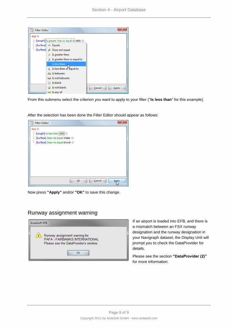
From this submenu select the criterion you want to apply to your filter ("Is less than" for this example).
After the selection has been done the Filter Editor should appear as follows:
Now press "Apply" and/or "OK" to save this change.
Runway assignment warning
If an airport is loaded into EFB, and there is
a mismatch between an FSX runway
designation and the runway designation in
your Navigraph dataset, the Display Unit will
prompt you to check the DataProvider for
details.
Please see the section “DataProvider (2)”
for more information.


Page 1 of 21
Copyright 2011 by AivlaSoft GmbH - www.aivlasoft.com
Section 5 - Route Setup
Section 5 - Route Setup
Page 2 of 21
Copyright 2011 by AivlaSoft GmbH - www.aivlasoft.com
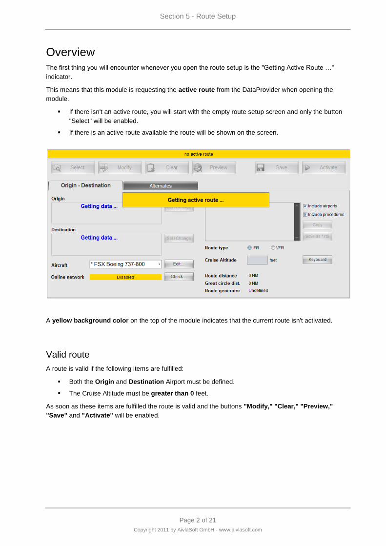
Overview
The first thing you will encounter whenever you open the route setup is the "Getting Active Route …"
indicator.
This means that this module is requesting the active route from the DataProvider when opening the
module.
If there isn't an active route, you will start with the empty route setup screen and only the button
"Select" will be enabled.
If there is an active route available the route will be shown on the screen.
A yellow background color on the top of the module indicates that the current route isn't activated.
Valid route
A route is valid if the following items are fulfilled:
Both the Origin and Destination Airport must be defined.
The Cruise Altitude must be greater than 0 feet.
As soon as these items are fulfilled the route is valid and the buttons "Modify," "Clear," "Preview,"
"Save" and "Activate" will be enabled.
Section 5 - Route Setup
Page 3 of 21
Copyright 2011 by AivlaSoft GmbH - www.aivlasoft.com
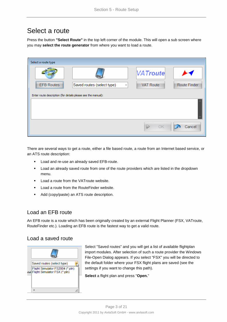
Select a route
Press the button "Select Route" in the top left corner of the module. This will open a sub screen where
you may select the route generator from where you want to load a route.
There are several ways to get a route, either a file based route, a route from an Internet based service, or
an ATS route description:
Load and re-use an already saved EFB-route.
Load an already saved route from one of the route providers which are listed in the dropdown
menu.
Load a route from the VATroute website.
Load a route from the RouteFinder website.
Add (copy/paste) an ATS route description.
Load an EFB route
An EFB route is a route which has been originally created by an external Flight Planner (FSX, VATroute,
RouteFinder etc.). Loading an EFB route is the fastest way to get a valid route.
Load a saved route
Select "Saved routes" and you will get a list of available flightplan
import modules. After selection of such a route provider the Windows
File-Open Dialog appears. If you select "FSX" you will be directed to
the default folder where your FSX flight plans are saved (see the
settings if you want to change this path).
Select a flight plan and press "Open."
Section 5 - Route Setup
Page 4 of 21
Copyright 2011 by AivlaSoft GmbH - www.aivlasoft.com
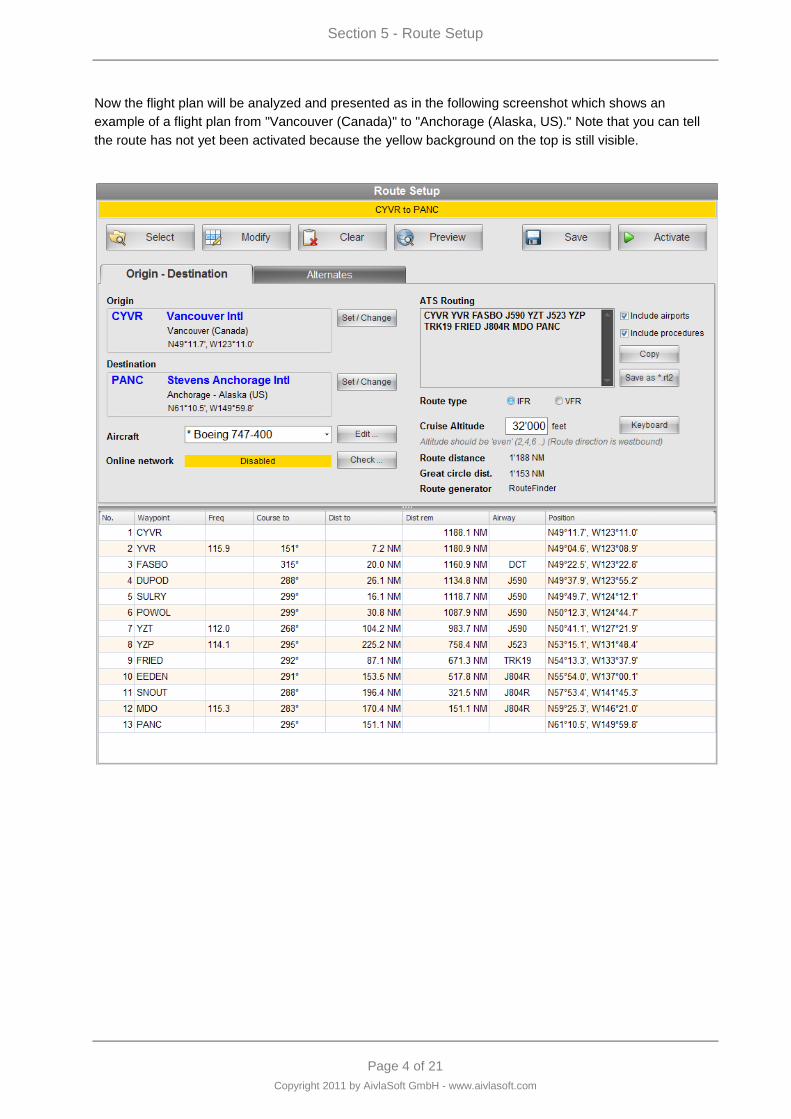
Now the flight plan will be analyzed and presented as in the following screenshot which shows an
example of a flight plan from "Vancouver (Canada)" to "Anchorage (Alaska, US)." Note that you can tell
the route has not yet been activated because the yellow background on the top is still visible.
Section 5 - Route Setup
Page 5 of 21
Copyright 2011 by AivlaSoft GmbH - www.aivlasoft.com
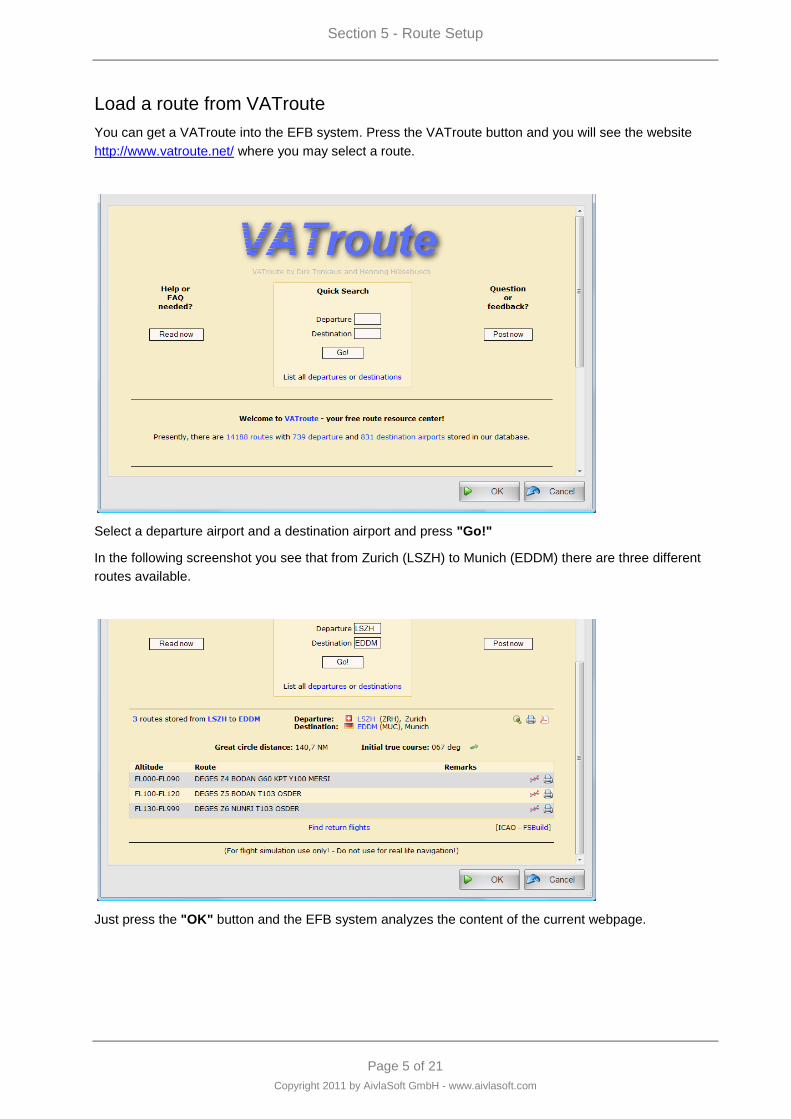
Load a route from VATroute
You can get a VATroute into the EFB system. Press the VATroute button and you will see the website
http://www.vatroute.net/ where you may select a route.
Select a departure airport and a destination airport and press "Go!"
In the following screenshot you see that from Zurich (LSZH) to Munich (EDDM) there are three different
routes available.
Just press the "OK" button and the EFB system analyzes the content of the current webpage.
Section 5 - Route Setup
Page 6 of 21
Copyright 2011 by AivlaSoft GmbH - www.aivlasoft.com
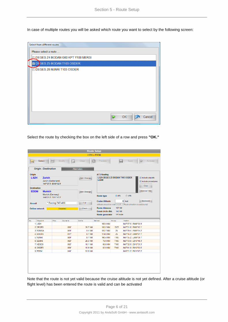
In case of multiple routes you will be asked which route you want to select by the following screen:
Select the route by checking the box on the left side of a row and press "OK."
Note that the route is not yet valid because the cruise altitude is not yet defined. After a cruise altitude (or
flight level) has been entered the route is valid and can be activated
Section 5 - Route Setup
Page 7 of 21
Copyright 2011 by AivlaSoft GmbH - www.aivlasoft.com
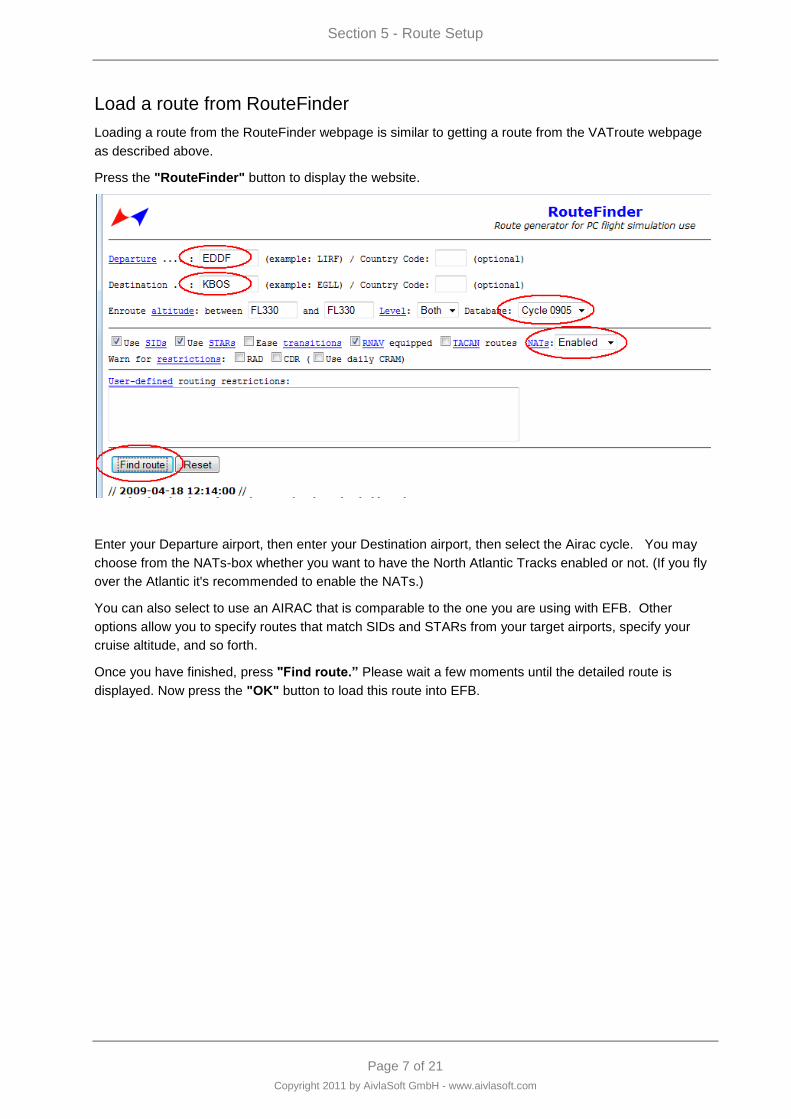
Load a route from RouteFinder
Loading a route from the RouteFinder webpage is similar to getting a route from the VATroute webpage
as described above.
Press the "RouteFinder" button to display the website.
Enter your Departure airport, then enter your Destination airport, then select the Airac cycle. You may
choose from the NATs-box whether you want to have the North Atlantic Tracks enabled or not. (If you fly
over the Atlantic it's recommended to enable the NATs.)
You can also select to use an AIRAC that is comparable to the one you are using with EFB. Other
options allow you to specify routes that match SIDs and STARs from your target airports, specify your
cruise altitude, and so forth.
Once you have finished, press "Find route.” Please wait a few moments until the detailed route is
displayed. Now press the "OK" button to load this route into EFB.
Section 5 - Route Setup
Page 8 of 21
Copyright 2011 by AivlaSoft GmbH - www.aivlasoft.com
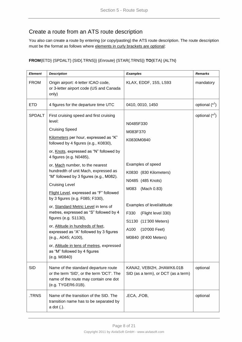
Create a route from an ATS route description
You also can create a route by entering (or copy/pasting) the ATS route description. The route description
must be the format as follows where elements in curly brackets are optional:
FROM{ETD} {SPDALT} {SID{.TRNS}} {Enroute} {STAR{.TRNS}} TO{ETA} {ALTN}
Element Description Examples Remarks
FROM Origin airport: 4-letter ICAO code,
or 3-letter airport code (US and Canada
only)
KLAX, EDDF, 15S, LS93 mandatory
ETD 4 figures for the departure time UTC 0410, 0010, 1450 optional (*1)
SPDALT First cruising speed and first cruising
level:
Cruising Speed
Kilometers per hour, expressed as “K”
followed by 4 figures (e.g., K0830),
or, Knots, expressed as “N” followed by
4 figures (e.g. N0485),
or, Mach number, to the nearest
hundredth of unit Mach, expressed as
“M” followed by 3 figures (e.g., M082).
Cruising Level
Flight Level, expressed as “F” followed
by 3 figures (e.g. F085; F330),
or, Standard Metric Level in tens of
metres, expressed as “S” followed by 4
figures (e.g. S1130),
or, Altitude in hundreds of feet,
expressed as “A” followed by 3 figures
(e.g., A045; A100),
or, Altitude in tens of metres, expressed
as “M” followed by 4 figures
(e.g. M0840)
N0485F330
M083F370
K0830M0840
Examples of speed
K0830 (830 Kilometers)
N0485 (485 Knots)
M083 (Mach 0.83)
Examples of level/altitude
F330 (Flight level 330)
S1130 (11'300 Meters)
A100 (10'000 Feet)
M0840 (8'400 Meters)
optional (*2)
SID Name of the standard departure route
or the term 'SID', or the term 'DCT'. The
name of the route may contain one dot
(e.g. TYGER6.01B).
KANA2, VEBI2H, JHAWK6.01B
SID (as a term), or DCT (as a term)
optional
.TRNS Name of the transition of the SID. The
transition name has to be separated by
a dot (.).
.ECA, .FOB, optional
Section 5 - Route Setup
Page 9 of 21
Copyright 2011 by AivlaSoft GmbH - www.aivlasoft.com
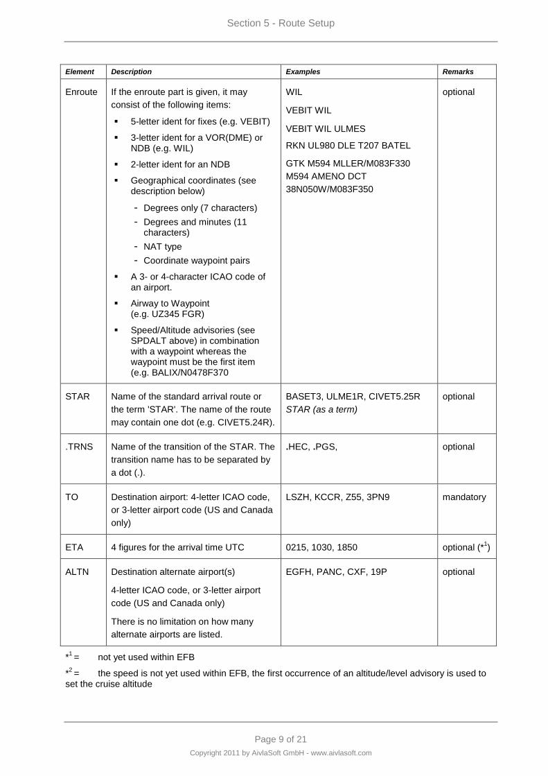
Element Description Examples Remarks
Enroute If the enroute part is given, it may
consist of the following items:
5-letter ident for fixes (e.g. VEBIT)
3-letter ident for a VOR(DME) or NDB (e.g. WIL)
2-letter ident for an NDB
Geographical coordinates (see description below)
- Degrees only (7 characters)
- Degrees and minutes (11 characters)
- NAT type
- Coordinate waypoint pairs
A 3- or 4-character ICAO code of an airport.
Airway to Waypoint (e.g. UZ345 FGR)
Speed/Altitude advisories (see SPDALT above) in combination with a waypoint whereas the waypoint must be the first item (e.g. BALIX/N0478F370
WIL
VEBIT WIL
VEBIT WIL ULMES
RKN UL980 DLE T207 BATEL
GTK M594 MLLER/M083F330
M594 AMENO DCT
38N050W/M083F350
optional
STAR Name of the standard arrival route or
the term 'STAR'. The name of the route
may contain one dot (e.g. CIVET5.24R).
BASET3, ULME1R, CIVET5.25R
STAR (as a term)
optional
.TRNS Name of the transition of the STAR. The
transition name has to be separated by
a dot (.).
.HEC, .PGS, optional
TO Destination airport: 4-letter ICAO code,
or 3-letter airport code (US and Canada
only)
LSZH, KCCR, Z55, 3PN9 mandatory
ETA 4 figures for the arrival time UTC 0215, 1030, 1850 optional (*1)
ALTN Destination alternate airport(s)
4-letter ICAO code, or 3-letter airport
code (US and Canada only)
There is no limitation on how many
alternate airports are listed.
EGFH, PANC, CXF, 19P optional
*1 = not yet used within EFB
*2 = the speed is not yet used within EFB, the first occurrence of an altitude/level advisory is used to
set the cruise altitude
Section 5 - Route Setup
Page 10 of 21
Copyright 2011 by AivlaSoft GmbH - www.aivlasoft.com
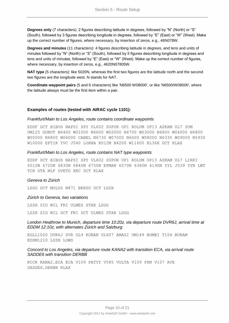
Degrees only (7 characters): 2 figures describing latitude in degrees, followed by “N” (North) or “S”
(South), followed by 3 figures describing longitude in degrees, followed by “E” (East) or “W” (West). Make
up the correct number of figures, where necessary, by insertion of zeros, e.g., 46N078W.
Degrees and minutes (11 characters): 4 figures describing latitude in degrees, and tens and units of
minutes followed by “N” (North) or “S” (South), followed by 5 figures describing longitude in degrees and
tens and units of minutes, followed by “E” (East) or “W” (West). Make up the correct number of figures,
where necessary, by insertion of zeros, e.g., 4620N07805W.
NAT type (5 characters): like 5020N, whereas the first two figures are the latitude north and the second
two figures are the longitude west. N stands for NAT.
Coordinate waypoint pairs (5 and 6 characters) like 'N6500 W08000', or like 'N6500/W08000', where
the latitude always must be the first item within a pair.
Examples of routes (tested with AIRAC cycle 1101):
Frankfurt/Main to Los Angeles, route contains coordinate waypoints
EDDF DCT BIBOS NAPSI SPY UL602 SUPUR UP1 ROLUM UP13 ASKAM UL7 SUM
UM125 GONUT N6400 W01000 N6600 W02000 N6700 W03000 N6800 W04000 N6800
W05000 N6800 W06000 CANEL N6730 W07000 N6600 W08000 N6330 W09000 N5930
W10000 EPTIR YVC J540 LORNA KU12M N4200 W11600 KL36K DCT KLAX
Frankfurt/Main to Los Angeles, route contains NAT type waypoints
EDDF DCT BIBOS NAPSI SPY UL602 SUPUR UP1 ROLUM UP13 ASKAM UL7 LIRKI
6510N 6720N 6830N 6840N 6750N EPMAN 6570N 6380N 6190N YYL J539 YYN LWT
TCH DTA MLF OVETO HEC DCT KLAX
Geneva to Zürich
LSGG DCT MOLUS N871 BERSU DCT LSZH
Zürich to Geneva, two variations
LSZH SID WIL FRI ULMES STAR LSGG
LSZH SID WIL DCT FRI DCT ULMES STAR LSGG
London Heathrow to Munich, departure time 10:20z, via departure route DVR6J, arrival time at EDDM 12:10z, with alternates Zürich and Salzburg
EGLL1020 DVR6J DVR UL9 KONAN UL607 AMASI UM149 BOMBI T104 BURAM
EDDM1210 LSZH LOWS
Concord to Los Angeles, via departure route KANA2 with transition ECA, via arrival route SADDE6 with transition DERBB
KCCR KANA2.ECA ECA V109 PATYY V585 VOLTA V109 PXN V107 AVE
SADDE6.DERBB KLAX

Section 5 - Route Setup
Page 11 of 21
Copyright 2011 by AivlaSoft GmbH - www.aivlasoft.com
Kingston to Trondheim, via departure route MLY5, initial cruise level FL320, alternate is Orland
MKJP N0494F320 MLY5 MLY UG633 BENET/N0492F330 UB882 GTK M594
MLLER/M083F330 M594 AMENO DCT 38N050W/M083F350 47N040W
53N030W/M083F370 57N020W DCT BALIX/N0478F370 UP59 NINEX UN593 BAMRA
UN584 SUM UP612 FLS UZ108 LASAG ENVA ENOL
Boston to Los Angeles, via departure route WYLYY7, transition BOSOX, and arrival route CIVET5.25L, transition PGS
KBOS WYLYY7.BOSOX ALB J82 JHW J554 GIJ J146 JOT J18 ALBRT J64 TBC J128
PGS CIVET5.25L.PGS KLAX
Section 5 - Route Setup
Page 12 of 21
Copyright 2011 by AivlaSoft GmbH - www.aivlasoft.com
Create a simple route
Not every time you fly will you want to fly along a predefined route. For these times, you may also create
a simple route.
The way to create such a simple route is like this:
select an origin airport (press "Set Origin")
select a destination airport (press "Set Destination")
Set your cruise altitude
Press "Activate"
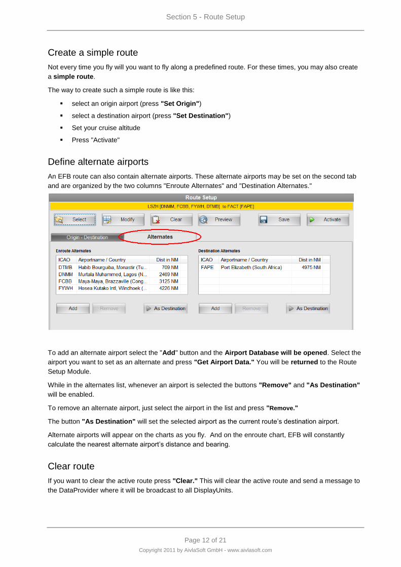
Define alternate airports
An EFB route can also contain alternate airports. These alternate airports may be set on the second tab
and are organized by the two columns "Enroute Alternates" and "Destination Alternates."
To add an alternate airport select the "Add" button and the Airport Database will be opened. Select the
airport you want to set as an alternate and press "Get Airport Data." You will be returned to the Route
Setup Module.
While in the alternates list, whenever an airport is selected the buttons "Remove" and "As Destination"
will be enabled.
To remove an alternate airport, just select the airport in the list and press "Remove."
The button "As Destination" will set the selected airport as the current route‟s destination airport.
Alternate airports will appear on the charts as you fly. And on the enroute chart, EFB will constantly
calculate the nearest alternate airport‟s distance and bearing.
Clear route
If you want to clear the active route press "Clear." This will clear the active route and send a message to
the DataProvider where it will be broadcast to all DisplayUnits.
Section 5 - Route Setup
Page 13 of 21
Copyright 2011 by AivlaSoft GmbH - www.aivlasoft.com
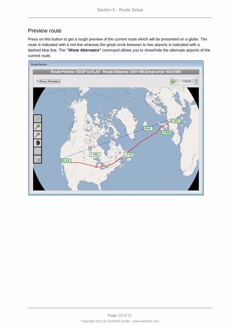
Preview route
Press on this button to get a rough preview of the current route which will be presented on a globe. The
route is indicated with a red line whereas the great circle between to two airports is indicated with a
dashed blue line. The "Show Alternates" command allows you to show/hide the alternate airports of the
current route.
Section 5 - Route Setup
Page 14 of 21
Copyright 2011 by AivlaSoft GmbH - www.aivlasoft.com
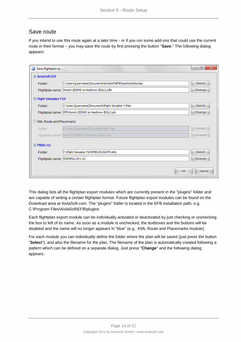
Save route
If you intend to use this route again at a later time - or if you run some add-ons that could use the current
route in their format – you may save the route by first pressing the button "Save." The following dialog
appears:
This dialog lists all the flightplan export modules which are currently present in the "plugins" folder and
are capable of writing a certain flightplan format. Future flightplan export modules can be found on the
Download area at AivlaSoft.com. The "plugins" folder is located in the EFB installation path, e.g.
C:\Program Files\AivlaSoft\EFB\plugins
Each flightplan export module can be individually activated or deactivated by just checking or unchecking
the box to left of its name. As soon as a module is unchecked, the textboxes and the buttons will be
disabled and the name will no longer appears in "blue" (e.g., KML Route and Placemarks module).
For each module you can individually define the folder where the plan will be saved (just press the button
"Select"), and also the filename for the plan. The filename of the plan is automatically created following a
pattern which can be defined on a separate dialog. Just press "Change" and the following dialog
appears:
Section 5 - Route Setup
Page 15 of 21
Copyright 2011 by AivlaSoft GmbH - www.aivlasoft.com
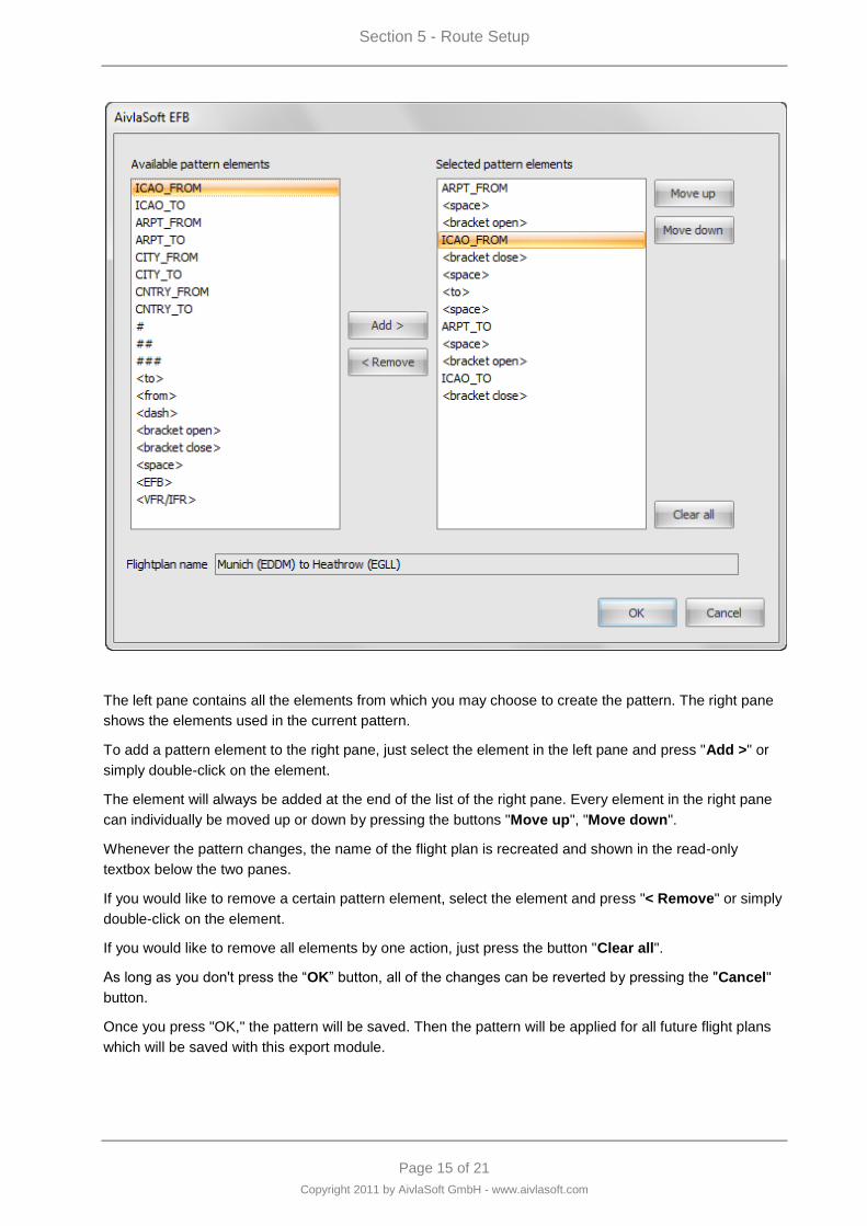
The left pane contains all the elements from which you may choose to create the pattern. The right pane
shows the elements used in the current pattern.
To add a pattern element to the right pane, just select the element in the left pane and press "Add >" or
simply double-click on the element.
The element will always be added at the end of the list of the right pane. Every element in the right pane
can individually be moved up or down by pressing the buttons "Move up", "Move down".
Whenever the pattern changes, the name of the flight plan is recreated and shown in the read-only
textbox below the two panes.
If you would like to remove a certain pattern element, select the element and press "< Remove" or simply
double-click on the element.
If you would like to remove all elements by one action, just press the button "Clear all".
As long as you don't press the “OK” button, all of the changes can be reverted by pressing the "Cancel"
button.
Once you press "OK," the pattern will be saved. Then the pattern will be applied for all future flight plans
which will be saved with this export module.
Section 5 - Route Setup
Page 16 of 21
Copyright 2011 by AivlaSoft GmbH - www.aivlasoft.com
The meaning of the elements:
ICAO_FROM 4-letter ICAO code of origin airport
ICAO_TO 4-letter ICAO code of destination airport
ARPT_FROM Name of origin airport
ARPT_TO Name of destination airport
CITY_FROM Nearest city from origin airport
CITY_TO Nearest city from destination airport
CNTRY_FROM Country of origin airport
CNTRY_TO Country of destination airport
# next number (0 - 9), one digit
## next number (00 - 99), two digits
### next number (000 - 999), three digits
<to> "to"
<from> "From"
<dash> "-"
<bracket open> "("
<bracket close> ")"
<space> " " (space)
<EFB> "EFB"
<VFR/IFR> "VFR" or "IFR", according to the route type
Activate route
Press the "Activate" button to send this route to the DataProvider as the active route. Every DisplayUnit
which is connected to the DataProvider will now recognize this route as the active one.
When activating the route, the DataProvider will also create a new flight log and - if this option is selected
in the current settings - save the route as an FSX route as well.
The option "Create Garmin GPS flight plans" in the DisplayUnit‟s settings allows the DataProvider to load
the route into the Garmin GPS as the active flight plan if the DataProvider is connected to FSX when the
route is activated.
After activation of the route the Progress Module will be activated automatically.
Modify route
With this sub module you have the possibility to enhance your already defined route by inserting:
Standard Departure Routes (SID)
Standard Terminal Arrival Routes (STAR)
Approaches
Enroute waypoints
Section 5 - Route Setup
Page 17 of 21
Copyright 2011 by AivlaSoft GmbH - www.aivlasoft.com
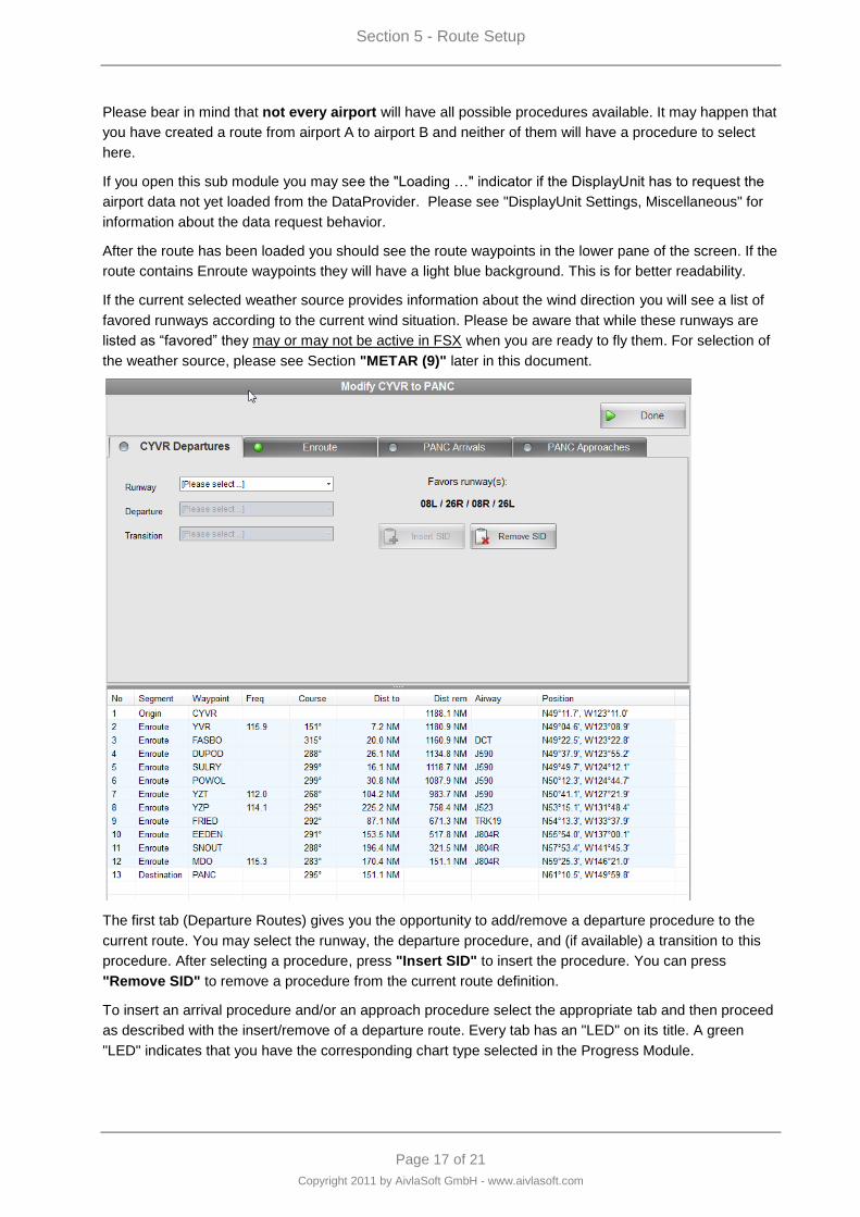
Please bear in mind that not every airport will have all possible procedures available. It may happen that
you have created a route from airport A to airport B and neither of them will have a procedure to select
here.
If you open this sub module you may see the "Loading …" indicator if the DisplayUnit has to request the
airport data not yet loaded from the DataProvider. Please see "DisplayUnit Settings, Miscellaneous" for
information about the data request behavior.
After the route has been loaded you should see the route waypoints in the lower pane of the screen. If the
route contains Enroute waypoints they will have a light blue background. This is for better readability.
If the current selected weather source provides information about the wind direction you will see a list of
favored runways according to the current wind situation. Please be aware that while these runways are
listed as “favored” they may or may not be active in FSX when you are ready to fly them. For selection of
the weather source, please see Section "METAR (9)" later in this document.
The first tab (Departure Routes) gives you the opportunity to add/remove a departure procedure to the
current route. You may select the runway, the departure procedure, and (if available) a transition to this
procedure. After selecting a procedure, press "Insert SID" to insert the procedure. You can press
"Remove SID" to remove a procedure from the current route definition.
To insert an arrival procedure and/or an approach procedure select the appropriate tab and then proceed
as described with the insert/remove of a departure route. Every tab has an "LED" on its title. A green
"LED" indicates that you have the corresponding chart type selected in the Progress Module.
Section 5 - Route Setup
Page 18 of 21
Copyright 2011 by AivlaSoft GmbH - www.aivlasoft.com
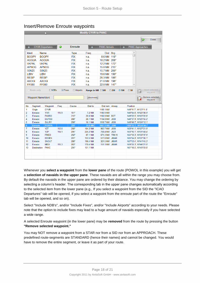
Insert/Remove Enroute waypoints
Whenever you select a waypoint from the lower pane of the route (POWOL in this example) you will get
a selection of navaids in the upper pane. These navaids are all within the range you may choose from.
By default the navaids in the upper pane are ordered by their distance. You may change the ordering by
selecting a column‟s header. The corresponding tab in the upper pane changes automatically according
to the selected item from the lower pane (e.g., If you select a waypoint from the SID the "ICAO
Departures" tab will be opened, if you select a waypoint from the enroute part of the route the "Enroute"
tab will be opened, and so on).
Select "Include NDB's", and/or "Include Fixes", and/or "Include Airports" according to your needs. Please
note that the option to include fixes may lead to a huge amount of navaids especially if you have selected
a wide range.
A selected Enroute waypoint (in the lower pane) may be removed from the route by pressing the button
"Remove selected waypoint."
You may NOT remove a waypoint from a STAR nor from a SID nor from an APPROACH. These
predefined route-segments are STANDARD (hence their names) and cannot be changed. You would
have to remove the entire segment, or leave it as part of your route.
Section 5 - Route Setup
Page 19 of 21
Copyright 2011 by AivlaSoft GmbH - www.aivlasoft.com
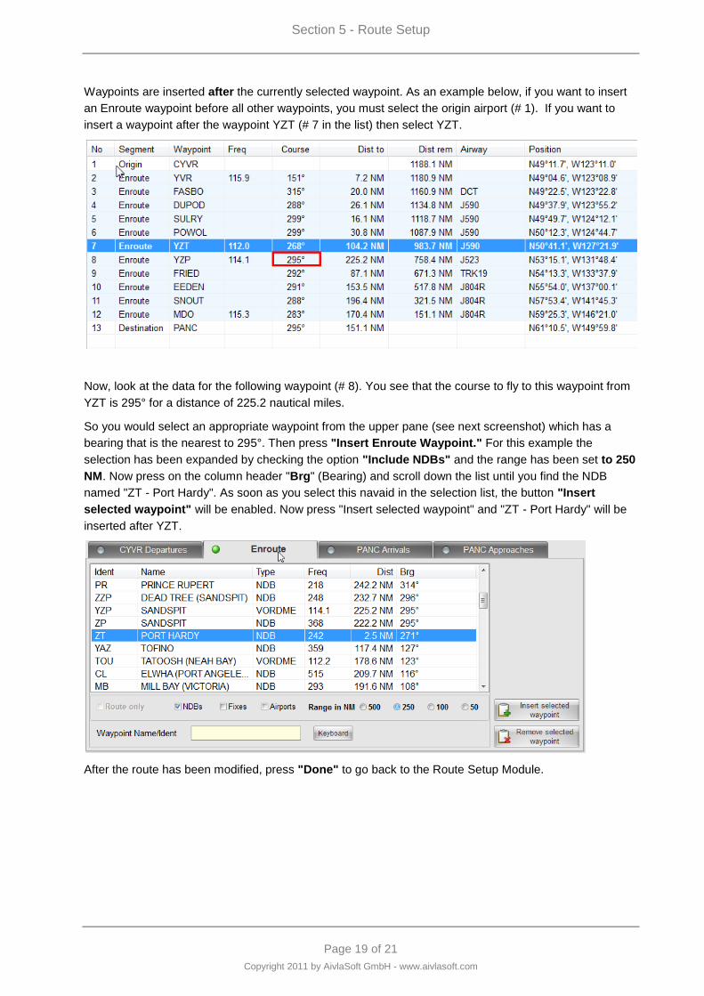
Waypoints are inserted after the currently selected waypoint. As an example below, if you want to insert
an Enroute waypoint before all other waypoints, you must select the origin airport (# 1). If you want to
insert a waypoint after the waypoint YZT (# 7 in the list) then select YZT.
Now, look at the data for the following waypoint (# 8). You see that the course to fly to this waypoint from
YZT is 295° for a distance of 225.2 nautical miles.
So you would select an appropriate waypoint from the upper pane (see next screenshot) which has a
bearing that is the nearest to 295°. Then press "Insert Enroute Waypoint." For this example the
selection has been expanded by checking the option "Include NDBs" and the range has been set to 250
NM. Now press on the column header "Brg" (Bearing) and scroll down the list until you find the NDB
named "ZT - Port Hardy". As soon as you select this navaid in the selection list, the button "Insert
selected waypoint" will be enabled. Now press "Insert selected waypoint" and "ZT - Port Hardy" will be
inserted after YZT.
After the route has been modified, press "Done" to go back to the Route Setup Module.
Section 5 - Route Setup
Page 20 of 21
Copyright 2011 by AivlaSoft GmbH - www.aivlasoft.com
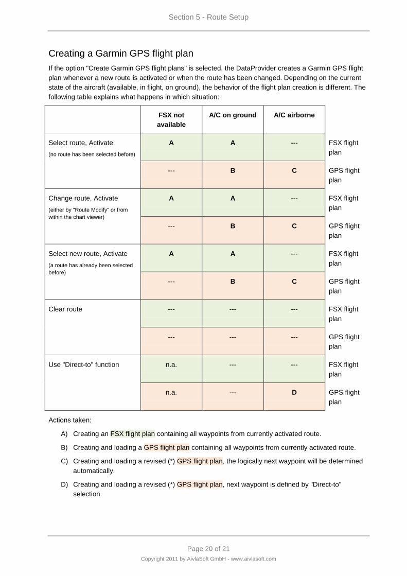
Creating a Garmin GPS flight plan
If the option "Create Garmin GPS flight plans" is selected, the DataProvider creates a Garmin GPS flight
plan whenever a new route is activated or when the route has been changed. Depending on the current
state of the aircraft (available, in flight, on ground), the behavior of the flight plan creation is different. The
following table explains what happens in which situation:
FSX not
available
A/C on ground A/C airborne
Select route, Activate
(no route has been selected before)
A A --- FSX flight
plan
--- B C GPS flight
plan
Change route, Activate
(either by "Route Modify" or from
within the chart viewer)
A A --- FSX flight
plan
--- B C GPS flight
plan
Select new route, Activate
(a route has already been selected
before)
A A --- FSX flight
plan
--- B C GPS flight
plan
Clear route --- --- --- FSX flight
plan
--- --- --- GPS flight
plan
Use "Direct-to" function n.a. --- --- FSX flight
plan
n.a. --- D GPS flight
plan
Actions taken:
A) Creating an FSX flight plan containing all waypoints from currently activated route.
B) Creating and loading a GPS flight plan containing all waypoints from currently activated route.
C) Creating and loading a revised (*) GPS flight plan, the logically next waypoint will be determined
automatically.
D) Creating and loading a revised (*) GPS flight plan, next waypoint is defined by "Direct-to"
selection.
Section 5 - Route Setup
Page 21 of 21
Copyright 2011 by AivlaSoft GmbH - www.aivlasoft.com
(*) Revised GPS flight plan:
1. First, EFB searches for the last waypoint that has been passed.
2. All waypoints before (and including) this last passed waypoint will be dropped.
3. A new waypoint is created, called "PRVPOS" (previous position). This waypoint is the first
waypoint in the new revised GPS flight plan.
4a Alternative to 4b) The next waypoint will be determined. Beginning with the first waypoint that
has not yet been passed, EFB checks whether the aircraft is within a sector of +/- 65° to this
waypoint. If it is within this sector, the waypoint will be taken as the next waypoint. If the aircraft
is not within this sector, the next waypoint will be checked. This repeats until the end of the
flightplan.
4b Alternative to 4a) If the pilot is using the "Direct-to" function and the selected waypoint is part of
the current flightplan, the selected waypoint will be taken as the "next" waypoint. If the selected
waypoint is not part of the flightplan, then the waypoint will also be taken as the next waypoint
but additionally a warning box will be shown for 3 seconds, because selecting a waypoint that is
not part of the current flight plan may cause a strange routing.
5. All remaining waypoints from the current flight plan will be taken over and will be appended
after the "next" waypoint.
In order for flight plans to be loaded by the Garmin GPS unit, you must have both your DataProvider‟s
and DisplayUnit‟s FSX Flightplans folder set to the location of the default FSX flight plan folder in your
computer‟s “\Documents\” or “\My Documents\” folder. Please see the “EFB Installation and
Configuration” manual, Section Configuration (3) for details.


Page 1 of 6
Copyright 2011 by AivlaSoft GmbH - www.aivlasoft.com
Section 6 - Progress
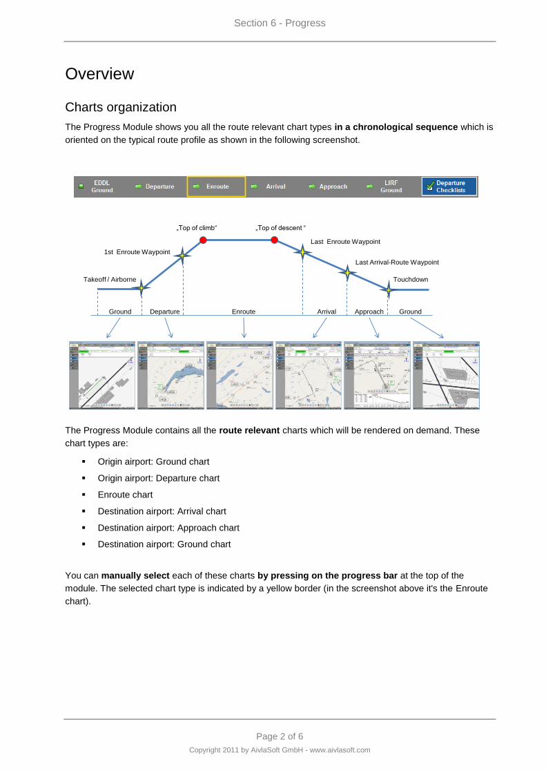
Section 6 - Progress
Page 2 of 6
Copyright 2011 by AivlaSoft GmbH - www.aivlasoft.com
Overview
Charts organization
The Progress Module shows you all the route relevant chart types in a chronological sequence which is
oriented on the typical route profile as shown in the following screenshot.
Ground Departure Enroute Arrival Approach Ground
Takeoff / Airborne
1st Enroute Waypoint
Last Enroute Waypoint
Touchdown
Last Arrival-Route Waypoint
„Top of climb“ „Top of descent “
The Progress Module contains all the route relevant charts which will be rendered on demand. These
chart types are:
Origin airport: Ground chart
Origin airport: Departure chart
Enroute chart
Destination airport: Arrival chart
Destination airport: Approach chart
Destination airport: Ground chart
You can manually select each of these charts by pressing on the progress bar at the top of the
module. The selected chart type is indicated by a yellow border (in the screenshot above it's the Enroute
chart).
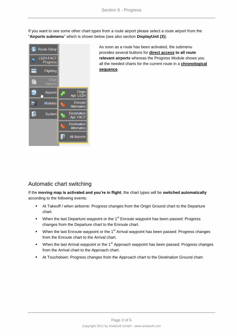
Section 6 - Progress
Page 3 of 6
Copyright 2011 by AivlaSoft GmbH - www.aivlasoft.com
If you want to see some other chart types from a route airport please select a route airport from the
"Airports submenu" which is shown below (see also section DisplayUnit (3)).
As soon as a route has been activated, the submenu
provides several buttons for direct access to all route
relevant airports whereas the Progress Module shows you
all the needed charts for the current route in a chronological
sequence.
Automatic chart switching
If the moving map is activated and you‟re in flight, the chart types will be switched automatically
according to the following events:
At Takeoff / when airborne: Progress changes from the Origin Ground chart to the Departure
chart.
When the last Departure waypoint or the 1st Enroute waypoint has been passed: Progress
changes from the Departure chart to the Enroute chart.
When the last Enroute waypoint or the 1st Arrival waypoint has been passed: Progress changes
from the Enroute chart to the Arrival chart.
When the last Arrival waypoint or the 1st Approach waypoint has been passed: Progress changes
from the Arrival chart to the Approach chart.
At Touchdown: Progress changes from the Approach chart to the Destination Ground chart.
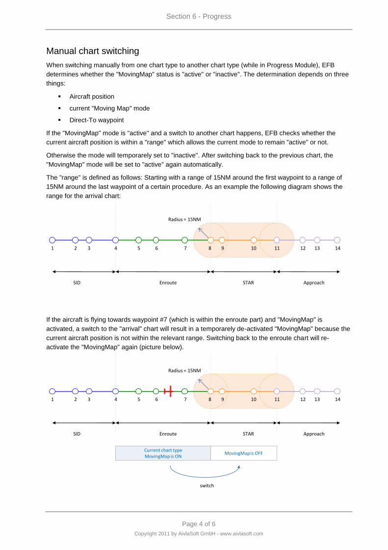
Section 6 - Progress
Page 4 of 6
Copyright 2011 by AivlaSoft GmbH - www.aivlasoft.com
Manual chart switching
When switching manually from one chart type to another chart type (while in Progress Module), EFB
determines whether the "MovingMap" status is "active" or "inactive". The determination depends on three
things:
Aircraft position
current "Moving Map" mode
Direct-To waypoint
If the "MovingMap" mode is "active" and a switch to another chart happens, EFB checks whether the
current aircraft position is within a "range" which allows the current mode to remain "active" or not.
Otherwise the mode will temporarely set to "inactive". After switching back to the previous chart, the
"MovingMap" mode will be set to "active" again automatically.
The "range" is defined as follows: Starting with a range of 15NM around the first waypoint to a range of
15NM around the last waypoint of a certain procedure. As an example the following diagram shows the
range for the arrival chart:
Radius = 15NM
SID STAREnroute Approach
1 2 3 4 5 6 7 8 9 10 11 12 13 14
Activation Area SID
Activation Area ENROUTE
Activation Area STAR
Activation Area APPROACH
If the aircraft is flying towards waypoint #7 (which is within the enroute part) and "MovingMap" is
activated, a switch to the "arrival" chart will result in a temporarely de-activated "MovingMap" because the
current aircraft position is not within the relevant range. Switching back to the enroute chart will re-
activate the "MovingMap" again (picture below).
Radius = 15NM
SID STAREnroute Approach
1 2 3 4 5 6 7 8 9 10 11 12 13 14
Current chart typeMovingMap is ON
Activation Area ENROUTE
Activation Area STAR
Activation Area APPROACH
MovingMap is OFF
switch
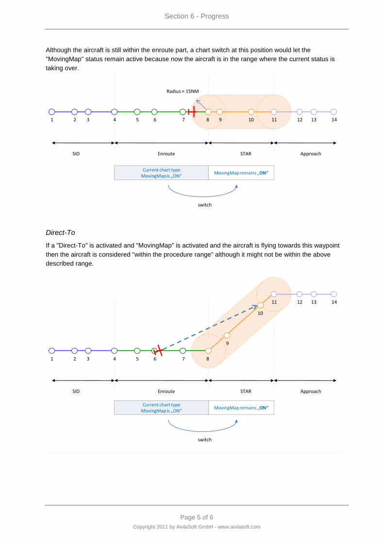
Section 6 - Progress
Page 5 of 6
Copyright 2011 by AivlaSoft GmbH - www.aivlasoft.com
Although the aircraft is still within the enroute part, a chart switch at this position would let the
"MovingMap" status remain active because now the aircraft is in the range where the current status is
taking over.
Radius = 15NM
SID STAREnroute Approach
1 2 3 4 5 6 7 8 9 10 11 12 13 14
Current chart typeMovingMap is „ON“
Activation Area ENROUTE
Activation Area STAR
Activation Area APPROACH
MovingMap remains „ON“
switch
Direct-To
If a "Direct-To" is activated and "MovingMap" is activated and the aircraft is flying towards this waypoint
then the aircraft is considered "within the procedure range" although it might not be within the above
described range.
Radius = 15NM
SID STAREnroute Approach
1 2 3 4 5 6 7 8
9
10
11 12 13 14
Current chart typeMovingMap is „ON“
MovingMap remains „ON“
switch
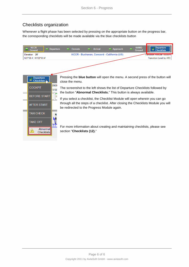
Section 6 - Progress
Page 6 of 6
Copyright 2011 by AivlaSoft GmbH - www.aivlasoft.com
Checklists organization
Whenever a flight phase has been selected by pressing on the appropriate button on the progress bar,
the corresponding checklists will be made available via the blue checklists button
Pressing the blue button will open the menu. A second press of the button will
close the menu.
The screenshot to the left shows the list of Departure Checklists followed by
the button "Abnormal Checklists." This button is always available.
If you select a checklist, the Checklist Module will open wherein you can go
through all the steps of a checklist. After closing the Checklists Module you will
be redirected to the Progress Module again.
For more information about creating and maintaining checklists, please see
section "Checklists (12)."

Page 1 of 38
Copyright 2011 by AivlaSoft GmbH - www.aivlasoft.com
Section 7 - Charts
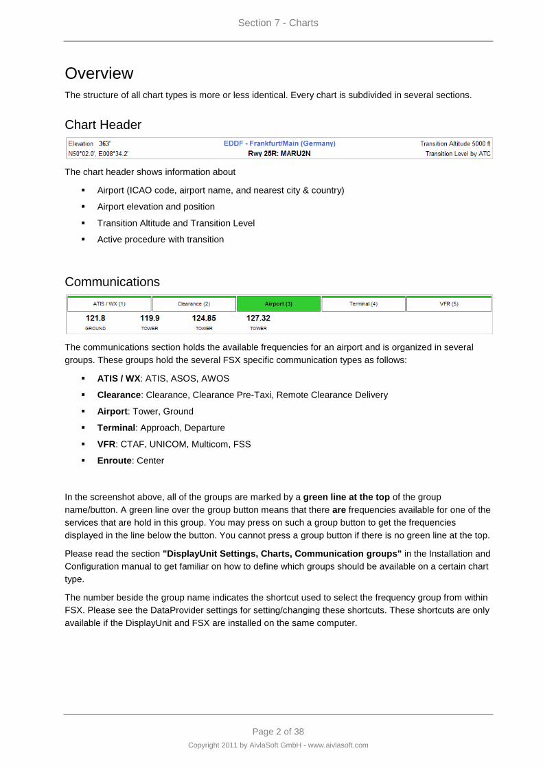
Section 7 - Charts
Page 2 of 38
Copyright 2011 by AivlaSoft GmbH - www.aivlasoft.com
Overview
The structure of all chart types is more or less identical. Every chart is subdivided in several sections.
Chart Header
The chart header shows information about
Airport (ICAO code, airport name, and nearest city & country)
Airport elevation and position
Transition Altitude and Transition Level
Active procedure with transition
Communications
The communications section holds the available frequencies for an airport and is organized in several
groups. These groups hold the several FSX specific communication types as follows:
ATIS / WX: ATIS, ASOS, AWOS
Clearance: Clearance, Clearance Pre-Taxi, Remote Clearance Delivery
Airport: Tower, Ground
Terminal: Approach, Departure
VFR: CTAF, UNICOM, Multicom, FSS
Enroute: Center
In the screenshot above, all of the groups are marked by a green line at the top of the group
name/button. A green line over the group button means that there are frequencies available for one of the
services that are hold in this group. You may press on such a group button to get the frequencies
displayed in the line below the button. You cannot press a group button if there is no green line at the top.
Please read the section "DisplayUnit Settings, Charts, Communication groups" in the Installation and
Configuration manual to get familiar on how to define which groups should be available on a certain chart
type.
The number beside the group name indicates the shortcut used to select the frequency group from within
FSX. Please see the DataProvider settings for setting/changing these shortcuts. These shortcuts are only
available if the DisplayUnit and FSX are installed on the same computer.
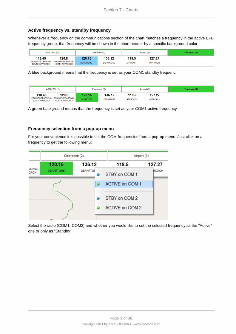
Section 7 - Charts
Page 3 of 38
Copyright 2011 by AivlaSoft GmbH - www.aivlasoft.com
Active frequency vs. standby frequency
Whenever a frequency on the communications section of the chart matches a frequency in the active EFB
frequency group, that frequency will be shown in the chart header by a specific background color.
A blue background means that the frequency is set as your COM1 standby frequenc
A green background means that the frequency is set as your COM1 active frequency
Frequency selection from a pop-up menu
For your convenience it is possible to set the COM frequencies from a pop-up menu. Just click on a
frequency to get the following menu:
Select the radio (COM1, COM2) and whether you would like to set the selected frequency as the "Active"
one or only as "Standby".
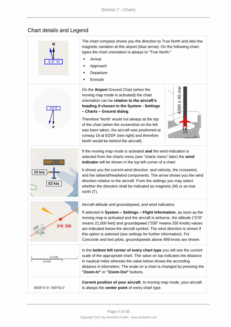
Section 7 - Charts
Page 4 of 38
Copyright 2011 by AivlaSoft GmbH - www.aivlasoft.com
Chart details and Legend
The chart compass shows you the direction to True North and also the
magnetic variation at this airport (blue arrow). On the following chart-
types the chart orientation is always to "True North:"
Arrival
Approach
Departure
Enroute
On the Airport Ground Chart (when the
moving map mode is activated) the chart
orientation can be relative to the aircraft‟s
heading if chosen in the System - Settings
– Charts – Ground dialog.
Therefore 'North' would not always at the top
of the chart (when the screenshot on the left
was been taken, the aircraft was positioned at
runway 18 at EDDF (see right) and therefore
North would be behind the aircraft).
If the moving map mode is activated and the wind indication is
selected from the charts menu (see "charts menu" later) the wind
indicator will be shown in the top left corner of a chart.
It shows you the current wind direction and velocity, the crosswind,
and the tailwind/headwind components. The arrow shows you the wind
direction relative to the aircraft. From the settings you may select
whether the direction shall be indicated as magnetic (M) or as true
north (T).
Aircraft altitude and groundspeed, and wind indicators
If selected in System – Settings – Flight Information, as soon as the
moving map is activated and the aircraft is airborne, the altitude (“210”
means 21,000 feet) and groundspeed (“330” means 330 knots) values
are indicated below the aircraft symbol. The wind direction is shown if
this option is selected (see settings for further information). For
Concorde and test pilots, groundspeeds above 999 knots are shown.
In the bottom left corner of every chart type you will see the current
scale of the appropriate chart. The value on top indicates the distance
in nautical miles whereas the value below shows the according
distance in kilometers. The scale on a chart is changed by pressing the
"Zoom-In" or "Zoom-Out" buttons.
Current position of your aircraft. In moving map mode, your aircraft
is always the center point of every chart type.
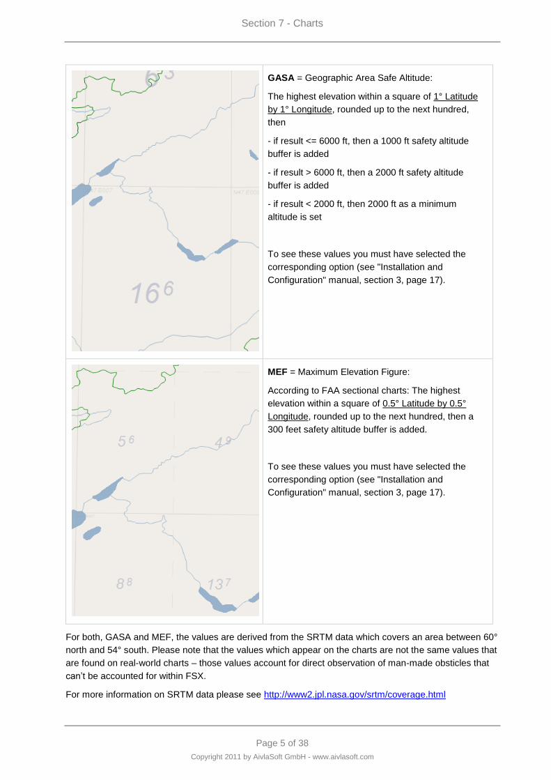
Section 7 - Charts
Page 5 of 38
Copyright 2011 by AivlaSoft GmbH - www.aivlasoft.com
GASA = Geographic Area Safe Altitude:
The highest elevation within a square of 1° Latitude
by 1° Longitude, rounded up to the next hundred,
then
- if result <= 6000 ft, then a 1000 ft safety altitude
buffer is added
- if result > 6000 ft, then a 2000 ft safety altitude
buffer is added
- if result < 2000 ft, then 2000 ft as a minimum
altitude is set
To see these values you must have selected the
corresponding option (see "Installation and
Configuration" manual, section 3, page 17).
MEF = Maximum Elevation Figure:
According to FAA sectional charts: The highest
elevation within a square of 0.5° Latitude by 0.5°
Longitude, rounded up to the next hundred, then a
300 feet safety altitude buffer is added.
To see these values you must have selected the
corresponding option (see "Installation and
Configuration" manual, section 3, page 17).
For both, GASA and MEF, the values are derived from the SRTM data which covers an area between 60°
north and 54° south. Please note that the values which appear on the charts are not the same values that
are found on real-world charts – those values account for direct observation of man-made obsticles that
can‟t be accounted for within FSX.
For more information on SRTM data please see http://www2.jpl.nasa.gov/srtm/coverage.html
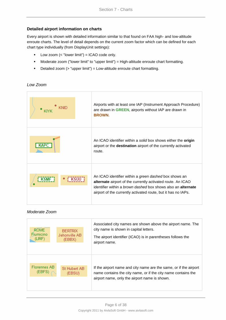
Section 7 - Charts
Page 6 of 38
Copyright 2011 by AivlaSoft GmbH - www.aivlasoft.com
Detailed airport information on charts
Every airport is shown with detailed information similar to that found on FAA high- and low-altitude
enroute charts. The level of detail depends on the current zoom factor which can be defined for each
chart type individually (from DisplayUnit settings):
Low zoom (< "lower limit") = ICAO code only.
Moderate zoom ("lower limit" to "upper limit") = High-altitude enroute chart formatting.
Detailed zoom (> "upper limit") = Low-altitude enroute chart formatting.
Low Zoom
Airports with at least one IAP (Instrument Approach Procedure)
are drawn in GREEN, airports without IAP are drawn in
BROWN.
An ICAO identifier within a solid box shows either the origin
airport or the destination airport of the currently activated
route.
An ICAO identifier within a green dashed box shows an
alternate airport of the currently activated route. An ICAO
identifier within a brown dashed box shows also an alternate
airport of the currently activated route, but it has no IAPs.
Moderate Zoom
Associated city names are shown above the airport name. The
city name is shown in capital letters.
The airport identifier (ICAO) is in parentheses follows the
airport name.
If the airport name and city name are the same, or if the airport
name contains the city name, or if the city name contains the
airport name, only the airport name is shown.
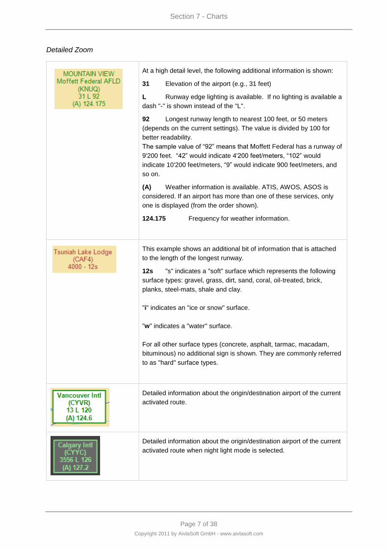
Section 7 - Charts
Page 7 of 38
Copyright 2011 by AivlaSoft GmbH - www.aivlasoft.com
Detailed Zoom
At a high detail level, the following additional information is shown:
31 Elevation of the airport (e.g., 31 feet)
L Runway edge lighting is available. If no lighting is available a
dash "-" is shown instead of the "L".
92 Longest runway length to nearest 100 feet, or 50 meters
(depends on the current settings). The value is divided by 100 for
better readability.
The sample value of “92” means that Moffett Federal has a runway of
9'200 feet. “42” would indicate 4'200 feet/meters, “102” would
indicate 10'200 feet/meters, “9” would indicate 900 feet/meters, and
so on.
(A) Weather information is available. ATIS, AWOS, ASOS is
considered. If an airport has more than one of these services, only
one is displayed (from the order shown).
124.175 Frequency for weather information.
This example shows an additional bit of information that is attached
to the length of the longest runway.
12s "s" indicates a "soft" surface which represents the following
surface types: gravel, grass, dirt, sand, coral, oil-treated, brick,
planks, steel-mats, shale and clay.
"i" indicates an "ice or snow" surface.
"w" indicates a "water" surface.
For all other surface types (concrete, asphalt, tarmac, macadam,
bituminous) no additional sign is shown. They are commonly referred
to as "hard" surface types.
Detailed information about the origin/destination airport of the current
activated route.
Detailed information about the origin/destination airport of the current
activated route when night light mode is selected.
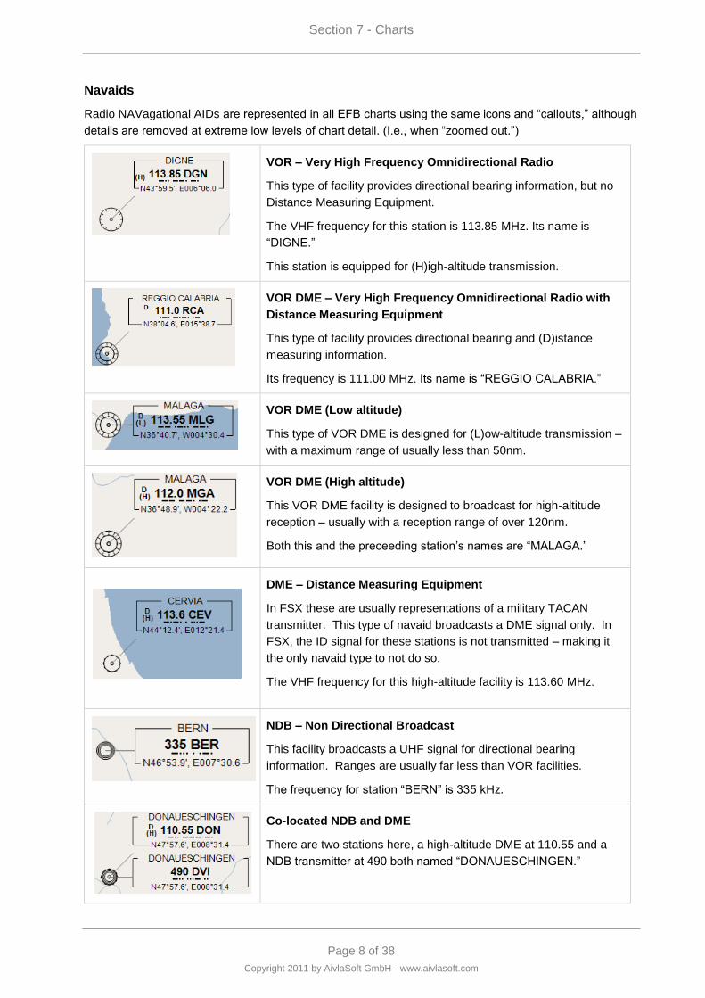
Section 7 - Charts
Page 8 of 38
Copyright 2011 by AivlaSoft GmbH - www.aivlasoft.com
Navaids
Radio NAVagational AIDs are represented in all EFB charts using the same icons and “callouts,” although
details are removed at extreme low levels of chart detail. (I.e., when “zoomed out.”)
VOR – Very High Frequency Omnidirectional Radio
This type of facility provides directional bearing information, but no
Distance Measuring Equipment.
The VHF frequency for this station is 113.85 MHz. Its name is
“DIGNE.”
This station is equipped for (H)igh-altitude transmission.
VOR DME – Very High Frequency Omnidirectional Radio with
Distance Measuring Equipment
This type of facility provides directional bearing and (D)istance
measuring information.
Its frequency is 111.00 MHz. Its name is “REGGIO CALABRIA.”
VOR DME (Low altitude)
This type of VOR DME is designed for (L)ow-altitude transmission –
with a maximum range of usually less than 50nm.
VOR DME (High altitude)
This VOR DME facility is designed to broadcast for high-altitude
reception – usually with a reception range of over 120nm.
Both this and the preceeding station‟s names are “MALAGA.”
DME – Distance Measuring Equipment
In FSX these are usually representations of a military TACAN
transmitter. This type of navaid broadcasts a DME signal only. In
FSX, the ID signal for these stations is not transmitted – making it
the only navaid type to not do so.
The VHF frequency for this high-altitude facility is 113.60 MHz.
NDB – Non Directional Broadcast
This facility broadcasts a UHF signal for directional bearing
information. Ranges are usually far less than VOR facilities.
The frequency for station “BERN” is 335 kHz.
Co-located NDB and DME
There are two stations here, a high-altitude DME at 110.55 and a
NDB transmitter at 490 both named “DONAUESCHINGEN.”
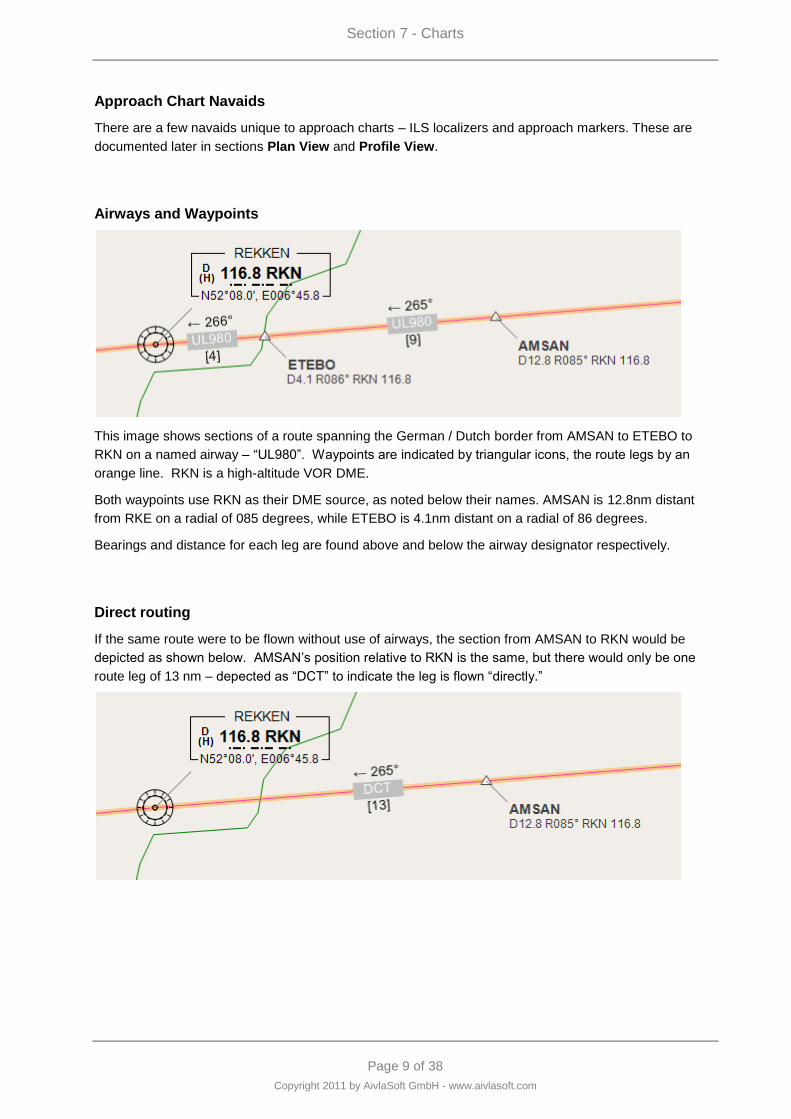
Section 7 - Charts
Page 9 of 38
Copyright 2011 by AivlaSoft GmbH - www.aivlasoft.com
Approach Chart Navaids
There are a few navaids unique to approach charts – ILS localizers and approach markers. These are
documented later in sections Plan View and Profile View.
Airways and Waypoints
This image shows sections of a route spanning the German / Dutch border from AMSAN to ETEBO to
RKN on a named airway – “UL980”. Waypoints are indicated by triangular icons, the route legs by an
orange line. RKN is a high-altitude VOR DME.
Both waypoints use RKN as their DME source, as noted below their names. AMSAN is 12.8nm distant
from RKE on a radial of 085 degrees, while ETEBO is 4.1nm distant on a radial of 86 degrees.
Bearings and distance for each leg are found above and below the airway designator respectively.
Direct routing
If the same route were to be flown without use of airways, the section from AMSAN to RKN would be
depicted as shown below. AMSAN‟s position relative to RKN is the same, but there would only be one
route leg of 13 nm – depected as “DCT” to indicate the leg is flown “directly.”
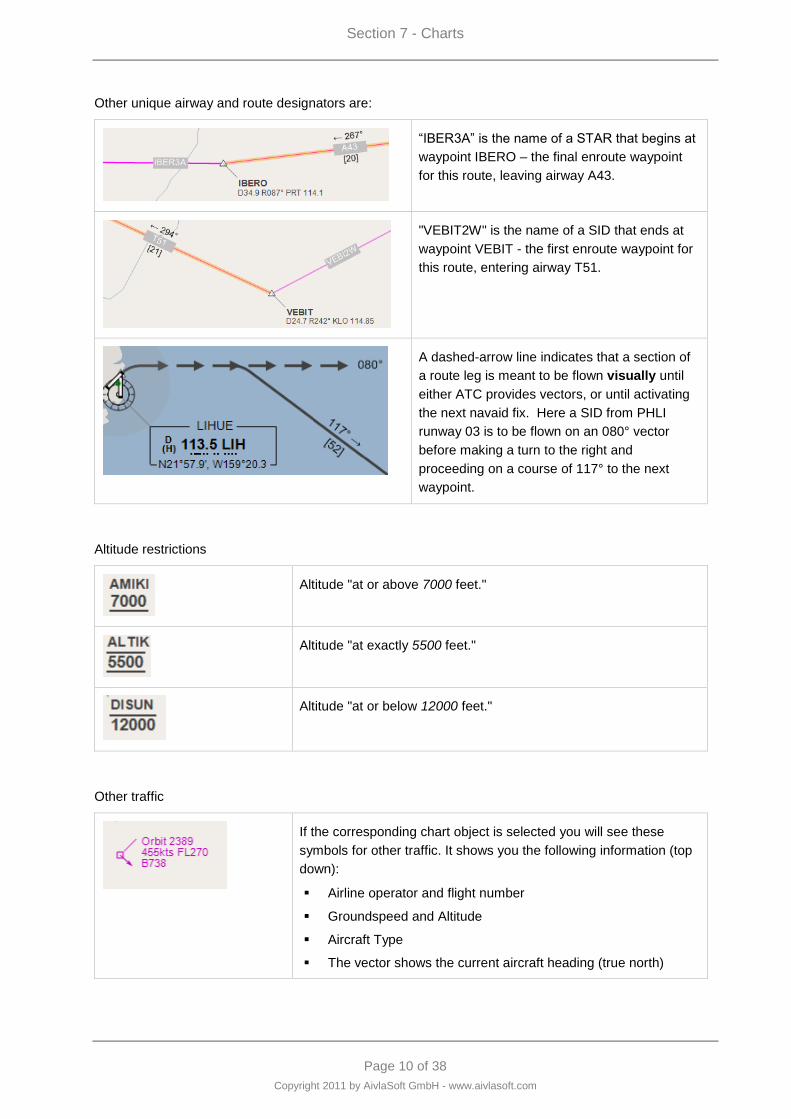
Section 7 - Charts
Page 10 of 38
Copyright 2011 by AivlaSoft GmbH - www.aivlasoft.com
Other unique airway and route designators are:
“IBER3A” is the name of a STAR that begins at
waypoint IBERO – the final enroute waypoint
for this route, leaving airway A43.
"VEBIT2W" is the name of a SID that ends at
waypoint VEBIT - the first enroute waypoint for
this route, entering airway T51.
A dashed-arrow line indicates that a section of
a route leg is meant to be flown visually until
either ATC provides vectors, or until activating
the next navaid fix. Here a SID from PHLI
runway 03 is to be flown on an 080° vector
before making a turn to the right and
proceeding on a course of 117° to the next
waypoint.
Altitude restrictions
Altitude "at or above 7000 feet."
Altitude "at exactly 5500 feet."
Altitude "at or below 12000 feet."
Other traffic
If the corresponding chart object is selected you will see these
symbols for other traffic. It shows you the following information (top
down):
Airline operator and flight number
Groundspeed and Altitude
Aircraft Type
The vector shows the current aircraft heading (true north)
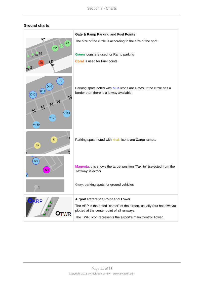
Section 7 - Charts
Page 11 of 38
Copyright 2011 by AivlaSoft GmbH - www.aivlasoft.com
Ground charts
Gate & Ramp Parking and Fuel Points
The size of the circle is according to the size of the spot.
Green icons are used for Ramp parking
Coral is used for Fuel points.
Parking spots noted with blue icons are Gates. If the circle has a
border then there is a jetway available.
Parking spots noted with khaki icons are Cargo ramps.
Magenta: this shows the target position "Taxi to" (selected from the
TaxiwaySelector)
Gray: parking spots for ground vehicles
Airport Reference Point and Tower
The ARP is the noted “center” of the airport, usually (but not always)
plotted at the center point of all runways.
The TWR icon represents the airport‟s main Control Tower.

Section 7 - Charts
Page 12 of 38
Copyright 2011 by AivlaSoft GmbH - www.aivlasoft.com
Taxiways
Taxiways are noted with alphanumeric indicators on each segment.
Runway Dimensions
Runway length and width values are listed parallel to their path.
Runway Designator and Bearing
Designators and bearings are listed at each end of a runway.
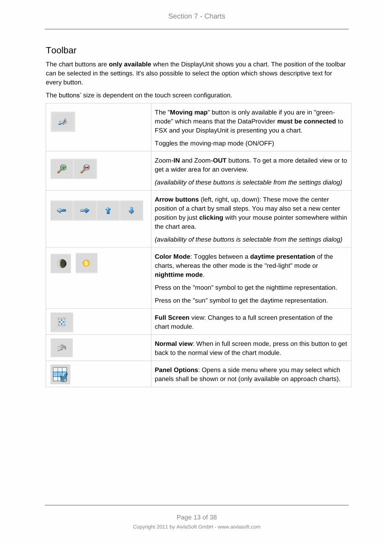
Section 7 - Charts
Page 13 of 38
Copyright 2011 by AivlaSoft GmbH - www.aivlasoft.com
Toolbar
The chart buttons are only available when the DisplayUnit shows you a chart. The position of the toolbar
can be selected in the settings. It's also possible to select the option which shows descriptive text for
every button.
The buttons‟ size is dependent on the touch screen configuration.
The "Moving map" button is only available if you are in "green-
mode" which means that the DataProvider must be connected to
FSX and your DisplayUnit is presenting you a chart.
Toggles the moving-map mode (ON/OFF)
Zoom-IN and Zoom-OUT buttons. To get a more detailed view or to
get a wider area for an overview.
(availability of these buttons is selectable from the settings dialog)
Arrow buttons (left, right, up, down): These move the center
position of a chart by small steps. You may also set a new center
position by just clicking with your mouse pointer somewhere within
the chart area.
(availability of these buttons is selectable from the settings dialog)
Color Mode: Toggles between a daytime presentation of the
charts, whereas the other mode is the "red-light" mode or
nighttime mode.
Press on the "moon" symbol to get the nighttime representation.
Press on the "sun" symbol to get the daytime representation.
Full Screen view: Changes to a full screen presentation of the
chart module.
Normal view: When in full screen mode, press on this button to get
back to the normal view of the chart module.
Panel Options: Opens a side menu where you may select which
panels shall be shown or not (only available on approach charts).
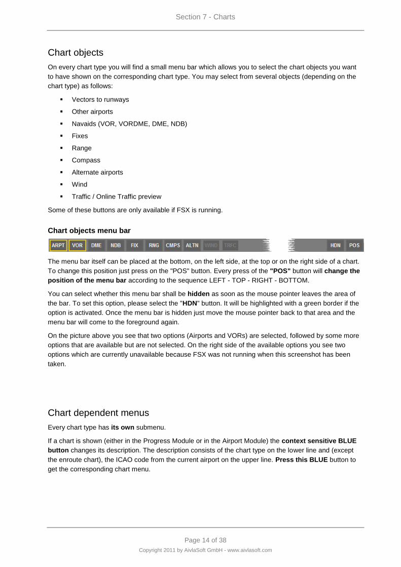
Section 7 - Charts
Page 14 of 38
Copyright 2011 by AivlaSoft GmbH - www.aivlasoft.com
Chart objects
On every chart type you will find a small menu bar which allows you to select the chart objects you want
to have shown on the corresponding chart type. You may select from several objects (depending on the
chart type) as follows:
Vectors to runways
Other airports
Navaids (VOR, VORDME, DME, NDB)
Fixes
Range
Compass
Alternate airports
Wind
Traffic / Online Traffic preview
Some of these buttons are only available if FSX is running.
Chart objects menu bar
The menu bar itself can be placed at the bottom, on the left side, at the top or on the right side of a chart.
To change this position just press on the "POS" button. Every press of the "POS" button will change the
position of the menu bar according to the sequence LEFT - TOP - RIGHT - BOTTOM.
You can select whether this menu bar shall be hidden as soon as the mouse pointer leaves the area of
the bar. To set this option, please select the "HDN" button. It will be highlighted with a green border if the
option is activated. Once the menu bar is hidden just move the mouse pointer back to that area and the
menu bar will come to the foreground again.
On the picture above you see that two options (Airports and VORs) are selected, followed by some more
options that are available but are not selected. On the right side of the available options you see two
options which are currently unavailable because FSX was not running when this screenshot has been
taken.
Chart dependent menus
Every chart type has its own submenu.
If a chart is shown (either in the Progress Module or in the Airport Module) the context sensitive BLUE
button changes its description. The description consists of the chart type on the lower line and (except
the enroute chart), the ICAO code from the current airport on the upper line. Press this BLUE button to
get the corresponding chart menu.
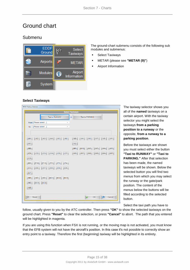
Section 7 - Charts
Page 15 of 38
Copyright 2011 by AivlaSoft GmbH - www.aivlasoft.com
Ground chart
Submenu
The ground-chart submenu consists of the following sub modules and submenus:
Select Taxiways
METAR (please see "METAR (9)")
Airport Information
Select Taxiways
The taxiway selector shows you
all of the named taxiways on a
certain airport. With the taxiway
selector you might select the
taxiways from a parking
position to a runway or the
opposite, from a runway to a
parking position.
Before the taxiways are shown
you must select either the button
"Taxi to RUNWAY" or "Taxi to
PARKING." After that selection
has been made, the named
taxiways will be shown. Below the
selected button you will find two
menus from which you may select
the runway or the gate/park
position. The content of the
menus below the buttons will be
filled according to the selected
button.
Select the taxi path you have to
follow, usually given to you by the ATC controller. Then press "OK" to show the selected taxiways on the
ground chart. Press "Reset" to clear the selection, or press "Cancel" to abort. The path that you entered
will be highlighted in magenta.
If you are using this function when FSX is not running, or the moving map is not activated, you must know
that the EFB system will not have the aircraft‟s position. In this case it's not possible to correctly show an
entry point to a taxiway. Therefore the first (beginning) taxiway will be highlighted in its entirety.
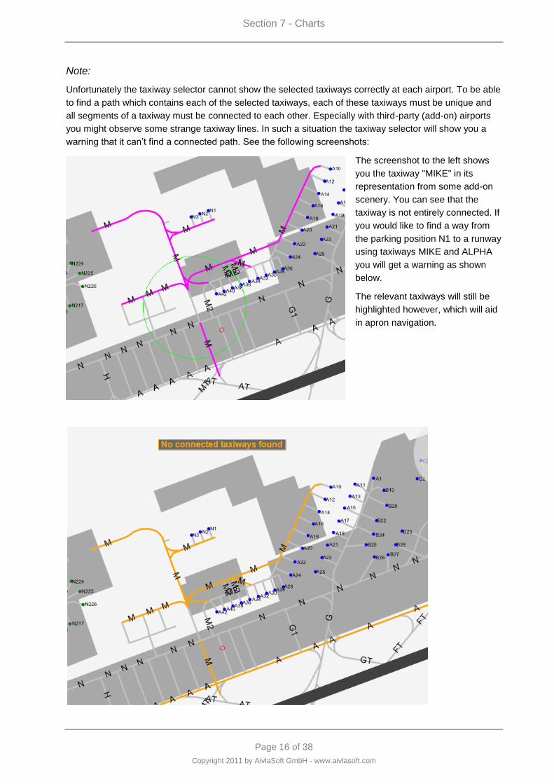
Section 7 - Charts
Page 16 of 38
Copyright 2011 by AivlaSoft GmbH - www.aivlasoft.com
Note:
Unfortunately the taxiway selector cannot show the selected taxiways correctly at each airport. To be able
to find a path which contains each of the selected taxiways, each of these taxiways must be unique and
all segments of a taxiway must be connected to each other. Especially with third-party (add-on) airports
you might observe some strange taxiway lines. In such a situation the taxiway selector will show you a
warning that it can‟t find a connected path. See the following screenshots:
The screenshot to the left shows
you the taxiway "MIKE" in its
representation from some add-on
scenery. You can see that the
taxiway is not entirely connected. If
you would like to find a way from
the parking position N1 to a runway
using taxiways MIKE and ALPHA
you will get a warning as shown
below.
The relevant taxiways will still be
highlighted however, which will aid
in apron navigation.
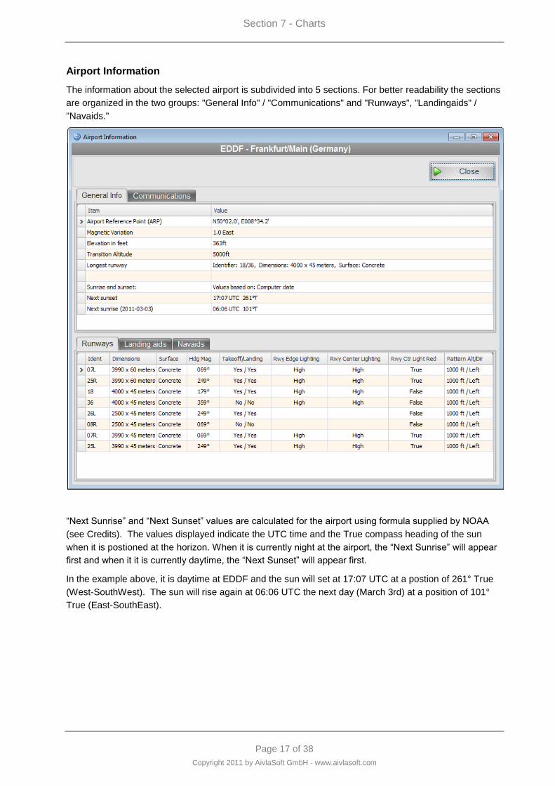
Section 7 - Charts
Page 17 of 38
Copyright 2011 by AivlaSoft GmbH - www.aivlasoft.com
Airport Information
The information about the selected airport is subdivided into 5 sections. For better readability the sections
are organized in the two groups: "General Info" / "Communications" and "Runways", "Landingaids" /
"Navaids."
“Next Sunrise” and “Next Sunset” values are calculated for the airport using formula supplied by NOAA
(see Credits). The values displayed indicate the UTC time and the True compass heading of the sun
when it is postioned at the horizon. When it is currently night at the airport, the “Next Sunrise” will appear
first and when it it is currently daytime, the “Next Sunset” will appear first.
In the example above, it is daytime at EDDF and the sun will set at 17:07 UTC at a postion of 261° True
(West-SouthWest). The sun will rise again at 06:06 UTC the next day (March 3rd) at a position of 101°
True (East-SouthEast).
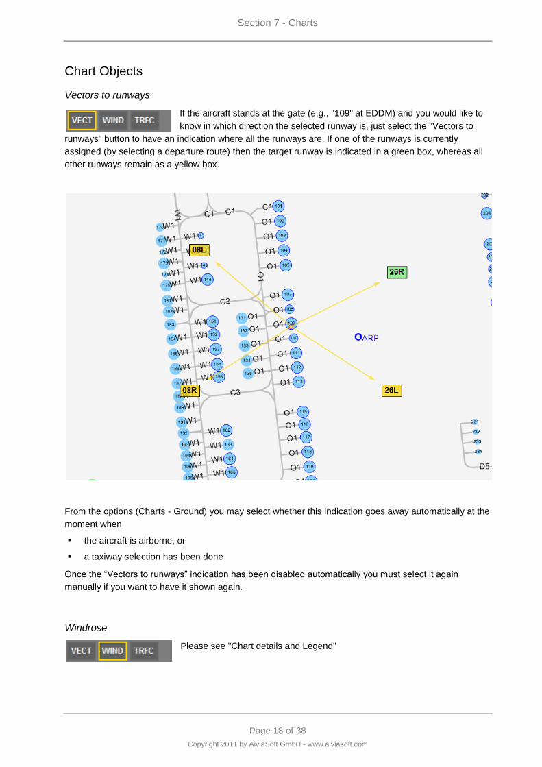
Section 7 - Charts
Page 18 of 38
Copyright 2011 by AivlaSoft GmbH - www.aivlasoft.com
Chart Objects
Vectors to runways
If the aircraft stands at the gate (e.g., "109" at EDDM) and you would like to
know in which direction the selected runway is, just select the "Vectors to
runways" button to have an indication where all the runways are. If one of the runways is currently
assigned (by selecting a departure route) then the target runway is indicated in a green box, whereas all
other runways remain as a yellow box.
From the options (Charts - Ground) you may select whether this indication goes away automatically at the
moment when
the aircraft is airborne, or
a taxiway selection has been done
Once the “Vectors to runways” indication has been disabled automatically you must select it again
manually if you want to have it shown again.
Windrose
Please see "Chart details and Legend"
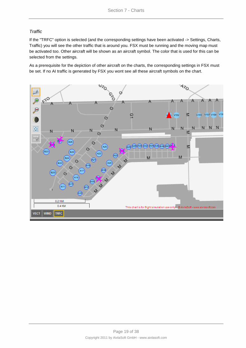
Section 7 - Charts
Page 19 of 38
Copyright 2011 by AivlaSoft GmbH - www.aivlasoft.com
Traffic
If the "TRFC" option is selected (and the corresponding settings have been activated -> Settings, Charts,
Traffic) you will see the other traffic that is around you. FSX must be running and the moving map must
be activated too. Other aircraft will be shown as an aircraft symbol. The color that is used for this can be
selected from the settings.
As a prerequisite for the depiction of other aircraft on the charts, the corresponding settings in FSX must
be set. If no AI traffic is generated by FSX you wont see all these aircraft symbols on the chart.
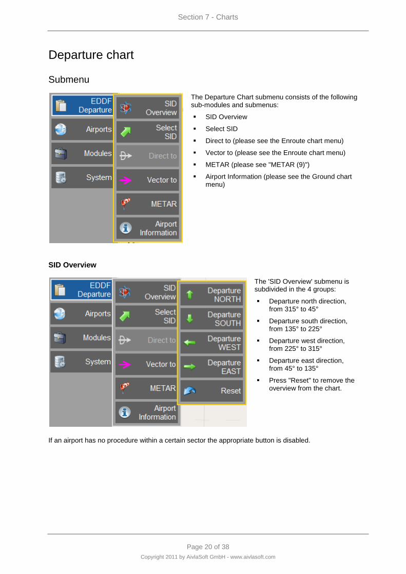
Section 7 - Charts
Page 20 of 38
Copyright 2011 by AivlaSoft GmbH - www.aivlasoft.com
Departure chart
Submenu
The Departure Chart submenu consists of the following sub-modules and submenus:
SID Overview
Select SID
Direct to (please see the Enroute chart menu)
Vector to (please see the Enroute chart menu)
METAR (please see "METAR (9)")
Airport Information (please see the Ground chart menu)
SID Overview
The 'SID Overview' submenu is subdivided in the 4 groups:
Departure north direction, from 315° to 45°
Departure south direction, from 135° to 225°
Departure west direction, from 225° to 315°
Departure east direction, from 45° to 135°
Press "Reset" to remove the overview from the chart.
If an airport has no procedure within a certain sector the appropriate button is disabled.
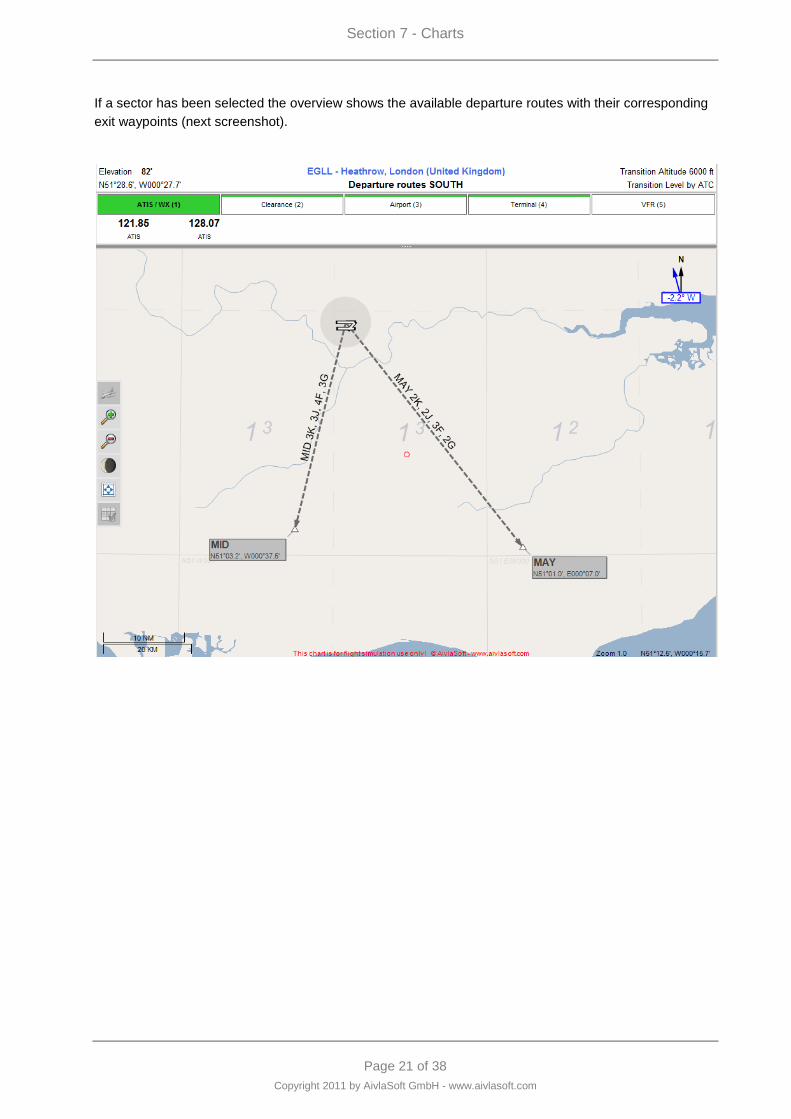
Section 7 - Charts
Page 21 of 38
Copyright 2011 by AivlaSoft GmbH - www.aivlasoft.com
If a sector has been selected the overview shows the available departure routes with their corresponding
exit waypoints (next screenshot).
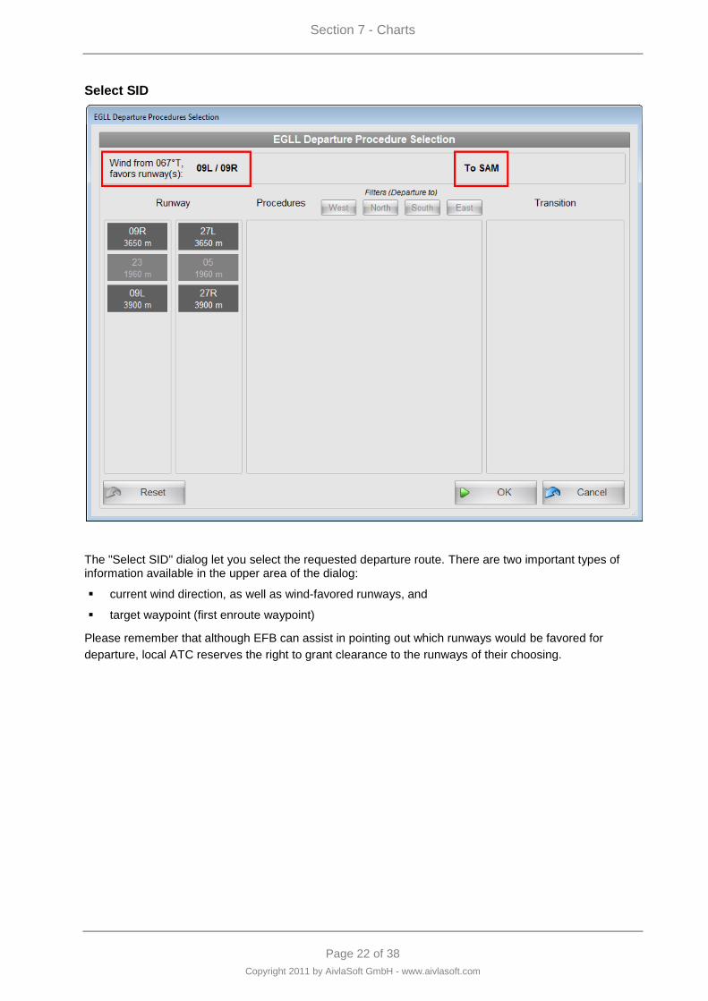
Section 7 - Charts
Page 22 of 38
Copyright 2011 by AivlaSoft GmbH - www.aivlasoft.com
Select SID
The "Select SID" dialog let you select the requested departure route. There are two important types of information available in the upper area of the dialog:
current wind direction, as well as wind-favored runways, and
target waypoint (first enroute waypoint)
Please remember that although EFB can assist in pointing out which runways would be favored for
departure, local ATC reserves the right to grant clearance to the runways of their choosing.
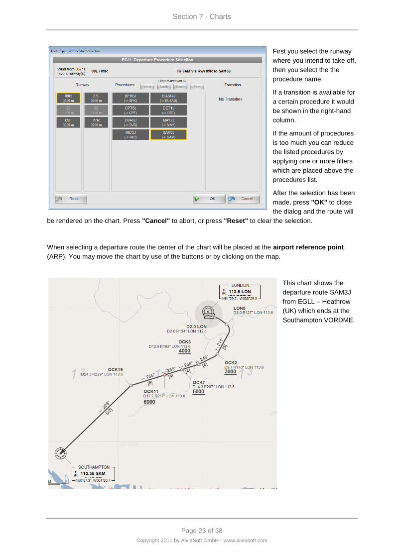
Section 7 - Charts
Page 23 of 38
Copyright 2011 by AivlaSoft GmbH - www.aivlasoft.com
First you select the runway
where you intend to take off,
then you select the the
procedure name.
If a transition is available for
a certain procedure it would
be shown in the right-hand
column.
If the amount of procedures
is too much you can reduce
the listed procedures by
applying one or more filters
which are placed above the
procedures list.
After the selection has been
made, press "OK" to close
the dialog and the route will
be rendered on the chart. Press "Cancel" to abort, or press "Reset" to clear the selection.
When selecting a departure route the center of the chart will be placed at the airport reference point
(ARP). You may move the chart by use of the buttons or by clicking on the map.
This chart shows the
departure route SAM3J
from EGLL – Heathrow
(UK) which ends at the
Southampton VORDME.
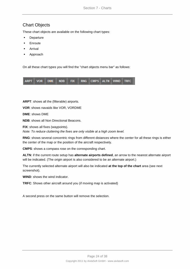
Section 7 - Charts
Page 24 of 38
Copyright 2011 by AivlaSoft GmbH - www.aivlasoft.com
Chart Objects
These chart objects are available on the following chart types:
Departure
Enroute
Arrival
Approach
On all these chart types you will find the "chart objects menu bar" as follows:
ARPT: shows all the (filterable) airports.
VOR: shows navaids like VOR, VORDME
DME: shows DME
NDB: shows all Non Directional Beacons.
FIX: shows all fixes (waypoints).
Note: To reduce cluttering the fixes are only visible at a high zoom level.
RNG: shows several concentric rings from different distances where the center for all these rings is either
the center of the map or the position of the aircraft respectively.
CMPS: shows a compass rose on the corresponding chart.
ALTN: if the current route setup has alternate airports defined, an arrow to the nearest alternate airport
will be indicated. (The origin airport is also considered to be an alternate airport.)
The currently selected alternate airport will also be indicated at the top of the chart area (see next
screenshot).
WIND: shows the wind indicator.
TRFC: Shows other aircraft around you (if moving map is activated)
A second press on the same button will remove the selection.
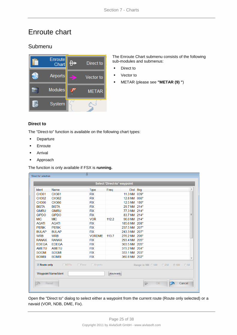
Section 7 - Charts
Page 25 of 38
Copyright 2011 by AivlaSoft GmbH - www.aivlasoft.com
Enroute chart
Submenu
The Enroute Chart submenu consists of the following sub-modules and submenus:
Direct to
Vector to
METAR (please see "METAR (9) ")
Direct to
The "Direct-to" function is available on the following chart types:
Departure
Enroute
Arrival
Approach
The function is only available if FSX is running.
Open the "Direct to" dialog to select either a waypoint from the current route (Route only selected) or a
navaid (VOR, NDB, DME, Fix).
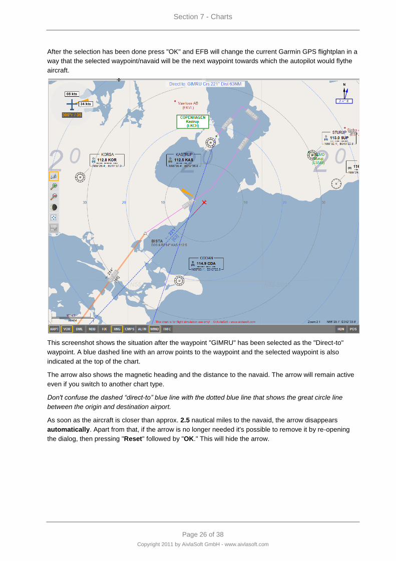
Section 7 - Charts
Page 26 of 38
Copyright 2011 by AivlaSoft GmbH - www.aivlasoft.com
After the selection has been done press "OK" and EFB will change the current Garmin GPS flightplan in a
way that the selected waypoint/navaid will be the next waypoint towards which the autopilot would flythe
aircraft.
This screenshot shows the situation after the waypoint "GIMRU" has been selected as the "Direct-to"
waypoint. A blue dashed line with an arrow points to the waypoint and the selected waypoint is also
indicated at the top of the chart.
The arrow also shows the magnetic heading and the distance to the navaid. The arrow will remain active
even if you switch to another chart type.
Don't confuse the dashed “direct-to” blue line with the dotted blue line that shows the great circle line
between the origin and destination airport.
As soon as the aircraft is closer than approx. 2.5 nautical miles to the navaid, the arrow disappears
automatically. Apart from that, if the arrow is no longer needed it's possible to remove it by re-opening
the dialog, then pressing "Reset" followed by "OK." This will hide the arrow.
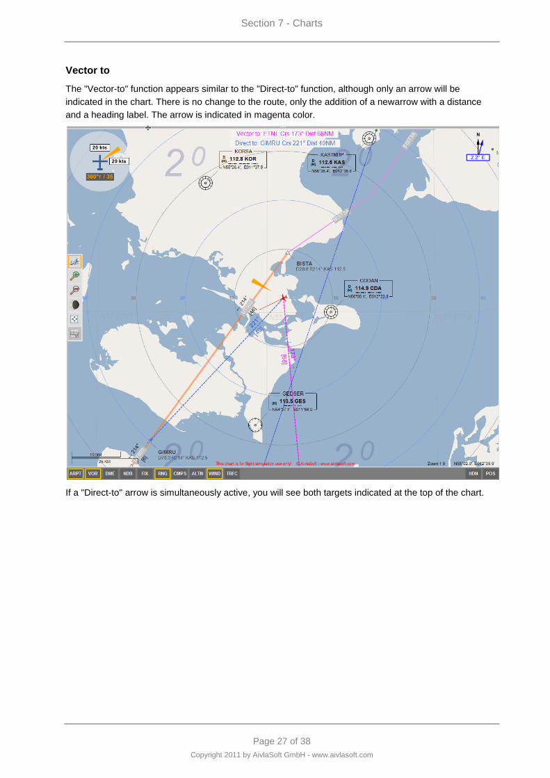
Section 7 - Charts
Page 27 of 38
Copyright 2011 by AivlaSoft GmbH - www.aivlasoft.com
Vector to
The "Vector-to" function appears similar to the "Direct-to" function, although only an arrow will be
indicated in the chart. There is no change to the route, only the addition of a newarrow with a distance
and a heading label. The arrow is indicated in magenta color.
If a "Direct-to" arrow is simultaneously active, you will see both targets indicated at the top of the chart.
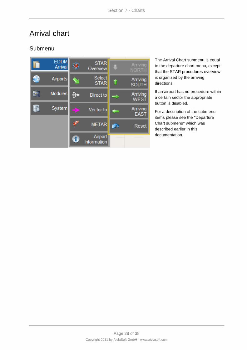
Section 7 - Charts
Page 28 of 38
Copyright 2011 by AivlaSoft GmbH - www.aivlasoft.com
Arrival chart
Submenu
The Arrival Chart submenu is equal
to the departure chart menu, except
that the STAR procedures overview
is organized by the arriving
directions.
If an airport has no procedure within
a certain sector the appropriate
button is disabled.
For a description of the submenu
items please see the "Departure
Chart submenu" which was
described earlier in this
documentation.
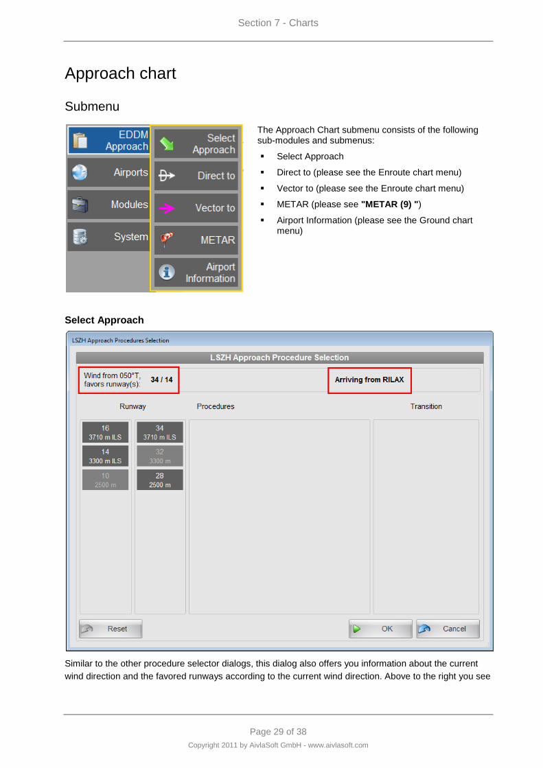
Section 7 - Charts
Page 29 of 38
Copyright 2011 by AivlaSoft GmbH - www.aivlasoft.com
Approach chart
Submenu
The Approach Chart submenu consists of the following sub-modules and submenus:
Select Approach
Direct to (please see the Enroute chart menu)
Vector to (please see the Enroute chart menu)
METAR (please see "METAR (9) ")
Airport Information (please see the Ground chart menu)
Select Approach
Similar to the other procedure selector dialogs, this dialog also offers you information about the current
wind direction and the favored runways according to the current wind direction. Above to the right you see
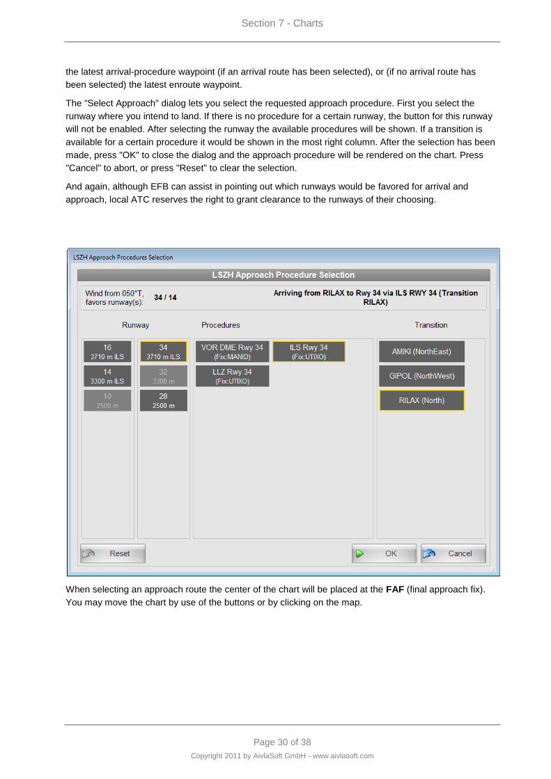
Section 7 - Charts
Page 30 of 38
Copyright 2011 by AivlaSoft GmbH - www.aivlasoft.com
the latest arrival-procedure waypoint (if an arrival route has been selected), or (if no arrival route has
been selected) the latest enroute waypoint.
The "Select Approach" dialog lets you select the requested approach procedure. First you select the
runway where you intend to land. If there is no procedure for a certain runway, the button for this runway
will not be enabled. After selecting the runway the available procedures will be shown. If a transition is
available for a certain procedure it would be shown in the most right column. After the selection has been
made, press "OK" to close the dialog and the approach procedure will be rendered on the chart. Press
"Cancel" to abort, or press "Reset" to clear the selection.
And again, although EFB can assist in pointing out which runways would be favored for arrival and
approach, local ATC reserves the right to grant clearance to the runways of their choosing.
When selecting an approach route the center of the chart will be placed at the FAF (final approach fix).
You may move the chart by use of the buttons or by clicking on the map.
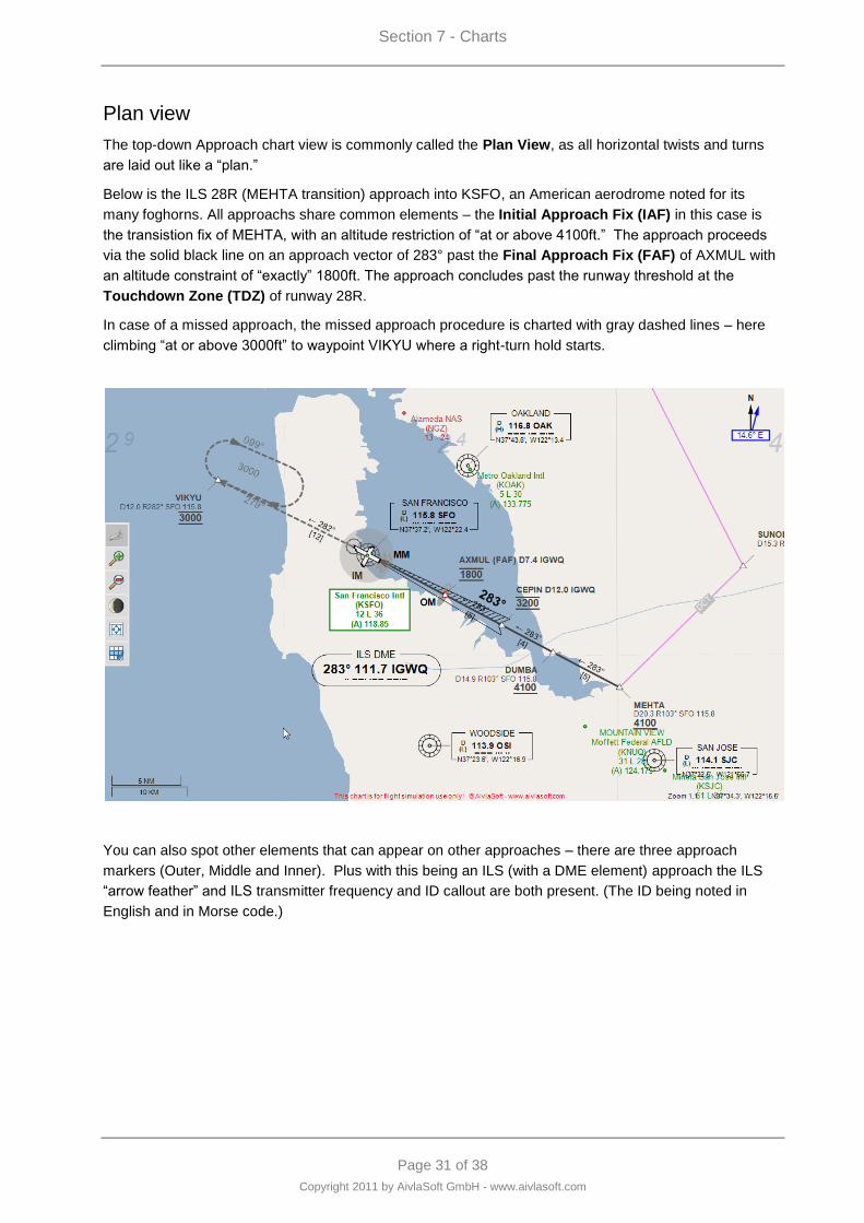
Section 7 - Charts
Page 31 of 38
Copyright 2011 by AivlaSoft GmbH - www.aivlasoft.com
Plan view
The top-down Approach chart view is commonly called the Plan View, as all horizontal twists and turns
are laid out like a “plan.”
Below is the ILS 28R (MEHTA transition) approach into KSFO, an American aerodrome noted for its
many foghorns. All approachs share common elements – the Initial Approach Fix (IAF) in this case is
the transistion fix of MEHTA, with an altitude restriction of “at or above 4100ft.” The approach proceeds
via the solid black line on an approach vector of 283° past the Final Approach Fix (FAF) of AXMUL with
an altitude constraint of “exactly” 1800ft. The approach concludes past the runway threshold at the
Touchdown Zone (TDZ) of runway 28R.
In case of a missed approach, the missed approach procedure is charted with gray dashed lines – here
climbing “at or above 3000ft” to waypoint VIKYU where a right-turn hold starts.
You can also spot other elements that can appear on other approaches – there are three approach
markers (Outer, Middle and Inner). Plus with this being an ILS (with a DME element) approach the ILS
“arrow feather” and ILS transmitter frequency and ID callout are both present. (The ID being noted in
English and in Morse code.)
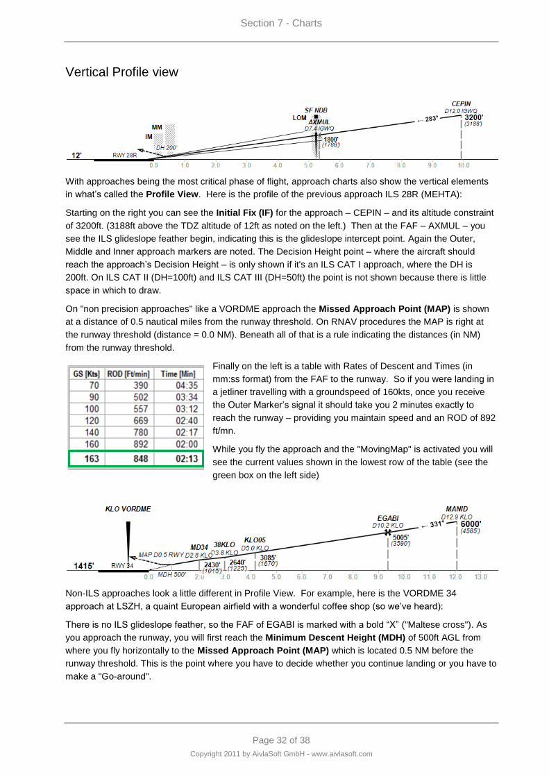
Section 7 - Charts
Page 32 of 38
Copyright 2011 by AivlaSoft GmbH - www.aivlasoft.com
Vertical Profile view
With approaches being the most critical phase of flight, approach charts also show the vertical elements
in what‟s called the Profile View. Here is the profile of the previous approach ILS 28R (MEHTA):
Starting on the right you can see the Initial Fix (IF) for the approach – CEPIN – and its altitude constraint
of 3200ft. (3188ft above the TDZ altitude of 12ft as noted on the left.) Then at the FAF – AXMUL – you
see the ILS glideslope feather begin, indicating this is the glideslope intercept point. Again the Outer,
Middle and Inner approach markers are noted. The Decision Height point – where the aircraft should
reach the approach‟s Decision Height – is only shown if it's an ILS CAT I approach, where the DH is
200ft. On ILS CAT II (DH=100ft) and ILS CAT III (DH=50ft) the point is not shown because there is little
space in which to draw.
On "non precision approaches" like a VORDME approach the Missed Approach Point (MAP) is shown
at a distance of 0.5 nautical miles from the runway threshold. On RNAV procedures the MAP is right at
the runway threshold (distance = 0.0 NM). Beneath all of that is a rule indicating the distances (in NM)
from the runway threshold.
Finally on the left is a table with Rates of Descent and Times (in
mm:ss format) from the FAF to the runway. So if you were landing in
a jetliner travelling with a groundspeed of 160kts, once you receive
the Outer Marker‟s signal it should take you 2 minutes exactly to
reach the runway – providing you maintain speed and an ROD of 892
ft/mn.
While you fly the approach and the "MovingMap" is activated you will
see the current values shown in the lowest row of the table (see the
green box on the left side)
Non-ILS approaches look a little different in Profile View. For example, here is the VORDME 34
approach at LSZH, a quaint European airfield with a wonderful coffee shop (so we‟ve heard):
There is no ILS glideslope feather, so the FAF of EGABI is marked with a bold “X” ("Maltese cross"). As
you approach the runway, you will first reach the Minimum Descent Height (MDH) of 500ft AGL from
where you fly horizontally to the Missed Approach Point (MAP) which is located 0.5 NM before the
runway threshold. This is the point where you have to decide whether you continue landing or you have to
make a "Go-around".
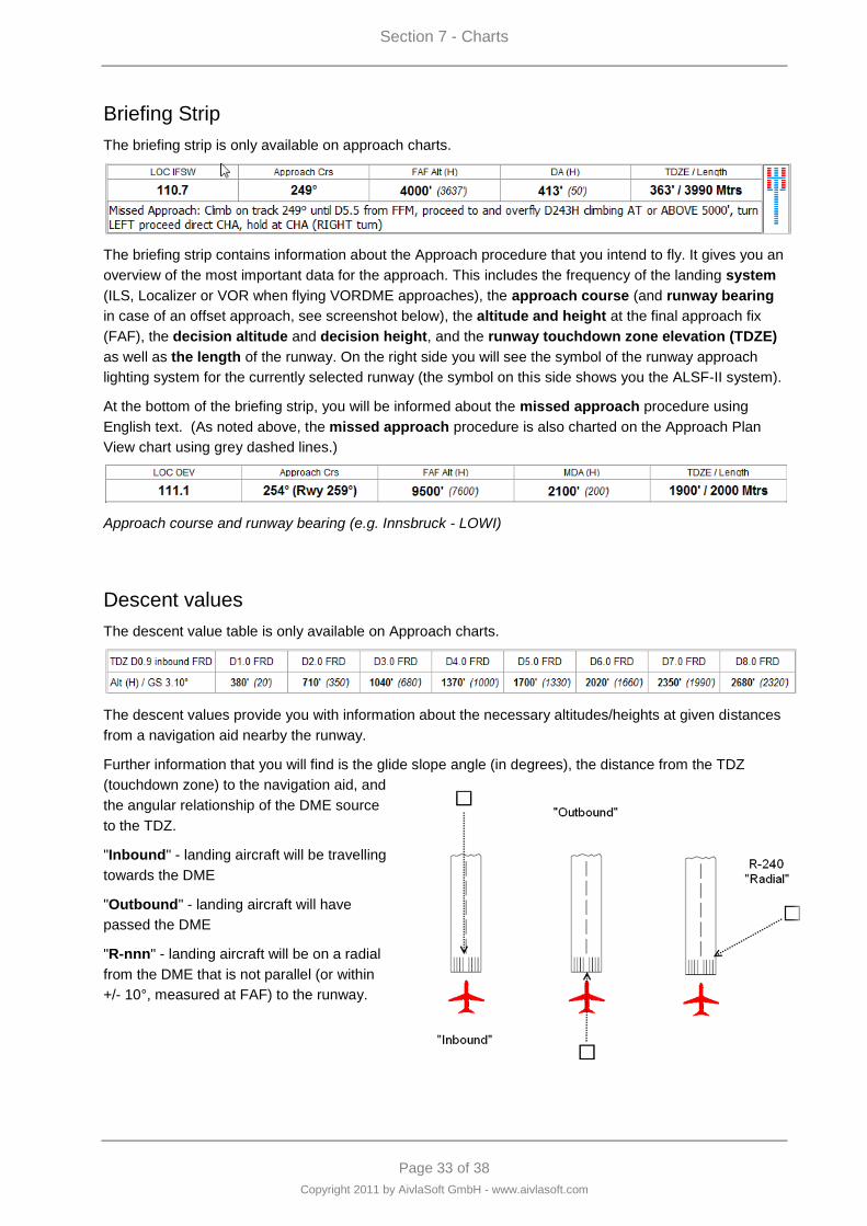
Section 7 - Charts
Page 33 of 38
Copyright 2011 by AivlaSoft GmbH - www.aivlasoft.com
Briefing Strip
The briefing strip is only available on approach charts.
The briefing strip contains information about the Approach procedure that you intend to fly. It gives you an
overview of the most important data for the approach. This includes the frequency of the landing system
(ILS, Localizer or VOR when flying VORDME approaches), the approach course (and runway bearing
in case of an offset approach, see screenshot below), the altitude and height at the final approach fix
(FAF), the decision altitude and decision height, and the runway touchdown zone elevation (TDZE)
as well as the length of the runway. On the right side you will see the symbol of the runway approach
lighting system for the currently selected runway (the symbol on this side shows you the ALSF-II system).
At the bottom of the briefing strip, you will be informed about the missed approach procedure using
English text. (As noted above, the missed approach procedure is also charted on the Approach Plan
View chart using grey dashed lines.)
Approach course and runway bearing (e.g. Innsbruck - LOWI)
Descent values
The descent value table is only available on Approach charts.
The descent values provide you with information about the necessary altitudes/heights at given distances
from a navigation aid nearby the runway.
Further information that you will find is the glide slope angle (in degrees), the distance from the TDZ
(touchdown zone) to the navigation aid, and
the angular relationship of the DME source
to the TDZ.
"Inbound" - landing aircraft will be travelling
towards the DME
"Outbound" - landing aircraft will have
passed the DME
"R-nnn" - landing aircraft will be on a radial
from the DME that is not parallel (or within
+/- 10°, measured at FAF) to the runway.
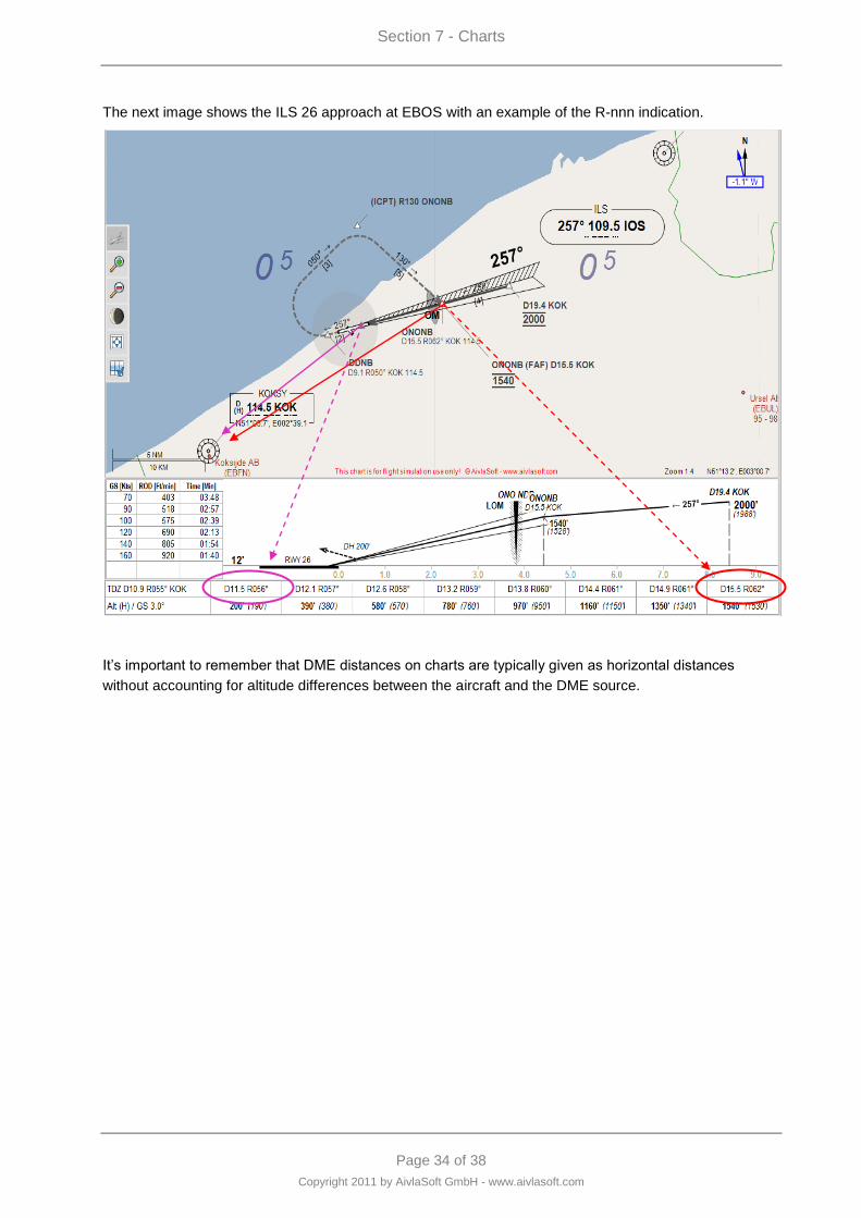
Section 7 - Charts
Page 34 of 38
Copyright 2011 by AivlaSoft GmbH - www.aivlasoft.com
The next image shows the ILS 26 approach at EBOS with an example of the R-nnn indication.
It‟s important to remember that DME distances on charts are typically given as horizontal distances
without accounting for altitude differences between the aircraft and the DME source.
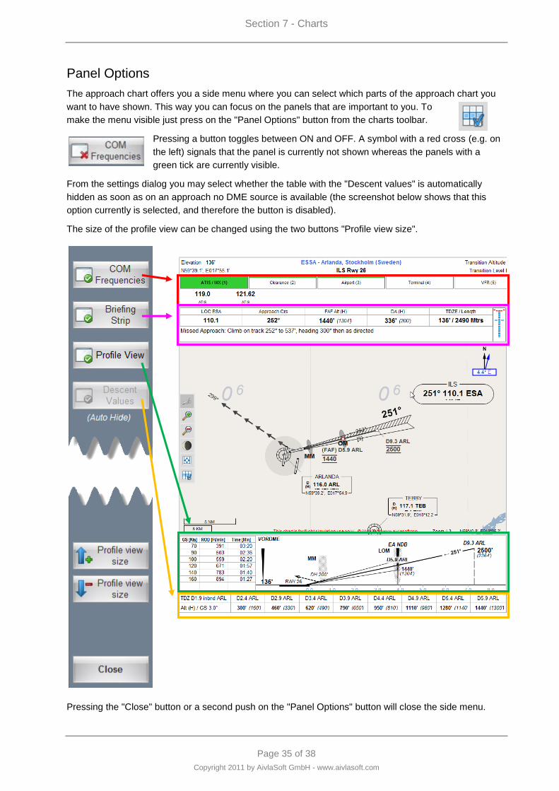
Section 7 - Charts
Page 35 of 38
Copyright 2011 by AivlaSoft GmbH - www.aivlasoft.com
Panel Options
The approach chart offers you a side menu where you can select which parts of the approach chart you
want to have shown. This way you can focus on the panels that are important to you. To
make the menu visible just press on the "Panel Options" button from the charts toolbar.
Pressing a button toggles between ON and OFF. A symbol with a red cross (e.g. on
the left) signals that the panel is currently not shown whereas the panels with a
green tick are currently visible.
From the settings dialog you may select whether the table with the "Descent values" is automatically
hidden as soon as on an approach no DME source is available (the screenshot below shows that this
option currently is selected, and therefore the button is disabled).
The size of the profile view can be changed using the two buttons "Profile view size".
Pressing the "Close" button or a second push on the "Panel Options" button will close the side menu.
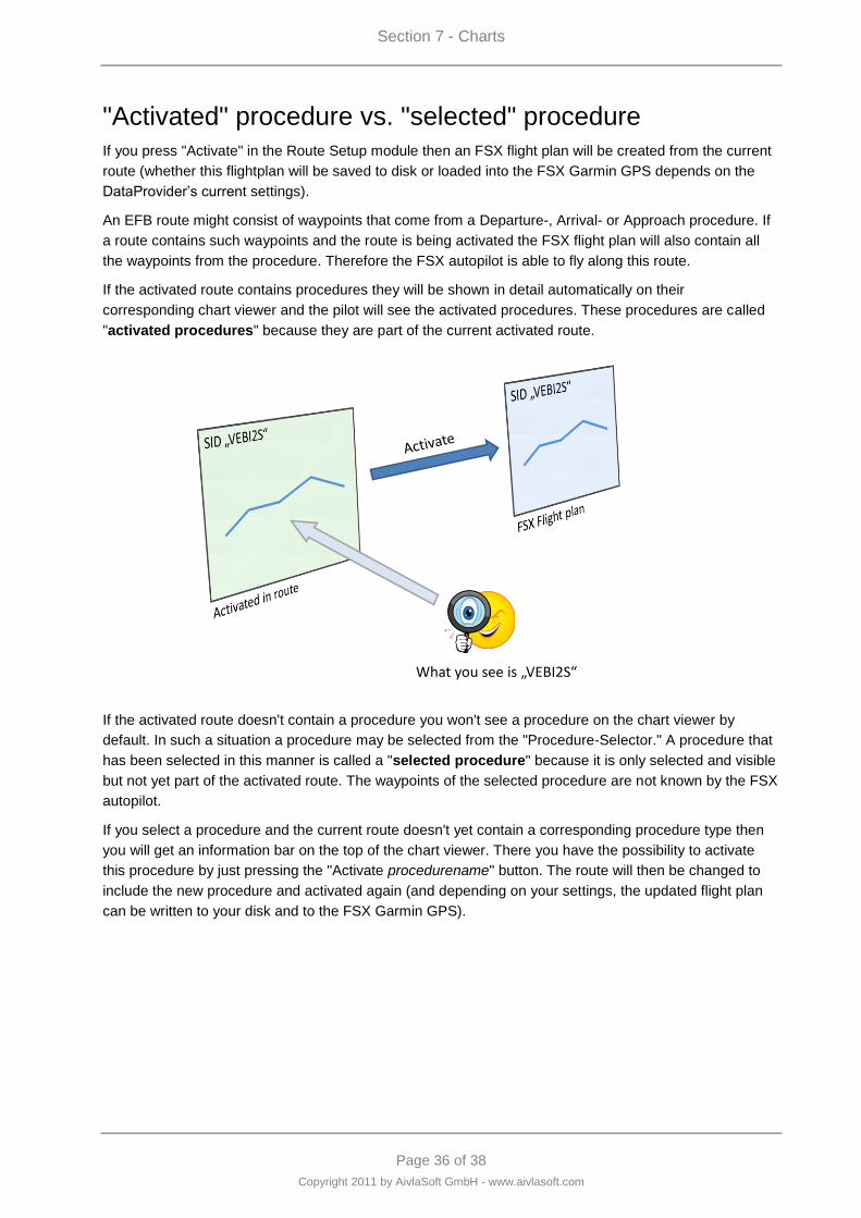
Section 7 - Charts
Page 36 of 38
Copyright 2011 by AivlaSoft GmbH - www.aivlasoft.com
"Activated" procedure vs. "selected" procedure
If you press "Activate" in the Route Setup module then an FSX flight plan will be created from the current
route (whether this flightplan will be saved to disk or loaded into the FSX Garmin GPS depends on the
DataProvider‟s current settings).
An EFB route might consist of waypoints that come from a Departure-, Arrival- or Approach procedure. If
a route contains such waypoints and the route is being activated the FSX flight plan will also contain all
the waypoints from the procedure. Therefore the FSX autopilot is able to fly along this route.
If the activated route contains procedures they will be shown in detail automatically on their
corresponding chart viewer and the pilot will see the activated procedures. These procedures are called
"activated procedures" because they are part of the current activated route.
What you see is „VEBI2S“
If the activated route doesn't contain a procedure you won't see a procedure on the chart viewer by
default. In such a situation a procedure may be selected from the "Procedure-Selector." A procedure that
has been selected in this manner is called a "selected procedure" because it is only selected and visible
but not yet part of the activated route. The waypoints of the selected procedure are not known by the FSX
autopilot.
If you select a procedure and the current route doesn't yet contain a corresponding procedure type then
you will get an information bar on the top of the chart viewer. There you have the possibility to activate
this procedure by just pressing the "Activate procedurename" button. The route will then be changed to
include the new procedure and activated again (and depending on your settings, the updated flight plan
can be written to your disk and to the FSX Garmin GPS).
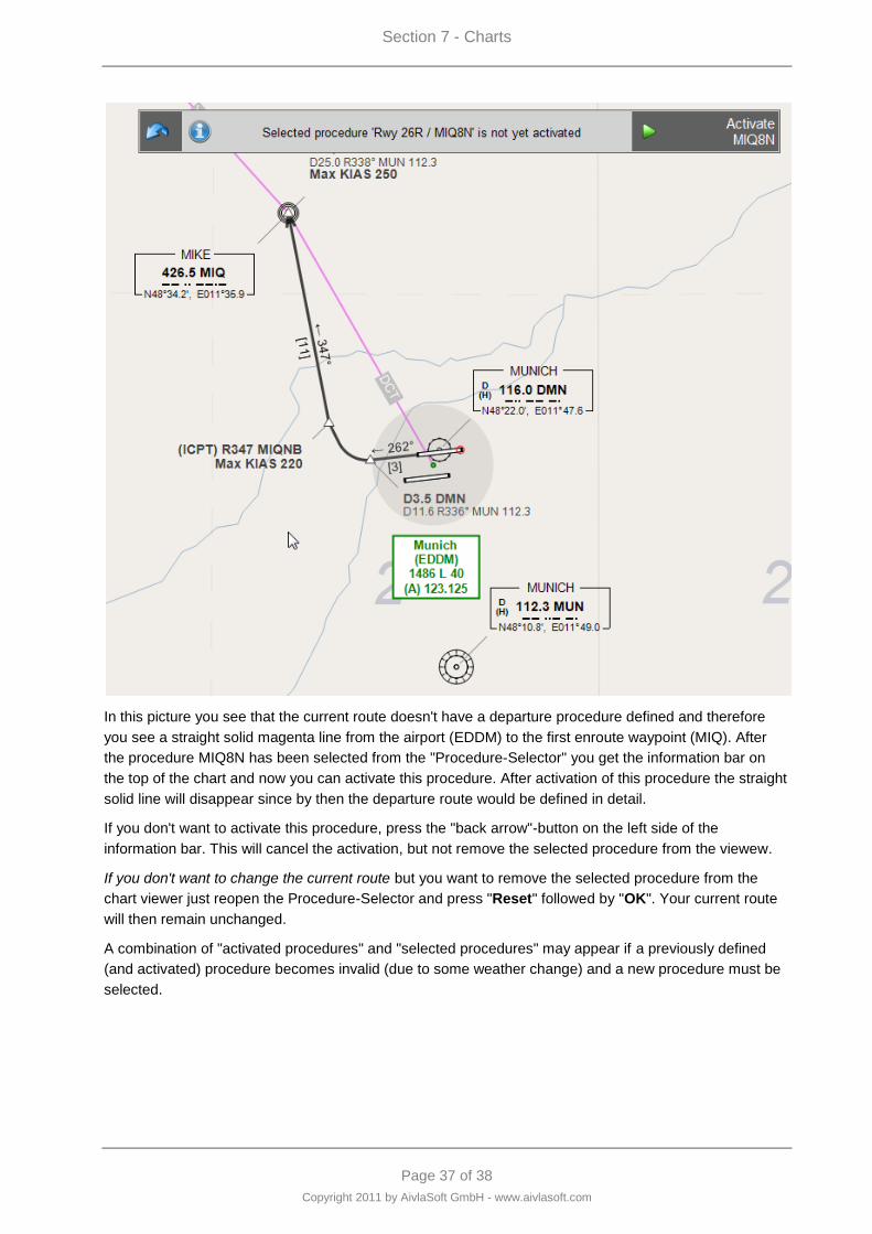
Section 7 - Charts
Page 37 of 38
Copyright 2011 by AivlaSoft GmbH - www.aivlasoft.com
In this picture you see that the current route doesn't have a departure procedure defined and therefore
you see a straight solid magenta line from the airport (EDDM) to the first enroute waypoint (MIQ). After
the procedure MIQ8N has been selected from the "Procedure-Selector" you get the information bar on
the top of the chart and now you can activate this procedure. After activation of this procedure the straight
solid line will disappear since by then the departure route would be defined in detail.
If you don't want to activate this procedure, press the "back arrow"-button on the left side of the
information bar. This will cancel the activation, but not remove the selected procedure from the viewew.
If you don't want to change the current route but you want to remove the selected procedure from the
chart viewer just reopen the Procedure-Selector and press "Reset" followed by "OK". Your current route
will then remain unchanged.
A combination of "activated procedures" and "selected procedures" may appear if a previously defined
(and activated) procedure becomes invalid (due to some weather change) and a new procedure must be
selected.
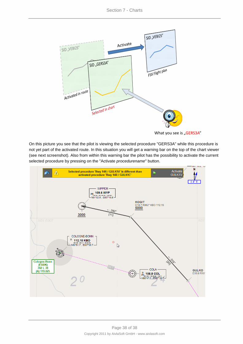
Section 7 - Charts
Page 38 of 38
Copyright 2011 by AivlaSoft GmbH - www.aivlasoft.com
What you see is „GERS3A“
On this picture you see that the pilot is viewing the selected procedure "GERS3A" while this procedure is
not yet part of the activated route. In this situation you will get a warning bar on the top of the chart viewer
(see next screenshot). Also from within this warning bar the pilot has the possibility to activate the current
selected procedure by pressing on the "Activate procedurename" button.

Page 1 of 17
Copyright 2011 by AivlaSoft GmbH - www.aivlasoft.com
Section 8 - Flight Information System
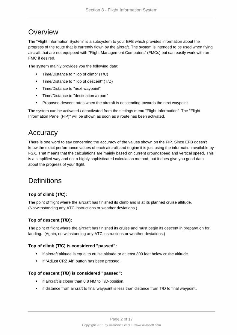
Section 8 - Flight Information System
Page 2 of 17
Copyright 2011 by AivlaSoft GmbH - www.aivlasoft.com
Overview
The "Flight Information System" is a subsystem to your EFB which provides information about the
progress of the route that is currently flown by the aircraft. The system is intended to be used when flying
aircraft that are not equipped with "Flight Management Computers" (FMCs) but can easily work with an
FMC if desired.
The system mainly provides you the following data:
Time/Distance to "Top of climb" (T/C)
Time/Distance to "Top of descent" (T/D)
Time/Distance to "next waypoint"
Time/Distance to "destination airport"
Proposed descent rates when the aircraft is descending towards the next waypoint
The system can be activated / deactivated from the settings menu "Flight Information". The "Flight
Information Panel (FIP)" will be shown as soon as a route has been activated.
Accuracy
There is one word to say concerning the accuracy of the values shown on the FIP. Since EFB doesn't
know the exact performance values of each aircraft and engine it is just using the information available by
FSX. That means that the calculations are mainly based on current groundspeed and vertical speed. This
is a simplified way and not a highly sophisticated calculation method, but it does give you good data
about the progress of your flight.
Definitions
Top of climb (T/C):
The point of flight where the aircraft has finished its climb and is at its planned cruise altitude.
(Notwithstanding any ATC instructions or weather deviations.)
Top of descent (T/D):
The point of flight where the aircraft has finished its cruise and must begin its descent in preparation for
landing. (Again, notwithstanding any ATC instructions or weather deviations.)
Top of climb (T/C) is considered "passed":
if aircraft altitude is equal to cruise altitude or at least 300 feet below cruise altitude.
if "Adjust CRZ Alt" button has been pressed.
Top of descent (T/D) is considered "passed":
if aircraft is closer than 0.8 NM to T/D-position.
if distance from aircraft to final waypoint is less than distance from T/D to final waypoint.

Section 8 - Flight Information System
Page 3 of 17
Copyright 2011 by AivlaSoft GmbH - www.aivlasoft.com
Observation of "altitude deviation" is active:
as soon as T/C has been passed.
Deviation will be indicated:
a) before T/D has been passed
if aircraft is higher or lower than 300 feet above/below cruise altitude.
b) after T/D has been passed
if aircraft is higher or lower than 50 feet above/below nominal descent path.
if the deviation is more than +/- 100 feet, a red arrow can show whether you have to increase or
decrease your descent rate to get back to the nominal path.
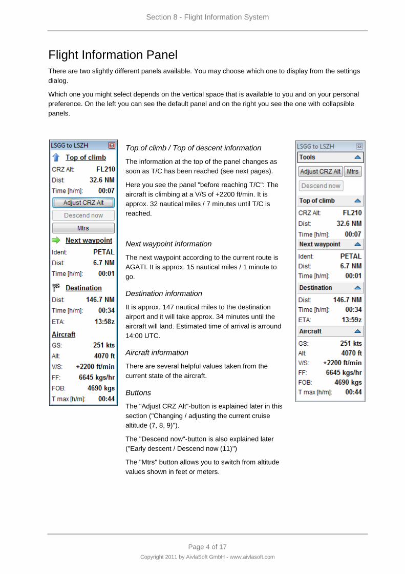
Section 8 - Flight Information System
Page 4 of 17
Copyright 2011 by AivlaSoft GmbH - www.aivlasoft.com
Flight Information Panel
There are two slightly different panels available. You may choose which one to display from the settings
dialog.
Which one you might select depends on the vertical space that is available to you and on your personal
preference. On the left you can see the default panel and on the right you see the one with collapsible
panels.
Top of climb / Top of descent information
The information at the top of the panel changes as
soon as T/C has been reached (see next pages).
Here you see the panel "before reaching T/C": The
aircraft is climbing at a V/S of +2200 ft/min. It is
approx. 32 nautical miles / 7 minutes until T/C is
reached.
Next waypoint information
The next waypoint according to the current route is
AGATI. It is approx. 15 nautical miles / 1 minute to
go.
Destination information
It is approx. 147 nautical miles to the destination
airport and it will take approx. 34 minutes until the
aircraft will land. Estimated time of arrival is arround
14:00 UTC.
Aircraft information
There are several helpful values taken from the
current state of the aircraft.
Buttons
The "Adjust CRZ Alt"-button is explained later in this
section ("Changing / adjusting the current cruise
altitude (7, 8, 9)").
The "Descend now"-button is also explained later
("Early descent / Descend now (11)")
The "Mtrs" button allows you to switch from altitude
values shown in feet or meters.
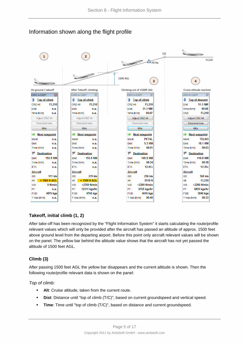
Section 8 - Flight Information System
Page 5 of 17
Copyright 2011 by AivlaSoft GmbH - www.aivlasoft.com
Information shown along the flight profile
1500 AGL
On ground / takeoff
PETAL
T/C
FL210
After Takeoff, climbing Climbing out of 1500ft AGL Cruise altitude reached
1 2
3 4
Takeoff, initial climb (1, 2)
After take-off has been recognized by the "Flight Information System" it starts calculating the route/profile
relevant values which will only be provided after the aircraft has passed an altitude of approx. 1500 feet
above ground level from the departing airport. Before this point only aircraft relevant values will be shown
on the panel. The yellow bar behind the altitude value shows that the aircraft has not yet passed the
altitude of 1500 feet AGL.
Climb (3)
After passing 1500 feet AGL the yellow bar disappears and the current altitude is shown. Then the
following route/profile relevant data is shown on the panel:
Top of climb:
Alt: Cruise altitude, taken from the current route.
Dist: Distance until "top of climb (T/C)", based on current groundspeed and vertical speed.
Time: Time until "top of climb (T/C)", based on distance and current groundspeed.
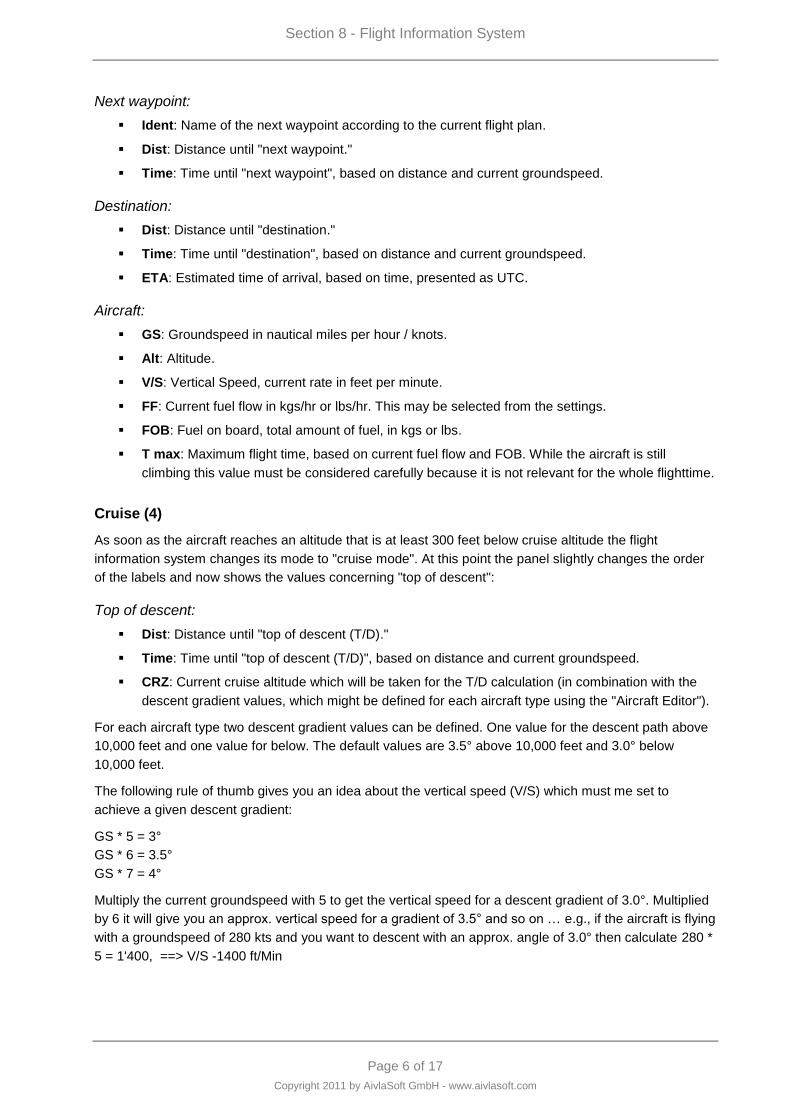
Section 8 - Flight Information System
Page 6 of 17
Copyright 2011 by AivlaSoft GmbH - www.aivlasoft.com
Next waypoint:
Ident: Name of the next waypoint according to the current flight plan.
Dist: Distance until "next waypoint."
Time: Time until "next waypoint", based on distance and current groundspeed.
Destination:
Dist: Distance until "destination."
Time: Time until "destination", based on distance and current groundspeed.
ETA: Estimated time of arrival, based on time, presented as UTC.
Aircraft:
GS: Groundspeed in nautical miles per hour / knots.
Alt: Altitude.
V/S: Vertical Speed, current rate in feet per minute.
FF: Current fuel flow in kgs/hr or lbs/hr. This may be selected from the settings.
FOB: Fuel on board, total amount of fuel, in kgs or lbs.
T max: Maximum flight time, based on current fuel flow and FOB. While the aircraft is still
climbing this value must be considered carefully because it is not relevant for the whole flighttime.
Cruise (4)
As soon as the aircraft reaches an altitude that is at least 300 feet below cruise altitude the flight
information system changes its mode to "cruise mode". At this point the panel slightly changes the order
of the labels and now shows the values concerning "top of descent":
Top of descent:
Dist: Distance until "top of descent (T/D)."
Time: Time until "top of descent (T/D)", based on distance and current groundspeed.
CRZ: Current cruise altitude which will be taken for the T/D calculation (in combination with the
descent gradient values, which might be defined for each aircraft type using the "Aircraft Editor").
For each aircraft type two descent gradient values can be defined. One value for the descent path above
10,000 feet and one value for below. The default values are 3.5° above 10,000 feet and 3.0° below
10,000 feet.
The following rule of thumb gives you an idea about the vertical speed (V/S) which must me set to
achieve a given descent gradient:
GS * 5 = 3°
GS * 6 = 3.5°
GS * 7 = 4°
Multiply the current groundspeed with 5 to get the vertical speed for a descent gradient of 3.0°. Multiplied
by 6 it will give you an approx. vertical speed for a gradient of 3.5° and so on … e.g., if the aircraft is flying
with a groundspeed of 280 kts and you want to descent with an approx. angle of 3.0° then calculate 280 *
5 = 1'400, ==> V/S -1400 ft/Min
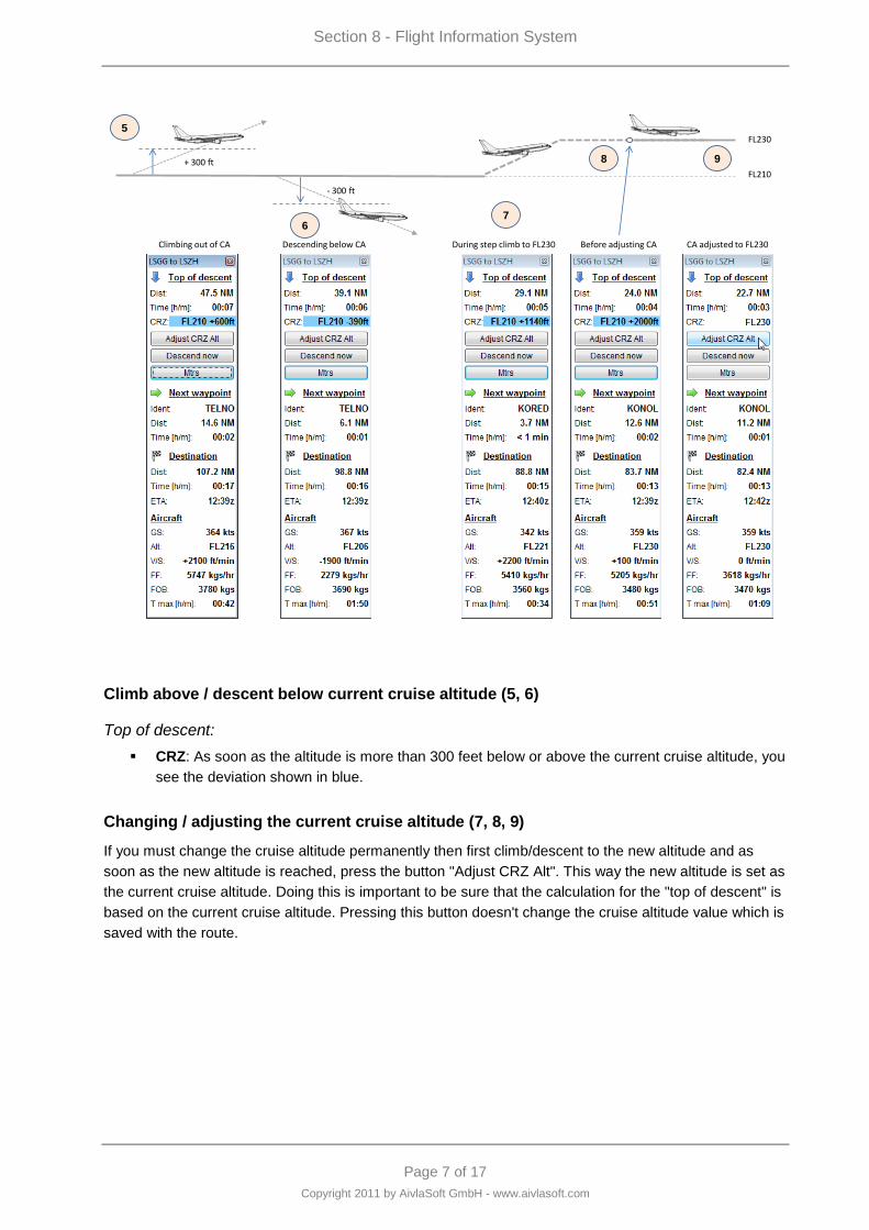
Section 8 - Flight Information System
Page 7 of 17
Copyright 2011 by AivlaSoft GmbH - www.aivlasoft.com
- 300 ft
Climbing out of CA
FL210
+ 300 ft
Descending below CA
FL230
During step climb to FL230 Before adjusting CA CA adjusted to FL230
5
67
8 9
Climb above / descent below current cruise altitude (5, 6)
Top of descent:
CRZ: As soon as the altitude is more than 300 feet below or above the current cruise altitude, you
see the deviation shown in blue.
Changing / adjusting the current cruise altitude (7, 8, 9)
If you must change the cruise altitude permanently then first climb/descent to the new altitude and as
soon as the new altitude is reached, press the button "Adjust CRZ Alt". This way the new altitude is set as
the current cruise altitude. Doing this is important to be sure that the calculation for the "top of descent" is
based on the current cruise altitude. Pressing this button doesn't change the cruise altitude value which is
saved with the route.
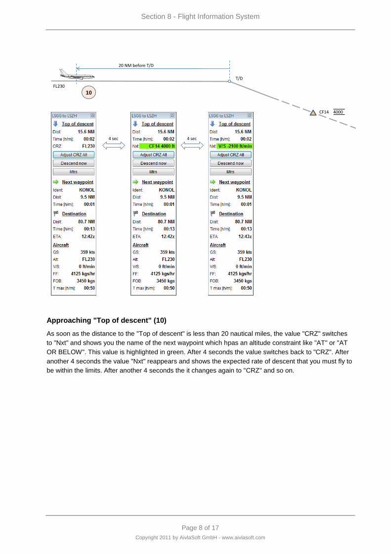
Section 8 - Flight Information System
Page 8 of 17
Copyright 2011 by AivlaSoft GmbH - www.aivlasoft.com
FL230
T/D
20 NM before T/D
CF14 4000
4 sec
10
4 sec
Approaching "Top of descent" (10)
As soon as the distance to the "Top of descent" is less than 20 nautical miles, the value "CRZ" switches
to "Nxt" and shows you the name of the next waypoint which hpas an altitude constraint like "AT" or "AT
OR BELOW". This value is highlighted in green. After 4 seconds the value switches back to "CRZ". After
another 4 seconds the value "Nxt" reappears and shows the expected rate of descent that you must fly to
be within the limits. After another 4 seconds the it changes again to "CRZ" and so on.
Section 8 - Flight Information System
Page 9 of 17
Copyright 2011 by AivlaSoft GmbH - www.aivlasoft.com
Early descent / Descend now (11)
You‟re nearing the end of a long flight. The weather is fine, your passengers are mostly asleep, your First
Officer is in the galley, fetching coffee. You look over to your EFB and notice to expect TOD in 27nm.
Suddenly your comms come alive, “Castle Air 231, descend to Flight Level 220.”
Not now, you say to yourself. EFB hasn’t given me a Rate of Descent yet.
But it will. Just press the “Descend Now” button on the FIP and the Flight Information System will
calculate a descent from this point to your first altitude constraint.
FL230
T/D
CF14 4000
Early descent
11
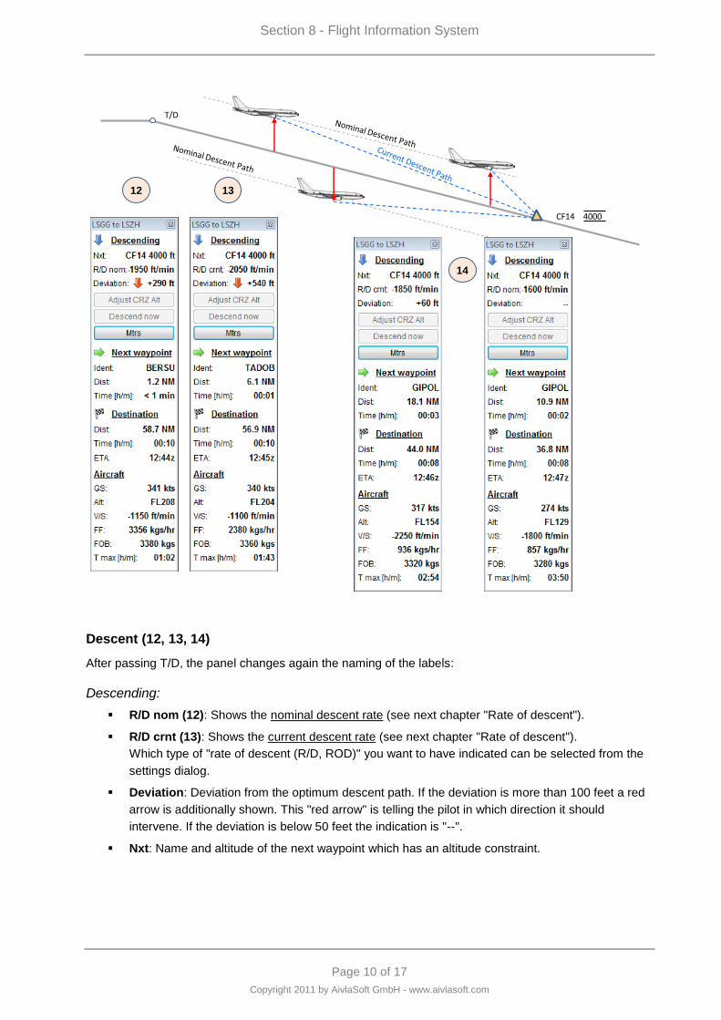
Section 8 - Flight Information System
Page 10 of 17
Copyright 2011 by AivlaSoft GmbH - www.aivlasoft.com
T/D
CF14 4000
12 13
14
Descent (12, 13, 14)
After passing T/D, the panel changes again the naming of the labels:
Descending:
R/D nom (12): Shows the nominal descent rate (see next chapter "Rate of descent").
R/D crnt (13): Shows the current descent rate (see next chapter "Rate of descent").
Which type of "rate of descent (R/D, ROD)" you want to have indicated can be selected from the
settings dialog.
Deviation: Deviation from the optimum descent path. If the deviation is more than 100 feet a red
arrow is additionally shown. This "red arrow" is telling the pilot in which direction it should
intervene. If the deviation is below 50 feet the indication is "--".
Nxt: Name and altitude of the next waypoint which has an altitude constraint.
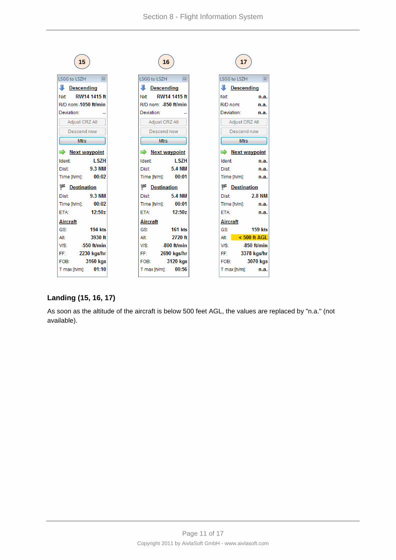
Section 8 - Flight Information System
Page 11 of 17
Copyright 2011 by AivlaSoft GmbH - www.aivlasoft.com
15 16 17
Landing (15, 16, 17)
As soon as the altitude of the aircraft is below 500 feet AGL, the values are replaced by "n.a." (not
available).
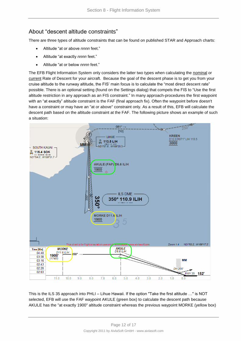
Section 8 - Flight Information System
Page 12 of 17
Copyright 2011 by AivlaSoft GmbH - www.aivlasoft.com
About “descent altitude constraints”
There are three types of altitude constraints that can be found on published STAR and Approach charts:
Altitude “at or above nnnn feet.”
Altitude “at exactly nnnn feet.”
Altitude “at or below nnnn feet.”
The EFB Flight Information System only considers the latter two types when calculating the nominal or
current Rate of Descent for your aircraft. Because the goal of the descent phase is to get you from your
cruise altitude to the runway altitude, the FIS‟ main focus is to calculate the “most direct descent rate”
possible. There is an optional setting (found on the Settings dialog) that compels the FIS to “Use the first
altitude restriction in any approach as an FIS constraint.” In many approach-procedures the first waypoint
with an “at exactly” altitude constraint is the FAF (final approach fix). Often the waypoint before doesn't
have a constraint or may have an "at or above" constraint only. As a result of this, EFB will calculate the
descent path based on the altitude constraint at the FAF. The following picture shows an example of such
a situation:
This is the ILS 35 approach into PHLI – Lihue Hawaii. If the option "Take the first altitude …" is NOT
selected, EFB will use the FAF waypoint AKULE (green box) to calculate the descent path because
AKULE has the "at exactly 1900" altitude constraint whereas the previous waypoint MORKE (yellow box)
Section 8 - Flight Information System
Page 13 of 17
Copyright 2011 by AivlaSoft GmbH - www.aivlasoft.com
is "at or above 1900." This common altitude level (1900 feet here) is important to consider when starting
an approach.
For many approaches, this altitude is called the “Intercept Altitude,” the “Intermediate Altitude,” the
“Approach Gate Altitude,” or the “Platform Altitude.” Whatever you call it, it is the published altitude at
which pilots are expected to intercept the real (or synthetic) glideslope for final approach. (Although on
any given approach, ATC may have their own idea of what altitude a pilot should use for interception.)
So in this case it would be better if the EFB descent target waypoint were MORKE at 1900, since we want
to come in under the glideslope. With the option "Take the first altitude …" selected, EFB will use MORKE
as the descent target waypoint – the “approach gate” – for this approach. If the option were not selected,
EFB will use AKULE as the descent target waypoint.
If you are flying a non-published approach – either a pattern approach or a direct visual approach – the
FIS‟ Rate of Descent will be calculated to bring you to the runway altitude.
As in all cases it is up to the Pilot in Command to ensure their aircraft meets minimum altitude restrictions
for obstacles and terrain, as well as for pattern altitude entry.
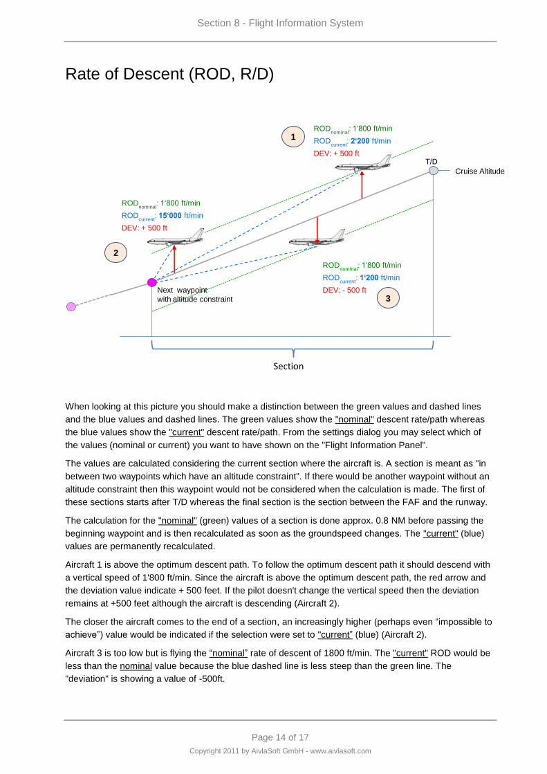
Section 8 - Flight Information System
Page 14 of 17
Copyright 2011 by AivlaSoft GmbH - www.aivlasoft.com
Rate of Descent (ROD, R/D)
DEV: - 500 ft
DEV: + 500 ft
DEV: + 500 ft
RODcurrent
: 2„200 ft/min
RODcurrent
: 15„000 ft/min
RODcurrent
: 1„200 ft/min
Cruise Altitude
T/D
Next waypoint
with altitude constraint
RODnominal
: 1„800 ft/min
RODnominal
: 1„800 ft/min
RODnominal
: 1„800 ft/min
Section
SectionSectionSection
FAF
T/D
1
2
3
When looking at this picture you should make a distinction between the green values and dashed lines
and the blue values and dashed lines. The green values show the "nominal" descent rate/path whereas
the blue values show the "current" descent rate/path. From the settings dialog you may select which of
the values (nominal or current) you want to have shown on the "Flight Information Panel".
The values are calculated considering the current section where the aircraft is. A section is meant as "in
between two waypoints which have an altitude constraint". If there would be another waypoint without an
altitude constraint then this waypoint would not be considered when the calculation is made. The first of
these sections starts after T/D whereas the final section is the section between the FAF and the runway.
The calculation for the "nominal" (green) values of a section is done approx. 0.8 NM before passing the
beginning waypoint and is then recalculated as soon as the groundspeed changes. The "current" (blue)
values are permanently recalculated.
Aircraft 1 is above the optimum descent path. To follow the optimum descent path it should descend with
a vertical speed of 1'800 ft/min. Since the aircraft is above the optimum descent path, the red arrow and
the deviation value indicate + 500 feet. If the pilot doesn't change the vertical speed then the deviation
remains at +500 feet although the aircraft is descending (Aircraft 2).
The closer the aircraft comes to the end of a section, an increasingly higher (perhaps even “impossible to
achieve”) value would be indicated if the selection were set to "current” (blue) (Aircraft 2).
Aircraft 3 is too low but is flying the “nominal” rate of descent of 1800 ft/min. The "current" ROD would be
less than the nominal value because the blue dashed line is less steep than the green line. The
"deviation" is showing a value of -500ft.
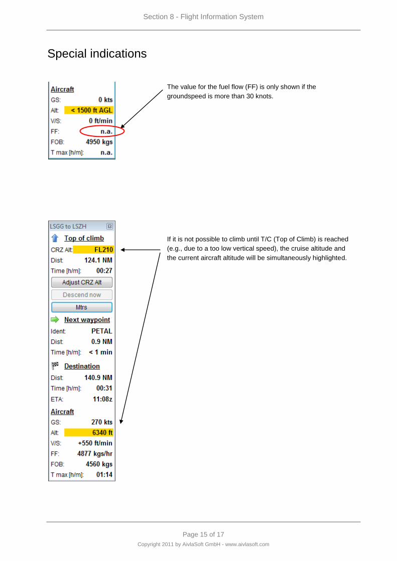
Section 8 - Flight Information System
Page 15 of 17
Copyright 2011 by AivlaSoft GmbH - www.aivlasoft.com
Special indications
The value for the fuel flow (FF) is only shown if the
groundspeed is more than 30 knots.
If it is not possible to climb until T/C (Top of Climb) is reached
(e.g., due to a too low vertical speed), the cruise altitude and
the current aircraft altitude will be simultaneously highlighted.
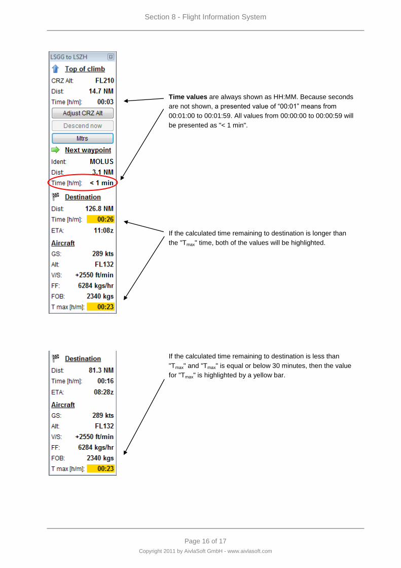
Section 8 - Flight Information System
Page 16 of 17
Copyright 2011 by AivlaSoft GmbH - www.aivlasoft.com
Time values are always shown as HH:MM. Because seconds
are not shown, a presented value of “00:01” means from
00:01:00 to 00:01:59. All values from 00:00:00 to 00:00:59 will
be presented as "< 1 min".
If the calculated time remaining to destination is longer than
the "Tmax" time, both of the values will be highlighted.
If the calculated time remaining to destination is less than
"Tmax" and "Tmax" is equal or below 30 minutes, then the value
for "Tmax" is highlighted by a yellow bar.
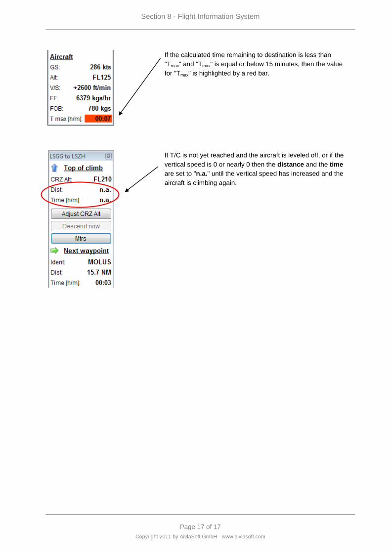
Section 8 - Flight Information System
Page 17 of 17
Copyright 2011 by AivlaSoft GmbH - www.aivlasoft.com
If the calculated time remaining to destination is less than
"Tmax" and "Tmax" is equal or below 15 minutes, then the value
for "Tmax" is highlighted by a red bar.
If T/C is not yet reached and the aircraft is leveled off, or if the
vertical speed is 0 or nearly 0 then the distance and the time
are set to "n.a." until the vertical speed has increased and the
aircraft is climbing again.


Page 1 of 6
Copyright 2011 by AivlaSoft GmbH - www.aivlasoft.com
Section 9 - METAR
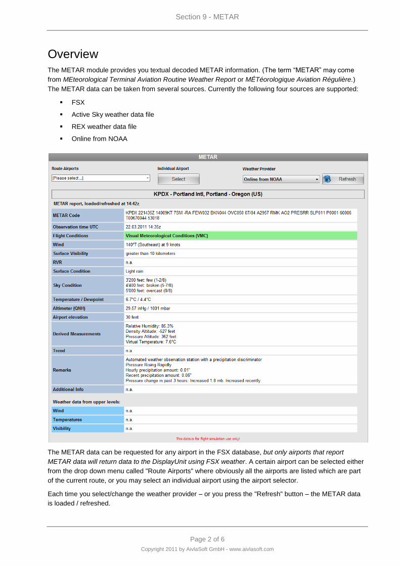
Section 9 - METAR
Page 2 of 6
Copyright 2011 by AivlaSoft GmbH - www.aivlasoft.com
Overview
The METAR module provides you textual decoded METAR information. (The term “METAR” may come
from MEteorological Terminal Aviation Routine Weather Report or MÉTéorologique Aviation Régulière.)
The METAR data can be taken from several sources. Currently the following four sources are supported:
FSX
Active Sky weather data file
REX weather data file
Online from NOAA
The METAR data can be requested for any airport in the FSX database, but only airports that report
METAR data will return data to the DisplayUnit using FSX weather. A certain airport can be selected either
from the drop down menu called "Route Airports" where obviously all the airports are listed which are part
of the current route, or you may select an individual airport using the airport selector.
Each time you select/change the weather provider – or you press the "Refresh" button – the METAR data
is loaded / refreshed.
Section 9 - METAR
Page 3 of 6
Copyright 2011 by AivlaSoft GmbH - www.aivlasoft.com
METAR Data Sources
EFB can read METAR data from three types of sources: from FSX when the simulator is running, from the
American National Weather Service – part of the government‟s National Oceanic and Atmospheric
Administration – and also from certain FSX add-on weather engines.
So which data source should you use?
FSX weather data has the advantage of precisely representing the weather conditions that are
currently being simulated in the area of – and in the areas surrounding – the user‟s aircraft.
However FSX sometimes only sets weather for a certain distance around the user – so if you‟re
planning a transcontinental or transoceanic route, FSX may not be able to provide the weather for
your destination. And if you‟re pre-planning a flight and haven‟t yet launched FSX, then FSX
weather will obviously not be available.
Data from NOAA is downloaded for each requested airport from a URL that is defined in the
DataProvider‟s Settings. Like weather engine data, NOAA data forms the basis for which FSX
“interprets” its own weather systems. Also like weather engine data, additional weather conditions
that don‟t necessarily exist in FSX are reported, which might help to give your next flight a bit of
“local flavor.”
Weather engine data is typically downloaded in a single batch by the engine itself, according to the
engines‟ own settings. When asked for this data, EFB looks for the appropriate file system path
(also defined in the DataProvider‟s Settings) and finds the current weather engine data file, and
then the data for the requested airport.
If you‟re preparing for takeoff or landing, then you might want to look at FSX weather data for two reasons:
it represents the data currently being simulated, and it shows upper-level winds / gusts / shear conditions /
temperatures / icing reports / visibility levels.
For destination / alternate planning, NOAA/weather-engine data would be the source you would want to
view. This data is available for all weather-reporting stations worldwide, plus it includes data beyond what
FSX uses – for example “trends” that describe what local weather reporters believe will occur.
If you use one of the two currently supported add-on FSX weather engines, then the data is probably
already on your FSX computer‟s hard drive so it would be available for you without making an extra Internet
connection. Otherwise, NOAA weather data is just a click away.
Finally, the source document used to guide us in METAR decoding is NOAA's Federal Meteorological
Handbook No.1.
Meaning of METAR data
For EFB‟s purposes, METAR data is divided into several areas – the listed surface conditions, conditions
and values that can be derived from the surface data, upper level conditions, and ancillary conditions.
Surface Conditions
Generally this is the weather you‟d feel if you were on the ramp, walking around your aircraft performing
your pre-flight checks. (You always perform a pre-flight, don’t you?). Essentially it‟s nothing more than the
temperature, dew point, winds, surface air pressure, how the sky appears from the ground, and any
precipitation falling on your head. (You always wear a pilot’s cap, don’t you?)
All of that data, plus the surface visibility (how far you can see towards the horizon) is modeled fairly well in
FSX. One bit of surface data that isn‟t used in FSX (and so it‟s only found in NOAA and weather engine
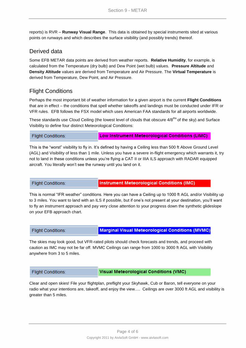
Section 9 - METAR
Page 4 of 6
Copyright 2011 by AivlaSoft GmbH - www.aivlasoft.com
reports) is RVR – Runway Visual Range. This data is obtained by special instruments sited at various
points on runways and which describes the surface visibility (and possibly trends) thereof.
Derived data
Some EFB METAR data points are derived from weather reports. Relative Humidity, for example, is
calculated from the Temperature (dry bulb) and Dew Point (wet bulb) values. Pressure Altitude and
Density Altitude values are derived from Temperature and Air Pressure. The Virtual Temperature is
derived from Temperature, Dew Point, and Air Pressure.
Flight Conditions
Perhaps the most important bit of weather information for a given airport is the current Flight Conditions
that are in effect – the conditions that spell whether takeoffs and landings must be conducted under IFR or
VFR rules. EFB follows the FSX model which uses American FAA standards for all airports worldwide.
These standards use Cloud Ceiling (the lowest level of clouds that obscure 4/8ths
of the sky) and Surface
Visibility to define four distinct Meteorological Conditions:
This is the “worst” visibility to fly in. It‟s defined by having a Ceiling less than 500 ft Above Ground Level
(AGL) and Visibility of less than 1 mile. Unless you have a severe in-flight emergency which warrants it, try
not to land in these conditions unless you‟re flying a CAT II or IIIA ILS approach with RADAR equipped
aircraft. You literally won‟t see the runway until you land on it.
This is normal “IFR weather” conditions. Here you can have a Ceiling up to 1000 ft AGL and/or Visibility up
to 3 miles. You want to land with an ILS if possible, but if one‟s not present at your destination, you‟ll want
to fly an instrument approach and pay very close attention to your progress down the synthetic glideslope
on your EFB approach chart.
The skies may look good, but VFR-rated pilots should check forecasts and trends, and proceed with
caution as IMC may not be far off. MVMC Ceilings can range from 1000 to 3000 ft AGL with Visibility
anywhere from 3 to 5 miles.
Clear and open skies! File your flightplan, preflight your Skyhawk, Cub or Baron, tell everyone on your
radio what your intentions are, takeoff, and enjoy the view…. Ceilings are over 3000 ft AGL and visibility is
greater than 5 miles.
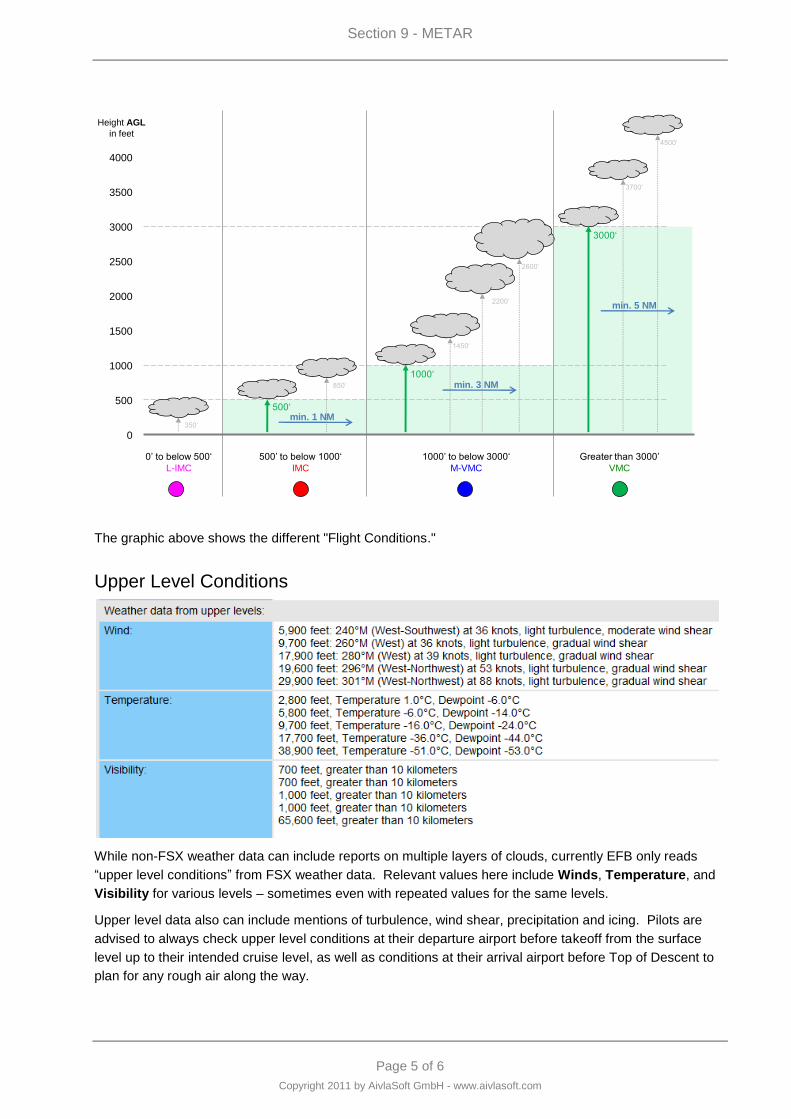
Section 9 - METAR
Page 5 of 6
Copyright 2011 by AivlaSoft GmbH - www.aivlasoft.com
0
500
1000
1500
2000
2500
3000
3500
4000
Height AGL
in feet
0‟ to below 500„
L-IMC
500‟ to below 1000„
IMC
500„
1000„
1000‟ to below 3000„
M-VMC
3000„
1450„
2200„
2600„
350„
850„
3700„
4500„
Greater than 3000‟
VMC
Aviation Flight Categories
min. 1 NM
min. 3 NM
min. 5 NM
The graphic above shows the different "Flight Conditions."
Upper Level Conditions
While non-FSX weather data can include reports on multiple layers of clouds, currently EFB only reads
“upper level conditions” from FSX weather data. Relevant values here include Winds, Temperature, and
Visibility for various levels – sometimes even with repeated values for the same levels.
Upper level data also can include mentions of turbulence, wind shear, precipitation and icing. Pilots are
advised to always check upper level conditions at their departure airport before takeoff from the surface
level up to their intended cruise level, as well as conditions at their arrival airport before Top of Descent to
plan for any rough air along the way.
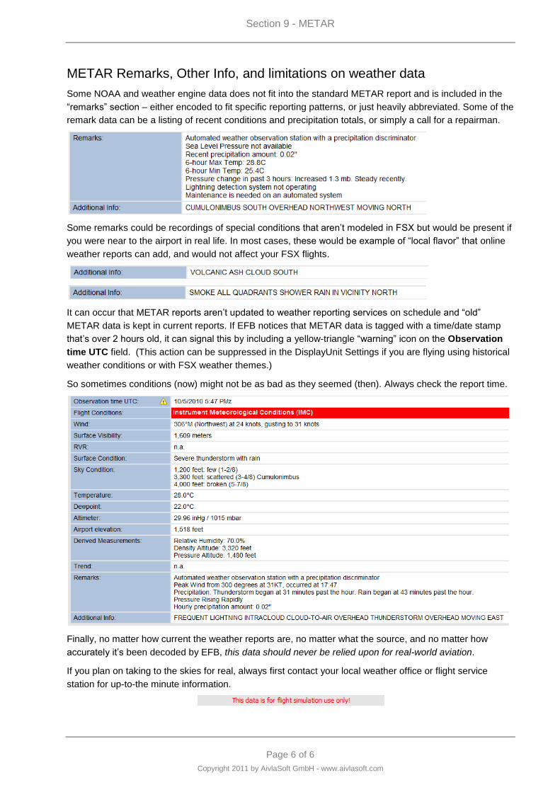
Section 9 - METAR
Page 6 of 6
Copyright 2011 by AivlaSoft GmbH - www.aivlasoft.com
METAR Remarks, Other Info, and limitations on weather data
Some NOAA and weather engine data does not fit into the standard METAR report and is included in the
“remarks” section – either encoded to fit specific reporting patterns, or just heavily abbreviated. Some of the
remark data can be a listing of recent conditions and precipitation totals, or simply a call for a repairman.
Some remarks could be recordings of special conditions that aren‟t modeled in FSX but would be present if
you were near to the airport in real life. In most cases, these would be example of “local flavor” that online
weather reports can add, and would not affect your FSX flights.
It can occur that METAR reports aren‟t updated to weather reporting services on schedule and “old”
METAR data is kept in current reports. If EFB notices that METAR data is tagged with a time/date stamp
that‟s over 2 hours old, it can signal this by including a yellow-triangle “warning” icon on the Observation
time UTC field. (This action can be suppressed in the DisplayUnit Settings if you are flying using historical
weather conditions or with FSX weather themes.)
So sometimes conditions (now) might not be as bad as they seemed (then). Always check the report time.
Finally, no matter how current the weather reports are, no matter what the source, and no matter how
accurately it‟s been decoded by EFB, this data should never be relied upon for real-world aviation.
If you plan on taking to the skies for real, always first contact your local weather office or flight service
station for up-to-the minute information.

Page 1 of 10
Copyright 2011 by AivlaSoft GmbH - www.aivlasoft.com
Section 10 - Flying "online"
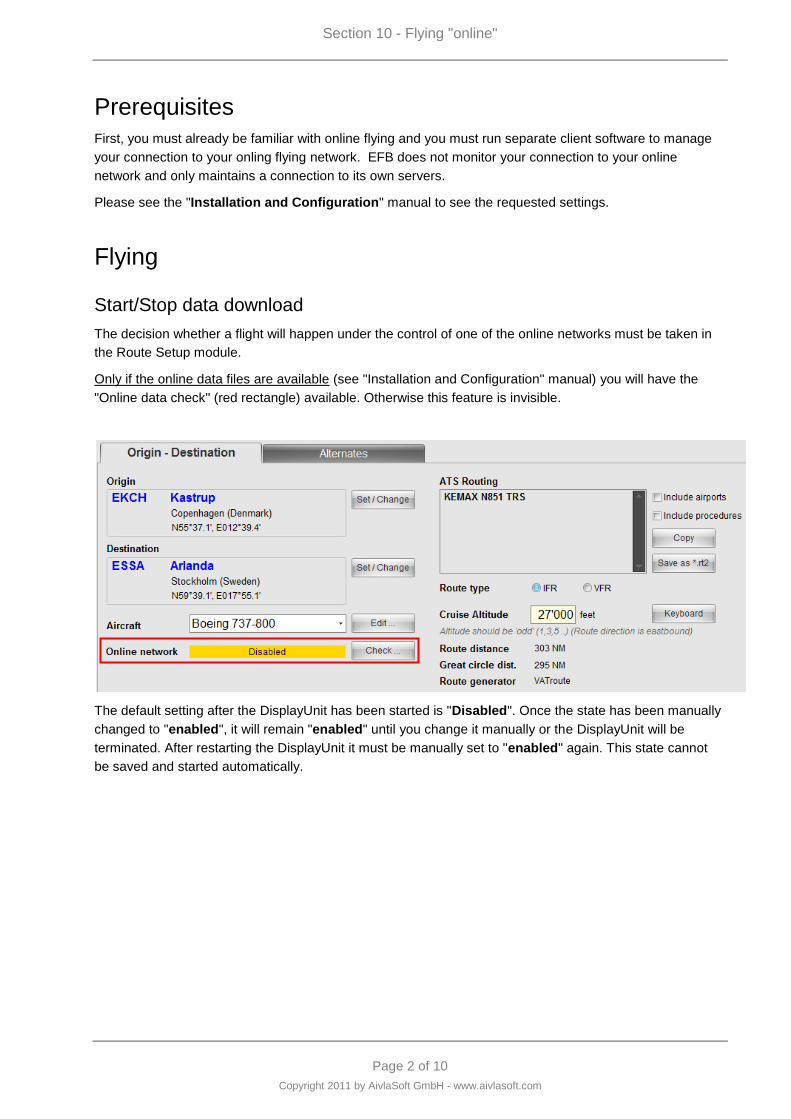
Section 10 - Flying "online"
Page 2 of 10
Copyright 2011 by AivlaSoft GmbH - www.aivlasoft.com
Prerequisites
First, you must already be familiar with online flying and you must run separate client software to manage
your connection to your onling flying network. EFB does not monitor your connection to your online
network and only maintains a connection to its own servers.
Please see the "Installation and Configuration" manual to see the requested settings.
Flying
Start/Stop data download
The decision whether a flight will happen under the control of one of the online networks must be taken in
the Route Setup module.
Only if the online data files are available (see "Installation and Configuration" manual) you will have the
"Online data check" (red rectangle) available. Otherwise this feature is invisible.
The default setting after the DisplayUnit has been started is "Disabled". Once the state has been manually
changed to "enabled", it will remain "enabled" until you change it manually or the DisplayUnit will be
terminated. After restarting the DisplayUnit it must be manually set to "enabled" again. This state cannot
be saved and started automatically.
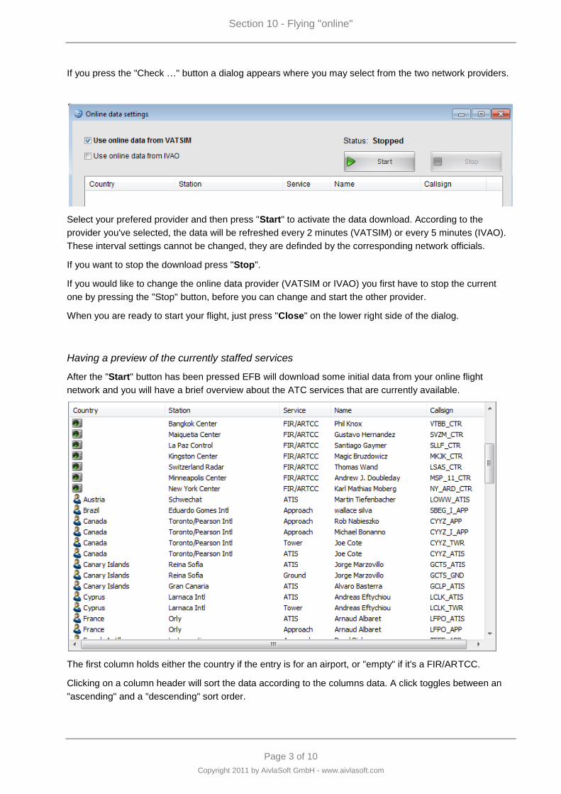
Section 10 - Flying "online"
Page 3 of 10
Copyright 2011 by AivlaSoft GmbH - www.aivlasoft.com
If you press the "Check …" button a dialog appears where you may select from the two network providers.
Select your prefered provider and then press "Start" to activate the data download. According to the
provider you've selected, the data will be refreshed every 2 minutes (VATSIM) or every 5 minutes (IVAO).
These interval settings cannot be changed, they are definded by the corresponding network officials.
If you want to stop the download press "Stop".
If you would like to change the online data provider (VATSIM or IVAO) you first have to stop the current
one by pressing the "Stop" button, before you can change and start the other provider.
When you are ready to start your flight, just press "Close" on the lower right side of the dialog.
Having a preview of the currently staffed services
After the "Start" button has been pressed EFB will download some initial data from your online flight
network and you will have a brief overview about the ATC services that are currently available.
The first column holds either the country if the entry is for an airport, or "empty" if it's a FIR/ARTCC.
Clicking on a column header will sort the data according to the columns data. A click toggles between an
"ascending" and a "descending" sort order.
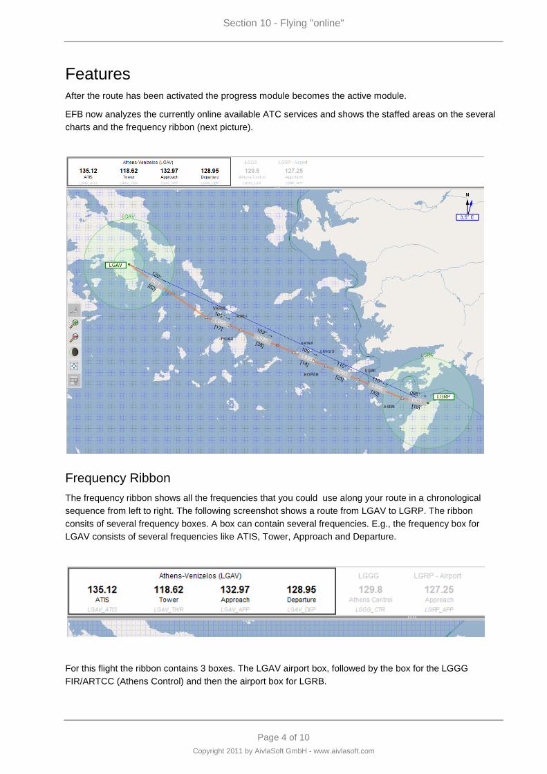
Section 10 - Flying "online"
Page 4 of 10
Copyright 2011 by AivlaSoft GmbH - www.aivlasoft.com
Features
After the route has been activated the progress module becomes the active module.
EFB now analyzes the currently online available ATC services and shows the staffed areas on the several
charts and the frequency ribbon (next picture).
Frequency Ribbon
The frequency ribbon shows all the frequencies that you could use along your route in a chronological
sequence from left to right. The following screenshot shows a route from LGAV to LGRP. The ribbon
consits of several frequency boxes. A box can contain several frequencies. E.g., the frequency box for
LGAV consists of several frequencies like ATIS, Tower, Approach and Departure.
For this flight the ribbon contains 3 boxes. The LGAV airport box, followed by the box for the LGGG
FIR/ARTCC (Athens Control) and then the airport box for LGRB.
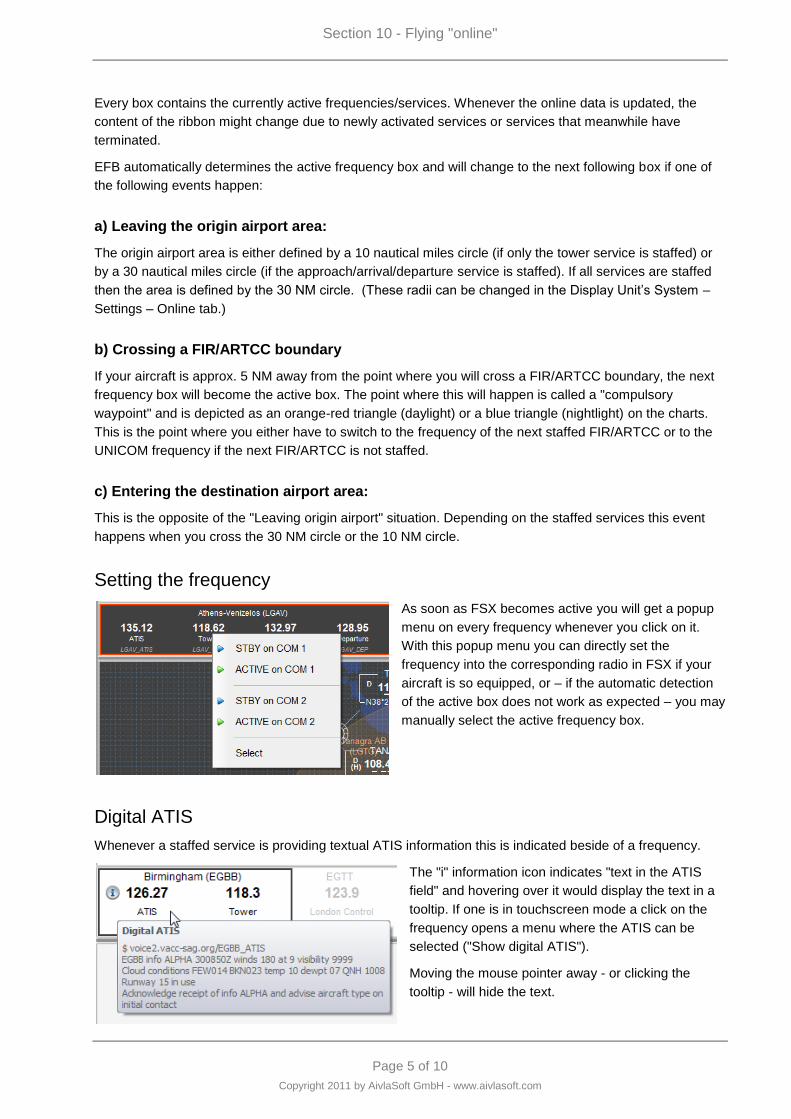
Section 10 - Flying "online"
Page 5 of 10
Copyright 2011 by AivlaSoft GmbH - www.aivlasoft.com
Every box contains the currently active frequencies/services. Whenever the online data is updated, the
content of the ribbon might change due to newly activated services or services that meanwhile have
terminated.
EFB automatically determines the active frequency box and will change to the next following box if one of
the following events happen:
a) Leaving the origin airport area:
The origin airport area is either defined by a 10 nautical miles circle (if only the tower service is staffed) or
by a 30 nautical miles circle (if the approach/arrival/departure service is staffed). If all services are staffed
then the area is defined by the 30 NM circle. (These radii can be changed in the Display Unit‟s System –
Settings – Online tab.)
b) Crossing a FIR/ARTCC boundary
If your aircraft is approx. 5 NM away from the point where you will cross a FIR/ARTCC boundary, the next
frequency box will become the active box. The point where this will happen is called a "compulsory
waypoint" and is depicted as an orange-red triangle (daylight) or a blue triangle (nightlight) on the charts.
This is the point where you either have to switch to the frequency of the next staffed FIR/ARTCC or to the
UNICOM frequency if the next FIR/ARTCC is not staffed.
c) Entering the destination airport area:
This is the opposite of the "Leaving origin airport" situation. Depending on the staffed services this event
happens when you cross the 30 NM circle or the 10 NM circle.
Setting the frequency
As soon as FSX becomes active you will get a popup
menu on every frequency whenever you click on it.
With this popup menu you can directly set the
frequency into the corresponding radio in FSX if your
aircraft is so equipped, or – if the automatic detection
of the active box does not work as expected – you may
manually select the active frequency box.
Digital ATIS
Whenever a staffed service is providing textual ATIS information this is indicated beside of a frequency.
The "i" information icon indicates "text in the ATIS
field" and hovering over it would display the text in a
tooltip. If one is in touchscreen mode a click on the
frequency opens a menu where the ATIS can be
selected ("Show digital ATIS").
Moving the mouse pointer away - or clicking the
tooltip - will hide the text.

Section 10 - Flying "online"
Page 6 of 10
Copyright 2011 by AivlaSoft GmbH - www.aivlasoft.com
Chart Details
On the charts the following items are depicted (colors may be changed in the settings).
The orange triangle ("gold" with nightlight)
represents a "compulsory waypoint". This is the
point where you should change the current
frequency to the next one to announce your flight
to the next ATC service.
From the user settings you can select the symbol
for the compulsory waypoints (triangle or circle).
A staffed FIR/ARTCC is covered by squared
dotted lines. Here you see that the FIR "LOVV" is
currently staffed.
Airports that offers online ATC are shown as one
or two concentric circles. The inner circle (a 10
NM range) is depicted if the TWR is staffed, the
outer circle (a 30 NM range) is depicted if either
the APP/ARR/DEP service is staffed.
On the left side you see that at EGSS and EGKK
the tower is staffed whereas at EGLL the tower
and approach/departure or arrival is staffed.
FIR/ARTCC is staffed
UIR is staffed. On VATSIM there are also UIRs
known (Upper information region). Commonly
this is an area that includes several FIRs below it
and it controls air traffic at higher levels (above
FL 245).
UIR and FIR is staffed.
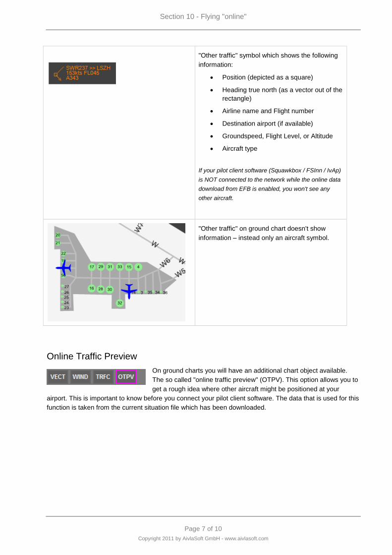
Section 10 - Flying "online"
Page 7 of 10
Copyright 2011 by AivlaSoft GmbH - www.aivlasoft.com
"Other traffic" symbol which shows the following
information:
Position (depicted as a square)
Heading true north (as a vector out of the
rectangle)
Airline name and Flight number
Destination airport (if available)
Groundspeed, Flight Level, or Altitude
Aircraft type
If your pilot client software (Squawkbox / FSInn / IvAp)
is NOT connected to the network while the online data
download from EFB is enabled, you won't see any
other aircraft.
"Other traffic" on ground chart doesn't show
information – instead only an aircraft symbol.
Online Traffic Preview
On ground charts you will have an additional chart object available.
The so called "online traffic preview" (OTPV). This option allows you to
get a rough idea where other aircraft might be positioned at your
airport. This is important to know before you connect your pilot client software. The data that is used for this
function is taken from the current situation file which has been downloaded.
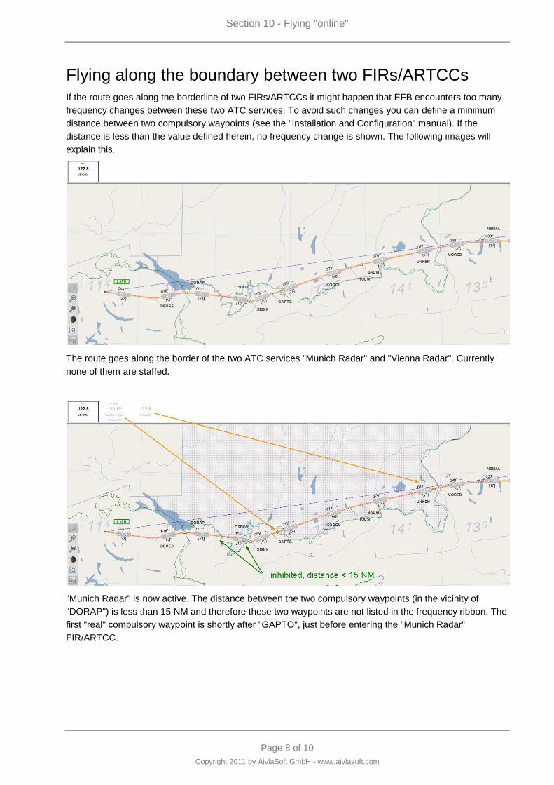
Section 10 - Flying "online"
Page 8 of 10
Copyright 2011 by AivlaSoft GmbH - www.aivlasoft.com
Flying along the boundary between two FIRs/ARTCCs
If the route goes along the borderline of two FIRs/ARTCCs it might happen that EFB encounters too many
frequency changes between these two ATC services. To avoid such changes you can define a minimum
distance between two compulsory waypoints (see the "Installation and Configuration" manual). If the
distance is less than the value defined herein, no frequency change is shown. The following images will
explain this.
The route goes along the border of the two ATC services "Munich Radar" and "Vienna Radar". Currently
none of them are staffed.
"Munich Radar" is now active. The distance between the two compulsory waypoints (in the vicinity of
"DORAP") is less than 15 NM and therefore these two waypoints are not listed in the frequency ribbon. The
first "real" compulsory waypoint is shortly after "GAPTO", just before entering the "Munich Radar"
FIR/ARTCC.
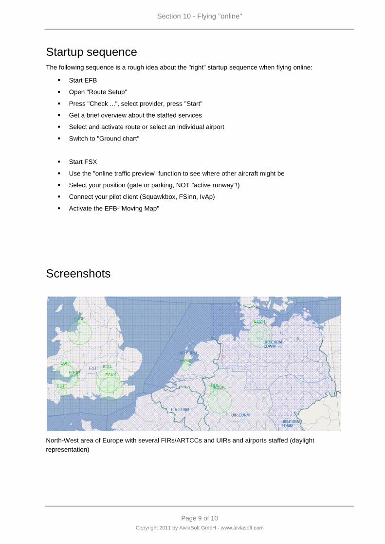
Section 10 - Flying "online"
Page 9 of 10
Copyright 2011 by AivlaSoft GmbH - www.aivlasoft.com
Startup sequence
The following sequence is a rough idea about the "right" startup sequence when flying online:
Start EFB
Open "Route Setup"
Press "Check ...", select provider, press "Start"
Get a brief overview about the staffed services
Select and activate route or select an individual airport
Switch to "Ground chart"
Start FSX
Use the "online traffic preview" function to see where other aircraft might be
Select your position (gate or parking, NOT "active runway"!)
Connect your pilot client (Squawkbox, FSInn, IvAp)
Activate the EFB-"Moving Map"
Screenshots
North-West area of Europe with several FIRs/ARTCCs and UIRs and airports staffed (daylight
representation)
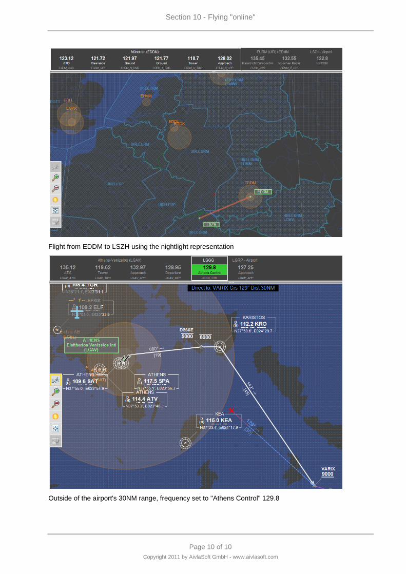
Section 10 - Flying "online"
Page 10 of 10
Copyright 2011 by AivlaSoft GmbH - www.aivlasoft.com
Flight from EDDM to LSZH using the nightlight representation
Outside of the airport's 30NM range, frequency set to "Athens Control" 129.8

Page 1 of 4
Copyright 2011 by AivlaSoft GmbH - www.aivlasoft.com
Section 11 - Flightlog
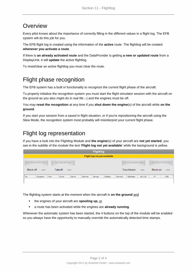
Section 11 - Flightlog
Page 2 of 4
Copyright 2011 by AivlaSoft GmbH - www.aivlasoft.com
Overview
Every pilot knows about the importance of correctly filling in the different values in a flight log. The EFB
system will do this job for you.
The EFB flight log is created using the information of the active route. The flightlog will be created
whenever you activate a route.
If there is an already activated route and the DataProvider is getting a new or updated route from a
DisplayUnit, it will update the active flightlog.
To reset/clear an active flightlog you must clear the route.
Flight phase recognition
The EFB system has a built in functionality to recognize the current flight phase of the aircraft.
To properly initialize the recognition system you must start the flight simulator session with the aircraft on
the ground as you also might do in real life ;-) and the engines must be off.
You may reset the recognition at any time if you shut down the engine(s) of the aircraft while on the
ground.
If you start your session from a saved in flight situation, or if you're repositioning the aircraft using the
Slew Mode, the recognition system most probably will misinterpret your current flight phase.
Flight log representation
If you have a look into the Flightlog Module and the engine(s) of your aircraft are not yet started, you
see in the subtitle of the module the text 'Flight log not yet available' while the background is yellow.
The flightlog system starts at the moment when the aircraft is on the ground and
the engines of your aircraft are spooling up, or
a route has been activated while the engines are already running.
Whenever the automatic system has been started, the 4 buttons on the top of the module will be enabled
so you always have the opportunity to manually override the automatically detected time stamps.
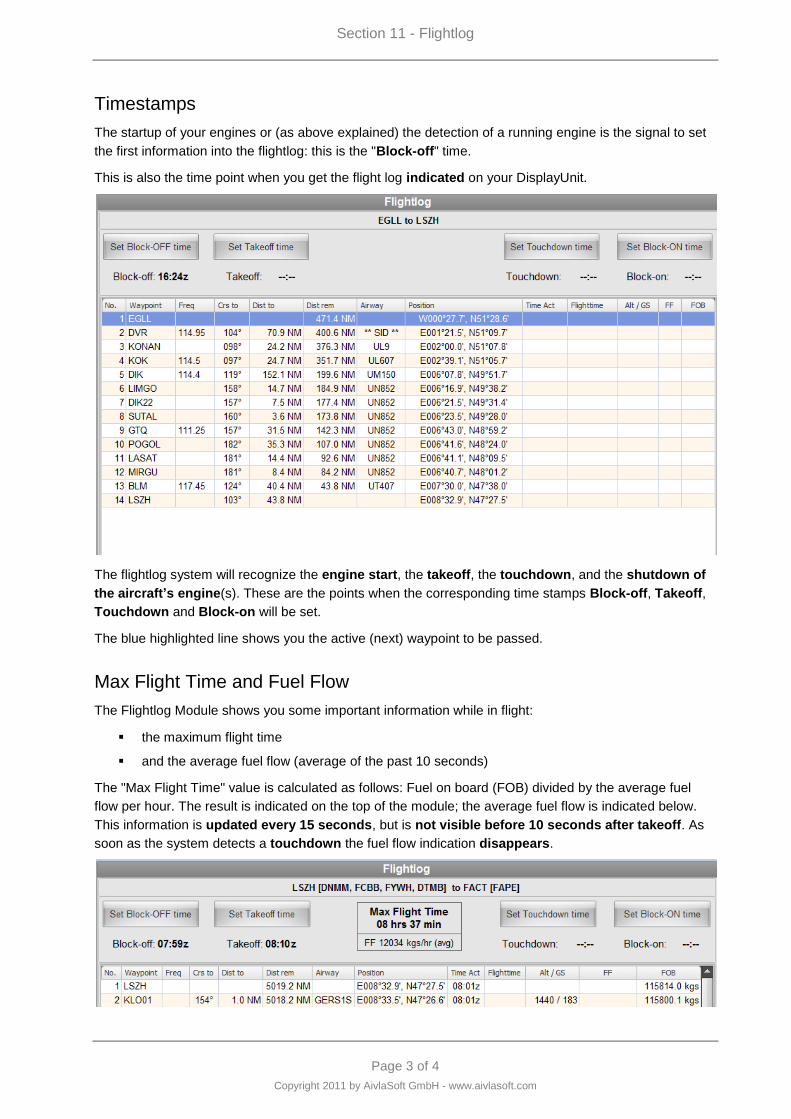
Section 11 - Flightlog
Page 3 of 4
Copyright 2011 by AivlaSoft GmbH - www.aivlasoft.com
Timestamps
The startup of your engines or (as above explained) the detection of a running engine is the signal to set
the first information into the flightlog: this is the "Block-off" time.
This is also the time point when you get the flight log indicated on your DisplayUnit.
The flightlog system will recognize the engine start, the takeoff, the touchdown, and the shutdown of
the aircraft‟s engine(s). These are the points when the corresponding time stamps Block-off, Takeoff,
Touchdown and Block-on will be set.
The blue highlighted line shows you the active (next) waypoint to be passed.
Max Flight Time and Fuel Flow
The Flightlog Module shows you some important information while in flight:
the maximum flight time
and the average fuel flow (average of the past 10 seconds)
The "Max Flight Time" value is calculated as follows: Fuel on board (FOB) divided by the average fuel
flow per hour. The result is indicated on the top of the module; the average fuel flow is indicated below.
This information is updated every 15 seconds, but is not visible before 10 seconds after takeoff. As
soon as the system detects a touchdown the fuel flow indication disappears.
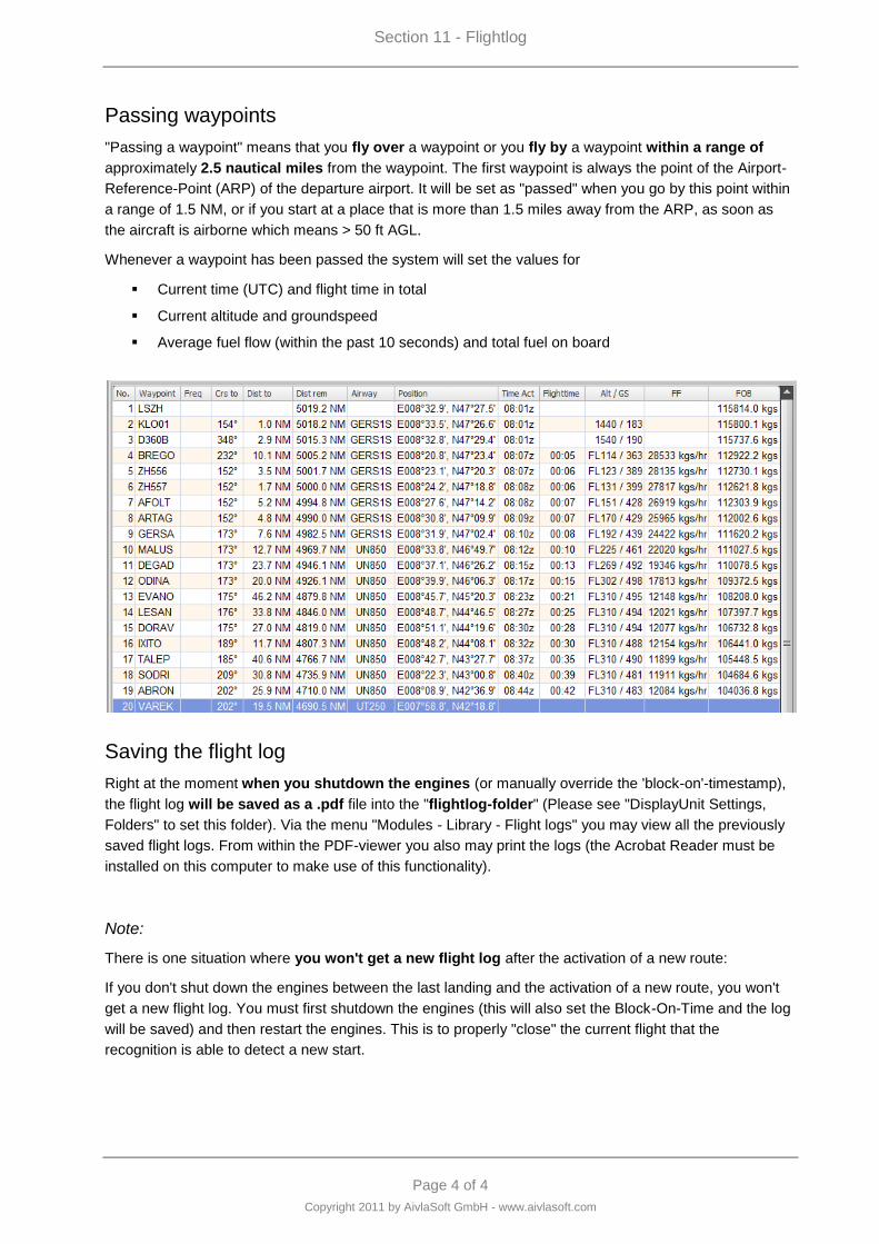
Section 11 - Flightlog
Page 4 of 4
Copyright 2011 by AivlaSoft GmbH - www.aivlasoft.com
Passing waypoints
"Passing a waypoint" means that you fly over a waypoint or you fly by a waypoint within a range of
approximately 2.5 nautical miles from the waypoint. The first waypoint is always the point of the Airport-
Reference-Point (ARP) of the departure airport. It will be set as "passed" when you go by this point within
a range of 1.5 NM, or if you start at a place that is more than 1.5 miles away from the ARP, as soon as
the aircraft is airborne which means > 50 ft AGL.
Whenever a waypoint has been passed the system will set the values for
Current time (UTC) and flight time in total
Current altitude and groundspeed
Average fuel flow (within the past 10 seconds) and total fuel on board
Saving the flight log
Right at the moment when you shutdown the engines (or manually override the 'block-on'-timestamp),
the flight log will be saved as a .pdf file into the "flightlog-folder" (Please see "DisplayUnit Settings,
Folders" to set this folder). Via the menu "Modules - Library - Flight logs" you may view all the previously
saved flight logs. From within the PDF-viewer you also may print the logs (the Acrobat Reader must be
installed on this computer to make use of this functionality).
Note:
There is one situation where you won't get a new flight log after the activation of a new route:
If you don't shut down the engines between the last landing and the activation of a new route, you won't
get a new flight log. You must first shutdown the engines (this will also set the Block-On-Time and the log
will be saved) and then restart the engines. This is to properly "close" the current flight that the
recognition is able to detect a new start.

Page 1 of 8
Copyright 2011 by AivlaSoft GmbH - www.aivlasoft.com
Section 12 - Checklists
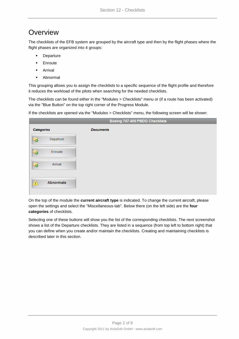
Section 12 - Checklists
Page 2 of 8
Copyright 2011 by AivlaSoft GmbH - www.aivlasoft.com
Overview
The checklists of the EFB system are grouped by the aircraft type and then by the flight phases where the
flight phases are organized into 4 groups:
Departure
Enroute
Arrival
Abnormal
This grouping allows you to assign the checklists to a specific sequence of the flight profile and therefore
it reduces the workload of the pilots when searching for the needed checklists.
The checklists can be found either in the "Modules > Checklists" menu or (if a route has been activated)
via the "Blue Button" on the top right corner of the Progress Module.
If the checklists are opened via the "Modules > Checklists" menu, the following screen will be shown:
On the top of the module the current aircraft type is indicated. To change the current aircraft, please
open the settings and select the "Miscellaneous-tab". Below there (on the left side) are the four
categories of checklists.
Selecting one of these buttons will show you the list of the corresponding checklists. The next screenshot
shows a list of the Departure checklists. They are listed in a sequence (from top left to bottom right) that
you can define when you create and/or maintain the checklists. Creating and maintaining checklists is
described later in this section.
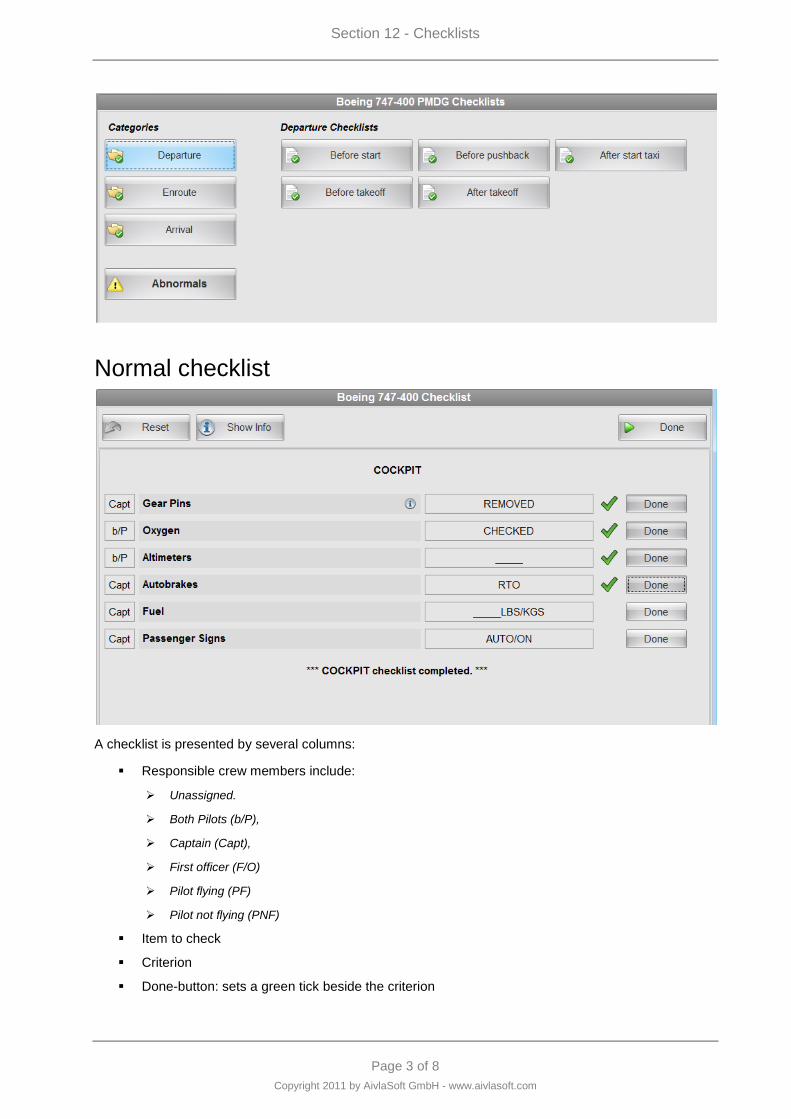
Section 12 - Checklists
Page 3 of 8
Copyright 2011 by AivlaSoft GmbH - www.aivlasoft.com
Normal checklist
A checklist is presented by several columns:
Responsible crew members include:
Unassigned.
Both Pilots (b/P),
Captain (Capt),
First officer (F/O)
Pilot flying (PF)
Pilot not flying (PNF)
Item to check
Criterion
Done-button: sets a green tick beside the criterion
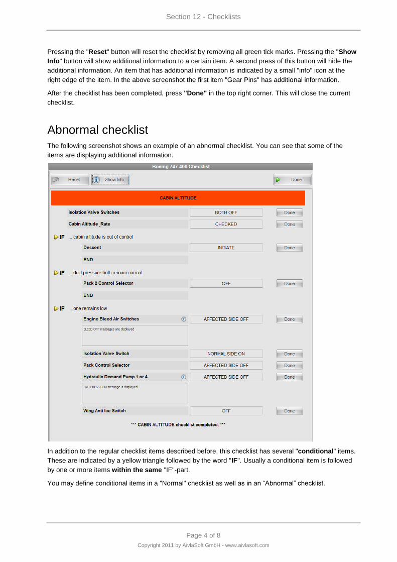
Section 12 - Checklists
Page 4 of 8
Copyright 2011 by AivlaSoft GmbH - www.aivlasoft.com
Pressing the "Reset" button will reset the checklist by removing all green tick marks. Pressing the "Show
Info" button will show additional information to a certain item. A second press of this button will hide the
additional information. An item that has additional information is indicated by a small "info" icon at the
right edge of the item. In the above screenshot the first item "Gear Pins" has additional information.
After the checklist has been completed, press "Done" in the top right corner. This will close the current
checklist.
Abnormal checklist
The following screenshot shows an example of an abnormal checklist. You can see that some of the
items are displaying additional information.
In addition to the regular checklist items described before, this checklist has several "conditional" items.
These are indicated by a yellow triangle followed by the word "IF". Usually a conditional item is followed
by one or more items within the same "IF"-part.
You may define conditional items in a "Normal" checklist as well as in an “Abnormal” checklist.
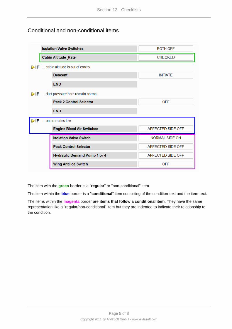
Section 12 - Checklists
Page 5 of 8
Copyright 2011 by AivlaSoft GmbH - www.aivlasoft.com
Conditional and non-conditional items
The item with the green border is a "regular" or "non-conditional" item.
The item within the blue border is a "conditional" item consisting of the condition-text and the item-text.
The items within the magenta border are items that follow a conditional item. They have the same
representation like a "regular/non-conditional" item but they are indented to indicate their relationship to
the condition.
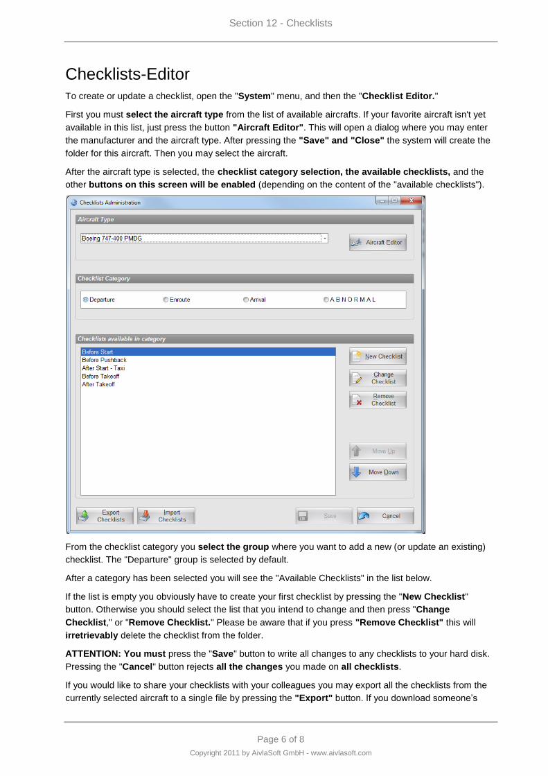
Section 12 - Checklists
Page 6 of 8
Copyright 2011 by AivlaSoft GmbH - www.aivlasoft.com
Checklists-Editor
To create or update a checklist, open the "System" menu, and then the "Checklist Editor."
First you must select the aircraft type from the list of available aircrafts. If your favorite aircraft isn't yet
available in this list, just press the button "Aircraft Editor". This will open a dialog where you may enter
the manufacturer and the aircraft type. After pressing the "Save" and "Close" the system will create the
folder for this aircraft. Then you may select the aircraft.
After the aircraft type is selected, the checklist category selection, the available checklists, and the
other buttons on this screen will be enabled (depending on the content of the "available checklists").
From the checklist category you select the group where you want to add a new (or update an existing)
checklist. The "Departure" group is selected by default.
After a category has been selected you will see the "Available Checklists" in the list below.
If the list is empty you obviously have to create your first checklist by pressing the "New Checklist"
button. Otherwise you should select the list that you intend to change and then press "Change
Checklist," or "Remove Checklist." Please be aware that if you press "Remove Checklist" this will
irretrievably delete the checklist from the folder.
ATTENTION: You must press the "Save" button to write all changes to any checklists to your hard disk.
Pressing the "Cancel" button rejects all the changes you made on all checklists.
If you would like to share your checklists with your colleagues you may export all the checklists from the
currently selected aircraft to a single file by pressing the "Export" button. If you download someone‟s

Section 12 - Checklists
Page 7 of 8
Copyright 2011 by AivlaSoft GmbH - www.aivlasoft.com
previously exported checklist and you would like to import it, press the "Import" button, then follow the
instructions presented by the dialog that follows. On the AivlaSoft Website (see Downloads) you will find
checklists that are free to use with many popular aircraft.
The sequence of the checklists in "Available Checklists" will also be the sequence within the
corresponding menu. You may change the sequence of the menus by selecting the menu and then
pressing the "Move up" or "Move down" button.
By the way: It is highly recommended to save the aircrafts folder by integrating it in your daily backup
procedure. Even better is to integrate the whole "UserData" folder in your daily backup procedure.
Don't you save your data regularly?
Creating or changing a checklist
To show you all the possibilities when creating a checklist, just have a look on the following screenshot
which shows you the abnormal checklist "Cabin altitude" from a Boeing 747-400.
Before pressing the "Change item" button or the "Remove Item" button you must select an item from the
list.
If you want to add a new item, press "New Item". A new item will always be added at the end of the list.
You may use the buttons "Move Up" and "Move Down" to change the position of an item within the list.

Section 12 - Checklists
Page 8 of 8
Copyright 2011 by AivlaSoft GmbH - www.aivlasoft.com
Every item in a checklist can be defined as follows:
Select whether or not this is a conditional item. Depending on your selection the text box to enter the
condition will be enabled or disabled.
Select whether the item follows a conditional item. It cannot be both (condition and following a
condition).
Select the crewmember that has the responsibility to carry out the item.
Enter the item text and also the criterion text.
If needed, enter additional text as information for this item.
Press "OK" to save the item in the current checklist.
Press "Cancel" to reject the changes.

Page 1 of 4
Copyright 2011 by AivlaSoft GmbH - www.aivlasoft.com
Section 13 - Library
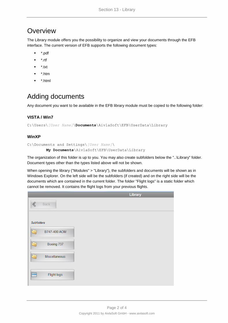
Section 13 - Library
Page 2 of 4
Copyright 2011 by AivlaSoft GmbH - www.aivlasoft.com
Overview
The Library module offers you the possibility to organize and view your documents through the EFB
interface. The current version of EFB supports the following document types:
*.rtf
*.txt
*.htm
*.html
Adding documents
Any document you want to be available in the EFB library module must be copied to the following folder:
VISTA / Win7
C:\Users\[User Name]\Documents\AivlaSoft\EFB\UserData\Library
WinXP
C:\Documents and Settings\[User Name]\
My Documents\AivlaSoft\EFB\UserData\Library
The organization of this folder is up to you. You may also create subfolders below the "..\Library" folder.
Document types other than the types listed above will not be shown.
When opening the library ("Modules" > "Library"), the subfolders and documents will be shown as in
Windows Explorer. On the left side will be the subfolders (if created) and on the right side will be the
documents which are contained in the current folder. The folder "Flight logs" is a static folder which
cannot be removed. It contains the flight logs from your previous flights.
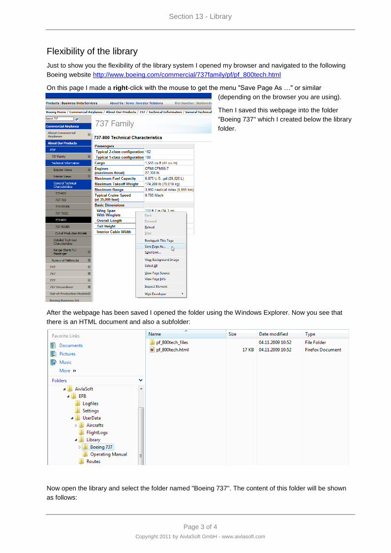
Section 13 - Library
Page 3 of 4
Copyright 2011 by AivlaSoft GmbH - www.aivlasoft.com
Flexibility of the library
Just to show you the flexibility of the library system I opened my browser and navigated to the following
Boeing website http://www.boeing.com/commercial/737family/pf/pf_800tech.html
On this page I made a right-click with the mouse to get the menu "Save Page As …" or similar
(depending on the browser you are using).
Then I saved this webpage into the folder
"Boeing 737" which I created below the library
folder.
After the webpage has been saved I opened the folder using the Windows Explorer. Now you see that
there is an HTML document and also a subfolder:
Now open the library and select the folder named "Boeing 737". The content of this folder will be shown
as follows:
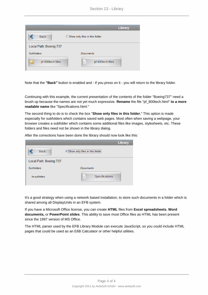
Section 13 - Library
Page 4 of 4
Copyright 2011 by AivlaSoft GmbH - www.aivlasoft.com
Note that the "Back" button is enabled and - if you press on it - you will return to the library folder.
Continuing with this example, the current presentation of the contents of the folder "Boeing737" need a
brush up because the names are not yet much expressive. Rename the file "pf_800tech.html" to a more
readable name like "Specifications.html."
The second thing to do is to check the box "Show only files in this folder." This option is made
especially for subfolders which contains saved web pages. Most often when saving a webpage, your
browser creates a subfolder which contains some additional files like images, stylesheets, etc. These
folders and files need not be shown in the library dialog.
After the corrections have been done the library should now look like this:
It's a good strategy when using a network based installation, to store such documents in a folder which is
shared among all DisplayUnits in an EFB system.
If you have a Microsoft Office license, you can create HTML files from Excel spreadsheets, Word
documents, or PowerPoint slides. This ability to save most Office files as HTML has been present
since the 1997 version of MS Office.
The HTML parser used by the EFB Library Module can execute JavaScript, so you could include HTML
pages that could be used as an E6B Calculator or other helpful utilities.