Embed Size (px)
Citation preview
Australian Journal of Basic and Applied Sciences, 6(6): 99-110, 2012 ISSN 1991-8178
Corresponding Author: Jurifa Mat Lazi, Department of Power Electronics and Drives, Faculty of Electrical Engineering, Universiti Teknikal Malaysia Melaka, Hang Tuah Jaya, 76100 Durian Tunggal, Melaka, Malaysia
E-mail: [email protected] Tel : +60193844707
99
Sensorless Speed Control of Independent Dual-PMSM Drives Fed by a Five-Leg Inverter
Jurifa Mat Lazi, Zulkifilie Ibrahim, Mariana Yusoff, Siti Noormiza Mat Isa, Nurazlin Mohd Yaakop,
Ahmad Shukri Abu Hasim
Department of Power Electronics and Drives, Faculty of Electrical Engineering, Universiti Teknikal Malaysia Melaka, Hang Tuah Jaya, 76100 Durian Tunggal, Melaka, Malaysia
Abstract: Various control algorithms have been investigated for speed sensorless of an AC motors using three-leg inverter by other researchers. Unfortunately, these sensorless techniques are mainly focus on single motor controlled drive with a single three-le inverter. Resent research has shown that the dual-motor drives can be independently controlled by using a Five-Leg Inverter (FLI). This paper introduces the new control strategy based on speed sensorless technique of independent dual- Permanent Magnet Synchronous Motor (PMSM) drives using FLI. The simulation is implemented in MATLAB/Simulink to evaluate the overall motor drive performance. The transient behavior is examined for various speed commands, load disturbance, inertia and during zero speed operation, so that a thorough comparison is enable. The simulation results also proved that the performance characteristics of sensorless dual-PMSM are almost similar to the sensory system except for the start-up condition. For future research, there is a need to emphasize on the start-up method for sensorless dual-PMSM drives. Key words: Sensorless, Dual PMSMs, Five-Leg Inverter, SVPWM.
INTRODUCTION
Dual-Motor drives using Five-Leg Inverter (FLI) is designed to provide an individually control for the dual-motor drives which can be controlled independently for different types of operating condition. FLI topology consists of ten switches, where one of the legs is commonly shared by the Dual PMSMs as illustrated in Fig. 2. It also proven that dual-motor can be operated independently at different operating condition by using FLI topology (Vukosavic et al., 2008, Oka et al., 2006, Jones et al., 2008b, Jacobina et al., 2008, Delarue et al., 2003a). Independent control for dual-motor fed by FLI was introduced by Francois and Bouscayrol in 1999 (Francois and Bouscayrol, 1999). The idea of FLI was proven can be used to control for different rotations speeds on both motors. In addition, they try to extend the capability of the FLI in AC-AC converter in order to supply a single IM with unitary power factor (Francois et al., 2000). However, those researches are only present in simulation results only. Only in 2003, they come out with the experimental prove that FLI topology is able to control dual-motor for different applications (Delarue et al., 2003a). Since then, many researchers are giving attentions to this topology and came out with different strategies (Bouscayrol et al., 2005, Delarue et al., 2003a, Delarue et al., 2003b, Francois and Bouscayrol, 1999, Francois et al., 2000, Jacobina et al., 2008, Jones et al., 2008a, Jones et al., 2008b, Jones et al., 2009, Ledezma et al., 2001, Oka et al., 2006, Vukosavic et al., 2008). Different types of Pulse Width Modulation (PWM) method are investigated by Jones (Jones et al., 2008a). This paper simulates four PWM methods for FLI for the purpose of Dual-Motor drives namely Dual Voltage Modulation (DVM), Modulation Block Method (MBM), Inversion Table Method (IVM) and Double Zero-Sequence Injection Method (DZS). These modulation methods are compared in terms of theory, configuration, total harmonic distortion and switching state. As the conclusion, DZS is the most appropriate method due to arbitrary distribution of the available constant switching frequency in all five inverter legs. Other than that (Jones et al., 2008b) propose new DZS for PWM strategy. They provide the simulation and experimental results for carrier based PWM and Space Vector Pulse Width Modulation (SVPWM). DSZ in this reference utilizes standard three-phase modulators to generate modulation signals for all legs of a five-leg VSI. The solution enables any portion of the DC bus voltage to be allocated to any of the two machines. This method is the simplest method to be implemented using standard microprocessors. It produces a symmetrical switching pattern, with identical switching frequency in all five inverter legs. Furthermore all 32 available inverter switching states are utilized. The only drawback of this method is the combine voltage required by the two motors cannot exceed the available DC bus voltage which is considered as rated for one three-phase motor.
Aust. J. Basic & Appl. Sci., 6(6): 99-110, 2012
100
Expanded Two-Arm Modulation (ETAM) technique was introduced by (Kimura et al., 2005). This technique is proven that can improve the voltage utility factor (UVF) from 50% to 86%. However, only simulation results are presented. After that, (Oka et al., 2006) propose new scheme based on ETAM. This new scheme is proven the mathematical theory and simulation results. However, it is only applicable for same frequency operation. (Ohama et al., 2009) came out with the experimental results for ETAM technique. Based on the literature, this current study utilized Space Vector Pulse Width Modulation (SVPWM) method (Vukosavic et al., 2008), since this is the simplest and easiest method to implement using single processor. Other than that, this technique utilizes standard three-phase modulators to generate modulation signals for all legs of a FLI. The modulation technique that is being used in this current study is depicted in Fig. 2. In the case of conventional Five-Leg Inverter (FLI), a lot of external wires, sensors are needed because it deals with the two sets of current sensors, two sets of encoders or resolvers in order to capture the information of rotor position. The appearance of all the transducers increases the total size and costs of the drives. Because of these problems, this current study proposes the sensorless technique for dual-PMSM drive using FLI in order to reduce the drive space and to lower overall cost by eliminating the mechanical position sensor. Nevertheless, the performance of this sensorless technique are almost similar to the drive that using sensor. Various techniques in sensorless strategy are discussed by different researchers. Most of the techniques are based on the voltage equations of the PMSM and the information of the terminal quantities, such as line voltage and phase current. By using this information, the rotor angle and speed are estimated directly or indirectly. Basically, estimation of the sensorless techniques can be based on different categories; Back Electromagnetic Force, Excitation Monitoring, Motor Modification, Magnetic Saliency, Observer and Signal injection. The direct back EMF detection method uses measurements of the instantaneous voltage across the non-conducting phase. If the drive is designed such that the non-conducting phase current reduces rapidly, then the back EMF can be measured directly across the non-conducting phase. The zero crossing of the phase voltage can then be used to generate commutation data. Detail explanation about principle of this approach is described in (Iizuka et al., 1985) and (Genduso et al., 2010). Back EMF estimation for the rotor speed offers satisfactory performance at higher speed. This method requires simple algorithm and uses less computational time. However, the main drawback of this method is the inaccuracies results at low speed. It is because the back-emf values approaches zero during low speed time interval (Maiti et al., 2009). The amplitude of the back EMF is proportional to speed. During the zero speed condition, the magnets do not induce any voltage. Additionally, the voltage and current signals are quite noisy because of the Pulse Width Modulation (PWM) operation on the power module. In the low-speed range, the voltage on the motor terminal is barely be detected because the value of the back-EMF of the motor is very small and also because of the noise that exist in the system. Excitation monitoring schemes involve monitoring the conduction paths of the current through the inverter. One method is to monitor the conduction state of the inverter’s anti-parallel free-wheeling diodes (Ogasawara and Akagi, 1991). The system operates by chopping one switching signal and leaving the other devices on continuously. The back EMF voltage of the non-switching phase is then measured and when this voltage crosses zero, a commutation position is detected. This method also requires of extra hardware implementation due to the purpose of signal injection. However the main attraction of this method is it is very reliable at zero speed. This method can be tested by either using voltage space phasor or using current space phasor (De Belie et al., 2010). Observer-based systems allow the controller to access states which are not directly measurable. For example, flux linkage is not a directly measurable quantity. So, to obtain the flux linkage, the motor’s phase voltages and currents are measured. These, can be used together with the phase resistance, to obtain an estimation of flux-linkage via integration. (Wu and Slemon, 1991) applied this technique to a surface mounted PMSM, where EMF is estimated from the measurement of terminal voltages and stator currents and is then processed to produce the stator flux linkage space vector. The angle of this vector is used to produce the stator current command signals. The system also uses the rate of change of the flux linkage angle to obtain a speed signal. Another class of observers uses the Extended Kalman Filter (EKF) to estimate both position and speed in real time (Eskola and Tuusa, 2003). The main drawback of this method is the requirement of extra hardwire and need of huge memory, thus it need appropriate processor because of it deals with high sampling frequencies. Another method (Elbuluk et al., 2002, Maiti et al., 2008, Rajasekhar et al., 2011) is using model references adaptive control (MRAC). MRAC computes a desired state (called as the functional candidate) using two different models (i.e. reference and adjustable models). The error between the two models is used to estimate an unknown parameter. Hence, there is many more speed estimation techniques have been reported in literature such as Back-EMF based method, Artificial Intelligent (AI), State observer based method and etc. Design of Sensorless Speed Control for Dual-Pmsm: This current study introduces a sensorless technique using adaptive control based on differential of d-q currents and voltages to estimate the speed of motors “A” and “B”. The basic diagram for overall block diagram is depicted in Fig.1. This figure shows the overall block diagram of the proposed method which consist of two sets of PMSM drive, single FLI, speed controller and the speed and position estimator for each motor. The

Aust. J. Basic & Appl. Sci., 6(6): 99-110, 2012
101
output of three-phase voltages and currents for both motors are measured. These currents and voltages are being used in the speed estimator. The estimator will produce the estimated value of motor’s speed. The estimated rotor position is calculated by integrating the value of the motor speed.
Motor“B”
PI speed controller Motor
“A”Five- Leg Inverter(FLI)
A
B
0dAi
0dBi
qAi
qBi
qAvPI current
controller
PI current controller
dAv
qBv
dBv
PI current controller
PI current controller
PI speed controller
Speed and
Position Estimator
abc
DQ
abc
Park clark
DQ
cAbAaA vvv ,,
cBbBaB vvv ,,
cBbBaB iii ,,
cAbAaA iii ,,
.)( estB
.)(estB
.)(estA
.)(estA
BA ,
BA ,
Fig. 1: Block Diagram of the proposed method Five-Leg Inverter For Dual-Pmsm: Five-Leg Inverter (FLI) consists of ten switches, which one of the leg is commonly shared by Dual PMSMs as depicted in Fig. 2. Two PMSMs share the inverter leg 3 that connected to phase cA and cB. While legs 1 and 2 are connected to phases aA and bA respectively of the motor “A”. Inverter legs 4 and 5 are connected to phases aB and bB, respectively of the motor “B”. Voltage of DC link (Vdc) is considered as rated voltage for operating range of one machine can be achieved (Jones et al., 2008b). FLI topology offers saving of two switches when compared to the standard dual-three-phase voltage source inverter configuration. Thus, it can reduce the complexity of the inverter structure and also possibility to control dual three-phase motors using only single processor.
AvBv
CvDv
Ev
DCv
Aa
Ab
BbBa
Ac
Bc
Fig. 2: Dual-PMSM fed by Five Leg Inverter (FLI). Modulation Technique: Different modulation techniques are applied throughout the literature (Delarue et al., 2003a, Delarue et al., 2003b, Jones et al., 2008a, Jones et al., 2008b, Oka et al., 2006, Vukosavic et al., 2008). This current study is using Space Vector Pulse Width Modulation (SVPWM) method that is being used in (Vukosavic et al., 2008), since this is the simplest method and very easy to implement using single processor. Other than that, this method utilizes standard three-phase modulators to generate modulation signals for all legs of a FLI.

Aust. J. Basic & Appl. Sci., 6(6): 99-110, 2012
102
Fig. 3: Space Vector Pulse Width Modulation for FLI, Dual-Motor drives. Fig. 3 shows the configuration of dual SVPWMs for FLI, Dual Motor drives. The output for SVPWM is arranged in that particular way in order to reduce the number of modulating signal from six to five. The output of five modulating signals for inverter legs are explained below:
cAbBE
cAaBD
cBcAC
cBbAB
cBaAA
(1)
Where subscripts “A” and “B” represent motor “A” and motor “B” respectively. From equation
(1), the signal of cB is added to the modulating signals coming from the motor “A” PWM modulator. This
signal has no effect on the voltages of the motor “A” since it appears as a zero-sequence component and it gets
cancelled in the line-to-line voltages of motor “A”. This sequence is similar to signal cA , which is added to the
output of motor “B” modulator. It does not affect any operation motor “B”. Let say the switching period, ts is equal to “1”. The value of the duty cycles for each space vector modulator is between “0” and “1”. When the reference input is equal to zero, the resulting duty cycle is about 0.5. By referring to equation (1), the summation duty cycle between motor “A” and motor “B” will be shifted between the ranges 0.5 to 1.5. These new range is not fit for the switching period value. Therefore, 0.5 need to be withdrawn from the equation (1) as shown in Fig.3. Application time for zero space vector “III” is increasing effectively while the application time for zero space vector “000” is decreasing before shifted to “-0.5” without affecting to application time for two active space vectors. This chronology is similar to motor “B” by referring to equation (1).
refAv ,
I
II
III
IV
V
VI
100
110010
011
001 101
refBv ,I
II
III
IV
V
VI
100
110010
011
001 101 (a) (b)

Aust. J. Basic & Appl. Sci., 6(6): 99-110, 2012
103
aAm
bAm
cAm
st
aAbAcA
0
0
0 0
0
0 0 0 0
00
0
1 1
1
1
1
1 11 1
aBm
bBm
cBm
st
bB
cB
aB
0
0
0 0
0 0 0
0 0
0
0 0
1 1
1
1
1
1
1 1
1
(c) (d)
1
st
0
0
0
0
0
0
0
0
0
0
0
A
B
C
DE
Am
Bm
Cm
Dm
Em
1
1
11 1
1 1
1
1
1
1111
1
1
1
1
1111 1 1
00 0
0
00
00
000000 0
0 0 0 0
(e) Fig. 2: Space Vector PWM (SVPWM) and the switching pattern for the FLI; a)Space Vector reference for
motor “A”, b) Space Vector reference for motor “B”, c) Switching pattern for motor “A”, d) Switching pattern for motor “B”, e) Switching pattern for the Five-Leg Inverter (FLI)
Fig. 2 show the space vector modulator operation, which Fig. 2(a) and (b) present the reference space
vectors with 0, 453.0 VdcV refA for motor “A” located in sector I, and 0
, 1402.0 VdcV refB for motor
“B” located in sector II respectively. The dashed boxes represent the time duration and the active space vectors for both motors “A” and “B” in Fig. 2(c) and (d). Meanwhile Fig. 2(e) shows the resulted combined SVPWM switching pattern for FLI. It is proven that total zero vector time durations for motor “A” and “B” are still similar as for individually SVPWM. Thus, the identical space vectors of each motor are completed each other and the space vector modulator is able to fulfil the requirements of the both motors. It also can be seen that, at the remaining next part which space vectors reference of each motor are contradicting, and the requirements of one motor are met, the second machine will receive zero space vector (000 or III). This shows that all of 32 switching states for FLI are utilised and there are no limit to use all the available states. The resultant PWM signal is symmetrical and this makes FLI topology can be implemented using single standard microprocessor. Mathematical Model For Dual Pmsms Drives: The mathematical model for PMSM “A” in d-q reference frame can be determined by following equations (Rajasekhar et al., 2011),(Pillay and Krishnan, 1989).
qAedAdAsAdA dt
dirv (2)
dAeqAqAsAqA pirv (3)
Aust. J. Basic & Appl. Sci., 6(6): 99-110, 2012
104
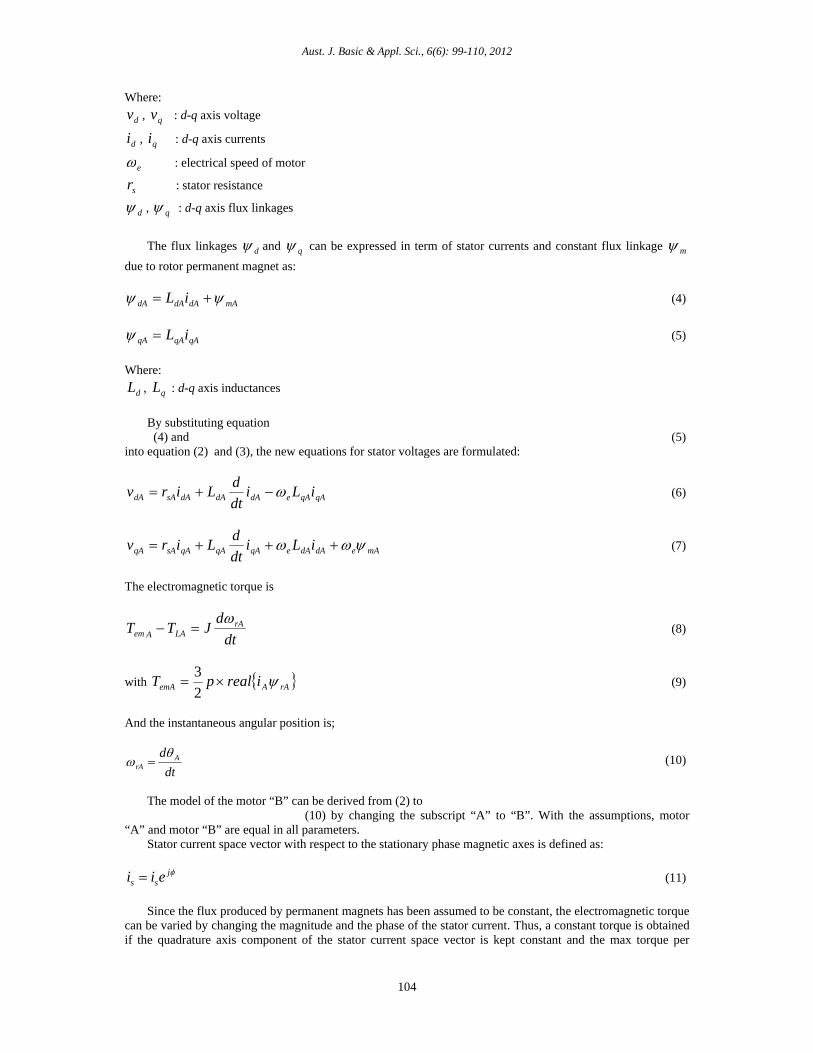
Where:
dv , qv : d-q axis voltage
di , qi : d-q axis currents
e : electrical speed of motor
sr : stator resistance
d , q : d-q axis flux linkages
The flux linkages d and q can be expressed in term of stator currents and constant flux linkage m
due to rotor permanent magnet as:
mAdAdAdA iL (4)
qAqAqA iL (5)
Where:
dL , qL : d-q axis inductances
By substituting equation (4) and (5) into equation (2) and (3), the new equations for stator voltages are formulated:
qAqAedAdAdAsAdA iLidt
dLirv (6)
mAedAdAeqAqAqAsAqA iLidt
dLirv (7)
The electromagnetic torque is
dt
dJTT rA
LAAem
(8)
with rAAemA irealpT 2
3 (9)
And the instantaneous angular position is;
dt
d ArA
(10)
The model of the motor “B” can be derived from (2) to (10) by changing the subscript “A” to “B”. With the assumptions, motor “A” and motor “B” are equal in all parameters. Stator current space vector with respect to the stationary phase magnetic axes is defined as:
jss eii (11)
Since the flux produced by permanent magnets has been assumed to be constant, the electromagnetic torque can be varied by changing the magnitude and the phase of the stator current. Thus, a constant torque is obtained if the quadrature axis component of the stator current space vector is kept constant and the max torque per

Aust. J. Basic & Appl. Sci., 6(6): 99-110, 2012
105
Ampere of stator current is obtained if the torque angle is 900. This corresponds to the application of imaginary axis only for the above stator current equation. Design of Speed And Position Estimator: Fig. 3 represents the configuration of speed and position estimation scheme(Rajasekhar et al., 2011). It consists of three-phase to two-phase conversion, adjustable model and adaptation mechanism. The goals in the design are reducing the noise impact to control and influence the system transient response as small as possible.
Fig. 3: Configuration of speed and position estimator for motor “A” and “B”. Firstly, the three-phase voltage and current are converted to d-q model. Then,the d-q currents and voltages are being used in Adjustable Model and Adaptation Mechanism respectively. From equation (6) and (7), the Adjustable Model equations can be formulated as below:
dqqedsdd LiLirvidt
d/)( (12)
qmeddeqsqq LiLirvidt
d/)( (13)
The output of conversion three phase model is estimated d-q current which is compared with actual d-q axis currents. These currents are used to calculate the estimated speed through adaptation mechanism. The adaptation mechanism is designed in order to improve the stability and behavior of the adaptive system. It is calculated using Popov’s hyper-stability theory to derive the estimated speed as in equation (14)
s
kk i
pest
(14)
estqqm
estdqestqd iiL
iiii
(15)
An estimation error defined by equation (15) is derived when the speed used in the current model is not identical to the actual one without any influence of parameter variation. A tuning signal for the adjustable model is generated from the regulation of this error through a PI controller. Simulation Results: The proposed speed estimation algorithm for dual-PMSM drive has been simulated in MATLAB/SIMULINK under following operating conditions. The motor parameters are presented in Table 1 for convenience.
Aust. J. Basic & Appl. Sci., 6(6): 99-110, 2012
106
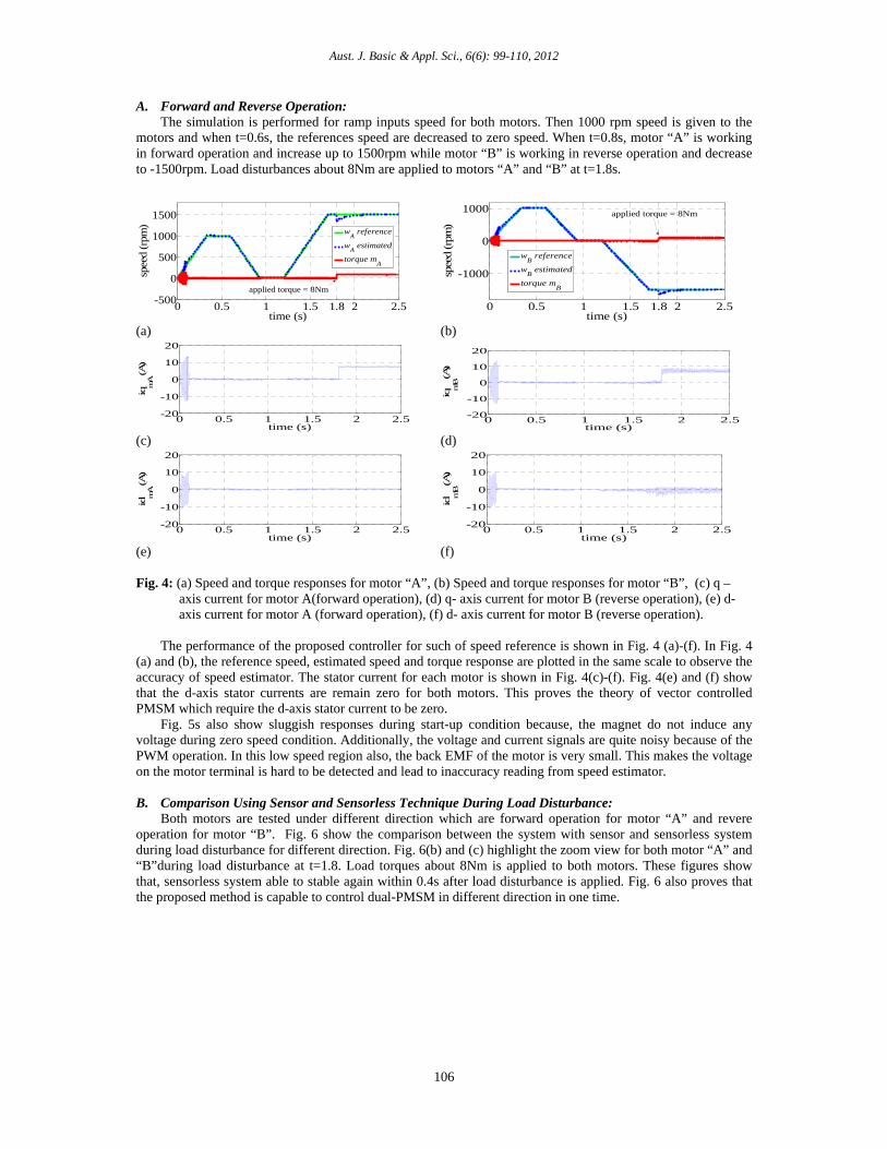
A. Forward and Reverse Operation: The simulation is performed for ramp inputs speed for both motors. Then 1000 rpm speed is given to the motors and when t=0.6s, the references speed are decreased to zero speed. When t=0.8s, motor “A” is working in forward operation and increase up to 1500rpm while motor “B” is working in reverse operation and decrease to -1500rpm. Load disturbances about 8Nm are applied to motors “A” and “B” at t=1.8s.
0 0.5 1 1.5 1.8 2 2.5-500
0
500
1000
1500
time (s)
spee
d (r
pm)
wA
reference
wA
estimated
torque mA
applied torque = 8Nm
0 0.5 1 1.5 1.8 2 2.5
-1000
0
1000
time (s)
spee
d (r
pm)
wB reference
wB estimated
torque mB
applied torque = 8Nm
(a) (b)
0 0.5 1 1.5 2 2.5-20
-10
0
10
20
time (s)
iqmA (A)
0 0.5 1 1.5 2 2.5
-20
-10
0
10
20
time (s)
iqmB (A)
(c) (d)
0 0.5 1 1.5 2 2.5-20
-10
0
10
20
time (s)
idm
A (A)
0 0.5 1 1.5 2 2.5
-20
-10
0
10
20
time (s)
idmB (A)
(e) (f) Fig. 4: (a) Speed and torque responses for motor “A”, (b) Speed and torque responses for motor “B”, (c) q –
axis current for motor A(forward operation), (d) q- axis current for motor B (reverse operation), (e) d- axis current for motor A (forward operation), (f) d- axis current for motor B (reverse operation).
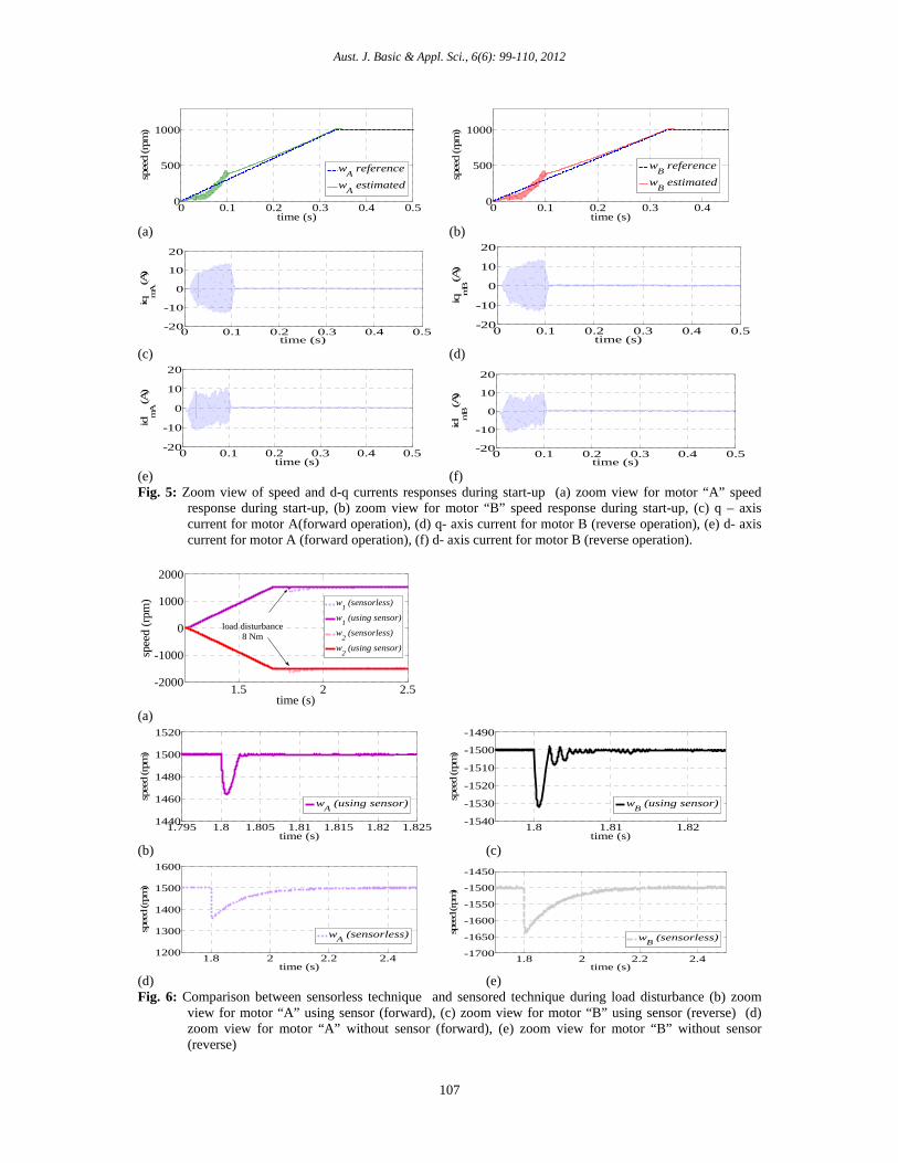
The performance of the proposed controller for such of speed reference is shown in Fig. 4 (a)-(f). In Fig. 4 (a) and (b), the reference speed, estimated speed and torque response are plotted in the same scale to observe the accuracy of speed estimator. The stator current for each motor is shown in Fig. 4(c)-(f). Fig. 4(e) and (f) show that the d-axis stator currents are remain zero for both motors. This proves the theory of vector controlled PMSM which require the d-axis stator current to be zero. Fig. 5s also show sluggish responses during start-up condition because, the magnet do not induce any voltage during zero speed condition. Additionally, the voltage and current signals are quite noisy because of the PWM operation. In this low speed region also, the back EMF of the motor is very small. This makes the voltage on the motor terminal is hard to be detected and lead to inaccuracy reading from speed estimator. B. Comparison Using Sensor and Sensorless Technique During Load Disturbance: Both motors are tested under different direction which are forward operation for motor “A” and revere operation for motor “B”. Fig. 6 show the comparison between the system with sensor and sensorless system during load disturbance for different direction. Fig. 6(b) and (c) highlight the zoom view for both motor “A” and “B”during load disturbance at t=1.8. Load torques about 8Nm is applied to both motors. These figures show that, sensorless system able to stable again within 0.4s after load disturbance is applied. Fig. 6 also proves that the proposed method is capable to control dual-PMSM in different direction in one time.
Aust. J. Basic & Appl. Sci., 6(6): 99-110, 2012
107
0 0.1 0.2 0.3 0.4 0.50
500
1000
time (s)
spee
d (r
pm)
wA reference
wA estimated
0 0.1 0.2 0.3 0.4
0
500
1000
time (s)
spee
d (r
pm)
wB reference
wB estimated
(a) (b)
0 0.1 0.2 0.3 0.4 0.5-20
-10
0
10
20
time (s)
iqmA (A)
0 0.1 0.2 0.3 0.4 0.5
-20
-10
0
10
20
time (s)
iqm
B (A)
(c) (d)
0 0.1 0.2 0.3 0.4 0.5-20
-10
0
10
20
time (s)
idm
A (A)
0 0.1 0.2 0.3 0.4 0.5
-20
-10
0
10
20
time (s)id
mB (A)
(e) (f) Fig. 5: Zoom view of speed and d-q currents responses during start-up (a) zoom view for motor “A” speed
response during start-up, (b) zoom view for motor “B” speed response during start-up, (c) q – axis current for motor A(forward operation), (d) q- axis current for motor B (reverse operation), (e) d- axis current for motor A (forward operation), (f) d- axis current for motor B (reverse operation).
1.5 2 2.5-2000
-1000
0
1000
2000
time (s)
spee
d (r
pm)
w1 (sensorless)
w1 (using sensor)
w2 (sensorless)
w2 (using sensor)
load disturbance8 Nm
(a)
1.795 1.8 1.805 1.81 1.815 1.82 1.8251440
1460
1480
1500
1520
time (s)
spee
d (r
pm)
wA (using sensor)
1.8 1.81 1.82-1540
-1530
-1520
-1510
-1500
-1490
time (s)
spee
d (r
pm)
wB (using sensor)
(b) (c)
1.8 2 2.2 2.41200
1300
1400
1500
1600
time (s)
spee
d (rpm
)
wA (sensorless)
1.8 2 2.2 2.4-1700
-1650
-1600
-1550
-1500
-1450
time (s)
spee
d (rpm
)
wB (sensorless)
(d) (e) Fig. 6: Comparison between sensorless technique and sensored technique during load disturbance (b) zoom
view for motor “A” using sensor (forward), (c) zoom view for motor “B” using sensor (reverse) (d) zoom view for motor “A” without sensor (forward), (e) zoom view for motor “B” without sensor (reverse)

Aust. J. Basic & Appl. Sci., 6(6): 99-110, 2012
108
020406080
100120140160
0 2 4 6 8 10
Un
ders
hoo
t (r
pm)
Load Torque (Nm)
Undershoot(reverse)-sensorless
Undershoot(forward)-sensorless
Undershoot (forward)-sensored
Undershoot (reverse) -sensored
Fig. 7: Undershoot during load disturbance for system with sensor and sensorless system. Fig. 7 presents the undershoot characteristic for both motor “A” and “B” during load disturbance either with sensor or without sensor. It is clearly shown that both sensor and sensorless techniques are having undershot when load is applied. This characteristics promise that the behavior of the sensorless system is almost similar with the system that using sensor even though the responses are not fast as that system. C. Zero Speed Operation: Fig. 8 illustrates the estimated speed responses for both motor “A” and “B” during zero speed operation. The proposed sensorless speed controlled in this current study does not have any integrator problems, makes the zero speed operation is possible to achieve. It noticed that motor “A” is at standstill during 0.9s to 1.2s and motor “B” at 0.8s until 1.2s. Both motors are maintained at 800rpm and 400rpm before the zero speed operation. This behavior gives similar results for single motor as reported in [25], but this result in Fig. 8 Fig. 8 is for dual-motor. The motors are tested again with this behavior for three times to show the reliability of
the proposed controller.
0 1 2 3
0
250
500
750
1,000
time (s)
spee
d (r
pm)
Motor A
Motor B
Fig. 8: Speed responses for motor “A” and “B” during zero speed operation. D. Variation of Load and Speed: Fig. 9 (a) represent the actual speed responses for motor “A” at 2000rpm. At t=0.8s, variation of load disturbances from 25% of rated torque (2Nm) until 125% of rated torque (10Nm) are applied to the motor “A” while Motor “B” which is running at 500rpm hold the constant 8Nm torque. This figures shows that, the system is stble for wide range of rated torque. Fig. 9Fig. 9 (b) represents the actual speed responses of motor “B” with different speed command having load disturbance at rated torque, and motor “A” at 10 rpm. Motor “B” is tested at different speed from 500rpm (25% of rated speed) until 2000rpm. E. Different Inertia: In order to verify the robustness of the drive system, the sensitivity of the speed response to motor inertia need to be concerned. All the previous test are done by applying rated inertia which is J=0.0006329kgm2 .
Another 4 tests incorporating different inertia which are 0.8J, 0.5J, 1.2J and 1.5J are conducted during load disturbance about 8Nm to observe the effect of the different inertia to the drive system.

Aust. J. Basic & Appl. Sci., 6(6): 99-110, 2012
109
Fig. 10s show the insensitivity of the proposed technique to inertia variations and consistency of speed responses are obtained by all value of J.
0.7 0.8 0.9 1 1.1 1.21800
1850
1900
1950
2000
2050
time (s)
spee
d (r
pm)
ref. speed
TLA
=2nm
TLA
=4nm
TLA
=6nm
TLA
=8nm
TLA
=10nm
0 0.5 1 1.5
0
500
1000
1500
2000
time (s)
spee
d (r
pm)
motor Bspeed varies
motor A (10 rpm)
load disturbance =8Nm
(a) (b) Fig. 9: Speed respons (a) actual speed response for motor “A” under variation of load disturbance (zoom view)
(b) Actual speed responses of motor “B” with different speed command having load disturbance at rated torque , and motor “A” at 10 rpm.
1.8 1.802 1.804 1.806 1.808 1.811350
1400
1450
1500
time (s)
spee
d (r
pm)
1.5J0.8J
0.5J
J1.2J
1.8 1.802 1.804 1.806 1.808 1.81
-1650
-1600
-1550
-1500
time (s)
spee
d (r
pm)
J1.2J
1.5J0.8J
0.5J
(a) (b) Fig. 10: Speed responses during load disturbance about 8Nm for different inertia (a) for motor “A” (forward
operation) and (b) for motor “B” (reverse operation). Table 1: Specifications of Motors “A” And Motor “B”.
No Motor Specifications Value 1 Rated Torque 8Nm 2 Rated Speed 209rad/s 3 Inertia 0.0006329 kgm2
4 Resistance 0.9585 5 Inductance 0.00525 H 6 Magnet Flux 0.1827 Vs 7 DC Link Voltage 300 V
Conclusion: This paper presents results of an extensive comparative simulation study related to sensorless and conventional speed sensory control for identical dual-PMSM fed by a single FLI. Simulation study is done using the same type of motors. Considering all the differences between the motor “A” and “B” operating’s conditions, it seems fair to conclude that the speed sensorless control has the capability to independently control both motor “A” and “B” for different speed command, forward and reverse directions, variation in load disturbances and variation of inertia. The behavior of the motors are similar and predictable consistent and controllable for different value of load and inertia. For the purpose of verification, the transient during load disturbance of motor “A” and “B” of sensorless drives are compared with sensored drives. The results show that the behavior of the sensorless drives is almost similar with the system that using sensor.
ACKNOWLEDGEMENT
The author would like to acknowledge Universiti Teknikal Malaysia Melaka and Ministry of Higher Education, Malaysia for supporting this current project.
REFERENCES
Aust. J. Basic & Appl. Sci., 6(6): 99-110, 2012
110
Bouscayrol, A., B. Francois, P. Delarue, J. Niiranen, 2005. Control implementation of a five-leg AC-AC
converter to supply a three-phase induction machine. Power Electronics, IEEE Transactions on, 20: 107-115. De Belie, F.M.L., P. Sergeant, J.A. Melkebeek, 2010. A sensorless drive by applying test pulses without
affecting the average-current samples. Power Electronics, IEEE Transactions on, 25: 875-888. Delarue, P., A. Bouscayrol, B. Francois, 2003. Control implementation of a five-leg voltage-source-inverter
supplying two three-phase induction machines. IEEE International Conference on Electric Machines and Drives, IEMDC'03, 2003a. IEEE, 1909-1915, 3.
Delarue, P., A. Bouscayrol, E. Semail, 2003b. Generic control method of multileg voltage-source-converters for fast practical implementation. Power Electronics, IEEE Transactions on, 18: 517-526.
Elbuluk, M.E., T. Liu, I. Husain, 2002. Neural-network-based model reference adaptive systems for high-performance motor drives and motion controls. Industry Applications, IEEE Transactions on, 38: 879-886.
Eskola, M., H. Tuusa, 2003. Comparison of MRAS and novel simple method for position estimation in PMSM drives. Power Electronics Specialist Conference, 2003. PESC '03. 2003 IEEE 34th Annual, 15-19 June 2003 2003. 550-555.
Francois, B., A. Bouscayrol, 1999. Design and modelling of a five-phase voltage-source inverter for two induction motors.
Francois, B., P. Delarue, A. Bouscayrol, J. Niiranen, 2000. Five-leg ac-ac power converter: structure, modeling and control. IEEE, 1525-1532.
Genduso, F., R. Miceli, C. Rando, G.R. Galluzzo, 2010. Back EMF sensorless-control algorithm for high-dynamic performance PMSM. Industrial Electronics, IEEE Transactions on, 57: 2092-2100.
Iizuka, K., H. Uzuhashi, M. Kano, T. Endo, K. Mohri, 1985. Microcomputer control for sensorless brushless motor. Industry Applications, IEEE Transactions on, 595-601.
Jacobina, C.B., E.C. dos Santos, E.R.C. da Silva, M.B. de Correa, A.M.N. Lima, T.M. Oliveira, 2008. Reduced Switch Count Multiple Three-Phase AC Machine Drive Systems. Power Electronics, IEEE Transactions on, 23: 966-976.
Jones, M., D. Dujic, E. Levi, 2008. A performance comparison of PWM techniques for five-leg VSIs supplying two-motor drives. 34th Annual Conference of IEEE on Industrial Electronic, IECON 2008, 2008a. IEEE, 508-513.
Jones, M., S. Vukosavic, D. Dujic, E. Levi, P. Wright, 2008b. Five-leg inverter PWM technique for reduced switch count two-motor constant power applications. Electric Power Applications, IET, 2: 275-287.
Jones, M., S.N. Vukosavic, E. Levi, 2009. Parallel-Connected Multiphase Multidrive Systems With Single Inverter Supply. Industrial Electronics, IEEE Transactions on, 56: 2047-2057.
Kimura, Y., M. Hizume, K. Matsuse, 2005. Independent vector control of two PM motors with five-leg inverter by the expanded two-arm modulation method. IEEE, 7.
Ledezma, E., B. McGrath, A. Munoz, T.A. Lipo, 2001. Dual AC-drive system with a reduced switch count. Industry Applications, IEEE Transactions on, 37: 1325-1333.
Maiti, S., C. Chakraborty, Y. Hori, M.C. Ta, 2008. Model Reference Adaptive Controller-Based Rotor Resistance and Speed Estimation Techniques for Vector Controlled Induction Motor Drive Utilizing Reactive Power. Industrial Electronics, IEEE Transactions on, 55: 594-601.
Maiti, S., C. Chakraborty, S. Senggupta, 2009. Simulation Studies on Model Reference Adaptive Controller Based Speed Estimation Technique for the Vector Controlled Permanent Magnet Synchronous Motor Drive. Simulation Modelling Practice and Theory, 17: 12.
Ogasawara, S., H. Akagi, 1991. An approach to position sensorless drive for brushless DC motors. Industry Applications, IEEE Transactions on, 27: 928-933.
Ohama, Y., K. Oka, K. Matsuse, 2009. Characteristic of independent two induction motor drives fed by a five-leg inverter. IEEE, 1-4.
Oka, K., Y. Nozawa, K. Matsuse, 2006. Improved method of voltage utility factor for PWM control method of five-leg inverter. The 37th IEEE Conference on Power Electronics Specialists, 2006 (PESC'06), Jeju Island, Korea. IEEE, 1-5.
Pillay, P., R. Krishnan, 1989. Modeling, simulation, and analysis of permanent-magnet motor drives. I. The permanent-magnet synchronous motor drive. Industry Applications, IEEE Transactions on, 25: 265-273.
Rajasekhar, A., R.K. Jatoth, A. Abraham, V. Snasel, 2011. A novel hybrid ABF-PSO algorithm based tuning of optimal FOPI speed controller for PMSM drive. The 12th International Conference on Carpathian Control (ICCC2011), 2011 Velke Karlovice IEEE, 320-325.
Vukosavic, S.N., M. Jones, D. Dujic, E. Levi, 2008. An improved PWM method for a five-leg inverter supplying two three-phase motors. IEEE Symposium on Industrial Electronics 2008, ISIE 2008, 2008. IEEE, 160-165.
Wu, R., G.R. Slemon, 1991. A permanent magnet motor drive without a shaft sensor. Industry Applications, IEEE Transactions on, 27: 1005-1011.