Embed Size (px)
Citation preview
Australian Journal of Basic and Applied Sciences, 8(4) Special 2014, Pages: 876-883
AENSI Journals
Australian Journal of Basic and Applied Sciences
ISSN:1991-8178
Journal home page: www.ajbasweb.com
Corresponding Author: H. Jerrar, University of Mohammed V-Agdal (UM5A), Mohammadia School of Engineers (EMI)
Mechanical Engineering Department, TURBOMACHINES Research Team, BP: 765, avenue Ibn
Sina Agdal, Rabat, Morocco
E-mail: [email protected]
Use of Dynamic Behavior Criteria for Gear Shape Optimization
1H. Jerrar,
2A El Marjani,
2M. Boudi
1University of Mohammed V-Agdal (UM5A), 2Mohammadia School of Engineers (EMI) Mechanical Engineering, 3Department, TURBOMACHINES Research Team, BP: 765, avenue Ibn Sina Agdal, Rabat, Morocco. A R T I C L E I N F O A B S T R A C T
Article history:
Received 25 January 2014
Received in revised form 12 March 2014
Accepted 14 April 2014
Available online 24 April 2014
Key words: Shape optimization, Gear dynamic
behavior modeling, Quasi-static
transmission error, Meshing stiffness, Machining, 3D FEM, Hertz contact.
A methodology for gear shape optimization taking into consideration the dynamic
behavior is proposed. Its objective is to obtain a lighter gearbox with respect to a certain
criteria which are directly related to dynamic behavior. Three criteria are considered in this paper: Meshing stiffness and quasi-static transmission error under load which are
calculated using three dimensional finite elements combined to Hertz contact theory.
The third criterion is the main mode frequency of the gear system determined by concentric parameters model of gear dynamic behavior. An iterative scheme of material
machining has been implemented which allows to calculate the previous criteria for
each geometry and compare them to thresholds. The application to a case of a reversing gearbox shows the possibility of reducing significantly the weight of the gear taking
into account gear dynamic behavior.
© 2014 AENSI Publisher All rights reserved.
To Cite This Article: H. Jerrar, A El Marjani, M. Boudi., Use of Dynamic Behavior Criteria for Gear Shape Optimization. Aust. J. Basic &
Appl. Sci., 8(4): 876-883, 2014
INTRODUCTION
Mechanical shape optimization is used in several industry fields (aerospace, navy, automotive, wind
energy) These fields are becoming more and more tough in terms of low level of vibrations, light weight,
energy saving .One of the main and robust mechanical equipment used in these fields is the power transmission
gear system. The present paper deals with gear shape optimization with an objective to obtain light gear system
for the same material (homogenous and isotropic) by controlling the effect on dynamic behavior.
To achieve this objective, we have elaborated a fast methodology based on the use of a multi-criteria
parametric shape optimization technique and a progressive material machining sequence. Criteria chosen are:
Gear meshing stiffness (Kgear), the quasi-static transmission error under load (Etqs/load) and the first eigen
frequency (f0). Indeed, Kgear and Etqs/load are major excitation sources associated to gear meshing (Bard, C.,
1995), in addition to that, Etqs/loadis proportional to dynamic load factor (Lin, H.H., et al., 1989). Regarding the
frequency f0, it is a crucial parameter for safety margin verification with regard to the nearest resonance situated
at first eigenmode. Kgear and Etqs/load are calculated using tridimensional finite elements method 3D-FEM (for
mechanical flexibilities contributions) combined to Hertz theory (for contact pressure contribution). The
frequency f0 is determined by concentric parameters gear dynamic model used by (Chaari, F., et al., 2006). The
objective is to obtain light gear geometry as much as possible without impacting negatively the dynamic
behavior of the gear system.
The first part of this paper is dedicated to the presentation and description of the elaboratedoptimization
procedure. The second part deals with the application of this procedure to optimize a spur gear.
Parametric Shape Optimization Procedure:
A problem of shape optimization in mechanics is defined by three data (Allaire, G., 2007):
1. A mechanical model: Allows evaluating mechanical behavior of the considered structure,
2. A criterion (criteria): that we seek to minimize or maximize (the objective function),
3. And an admissible set of variables. These variables are the structure shapes themselves.
In our case, the model is based on the staticelasticity equations used in 3D-FEM. The criteria correspond to
the quantitiesKgear, Etqs/load and f0. The admissible set of variables is the set of geometries obtained by varying
geometry parameters (width, drilling diameter …etc.) with respect to the adopted material machining sequence.
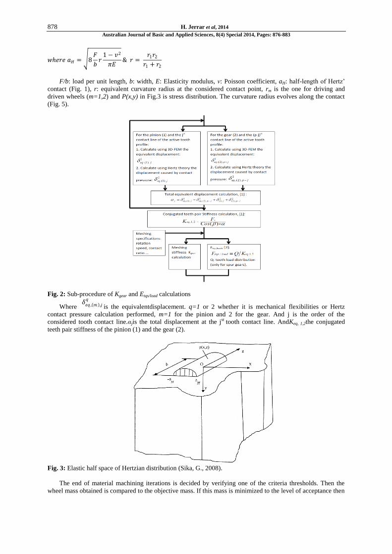
The procedure shown in Fig.1 and 2 consists of the following steps:
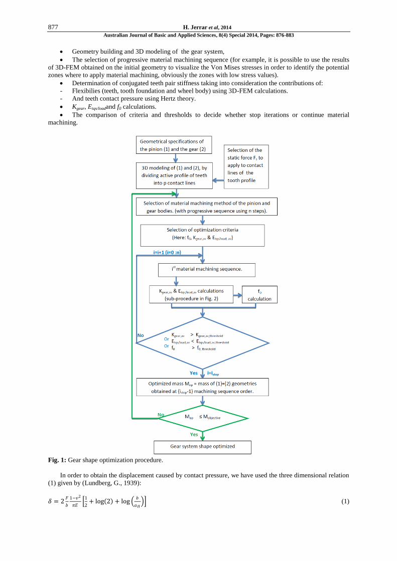
877 H. Jerrar et al, 2014
Australian Journal of Basic and Applied Sciences, 8(4) Special 2014, Pages: 876-883
Geometry building and 3D modeling of the gear system,
The selection of progressive material machining sequence (for example, it is possible to use the results
of 3D-FEM obtained on the initial geometry to visualize the Von Mises stresses in order to identify the potential
zones where to apply material machining, obviously the zones with low stress values).
Determination of conjugated teeth pair stiffness taking into consideration the contributions of:
- Flexibilies (teeth, tooth foundation and wheel body) using 3D-FEM calculations.
- And teeth contact pressure using Hertz theory.
Kgear, Etqs/loadand f0 calculations.
The comparison of criteria and thresholds to decide whether stop iterations or continue material
machining.
Fig. 1: Gear shape optimization procedure.
In order to obtain the displacement caused by contact pressure, we have used the three dimensional relation
(1) given by (Lundberg, G., 1939):
𝛿 = 2𝐹
𝑏
1−𝑣2
𝜋𝐸
1
2+ log 2 + log
𝑏
𝑎𝐻 (1)
878 H. Jerrar et al, 2014
Australian Journal of Basic and Applied Sciences, 8(4) Special 2014, Pages: 876-883
𝑤𝑒𝑟𝑒 𝑎𝐻 = 8𝐹
𝑏𝑟
1 − 𝑣2
𝜋𝐸& 𝑟 =
𝑟1𝑟2
𝑟1 + 𝑟2
F/b: load per unit length, b: width, E: Elasticity modulus, ν: Poisson coefficient, aH: half-length of Hertz’
contact (Fig. 1), r: equivalent curvature radius at the considered contact point, rm is the one for driving and
driven wheels (m=1,2) and P(x,y) in Fig.3 is stress distribution. The curvature radius evolves along the contact
(Fig. 5).
Fig. 2: Sub-procedure of Kgear and Etqs/load calculations
Where 𝛿𝑒𝑞 , 𝑚 ,𝑗
𝑞
is the equivalentdisplacement. q=1 or 2 whether it is mechanical flexibilities or Hertz
contact pressure calculation performed, m=1 for the pinion and 2 for the gear. And j is the order of the
considered tooth contact line.αjis the total displacement at the jst tooth contact line. AndKeq, 1,2the conjugated
teeth pair stiffness of the pinion (1) and the gear (2).
Fig. 3: Elastic half space of Hertzian distribution (Sika, G., 2008).
The end of material machining iterations is decided by verifying one of the criteria thresholds. Then the
wheel mass obtained is compared to the objective mass. If this mass is minimized to the level of acceptance then
879 H. Jerrar et al, 2014
Australian Journal of Basic and Applied Sciences, 8(4) Special 2014, Pages: 876-883
the wheel is optimized, if not: the material removal method need to be changed or combined to others (for
example use the drilling in addition to thickness reduction).
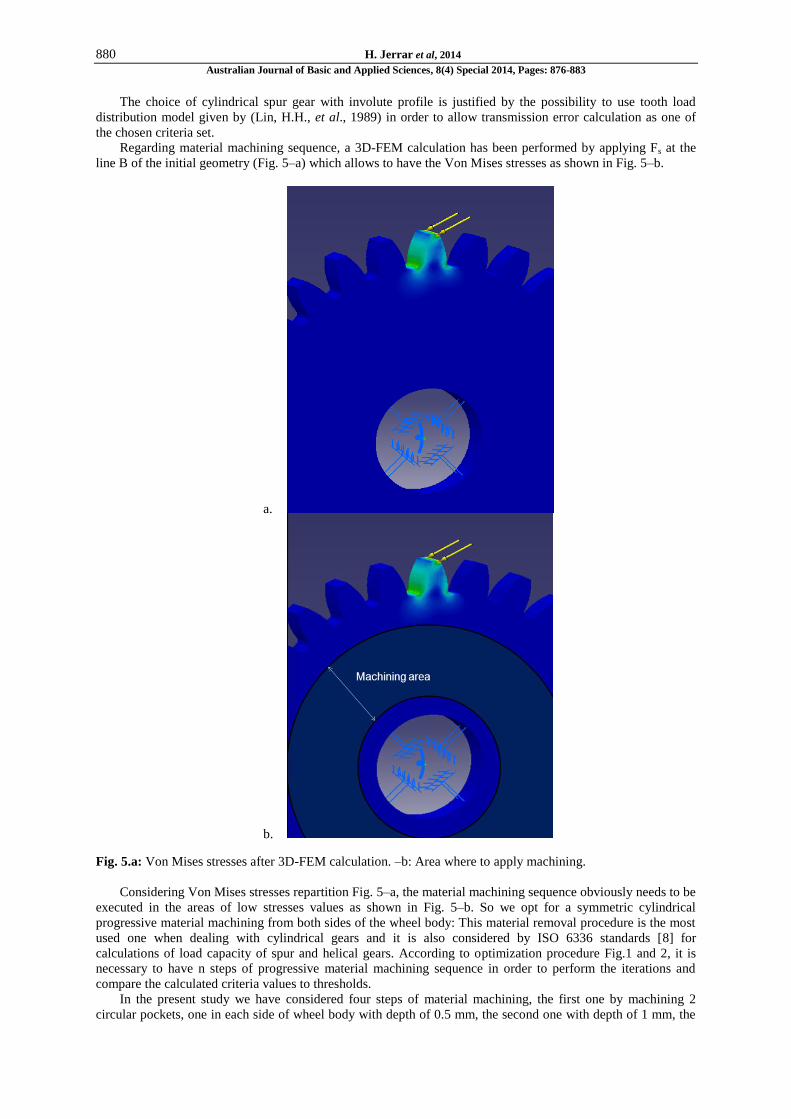
Application:
The present procedure has been applied to the example presented in (Karra, C., et al., 2009) which
corresponds to a bi-dimensional FEM model used to determine the parameter Kgear. This example corresponds to
a spur gear system in which both gears are identical: Fig. 4–a and 4–b. Its geometrical characteristics are
indicated in table 1.
Table 1: Characteristics of the spur gear.
Gear characteristics Gear characteristics
Teeth number 28 Helix angle (β) 0 °
Face width (W) 6.250 mm Dedendum factor 1.4 Tooth root radius 0.635 mm Lug factor 1
Modulus 3.175 mm Contact ratio 1.5674
Pressure angle (ψ) 20° Tooth profile type Involute Pressure angle (β) 0°
Geometry building of the tooth and preparation of the points belonging to spur tooth profile are depicted in
Fig. 4–c.
The wheel is embedded at its inner diameter and a static force Fs=1.615 N is applied vertically to the tooth
profile at each contact line progressively to simulate the contact evolution between the pair of conjugated teeth
in meshing (Fig. 4–e and 4–f).
Fig. 4-a: geometrical specifications (mm) of the gear. –b: 3D snapshot of the reversible gear system –c : 2D
gear geometrical building and preparation of points dividing the active involute profile. –d: Curvature
radius to be used in Lundberg formula. –e & f: Contact lines and Fs application.
880 H. Jerrar et al, 2014
Australian Journal of Basic and Applied Sciences, 8(4) Special 2014, Pages: 876-883
The choice of cylindrical spur gear with involute profile is justified by the possibility to use tooth load
distribution model given by (Lin, H.H., et al., 1989) in order to allow transmission error calculation as one of
the chosen criteria set.
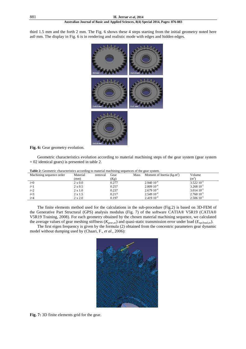
Regarding material machining sequence, a 3D-FEM calculation has been performed by applying Fs at the
line B of the initial geometry (Fig. 5–a) which allows to have the Von Mises stresses as shown in Fig. 5–b.
a.
b.
Fig. 5.a: Von Mises stresses after 3D-FEM calculation. –b: Area where to apply machining.
Considering Von Mises stresses repartition Fig. 5–a, the material machining sequence obviously needs to be
executed in the areas of low stresses values as shown in Fig. 5–b. So we opt for a symmetric cylindrical
progressive material machining from both sides of the wheel body: This material removal procedure is the most
used one when dealing with cylindrical gears and it is also considered by ISO 6336 standards [8] for
calculations of load capacity of spur and helical gears. According to optimization procedure Fig.1 and 2, it is
necessary to have n steps of progressive material machining sequence in order to perform the iterations and
compare the calculated criteria values to thresholds.
In the present study we have considered four steps of material machining, the first one by machining 2
circular pockets, one in each side of wheel body with depth of 0.5 mm, the second one with depth of 1 mm, the
881 H. Jerrar et al, 2014
Australian Journal of Basic and Applied Sciences, 8(4) Special 2014, Pages: 876-883
third 1.5 mm and the forth 2 mm. The Fig. 6 shows these 4 steps starting from the initial geometry noted here
as0 mm. The display in Fig. 6 is in rendering and realistic mode with edges and hidden edges.
Fig. 6: Gear geometry evolution.
Geometric characteristics evolution according to material machining steps of the gear system (gear system
= 02 identical gears) is presented in table 2.
Table 2: Geometric characteristics according to material machining sequences of the gear system.
Machining sequence order Material removal
(mm)
Gear Mass
(Kg)
Moment of Inertia (kg.m2) Volume
(m3)
i=0 2 x 0.0 0.277 2.940 10-4 3.522 10-5 i=1 2 x 0.5 0.257 2.809 10-4 3.268 10-5
i=2 2 x 1.0 0.237 2.679 10-4 3.014 10-5
i=3 2 x 1.5 0.217 2.549 10-4 2.760 10-5 i=4 2 x 2.0 0.197 2.419 10-4 2.506 10-5
The finite elements method used for the calculations in the sub-procedure (Fig.2) is based on 3D-FEM of
the Generative Part Structural (GPS) analysis modulus (Fig. 7) of the software CATIA® V5R19 (CATIA®
V5R19 Training, 2008). For each geometry obtained by the chosen material machining sequence, we calculated
the average values of gear meshing stiffness (Kgear,av) and quasi-static transmission error under load (Etqs/load,av).
The first eigen frequency is given by the formula (2) obtained from the concentric parameters gear dynamic
model without dumping used by (Chaari, F., et al., 2006):
Fig. 7: 3D finite elements grid for the gear.
882 H. Jerrar et al, 2014
Australian Journal of Basic and Applied Sciences, 8(4) Special 2014, Pages: 876-883
𝑓0= 𝜔 02𝜋
𝑤𝑒𝑟𝑒 𝜔0 = 𝐾𝑔𝑒𝑎𝑟 ,𝑎𝑣(𝐽1 𝑟2
2+𝐽2 𝑟12)
𝐽1 𝐽2 (2)
Where Jm and rm are respectively the moment of inertia and pitch radius of the wheel m, m=1 (pinion) and
m=2 (gear). The results are depicted in table 3:
Table 3: Results of optimization procedure application
Machining sequence order (Pinion + Gear) Mass (Kg)
f0
(kHz) Kgear, av (N/m)
Etqs/load, av
(µm)
i=0 0.554 5.348 84.012 106 22.62
i=1 0.514 5.395 81.675 106 23.31 i=2 0.474 5.396 77.925 106 24.48
i=3 0.434 5.377 73.050 106 26.16
i=4 0.394 5.208 65.550 106 29.24
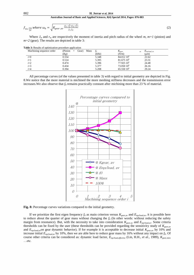
All percentage curves (of the values presented in table 3) with regard to initial geometry are depicted in Fig.
8.We notice that the more material is michined the more meshing stiffness decreases and the transmission error
increases.We also observe that f0 remains practically constant after michining more than 23 % of material.
Fig. 8: Percentage curves variations compared to the initial geometry.
If we prioritize the first eigen frequency f0 as main criterion versus Kgear,av and Etqs/load,av, it is possible here
to reduce about the quarter of gear mass without changing the f0 (In other words: without reducing the safety
margin from resonance). But, with the necessity to take into consideration Kgear,av and Etqs/load,av. Some criteria
thresholds can be fixed by the user (these thresholds can be provided regarding the sensitivity study of Kgear,av
and Etqs/load,avon gear dynamic behavior). If for example it is acceptable to decrease initial Kgear,av by 10% and
increase initial Etqs/load,av by 10%, then we are able here to reduce gear mass by 16% without any impact on f0. Of
course other criteria can be considered as: dynamic load factor, Etqs/load,effective (Lin, H.H., et al., 1989), Kgear,min,
…etc.
0
10
20
30
40
50
60
70
80
90
100
110
120
130
140
0 1 2 3 4 5
%
Machining sequence order i
Percentage curves compared to initial geometry
% Kgear, av
% Etqs/load, av
% f0
% Mass
100%
883 H. Jerrar et al, 2014
Australian Journal of Basic and Applied Sciences, 8(4) Special 2014, Pages: 876-883
Conclusion:
Nowadays, manufacturing light mechanical parts particularly for the industries such as automotive,
aeronautics and navy is becoming more and more demanded in the objective of energy saving, increasing
mechanical structure stiffness and saving expensive special material…etc. To achieve this goal, we have
elaborated and implemented in this paper a shape parametric optimization procedure with criteria related to gear
dynamic behavior. Its application to a spur gear shows the following results:
Using only the f0as main criteria, we are able to reduce considerably (up to a quarter) the gear mass without
any impact on f0.
Taking into consideration other criteria related to gear dynamic behavior (as Kgear,av and Etqs/load,av…etc.)
needs to make compromise between gear mass and dynamic behavior chosen criteria thresholds regarding
sensitivity variations.
Finally, the curves depicted in Fig. 8 provide a decision tool for selecting graphically the optimal shape (for
the studied gear system) by making a compromise between gear mass and chosen dynamic behavior criteria. In
other words, for a gear system and after selecting the appropriate material machining method, the procedure of
Fig.1 and 2 provides by using the maximum of relevant criteria related to dynamic behavior a practical chart (as
in Fig. 8) that helps selecting the optimal shape of this gear system able to operate in certain dynamic
conditions.
As perspectives, the procedure elaborated in Fig.1 and 2 will be fully automated by developing in
Turbomach team a software based on 3D-FEM coupled to meshing stiffness calculation procedure to allow
converging to the optimal shape using appropriate optimization algorithms.
REFERENCES
Allaire, G., 2007. Conception optimale de structures, Editions Springer.
Bard, C., 1995. Modélisation du comportement dynamique des transmissions par engrenages, Thèse de
doctorat, INSA de Lyon France.
CATIA® V5R19 Training, 2008. Generative Part Structural analysis fandamentals,© Dassault Systèmes.
Chaari, F., T. Fakhfakh, M. Haddar, 2006. "Simulation numérique du comportement dynamique d’une
transmission par engrenages en présence de défauts de dentures," Mécanique & Industries, n° 6: 625-633.
ISO 6336, 2008. "Calculation of load capacity of spur and helical gears,"International Organization for
Standardization www.iso.org, Geneva Switzerland, publication date.
Karra, C., M. Maatar, M.N. Bettaieb, 2009. "Modélisation bidimensionnelle par éléments finis d’un
engrenage droit: étude de la raideur d’engrènement et des contraintes au pied de la dent ," TCSME Transactions
of the Canadian Society for Mechanical Engineering, 3(N° 2).
Lin, H.H., D.P. Townsend, F.B. Oswald, 1989. "Profile modification to minimize spur gear dynamic
loading,"in Proceedings of the 5th
ASME International Power Transmission and Gearing Conference, Chicago,
1: 455-465.
Lundberg, G., 1939. "Elastiche berührung zweier halbraüne (Elastic contact of two half spaces),"Forschung
auf dem Gebiete des Ingenieurwesens, 10(n° 5): 201-211.
Sika, G., 2008. "Dynamique des transmissions en régime transitoire," Thèse de doctorat, INSA de Lyon
France.


![Research Article Australian Pregnant Women s Awareness of …downloads.hindawi.com/journals/jp/2016/8162645.pdf · 2019-07-30 · food choices) [ , ] . us research is required that](https://img.pdfslide.us/doc/110x75/5f0cd1887e708231d43748b4/research-article-australian-pregnant-women-s-awareness-of-2019-07-30-food-choices.jpg)