Embed Size (px)
Citation preview
Australian Journal of Basic and Applied Sciences, 5(11): 589-601, 2011 ISSN 1991-8178
Corresponding Author: Javad Mohammadi, Department of Mining Engineering, Islamic Azad University Tehran South Branch, Iran. E-mail: [email protected] Tel: +988612229073
589
Tunnel Face Stability Analysis in Soft Ground in Urban Tunneling by EPB Shield. (Case Study: 7th Line in Tehran Metro)
1Javad Mohammadi, 2Kourosh Shahriar, 2Parviz Moarefvand
1Department of Mining Engineering, Islamic Azad University Tehran South Branch, Iran.
2Department of Mining, Metallurgy and Petroleum Engineering, Amirkabir University of Technology, Hafez 424, Tehran 15875-4413, Iran.
Abstract: Traffic congestion and environmental factors are creating a demand for greater utilization of underground spaces in urban areas. In mechanized excavation of subway tunnels, the Earth Pressure Balanced Shield(EPBS) has been developed in the recent decades for managing the instability of the excavation profile in complicated geotechnical conditions in urban areas. During the advancement of an EPBS, the face-stabilizing pressure is one of the most important factors of critical and principle to be evaluated correctly. In tunneling by EPBS, high face pressure often leads to surface upheaval whereas low face pressure leads to sudden collapse of the face and ultimately settlement of the surface. Both of these misevaluated pressures may cause the damages which followed by pert of time and finance. This paper is discussed about urban tunneling by EPBS in soft ground conditions and focused on calculation of face-stabilizing pressure applying to the case of 7th line in Tehran metro project. Face-support pressure is estimated by most current methods of limiting equilibrium analysis and limiting analysis in excavated parts (two stations) of direction with different and difficult geotechnical conditions. Obtained results compared to EPBS operational results which showed the results of Broere analytical method is most attractive and realistic among others. For one of the excavated stations calculated value of the Broere analytical method obtained 78.406 Kpa and EPBS actual value was equal to 81.01 Kpa. Due to results verification that illustrate a good adjustment with the actual values, quantity face-stabilizing pressure is predicted for some of the alignment unexcavated stations (S7, V7, W7 and X7) which can be used in built procedure. Maximum value was quantity 246.351 Kpa for station V7 and minimum value obtained quantity 25.866 Kpa for station W7.
Key words: Tunneling, face-stabilizing pressure, EPBS, analytical method,7th line of Tehran metro.
INTRODUCTION
As excavation of tunnels in unfavorable geotechnical conditions and in heavily populated urban environments is becoming prevalent, the importance of maintaining tunnel face stability is reaching more importance. Ensuring tunnel face stability is directly related to the safe and successful construction of a tunnel. In this context, tunnel face stability analysis directly relates to face-support pressure. The correct evaluating of face pressure to avoid face instability depends on various factors, such as cohesion, friction angle and permeability of the ground, type of the machine, advance rate, unit weight of slurry or conditioned soil, tunnel diameter, overburden, and location of the ground water table. Many researchers have proposed analytical approaches to determine the required pressure to stabilize the tunnel face. Most of them are based either on limiting equilibrium analysis (Broms and Bennmark, 1967; Krause, 1987; Jancsecz and Steiner, 1994; Anagnostou and Kovári, 1996; Broere, 2001; Carranza-Torres, 2004), or limiting analysis (Atkinson and Potts, 1977; Davis, et al., 1980; Leca and Dormieux, 1990). In the first part of the paper, some referenced methods for evaluating the stability of face are presented then project characteristics are described. In the next part face-stabilizing pressure is calculated in two excavated stations of 7th line of Tehran subway (stations N7 and O7) by limiting equilibrium analysis and limiting analysis methods. Then obtained results are compared to face-stabilizing pressures of EPBS operational. In fact, purpose of this comparsion is the selection of the best analytical method for the project. Finally as logical consequence, suitable method is selected among others, and is predicted face-support pressure in unexcavated various parts (stations S7, V7, W7 and X7). Limiting Equilibrium and Limiting Analysis Methods(LEM and LAM): Method of Broms and Bennemark (1967): A well solution based on Tresca material is Broms and Bennemark’s solution. They suggested the stability ratio N (Eq. (1)) for a vertical opening. This solution is independent of the overburden-to-diameter ratio. N=(qs- σT)/cu+(C+R).Y/cu (1)
Aust. J. Basic & Appl. Sci., 5(11): 589-601, 2011
590
Where Y=the total unit weight of the ground, cu=undrained shear strength of the ground, qs=surcharge, R=radius, σT =the minimum face support pressure and C=overburden (cover depth).
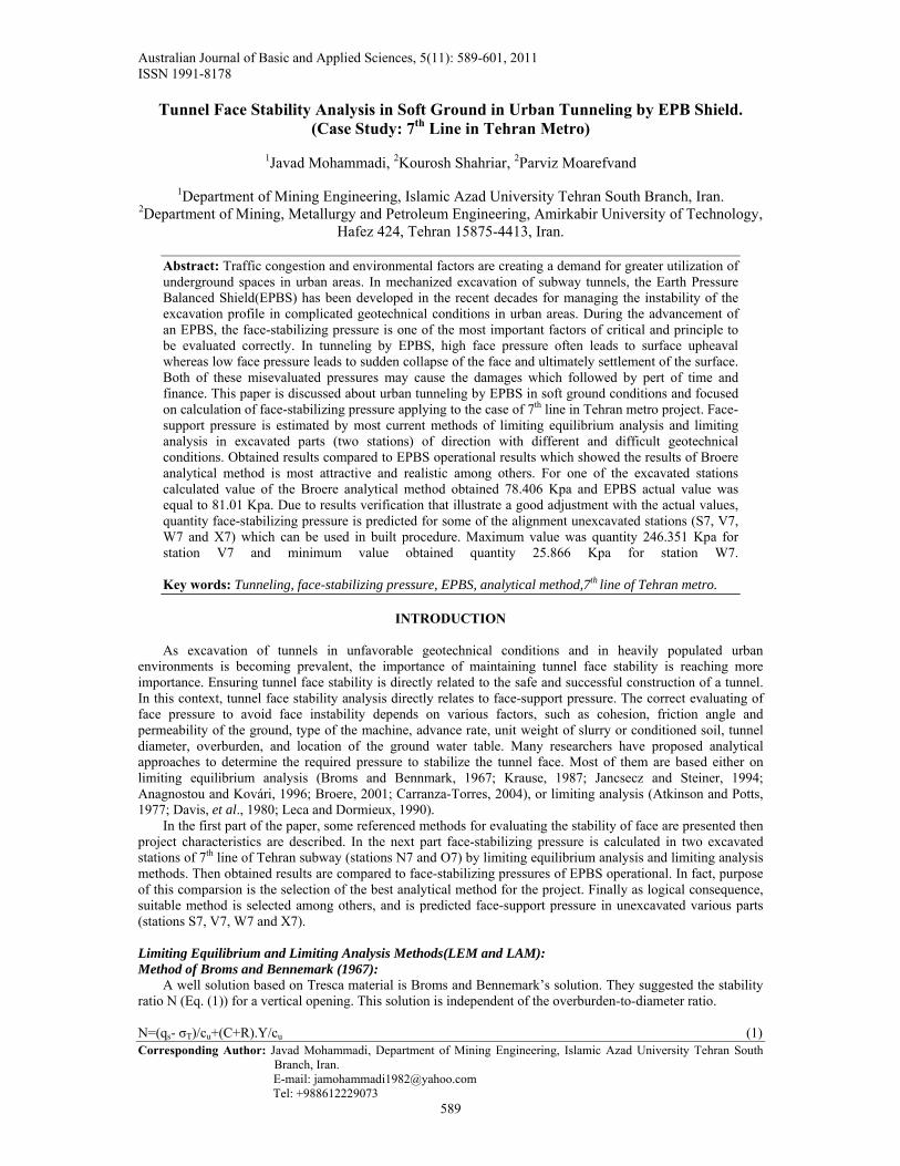
Fig. 1: The tunnel-face stability model of the method of Broms and Bennemark. Empirically, the instability conditions are associated with a value of N ≥ 6. Therefore, the face-stabilizing pressure σT is: σT=Y.(C+R)+qs-N.cu (2) where N=6. Method of (Atkinson and Patts, 1977): Plastic limit analysis approaches employ a plane strain condition. Atkinson and Potts investigated the required support pressure for an unlined tunnel cross section away from tunnel heading in a cohesionless soil. The minimum support pressure(σT) is : σT = 2kpYR/(kp
2-1) (3) where kp=(1+sinø)/(1-sinø) and ø=the soil friction angle.
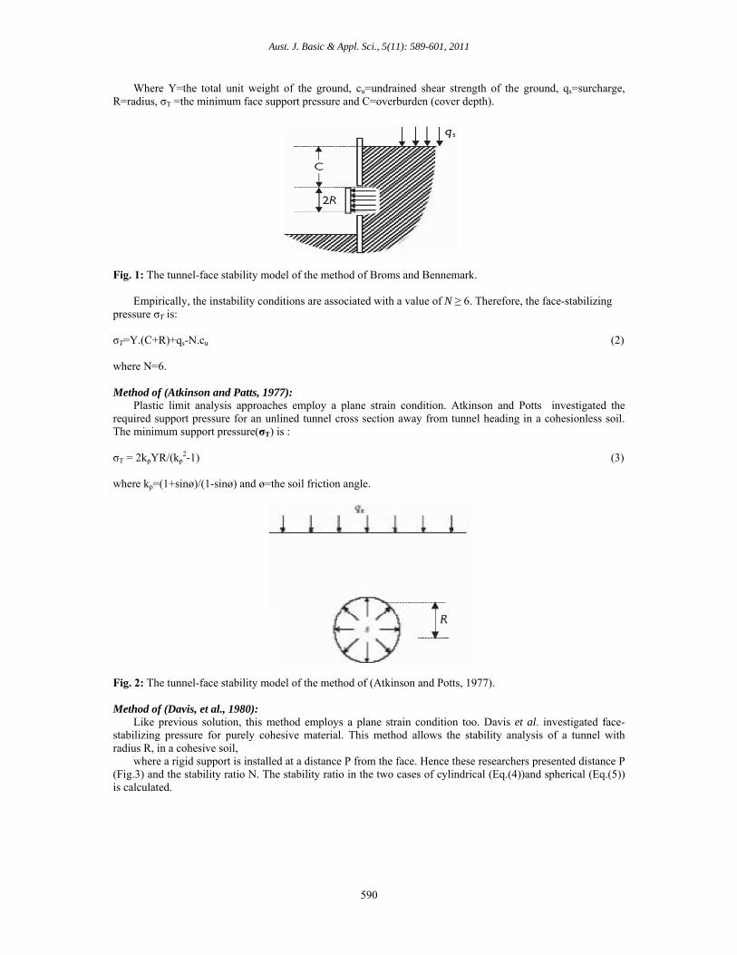
Fig. 2: The tunnel-face stability model of the method of (Atkinson and Potts, 1977). Method of (Davis, et al., 1980): Like previous solution, this method employs a plane strain condition too. Davis et al. investigated face-stabilizing pressure for purely cohesive material. This method allows the stability analysis of a tunnel with radius R, in a cohesive soil, where a rigid support is installed at a distance P from the face. Hence these researchers presented distance P (Fig.3) and the stability ratio N. The stability ratio in the two cases of cylindrical (Eq.(4))and spherical (Eq.(5)) is calculated.
Aust. J. Basic & Appl. Sci., 5(11): 589-601, 2011
591
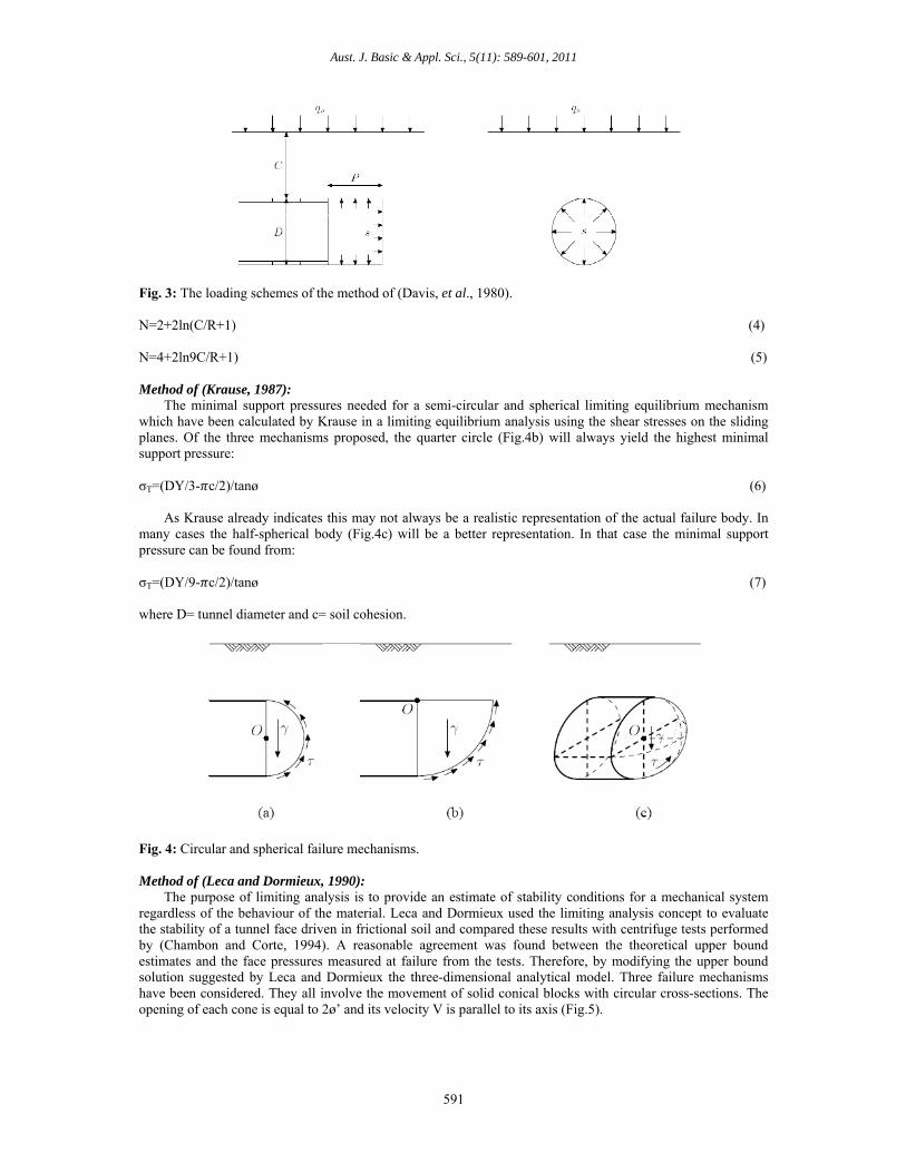
Fig. 3: The loading schemes of the method of (Davis, et al., 1980). N=2+2ln(C/R+1) (4) N=4+2ln9C/R+1) (5) Method of (Krause, 1987): The minimal support pressures needed for a semi-circular and spherical limiting equilibrium mechanism which have been calculated by Krause in a limiting equilibrium analysis using the shear stresses on the sliding planes. Of the three mechanisms proposed, the quarter circle (Fig.4b) will always yield the highest minimal support pressure: σT=(DY/3- c/2)/tanø (6) As Krause already indicates this may not always be a realistic representation of the actual failure body. In many cases the half-spherical body (Fig.4c) will be a better representation. In that case the minimal support pressure can be found from: σT=(DY/9- c/2)/tanø (7) where D= tunnel diameter and c= soil cohesion.
Fig. 4: Circular and spherical failure mechanisms.
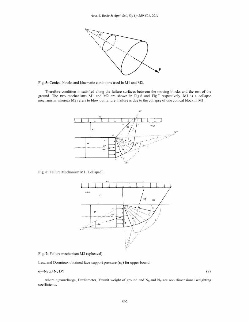
Method of (Leca and Dormieux, 1990): The purpose of limiting analysis is to provide an estimate of stability conditions for a mechanical system regardless of the behaviour of the material. Leca and Dormieux used the limiting analysis concept to evaluate the stability of a tunnel face driven in frictional soil and compared these results with centrifuge tests performed by (Chambon and Corte, 1994). A reasonable agreement was found between the theoretical upper bound estimates and the face pressures measured at failure from the tests. Therefore, by modifying the upper bound solution suggested by Leca and Dormieux the three-dimensional analytical model. Three failure mechanisms have been considered. They all involve the movement of solid conical blocks with circular cross-sections. The opening of each cone is equal to 2ø’ and its velocity V is parallel to its axis (Fig.5).
Aust. J. Basic & Appl. Sci., 5(11): 589-601, 2011
592
Fig. 5: Conical blocks and kinematic conditions used in M1 and M2.
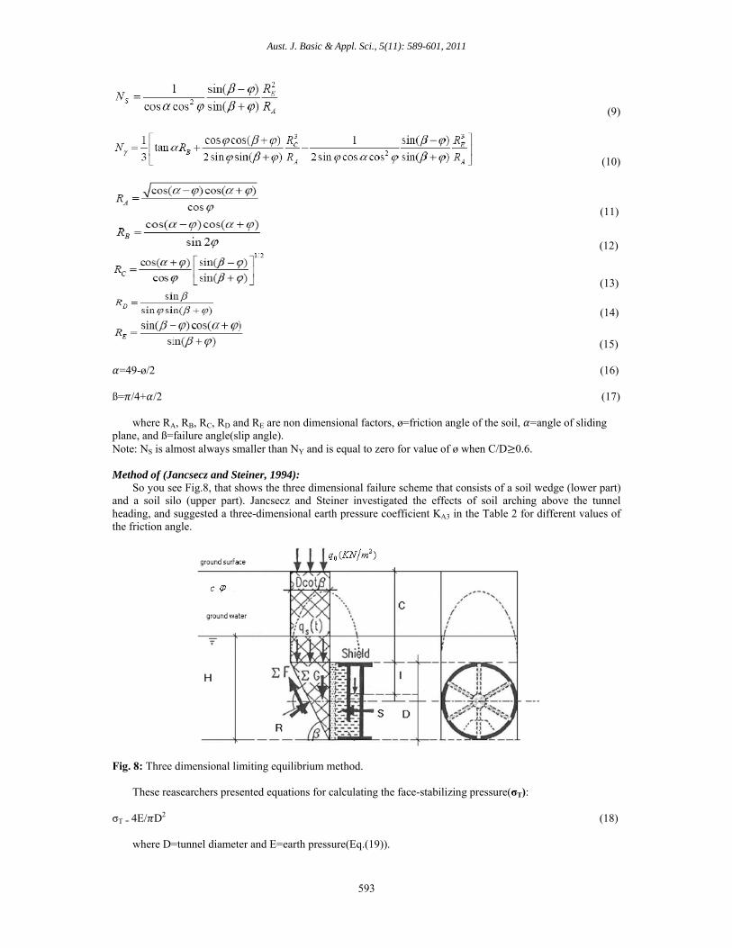
Therefore condition is satisfied along the failure surfaces between the moving blocks and the rest of the ground. The two mechanisms M1 and M2 are shown in Fig.6 and Fig.7 respectively. M1 is a collapse mechanism, whereas M2 refers to blow out failure. Failure is due to the collapse of one conical block in M1.
Fig. 6: Failure Mechanism M1 (Collapse).
Fig. 7: Failure mechanism M2 (upheaval). Leca and Dormieux obtained face-support pressure (σT) for upper bound : σT=NS qs+NY DY (8) where qs=surcharge, D=diameter, Y=unit weight of ground and NS and NY are non dimensional weighting coefficients.
Aust. J. Basic & Appl. Sci., 5(11): 589-601, 2011
593
(9)
(10)
(11)
(12)
(13)
(14)
(15)
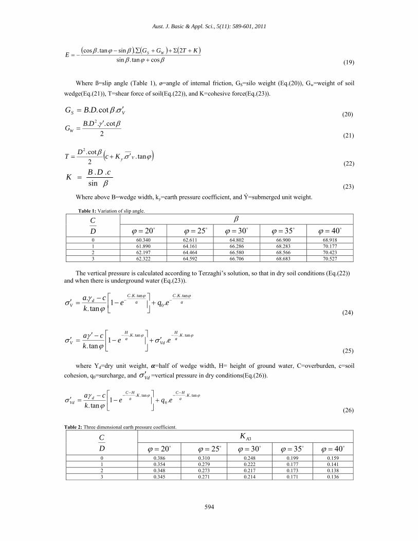
=49-ø/2 (16) ß= /4+ /2 (17) where RA, RB, RC, RD and RE are non dimensional factors, ø=friction angle of the soil, =angle of sliding plane, and ß=failure angle(slip angle). Note: NS is almost always smaller than NY and is equal to zero for value of ø when C/D 0.6. Method of (Jancsecz and Steiner, 1994): So you see Fig.8, that shows the three dimensional failure scheme that consists of a soil wedge (lower part) and a soil silo (upper part). Jancsecz and Steiner investigated the effects of soil arching above the tunnel heading, and suggested a three-dimensional earth pressure coefficient KA3 in the Table 2 for different values of the friction angle.
Fig. 8: Three dimensional limiting equilibrium method. These reasearchers presented equations for calculating the face-stabilizing pressure(σT): σT = 4E/ D2 (18) where D=tunnel diameter and E=earth pressure(Eq.(19)).
Aust. J. Basic & Appl. Sci., 5(11): 589-601, 2011
594
costan.sin
2.sintan.cos
KTGG
E WS
(19)
Where ß=slip angle (Table 1), ø=angle of internal friction, GS=silo weight (Eq.(20)), Gw=weight of soil
wedge(Eq.(21)), T=shear force of soil(Eq.(22)), and K=cohesive force(Eq.(23)).
VS DBG .cot.. (20)
2
cot... 2
DBGW
(21)
tan..
2
cot.2
VyKcD
T (22)
sin
.. cDBK
(23)
Where above B=wedge width, ky=earth pressure coefficient, and Ý=submerged unit weight.
Table 1: Variation of slip angle.
D
C 40
35 30
25 20
68.918 66.900 64.802 62.611 60.340 0 70.177 68.283 66.286 64.161 61.890 1 70.423 68.566 66.580 64.464 62.197 2 70.527 68.683 66.706 64.592 62.322 3
The vertical pressure is calculated according to Terzaghi’s solution, so that in dry soil conditions (Eq.(22)) and when there is underground water (Eq.(23)).
a
KC
a
KCd
V eqek
ca
tan..
0
tan..
.1tan.
.
(24)
tan..tan...1
tan.
Ka
H
Vd
Ka
H
V eek
ca
(25) where Yd=dry unit weight, =half of wedge width, H= height of ground water, C=overburden, c=soil
cohesion, q0=surcharge, and Vd =vertical pressure in dry conditions(Eq.(26)).
tan..
0
tan...1
tan.
Ka
HCK
a
HCd
Vd eqek
ca
(26)
Table 2: Three dimensional earth pressure coefficient.
3AK
D
C
40 35
30 25
20
0.159 0.199 0.248 0.310 0.386 0 0.141 0.177 0.222 0.279 0.354 1 0.138 0.173 0.217 0.273 0.348 2 0.136 0.171 0.214 0.271 0.345 3
Aust. J. Basic & Appl. Sci., 5(11): 589-601, 2011
595
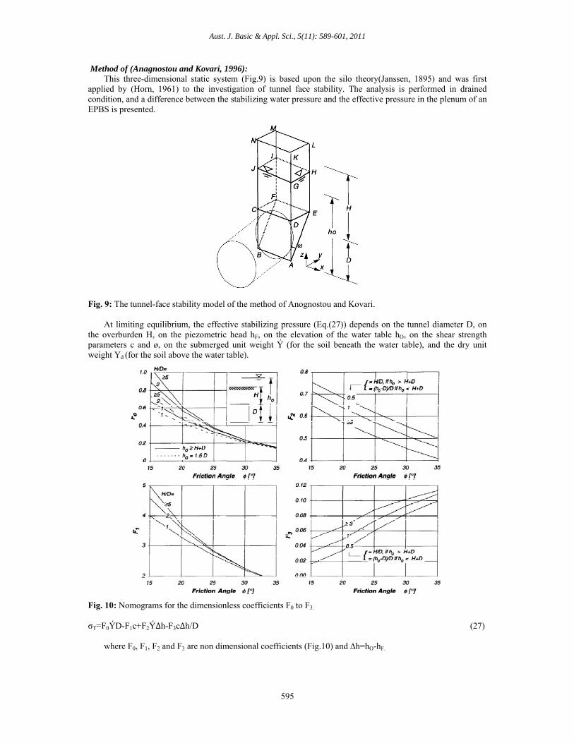
Method of (Anagnostou and Kovari, 1996): This three-dimensional static system (Fig.9) is based upon the silo theory(Janssen, 1895) and was first applied by (Horn, 1961) to the investigation of tunnel face stability. The analysis is performed in drained condition, and a difference between the stabilizing water pressure and the effective pressure in the plenum of an EPBS is presented.
Fig. 9: The tunnel-face stability model of the method of Anognostou and Kovari.
At limiting equilibrium, the effective stabilizing pressure (Eq.(27)) depends on the tunnel diameter D, on the overburden H, on the piezometric head hF, on the elevation of the water table hO, on the shear strength parameters c and ø, on the submerged unit weight Ý (for the soil beneath the water table), and the dry unit weight Yd (for the soil above the water table).
Fig. 10: Nomograms for the dimensionless coefficients F0 to F3.
σT=F0ÝD-F1c+F2Ý∆h-F3c∆h/D (27) where F0, F1, F2 and F3 are non dimensional coefficients (Fig.10) and ∆h=hO-hF.
Aust. J. Basic & Appl. Sci., 5(11): 589-601, 2011
596
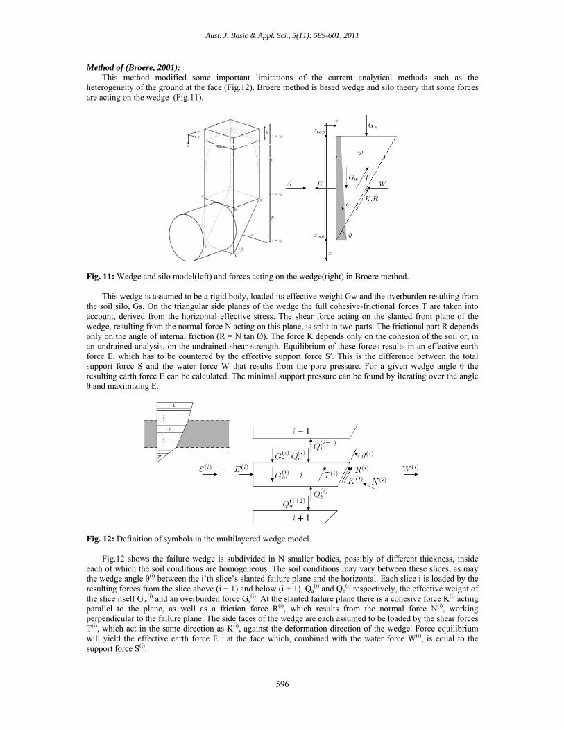
Method of (Broere, 2001): This method modified some important limitations of the current analytical methods such as the heterogeneity of the ground at the face (Fig.12). Broere method is based wedge and silo theory that some forces are acting on the wedge (Fig.11).
Fig. 11: Wedge and silo model(left) and forces acting on the wedge(right) in Broere method. This wedge is assumed to be a rigid body, loaded its effective weight Gw and the overburden resulting from the soil silo, Gs. On the triangular side planes of the wedge the full cohesive-frictional forces T are taken into account, derived from the horizontal effective stress. The shear force acting on the slanted front plane of the wedge, resulting from the normal force N acting on this plane, is split in two parts. The frictional part R depends only on the angle of internal friction (R = N tan Ø). The force K depends only on the cohesion of the soil or, in an undrained analysis, on the undrained shear strength. Equilibrium of these forces results in an effective earth force E, which has to be countered by the effective support force S′. This is the difference between the total support force S and the water force W that results from the pore pressure. For a given wedge angle θ the resulting earth force E can be calculated. The minimal support pressure can be found by iterating over the angle θ and maximizing E.
Fig. 12: Definition of symbols in the multilayered wedge model. Fig.12 shows the failure wedge is subdivided in N smaller bodies, possibly of different thickness, inside each of which the soil conditions are homogeneous. The soil conditions may vary between these slices, as may the wedge angle θ(i) between the i’th slice’s slanted failure plane and the horizontal. Each slice i is loaded by the resulting forces from the slice above (i − 1) and below (i + 1), Qa
(i) and Qb(i) respectively, the effective weight of
the slice itself Gw(i) and an overburden force Gs
(i). At the slanted failure plane there is a cohesive force K(i) acting parallel to the plane, as well as a friction force R(i), which results from the normal force N(i), working perpendicular to the failure plane. The side faces of the wedge are each assumed to be loaded by the shear forces T(i), which act in the same direction as K(i), against the deformation direction of the wedge. Force equilibrium will yield the effective earth force E(i) at the face which, combined with the water force W(i), is equal to the support force S(i).

Aust. J. Basic & Appl. Sci., 5(11): 589-601, 2011
597
There is vertical and horizontal equilibrium in condition of:
0sincoscos2 iiiiiiii NRKTE (28)
0cossinsin2 iiiiiiiib
iw
is
ia NRKTQGGQ
(29) iii NR tan
(30)
Combination of equations (28) and (29) lead to:
011
2
i
ii
ii
iii
bi
ai
wi
s EKTQQGG
(31) Because of shorthand notation:
cossintan (32) sincostan (33)
Each slice has to satisfy the equilibrium as well as the continuity condition:
1 ib
ia QQ
(34)
Boundary conditions: 0NbQ and
01 aQ
For slice N:
1
1111 12
12
NN
NNN
wN
wN
sN
sN
bN
a TTGGGGQQ (35)
This result can be combined with the equilibrium relation for slice N-1:
1
11121 12
12
NN
NNN
WN
WN
SN
SN
bN
a TTGGGGQQ
1
11
11 11
N
NN
N
NN
NN
NN EEKK
(36)
Where
N
i
iiiWS KTGGE
1
21
(37) S=E+W (38) And so on the above equations, finally minimum face-stabilizing pressure( T) is equal to:
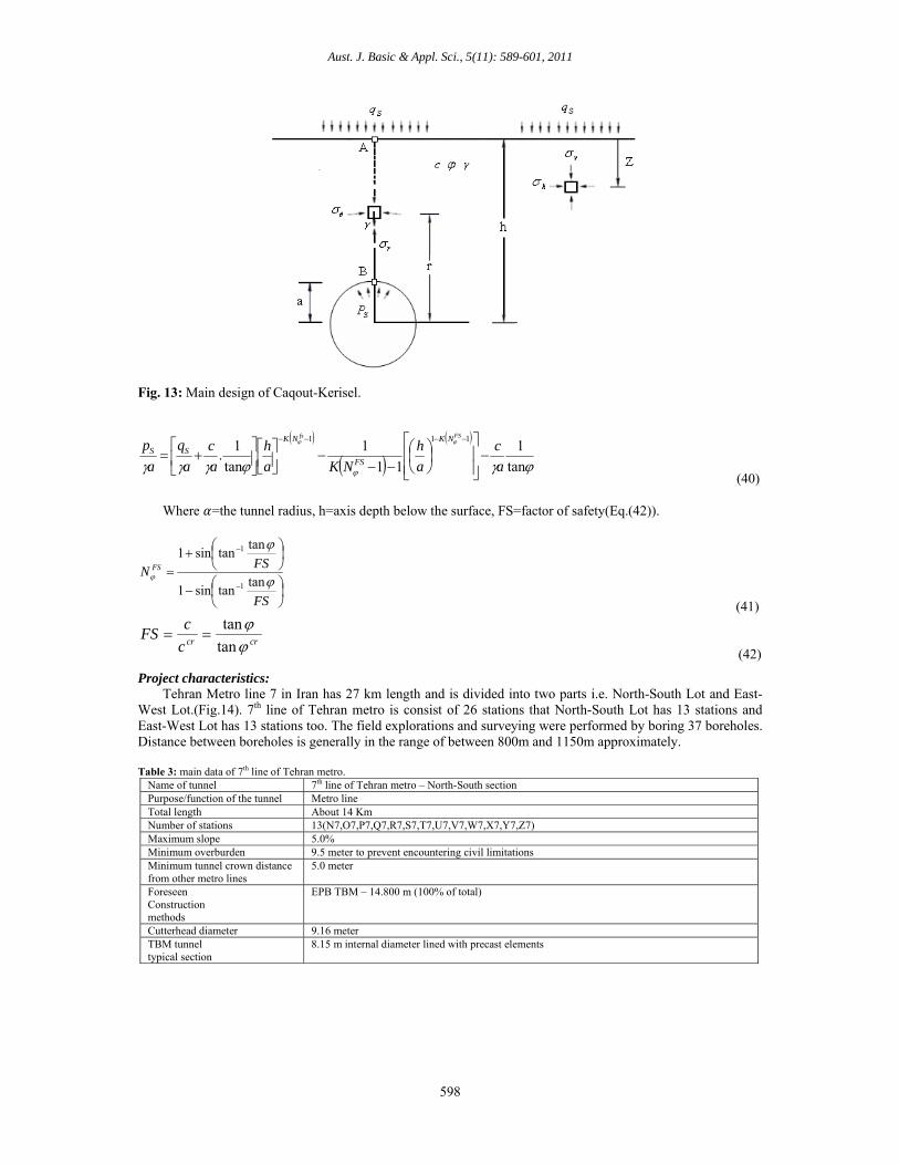
T=4S/ D2 (39) Method of (Carranza-Torres, 2004): Carranza-Torres integrated method of (Caqout-Kerisel, 1956).Carranza’s model considers the equilibrium condition for material undergoing failure above the crown of a shallow circular (cylindrical or spherical) cavity. The material has a unit weight γ and a shear strength defined by Mohr-Coulomb parameters c and φ, the cohesion and the friction angle respectively. A support pressure Ps is applied inside the tunnel, while a surcharge qs acts on the ground surface. For the situation presented in the Fig.13, Carranza’s solution defines the value of face-stabilizing pressure (Ps) as the minimum or critical pressure below which the tunnel will collapse:
Aust. J. Basic & Appl. Sci., 5(11): 589-601, 2011
598
Fig. 13: Main design of Caqout-Kerisel.
tan
1
11
1
tan
1.
111
a
c
a
h
NKa
h
a
c
a
q
a
pFSfs NK
FS
NK
SS
(40)
Where =the tunnel radius, h=axis depth below the surface, FS=factor of safety(Eq.(42)).
FS
FSN FS
tantansin1
tantansin1
1
1
(41)
crcrc
cFS
tan
tan
(42)
Project characteristics:
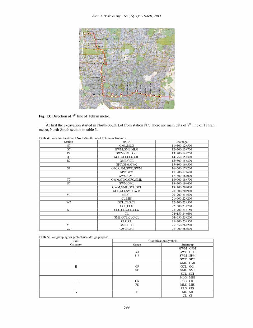
Tehran Metro line 7 in Iran has 27 km length and is divided into two parts i.e. North-South Lot and East-West Lot.(Fig.14). 7th line of Tehran metro is consist of 26 stations that North-South Lot has 13 stations and East-West Lot has 13 stations too. The field explorations and surveying were performed by boring 37 boreholes. Distance between boreholes is generally in the range of between 800m and 1150m approximately. Table 3: main data of 7th line of Tehran metro.
Name of tunnel 7th line of Tehran metro – North-South section Purpose/function of the tunnel Metro line Total length About 14 Km Number of stations 13(N7,O7,P7,Q7,R7,S7,T7,U7,V7,W7,X7,Y7,Z7) Maximum slope 5.0% Minimum overburden 9.5 meter to prevent encountering civil limitations Minimum tunnel crown distance from other metro lines
5.0 meter
Foreseen Construction methods
EPB TBM – 14.800 m (100% of total)
Cutterhead diameter 9.16 meter TBM tunnel typical section
8.15 m internal diameter lined with precast elements
Aust. J. Basic & Appl. Sci., 5(11): 589-601, 2011
599
Fig. 13: Direction of 7th line of Tehran metro. At first the excavation started in North-South Lot from station N7. There are main data of 7th line of Tehran metro, North-South section in table 3. Table 4: Soil classification of North-South Lot of Tehran metro line 7.
ChainageBSCSStation 11+500-12+500 GML,MLG N7 12+500-13+700 GWM,GML,MLG O7 13+700-14+750 GWM,GML,GCI P7 14+750-15+300 GCL,GCI,CLG,CIG Q7 15+300-15+800 GML,GCL R7 15+800-16+500 GPC,GPM,GWC 16+500-17+200 GPC,GPM,GWC,GWM S7 17+200-17+600 GPC,GPM 17+600-18+000 GWM,GML 18+000-18+700 GWM,GWC,GPC,GML T7 18+700-19+400 GWM,GML U7 19+400-20+000 GWM,GML,GCL,GCI 20+000-20+900 GCL,GCI,SMI,GWM 20+900-21+600 ML,CL V7 21+600-22+200 CL,MIS 22+200-22+500 GCL,CLG,CL W7 22+500-23+700 GCL,CLG 23+700-24+150 CLG,CL,GCL,CLG X7 24+150-24+650 CL 24+650-25+200 GML,GCL,CLG,CL 25+200-25+550 CLG,CL 25+550-26+200 GML,CLG Y7 26+200-26+600 GWC,GPC Z7
Table 5: Soil grouping for geotechnical design purpose.
Soil Category
Classification Symbols Group Subgroup
I
G-F S-F
GWM , GPM GWC , GPC SWM , SPM SWC , SPC
II
GF SF
GML , GMI GCL , GCI SML , SMI SCL , SCI
III
FG FS
MLG , MIG CLG , CIG MLS , MIS CLS , CIS
IV F ML , MI CL , CI
Aust. J. Basic & Appl. Sci., 5(11): 589-601, 2011
600
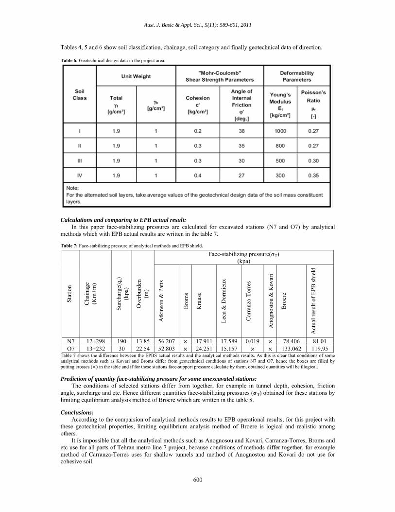
Tables 4, 5 and 6 show soil classification, chainage, soil category and finally geotechnical data of direction. Table 6: Geotechnical design data in the project area.
Calculations and comparing to EPB actual result: In this paper face-stabilizing pressures are calculated for excavated stations (N7 and O7) by analytical methods which with EPB actual results are written in the table 7. Table 7: Face-stabilizing pressure of analytical methods and EPB shield.
Table 7 shows the difference between the EPBS actual results and the analytical methods results. As this is clear that conditions of some analytical methods such as Kovari and Broms differ from geotechnical conditions of stations N7 and O7, hence the boxes are filled by putting crosses ( in the table and if for these stations face-support pressure calculate by them, obtained quantities will be illogical.
Prediction of quantity face-stabilizing pressure for some unexcavated stations: The conditions of selected stations differ from together, for example in tunnel depth, cohesion, friction angle, surcharge and etc. Hence different quantities face-stabilizing pressures ( T) obtained for these stations by limiting equilibrium analysis method of Broere which are written in the table 8.
Conclusions: According to the comparsion of analytical methods results to EPB operational results, for this project with these geotechnical properties, limiting equilibrium analysis method of Broere is logical and realistic among others. It is impossible that all the analytical methods such as Anognosou and Kovari, Carranza-Torres, Broms and etc use for all parts of Tehran metro line 7 project, because conditions of methods differ together, for example method of Carranza-Torres uses for shallow tunnels and method of Anognostou and Kovari do not use for cohesive soil.
Sta
tion
Cha
inag
e (K
m+
m)
Sur
char
ge(q
s)
(kpa
)
Ove
rbur
den
(m)
Face-stabilizing pressure( T) (kpa)
Atk
inso
n &
Pat
ts
Bro
ms
Kra
use
Lec
a &
Dor
mie
ux
Car
ranz
a-T
orre
s
Ano
gnos
tou
& K
ovar
i
Bro
ere
Act
ual r
esul
t of
EP
B s
hiel
d
N7 12+298 190 13.85 56.207 17.911 17.589 0.019 78.406 81.01 O7 13+232 30 22.54 52.803 24.251 15.157 133.062 119.95
Aust. J. Basic & Appl. Sci., 5(11): 589-601, 2011
601
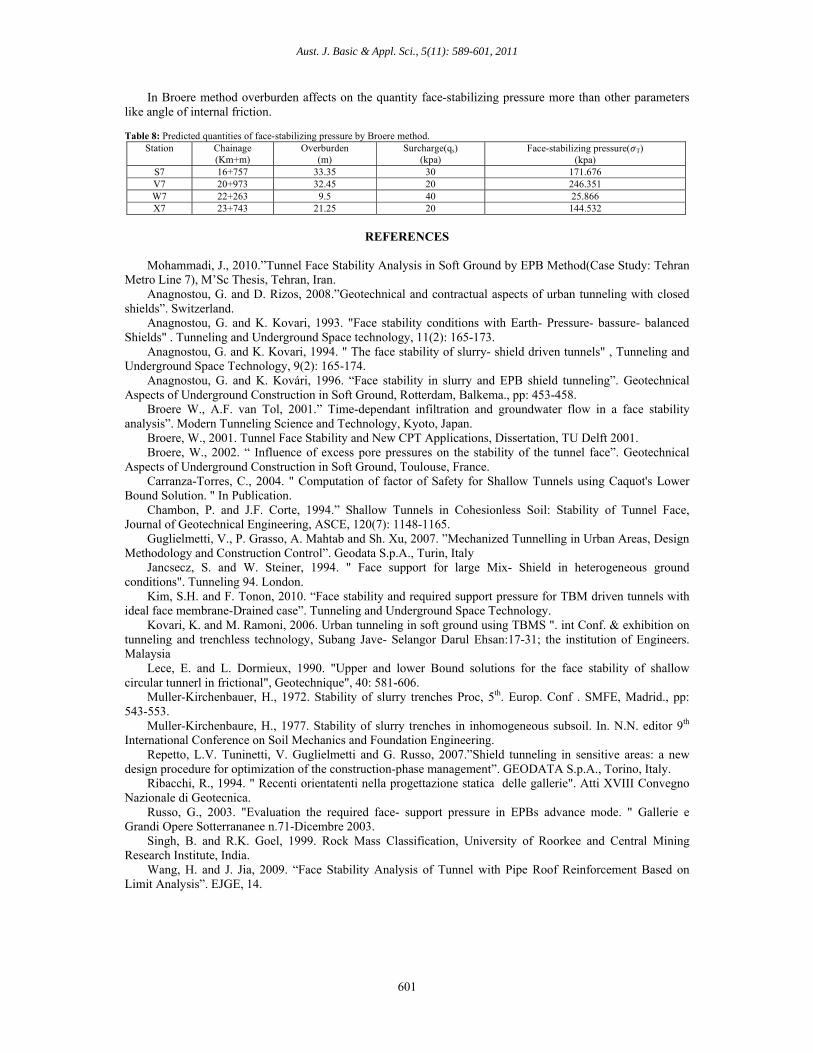
In Broere method overburden affects on the quantity face-stabilizing pressure more than other parameters like angle of internal friction. Table 8: Predicted quantities of face-stabilizing pressure by Broere method.
Station Chainage (Km+m)
Overburden (m)
Surcharge(qs) (kpa)
Face-stabilizing pressure( T) (kpa)
S7 16+757 33.35 30 171.676 V7 20+973 32.45 20 246.351 W7 22+263 9.5 40 25.866 X7 23+743 21.25 20 144.532
REFERENCES
Mohammadi, J., 2010.”Tunnel Face Stability Analysis in Soft Ground by EPB Method(Case Study: Tehran Metro Line 7), M’Sc Thesis, Tehran, Iran. Anagnostou, G. and D. Rizos, 2008.”Geotechnical and contractual aspects of urban tunneling with closed shields”. Switzerland. Anagnostou, G. and K. Kovari, 1993. "Face stability conditions with Earth- Pressure- bassure- balanced Shields" . Tunneling and Underground Space technology, 11(2): 165-173. Anagnostou, G. and K. Kovari, 1994. " The face stability of slurry- shield driven tunnels" , Tunneling and Underground Space Technology, 9(2): 165-174. Anagnostou, G. and K. Kovári, 1996. “Face stability in slurry and EPB shield tunneling”. Geotechnical Aspects of Underground Construction in Soft Ground, Rotterdam, Balkema., pp: 453-458. Broere W., A.F. van Tol, 2001.” Time-dependant infiltration and groundwater flow in a face stability analysis”. Modern Tunneling Science and Technology, Kyoto, Japan. Broere, W., 2001. Tunnel Face Stability and New CPT Applications, Dissertation, TU Delft 2001. Broere, W., 2002. “ Influence of excess pore pressures on the stability of the tunnel face”. Geotechnical Aspects of Underground Construction in Soft Ground, Toulouse, France. Carranza-Torres, C., 2004. " Computation of factor of Safety for Shallow Tunnels using Caquot's Lower Bound Solution. " In Publication. Chambon, P. and J.F. Corte, 1994.” Shallow Tunnels in Cohesionless Soil: Stability of Tunnel Face, Journal of Geotechnical Engineering, ASCE, 120(7): 1148-1165. Guglielmetti, V., P. Grasso, A. Mahtab and Sh. Xu, 2007. ”Mechanized Tunnelling in Urban Areas, Design Methodology and Construction Control”. Geodata S.p.A., Turin, Italy Jancsecz, S. and W. Steiner, 1994. " Face support for large Mix- Shield in heterogeneous ground conditions". Tunneling 94. London. Kim, S.H. and F. Tonon, 2010. “Face stability and required support pressure for TBM driven tunnels with ideal face membrane-Drained case”. Tunneling and Underground Space Technology. Kovari, K. and M. Ramoni, 2006. Urban tunneling in soft ground using TBMS ". int Conf. & exhibition on tunneling and trenchless technology, Subang Jave- Selangor Darul Ehsan:17-31; the institution of Engineers. Malaysia Lece, E. and L. Dormieux, 1990. "Upper and lower Bound solutions for the face stability of shallow circular tunnerl in frictional", Geotechnique", 40: 581-606. Muller-Kirchenbauer, H., 1972. Stability of slurry trenches Proc, 5th. Europ. Conf . SMFE, Madrid., pp: 543-553. Muller-Kirchenbaure, H., 1977. Stability of slurry trenches in inhomogeneous subsoil. In. N.N. editor 9th International Conference on Soil Mechanics and Foundation Engineering. Repetto, L.V. Tuninetti, V. Guglielmetti and G. Russo, 2007.”Shield tunneling in sensitive areas: a new design procedure for optimization of the construction-phase management”. GEODATA S.p.A., Torino, Italy. Ribacchi, R., 1994. " Recenti orientatenti nella progettazione statica delle gallerie". Atti XVIII Convegno Nazionale di Geotecnica. Russo, G., 2003. "Evaluation the required face- support pressure in EPBs advance mode. " Gallerie e Grandi Opere Sotterrananee n.71-Dicembre 2003. Singh, B. and R.K. Goel, 1999. Rock Mass Classification, University of Roorkee and Central Mining Research Institute, India. Wang, H. and J. Jia, 2009. “Face Stability Analysis of Tunnel with Pipe Roof Reinforcement Based on Limit Analysis”. EJGE, 14.