Embed Size (px)
Citation preview

Self-Diffusiophoresis of Janus Catalytic Micromotors in ConfinedGeometriesFengchang Yang,† Shizhi Qian,‡ Yiping Zhao,§ and Rui Qiao*,†
†Department of Mechanical Engineering, Virginia Polytechnic Institute and State University, 460 Old Turner Street, Blacksburg,Virginia 24061, United States‡Department of Mechanical & Aerospace Engineering, Old Dominion University, 5115 Hampton Boulevard, Norfolk, Virginia 23529,United States§Department of Physics and Astronomy, The University of Georgia, Athens, Georgia 30602, United States
*S Supporting Information
ABSTRACT: The self-diffusiophoresis of Janus catalytic micromotors (JCMs) inconfined environment is studied using direct numerical simulations. Thesimulations revealed that, on average, the translocation of a JCM through ashort pore is moderately slowed down by the confinement. This slowdown is farweaker compared to the transport of particles through similar pores driven byforces induced by external means or passive diffusiophoresis. Pairing of two JCMsfacilitates the translocation of the one JCM entering the pore first but slows downthe second JCM. Depending on its initial orientation, a JCM near the entrance ofa pore can exhibit different rotational motion, which determines whether it canenter the pore. Once a JCM enters a narrow pore, it can execute a self-alignmentprocess after which it becomes fully aligned with the pore axis and moves to thecenter line of the pore. Analysis of these results showed that, in addition tohydrodynamic effect, the translation and rotation of JCM is also affected by the “chemical effects”, i.e., the modification of thechemical species concentration around a JCM by confining walls and neighboring JCMs. These chemical effects are unique to theself-diffusiophoresis of JCMs and should be considered in design and operations of JCMs in confined environment.
1. INTRODUCTION
Janus catalytic micromotors (JCMs) are micro/nanoscaleparticles that feature heterogeneous catalytic coating on theirsurfaces. By using the catalytic reactions on their surfaces tobreak down the reactants in surrounding fluids, JCMs can“swim” autonomously via various mechanisms. Since achievingautonomous movement of small particulates has long beensought in diverse fields including biology and medicine, thedemonstration of autonomous JCMs about a decade ago1,2 hastriggered intensive studies of JCMs and their dynamics sincethen.3,4 While the practical application of JCMs remains limitedat present, autonomous JCMs have already been usedsuccessfully to sense, detect, and deliver micro/nanoparticlesof various sizes and shape.5−7 With further development, JCMscan conceivably be used to execute more demanding tasks suchas removing blood clots in capillaries and environmentremediation.8,9
The intensive experimental and theoretical studies on JCMshave tremendously improved the fabrication, operation, andunderstanding of JCMs. Several mechanisms including self-diffusiophoresis,10,11 self-electrophoresis,12 and bubble propul-sion13−15 have been revealed to drive JCMs’ movement. Ofthese mechanisms, self-diffusiophoresis and self-electrophore-sis-driven dynamics of JCMs have received the most attention.The effects of JCM design,16,17 operating conditions such assolution composition,18,19 geometrical confinement,20,21 and
externally imposed shear flows on the dynamics of JCM havebeen explored in great detail.22 For the applications of JCMs indrug delivery and microfluidics, the geometrical confinementusually plays an important role in the JCM dynamics. Becauseof the importance of boundaries, several studies recently havesought to understand the role of solid boundaries indetermining the JCM motion. Specifically, the self-diffusiopho-resis of an active particle in the vicinity of a planar boundary hasbeen explored via either experimental or theoretical meth-ods.23−27 For example, Uspal et al. investigated the self-propulsion of a catalytic active particle near a wall by combininganalytical analysis and numerical simulations.23 It wasdiscovered that, depending on the choice of design parameters(catalytic coverage, surface mobility, etc.), the catalytic activeparticle shows different behaviors near a wall includingreflection, steady sliding, and hovering. They suggested thatthe hydrodynamic effect of the wall is mainly responsible forthe behaviors of catalytic active particles. Ibrahim et al. capturedthe wall-induced distortion of solute concentration gradients,which caused wall-induced-diffusiophoresis of JCMs.24 Suchwall-induced-diffusiophoresis promotes the translation of JCMswithout affecting their rotation. Some of the simulation
Received: March 29, 2016Revised: May 16, 2016Published: May 17, 2016
Article
pubs.acs.org/Langmuir
© 2016 American Chemical Society 5580 DOI: 10.1021/acs.langmuir.6b01214Langmuir 2016, 32, 5580−5592

predictions have been observed experimentally; e.g., Kreuter etal. observed sliding and reflection of JCM near channel walls.25
In one recent experimental study, boundaries are used to steerthe motion of JCMs and eliminate the Brownian rotation ofJCM.27 A key concept emerging from these studies is that, inaddition to the hydrodynamic interactions, “chemical” inter-actions can also greatly affect the dynamics of JCMs under wallconfinements. Specifically, the confining walls affect thetransport of reaction product and cause the productconcentration field near the JCM (and consequently the slipvelocity and the viscous stress on the JCM’s surface) to deviatefrom those in bulk solutions. These “chemical” interactions alsoaffect the dynamics of a cluster of particles when they approacheach other.16,28,29
While previous research on JCMs has greatly improved ourunderstanding of their dynamics in free solutions and nearplanar boundaries,11,23,30,31 the dynamics of JCMs in morecomplex environments remain to be clarified. For drug deliveryand microfluidic applications, JCMs often must operate underconfined conditions; e.g., multiple JCMs may come close toeach other and translate through a short micropore. How thedynamics of JCM is changed by the severe confinement is notwell understood. For example, how do JCMs translate througha micropore? Can a JCM enter a pore if it is not perfectlyaligned with the pore axis? How do JCMs disturbed by externalstimulus or thermal fluctuation behave inside a pore? Thereexist a few studies on these questions and useful insights werereported; e.g., the dynamics of catalytic dimer in a channel hasbeen studied using simulations, and the effect of confinementon the reaction product concentration was shown to affect thedimer transport.21 However, in general, research on thesequestions is rather scarce at present. Furthermore, most existingstudies of JCM dynamics are based on quasi-static models. Inthese models, the reaction product concentration field isassumed to have no memory, which may not hold for highlyconfined JCMs.In this work, we solve the fully coupled fluid−structure
interaction problem of JCM locomotion in confined geometriesusing the arbitrary Lagrangian−Eulerian (ALE) method. Thismethod allows us to remove the restriction of assuming quasi-static reaction product concentration field when solving JCMdynamics. The rest of paper is organized as follows: In section2, we introduce the mathematical model of self-diffusiophoresisof JCM and its numerical implementation. In section 3, wesystematically investigate how confinement affects the trans-lation of JCMs through narrow pores, and how JCMs rotatenear the pore entrance and inside short pores. Finally,conclusions are presented in section 4.
2. MATHEMATICAL MODEL AND NUMERICALIMPLEMENTATION2.1. Model for Self-Diffusiophoresis. To focus on the
dynamics of JCMs driven by self-diffusiophoresis, weconsidered spherical JCMs of radius RJCM submerged in asolution (see Figure 1). The JCMs are half-coated by catalyststhat break down fuels in solution by chemical reaction. Thereaction generates a concentration gradient of the reactionproduct along the JCM’s surface. Such a concentration gradientinduces an imbalance of interfacial forces near the JCM’ssurface, thus driving the self-diffusiophoresis of JCM. Inpractice, platinum is often used as catalytic material. Ifhydrogen peroxide is used as fuel, the product of the catalyticreaction is oxygen. Other fuels,32,33 which lead to different
reaction products, can also be used. Here, to reduce thenumerical difficulty, we neglect the transport of fuel and assumethe concentration of fuels does not deviate from the initialconcentration notably in our simulations. This treatment isvalid when the Damkohler number Da is small. Da is the ratioof the diffusion and reactive time scales, i.e., Da = sL/DfCf,where s is the rate at which fuels are consumed on the catalyticsurface, L is the characteristic length scale involved in thesupply of fuel to the catalytic surface, and Df and Cf are thediffusion coefficient and concentration of fuel molecules,respectively. We focus our study in the regime of Da ≪ 1.Hence, the transport of the fuel does not need to be solved.The effect of fuel transport will be studied in the future.To describe the above self-diffusiophoresis of JCMs, we
adopt the general model established previously.10,30,31,34 Briefly,two sets of equations govern the reaction/transport of thereaction products and the movement of the fluids and the JCM.The concentration field of the reaction product (e.g., oxygen),c, is governed by the convection−diffusion equation
∂∂
+ ·∇ = ∇· ∇uct
c D c( )(1)
where D is the diffusion coefficient of the reaction product andu is the fluid velocity. The neutral (noncatalytic) surface of theJCM (i.e., Γ1 in Figure 1) is an impermeable wall, i.e.
− ∇ · = Γx nD c t( , ) 0 on 1 (2)
where n is the unit normal vector of the surface. The generationof reaction products is taken into account through theboundary condition imposed on the catalytic surface (i.e., Γ2in Figure 1)
α− ∇ · = Γx nD c t( , ) on 2 (3)
where α is the rate at which reaction products are generated onthe catalytic surface.We note that, with a few exceptions,30,35 the transient and
convection terms in eq 1 were neglected in most prior studiesof self-diffusiophoresis. This is justified for self-diffusiophoresisin bulk solution or near semi-infinite walls. However, theseterms cannot be neglected when the JCM is confined insidenarrow pores. Specifically, inside a narrow pore, the reactionproduct generated on the JCM surface must diffuse out of the
Figure 1. Schematic of the JCM. Half of the JCM’s surface (Γ2,colored in red) is coated with catalyst, while the other half of the JCM(Γ1, colored in blue) exhibits no catalytic reactivity. The large blackarrow indicates the swimming direction of JCM due to self-diffusiophoresis when the product of the catalytic reaction interactsrepulsively with the JCM.
Langmuir Article
DOI: 10.1021/acs.langmuir.6b01214Langmuir 2016, 32, 5580−5592
5581
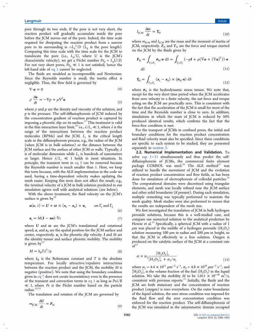
pore through its two ends. If the pore is not very short, thereaction product will gradually accumulate inside the porebefore the JCM moves out of the pore. Indeed, the time scalerequired for dissipating the reaction product from a narrowpore to its surrounding is ∼Lp2/D (Lp is the pore length).Comparing this time scale with the time scale for the JCM totranslocate the pore (i.e., Lp/U, where U is the JCM’scharacteristic velocity), we get a Peclet number Pep = LpU/D.For not very short pores, Pep ≪ 1 is not satisfied; hence theleft-hand side of eq 1 cannot be neglected.The fluids are modeled as incompressible and Newtonian.
Since the Reynolds number is small, the inertia effect isnegligible. Thus, the flow field is governed by
∇· =u 0 (4)
ρ μ∂∂
= −∇ + ∇uu
tp 2
(5)
where ρ and μ are the density and viscosity of the solution, andp is the pressure. The self-diffusiophoresis of JCM induced bythe concentration gradient of reaction product is captured byimposing a phoretic slip on its surface.31 This treatment is validin the thin interaction layer limit,30 i.e., λ/Lc ≪ 1, where λ is therange of the interactions between the reaction productmolecules (RPMs) and the JCM. Lc is the critical lengthscale in the diffusiophoresis process, e.g., the radius of the JCM(when JCM is in bulk solution) or the distance between theJCM surface and the surface of other JCM or walls. Typically, λis of molecular dimension while Lc is hundreds of nanometersor larger. Hence λ/Lc ≪ 1 holds in most situations. Inprinciple, the transient term in eq 5 can be removed becausethe Reynolds number is much smaller than 1. Here, we keepthis term because, with the ALE implementation in the code weused, having a time-dependent velocity makes updating themesh easier. Keeping this term does not affect the result; e.g.,the terminal velocity of a JCM in bulk solution predicted in oursimulation agrees well with analytical solutions (see below).With the above treatment, the fluid velocity on the JCM’s
surface is given by30
ω= + × − + Γ Γu x U x xt u( , ) ( ) on ands 0 s 1 2(6)
= − ·∇u I nnM c( )s (7)
where U and ω are the JCM’s translational and rotationalspeed, xs and x0 are the spatial position for the JCM surface andcenter, respectively. us is the phoretic slip velocity. I and M arethe identity tensor and surface phoretic mobility. The mobilityis given by10
λ μ=M k T /B2
(8)
where kB is the Boltzmann constant and T is the absolutetemperature. For locally attractive/repulsive interactionsbetween the reaction product and the JCM, the mobility M isnegative (positive). We note that using the boundary conditiongiven in eq 7 does not create inconsistency even in the presenceof the transient and convection terms in eq 1 as long as Peλ/R≪ 1, where Pe is the Peclet number based on the particleradius.30,35
The translation and rotation of the JCM are governed by
=UFm
tddJCM H (9)
ω = TIt
ddJCM H (10)
where mJCM and IJCM are the mass and the moment of inertia ofJCM, respectively. FH and TH are the force and torque exertedon the JCM by the fluids given by
∫ ∫σ μ= · = − + ∇ + ∇ ·Γ ∪Γ Γ ∪Γ
F n I u u nS p
S
d ( ( ( ) ))
d
H HT
1 2 1 2
(11)
∫ σ= − × ·Γ ∪Γ
T x x n S( ) ( ) dH s 0 H1 2 (12)
where σH is the hydrodynamic stress tensor. We note that,except for the very short time period when the JCM acceleratesfrom zero velocity to a finite velocity, the net force and torqueacting on the JCM are practically zero. This is consistent withthe fact that the acceleration of the JCM is small for most of thetime and the Reynolds number is close to zero. In addition,simulations in which the mass of JCM is reduced by 50%produced identical results, which confirms the fact that theforce-free condition is met.For the transport of JCMs in confined pores, the initial and
boundary conditions for the reaction product concentrationand fluid velocity must also be specified. Since these conditionsare specific to each system to be studied, they are presentedseparately in section 3.
2.2. Numerical Implementation and Validation. Tosolve eqs 1−11 simultaneously and thus predict the self-diffusiophoresis of JCMs, the commercial finite elementpackage COMSOL was used.36 The ALE method37 wasutilized to handle the movement of JCM and the evolutionof reaction product concentration and flow fields, as has beendone for simulation of electrophoresis of colloidal particles.38
The computational domains were discretized using triangularelements, and mesh was locally refined near the JCM surfaceand other solid boundaries (if present). During each simulation,multiple remeshing was typically performed to maintain themesh quality. Mesh studies were also performed to ensure thatthe results are independent of the mesh size.We first investigated the translation of JCM in bulk hydrogen
peroxide solutions, because this is a well-studied case, andcompare our numerical solution to the analytical prediction byHowse et al.10 Specifically, a spherical JCM with a radius of 1μm was placed in the middle of a hydrogen peroxide (H2O2)solution measuring 100 μm in radius and 200 μm in height, sothat the JCM is effectively in a free solution. Oxygen isproduced on the catalytic surface of the JCM at a constant rateof10
α αα α
=+
[H O ][H O ] /
v
v2
2 2
2 2 2 1 (13)
where α1 = 4.4 × 1011 μm−2 s−1, α2 = 4.8 × 1010 μm−2 s−1, and[H2O2]v is the volume fraction of the fuel (H2O2) in the liquidsolution. We take the mobility M to be 1.011 × 10−36 m5/s,consistent with previous reports.31 Initially, the fluids and theJCM are both stationary and the concentration of reactionproduct (oxygen) is zero everywhere. On the outer boundariesof the liquid solution, the zero stress condition was imposed forthe fluid flow and the zero concentration condition wasenforced for the reaction product. The self-diffusiophoresis ofthe JCM was simulated in the axisymmetric domain occupied
Langmuir Article
DOI: 10.1021/acs.langmuir.6b01214Langmuir 2016, 32, 5580−5592
5582

by the liquid solution using the aforementioned model. Duringthe simulation, the JCM reaches a steady velocity quickly(before it translates by 0.5 μm). The steady translation velocityfor this problem has been predicted analytically as10
α=UM
D4a (14)
Using the typical properties of O2 and H2O2 solution (DO2= 2
× 10−9m2/s, ρH2O2= 1.05 × 10³ kg/m3, μH2O2
= 1.02 × 10⁻³ Pa·s), we compute the steady translation velocity of a JCM in afree solution. Figure 2 shows that the translation velocitypredicted by our simulation agrees with that predicted by eq 14very well.
Since we will study how confinement affects the dynamics ofJCMs in this work, we next verify that our numericalimplementation is capable of capturing dynamics of particlesunder geometrical confinement. We simulated the passivediffusiophoresis of a noncatalytic sphere inside a cylindricalpore (see Figure 3, inset). Specifically, a sphere with a radius of
Rs is positioned on the axis of a long, cylindrical pore with aradius of Rp and a length of Lp. The no-slip boundary conditionis applied on the pore wall for the fluid velocity. If aconcentration difference of a certain solute, Δc, exists at thepore’s two ends, the sphere migrates along the pore axis viadiffusiophoresis at a speed of39
= Δ − +
− +
⎡
⎣⎢⎢
⎛⎝⎜⎜
⎞⎠⎟⎟
⎛⎝⎜⎜
⎞⎠⎟⎟
⎛⎝⎜⎜
⎞⎠⎟⎟
⎛
⎝⎜⎜⎛⎝⎜⎜
⎞⎠⎟⎟
⎞
⎠⎟⎟⎤
⎦⎥⎥
UM c
LRR
RR
RR
ORR
1 1.290 1.896
1.028
pp
s
p
3
s
p
5
s
p
6
s
p
8
(15)
where M is the diffusiophoresis mobility of the sphere.Physically, as the particle radius Rs approaches Rp, the velocityreduces due to the confinement effects. In our simulations, asphere with Rs = 1 μm was placed in the middle of a cylindricalpore with Rp = 2−20 μm. The length of the pore is Lp = 40Rs,the mobility M is 1.011 × 10−36 m5/s, and Δc is 1 mol/m3.Figure 3 compares the sphere’s normalized translation velocityU* = UpLp/MΔc in pores with various radii as predicted by oursimulations and by eq 15. The good agreement between thecomputed translation velocity and the analytical solutionverifies that the numerical methods and codes used here areaccurate for simulation of diffusiophoresis of particles inconfined geometries.
3. RESULTS AND DISCUSSIONUsing the mathematical model and numerical methodintroduced above, we studied the self-diffusiophoresis ofJCMs under confined conditions. Both the translational androtational dynamics of JCMs were examined to understand howconfinement affects the dynamics of JCMs.
3.1. Translocation of a Single Spherical JCM througha Short Pore. Here, we study the effect of confinement on theself-diffusiophoresis of spherical JCMs along the axis of a shortcylindrical pore. The system consists of a spherical JCM (radiusRJCM, 1 μm; catalytic surface facing downward) and a cylindricalpore (radius, Rp; length, Lp) connected to two large reservoirs(see Figure 4). The diffusiophoresis mobility of the JCM, M, is1.011 × 10−36 m5/s. The rate of reaction production generatedon the JCM’s catalytic surface is 0.05 mol/m2·s. At t < 0, thecenter of the JCM is fixed at a distance of RJCM from the pore’sentrance. Fluids inside the system are at rest and free ofreaction product. Note that, since the diffusion length of thereaction product per unit time is far larger than the distancefrom the JCM to the confining walls, the flow and reactionproduct concentration fields near the JCM positioned at poreentrance reach steady state at a time scale much shorter thanthe time scale associated with their diffusiophoresis through thepore. Hence, the initial conditions barely affect the transport ofJCM. At t = 0, the JCMs start moving by self-diffusiophoresis.The reservoir boundaries were treated as free of hydrodynamicstress and reaction products. The no-slip and no-flux boundaryconditions were enforced on the pore walls. In principle, therecan exist phoretic slips on the pore wall due to theconcentration gradient of the reaction products. Dependingon the interactions between reaction product and pore wall andthe local reaction product concentration gradient, such aphoretic slip can be in the same or opposite direction of theJCM’s diffusiophoresis. This can lead to rich JCM transport
Figure 2. Diffusiophoresis velocity of a single JCM in bulk hydrogenperoxide solution predicted by analytical model (eq 14) and numericalsimulations.
Figure 3. Passive diffusiophoresis velocity of a sphere in a long porecomputed using simulations and using the analytical solution (eq 15).Inset is a schematic of the simulation model.
Langmuir Article
DOI: 10.1021/acs.langmuir.6b01214Langmuir 2016, 32, 5580−5592
5583

behavior in the pore, similar to the situation when electro-phoresis of particles in pores is affected by electroosmotic flowsnear walls.39,40 Here, in order to focus on the confinementeffect, we neglect these complications and assume that thediffusiophoretic slips on the pore wall are fully suppressed (e.g.,by polymer coating).41
To study effects of confinement on JCM translation, we varyboth Rp and Lp systematically. We first examine the effect of Rpby varying βW = Rp/RJCM from 1.6 to 6, while keeping the porelength constant at βL = Lp/RJCM = 20. Hereafter, all variablesare presented in dimensionless form. The velocity of the JCMU* is scaled by the JCM’s velocity in unbounded free solution,UJCM
∞ , and the JCM traveling distance Z* is scaled by Lt = Lp +RJCM, i.e., the distance traveled by the JCM when it fullytranslocates the pore (see Figure 4). With these choices ofreference length and velocity, the dimensionless time isconstructed as τ = tUJCM
∞ /Lt, where Lt/UJCM∞ represents the
time for a JCM to travel Lt in free solution. Figure 5a shows thetranslation velocity of the JCM through various pores as afunction of time. In all cases, after self-diffusiophoresis isenabled (τ = 0), the JCM quickly achieves a velocity close to itssteady velocity in free solution (i.e., U* = 1). In a moderatelynarrow pore (βW = 2), the evolution of the JCM’s velocityshows three distinct stages (see Figure 5a,b): when the JCMstarts to enter the pore, its velocity decreases, reaching aminimum at τ < 0.25; as the JCM moves deeper inside the poreand toward the exit, its velocity increases and reaches amaximum before exiting the pore; as the JCM reaches the exit(marked using plus signs in Figure 5b), its velocity decreasesrapidly toward its steady-state velocity in the free solution. Tounderstand such a nonmonotonic evolution of the JCMvelocity, we note that the diffusiophoresis of JCM is governedby the phoretic slip on its surface, which in turn depends on thegradient of the RPM along its surface. Since the latter gradientdepends qualitatively on the difference of the RPMconcentrations Δcsn = cs − cn at the catalytic south pole csand uncoated north pole cn (see Figure 4), we now examine this
difference and its evolution with time in Figure 6. Note, in allfigures, Δcsn is normalized by the difference of the productconcentrations at the south and north poles of a JCM in freesolution, Δcsn∞. The cs and cn are normalized by the productconcentration at the north pole of a JCM in free solution, cn
∞.Figure 6b shows that, for βW = 2, when the JCM just enters
the pore, Δcsn* decreases, which is consistent with the gradualdecrease of U* observed in Figure 5a. As the JCM moves intothe pore, the concentrations of reaction product at both itssouth and north poles increase because the diffusion of theRPMs toward the reservoir is hindered by the pore walls,leading to a buildup of RPMs on the JCM surface (see Figure6a). However, cs* (solid lines) increases slower than cn* (dashedlines). This is because the transport of RPMs away from thesouth pole of a JCM, which faces a large reservoir nearby, ismore efficient than from the north pole, which faces the interior
Figure 4. Schematic of a JCM translocating through a narrow pore.The JCM, with its catalytic surface facing the negative z-direction, isinitially positioned at a distance of RJCM from the pore’s entrance. Thelarge black arrow indicates the swimming direction of the JCM due toself-diffusiophoresis. The cs and cn are the product concentrations atthe south and north poles of JCM, respectively.
Figure 5. Translocation of a JCM through cylindrical pores withdifferent radii but the same length (Lp = 20RJCM). (a) Position of theJCM inside the pore at three time instants. (b, c) Evolution of JCMdimensionless velocity and JCM dimensionless traveling distance asthe JCM “swims” through the pore. The plus signs in (b) mark thetime instants at which the JCM leaves the pore. A JCM completes itstranslocation through the pore when it reaches Z* = 1, and thecorresponding time instant is marked by “×” in (c). Movie 1 in theSupporting Information shows the translocation of a JCM through apore with βW = 1.6.
Langmuir Article
DOI: 10.1021/acs.langmuir.6b01214Langmuir 2016, 32, 5580−5592
5584

of a long pore (see Figure 5a, I). Consequently, Δcsn* decreasesas the JCM moves toward the pore interior (see Figure 6b) andthe self-diffusiophoresis of JCM weakens. In response, JCMslows down. However, as the JCM moves deeper into the pore(see Figure 5a, II), Δcsn* increases because the productmolecules generated on the catalytic surface are confinedmore near the catalytic surface and transported less to theuncoated surface due to the confinement by pore walls.Consequently, the JCM speeds up as shown in Figure 5b.Finally, when the JCM starts to move out of the pore (seeFigure 5a, III), the concentration of reaction products near itssouth pole drops rapidly due to their efficient transport towardthe large reservoir, leading to a rapid decrease of Δcsn* and theJCM velocity toward their values in free solutions. We note thatthe fact that confinement modifies the reaction productconcentration field near JCMs in pores has been reported byTao and Kapral.21 In their work, the accumulation of reactionproduct inside the pore was removed using an artificial schemein which reaction products are converted back to reactantswhen they diffuse far enough away from the catalytic dimer. Assuch, the effect of confinement on reaction productconcentration is much less distinct in their studies.When the pore becomes narrower (βW = 1.6), the effect of
confinement on the transport of RPMs becomes stronger andΔcsn* exhibits a much larger variation as the JCM enters andleaves the pore (see Figure 6b). These variations of Δcsn modifythe translation of JCM through the same physics discussedabove, but the effects are more pronounced; e.g., the maximalspeed of the JCM, which is achieved when the JCM is about toexit the pore, is 2.25 times that in free solutions (see Figure 5b).On the other hand, as the pore becomes wider (βW = 6), the
effect of confinement on JCM dynamics diminishes: thevelocity of the JCM changes only slightly as the JCM passesthrough the pore and the JCM velocity and the translocationtime are hardly affected by the presence of the pore walls (seeFigure 5b,c).Overall, the translocation of JCMs through the pore is
slowed down rather modestly by the confinement. In fact, theslowdown of self-diffusiophoresis by confinement is weakercompared to that for the particle transport driven by other well-known mechanisms. Figure 7 compares the average speed of
spheres traveling through narrow pores driven by self-diffusiophoresis, external body forces,42 and passive diffusio-phoresis.40 In the latter two cases, the motion of a sphere isinduced by an external body force and an externally imposedconcentration gradient of a certain solute (see the insets ofFigure 7), respectively. For the self-diffusiophoresis of a spherethrough a short pore, its average speed is defined as the meanvelocity during its translocation through the pore. For transportby the latter two mechanisms, the pore is infinitely long andStokes flow is assumed; for self-diffusiophoresis, the pore lengthis fixed at 20RJCM. The comparison of the transport of particlesdriven by different mechanisms is complicated by the fact thatthe mean velocity of a JCM driven by self-diffusiophoresis isobtained in a finite-length pore, which includes the “entrance”and “end” effects. Nevertheless, since these effects tend tocancel each other (cf. Figure 5a), the above comparison can stilllead to useful insight on how confinement affects the transportof particles by different mechanisms.Figure 7 shows that, for βW = 2, the velocity of a sphere
driven by external force is 82% smaller than that in freesolutions. Such a significant slowdown is caused by theenhanced hydrodynamic drag in narrow pores.42 For thepassive diffusiophoresis in the same pore, its speed decreasesless significantly, by 11%. This is because, for a given externallyimposed concentration gradient of solutes (usually imposed at adistance away from the sphere), the solute concentrationgradient near the sphere is greatly enhanced when it is confinedinside a pore. This enhances the phoretic driving force andcounteracts the enhanced hydrodynamic drag caused byconfinement.43 For self-diffusiophoresis of a JCM in the same
Figure 6. Reaction product concentrations at the south and northpoles of the JCM. The evolution of cs* (solid lines) and cn* (dashedlines) (a), and the difference of reaction product concentrations at thesouth and north poles of the JCM (b) as the JCM “swims” through thepore.
Figure 7. Comparison of the average speed of sphere through poresdriven by different mechanisms as a function of confinement βW = Rp/Rs (Rp and Rs are the radii of the pore and sphere, respectively). Foreach transport mechanism, the average speed of the sphere inside apore Up is scaled using the sphere’s speed in the free solution, U∞.Insets are the sketches of different particle transport mechanisms.
Langmuir Article
DOI: 10.1021/acs.langmuir.6b01214Langmuir 2016, 32, 5580−5592
5585

pore (βW = 2), the slowdown by confinement is even weaker(∼4%). This can be understood as follows. First, since theRPMs are generated on the JCM’s catalytic surface and theymust diffuse toward the two ends of the pore; theirconcentration near the JCM’s catalytic surface increases whenthe pore size reduces. This tends to enhance the concentrationgradient of reaction product on the JCM’s surface more greatlycompared to the situation in passive diffusiophoresis. Second,for the translocation of JCM through a short pore by self-diffusiophoresis, the JCM travels faster than in free solutionwhen it approaches the pore’s exit, which partially compensatesthe slowdown of JCM near the pore entrance (see Figure 5b).Since this feature is absent for passive diffusiophoresis of asphere in a long pore, the overall slowdown is weaker for self-diffusiophoresis. Finally, the fact that particle−wall hydro-dynamic interactions have a longer range in force-drivenparticle transport than those in classical and self-diffusiopho-resis also contributes to the stronger sensitivity of force-drivenparticles to the confinement by pore walls. Figure 7 also showsthat, when a pore becomes very narrow (e.g., βW = 1.5), theaverage speed of particle transport by self-diffusiophoresisbecomes similar to that by passive diffusiophoresis. This islikely because, for very narrow pores, the pore entrance greatlyslows down the JCM as it enters the pore (see Figure 5b),hence the JCM takes longer time to translocate the pores. Onthe other hand, the passive diffusiophoresis of particle ismeasured inside infinitely long pores and, therefore, is notaffected by such an entrance effect. From the above discussions,it is clear that the self-diffusiophoresis of JCMs in confinedgeometries exhibits interesting new features compared to otherforms of particle transport in similar geometries. Identifyingand understanding these features are useful for improving the
performance of microsystems in which self-diffusiophoresis isused for particle transport.We next examine the effect of pore length Lp on the JCM
translocation through pores by varying βL = Lp/RJCM between10 and 30, while fixing βW = 2. Figure 8a shows that, in allpores, the three stages of JCM translocation, during which theJCM velocity varies nonmonotonically, are still observed. Inlonger pores, the initial slowdown of JCM is more significant,consistent with the greater decrease of Δcsn* in the longer poresduring this stage (see Figure 8d). The latter is mostly caused bythe fact that, in longer pores, RPMs build up more easily nearthe north pole of the JCM (see Figure 8b), which faces theinterior of the pore. In longer pores, the increase of the JCMspeed once it is deep inside the pore is also more obvious. Forexample, the maximal velocity of the JCM inside a poreincreases by 15% when βL increases from 10 to 30. This isbecause, in longer pores, the buildup of the RPMs near thecatalytic surface is more significant due to the less effectivetransport of these molecules from these pores to reservoir andthe longer time the JCM spends inside these pores. Overall,Figure 8c shows that, in moderately narrow pores (βL = 2), theaverage speed of the JCM decreases only slightly as the porebecomes longer: as βL increases from 10 to 30, the time forJCM to translocate through the pore increases by 8%, i.e., theaverage speed of the JCM inside the pore decreases by 8%.We also studied how the reaction rate on the JCM’s catalytic
surface affects its translocation through pores (see Figure S1 inthe Supporting Information). We found that, for a given pore,the average translocation velocity roughly increases linearlywith the reaction rate. Equation 14 shows that, in bulksolutions, the velocity of a JCM also increases linearly with thereaction rate. The fact that confinement does not greatly
Figure 8. Translocation of a JCM through cylindrical pores with different lengths but the same radius (Rp = 2RJCM). The evolution of JCMdimensionless velocity (a), the cs* (solid lines) and cn* (dashed lines) (b), JCM dimensionless position (c), and the difference of reaction productconcentrations at the south and north poles of the JCM (d) as the JCM “swims” through the pore.
Langmuir Article
DOI: 10.1021/acs.langmuir.6b01214Langmuir 2016, 32, 5580−5592
5586

change the effect of reaction rate on the JCM movement islikely because the effect of confinement on the transport ofreaction product is similar regardless of the reaction rate.The above discussion revealed that the translocation of JCMs
through pores is governed by the complex interplay betweenhydrodynamics in confinement and the transport of reactionproducts near the JCM and inside the pores. The weakdependence of the JCM’s average translocation speed on thepore size and length is due to the rather strong cancellationeffects of these processes. From an application perspective, thefact that a JCM’s average translocation speed is affected weaklyby confinement of pore walls helps simplify its design fortransport in pores because its velocity in free solutions can beused to estimate its translocation. It should, however, becautioned that these results are obtained under the conditionthat the reaction rate is a constant; i.e., the effect ofconsumption of fuel on the reaction rate is assumed to besmall. As discussed earlier, this assumption is reasonable whenDa = sL/DfCf ≪ 1. Because the pore length is the most relevantlength scale for fuel transport inside a pore, it follows that theabove results on JCM dynamics in pores hold for pores withpore length smaller than DfCf/s. For much longer pores, theeffects of fuel transport must be considered in analyzing theJCM dynamics.3.2. Translocation of a Pair of Spherical JCMs through
a Short Pore. In practical applications and many recentexperiments, many JCMs could coexist in the system.6,44,45
Because of the “crowding” of JCMs in these systems, thedynamics of individual JCMs can be affected greatly by theinteractions between the JCMs. Here we consider thetranslocation of a pair of JCMs through a cylindrical pore to
gain insights on how interactions between JCMs affect theirtransport in confinement. Specifically, two JCMs (RJCM = 1μm) are positioned near the entrance of a short cylindrical pore(Rp = 2RJCM; Lp = 20RJCM), with their axes aligned with thepore’s axis. The pore is open to large liquid solution reservoirs(length, 50RJCM; radius, 50RJCM) at both ends. The distancebetween the center of the JCM closer to the pore and the poreentrance is RJCM. The separation between the JCMs is 2RJCM,and the catalytic surfaces of both JCMs are facing downward(see Figure 9a, inset). The interactions between JCMs arerelatively strong under these conditions, but we verified inseparate simulations that varying the distance between JCMsdoes not qualitatively change the results. The initial conditionsand boundary conditions are similar to those in section 3.1; e.g.,the JCMs are at rest for τ < 0 and allowed to move by self-diffusiophoresis at τ = 0.Figure 9a shows the evolution of the velocity of the two
JCMs (hereafter, the JCM entering the pore first is termed thefront JCM, while the other JCM is termed the back JCM) asthey pass through the pore. The evolution of the velocity ofboth JCMs exhibits the same trend found during thetranslocation of single JCMs through the pore (dashed linesin Figure 9); i.e., as a JCM passes through the pore, theslowdown−speedup−slowdown cycle of its velocity ispreserved qualitatively. There are, however, quantitativedifferences between the dynamics of the JCMs studied hereand in Figure 5a. Compared to the situation when a single JCMpasses through the pore, for the front JCM, its initial slowdownterminates at an earlier time, its subsequent speedup is moresignificant (Figure 9a), and its translocation time is ∼12%shorter (Figure 9b). For the back JCM, it slows down much
Figure 9. Translocation of a pair of JCMs through a short pore. (a, b) Evolution of the velocity (a) and the position (b) of each JCM as a function oftime. The dashed line is the result of single JCM translocating through the same short pore from Figure 5. A JCM completes its translocationthrough the pore when it reaches Z* = 1. (c) Reaction product concentration field at τ = 0.9, when the front JCM is about to exit the pore (theJCMs are marked by the white circles). The black circles denote the initial positions of the JCMs. The arrows denote the slip velocity on the JCMs’surface. Movie 2 in the Supporting Information shows the translocation process.
Langmuir Article
DOI: 10.1021/acs.langmuir.6b01214Langmuir 2016, 32, 5580−5592
5587

more greatly as it enters the pore and becomes nearly stalled;while its speed does increase later and nearly reaches themaximal velocity of a single JCM passing through the samepore (Figure 9a), its net translocation time is 50% longer thanthat of a single JCM passing through the pore (Figure 9b).Overall, pairing of JCMs affects the translocation of the frontand the back JCMs very differently: it weakly accelerates thetranslocation of the front JCM, but greatly slows down thetranslocation of the back JCM.The different behaviors of JCMs passing through a pore as
pairs and as singlets and the different effects of JCM pairing onthe translocation of the front and back JCMs originate mostlyfrom the “chemical interactions” between a pair of JCMstranslocating a pore. These chemical interactions originate fromthe modification of the slip velocity and viscous stress on theJCM’s surface due to changes in the reaction productconcentration field near the JCM. They have been previouslyshown to affect the dynamics of a pair of “active” particles or aJCM near confining walls.3,16,23−29,46 In light of these works, weanalyze the reaction product concentration nearby in thesystem. Pairing of JCMs inside a narrow pore leads to aconcentration field of the reaction product shown in Figure 9c.Because of pairing, the concentration of RPM near the catalyticsurface of the front JCM is enhanced greatly, which enhancesthe strength of diffusiophoresis of the front JCM (see thephoretic slip velocity us indicated by the black arrows in Figure9c). Meanwhile, the concentration of RPM near the non-catalytic surface of the back JCM is elevated by the pairing ofJCMs, which weakens the phoretic slip on the surface of theback JCM and thus slows down its translocation. The “chemicalinteractions” between adjacent JCMs confined in narrow poresmay be useful in designing a complex system for particulatetransport; e.g., they may be harnessed to accelerate or block themotion of a certain group of particles, hence being useful forlocal control of system behaviors.3.3. Rotational Dynamics of Circular JCMs near and in
Short Pores. In free solutions, self-diffusiophoresis drives aJCM to move in the direction defined by the vector pointingfrom the apex of its catalytic surface to the apex of itsnoncatalytic surface. For convenience, we can identify thisvector as the “phoretic axis” of the JCM (identified as rsn inFigure 10). In the above discussions, all spherical JCMs arepositioned with their phoretic axes coinciding with the pore’saxis and thus they do not experience rotation. In practice,however, the phoretic axis of JCMs may not be fully alignedwith the pore’s axis, e.g., due to thermal fluctuations or forcesimposed by external magnetic fields.47 Therefore, it isimportant to understand how JCMs’ orientation affects theirtransport into and through pores. Here, we study the transportof single JCMs in two scenarios in which their axes are notalways fully aligned with the pore axis. Since simulation ofparticle transport in confined space, in which a particle canapproach the pore wall closely, is expensive, all simulations areperformed in two-dimensional spaces (i.e., JCMs are circulardisks) to explore the JCMs’ translation and rotational dynamics.We note that prior studies of the electrophoresis of chargedparticles in a microchannel revealed that the rotation ofparticles driven by phoretic effects can be indeed captured quitewell in two-dimensional simulations.48
3.3.1. A JCM Entering a Pore. In this first scenario, a circularJCM is initially positioned at the entrance of a pore with itscenter on the pore’s axis and its phoretic axis forming aninclination angle θ0 with the pore’s axis (identified as rc in
Figure 10). The JCM has a radius of RJCM = 1 μm, and the porehas a width of 6RJCM and a length of 50RJCM. Two largereservoirs are included at the pore’s two ends. The pore wallsare treated as no-slip and nonpermeable surfaces. At τ = 0, theentire system is free of RPM and both the fluids and the JCMhave zero velocity. At τ > 0, the JCM is allowed to move by self-diffusiophoresis.Figure 10 shows the trajectories of the JCMs with different
initial inclination angles θ0. We observed the dynamics of theJCM greatly depends on θ0. For small θ0 (e.g., θ0 = 45°),initially, the JCM mostly moves toward the right pore wall withlittle rotation. Once it is close to the pore’s right wall, the JCMrotates rapidly in the counterclockwise direction and turns intothe pore and its phoretic axis becomes aligned with the pore’saxis. The JCM’s motion is somewhat similar to the “reflection”and “skimming” of JCMs near semi-infinite walls when theyapproach the wall at some inclination angles.23,24,26,27,46 Forlarge θ0 (e.g., θ0 = 60° and 90°), the initial stage of JCMmovement is similar to that for small θ0. However, by the timethe JCM is close to the right pore wall, the JCM rotates in theclockwise direction. This rotation causes the JCM’s phoreticaxis to become less aligned with the pore’s axis, and the JCMeither collides with the pore entrance (θ0 = 60°) or swimstoward the reservoir (θ0 = 90°).To understand these observations, we note that the rotation
of a JCM is determined by the net torque acting on it, which inturn depends on the distribution of the viscous stress on itssurface (see eq 12). The viscous stress at any point on a JCM’ssurface scales as σ μ∼ u /s t , where ut is the local fluid velocitytangential to the JCM’s surface and is the length over whichthe fluid velocity decays to zero as one moves away from theJCM’s surface. For a JCM near pore walls, can be taken as thedistance from the JCM surface to the nearest wall, Lsw. Giventhat the velocity of fluids on the JCM surface is usuallydominated by the phoretic slip velocity us, we have σs ∼ μus/Lsw. The part of a JCM’s surface on which the phoretic slipvelocity us points in the counterclockwise (clockwise) directionwith respect to its center experiences a local stress in theclockwise (counterclockwise) direction, and is defined as Γc(Γcc) and labeled by green (yellow) curves in Figure 11. Asreported in previous studies, the local stress on JCM’s surface is
Figure 10. Trajectories of JCMs with different initial inclination anglesθ0 near a pore’s entrance. The JCM’s center is initially positioned at z= 0. For small θ0, the JCM can rotate toward the pore interior andswim into the pore. For large θ0, the JCM either collides with the porewall or swim away from the pore. Movie 3 in the SupportingInformation shows the trajectory of the JCM with θ0 = 90°.
Langmuir Article
DOI: 10.1021/acs.langmuir.6b01214Langmuir 2016, 32, 5580−5592
5588

controlled by two effects: the chemical effect and thehydrodynamic effect.23,24,26,46 The chemical effect refers tothe fact that the viscous stress depends on us, which isdetermined by the tangential gradient of chemical species (inour case, the product of the catalytic reactions) on the JCM’ssurface as shown by eq 7. The chemical effect depends stronglyon the transport of the reaction products, which is affected bythe confinement by pore walls. The hydrodynamic effect refersto the fact that, for a given us, the local viscous stress dependson the fluid flow near the JCM’s surface, or roughly the distancefrom the JCM surface to the nearest pore wall as pointed outabove.Both hydrodynamic and chemical effects contribute greatly
to the dependence of a JCM’s rotation on its initial inclinationangle, θ0. For clarity, we first examine purely the hydrodynamic
effect. To this end, we assume that the phoretic slip velocity us(black arrows in Figure 11) on the surface of a JCM is identicalto that when the JCM is located in unbounded free solutionregardless its location and orientation in the system. When aJCM is placed at the entrance of the pore with θ0 = 45°,initially, the JCM swims toward the pore wall with littlerotation. Once the JCM is near the pore wall (e.g., at τ = 0.34,see Figure 11a), the viscous stress σs on the Γcc surface becomeslarger than that on the Γc surface: while the slip velocitydistribution on the Γcc and Γc surface is the same, Lsw is smalleron the Γcc surface than on the Γc because of the smallinclination angle of the JCM. As a result, the net torquegenerated by the viscous stress on the Γcc surface is strongerthan that on the Γc surface, and the JCM rotates in thecounterclockwise direction. We next examine the role ofchemical effects in the rotation of the JCM. To this end, recallthat confinement affects the transport of reaction product nearthe JCM and thus the us distribution on JCM’s surface. InFigure 11b, we plot the real us (black arrows) on the JCM’ssurface at τ = 0.34. We observe that the area of the JCM’ssurface (yellow) on which us points to the clockwise direction islarger than the area of the JCM’s surface (green) on which uspoints to the counterclockwise direction; i.e., Γcc is larger thanΓc. The larger area of Γcc than Γc tends to increase the nettorque exerted on the JCM in the counterclockwise direction,and thus the JCM rotates in the counterclockwise direction andswims deeper into the pore. Overall, the role of hydrodynamicand chemical interactions on the JCM dynamics in the situationexamined here shows clear similarity with that for JCMs nearsemi-infinite walls.For the JCM with an initial inclination angle of θ0 = 60°, we
again first focus on the hydrodynamic effects only. Figure 11cshows the sketch of the JCM at τ = 0.24, in which the slipvelocity us on the JCM’s surface is taken as that for JCM in freesolution. In this case, because of its large θ0, most of the Γccsurface faces the reservoir instead of the right pore wall andmost of the Γc surface faces the pore interior, which are in sharpcontrast to the situation for the JCM with θ0 = 45° (see Figure11a). As a result, the Lsw for the majority of the Γcc surface islarger than that for the majority of the Γc surface. Hence theviscous stress is stronger on the Γc surface than on the Γccsurface, and the resulting net torque drives the JCM to rotate in
Figure 11. Distribution of the phoretic slip velocity us on the surface ofJCMs when they approach the pore wall. Each JCM is originally placedat the pore entrance with an inclination angle θ0 as shown in Figure 10.The surface on which us points in the clockwise (counterclockwise)direction with respect to the JCM center and the local viscous stresscauses a counterclockwise (clockwise) torque is defined as Γcc (Γc). In(a) and (c), us is taken, hypothetically, to be that for JCM in the freesolution to isolate the hydrodynamic effect on JCM rotation. In (b)and (d), the real us determined in simulations is shown to helpdelineate the chemical effects on JCM rotation.
Figure 12. Self-alignment behavior of JCM swimming inside a pore. The JCM was initially placed near the pore entrance with phoretic axis fullyaligned with the pore axis. An external, clockwise torque was applied on the JCM during τ = 0.34−0.52 to rotate the JCM in the clockwise direction.(a, b) Trajectory (a) and inclination angle (b) of the JCM as a function of time. (c) Distribution of the reaction product near the JCM at τ = 0.87.The black arrows denote the phoretic slip velocities on the JCM’s surface.
Langmuir Article
DOI: 10.1021/acs.langmuir.6b01214Langmuir 2016, 32, 5580−5592
5589

the clockwise direction. We further consider the chemical effectby considering the real phoretic slip velocity us on the JCMsurface (see Figure 11d). We observe that, compared to thoseshown in Figure 10c, the area of the Γc surface facing the poreinterior/wall and the area of the Γcc surface facing the reservoirboth increase. Consequently, the Lsw on the Γcc surfaceincreases, while the Lsw on the Γc surface decreases. Thesechanges enhance (reduce) the viscous stress on the Γc (Γcc)surface and increase the net torque acting on the JCM in theclockwise direction. Hence, the chemical effect furtherenhances the clockwise rotation of the JCM.For θ0 = 90°, the mechanism of the rotational motion of
JCM is similar to that for θ0 = 60°. The imbalance of stressdistribution causes net, clockwise torque acting on the JCM anddrives it to rotate in the clockwise direction. However, becauseof the larger initial inclination angle, the JCM swims toward thereservoir instead of colliding with the pore wall.3.3.2. A JCM Swimming Inside a Pore. In this second
scenario, we study how a JCM inside a pore rotates when itsphoretic axis becomes misaligned with the pore axis. As shownin Figure 12a, initially a JCM swims toward a pore entrancewith its phoretic axis fully aligned with the pore axis. At τ =0.34, when the JCM is inside the pore, an external torque isapplied on the JCM for 1 s, forcing it to rotate in the clockwisedirection. At τ = 0.52, the inclination angle of the JCM reaches40°. The external torque is then removed and the JCM swimssolely by self-diffusiophoresis. This problem mimics thesituation in which the JCM become misaligned with the poreaxis due to reasons such as thermal fluctuations. The size of theJCM, the pore, and the reservoir are the same as those in thescenario 1.Figure 12 shows the trajectory of the JCM and its inclination
angle as a function of time. The JCM exhibits a self-alignmentbehavior after the external torque was removed: (1) it movesaway from the right pore wall and its inclination angledecreases; (2) eventually, the JCM becomes centered across thepore with its phoretic axis aligned with the pore axis. The firstobservation is similar to that observed when a JCM approachesan open, planar wall with its phoretic axis initially forming anangle less than 90°.23,24 This self-alignment behavior is a resultof the combined chemical and hydrodynamic effects. When theJCM deviates from the pore axis and approaches the right porewall as shown in Figure 12a, the distance between the JCM’ssurface facing the right wall decreases, and hydrodynamicseffects cause the viscous stress σs ∼ μus/Lsw on this surface toincrease. Meanwhile, the phoretic slip velocity on the JCM’ssurface facing the right wall increases due to chemical effects,and thus enhances the viscous stress on this surface. Theincreased viscous stress on the JCM’s surface facing the rightwall leads to a net counterclockwise torque acting on the JCM.Such a net torque drives the JCM to rotate in thecounterclockwise direction so that its phoretic axis becomesmore aligned with the pore axis. Moreover, when the JCM isclose to the wall and rotating, it generates a high concentrationzone for the reaction product near the wall (see Figure 12c).Such a high concentration zone triggers the horizontaldiffusiophoresis of the JCM toward the pore center. Becauseof the rotation and horizontal movements, the JCM tends toswim away from the pore wall and thus exhibit the self-alignment behavior shown in Figure 12a,b.The JCM’s off-axis movement shown in Figure 12 bears
some similarities with the off-axis motion (e.g., swinging andtumbling) of squirmers confined in pores.49,50 Similar to the
off-axis motion of JCMs, the modification of the viscous stresson the squirmer’s surface as it moves toward the pore walls isessential for such motion.49,50 The JCM in our study does notexhibit periodic motion such as swinging (i.e., approachingtoward and departing from the pore axis periodically) butmoves toward and then resides on the pore axis. This differenceoriginates from the modification of the surface slip velocity bychemical effects, which plays an important role in JCMdynamics in narrow pores, and is not included in the squirmermodels.
4. CONCLUSIONSThe translational and rotational dynamics of JCMs in confinedgeometries driven by self-diffusiophoresis were studied usingdirect numerical simulations. Our simulations revealed thatJCMs can exhibit rich dynamic behavior under confinedconditions. For the translocation of a single spherical JCMthrough a short cylindrical pore, while the JCM is slowed downby the pore on average, the speed of the JCM can exceed that infree solutions when the JCM approaches the pore exit. Theoverall slowdown of self-diffusiophoresis becomes moreobvious when the pore size reduces, but its dependence onthe pore size is much weaker than the transport of particlesdriven by external force or externally imposed concentrationgradients. For the translocation of a pair of JCMs through apore, when both of their catalytic surfaces are facing the bottomreservoir direction, the front JCM speeds up but the back JCMslows down. For a circular JCM near a pore entrance and withits phoretic axis not aligned with the pore axis, the JCM canenter the pore and its phoretic axis becomes fully aligned withthe pore axis if its initial inclination angle is small. Otherwise,the JCM either collides with the pore entrance or moves awayinto the reservoir. For a JCM already inside a pore, self-diffusiophoresis can align the JCM’s phoretic axis with the poreaxis and drive it toward the pore center for the parametersconsidered here.Analyses showed that these rich behaviors have both
hydrodynamic and chemical origins. In particular, themodification of the chemical species concentrations surround-ing a JCM by wall confinement and its neighboring JCMs,which can be called “chemical effect”, plays a key role indetermining the translation and rotation of the JCMs. Inordinary particulate transport problems, chemical species in thesolution and their transport have little or no impact on theparticulate transport. In the self-diffusiophoresis of JCMs,however, chemical effects become important because thegradient of chemical species on their surface impacts thephoretic slip velocity on the surface. These effects, alreadyidentified in studies of JCM dynamics near semi-infinite walls,are especially significant when the confinement is severe (e.g.,when a JCM is inside a narrow channel21) or when JCMsapproach each other closely.16,28,29 Given these situations areincreasingly encountered in the applications of JCMs, chemicaleffects should be taken into account in the design and operationof JCMs in these applications.While our simulations captured the key physics of self-
diffusiophoresis of JCMs, some other interesting physics are notconsidered. For instance, the effect of fuel transport on JCMdynamics is neglected. Likewise, possible diffusioosmotic flowsinduced by the charges on JCM/pore walls as well as thegradient of reaction product concentration on the pore wall areneglected. These effects merit additional exploration in futurestudies.
Langmuir Article
DOI: 10.1021/acs.langmuir.6b01214Langmuir 2016, 32, 5580−5592
5590

■ ASSOCIATED CONTENT*S Supporting InformationThe Supporting Information is available free of charge on theACS Publications website at DOI: 10.1021/acs.lang-muir.6b01214.
Effects of reaction rate on the translocation of a singleJCM through a pore (PDF)Translocation of a single JCM through a pore (AVI)Translocation of a pair of JCMs through a pore (AVI)Trajectory of a single JCM near the entrance of a pore(AVI)
■ AUTHOR INFORMATIONCorresponding Author*E-mail: [email protected]. Web: http://www.me.vt.edu/ruiqiao.NotesThe authors declare no competing financial interest.
■ ACKNOWLEDGMENTSThe authors gratefully acknowledge support by the NationalScience Foundation (ECCS-1303134 and ECCS-1464146).
■ REFERENCES(1) Ismagilov, R. F.; Schwartz, A.; Bowden, N.; Whitesides, G. M.Autonomous Movement and Self-Assembly. Angew. Chem., Int. Ed.2002, 41, 652−654.(2) Paxton, W. F.; Kistler, K. C.; Olmeda, C. C.; Sen, A.; St. Angelo,S. K.; Cao, Y. Y.; Mallouk, T. E.; Lammert, P. E.; Crespi, V. H.Catalytic Nanomotors: Autonomous Movement of Striped Nanorods.J. Am. Chem. Soc. 2004, 126, 13424−13431.(3) Kapral, R. Perspective: Nanomotors without Moving Parts ThatPropel Phemselves in Solution. J. Chem. Phys. 2013, 138, 020901.(4) Ebbens, S. J.; Howse, J. R. In Pursuit of Propulsion at theNanoscale. Soft Matter 2010, 6, 726−738.(5) Kolmakov, G. V.; Yashin, V. V.; Levitan, S. P.; Balazs, A. C.Designing Self-Propelled Microcapsules for Pick-up and Delivery ofMicroscopic Cargo. Soft Matter 2011, 7, 3168−3176.(6) Baraban, L.; Tasinkevych, M.; Popescu, M. N.; Sanchez, S.;Dietrich, S.; Schmidt, O. G. Transport of Cargo by Catalytic JanusMicro-Motors. Soft Matter 2012, 8, 48−52.(7) Fukuyama, T.; Fuke, A.; Mochizuki, M.; Kamei, K.-i.; Maeda, Y.T. Directing and Boosting of Cell Migration by the Entropic ForceGradient in Polymer Solution. Langmuir 2015, 31, 12567−12572.(8) Zhang, Z.; Zhao, A.; Wang, F.; Ren, J.; Qu, X. Design a PlasmonicMicromotor for Enhanced Photo-Remediation of Polluted AnaerobicStagnant Waters. Chem. Commun. 2016, 52, 5550−5553.(9) Mou, F.; Chen, C.; Zhong, Q.; Yin, Y.; Ma, H.; Guan, J.Autonomous Motion and Temperature-Controlled Drug Delivery ofMg/Pt-Poly (N-Isopropylacrylamide) Janus Micromotors Driven bySimulated Body Fluid and Blood Plasma. ACS Appl. Mater. Interfaces2014, 6, 9897−9903.(10) Howse, J. R.; Jones, R. A. L.; Ryan, A. J.; Gough, T.; Vafabakhsh,R.; Golestanian, R. Self-Motile Colloidal Particles: From DirectedPropulsion to Random Walk. Phys. Rev. Lett. 2007, 99, 048102.(11) Anderson, J. L. Colloid Transport by Interfacial Forces. Annu.Rev. Fluid Mech. 1989, 21, 61−99.(12) Moran, J. L.; Posner, J. D.; Wheat, P. M. Locomotion ofElectrocatalytic Nanomotors Due to Reaction Induced ChargeAutoelectrophoresis. Phys. Rev. E 2010, 81, 065302.(13) Solovev, A. A.; Mei, Y. F.; Urena, E. B.; Huang, G. S.; Schmidt,O. G. Catalytic Microtubular Jet Engines Self-Propelled byAccumulated Gas Bubbles. Small 2009, 5, 1688−1692.(14) Gao, W.; Uygun, A.; Wang, J. Hydrogen-Bubble-Propelled Zinc-Based Microrockets in Strongly Acidic Media. J. Am. Chem. Soc. 2012,134, 897−900.
(15) Manjare, M. T.; Yang, F.; Qiao, R.; Zhao, Y. Marangoni FlowInduced Collective Motion of Catalytic Micromotors. J. Phys. Chem. C2015, 119, 28361−28367.(16) Reigh, S. Y.; Kapral, R. Catalytic Dimer Nanomotors:Continuum Theory and Microscopic Dynamics. Soft Matter 2015,11, 3149−3158.(17) Gao, Y.; Yu, Y. Macrophage Uptake of Janus Particles Dependsupon Janus Balance. Langmuir 2015, 31, 2833−2838.(18) Brown, A.; Poon, W. Ionic Effects in Self-Propelled Pt-CoatedJanus Swimmers. Soft Matter 2014, 10, 4016−4027.(19) Moran, J. L.; Posner, J. D. Role of Solution Conductivity inReaction Induced Charge Auto-Electrophoresis. Phys. Fluids 2014, 26,042001.(20) Popescu, M. N.; Dietrich, S.; Oshanin, G. Confinement Effectson Diffusiophoretic Self-Propellers. J. Chem. Phys. 2009, 130, 194702.(21) Tao, Y. G.; Kapral, R. Swimming Upstream: Self-PropelledNanodimer Motors in a Flow. Soft Matter 2010, 6, 756−761.(22) Yang, M. C.; Wysocki, A.; Ripoll, M. Hydrodynamic Simulationsof Self-Phoretic Microswimmers. Soft Matter 2014, 10, 6208−6218.(23) Uspal, W.; Popescu, M. N.; Dietrich, S.; Tasinkevych, M. Self-Propulsion of a Catalytically Active Particle near a Planar Wall: FromReflection to Sliding and Hovering. Soft Matter 2015, 11, 434−438.(24) Ibrahim, Y.; Liverpool, T. B. The Dynamics of a Self-PhoreticJanus Swimmer Near a Wall. Europhys. Lett. 2015, 111, 48008.(25) Kreuter, C.; Siems, U.; Nielaba, P.; Leiderer, P.; Erbe, A.Transport Phenomena and Dynamics of Externally and Self-PropelledColloids in Confined Geometry. Eur. Phys. J.: Spec. Top. 2013, 222,2923−2939.(26) Mozaffari, A.; Sharifi-Mood, N.; Koplik, J.; Maldarelli, C. Self-Diffusiophoretic Colloidal Propulsion Near a Solid Boundary. 2015,arXiv preprint arXiv:1505.07172 .(27) Das, S.; Garg, A.; Campbell, A. I.; Howse, J.; Sen, A.; Velegol,D.; Golestanian, R.; Ebbens, S. J. Boundaries Can Steer Active JanusSpheres. Nat. Commun. 2015, 6, 8999.(28) Popescu, M. N.; Tasinkevych, M.; Dietrich, S. Pulling andPushing a Cargo with a Catalytically Active Carrier. Europhys. Lett.2011, 95, 28004.(29) Sharifi-Mood, N.; Mozaffari, A.; Cordova-Figueroa, U. PairInteraction of Catalytically Active Colloids: From Assembly to Escape.2015, arXiv preprint arXiv:1510.03000 .(30) Michelin, S.; Lauga, E. Phoretic Self-Propulsion at Finite PecletNumbers. J. Fluid Mech. 2014, 747, 572−604.(31) Golestanian, R.; Liverpool, T.; Ajdari, A. Designing PhoreticMicro- and Nano-Swimmers. New J. Phys. 2007, 9, 126.(32) Gao, W.; Pei, A.; Dong, R.; Wang, J. Catalytic Iridium-BasedJanus Micromotors Powered by Ultralow Levels of Chemical Fuels. J.Am. Chem. Soc. 2014, 136, 2276−2279.(33) Ibele, M.; Mallouk, T. E.; Sen, A. Schooling Behavior of Light-Powered Autonomous Micromotors in Water. Angew. Chem., Int. Ed.2009, 48, 3308−3312.(34) Golestanian, R.; Liverpool, T. B.; Ajdari, A. Propulsion of aMolecular Machine by Asymmetric Distribution of Reaction Products.Phys. Rev. Lett. 2005, 94, 220801.(35) Yariv, E.; Michelin, S. Phoretic Self-Propulsion at Large PecletNumbers. J. Fluid Mech. 2015, 768, R1.(36) Comsol, A. COMSOL Multiphysics User’s Guide; versionSeptember 2005.(37) Hu, H. H.; Patankar, N. A.; Zhu, M. Direct NumericalSimulations of Fluid−Solid Systems Using the Arbitrary Lagrangian−Eulerian Technique. J. Comput. Phys. 2001, 169, 427−462.(38) Qian, S.; Ai, Y. Electrokinetic Particle Transport in Micro-/Nanofluidics: Direct Numerical Simulation Analysis; CRC Press: 2012;Vol. 153.(39) Keh, H.; Anderson, J. Boundary Effects on ElectrophoreticMotion of Colloidal Spheres. J. Fluid Mech. 1985, 153, 417−439.(40) Keh, H. J.; Chiou, J. Y. Electrophoresis of a Colloidal Sphere in aCircular Cylindrical Pore. AIChE J. 1996, 42, 1397−1406.(41) Qiao, R.; He, P. Modulation of Electroosmotic Flow by NeutralPolymers. Langmuir 2007, 23, 5810−5816.
Langmuir Article
DOI: 10.1021/acs.langmuir.6b01214Langmuir 2016, 32, 5580−5592
5591

(42) Happel, J.; Brenner, H. Low Reynolds Number Hydrodynamics:With Special Applications to Particulate Media; Springer Science &Business Media: 2012; Vol. 1.(43) Keh, H. J.; Chen, S. B. Electrophoresis of a Colloidal SphereParallel to a Dielectric Plane. J. Fluid Mech. 1988, 194, 377−390.(44) Buttinoni, I.; Bialke, J.; Kummel, F.; Lowen, H.; Bechinger, C.;Speck, T. Dynamical Clustering and Phase Separation in Suspensionsof Self-Propelled Colloidal Particles. Phys. Rev. Lett. 2013, 110, 238301.(45) Theurkauff, I.; Cottin-Bizonne, C.; Palacci, J.; Ybert, C.;Bocquet, L. Dynamic Clustering in Active Colloidal Suspensions withChemical Signaling. Phys. Rev. Lett. 2012, 108, 268303.(46) Simmchen, J.; Katuri, J.; Uspal, W. E.; Popescu, M. N.;Tasinkevych, M.; Sanchez, S. Topographical Pathways Guide ChemicalMicroswimmers. Nat. Commun. 2016, 7, 10598.(47) Kline, T. R.; Paxton, W. F.; Mallouk, T. E.; Sen, A. CatalyticNanomotors: Remote-Controlled Autonomous Movement of StripedMetallic Nanorods. Angew. Chem. 2005, 117, 754−756.(48) Ai, Y.; Park, S.; Zhu, J.; Xuan, X.; Beskok, A.; Qian, S. DCElectrokinetic Particle Transport in an L-Shaped Microchannel.Langmuir 2010, 26, 2937−2944.(49) Zhu, L.; Lauga, E.; Brandt, L. Low-Reynolds-NumberSwimming in a Capillary Tube. J. Fluid Mech. 2013, 726, 285−311.(50) Zottl, A.; Stark, H. Nonlinear Dynamics of a Microswimmer inPoiseuille Flow. Phys. Rev. Lett. 2012, 108, 218104.
Langmuir Article
DOI: 10.1021/acs.langmuir.6b01214Langmuir 2016, 32, 5580−5592
5592