Embed Size (px)
Citation preview
Abstract— Series elastic actuators are frequently modeled
using a conventional lumped mass model which has remained
mostly unchanged since their introduction almost two decades
ago. The lumped model has served well for early development
but more descriptive models are now needed for new actuator
designs and control approaches. In this paper we propose a new
unlumped model specifically for linear series elastic actuators
which uses a rack & pinion conceptualization to intuitively
depict the mechanics of a linear ball screw drive. Results from
hardware experiments are presented and compared to the
predicted simulation results for both the conventional model and
the new unlumped model. The results demonstrate that the new
unlumped model is significantly more representative of the true
actuator dynamics.
I. INTRODUCTION
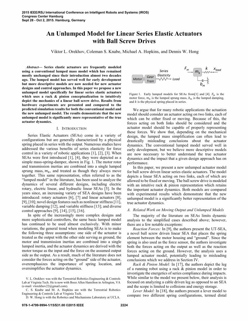
Series Elastic Actuators (SEAs) come in a variety of configurations but are generally characterized by a physical spring placed in series with the output. Numerous studies have addressed the various benefits of series elasticity for force control in a variety of robotic applications [1], [2], [3]. When SEAs were first introduced [1], [4], they were depicted as a simple mass-spring-damper, shown in Fig. 1. The motor rotor and transmission inertias are combined into a single lumped sprung mass, 𝑚𝑘, and treated as though they always move together. This same representation, often referred to as the “lumped model” in the literature, has been used to analyze the dynamics of several different designs, including electric rotary, electric linear, and hydraulic linear SEAs [5]. In the years since, an increasing variety of SEA designs have been introduced: rotary actuators [6], [7] and linear actuators [8], [9], [10]; novel design features such as nonlinear stiffness [11], variable damping [12], and variable stiffness [13]; and diverse control approaches [9], [14], [15], [16].
In spite of the increasingly more complex designs and more sophisticated controllers, the same basic lumped model has continued to be used almost exclusively. With minor variations, the general trend when modeling SEAs is to make the following three assumptions: one side of the actuator is treated as the output with the other side serving as ground, the motor and transmission inertias are combined into a single lumped inertia, and the actuator dynamics are derived with the motor torque as the input and the force on the assumed output side as the output. As a result, much of the literature does not consider the forces acting on the “ground” side of the actuator, overemphasizes the importance of spring location, and oversimplifies the actuator dynamics.
We argue that for many robotic applications the actuation model should consider an actuator acting on two links, each of which can be either fixed or moving. Because of this, the forces acting on both links should be considered and the actuator model should be capable of properly representing these forces. We show that, depending on the mechanical design, the lumped mass simplification can often lead to drastically misleading conclusions about the actuator dynamics. The conventional lumped model served well in early development, but we believe more descriptive models are now necessary to better understand the true actuator dynamics and the impact that a given design approach has on performance.
In this paper, we present a new unlumped actuator model for ball screw driven linear series elastic actuators. The model depicts a linear SEA acting on two links, each of which are allowed to be fixed or moving. The ball screw drive is modeled with an intuitive rack & pinion representation which retains the important actuator dynamics. Both models are compared with experimental results which demonstrate that the new unlumped model is a significantly better representation of the true actuator dynamics.
A. Related Work on Moving Output and Unlumped Models
The majority of the literature on SEAs limits dynamic analysis to the simplified cases described above; however, there are a few notable exceptions:
Reaction Forces: In [9], the authors present the UT-SEA, a novel ball screw driven linear SEA that places the spring element between the motor housing and “ground”. Since the spring is also used as the force sensor, the authors investigate both the forces acting on the output as well as the reaction forces acting on the ground. However, the analysis uses a lumped actuator model, potentially leading to misleading conclusions which we address in Section IV.
Rack & Pinion Model: In [17], the authors depict the leg of a running robot using a rack & pinion model in order to investigate the energetics of series compliance during impacts. While similar to the model we present below, their analysis is focused on analyzing a cable driven leg as opposed to an SEA and the scope is limited to collisions and energy storage.
Lever Model: In [18], the authors present a lever model to compare two different spring configurations, termed distal
An Unlumped Model for Linear Series Elastic Actuators
with Ball Screw Drives
Viktor L. Orekhov, Coleman S. Knabe, Michael A. Hopkins, and Dennis W. Hong
V. L. Orekhov was with the Terrestrial Robotics Engineering & Controls
Lab at Virginia Tech. He is now with Booz Allen Hamilton in Arlington, VA (e-mail: [email protected]).
C. S. Knabe and M. A. Hopkins are with the Terrestrial Robotics
Engineering & Controls Lab at Virginia Tech. D. W. Hong is with the Robotics and Mechanisms Laboratory at UCLA.
Figure 1. Early lumped models for SEAs from[1] and [4]. 𝐹𝑚 is the
motor force, 𝑚𝑘 is the lumped sprung mass, 𝑏𝑚 is the lumped damping,
and 𝑘 is the physical spring placed in series.
2015 IEEE/RSJ International Conference on Intelligent Robots and Systems (IROS)Congress Center HamburgSept 28 - Oct 2, 2015. Hamburg, Germany
978-1-4799-9994-1/15/$31.00 ©2015 IEEE 2224
compliance and proximal compliance. In their model, the fulcrum has a mass which is defined as the transmission housing mass. This could be also be considered an unlumped model; however, the lever conceptualization is less intuitive and can accurately represent only small motions.
B. Model Simplicity vs. Fidelity
Selecting an appropriate model is a critical step in the development of robotic actuators because it is used in making design decisions, evaluating performance, and designing controllers. An effective model can simplify the analysis and provide intuitive insights for a complex system while an oversimplified model can lead to poor design decisions based on misleading analysis. A simpler model is generally preferred as long as it does not neglect any important system dynamics. Fundamentally, the modeling issue is one of properly selecting the inertias in motion which introduces an inherent tradeoff between complexity and fidelity.
C. Ball Screw Driven Linear SEAs
Selecting an appropriate model often depends on the specific application. In this paper, we are addressing the modeling of ball screw driven linear series elastic actuators as they are used in legged robots. Most linear SEAs use ball screw drives because they have high efficiencies, low backlash, and are robust to impacts. However, the rotary-to-linear transmission of a ball screw can be difficult to represent in a way that is intuitive. In this paper, we introduce a rack & pinion representation which is an almost direct analogy for the rotary-to-linear behavior of ball screws.
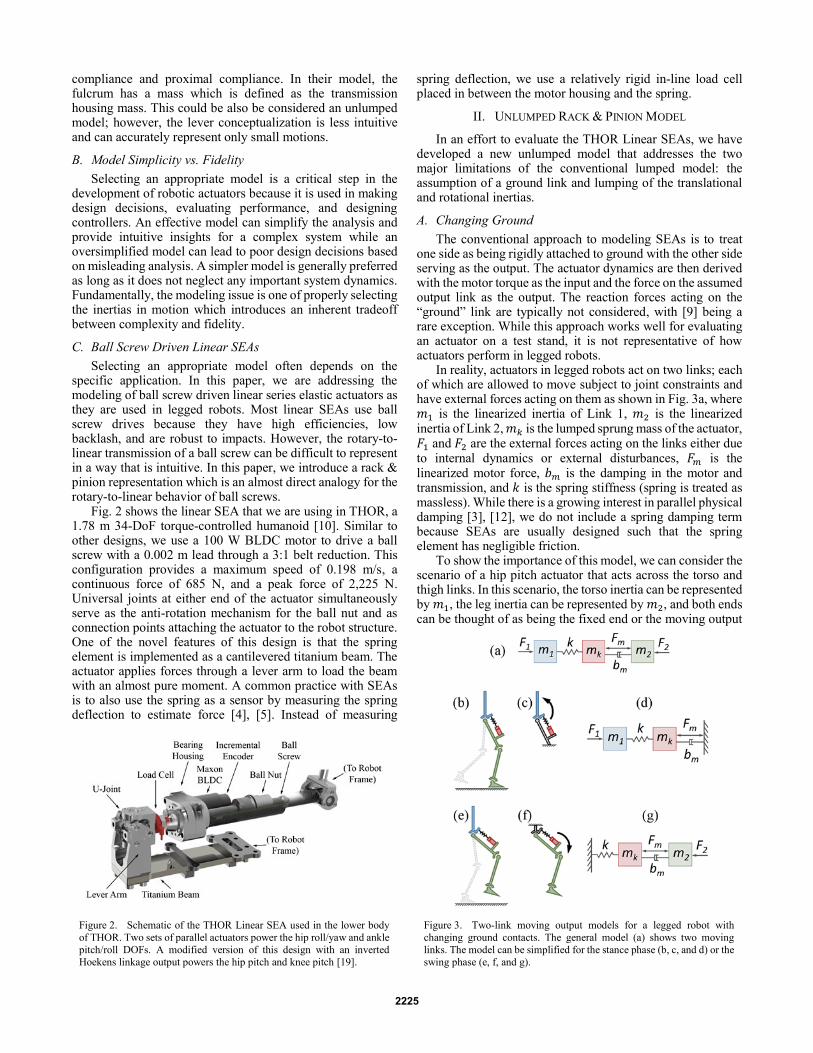
Fig. 2 shows the linear SEA that we are using in THOR, a 1.78 m 34-DoF torque-controlled humanoid [10]. Similar to other designs, we use a 100 W BLDC motor to drive a ball screw with a 0.002 m lead through a 3:1 belt reduction. This configuration provides a maximum speed of 0.198 m/s, a continuous force of 685 N, and a peak force of 2,225 N. Universal joints at either end of the actuator simultaneously serve as the anti-rotation mechanism for the ball nut and as connection points attaching the actuator to the robot structure. One of the novel features of this design is that the spring element is implemented as a cantilevered titanium beam. The actuator applies forces through a lever arm to load the beam with an almost pure moment. A common practice with SEAs is to also use the spring as a sensor by measuring the spring deflection to estimate force [4], [5]. Instead of measuring
spring deflection, we use a relatively rigid in-line load cell placed in between the motor housing and the spring.
II. UNLUMPED RACK & PINION MODEL
In an effort to evaluate the THOR Linear SEAs, we have developed a new unlumped model that addresses the two major limitations of the conventional lumped model: the assumption of a ground link and lumping of the translational and rotational inertias.
A. Changing Ground
The conventional approach to modeling SEAs is to treat one side as being rigidly attached to ground with the other side serving as the output. The actuator dynamics are then derived with the motor torque as the input and the force on the assumed output link as the output. The reaction forces acting on the “ground” link are typically not considered, with [9] being a rare exception. While this approach works well for evaluating an actuator on a test stand, it is not representative of how actuators perform in legged robots.
In reality, actuators in legged robots act on two links; each of which are allowed to move subject to joint constraints and have external forces acting on them as shown in Fig. 3a, where 𝑚1 is the linearized inertia of Link 1, 𝑚2 is the linearized inertia of Link 2, 𝑚𝑘 is the lumped sprung mass of the actuator, 𝐹1 and 𝐹2 are the external forces acting on the links either due to internal dynamics or external disturbances, 𝐹𝑚 is the linearized motor force, 𝑏𝑚 is the damping in the motor and transmission, and 𝑘 is the spring stiffness (spring is treated as massless). While there is a growing interest in parallel physical damping [3], [12], we do not include a spring damping term because SEAs are usually designed such that the spring element has negligible friction.
To show the importance of this model, we can consider the scenario of a hip pitch actuator that acts across the torso and thigh links. In this scenario, the torso inertia can be represented by 𝑚1, the leg inertia can be represented by 𝑚2, and both ends can be thought of as being the fixed end or the moving output
Figure 2. Schematic of the THOR Linear SEA used in the lower body
of THOR. Two sets of parallel actuators power the hip roll/yaw and ankle
pitch/roll DOFs. A modified version of this design with an inverted
Hoekens linkage output powers the hip pitch and knee pitch [19].
Figure 3. Two-link moving output models for a legged robot with
changing ground contacts. The general model (a) shows two moving
links. The model can be simplified for the stance phase (b, c, and d) or the
swing phase (e, f, and g).
2225
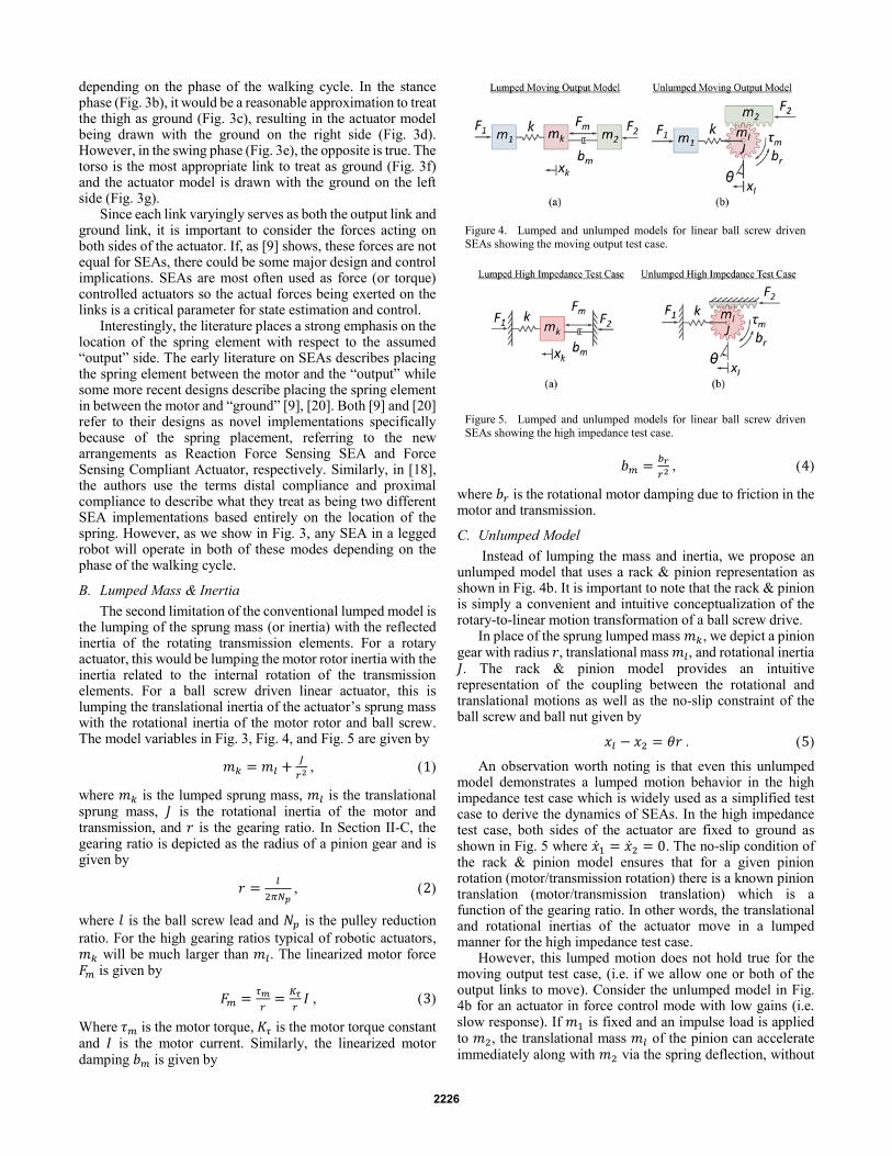
depending on the phase of the walking cycle. In the stance phase (Fig. 3b), it would be a reasonable approximation to treat the thigh as ground (Fig. 3c), resulting in the actuator model being drawn with the ground on the right side (Fig. 3d). However, in the swing phase (Fig. 3e), the opposite is true. The torso is the most appropriate link to treat as ground (Fig. 3f) and the actuator model is drawn with the ground on the left side (Fig. 3g).
Since each link varyingly serves as both the output link and ground link, it is important to consider the forces acting on both sides of the actuator. If, as [9] shows, these forces are not equal for SEAs, there could be some major design and control implications. SEAs are most often used as force (or torque) controlled actuators so the actual forces being exerted on the links is a critical parameter for state estimation and control.
Interestingly, the literature places a strong emphasis on the location of the spring element with respect to the assumed “output” side. The early literature on SEAs describes placing the spring element between the motor and the “output” while some more recent designs describe placing the spring element in between the motor and “ground” [9], [20]. Both [9] and [20] refer to their designs as novel implementations specifically because of the spring placement, referring to the new arrangements as Reaction Force Sensing SEA and Force Sensing Compliant Actuator, respectively. Similarly, in [18], the authors use the terms distal compliance and proximal compliance to describe what they treat as being two different SEA implementations based entirely on the location of the spring. However, as we show in Fig. 3, any SEA in a legged robot will operate in both of these modes depending on the phase of the walking cycle.
B. Lumped Mass & Inertia
The second limitation of the conventional lumped model is the lumping of the sprung mass (or inertia) with the reflected inertia of the rotating transmission elements. For a rotary actuator, this would be lumping the motor rotor inertia with the inertia related to the internal rotation of the transmission elements. For a ball screw driven linear actuator, this is lumping the translational inertia of the actuator’s sprung mass with the rotational inertia of the motor rotor and ball screw. The model variables in Fig. 3, Fig. 4, and Fig. 5 are given by
1 𝑚𝑘 = 𝑚𝑙 +𝐽
𝑟2 , 1
where 𝑚𝑘 is the lumped sprung mass, 𝑚𝑙 is the translational sprung mass, 𝐽 is the rotational inertia of the motor and transmission, and 𝑟 is the gearing ratio. In Section II-C, the gearing ratio is depicted as the radius of a pinion gear and is given by
2 𝑟 =𝑙
2𝜋𝑁𝑝 2
where 𝑙 is the ball screw lead and 𝑁𝑝 is the pulley reduction
ratio. For the high gearing ratios typical of robotic actuators, 𝑚𝑘 will be much larger than 𝑚𝑙. The linearized motor force 𝐹𝑚 is given by
3 𝐹𝑚 =𝜏𝑚
𝑟=
𝐾𝜏
𝑟𝐼 , 3
Where 𝜏𝑚 is the motor torque, 𝐾𝜏 is the motor torque constant and 𝐼 is the motor current. Similarly, the linearized motor damping 𝑏𝑚 is given by
4 𝑏𝑚 =𝑏𝑟
𝑟2 , 4
where 𝑏𝑟 is the rotational motor damping due to friction in the motor and transmission.
C. Unlumped Model
Instead of lumping the mass and inertia, we propose an unlumped model that uses a rack & pinion representation as shown in Fig. 4b. It is important to note that the rack & pinion is simply a convenient and intuitive conceptualization of the rotary-to-linear motion transformation of a ball screw drive.
In place of the sprung lumped mass 𝑚𝑘, we depict a pinion gear with radius 𝑟, translational mass 𝑚𝑙, and rotational inertia 𝐽. The rack & pinion model provides an intuitive representation of the coupling between the rotational and translational motions as well as the no-slip constraint of the ball screw and ball nut given by
5 𝑥𝑙 − 𝑥2 = 𝜃𝑟 . 5
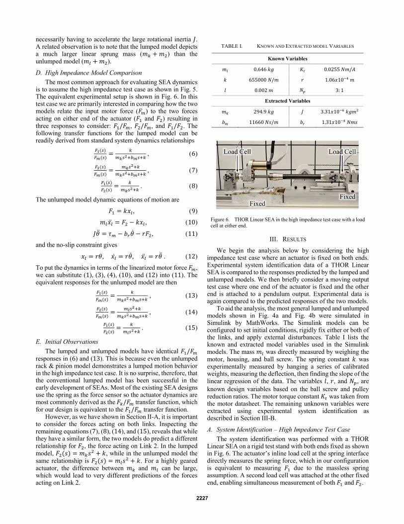
An observation worth noting is that even this unlumped model demonstrates a lumped motion behavior in the high impedance test case which is widely used as a simplified test case to derive the dynamics of SEAs. In the high impedance test case, both sides of the actuator are fixed to ground as shown in Fig. 5 where �̇�1 = �̇�2 = 0. The no-slip condition of the rack & pinion model ensures that for a given pinion rotation (motor/transmission rotation) there is a known pinion translation (motor/transmission translation) which is a function of the gearing ratio. In other words, the translational and rotational inertias of the actuator move in a lumped manner for the high impedance test case.
However, this lumped motion does not hold true for the moving output test case, (i.e. if we allow one or both of the output links to move). Consider the unlumped model in Fig. 4b for an actuator in force control mode with low gains (i.e. slow response). If 𝑚1 is fixed and an impulse load is applied to 𝑚2, the translational mass 𝑚𝑙 of the pinion can accelerate immediately along with 𝑚2 via the spring deflection, without
Figure 4. Lumped and unlumped models for linear ball screw driven
SEAs showing the moving output test case.
Figure 5. Lumped and unlumped models for linear ball screw driven
SEAs showing the high impedance test case.
2226
necessarily having to accelerate the large rotational inertia 𝐽. A related observation is to note that the lumped model depicts a much larger linear sprung mass (𝑚𝑘 + 𝑚2) than the unlumped model (𝑚𝑙 + 𝑚2).
D. High Impedance Model Comparison
The most common approach for evaluating SEA dynamics is to assume the high impedance test case as shown in Fig. 5. The equivalent experimental setup is shown in Fig. 6. In this test case we are primarily interested in comparing how the two models relate the input motor force (𝐹𝑚) to the two forces acting on either end of the actuator (𝐹1 and 𝐹2) resulting in three responses to consider: 𝐹1/𝐹𝑚, 𝐹2/𝐹𝑚, and 𝐹1/𝐹2. The following transfer functions for the lumped model can be readily derived from standard system dynamics relationships
6 𝐹1(𝑠)
𝐹𝑚(𝑠)=
𝑘
𝑚𝑘𝑠2+𝑏𝑚𝑠+𝑘 , 6
7 𝐹2(𝑠)
𝐹𝑚(𝑠)=
𝑚𝑘𝑠2+𝑘
𝑚𝑘𝑠2+𝑏𝑚𝑠+𝑘 , 7
8 𝐹1(𝑠)
𝐹2(𝑠)=
𝑘
𝑚𝑘𝑠2+𝑘 . 8
The unlumped model dynamic equations of motion are
9 𝐹1 = 𝑘𝑥𝑙, 9
10 𝑚𝑙𝑥�̈� = 𝐹2 − 𝑘𝑥𝑙 , 10
11 𝐽�̈� = 𝜏𝑚 − 𝑏𝑟�̇� − 𝑟𝐹2, 11
and the no-slip constraint gives
12 𝑥𝑙 = 𝑟𝜃, 𝑥�̇� = 𝑟�̇�, 𝑥�̈� = 𝑟�̈� . 12
To put the dynamics in terms of the linearized motor force 𝐹𝑚, we can substitute (1), (3), (4), (10), and (12) into (11). The equivalent responses for the unlumped model are then
13 𝐹1(𝑠)
𝐹𝑚(𝑠)=
𝑘
𝑚𝑘𝑠2+𝑏𝑚𝑠+𝑘 , 13
14 𝐹2(𝑠)
𝐹𝑚(𝑠)=
𝑚𝑙𝑠2+𝑘
𝑚𝑘𝑠2+𝑏𝑚𝑠+𝑘 , 14
15 𝐹1(𝑠)
𝐹2(𝑠)=
𝑘
𝑚𝑙𝑠2+𝑘 . 15
E. Initial Observations
The lumped and unlumped models have identical 𝐹1/𝐹𝑚 responses in (6) and (13). This is because even the unlumped rack & pinion model demonstrates a lumped motion behavior in the high impedance test case. It is no surprise, therefore, that the conventional lumped model has been successful in the early development of SEAs. Most of the existing SEA designs use the spring as the force sensor so the actuator dynamics are most commonly derived as the 𝐹𝑘/𝐹𝑚 transfer function, which for our design is equivalent to the 𝐹1/𝐹𝑚 transfer function.
However, as we have shown in Section II-A, it is important to consider the forces acting on both links. Inspecting the remaining equations (7), (8), (14), and (15), reveals that while they have a similar form, the two models do predict a different relationship for 𝐹2, the force acting on Link 2. In the lumped model, 𝐹2(𝑠) = 𝑚𝑘𝑠2 + 𝑘, while in the unlumped model the same relationship is 𝐹2(𝑠) = 𝑚𝑙𝑠
2 + 𝑘. For a highly geared actuator, the difference between 𝑚𝑘 and 𝑚𝑙 can be large, which would lead to very different predictions of the forces acting on Link 2.
III. RESULTS
We begin the analysis below by considering the high impedance test case where an actuator is fixed on both ends. Experimental system identification data of a THOR Linear SEA is compared to the responses predicted by the lumped and unlumped models. We then briefly consider a moving output test case where one end of the actuator is fixed and the other end is attached to a pendulum output. Experimental data is again compared to the predicted responses of the two models.
To aid the analysis, the most general lumped and unlumped models shown in Fig. 4a and Fig. 4b were simulated in Simulink by MathWorks. The Simulink models can be configured to set initial conditions, rigidly fix either or both of the links, and apply external disturbances. Table I lists the known and extracted model variables used in the Simulink models. The mass 𝑚𝑙 was directly measured by weighing the motor, housing, and ball screw. The spring constant 𝑘 was experimentally measured by hanging a series of calibrated weights, measuring the deflection, then finding the slope of the linear regression of the data. The variables 𝑙, 𝑟, and 𝑁𝑝, are
known design variables based on the ball screw and pulley reduction ratios. The motor torque constant 𝐾𝜏 was taken from the motor datasheet. The remaining unknown variables were extracted using experimental system identification as described in Section III-B.
A. System Identification – High Impedance Test Case
The system identification was performed with a THOR Linear SEA on a rigid test stand with both ends fixed as shown in Fig. 6. The actuator’s inline load cell at the spring interface directly measures the spring force, which in our configuration is equivalent to measuring 𝐹1 due to the massless spring assumption. A second load cell was attached at the other fixed end, enabling simultaneous measurement of both 𝐹1 and 𝐹2.
TABLE I. KNOWN AND EXTRACTED MODEL VARIABLES
Known Variables
𝑚𝑙 0.646 𝑘𝑔 𝐾𝜏 0.0255 𝑁𝑚/𝐴
𝑘 655000 𝑁/𝑚 𝑟 1.06𝑥10−4 𝑚
𝑙 0.002 𝑚 𝑁𝑝 3: 1
Extracted Variables
𝑚𝑘 294.9 𝑘𝑔 𝐽 3.31𝑥10−6 𝑘𝑔𝑚2
𝑏𝑚 11660 𝑁𝑠/𝑚 𝑏𝑟 1.31𝑥10−4 𝑁𝑚𝑠
Figure 6. THOR Linear SEA in the high impedance test case with a load
cell at either end.
2227
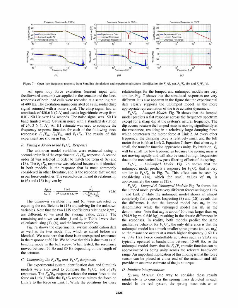
An open loop force excitation (current input with feedforward constant) was applied to the actuator and the force responses of both load cells were recorded at a sampling rate of 400 Hz. The excitation signal consisted of a sinusoidal chirp signal summed with a noise signal. The chirp signal had an amplitude of 480.6 N (2 A) and used a logarithmic sweep from 0.01-150 Hz over 164 seconds. The noise signal was 150 Hz band limited white Gaussian noise with a standard deviation of 240.3 N (1 A). An H1 estimate was used to compute the frequency response function for each of the following three responses: 𝐹1/𝐹𝑚, 𝐹2/𝐹𝑚, and 𝐹1/𝐹2. The results of this experiment are shown in Fig. 7.
B. Fitting a Model to the 𝐹1/𝐹𝑚 Response
The unknown model variables were extracted using a second order fit of the experimental 𝐹1/𝐹𝑚 response. A second order fit was selected in order to match the form of (6) and (13). The 𝐹1/𝐹𝑚 response was selected because it is identical in both models, is the response that is most commonly considered in other literature, and is the response that we use in our force controller. The second order fit and its relationship to (6) and (13) is given by
16 𝐹1(𝑠)
𝐹𝑚(𝑠)=
2166
𝑠2+39.53𝑠+2279=
𝑘
𝑚𝑘
𝑠2+𝑏𝑚𝑚𝑘
𝑠+𝑘
𝑚𝑘
. 16
The unknown variables 𝑚𝑘 and 𝑏𝑚 were extracted by equating the coefficients in (16) and solving for the unknown variables. Note that the two LHS coefficients relating to 𝑘/𝑚𝑘 are different, so we used the average value, 2222.5. The remaining unknown variables 𝐽 and 𝑏𝑟 in Table I were then calculated using (1), (4), and the known variables.
Fig. 7a shows the experimental system identification data as well as the two model fits, which as stated before are identical. We note here that there is an unexpected resonance in the response at 80 Hz. We believe that this is due to an axial bending mode in the ball screw. When tested, the resonance moved between 70 Hz and 80 Hz depending on the length of the actuator.
C. Comparing the 𝐹2/𝐹𝑚 and 𝐹1/𝐹2 Responses
The experimental system identification data and Simulink models were also used to compare the 𝐹2/𝐹𝑚 and 𝐹1/𝐹2 responses. The 𝐹2/𝐹𝑚 response relates the motor force to the force on Link 2 while the 𝐹1/𝐹2 response relates the force on Link 2 to the force on Link 1. While the equations for these
relationships for the lumped and unlumped models are very similar, Fig. 7 shows that the simulated responses are very different. It is also apparent in the figure that the experimental data clearly supports the unlumped model as the more appropriate representation of the true actuator dynamics.
𝐹2/𝐹𝑚 – Lumped Model: Fig. 7b shows that the lumped model predicts a flat response across the frequency spectrum except for a sharp dip at the system’s natural frequency. The dip occurs because the lumped mass is moving significantly at the resonance, resulting in a relatively large damping force which counteracts the motor force at Link 2. At every other frequency, the damping force is relatively small and the full motor force is felt at Link 2. Equation 7 shows that when 𝑥�̇� is small, the transfer function approaches unity. By intuition, 𝑥�̇� will be small for low frequencies because the sprung mass is not moving rapidly and will also be small at high frequencies due to the mechanical low pass filtering effects of the spring.
𝐹2/𝐹𝑚 – Unlumped Model: Fig. 7b shows that the unlumped model predicts a response for 𝐹2/𝐹𝑚 that is very similar to 𝐹1/𝐹𝑚 in Fig. 7a. This effect can be seen by considering (14), which for small values of 𝑚𝑙 is approximately the same as (13).
𝐹1/𝐹2 – Lumped & Unlumped Models: Fig. 7c shows that the lumped model predicts very different forces acting on Link 1 and Link 2 while the unlumped model shows an almost completely flat response. Inspecting (8) and (15) reveals that the difference is that the lumped model has 𝑚𝑘 in the denominator while the unlumped model has 𝑚𝑙 in the denominator. Note that 𝑚𝑘 is about 450 times larger than 𝑚𝑙 (294.9 kg vs. 0.646 kg), resulting in the drastic differences in the responses. In reality, both models predict the same qualitative behavior for 𝐹1/𝐹2; the only difference is that the unlumped model has a much smaller sprung mass (𝑚𝑙 vs. 𝑚𝑘) so the resonance occurs at a much higher frequency (160 Hz vs. 7.47 Hz). Force controllable actuators such as SEAs are typically operated at bandwidths between 15-60 Hz, so the unlumped model shows that the 𝐹1/𝐹2 transfer function can be approximated as being unity across the relevant bandwidth range. An important implication of this finding is that the force sensor can be placed at either end of the actuator and still provide an accurate estimate of the joint torque.
D. Intuitive interpretations
Sprung Masses: One way to consider these results intuitively is to consider the sprung mass depicted in each model. In the real system, the sprung mass acts as an
Figure 7. Open loop frequency response from Simulink simulations and experimental system identification for 𝐹1/𝐹𝑚 (a), 𝐹2/𝐹𝑚 (b), and 𝐹1/𝐹2 (c).
2228
intermediate inertia, the dynamics of which influence the forces acting on the two links to which it is attached. The lumped model shows a very large lumped sprung mass which, if accelerating, will result in different forces at the two links. The unlumped model, on the other hand, shows a relatively small sprung mass, keeping the two forces almost equal.
Load Path: The lumped model shows that any forces propagating from Link 1 to Link 2 would have to act through the motor damping or motor force. The rack and pinion model, however, shows an almost direct feedthrough of forces from Link 1 to Link 2. The only difference in forces would be associated with the acceleration of the small translational mass 𝑚𝑙. This can be demonstrated mechanically by considering that there is a direct load path for forces to propagate axially through the ball screw without having to first accelerate the motor and transmission inertias.
Reaction Forces: Another way to consider the results in Fig. 7 intuitively is by looking at the predicted reaction forces acting on Link 2. In the lumped model, the full motor reaction force 𝐹𝑚 acts on Link 2. In the unlumped model, the motor reaction force does not act on Link 2 directly. Instead, it acts out of plane between the pinion gear and a virtual ground. The mechanical equivalent of this effect has to do with how the reaction torque is handled. In a ball screw driven linear actuator, the reaction torque of the motor is counteracted by the anti-rotation mechanism that prevents the ball nut from spinning freely. Various designs implement the anti-rotation mechanism via guiderails, keyways, or in the case of the THOR Linear SEA, with u-joints at either end. Irregardless of the mechanism, the motor reaction torque is either transmitted into torsion in the structure of the actuator or torsion in the structure of the robot.
E. Moving Output Results
To see if the models extend beyond the high impedance test case, we investigated a moving output test case with both experimental and simulation results.
As discussed in Section II-E, both the lumped and unlumped models predict the same 𝐹1/𝐹𝑚 response for the high impedance test case because the pinion’s translational and rotational inertias move in a lumped manner due to the no-slip condition. However, this relationship breaks down if either or both of the links are allowed to move. The pinion’s translation and rotation are still coupled through the no-slip condition of the ball screw; however, there can now be translation without rotation and vice versa, depending on the loading conditions.
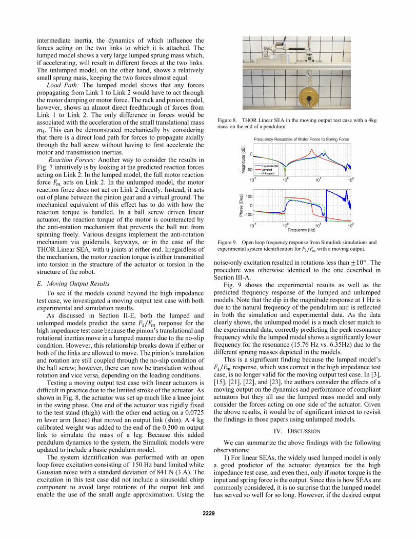
Testing a moving output test case with linear actuators is difficult in practice due to the limited stroke of the actuator. As shown in Fig. 8, the actuator was set up much like a knee joint in the swing phase. One end of the actuator was rigidly fixed to the test stand (thigh) with the other end acting on a 0.0725 m lever arm (knee) that moved an output link (shin). A 4 kg calibrated weight was added to the end of the 0.300 m output link to simulate the mass of a leg. Because this added pendulum dynamics to the system, the Simulink models were updated to include a basic pendulum model.
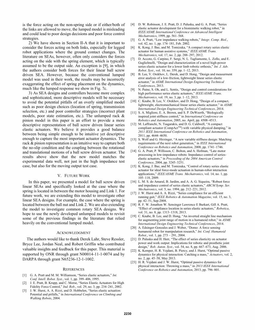
The system identification was performed with an open loop force excitation consisting of 150 Hz band limited white Gaussian noise with a standard deviation of 841 N (3 A). The excitation in this test case did not include a sinusoidal chirp component to avoid large rotations of the output link and enable the use of the small angle approximation. Using the
noise-only excitation resulted in rotations less than ±10° . The procedure was otherwise identical to the one described in Section III-A.
Fig. 9 shows the experimental results as well as the predicted frequency response of the lumped and unlumped models. Note that the dip in the magnitude response at 1 Hz is due to the natural frequency of the pendulum and is reflected in both the simulation and experimental data. As the data clearly shows, the unlumped model is a much closer match to the experimental data, correctly predicting the peak resonance frequency while the lumped model shows a significantly lower frequency for the resonance (15.76 Hz vs. 6.35Hz) due to the different sprung masses depicted in the models.
This is a significant finding because the lumped model’s 𝐹1/𝐹𝑚 response, which was correct in the high impedance test case, is no longer valid for the moving output test case. In [3], [15], [21], [22], and [23], the authors consider the effects of a moving output on the dynamics and performance of compliant actuators but they all use the lumped mass model and only consider the forces acting on one side of the actuator. Given the above results, it would be of significant interest to revisit the findings in those papers using unlumped models.
IV. DISCUSSION
We can summarize the above findings with the following observations:
1) For linear SEAs, the widely used lumped model is only a good predictor of the actuator dynamics for the high impedance test case, and even then, only if motor torque is the input and spring force is the output. Since this is how SEAs are commonly considered, it is no surprise that the lumped model has served so well for so long. However, if the desired output
Figure 8. THOR Linear SEA in the moving output test case with a 4kg
mass on the end of a pendulum.
Figure 9. Open loop frequency response from Simulink simulations and
experimental system identification for 𝐹1/𝐹𝑚 with a moving output.
2229
is the force acting on the non-spring side or if either/both of the links are allowed to move, the lumped model is misleading and could lead to poor design decisions and poor force control strategies.
2) We have shown in Section II-A that it is important to consider the forces acting on both links, especially for legged robot applications where the ground contact changes. The literature on SEAs, however, often only considers the forces acting on the side with the spring element, which is typically assumed to be the output side. An exception is [9], in which the authors consider both forces for their linear ball screw driven SEA. However, because the conventional lumped model was used in their work, the results may be incorrectly exaggerating the effect of spring placement on the dynamics, much like the lumped response we show in Fig. 7c.
3) As SEA designs and controllers become more complex and sophisticated, more descriptive models will be necessary to avoid the potential pitfalls of an overly simplified model such as poor design choices (location of spring, transmission selection, etc.) and poor controller strategies (incorrect plant models, poor state estimation, etc.). The unlumped rack & pinion model in this paper is an effort to provide a more descriptive representation of ball screw driven linear series elastic actuators. We believe it provides a good balance between being simple enough to be intuitive yet descriptive enough to capture the most important actuator dynamics. The rack & pinion representation is an intuitive way to capture both the no-slip condition and the coupling between the rotational and translational motions of a ball screw driven actuator. The results above show that the new model matches the experimental data well, not just in the high impedance test case, but also for the moving output test case.
V. FUTURE WORK
In this paper, we presented a model for ball screw driven linear SEAs and specifically looked at the case where the spring is located in between the motor housing and Link 1. For future work, we are extending this model to investigate other linear SEA designs. For example, the case where the spring is located between the ball nut and Link 2. We are also extending the model to investigate common rotary SEA designs. We hope to use the newly developed unlumped models to revisit some of the previous findings in the literature that relied heavily on the conventional lumped model.
ACKNOWLEDGMENT
The authors would like to thank Derek Lahr, Steve Ressler,
Bryce Lee, Jordan Neal, and Robert Griffin who contributed
valuable insights and feedback for this paper. This material is
supported by ONR through grant N00014-11-1-0074 and by
DARPA through grant N65236-12-1-1002.
REFERENCES
[1] G. A. Pratt and M. M. Williamson, “Series elastic actuators,” Int.
Conf. Intell. Robot. Syst., vol. 1, pp. 399–406, 1995. [2] J. E. Pratt, B. Krupp, and C. Morse, “Series Elastic Actuators for High
Fidelity Force Control,” Ind. Rob., vol. 29, no. 3, pp. 234–241, 2002.
[3] J. W. Hurst, A. A. Rizzi, and D. Hobbelen, “Series elastic actuation: Potential and pitfalls,” in International Conference on Climbing and
Walking Robots, 2004.
[4] D. W. Robinson, J. E. Pratt, D. J. Paluska, and G. A. Pratt, “Series
elastic actuator development for a biomimetic walking robot,” in
IEEE/ASME International Conference on Advanced Intelligent
Mechatronics, 1999, pp. 561–568.
[5] G. A. Pratt, “Low impedance walking robots,” Integr. Comp. Biol., vol. 42, no. 1, pp. 174–181, Feb. 2002.
[6] K. Kong, J. Bae, and M. Tomizuka, “A compact rotary series elastic
actuator for human assistive systems,” IEEE/ASME Trans. Mechatronics, vol. 17, no. 2, pp. 288–297, 2012.
[7] D. Accoto, G. Carpino, F. Sergi, N. L. Tagliamonte, L. Zollo, and E.
Guglielmelli, “Design and characterization of a novel high-power series elastic actuator for a lower limb robotic orthosis,” Int. J. Adv.
Robot. Syst., vol. 10, no. 359, pp. 1–12, 2013.
[8] B. Lee, V. Orekhov, L. Derek, and D. Hong, “Design and measurment error analysis of a low-friction, lightweight linear series elastic
actuator,” in ASME International Design Engineering Technical
Conferences, 2013. [9] N. Paine, S. Oh, and L. Sentis, “Design and control considerations for
high performance series elastic actuators,” IEEE/ASME Trans.
Mechatronics, vol. 19, no. 3, pp. 1–12, 2013. [10] C. Knabe, B. Lee, V. Orekhov, and D. Hong, “Design of a compact,
lightweight, electromechanical linear series elastic actuator,” in ASME
International Design Engineering Technical Conferences, 2014. [11] S. A. Migliore, E. A. Brown, and S. P. DeWeerth, “Biologically
inspired joint stiffness control,” in International Conference on
Robotics and Automation, 2005, no. April, pp. 4508–4513. [12] M. Laffranchi, N. Tsagarakis, and D. G. Caldwell, “A compact
compliant actuator (CompActTM) with variable physical damping,” in 2011 IEEE International Conference on Robotics and Automation,
2011, pp. 4644–4650.
[13] S. Wolf and G. Hirzinger, “A new variable stiffness design: Matching requirements of the next robot generation,” in IEEE International
Conference on Robotics and Automation, 2008, pp. 1741–1746.
[14] G. A. Pratt, P. Willisson, C. Bolton, and A. Hofman, “Late motor processing in low-impedance robots: Impedance control of series-
elastic actuators,” in Proceeding of the 2004 American Control
Conference, 2004, pp. 3245–3251. [15] K. Kong, J. Bae, and M. Tomizuka, “Control of rotary series elastic
actuator for ideal force-mode actuation in human-robot interaction
applications,” IEEE/ASME Trans. Mechatronics, vol. 14, no. 1, pp. 105–118, 2009.
[16] L. M. S. do Amaral, B. Jardim, and A. A. G. Siqueira, “Robust force
and impedance control of series elastic actuators,” ABCM Symp. Ser. Mechatronics, vol. 5, no. 1994, pp. 212–221, 2012.
[17] J. W. Hurst and A. A. Rizzi, “Series compliance for an efficient
running gait,” IEEE Robotics & Automation Magazine, vol. 15, no. 3, pp. 42–51, Sep-2008.
[18] R. F. W. Jonathon W. Sensinger Lawrence E Burkart, Gill A. Pratt,
“Effect of compliance location in series elastic actuators,” Robotica, vol. 31, no. 8, pp. 1313–1318, 2013.
[19] C. Knabe, B. Lee, and D. Hong, “An inverted straight line mechanism
for augmenting joint range of motion in a humanoid robot,” in ASME International Design Engineering Technical Conferences, 2014.
[20] A. Edsinger-Gonzales and J. Weber, “Domo: A force sensing
humanoid robot for manipulation research,” Int. Conf. Humanoid Robot., vol. 1, pp. 273 – 291, 2004.
[21] D. Paluska and H. Herr, “The effect of series elasticity on actuator
power and work output: Implications for robotic and prosthetic joint design,” Rob. Auton. Syst., vol. 54, no. 8, pp. 667–673, Aug. 2006.
[22] K. Kemper, H. R. Vejdani, B. Piercy, and J. Hurst, “Optimal passive
dynamics for physical interaction: Catching a mass,” Actuators, vol. 2, no. 2, pp. 45–58, May 2013.
[23] H. R. Vejdani and J. W. Hurst, “Optimal passive dynamics for
physical interaction: Throwing a mass,” in 2013 IEEE International Conference on Robotics and Automation, 2013, pp. 796–801.
2230