Embed Size (px)
Citation preview

Self-Deployed Extremely Large Low Mass Space Structures
Devon G. Crowe, Prakash Joshi, Ed Rietman, and Kophu Chang*
Physical Sciences, Inc.
March 7, 2007
*With a little help from our friends W. Cash and A. Labeyrie
Low Mass Approach• Rigid structures can be fabricated from bubbles
or foams that are inflated at very low pressures (~ 10-4 atmospheres) before being made rigid by solar UV curing

Features • Bubbles and foam with individual cell sizes up to 100
meters• Structural spans could exceed 10,000 kilometers in
micro-g environments• Structural densities as low as 15 µg/cc• Areal densities under 1g/m2
• Foam densities that tessellate volume in a structured way to maximize density in regions of stress
• Phononic crystals designed into the foam tailor the stiffness of structural members
• In-situ bubble and foam formation and rigidization allows a deployed structure volume of up to 108 times the spacecraft volume that deploys it
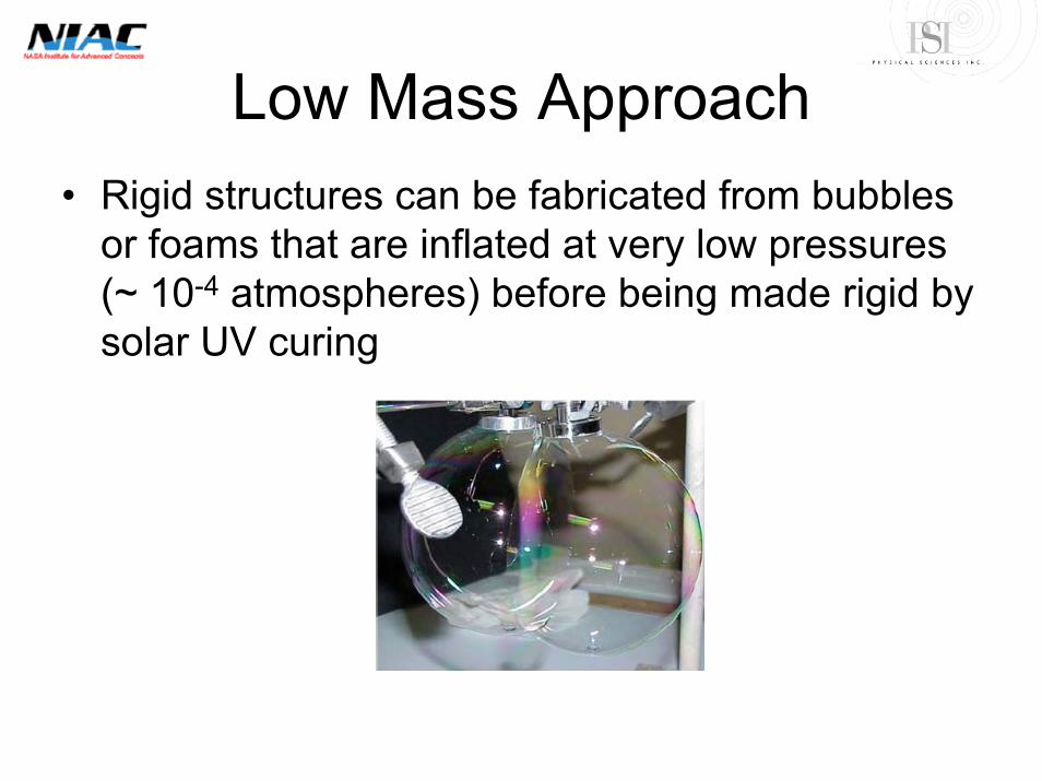
Applications• Self-sustaining space habitats for extended duration uses
– Space stations – Planetary expeditions– Interstellar voyages– Planetary surface buildings
• Astronomical telescope structures that replace formation flying requirements at very large scales
– Interferometer arrays– Pinhole imagers– Long focal length Fresnel plate telescopes
• Large area photon sails, stellar energy collectors, or astronomical primary photon collection surfaces
– Interstellar photon sailing– Solar powered propulsion– Laser propulsion at extreme ranges– Beamed power transmission– Photon perturbation of comet orbits for planetary protection– Astronomical research on the origins of the universe and on evidence of life on planets within
other solar systems– Solar earth shade for global warming mitigation– Optical apertures with tailored radius of curvature up to 100 meters in diameter– Solar ablation of cometary surfaces to deflect NEO objects from earth-intersecting orbits for
planetary defense
Deployed Structures• Example Structures
– Orbiting large spheres with multi-kilometer dimensions– Domes, or either cylindrical or rectangular prisms, for use as
buildings on planetary surfaces– Long structural elements to hundreds of kilometers in size and
beyond– Large area thin walls to tens of thousands of square kilometers
and beyond• Deployment Methods
– Bubble inflation followed by rigidization– Frame member inflation followed by rigidization– Frame member inflation followed by suspending “soap film”
analogs followed by rigidization
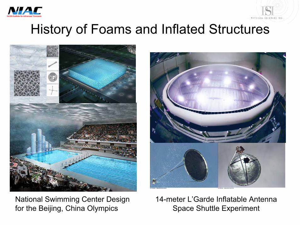
History of Foams and Inflated Structures
National Swimming Center Design for the Beijing, China Olympics
14-meter L’Garde Inflatable Antenna Space Shuttle Experiment

Foam Structural Members• The strength of a cellular structure (foam) is due to a
combination of the aggregated rigidity of the cell boundaries and the net tensile strength of the cell walls.
• The aggregate rigidity is a function of geometry, density, and materials
• Foam structural members support or align the films that will be detailed in this presentation
Penrose volume
tessellation
Single and Dual Hyperbolic Tesselations
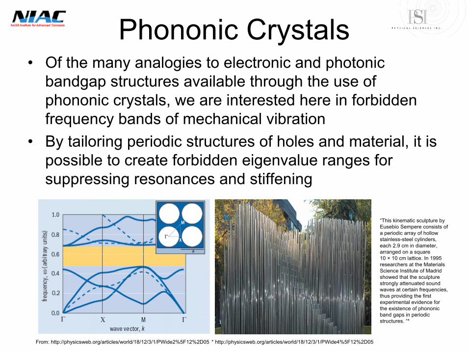
Phononic Crystals• Of the many analogies to electronic and photonic
bandgap structures available through the use of phononic crystals, we are interested here in forbidden frequency bands of mechanical vibration
• By tailoring periodic structures of holes and material, it is possible to create forbidden eigenvalue ranges for suppressing resonances and stiffening
From: http://physicsweb.org/articles/world/18/12/3/1/PWide2%5F12%2D05 * http://physicsweb.org/articles/world/18/12/3/1/PWide4%5F12%2D05
“This kinematic sculpture by Eusebio Sempere consists of a periodic array of hollow stainless-steel cylinders, each 2.9 cm in diameter, arranged on a square 10 × 10 cm lattice. In 1995 researchers at the Materials Science Institute of Madrid showed that the sculpture strongly attenuated sound waves at certain frequencies, thus providing the first experimental evidence for the existence of phononicband gaps in periodic structures. “*
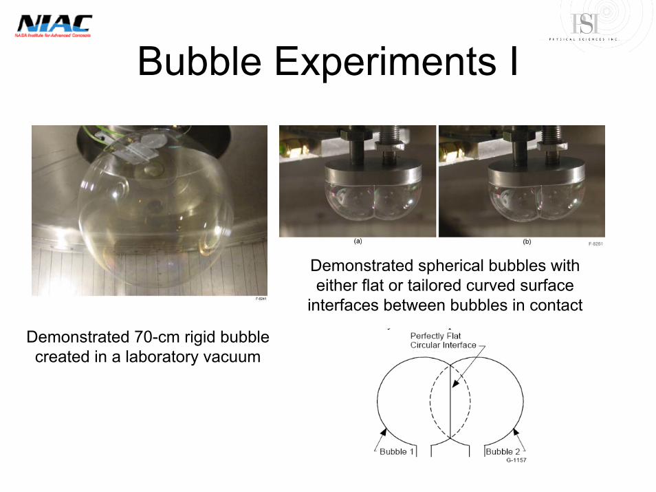
Bubble Experiments I
Demonstrated spherical bubbles with either flat or tailored curved surface
interfaces between bubbles in contact
Demonstrated 70-cm rigid bubble created in a laboratory vacuum
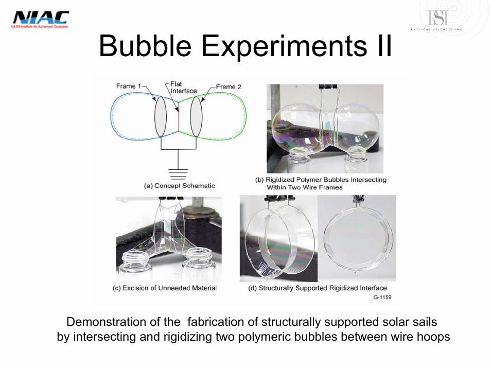
Bubble Experiments II
Demonstration of the fabrication of structurally supported solar sailsby intersecting and rigidizing two polymeric bubbles between wire hoops
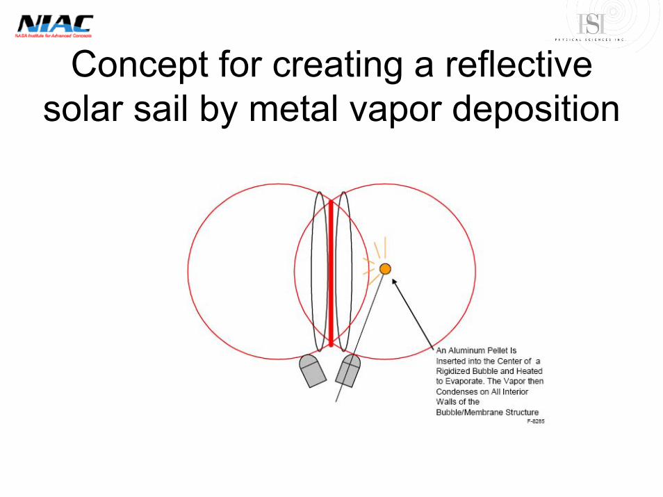
Concept for creating a reflective solar sail by metal vapor deposition
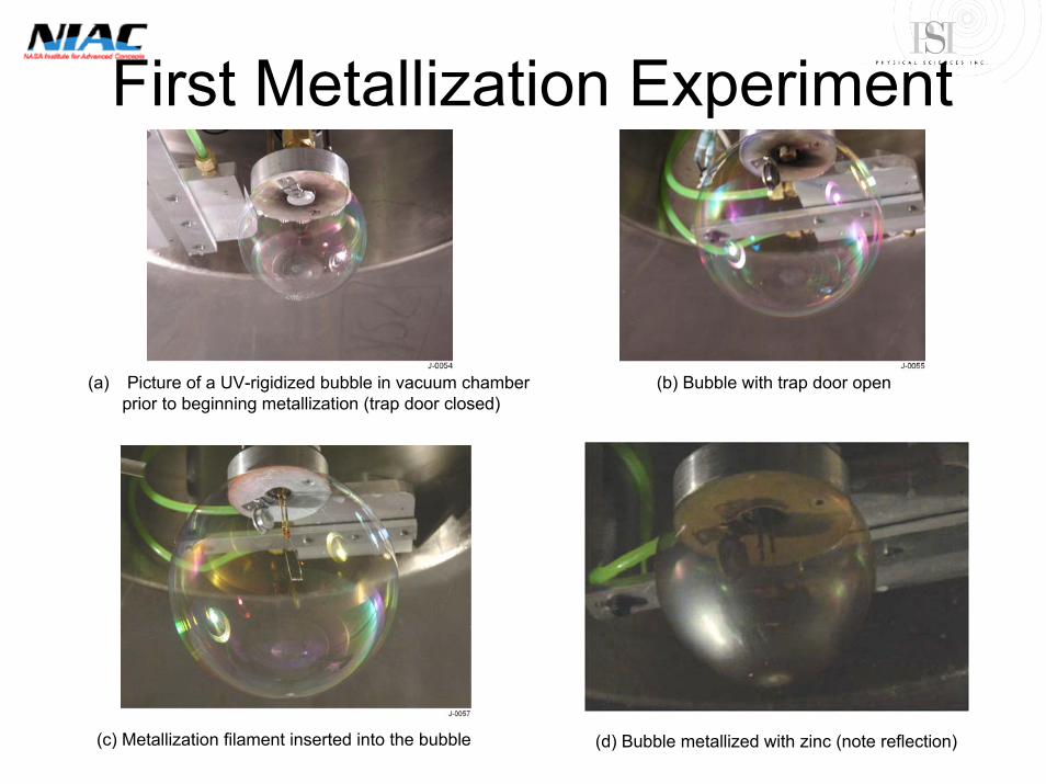
First Metallization Experiment
(a) Picture of a UV-rigidized bubble in vacuum chamber prior to beginning metallization (trap door closed)
(b) Bubble with trap door open
(c) Metallization filament inserted into the bubble (d) Bubble metallized with zinc (note reflection)
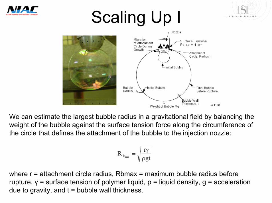
Scaling Up I
We can estimate the largest bubble radius in a gravitational field by balancing the weight of the bubble against the surface tension force along the circumference of the circle that defines the attachment of the bubble to the injection nozzle:
where r = attachment circle radius, Rbmax = maximum bubble radius before rupture, γ = surface tension of polymer liquid, ρ = liquid density, g = acceleration due to gravity, and t = bubble wall thickness.
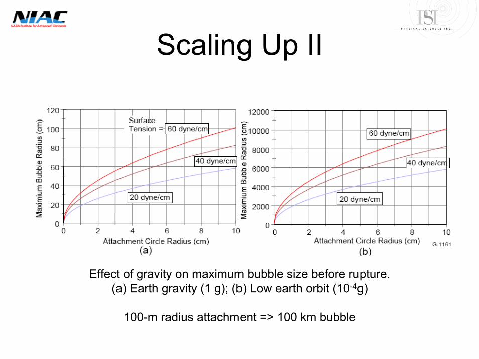
Scaling Up II
Effect of gravity on maximum bubble size before rupture. (a) Earth gravity (1 g); (b) Low earth orbit (10-4g)
100-m radius attachment => 100 km bubble
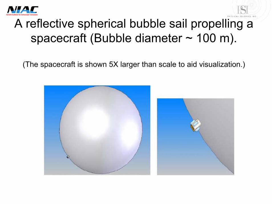
A reflective spherical bubble sail propelling a spacecraft (Bubble diameter ~ 100 m).
(The spacecraft is shown 5X larger than scale to aid visualization.)
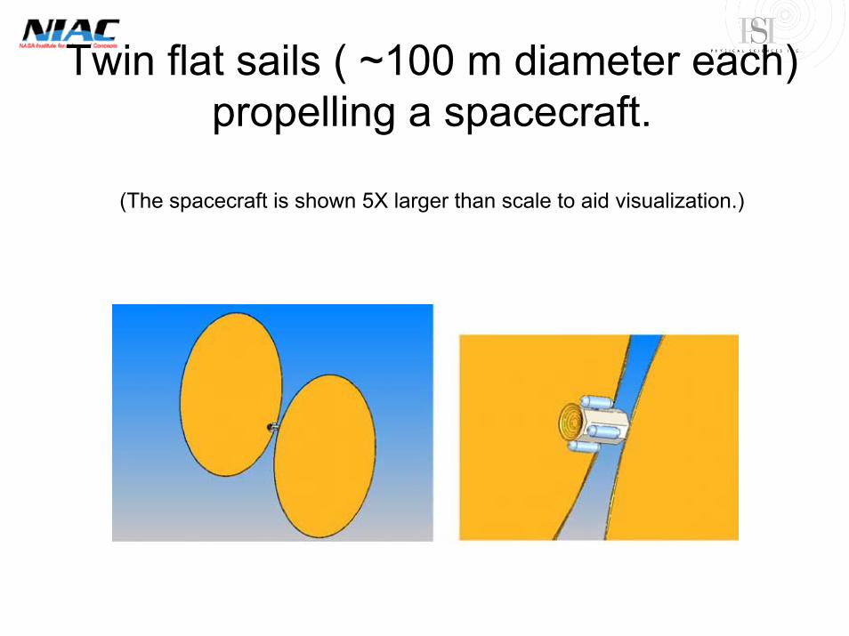
Twin flat sails ( ~100 m diameter each) propelling a spacecraft.
(The spacecraft is shown 5X larger than scale to aid visualization.)

Four flat sails ( ~100 m diameter each) propelling a spacecraft.
(The spacecraft is shown 5X larger than scale to aid visualization.)
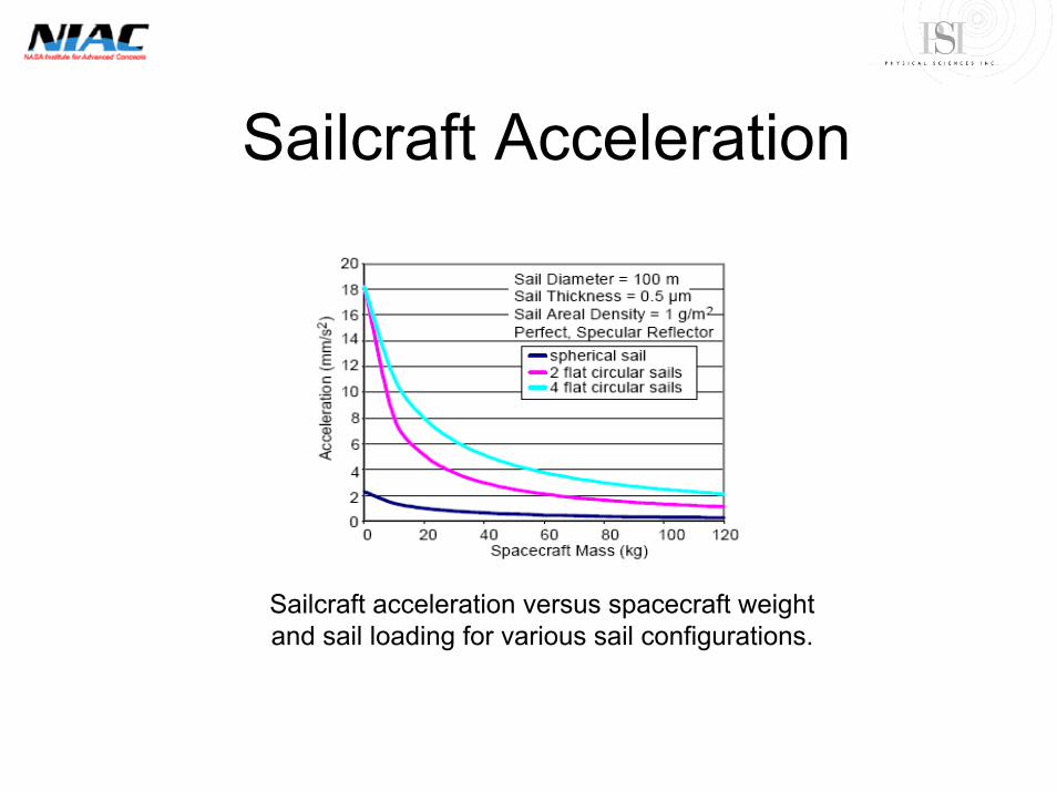
Sailcraft Acceleration
Sailcraft acceleration versus spacecraft weight and sail loading for various sail configurations.

Plans for NIAC Phase 2• Phase 2 is intended to combine Mission Designs
with further laboratory development• Webster Cash has agreed to join the team for
Phase 2 to integrate the concept into both the New Worlds Imager and one additional mission concept to be called Maxim
• Antoine Labeyrie has contributed suggestions for large space telescope applications that include the Hypertelescope
• One Phase 2 goal is to lay the foundation for flight missions for Block 2020
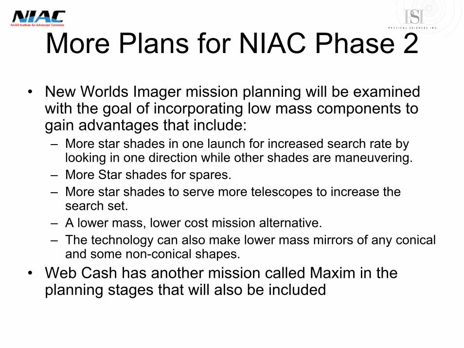
More Plans for NIAC Phase 2• New Worlds Imager mission planning will be examined
with the goal of incorporating low mass components to gain advantages that include:– More star shades in one launch for increased search rate by
looking in one direction while other shades are maneuvering. – More Star shades for spares. – More star shades to serve more telescopes to increase the
search set. – A lower mass, lower cost mission alternative. – The technology can also make lower mass mirrors of any conical
and some non-conical shapes. • Web Cash has another mission called Maxim in the
planning stages that will also be included
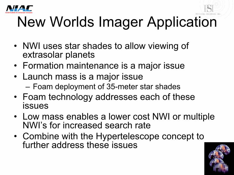
New Worlds Imager Application• NWI uses star shades to allow viewing of
extrasolar planets • Formation maintenance is a major issue• Launch mass is a major issue
– Foam deployment of 35-meter star shades • Foam technology addresses each of these
issues• Low mass enables a lower cost NWI or multiple
NWI’s for increased search rate• Combine with the Hypertelescope concept to
further address these issues
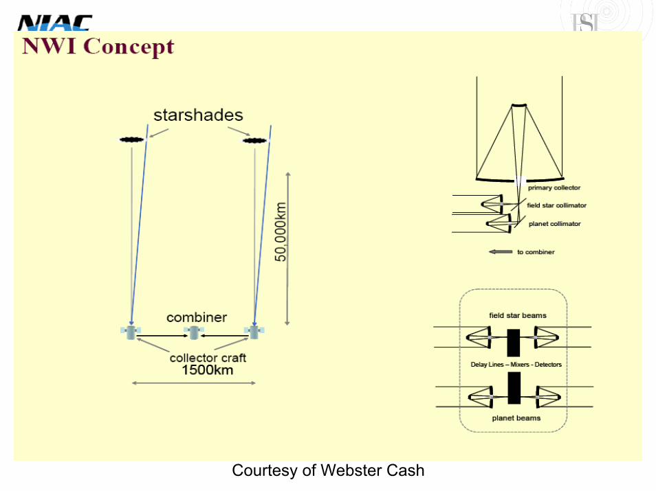
Courtesy of Webster Cash
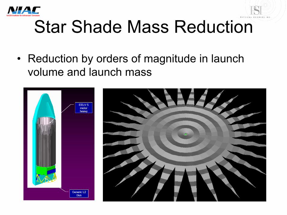
Star Shade Mass Reduction
• Reduction by orders of magnitude in launch volume and launch mass

Hypertelescope Concept• A natural application of the extremely large
low mass spherical bubble fabrication technique is the Hypertelescope
• The Hypertelescope combines the low mass high resolution features of an interferometer with the image quality of a filled aperture
• Antoine Labeyrie has devised cornographicconcepts for the application to direct extra-solar planetary imaging
Figures Courtesy of Antoine Labeyrie
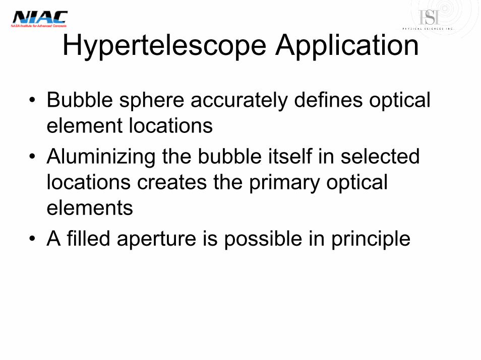
Hypertelescope Application
• Bubble sphere accurately defines optical element locations
• Aluminizing the bubble itself in selected locations creates the primary optical elements
• A filled aperture is possible in principle
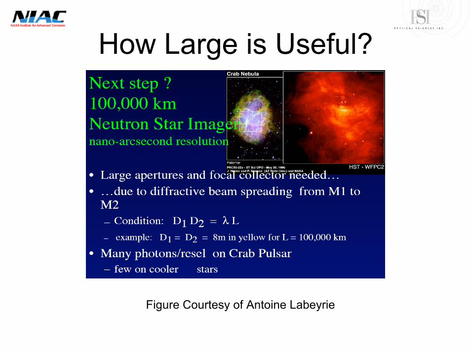
How Large is Useful?
Figure Courtesy of Antoine Labeyrie
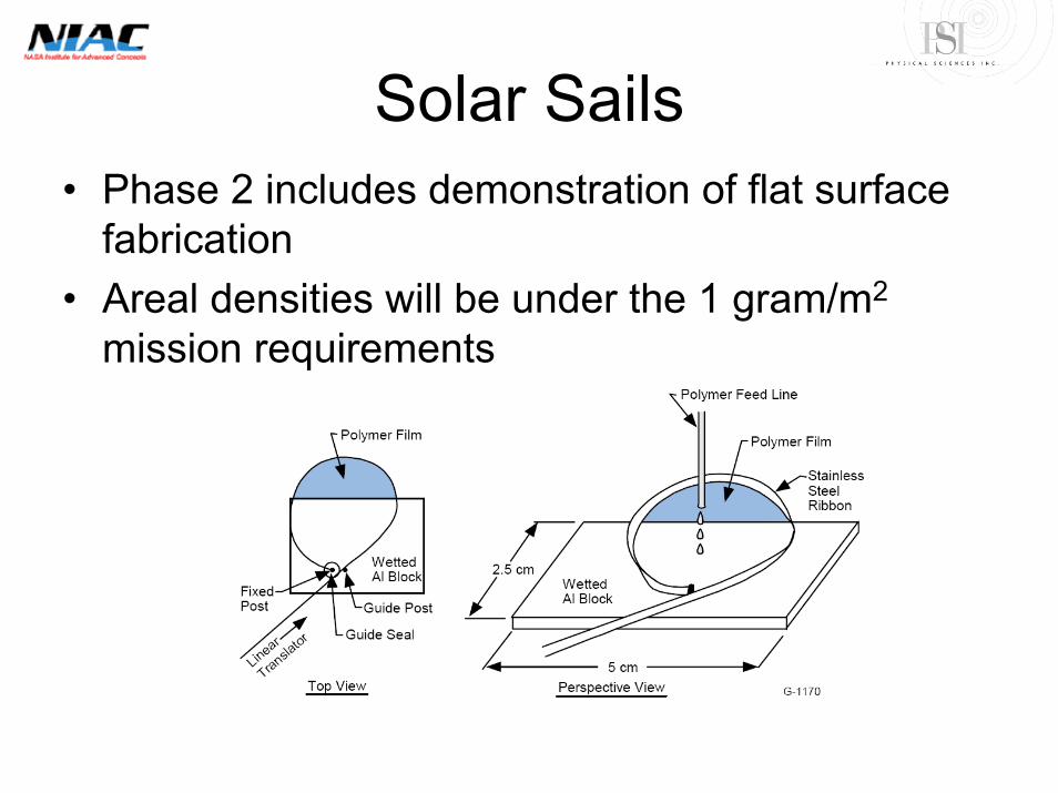
Solar Sails• Phase 2 includes demonstration of flat surface
fabrication• Areal densities will be under the 1 gram/m2
mission requirements

Solar Sail Mission Requirements

Summary• Deployment of Rigid Bubbles has been demonstrated in the laboratory
– Spheres– Flats– Curved surfaces– Theoretically Scalable to 100 km single bubble in low earth orbit– Theoretically Scalable to 1,000 km single bubble in deep space– Foam structural element span can far exceed single bubble in extent
• Suitability for selected missions has been analyzed– Solar sails– Extra solar planet imaging telescopes
• We propose to design missions in Phase 2 that could fly in the 2020 to 2030 mission planning period
– New Worlds Imager (Web Cash)– Maxim (Web Cash)– Hypertelescope embodiments– Solar Sails
• We propose to demonstrate laboratory feasibility of miniature mission prototype structural elements and optical surfaces


![DTLS-HIMMO: Efficiently Securing PQ world with a …[2] O. Garcia Morchon, Ronald Rietman, Igor E. Shparlinski, and Ludo Tolhuizen. Interpolation and approximation of polynomials in](https://img.pdfslide.us/doc/110x75/5fa4c9d570d33637867ac438/dtls-himmo-efficiently-securing-pq-world-with-a-2-o-garcia-morchon-ronald-rietman.jpg)