Embed Size (px)
Citation preview

SELECTIVE LASER MELTING OF BIOCOMPATIBLE METALS FOR RAPID MANUFACTURING OF MEDICAL PARTS
Ben Vandenbroucke, Jean-Pierre Kruth
Division PMA, Department of Mechanical Engineering, Katholieke Universiteit Leuven, Belgium
Abstract
In recent years, digitizing and automation have gained an important place in fabrication of medical parts. Rapid Manufacturing could be very suitable for medical applications due to their complex geometry, low volume and strong individualization. The presented study investigates the possibility to produce medical or dental parts by Selective Laser Melting (SLM). The SLM-process is optimized and fully characterized for two biocompatible metal alloys: TiAl6V4 and CoCrMo. This paper reports on mechanical and chemical properties and discusses geometrical feasibility including accuracy and surface roughness. The potential of SLM as medical manufacturing technique is proved by a developed procedure to fabricate frameworks for complex dental prostheses.
Introduction
Over the last decade Reverse Engineering, Computer-Aided Design, Computer-Aided Manufacturing and Rapid Prototyping (RE, CAD, CAM, RP) have been employed in medicine and dentistry [1]. Diagnostic tools have become increasingly more sophisticated and medical imaging technology can now present patient data with high precision. Virtual planning environments allow data visualization and manipulation. With RP there came a way to produce custom physical models of patient anatomy providing doctors the means for tactile interaction which facilitates preoperative planning of complex surgeries. In addition, RP-generated replicas act often as basis for customization of treatment devices such as craniofacial plates. RP-techniques are also used to create custom treatment aides such as dental drilling guides that transfer the digital planning to the patient in a reliable way. Because of technical improvements of Layer Manufacturing (LM) processes and due to the possibility to process all kind of metals Rapid Prototyping evolved to Rapid Manufacturing (RM) in recent years [2, 3]. Medical and dental applications could take advantage of this evolution by using LM techniques not only for plastic devices like visual anatomical models or one-time surgical guides, but also for functional implants or prostheses with long-term consistency made from a biocompatible metal.
This paper discusses the use of Selective Laser Melting (SLM) as RM technique for medical applications. SLM is a layer-wise material addition technique that allows generating complex 3D parts by selectively melting successive layers of metal powder on top of each other, using the thermal energy supplied by a focused and computer controlled laser beam [4, 5]. Medical and dental applications are very suitable to be produced by SLM due to their complex geometry, strong individualization and high aggregate price. Moreover, the manufacturing of multiple unique parts in a single production run enables mass customization.
Reviewed, accepted September 14, 2006
148
To turn SLM into a manufacturing technique for implants or prostheses, some important conditions have to be fulfilled. The laser melted parts have to meet strict material requirementsregarding mechanical and chemical properties and the process must guarantee high accuracy and appropriate surface roughness. In this study the SLM process is optimized and fully characterized according to these requirements for two biocompatible metal alloys, TiAl6V4 and CoCrMo. Adental prosthesis produced by SLM shows the potential of SLM as a medical manufacturingtechnique.
Materials and methods
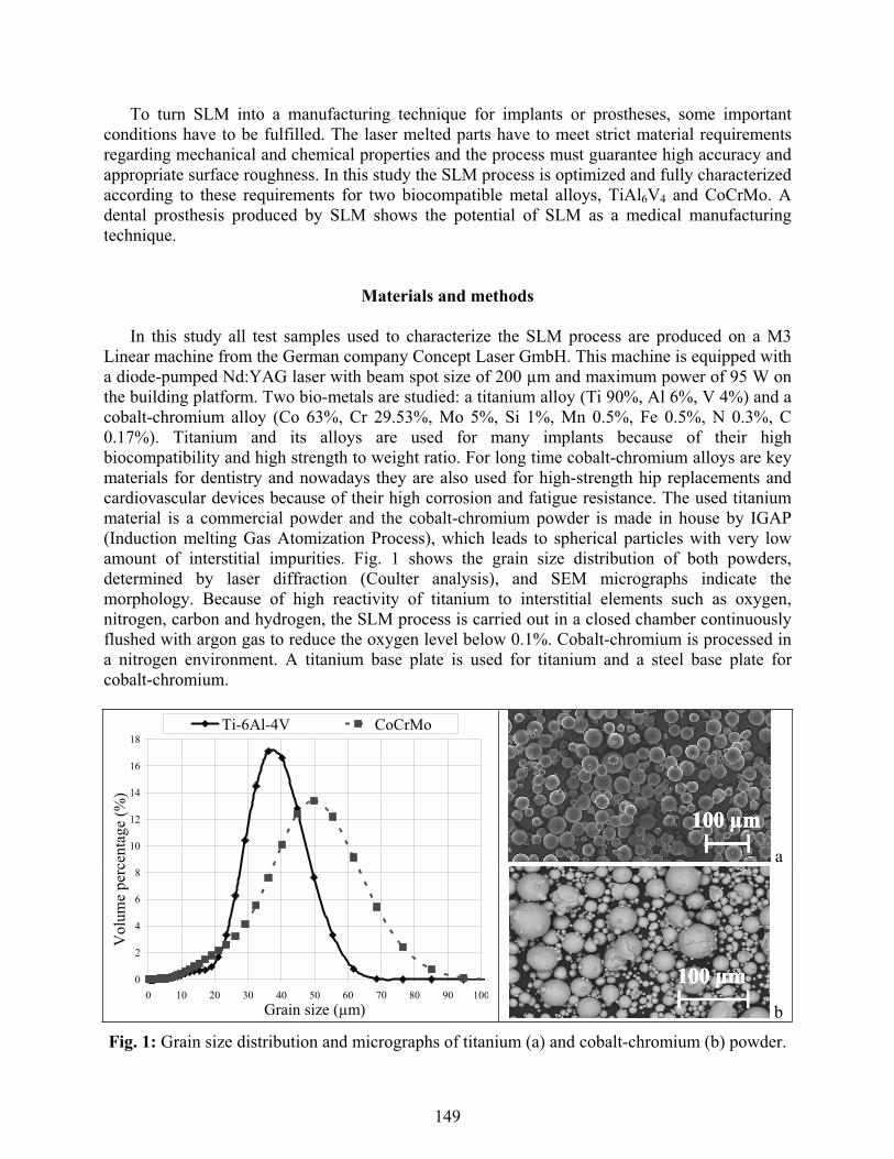
In this study all test samples used to characterize the SLM process are produced on a M3 Linear machine from the German company Concept Laser GmbH. This machine is equipped with a diode-pumped Nd:YAG laser with beam spot size of 200 μm and maximum power of 95 W on the building platform. Two bio-metals are studied: a titanium alloy (Ti 90%, Al 6%, V 4%) and a cobalt-chromium alloy (Co 63%, Cr 29.53%, Mo 5%, Si 1%, Mn 0.5%, Fe 0.5%, N 0.3%, C 0.17%). Titanium and its alloys are used for many implants because of their highbiocompatibility and high strength to weight ratio. For long time cobalt-chromium alloys are key materials for dentistry and nowadays they are also used for high-strength hip replacements and cardiovascular devices because of their high corrosion and fatigue resistance. The used titanium material is a commercial powder and the cobalt-chromium powder is made in house by IGAP (Induction melting Gas Atomization Process), which leads to spherical particles with very lowamount of interstitial impurities. Fig. 1 shows the grain size distribution of both powders, determined by laser diffraction (Coulter analysis), and SEM micrographs indicate the morphology. Because of high reactivity of titanium to interstitial elements such as oxygen,nitrogen, carbon and hydrogen, the SLM process is carried out in a closed chamber continuously flushed with argon gas to reduce the oxygen level below 0.1%. Cobalt-chromium is processed in a nitrogen environment. A titanium base plate is used for titanium and a steel base plate forcobalt-chromium.
a
0
2
4
6
8
10
12
14
16
18
0 10 20 30 40 50 60 70 80 90 100Grain size (μm)
Vol
ume
perc
enta
ge (%
)
Ti-6Al-4V CoCrMo
b
Fig. 1: Grain size distribution and micrographs of titanium (a) and cobalt-chromium (b) powder.
149
SLM is a complex thermo-physical process which depends on a lot of material, laser, scan and environmental parameters. For both selected materials, a parameter study has been performedto optimize the process regarding part density, since porosity has a harmful effect on the mechanical properties of the part. Four main process parameters are selected for experimentation:laser power, layer thickness, scan speed and hatching space. These factors determine the energysupplied by the laser beam to a volumetric unit of powder material, defined as energy density, an experimental quantity which has large influence on part density:
layerhatchingscan
laserdensity tsv
PE
where Edensity = energy density, Plaser = laser power, vscan = scan speed, shatching = hatching space, tlayer = layer thickness. Part density is measured according to the Archimedes principle byweighing the samples in air and subsequently in ethanol to measure the volume. A coating withlacquer avoids absorption of ethanol by the specimen. The density of the sample can be calculated based on the mass of the solid, the mass of the lacquer, the mass of the coated samplein ethanol, the density of ethanol and the density of the lacquer. Micrographs are taken and help to understand the presence and size of pores. All further tests characterizing the SLM process are performed with process parameters optimized for part density.
Specimens fabricated by SLM of TiAl6V4 are tested for their mechanical properties such ashardness, strength, stiffness and ductility to compare with values of bulk material from literature.Micro and macro hardness are measured on a universal testing machine using a Vickersindentation with a load of 100 g and 10 kg respectively. Each sample is measured on 10 different locations by indenting each time for 30 seconds. Mean and variance are calculated using a confidence limit of 95%. To investigate the influence of energy density, hardness is compared forsamples produced with different process parameters. Tensile tests and three point bending testsare carried out using an Instron 4505 machine, according to the ASTM E 8M and ASTM B 528-83a standard respectively. For both tests four specimens, produced with optimized processparameters, are tested to check repeatability. Young’s modulus, tensile and bending yield strength, ultimate tensile and bending strength and elongation at fracture are determined. Using the Grindo-Sonic system, the impulse excitation technique is employed to measure stiffness of two SLM samples produced with optimized process parameters. Young’s and shear modulus are measured for a beam-shaped sample (40 x 12 x 4 mm3) and for a disc-shaped sample(Ø25 x 4 mm3), according to the ASTM E 1876-99 standard.
Both selected materials, TiAl6V4 and CoCrMo, are tested for their chemical properties. The corrosion behavior is of high interest to value biocompatibility. Both alloys are considered as corrosion resistant and biocompatible materials for dental implants or prostheses. Nevertheless, the very complex chemistry of the oral cavity may reveal surprises concerning corrosionprocesses. The corrosion characteristics are examined by static immersion tests according to theDIN EN ISO 10271 standard. Test specimens are stored in a corrosion solution (sodium chloride and lactic acid, each 0.1 mol/l with a pH value of 2.3) for 14 days. The solutions are exchanged after 1, 2, 7 and 14 days and analyzed by ICP-OES (Inductively Coupled Plasma-Optic EmissionSpectrometry analysis) to determine the different ion emissions in function of time. Influence of manufacturing on corrosion behavior is investigated by comparing the emissions of five different cases, shown in Table 1. Each case differs regarding material (titanium / cobalt-chromium alloy)or production technique (SLM / milling / casting). For each case two series of two specimens are
150
tested. One series contains specimens blasted by glass beads or by compressed air and the other series contains specimens ground to a metallic gloss finish with 1200 particle silicon carbide paper. The blasted samples are more relevant but the ground samples should show smaller variance [6]. This experimental set-up leads to 80 solutions: 20 samples x 4 solutions/sample (after 1, 2, 7 and 14 days). Each solution is analyzed for ion emission of all relevant elements (see Table 1) and for each element the mean ion emission is calculated based on three ICP-OES measurements. As a result, corrosion rate of different elements in function of time can be discussed depending on material, manufacturing and finishing of the specimens.
Material Manufacturing Finishing Number of samples Relevant elements
Blasted (glass) 2TiAl6V4 SLMGround 2
Ti / Al / V / Fe
Blasted (air) 2Cp Ti grade 2 Milling*Ground 2
Ti / Fe
Blasted (air) 2Cp Ti grade 1 Casting*Ground 2
Ti / Fe
Blasted (glass) 2CoCrMo SLMGround 2
Co / Cr / Mo
Blasted (air) 2CoCrMo Casting*Ground 2
Co / Cr / Mo
Table 1: Experimental set-up of specimens for corrosion tests (* produced in dental laboratory by standard methods).
Since the relatively high surface roughness of SLM parts could be an important drawback for some applications, a profound roughness analysis has been performed. The surface roughness depends on many factors: material, powder particle size, layer thickness, laser and scan parameters, scan strategy and surface post-treatment. Because of the stair effect due to the layer-wise production, surface roughness of a sloping plane depends on the sloping angle. In addition, roughness of top surfaces differs strongly from roughness of bottom surfaces. This paper discusses the influence of material, surface post-treatment, layer thickness, sloping angle and the difference between top and bottom surface. For both selected materials, three series of two blocks (12 x 12 x 12 mm3) are made by SLM with optimized process parameters. Each series differs for surface post-treatment. The first series contains samples as processed by SLM, the second series consists of samples blasted by glass beads and the third series contains samples post-treated by ultrasonic ceramic filing. For each sample the roughness of top and two side surfaces is measured along different directions as indicated on Fig. 2a. A benchmark model (Fig. 2b) is developed to test the influence of sloping angle and the difference between top and bottom surfaces. This benchmark contains top planes with sloping angle ranging from 0° to 90° and bottom planes with sloping angle ranging from 30° to 90°. For horizontal holes the sloping angle changes continuously. The benchmark is produced three times with layer thickness of 30 μm. After glass blasting, the roughness of each sloping plane is measured on three line tracks. Similar benchmarks are produced and analyzed with higher and lower layer thickness (50 μm – 20 μm). All surface roughness tests are performed on a Taylor Hobson Form Talysurf and mean Ra and Rzvalues are calculated with a cut-off length of 2.5 mm, according to the DIN 4768 standard.
151
a b
Fig. 2: (a) Indication of surface roughness measurements on blocks; (b) Benchmark model with different sloping angles for top and bottom planes (up: front view, down: back view).
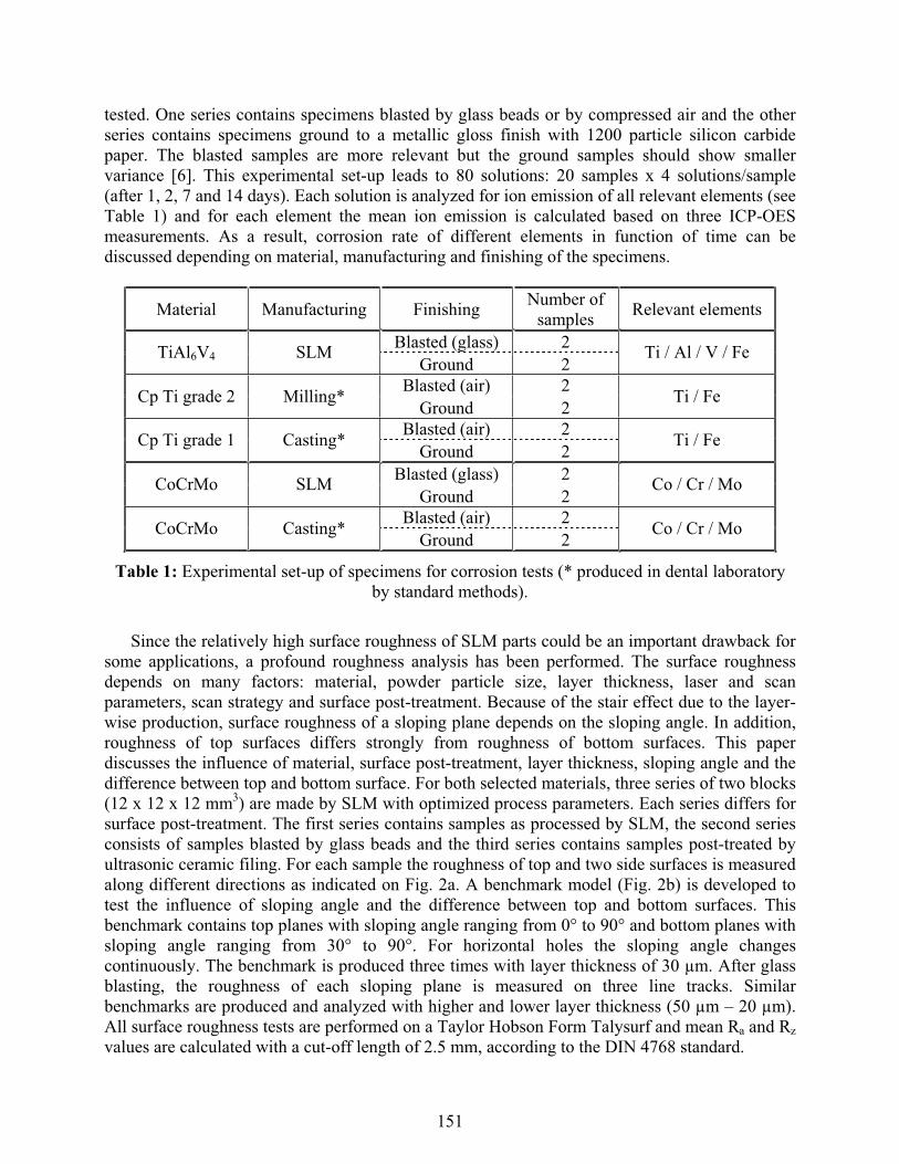
To characterize SLM with regard to process accuracy and feasibility two benchmarks aredesigned, shown on Fig. 3. Both benchmarks are produced by SLM of TiAl6V4 and after glass blasting and ultrasonic ceramic filing, dimensional analyses are performed to find out feasibleprecision. These benchmarks are not only used to characterize the process limitations, but also to optimize process parameters iteratively. Offset and scaling factors, used to compensate fordimensional changes due to the laser beam spot size and for thermal distortions due to successive melting and resolidification, are optimized based on a few loops of benchmark tests. The first benchmark model (Fig. 3a) is used to find out process accuracy in x-, y- and z-direction and to measure the accuracy of cylinders and angled features. The presence of the thin plane with a thickness of 2 mm can indicate warpage due to thermal stresses. The second benchmark model(Fig. 3b) is developed to check the feasible precision and resolution of the process by small holes (ranging from 0.5 to 3 mm diameter), small slots (ranging from 0.5 to 3 mm thickness), smallcylinders (ranging from 1 to 5 mm diameter) and thin walls (ranging from 0.5 to 3 mm thickness). Sharp edges with angles from 15° to 45° are added to the benchmark to test theinfluence of heat accumulation at the angle tips. All geometrical features of both producedbenchmarks are measured three times by tactile probes on a NC 3D coordinate measurementmachine, except for the smallest details which are measured on an optical micro-measurementmachine.
Next to fulfilling the requirements on mechanical, chemical and geometrical properties, thebreakthrough of SLM as a medical Rapid Manufacturing technique will depend on reliability,performance and economical aspects like production time and cost. These factors can not be characterized in general but will be investigated in this paper for the dental application.
a b
Fig. 3: (a) Benchmark to test process accuracy; (b) Benchmark to test feasibility of small details.
152
Results and discussion
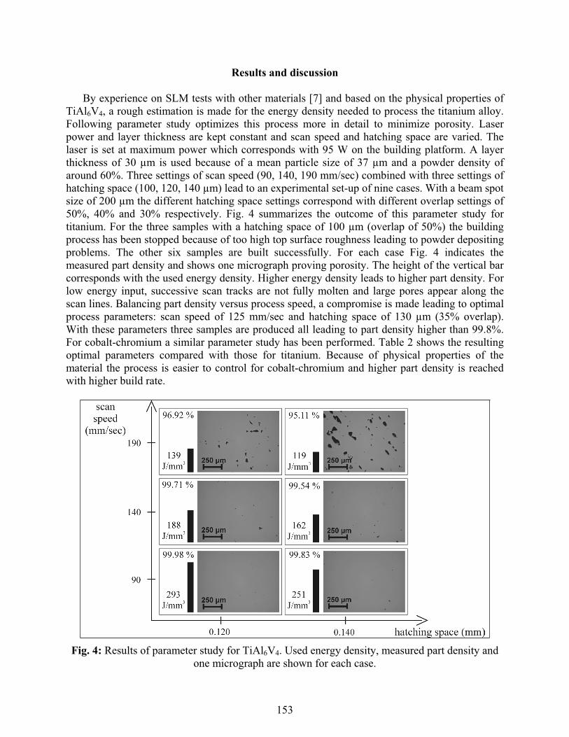
By experience on SLM tests with other materials [7] and based on the physical properties of TiAl6V4, a rough estimation is made for the energy density needed to process the titanium alloy. Following parameter study optimizes this process more in detail to minimize porosity. Laser power and layer thickness are kept constant and scan speed and hatching space are varied. The laser is set at maximum power which corresponds with 95 W on the building platform. A layerthickness of 30 μm is used because of a mean particle size of 37 μm and a powder density of around 60%. Three settings of scan speed (90, 140, 190 mm/sec) combined with three settings of hatching space (100, 120, 140 μm) lead to an experimental set-up of nine cases. With a beam spotsize of 200 μm the different hatching space settings correspond with different overlap settings of 50%, 40% and 30% respectively. Fig. 4 summarizes the outcome of this parameter study for titanium. For the three samples with a hatching space of 100 μm (overlap of 50%) the buildingprocess has been stopped because of too high top surface roughness leading to powder depositing problems. The other six samples are built successfully. For each case Fig. 4 indicates themeasured part density and shows one micrograph proving porosity. The height of the vertical bar corresponds with the used energy density. Higher energy density leads to higher part density. For low energy input, successive scan tracks are not fully molten and large pores appear along the scan lines. Balancing part density versus process speed, a compromise is made leading to optimalprocess parameters: scan speed of 125 mm/sec and hatching space of 130 μm (35% overlap).With these parameters three samples are produced all leading to part density higher than 99.8%. For cobalt-chromium a similar parameter study has been performed. Table 2 shows the resulting optimal parameters compared with those for titanium. Because of physical properties of the material the process is easier to control for cobalt-chromium and higher part density is reachedwith higher build rate.
Fig. 4: Results of parameter study for TiAl6V4. Used energy density, measured part density and one micrograph are shown for each case.
153
Material TiAl6V4 CoCrMoMelting temperature (°C) 1650 1330
Laser power (W) 95 95Layer thickness (μm) 30 40Scan speed (mm/sec) 125 200Hatching space (μm)
Overlap (%) 13035
14030
Energy density (J/mm3) 195 85Build rate (cm3/h) 1.8 4.0Part density (%) > 99.8 > 99.9
Table 2: Optimized process parameters regarding part density and process speed for titanium and cobalt-chromium.
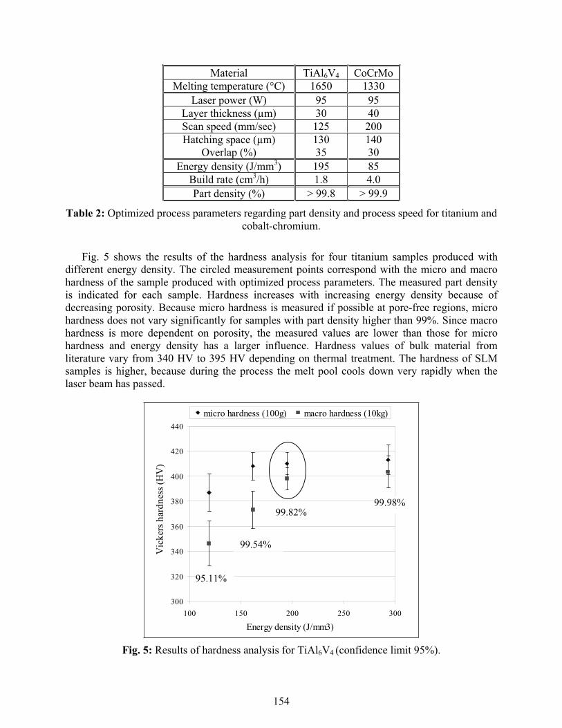
Fig. 5 shows the results of the hardness analysis for four titanium samples produced withdifferent energy density. The circled measurement points correspond with the micro and macrohardness of the sample produced with optimized process parameters. The measured part density is indicated for each sample. Hardness increases with increasing energy density because of decreasing porosity. Because micro hardness is measured if possible at pore-free regions, microhardness does not vary significantly for samples with part density higher than 99%. Since macrohardness is more dependent on porosity, the measured values are lower than those for microhardness and energy density has a larger influence. Hardness values of bulk material from literature vary from 340 HV to 395 HV depending on thermal treatment. The hardness of SLM samples is higher, because during the process the melt pool cools down very rapidly when the laser beam has passed.
300
320
340
360
380
400
420
440
100 150 200 250 300
Energy density (J/mm3)
Vic
kers
har
dnes
s(H
V)
micro hardness (100g) macro hardness (10kg)
99.98%99.82%
99.54%
95.11%
Fig. 5: Results of hardness analysis for TiAl6V4 (confidence limit 95%).
154
0
200
400
600
800
1000
1200
1400
0 1 2 3 4 5 6 7Strain (%)
Stre
ss (M
Pa)
Ultimate tensile strength: 1200-1300 MPa
Tensile Yield strength:1050-1200 MPa
E-modulus:91-96 GPa
Elongation at rupture:
5.5 - 6.3%
Fig. 6: Stress-strain graphs of tensile tests for TiAl6V4 samples.
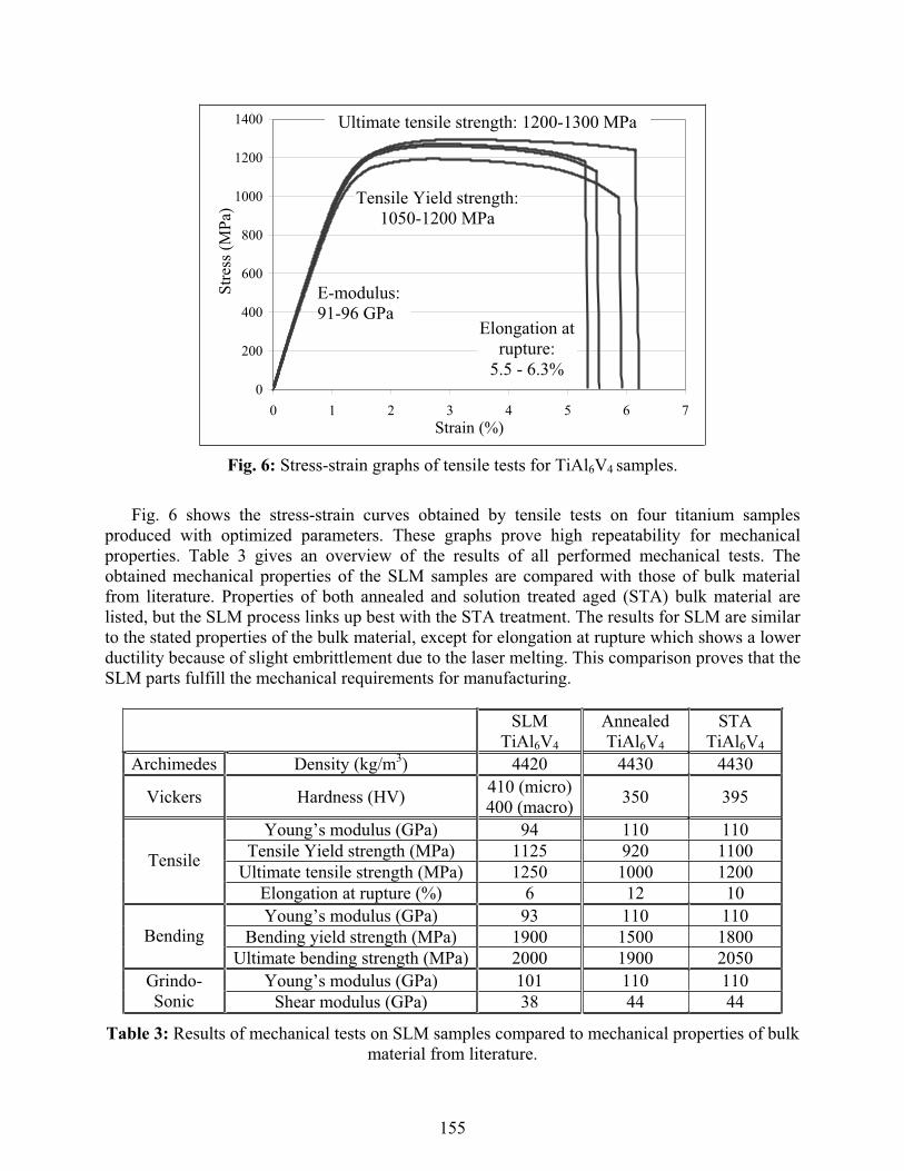
Fig. 6 shows the stress-strain curves obtained by tensile tests on four titanium samplesproduced with optimized parameters. These graphs prove high repeatability for mechanicalproperties. Table 3 gives an overview of the results of all performed mechanical tests. Theobtained mechanical properties of the SLM samples are compared with those of bulk materialfrom literature. Properties of both annealed and solution treated aged (STA) bulk material arelisted, but the SLM process links up best with the STA treatment. The results for SLM are similarto the stated properties of the bulk material, except for elongation at rupture which shows a lower ductility because of slight embrittlement due to the laser melting. This comparison proves that theSLM parts fulfill the mechanical requirements for manufacturing.
SLMTiAl6V4
AnnealedTiAl6V4
STATiAl6V4
Archimedes Density (kg/m3) 4420 4430 4430
Vickers Hardness (HV) 410 (micro)400 (macro) 350 395
Young’s modulus (GPa) 94 110 110Tensile Yield strength (MPa) 1125 920 1100
Ultimate tensile strength (MPa) 1250 1000 1200Tensile
Elongation at rupture (%) 6 12 10Young’s modulus (GPa) 93 110 110
Bending yield strength (MPa) 1900 1500 1800BendingUltimate bending strength (MPa) 2000 1900 2050
Young’s modulus (GPa) 101 110 110Grindo-Sonic Shear modulus (GPa) 38 44 44
Table 3: Results of mechanical tests on SLM samples compared to mechanical properties of bulk material from literature.
155
0
2
4
6
8
10
0 3 6 9 12 1time (days)
Co e
miss
ion
rate
(μg/
cm2*
day)
5
CoCrMo SLM blasted CoCrMo SLM groundCoCrMo cast blasted CoCrMo cast ground
a
0
1
2
0 3 6 9 12 15time (days)
Ti e
mis
sion
rate
(μg/
cm2*
day)
Ti-6Al-4V SLM blasted Ti-6Al-4V SLM groundCp Ti cast blasted Cp Ti cast groundCp Ti milled blasted Cp Ti milled ground
b
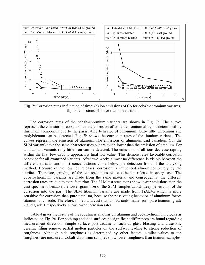
Fig. 7: Corrosion rates in function of time: (a) ion emissions of Co for cobalt-chromium variants, (b) ion emissions of Ti for titanium variants.
The corrosion rates of the cobalt-chromium variants are shown in Fig. 7a. The curves represent the emission of cobalt, since the corrosion of cobalt-chromium alloys is determined by this main component due to the passivating behavior of chromium. Only little chromium and molybdenum can be detected. Fig. 7b shows the corrosion rates of the titanium variants. Thecurves represent the emission of titanium. The emissions of aluminum and vanadium (for theSLM variant) have the same characteristics but are much lower than the emission of titanium. For all titanium variants only little iron can be detected. The emissions of all ions decrease rapidlywithin the first few days to approach a final low value. This demonstrates favorable corrosionbehavior for all examined variants. After two weeks almost no difference is visible between the different variants and most concentrations come below the detection limit of the analyzingmethod. Because of the low ion releases, corrosion is influenced almost completely by the surface. Therefore, grinding of the test specimens reduces the ion release in every case. Thecobalt-chromium variants are made from the same material and consequently, the differentcorrosion rates are due to manufacturing. The SLM test specimens show lower emissions than the cast specimens because the lower grain size of the SLM samples avoids deep penetration of the corrosion into the part. The SLM titanium variants are made from TiAl6V4 which is moresensitive for corrosion than pure titanium, because the passivating behavior of aluminum forces titanium to corrode. Therefore, milled and cast titanium variants, made from pure titanium grade2 and grade 1 respectively, show lower corrosion rates.
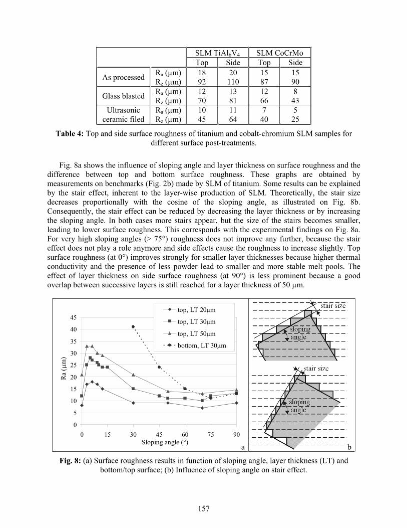
Table 4 gives the results of the roughness analysis on titanium and cobalt-chromium blocks as indicated on Fig. 2a. For both top and side surfaces no significant differences are found regarding measurement direction. Simple surface post-treatments such as glass blasting and ultrasonic ceramic filing remove partial molten particles on the surface, leading to strong reduction of roughness. Although side roughness is determined by other factors, similar values to top roughness are measured. Cobalt-chromium samples show lower roughness than titanium samples.
156
SLM TiAl6V4 SLM CoCrMoTop Side Top Side
As processed Ra (μm)Rz (μm)
1892
20110
1587
1590
Glass blasted Ra (μm)Rz (μm)
1270
1381
1266
843
Ultrasonicceramic filed
Ra (μm)Rz (μm)
1045
1164
740
525
Table 4: Top and side surface roughness of titanium and cobalt-chromium SLM samples for different surface post-treatments.
Fig. 8a shows the influence of sloping angle and layer thickness on surface roughness and the difference between top and bottom surface roughness. These graphs are obtained by measurements on benchmarks (Fig. 2b) made by SLM of titanium. Some results can be explainedby the stair effect, inherent to the layer-wise production of SLM. Theoretically, the stair size decreases proportionally with the cosine of the sloping angle, as illustrated on Fig. 8b. Consequently, the stair effect can be reduced by decreasing the layer thickness or by increasing the sloping angle. In both cases more stairs appear, but the size of the stairs becomes smaller,leading to lower surface roughness. This corresponds with the experimental findings on Fig. 8a. For very high sloping angles (> 75°) roughness does not improve any further, because the staireffect does not play a role anymore and side effects cause the roughness to increase slightly. Top surface roughness (at 0°) improves strongly for smaller layer thicknesses because higher thermalconductivity and the presence of less powder lead to smaller and more stable melt pools. The effect of layer thickness on side surface roughness (at 90°) is less prominent because a goodoverlap between successive layers is still reached for a layer thickness of 50 μm.
0
5
10
15
20
25
30
35
40
45
0 15 30 45 60 75 9Sloping angle (°)
Ra (μ
m)
0
top, LT 20μm
top, LT 30μm
top, LT 50μm
bottom, LT 30μm
a b
Fig. 8: (a) Surface roughness results in function of sloping angle, layer thickness (LT) and bottom/top surface; (b) Influence of sloping angle on stair effect.
157
Bottom or overhanging surfaces with a sloping angle below 60° have high roughness, as illustrated on Fig. 8a. Moreover, bottom surfaces with a sloping angle below 20° are not possible to make without support structures. These bottom surfaces are not finished well because of two reasons. Firstly, since the laser beam scans in loose powder instead of on solid material, thermal conductivity decreases and temperature increases leading to instable melt pools. Secondly, stalactite patterns are formed because the melt sinks in the loose powder by gravity. When overhanging surfaces with low sloping angle can not be avoided by tilting the part, specific laser parameters for the first few layers above the overhanging surface or support structures should be used. Horizontal holes, with a diameter higher than 8 mm, show bad roughness at the bottom because of the disadvantageous stair effect and at the top because of overhanging problems.
Table 5 shows the results of the dimensional analyses performed on the produced benchmarks (Fig. 3a) to test process accuracy in x-, y- and z-direction and to measure the precision of cylinders and angled features. Mean and maximum deviations between measured and designed dimensions are stated absolutely (μm) and relatively to the nominal dimension (%). The obtained accuracy fulfills the requirements of most medical and dental applications. All small features of the benchmark shown on Fig. 3b, are built successfully with high precision, except for the hole with diameter of 0.5 mm because the enclosed loose powder is melted by the surrounding heat.
Dental application
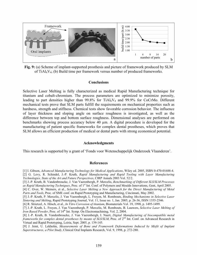
A fully digital procedure is developed for the design and manufacturing of personalized frameworks for complex dental prostheses by SLM of titanium or cobalt-chromium [8]. The framework is the metal base structure of the prosthesis and supports the artificial teeth (Fig. 9a). Such framework is screw-retained on oral implants placed in the jawbone of the edentulous patient. To avoid high stresses in the jawbone causing the oral implants to loose and to diminish the risk for colonization of bacteria resulting in infection and eventually bone loss, severe fit criteria below 40 μm are necessary at the framework-implant junctions [9]. The developed and patented procedure replaces conventional labor-intensive methods and consists of three main steps: the geometry capture of the implant positions, the digital design of the framework and the production of the framework by SLM. The procedure allows an efficient and customized manufacturing of the complex framework and guarantees the needed precision by optimal process parameters and an appropriate production strategy. The build time per framework declines for increasing number of frameworks produced during the same build, because powder depositing time is spread over all frameworks (Fig. 9b). When eight frameworks are produced during one production run, the build takes sixteen hours or two hours per framework, which is half of the build time when only one framework is produced. A lot of time and money can thus be saved by producing multiple unique frameworks in a single production run, leading to mass customization and to a lower price which competes with present-day market prices.
x-direction y-direction z-direction diameters anglesmean max mean max mean max mean max mean max
abs. (μm) 15 36 17 30 11 21 24 36 0.51° 1.33°rel. (%) 0.25 0.97 0.30 1.40 0.21 0.52 0.38 0.90 x x
Table 5: Summary of dimensional analyses performed to measure accuracy.
158
a
1:001:302:002:303:003:304:00
1 4 8 14 20number of parts
build
tim
e/pa
rt (h
:m)
b
Fig. 9: (a) Scheme of implant-supported prosthesis and picture of framework produced by SLM of TiAl6V4; (b) Build time per framework versus number of produced frameworks.
Conclusions
Selective Laser Melting is fully characterized as medical Rapid Manufacturing technique for titanium and cobalt-chromium. The process parameters are optimized to minimize porosity,leading to part densities higher than 99.8% for TiAl6V4 and 99.9% for CoCrMo. Different mechanical tests prove that SLM parts fulfill the requirements on mechanical properties such as hardness, strength and stiffness. Chemical tests show favorable corrosion behavior. The influence of layer thickness and sloping angle on surface roughness is investigated, as well as thedifference between top and bottom surface roughness. Dimensional analyses are performed on benchmarks showing process accuracy below 40 μm. A digital procedure is developed for the manufacturing of patient specific frameworks for complex dental prostheses, which proves that SLM allows an efficient production of medical or dental parts with strong economical potential.
Acknowledgments
This research is supported by a grant of ‘Fonds voor Wetenschappelijk Onderzoek Vlaanderen’.
References
[1] I. Gibson, Advanced Manufacturing Technology for Medical Applications, Wiley ed. 2005, ISBN 0-470-01688-4.[2] G. Levy, R. Schindel, J.-P. Kruth, Rapid Manufacturing and Rapid Tooling with Layer ManufacturingTechnologies, State of the Art and Future Perspectives, CIRP Annals 2003 Vol. 52/2.[3] J.-P. Kruth, B. Vandenbroucke, J. Van Vaerenbergh, P. Mercelis, Benchmarking of Different SLS/SLM Processesas Rapid Manufacturing Techniques, Proc. of 1st Int. Conf. of Polymers and Moulds Innovations, Gent, April 2005.[4] C. Over, W. Meiners, et al., Selective Laser Melting a New Approach for the Direct Manufacturing of MetalParts and Tools, Proc. of SME conf. on Rapid Prototyping and Manufacturing, Cincinnati, May 2002.[5] J.-P. Kruth, P. Mercelis, J. Van Vaerenbergh, L. Froyen, M. Rombouts, Binding Mechanisms in Selective Laser Sintering and Melting, Rapid Prototyping Journal, Vol. 11, Issue no. 1, Jan. 2005, p. 26-36, ISSN 1355-2546.[6] R. Strietzel, A. Hösch, et al., In Vitro Corrosion of titanium, Biomaterials Vol. 19, 1998, p. 1495-1499.[7] J.-P. Kruth, L. Froyen, J. Van Vaerenbergh, P. Mercelis, M. Rombouts, B. Lauwers, Selective Laser Melting ofIron Based Powder, Proc. of 14th Int. Symp. On Electromachining, Vol. 2, 2004.[8] J.-P. Kruth, B. Vandenbroucke, J. Van Vaerenbergh, I. Naert, Digital Manufacturing of biocompatible metalframeworks for complex dental prostheses by means of SLS/SLM, Proc. of 2nd Int. Conf. on Advanced Research inVirtual and Rapid Prototyping, Leiria, Sept. 2005, p. 139-145.[9] J. Jemt, U. Lekholm, Measurements of Bone and Framework Deformations Induced by Misfit of ImplantSuperstructures, a Pilot Study, Clinical Oral Implants Research, Vol. 9, 1998, p. 272-280.
159