Embed Size (px)
Citation preview
Low temperature selective laser melting of high temperature plastic powder
Toshiki NIINO and Takashi UEHARA Institute of Industrial Science, the University of Tokyo
ABSTRACT
In a typical plastic laser sintering or melting system, powder bed temperature is maintained above the recrystallization temperature of the powder material to prevent the parts under process from warping until the whole layers are processed. Although this countermeasure can elegantly suppress the part warpage, heating the powder bed to such a high temperature causes many problems. In case of high temperature plastic such as polyetheretherketone (PEEK), bed temperature should be more than 300°C. Due to this requirement, machine cost is extremely high and powder recyclability is very low. The authors had introduced another countermeasure for the part warpage that anchors the in-process parts to a rigid base plate instead of heating the powder bed above the recrystallization temperature. In the current research, application of this method to PEEK powder is tested, and a simple test piece of which relative density is more than 90% was successfully obtained with preheating temperature of 200°C. In this paper, mechanical performances of obtained parts are presented, and several problems with the process of PEEK powder are discussed as well.
INTRODUCTION
Plastic laser sintering (LS) is one of the most promising additive manufacturing processes that will be involved in direct parts manufacturing. In reality, several high value parts or products in aerospace and medical applications are produced by utilizing this technology already. Although these applications often require high performance plastics, so-called “super engineering plastics,” process of such material is not commercialized or much more expensive than those for standard materials such as PA11 and PA12. This limitation in material choice hinders the technology from expanding its application range. In the most layer manufacturing processes that obtain each layer by selective solidification of liquid or powder, one of the primary problems is part warpage caused by layer-by-layer shrinkage as the layers are consolidated and accumulated. In a typical plastic LS system, its powder bed is maintained above the recrystallization
866
temperature of the powder until the whole layers are solidified to minimize the layer-by-layer shrinks [1]. Although this anti-warp countermeasure can suppress the warpage elegantly, heating the powder bed to such a high temperature causes various problems. A normal plastic does not melt and recrystallize at points of temperature but in ranges with some widths, and the ranges are often overlapping. This overlapping leads to hard “cake,” a region of a powder bed that have not been solidified intentionally, and results in low powder recyclability. Additionally, the preheating requires LS machine with a heat resistance, and the requirement is quite high when high-temperature plastic is processed. Previously, the authors had introduced another anti-warp countermeasure that suppresses the warping by fixing the part to a rigid base plate instead of heating the powder bed to such a high temperature [2]. In the following discussion, we call this process as “low temperature process,” and normal process in which powder bed is kept above recrystallization temperature as “high temperature process.” In the current research, low temperature process of poly-etheretherketone (PEEK) super engineering plastic is preliminary tested. PEEK powder is processed with powder bed temperature of 200°C while it is more than 300°C in normal high temperature processed [3, 4]. Various parameters for consolidation of the powder is searched for, and relative density (part density) of the obtained objects are measured as primary index of their strength [5, 6]. Tensile, bending and impact tests are carried out. Mechanical performance in high temperature condition is tested as well.
MATERIAL AND METHOD
Material
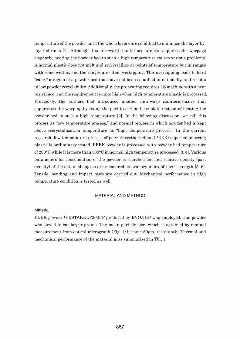
PEEK powder (VESTAKEEP200FP produced by EVONIK) was employed. The powder was sieved to cut larger grains. The mean particle size, which is obtained by manual measurement from optical micrograph (Fig. 1) became 50µm, resultantly. Thermal and mechanical performance of the material is as summarized in Tbl. 1.
867
Tbl. 1 Parameters of employed material
Type of material PEEK(Polyetheretherketone) True density 1.3 g/cm3 Bulk density 0.28 g/cm3 Average particle size 50 μm Melting point 340°C Tensile strength 100 MPa Tensile modulus 3700 MPa
Fig. 1 Optical micrograph of powder grains
Laser sintering apparatus
An experimental set up used in this research had been developed by the authors. The machine consists of building system, laser unit and their controller (Fig. 2, 3). The laser unit is installed with a CO2 laser that can generate an infrared with a wavelength of 1064µm. The maximum power at the source is 30W. Irradiated beam is focused by a dynamic focusing system equipped with Z-galvanometer into a very small spot of 130µm in diameter while it is 400 to 500µm in typical commercial systems. The spot diameter is modified or defocused by adjusting the distance between laser unit and the bed as illustrated in Fig. 4. A pair of galvanometers scans the beam in x and y direction in a range of approximately 100×100mm. The beam shoots the powder bed through a laser window of ZnSe, which seals the build chamber. The chamber is purged with nitrogen gas to inhibit the bed from oxidization. The maximum power at the bed is attenuated to 15W by transmission and reflection loss of the optics. Powder coating system employs a coating roller of which rotational and transverse speeds can be controlled independently. Two heater systems can heat surfaces of feed stock and part bed up to 200°C. In this research, the highest powder bed temperature of 200°C For the base plate a 12mm thick PEEK plate was used. Parameters of the LS apparatus is summarized in Tbl. 2
868
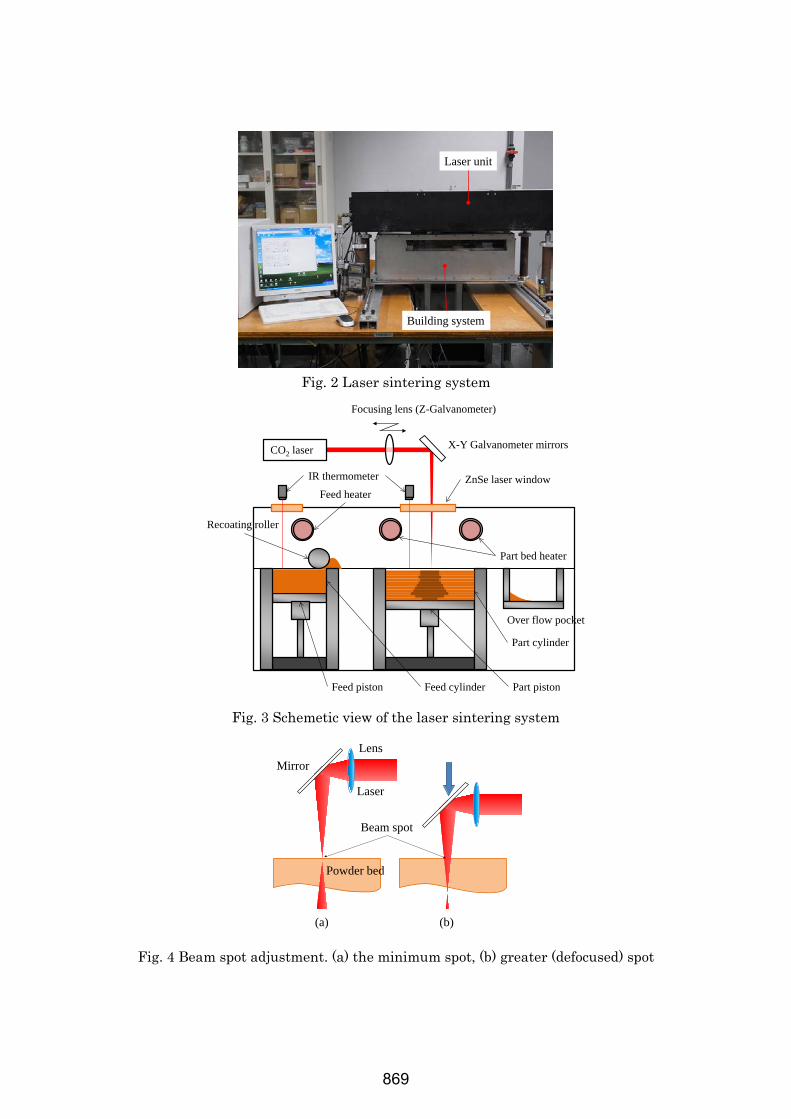
Fig. 2 Laser sintering system
Fig. 3 Schemetic view of the laser sintering system
Fig. 4 Beam spot adjustment. (a) the minimum spot, (b) greater (defocused) spot
Laser unit
Building system
CO2 laser
Focusing lens (Z-Galvanometer)
X-Y Galvanometer mirrors
ZnSe laser windowIR thermometer
Part cylinder
Part pistonFeed cylinderFeed piston
Part bed heater
Feed heater
Recoating roller
Over flow pocket
MirrorLens
Laser
Powder bed
Beam spot
(a) (b)
869
Tbl. 2 Parameters of the LS apparatus
Maximum beam power 12 W
Minimum Spot diameter 130 µm
Maximum scanning speed 3.81 m/s
Minimum scan interval 21 µm
Maximum powder bed temperature 200°C
Work volume 100 mm×100 mm×100 mm
Observation and measurement
Optical transmission observation was carried out using a digital microscope (VHX-2000 and VH-Z100, KEYENCE.) Specimens with thickness of 20µm to 50µm were prepared with large scale microtome (ERMA, INC.) Tensile test (ISO527-2) and bending test (ISO178) were performed by using multipurpose test machine (Instron 3365.) For impact test DG-UB from Toyoseiki was used. For tensile tests, a small test piece (JIS-K7161-2) was used due to part size limitation of the LS system employed in this research. For high temperature test, AG-100kNX (SHIMAZU) was used.
EXPERIMENTAL RESULTS
Minimum spot diameter and typical layer thickness
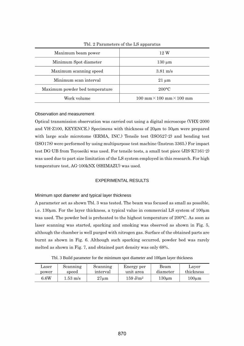
A parameter set as shown Tbl. 3 was tested. The beam was focused as small as possible, i.e. 130µm. For the layer thickness, a typical value in commercial LS system of 100µm was used. The powder bed is preheated to the highest temperature of 200°C. As soon as laser scanning was started, sparking and smoking was observed as shown in Fig. 5, although the chamber is well purged with nitrogen gas. Surface of the obtained parts are burnt as shown in Fig. 6. Although such sparking occurred, powder bed was rarely melted as shown in Fig. 7, and obtained part density was only 68%.
Tbl. 3 Build parameter for the minimum spot diameter and 100µm layer thickness
Laser power
Scanning speed
Scanning interval
Energy per unit area
Beam diameter
Layer thickness
6.6W 1.53 m/s 27µm 159 J/m2 130µm 100µm
870
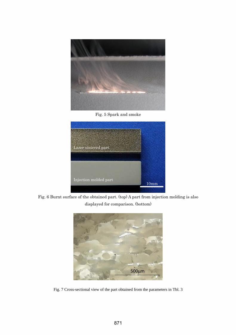
Fig. 5 Spark and smoke
Fig. 6 Burnt surface of the obtained part. (top) A part from injection molding is also
displayed for comparison. (bottom)
Fig. 7 Cross-sectional view of the part obtained from the parameters in Tbl. 3
500µm
10mm
Laser sintered part
Injection molded part
871
Effect of Defocusing
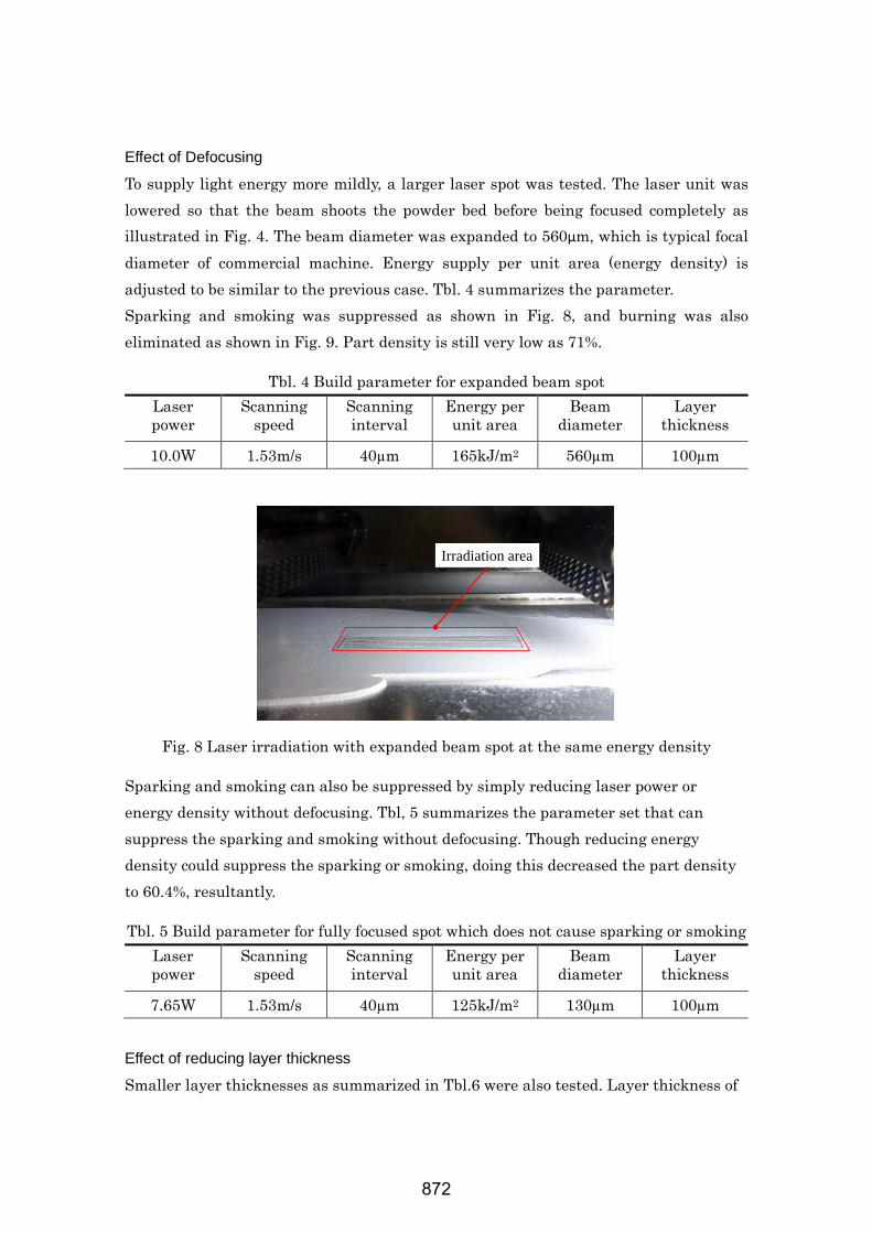
To supply light energy more mildly, a larger laser spot was tested. The laser unit was lowered so that the beam shoots the powder bed before being focused completely as illustrated in Fig. 4. The beam diameter was expanded to 560µm, which is typical focal diameter of commercial machine. Energy supply per unit area (energy density) is adjusted to be similar to the previous case. Tbl. 4 summarizes the parameter. Sparking and smoking was suppressed as shown in Fig. 8, and burning was also eliminated as shown in Fig. 9. Part density is still very low as 71%.
Tbl. 4 Build parameter for expanded beam spot Laser power
Scanning speed
Scanning interval
Energy per unit area
Beam diameter
Layer thickness
10.0W 1.53m/s 40µm 165kJ/m2 560µm 100µm
Fig. 8 Laser irradiation with expanded beam spot at the same energy density
Sparking and smoking can also be suppressed by simply reducing laser power or energy density without defocusing. Tbl, 5 summarizes the parameter set that can suppress the sparking and smoking without defocusing. Though reducing energy density could suppress the sparking or smoking, doing this decreased the part density to 60.4%, resultantly.
Tbl. 5 Build parameter for fully focused spot which does not cause sparking or smoking Laser power
Scanning speed
Scanning interval
Energy per unit area
Beam diameter
Layer thickness
7.65W 1.53m/s 40µm 125kJ/m2 130µm 100µm Effect of reducing layer thickness
Smaller layer thicknesses as summarized in Tbl.6 were also tested. Layer thickness of
Irradiation area
872
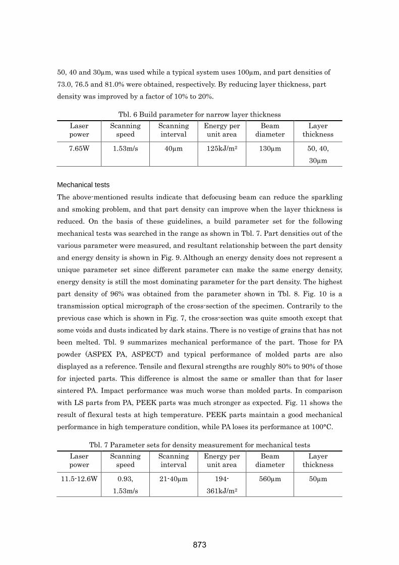
50, 40 and 30µm, was used while a typical system uses 100µm, and part densities of 73.0, 76.5 and 81.0% were obtained, respectively. By reducing layer thickness, part density was improved by a factor of 10% to 20%.
Tbl. 6 Build parameter for narrow layer thickness Laser power
Scanning speed
Scanning interval
Energy per unit area
Beam diameter
Layer thickness
7.65W 1.53m/s 40µm 125kJ/m2 130µm 50, 40, 30µm
Mechanical tests
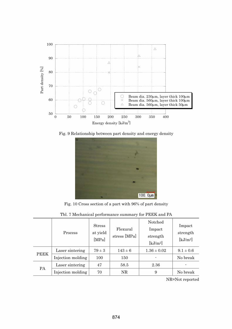
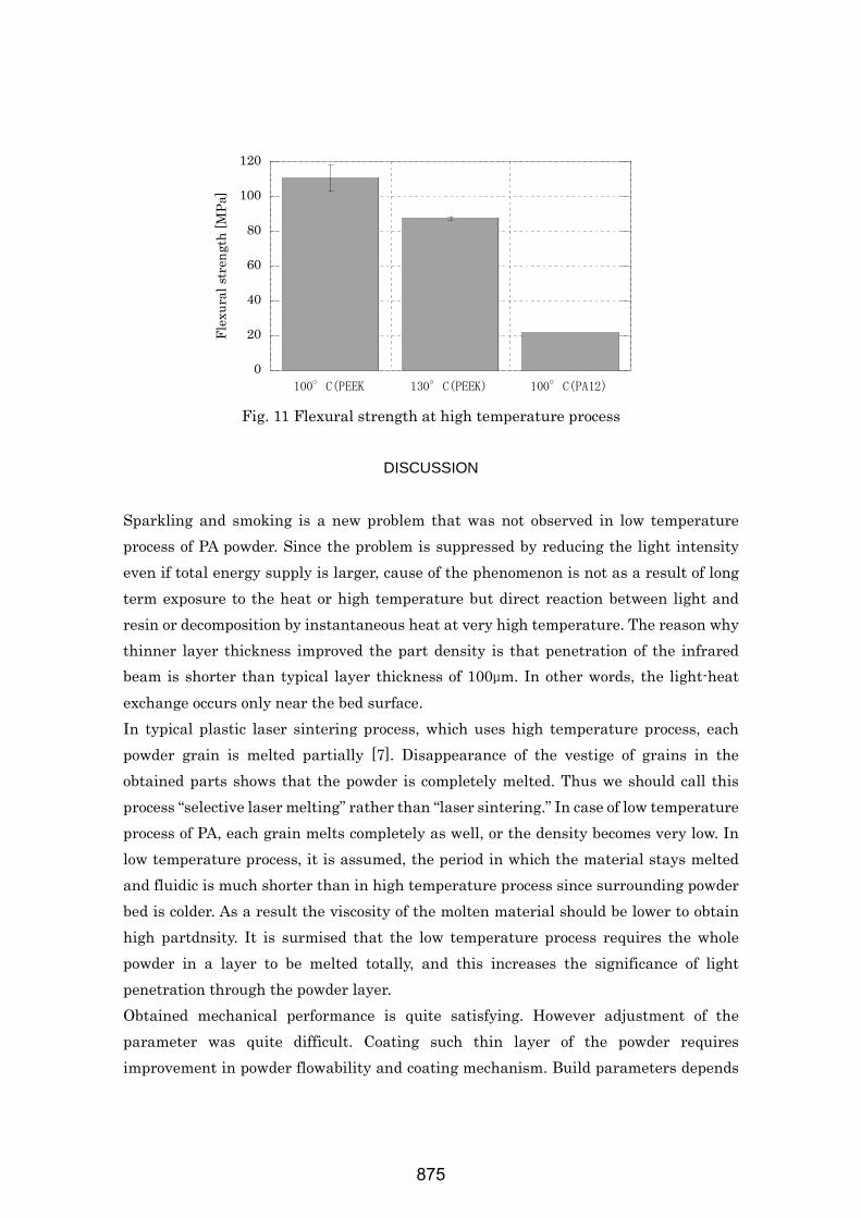
The above-mentioned results indicate that defocusing beam can reduce the sparkling and smoking problem, and that part density can improve when the layer thickness is reduced. On the basis of these guidelines, a build parameter set for the following mechanical tests was searched in the range as shown in Tbl. 7. Part densities out of the various parameter were measured, and resultant relationship between the part density and energy density is shown in Fig. 9. Although an energy density does not represent a unique parameter set since different parameter can make the same energy density, energy density is still the most dominating parameter for the part density. The highest part density of 96% was obtained from the parameter shown in Tbl. 8. Fig. 10 is a transmission optical micrograph of the cross-section of the specimen. Contrarily to the previous case which is shown in Fig. 7, the cross-section was quite smooth except that some voids and dusts indicated by dark stains. There is no vestige of grains that has not been melted. Tbl. 9 summarizes mechanical performance of the part. Those for PA powder (ASPEX PA, ASPECT) and typical performance of molded parts are also displayed as a reference. Tensile and flexural strengths are roughly 80% to 90% of those for injected parts. This difference is almost the same or smaller than that for laser sintered PA. Impact performance was much worse than molded parts. In comparison with LS parts from PA, PEEK parts was much stronger as expected. Fig. 11 shows the result of flexural tests at high temperature. PEEK parts maintain a good mechanical performance in high temperature condition, while PA loses its performance at 100°C.
Tbl. 7 Parameter sets for density measurement for mechanical tests Laser power
Scanning speed
Scanning interval
Energy per unit area
Beam diameter
Layer thickness
11.5-12.6W 0.93, 1.53m/s
21-40µm 194-361kJ/m2
560µm 50µm
873
50
60
70
80
90
100
0 50 100 150 200 250 300 350 400
Beam dia. 230µm, layer thick 100µmBeam dia. 560µm, layer thick 100µmBeam dia. 560µm, layer thick 50µm
Part
den
sity
[%]
Energy density [kJ/m2]
Fig. 9 Relationship between part density and energy density
Fig. 10 Cross section of a part with 96% of part density
Tbl. 7 Mechanical performance summary for PEEK and PA
Process Stress
at yield [MPa]
Flexural stress [MPa]
Notched Impact
strength [kJ/m2]
Impact strength [kJ/m2]
PEEK Laser sintering 79 ± 3 143 ± 6 1.36 ± 0.02 9.1 ± 0.6
Injection molding 100 150 - No break
PA Laser sintering 47 58.5 2.36 -
Injection molding 70 NR 9 No break NR=Not reported
874
0
20
40
60
80
100
120
100°C(PEEK 130°C(PEEK) 100°C(PA12)
Flex
ural
stre
ngth
[MPa
]
Fig. 11 Flexural strength at high temperature process
DISCUSSION
Sparkling and smoking is a new problem that was not observed in low temperature process of PA powder. Since the problem is suppressed by reducing the light intensity even if total energy supply is larger, cause of the phenomenon is not as a result of long term exposure to the heat or high temperature but direct reaction between light and resin or decomposition by instantaneous heat at very high temperature. The reason why thinner layer thickness improved the part density is that penetration of the infrared beam is shorter than typical layer thickness of 100µm. In other words, the light-heat exchange occurs only near the bed surface. In typical plastic laser sintering process, which uses high temperature process, each powder grain is melted partially [7]. Disappearance of the vestige of grains in the obtained parts shows that the powder is completely melted. Thus we should call this process “selective laser melting” rather than “laser sintering.” In case of low temperature process of PA, each grain melts completely as well, or the density becomes very low. In low temperature process, it is assumed, the period in which the material stays melted and fluidic is much shorter than in high temperature process since surrounding powder bed is colder. As a result the viscosity of the molten material should be lower to obtain high partdnsity. It is surmised that the low temperature process requires the whole powder in a layer to be melted totally, and this increases the significance of light penetration through the powder layer. Obtained mechanical performance is quite satisfying. However adjustment of the parameter was quite difficult. Coating such thin layer of the powder requires improvement in powder flowability and coating mechanism. Build parameters depends
875
very much on various conditions such as parts shapes, their arrangement in the bed and scan pattern. More investigation is still required for practical use of this technology. Powder bed temperature of 200°C is easy to achieve from the view point of machine development, and this means that the low temperature process can facilitate the laser “melting” of high performance plastic in the near future.
ACKNOWLEDGEMENTS
This research is supported by “Strategic Innovation Promotion Program” Cabinet Office, Government of Japan.
CONCLUSIONS
PEEK powder was successful processed with low powder bed temperature of 200°C. Heat resistance against the temperature is achieved relatively easy, and the result indicates that PEEK can be processed practically in the near future. Sparking and smoking phenomena were observed, but the problem can be avoided by reducing light intensity of the laser. Part density reached a high value of 96%, which is standard value of commercialized process for PA powder. Reduction of mechanical performances from those of typical injection molded parts is around 10 to 20%. This reduction is almost the same as the case of PA powder. Additionally, good performance is obtained in a high temperature condition as well. Various conditions such as shape of objects, their arrangement and scan pattern affect the performance of the parts. These problems are remaining to be solved in the future.
REFERENCES
[1] Beaman, et al, “Solid Freeform Fabrication: A New Direction in Manufacturing,” (1996)
[2] Niino et al, “Feasibility study on plastic laser sintering without powder bed preheating,” Proc.
Solid Freeform Fabrication Symposium 2011 (2011) 17-29
[3] Schmidt, M., Pohle, D., Rechtenwald, T, “Selective laser sintering of PEEK,” CIRP Annals-
Manufacturing Technology, 56, 1 (2014) p205-208 (2014)
[4] Kroh, M., Bonten, C., Eyerer, P, “Improvement of mechanical properties by additive assisted
laser sintering of PEEK,” AIP Conference Proceedings, v 1593, p 724-727, 2014, Proceedings of
PPS 2013 - 29th International Conference of the Polymer Processing Society, Conference Papers
[5] Niino et al, “Microstructural Observation and Mechanical Property Evaluation of Plastic Parts
876
Obtained by Preheat Free Laser Sintering,” Proc. Solid Freeform Fabrication Symposium 2012
(2012) 617-628
[6] Majewski et al, “Effect of section thickness and build orientation on tensile properties and
material characteristics of laser sintered nylon-12 parts” Rapid Prototyping Journal, v 17, n 3, p
176-180, 2011
[7] Zarringhalam et al, “Degree of particle melt in Nylon-12 selective laser-sintered parts,” Rapid
Prototyping Journal, 15 (2009) 126-132
877


![Two Different Strategies to Enhance Osseointegration in ...selective electron beam melting [8,9], rapid prototyping [10,11], powder metallurgy (PM) [11–14], selective laser melting](https://img.pdfslide.us/doc/110x75/611db5b0f1fafb782f3cd5e4/two-different-strategies-to-enhance-osseointegration-in-selective-electron-beam.jpg)