Embed Size (px)
Citation preview

SEISMIC STABILITY EVALUATIONS OF CHESBRO, LENIHAN, STEVENS CREEK, AND UVAS DAMS
(SSE2)
PHASE A: STEVENS CREEK AND LENIHAN DAMS
SITE INVESTIGATIONS AND LABORATORY TESTING AT STEVENS CREEK DAM
WORK PLAN
Prepared for
SANTA CLARA VALLEY WATER DISTRICT 5750 Almaden Expressway San Jose, CA 95118 November 2010

WORK PLAN FOR SITE INVESTIGATIONS AND LABORATORY TESTING AT STEVENS CREEK DAM
SSE2-WP-1SC Final.docx i
TABLE OF CONTENTS
1.0 Introduction ........................................................................................................... 1
2.0 Summary of Dam and Foundation Conditions ...................................................... 1
3.0 Key Geotechnical Issues in Seismic Stability Evaluation ...................................... 2
4.0 Local Seismotectonic Setting and Ground Motions .............................................. 3
5.0 Previous Investigations ......................................................................................... 4
6.0 Geologic Model of Foundation Conditions ............................................................ 5
6.1 General Approach ................................................................................................... 5 6.2 Inferred Distribution of Foundation Materials ........................................................ 6
7.0 Results of Preliminary Engineering Analyses ....................................................... 8
8.0 Proposed Exploration, Testing and Instrumentation ............................................. 9
9.0 Field Personnel and Specialty Contractors ......................................................... 12
10.0 Procedures for Geotechnical Drilling and Sampling ........................................... 13
11.0 Procedures for Piezometer Installation ............................................................... 14
11.1 Casagrande Piezometers ....................................................................................... 14 11.2 Vibrating Wire Piezometers .................................................................................. 15
12.0 Laboratory Testing .............................................................................................. 16
13.0 Schedule ............................................................................................................ 17
14.0 Environmental Considerations ............................................................................ 17
15.0 References ......................................................................................................... 17
Tables
1 Aerial Photographs 2 Dam Foundation Elevation Data
Figures
1 Footprint of Stevens Creek Dam and Plan of Previous Explorations
2 Cross Sections – Stevens Creek Dam
3 Design Response Spectrum and Matched Time Histories
4 Estimated Thickness of Soils Left in Place – Stevens Creek Dam
5 Geologic Mapping – Stevens Creek Dam
6 Cross Section at Station 7+50 and Mesh for FLAC Analyses
7 Upstream Displacement Contours and Berm Crest Displacement Time History
8 Downstream Crest Displacements vs Shear Strength of Alluvium

WORK PLAN FOR SITE INVESTIGATIONS AND LABORATORY TESTING AT STEVENS CREEK DAM
SSE2-WP-1SC Final.docx ii
9 Final Subsurface Exploration Plan – Stevens Creek Dam
10 Proposed Explorations – Stevens Creek Dam
11 Design of Temporary Access Road – Stevens Creek Dam

WORK PLAN FOR SITE INVESTIGATIONS AND LABORATORY TESTING AT STEVENS CREEK DAM
SSE2-WP-1SC Final.docx 1
1.0 INTRODUCTION
Terra / GeoPentech (TGP), a joint venture of Terra Engineers, Inc. and GeoPentech, Inc., has been retained by the Santa Clara Valley Water District (District) to complete seismic stability evaluations for Chesbro, Lenihan, Stevens Creek and Uvas Dams (SSE2). Phase A of the project includes work on Stevens Creek and Lenihan Dams and has a planned completion date of December 2011. Phase B of the project includes work on Chesbro and Uvas Dams and is scheduled to begin in January 2012 and to finish by the end of 2013.
This document presents the work plan for site investigations and laboratory testing at Stevens Creek Dam and includes the following sections:
2.0 – Summary of Dam and Foundation Conditions 3.0 – Key Geotechnical Issues for Seismic Stability 4.0 – Local Seismotectonic Setting 5.0 – Previous Investigations 6.0 – Geologic Model of Foundation Conditions 7.0 – Results of Preliminary Seismic Deformation Analyses 8.0 – Proposed Exploration, Testing and Instrumentation 9.0 – Field Personnel and Specialty Contractors 10.0 – Procedures for Geotechnical Drilling and Sampling 11.0 – Procedures for Piezometer Installation 12.0 – Laboratory Testing 13.0 – Schedule 14.0 – Environmental Considerations 15.0 – References
The development of a geologic model of the foundation conditions based on comprehensive review of all available data and geologic site reconnaissance (Section 6.0), and the preliminary seismic deformation analyses (Section 7.0), represent a considerable amount of new work that has allowed the work plan to be focused on providing the supplemental data that is specifically needed to address the key geotechnical issues for the seismic stability evaluation.
2.0 SUMMARY OF DAM AND FOUNDATION CONDITIONS
The original embankment of Stevens Creek Dam was designed as a two-zone earthfill dam, with an "impervious" upstream zone and a "pervious" downstream zone. Subsequent studies have indicated that the dam may in fact be more like a homogenous embankment. A cutoff trench was constructed at about the midpoint of the upstream impervious zone by excavating through the overburden soils and into the Santa Clara Formation. The Santa Clara Formation is a poorly indurated conglomerate with lesser interbeds of sandstone, siltstone and claystone - it is essentially a very dense clayey gravel. Seismic stability evaluations of the dam were performed in the late 1970s and concluded that a Maximum Credible Earthquake on the San Andreas fault could cause the dam to fail due to excessive deformation. As a result, stabilizing buttress sections were constructed in 1985 on the upstream and downstream slopes, with an inclined filter and drain placed between the original downstream slope and the new buttress fill. Figure 1 is an

WORK PLAN FOR SITE INVESTIGATIONS AND LABORATORY TESTING AT STEVENS CREEK DAM
SSE2-WP-1SC Final.docx 2
aerial photograph of Stevens Creek Dam that shows the location of the previous explorations and the horizontal station numbers along the new crest of the dam. Figure 2 shows transverse sections through the current configuration of the dam at the maximum section (Station 7+50) and at Station 9+70 on the left side of the dam.
The locations of existing piezometers are also shown on Figure 2. Nine pneumatic piezometers were installed in 1986 following the construction of modifications; two of these (B-3 and B-6) are set in the dam foundation. One seepage weir was also installed following the modifications at the downstream toe to measure flow from the inclined filter/drain and toe blanket drain; however, the drain is founded on alluvium and thus, some unknown amount of the total seepage through the embankment may be passing through the underlying alluvial soils beneath the weir.
The foundation beneath the dam downstream of the cutoff trench includes older alluvial terrace deposits (mostly sands and gravels with varying amounts of fines), with some colluvium on the mid and upper abutments. Younger alluvial deposits (mostly sandy and silty gravels and some sand layers) underlie the channel section of the foundation downstream of the cutoff. Santa Clara Formation bedrock underlies the outlet pipe and overburden soils were generally removed from beneath the upstream “impervious” embankment zone and from the deeper cutoff trench located beneath the center of the upstream “impervious” embankment zone. In addition, a minimum 50-foot wide strip of the upstream buttress foundation is underlain by Santa Clara Formation bedrock. Some younger alluvium also appears to underlie the upstream portion of the original embankment (upstream of the cutoff trench) and the downstream margin of the upstream buttress. Details of our recent analysis of the distribution of the various foundation materials underlying the dam are presented in Section 6.0.
3.0 KEY GEOTECHNICAL ISSUES IN SEISMIC STABILITY EVALUATION
The strength and stiffness of the compacted embankment materials have been reasonably well characterized by previous investigations. The key geotechnical issues in the seismic stability evaluation involve evaluation of the liquefaction potential, shear strength and stiffness of the soils left in place beneath the dam during seismic loading. These parameters are dependent on the initial effective stresses and possibly on the short term drainage conditions in the alluvium beneath the dam and in the embankment foundation materials surrounding the alluvium. The initial effective stresses can be evaluated based on the distribution of piezometric levels and associated seepage forces in the embankment. In particular, the following information concerning the state of the dam and its foundation is necessary to complete the seismic stability evaluation:
1. The areal extent and thickness of soils left in place between the base of the dam embankment and the bedrock;
2. The liquefaction potential and residual strength of the soils left in place beneath the dam;
3. The ability of the soils left in place to accommodate dynamic drainage and reduce the potential for the buildup of pore pressure in the alluvium as a result of earthquake loading;
4. The ability of the soils left in place to act as a horizontal drainage layer beneath the embankment as evidenced by piezometric levels within these soils;

WORK PLAN FOR SITE INVESTIGATIONS AND LABORATORY TESTING AT STEVENS CREEK DAM
SSE2-WP-1SC Final.docx 3
5. The distribution of piezometric levels (and direction of seepage forces) within the dam embankment; and
6. The engineering properties of the embankment materials.
The potential for liquefaction of the younger alluvial deposits underlying the maximum section of the embankment downstream of the foundation cutoff trench has not been previously well evaluated. This is also the case with the older alluvial terrace and channel deposits that are known to underlie at least portions of the downstream left abutment, and probably most of the area of the mid-upper level right abutment foundation, downstream of the cutoff.
Our work included review of reports provided by the District; review of information contained in District archives to identify reports, correspondence, aerial photographs, and construction records not previously provided by the District; and review of the file on Stevens Creek Dam maintained at the office of the State of California, Department of Water Resources, Division of Safety of Dams (DSOD). The reviews of District files were made on June 23, June 24 and July 14, 2010, and the review of DSOD files was made on June 30. 2010. Our review of data from previous studies and construction inspection reports, along with observations made during our recent field reconnaissance of the dam site, indicate that much of the alluvium probably contains a significant gravel fraction, and thus may not have been accurately characterized by the limited exploration data obtained during previous studies.
With respect to initial effective stresses, current piezometric instrumentation is mostly located within the embankment and drainage zones, with two piezometers set into the foundation. Piezometer B-3 is set in the channel section foundation, but it is unclear whether it is installed in the alluvium or within the underlying Santa Clara Formation bedrock, given its elevation relative to the potential top of bedrock surface that has been modeled as part of our work and is further discussed in Section 6.0 of this work plan. Apparently, no boring logs of the existing piezometers were produced during their installation following the dam modifications in 1986. However, it is clear that the other foundation piezometer, B-6, is set in the Santa Clara Formation bedrock. Consequently, the location of the piezometric surface within the foundation alluvium is presently not well defined. However, the embankment piezometers show there is a well-defined downward gradient. This downward gradient (and the associated downward seepage force) is very important because it causes a significant increase in vertical effective stress and a corresponding increase in the shear strength of the embankment materials.
4.0 LOCAL SEISMOTECTONIC SETTING AND GROUND MOTIONS
The recent Seismotectonic and Ground Motion Study for Seismic Stability Evaluation of DIP Phase 1 Dams (AMEC, 2009) indicates that the San Andreas, Berrocal, and Stanford-Monte Vista faults are the controlling seismic sources at Stevens Creek Dam. According to AMEC, the Stanford-Monte Vista earthquake (M6.9 @ 2.4 km northeast of the dam) produces the highest accelerations at short periods whereas the San Andreas earthquake (M 7.9 @ 4.2 km southwest of the dam) dominates at longer periods. DSOD has indicated in their recent comments on the SSE-1 Investigations DM-2 and Interim DM-4 for Guadalupe, Almaden, and Calero Dams (DSOD, 2010) that they have considered a combined rupture of the Shannon – Monte Vista faults (DSOD, 2010), in contrast to the Stanford-Monte Vista fault rupture scenario of AMEC.

WORK PLAN FOR SITE INVESTIGATIONS AND LABORATORY TESTING AT STEVENS CREEK DAM
SSE2-WP-1SC Final.docx 4
However, the maximum moment magnitude of M7 assigned by DSOD to the Shannon - Monte Vista earthquake closely approximates the M6.9 estimate by AMEC for the Stanford – Monte Vista earthquake. The Berrocal and Stanford-Monte Vista faults are both west-dipping reverse faults and are located to the southwest and northeast of the dam, respectively. The dam is therefore located on a block of rock that forms the footwall of the Berrocal fault and the hanging wall of the Stanford-Monte Vista fault.
Our review of data related to the seismologic and tectonic conditions in the region of Stevens Creek Dam found no indications of tectonic deformation in the immediate vicinity of the dam. No faults are shown passing through, or in the immediate vicinity of, the dam site on the AMEC 2009 maps or on earlier USGS and CDMG maps. No faulting of the east-dipping Santa Clara Formation beds was noted at the dam site during construction, and no linear features were noted crossing the dam site on the aerial photographs (SCVWD, 2010c) we reviewed.
The design response spectrum used in the preliminary engineering analyses discussed in Section 7.0, corresponding to the envelope of the 84th percentile response spectra from the Stanford-Monte Vista and San Andreas events as provided in the AMEC report (AMEC, 2009), is shown on the left side of Figure 3. The Lucerne record from the Landers earthquake was selected as seed input motion to the current evaluation. The matched time histories (acceleration, velocity and displacement) and the corresponding response spectrum are shown on right side of Figure 3. It is noted that the acceleration time histories shown on right side of Figure 3 are considered adequate only for the purposes of the current preliminary analyses. The final analyses will be completed with three acceleration-time histories to be approved by DSOD with appropriate consideration of both the maximum earthquake spectra shown for earthquakes on both the Stanford–Monte Vista (as per AMEC 2009) and the San Andreas faults. Also, it is noted that the shaking levels associated with both these maximum earthquakes are high enough that if the alluvium is found to be susceptible to liquefaction, it likely would liquefy. Therefore, for the current preliminary analyses, we are focusing on the estimated residual strength of the alluvium, assuming the alluvium has the potential to liquefy.
5.0 PREVIOUS INVESTIGATIONS
The first significant post-construction investigations at Stevens Creek Dam were conducted by Woodward-Clyde Consultants (WCC) who completed a Seismic Stability Assessment in 1976 as part of an investigation of four Santa Clara Valley Water District dams (WCC, 1976b). WCC drilled eight borings, six of which were logged and extended into Santa Clara Formation bedrock. They also performed cross-hole shear wave tests in three of the borings, installed two open-well piezometers in the embankment, and performed limited index properties testing. WCC concluded they could not make a meaningful seismic stability evaluation with their data because they were unable to obtain cyclic strength data.
Shannon & Wilson, Inc. (S&W) installed seven piezometers in 1976 (S&W, 1976); one of these (A-3) was apparently installed in the alluvial foundation under the downstream embankment zone. S&W also performed very limited laboratory testing.
More significant field and laboratory investigations commenced with the Seismic Safety Evaluation study in 1978 by Wahler Associates (Wahler) that was followed by their 1982

WORK PLAN FOR SITE INVESTIGATIONS AND LABORATORY TESTING AT STEVENS CREEK DAM
SSE2-WP-1SC Final.docx 5
Preliminary Remedial Design Investigation, and then by their final Remedial Design Report in 1984 (Wahler, 1978, 1982, and 1984). In all, Wahler performed:
1. logging of two large diameter borings with down-hole logging and 6-inch diameter Pitcher Barrel sampling; one of these extended into the Santa Clara Formation bedrock;
2. logging of four trenches with in-place density testing of embankment, terrace and younger alluvium materials;
3. logging of ten rotary borings in the dam, some with frequent Pitcher Barrel sampling; only two of these appear to have extended into bedrock;
4. a large number of classification and engineering properties testing including permeability, UU, ICU, ICD and cyclic triaxial tests;
5. two sets of cross-hole shear wave tests; and
6. logging of many test pits and borings in the borrow area.
Wahler also functioned as resident engineer and provided observation and testing services during construction of the dam modifications in 1985-86. A summary of their field density tests, which included in-situ density testing of the alluvial foundation underlying the new outlet structure, was located during our review of DSOD files. As-built sections of the upstream buttress were also located during our review of District files.
All of the above data has been consolidated and reviewed as part of our work. In addition, six sets of black and white stereo aerial photographs were reviewed at the District’s office. These photo sets are dated 11/04/1969, 3/31/1983, 6/19/1985, 11/20/1985, 1/10/1986, and 11/05/2002 (SCVWD, 2010c), and are presented on Table 1. The three sets from 1985-1986 span the period of the buttress construction and show the dam in various stages of modification with the reservoir area mostly drained.
A list of documents we reviewed while preparing this work plan is presented in Section 15.0.
6.0 GEOLOGIC MODEL OF FOUNDATION CONDITIONS
6.1 General Approach
We prepared a working geotechnical base map for the original dam and the dam modifications made in 1985-1986 that includes topographic contours of the top of embankment foundation materials (i.e. the base of the embankment) and estimated topographic contours of the top of Santa Clara Formation (bedrock). These surfaces were then combined to produce the isopach map included as Figure 4 that shows the estimated distribution and thickness of the alluvium and colluvium that underlies the embankment. We have also prepared a geologic map of the dam site area (Figure 5) that is based on a geologic reconnaissance integrated with the general distribution of dam foundation materials shown on Figure 4. The geologic map in Figure 5 is more schematic than the isopach map of Figure 4 and differs from Figure 4 in some details. However, these figures are sufficiently accurate for the purposes of this work plan. Both Figures 4 and 5 will be updated based on the results of the field and laboratory investigations and the detailed site characterization studies that will follow the field investigations.

WORK PLAN FOR SITE INVESTIGATIONS AND LABORATORY TESTING AT STEVENS CREEK DAM
SSE2-WP-1SC Final.docx 6
The basic approach for preparing Figure 4 was to supplement the digitized as-built foundation contour map provided by the District (SCVWD, 2010d) with the geotechnical data obtained during the subsurface investigations completed after the original dam was built. These data were obtained from borings and test pit logs by WCC, S&W and Wahler, and also include information on the configuration of the upstream buttress foundation as depicted on the as-built sections prepared by Wahler in 1986. Special attention was paid to converting all the elevation data on previous maps and field explorations to the currently used NAVD 1988 vertical datum. The original design drawings, and the WCC and S&W studies, were based on a local vertical datum that was converted to NAVD 1988 vertical datum by adding 0.6 feet. The Wahler investigations data were based on the USGS 1929 vertical datum and were converted to NAVD 1988 vertical datum by adding 2.8 feet.
The data summarized in Table 2 includes foundation surface elevations (at the top of the underlying alluvium, colluvium or Santa Clara Formation bedrock) and the elevations of the top of the Santa Clara Formation bedrock where encountered in the borings. For the purpose of utilizing the previous data to prepare the base maps, we assumed that geologic interpretations presented on the previous exploration logs were correct. The as-built foundation surface contours were then locally adjusted where required to accurately reflect the elevations of contacts as indicated on the previous boring and trench logs. New contours were drawn for the upstream buttress foundation outside the footprint of the original dam based on the Wahler as-built sections for that area (Wahler, 1986a).
A digitized pre-construction topographic map of the dam site was also provided by the District (SCVWD, 2010e). We used this pre-construction topographic map to estimate the top of the Santa Clara Formation bedrock in the areas of the dam located downstream of the cutoff. Elevations of top of bedrock between the original dam cutoff trench and the base of the approximately 50-foot wide cutoff trench through the alluvium that underlies the 1986 upstream buttress were estimated based on Wahler as-built sections showing the level of the top of rock under the buttress. The areas of the dam foundation estimated to be directly underlain by Santa Clara Formation are shown in plan on both Figures 4 and 5, and in profile on Figure 2 on dam sections at Stations 7+50 and 9+70.
6.2 Inferred Distribution of Foundation Materials
The results of our integration of the reconnaissance mapping, previous exploration data, pre-construction topographic survey, as-built topographic surfaces of the foundation of the original embankment, Wahler as-built sections of the upstream buttress, and DSOD construction inspection reports from 1935-1936 and 1985-1986, indicate the following:
1. The areas of thickest alluvium are probably concentrated under the Stevens Creek channel portion of the embankment foundation, downstream of the cutoff trench. The outlet structure was founded on alluvium, as was the extended outlet from a point 30 feet downstream of the original toe to the outlet structure (Wahler 1986b and DSOD 1985-1986, respectively). Our analysis suggests that perhaps up to approximately 20 feet of alluvium might underlie the downstream portion of the maximum section of the embankment, which is not inconsistent with the measured alluvial thickness of 15 feet in WCC Boring 5 that was drilled into that area of the foundation.

WORK PLAN FOR SITE INVESTIGATIONS AND LABORATORY TESTING AT STEVENS CREEK DAM
SSE2-WP-1SC Final.docx 7
2. Comparison of the pre-construction topographic survey and the as-built topography survey of the foundation of the original dam provided by the District indicate that minimal excavation was performed downstream of the foundation cutoff over most of the right abutment and channel areas (except for the steeper lower abutment slope leading down to the outlet trench excavation on the right side of the channel area). This conclusion is corroborated by Wahler Boring SC-1 near the right end of the dam, which encountered approximately 4 feet of slightly organic topsoil (silty sand) overlying 8 feet of clayey alluvial terrace gravels.
3. Original dam construction inspection reports by State inspector G.F. Engle indicate that the contractor had initially requested approval for fill placement on portions of the downstream foundation that was denied because of inadequate stripping (organics, trees, etc. were reportedly left in-place). Although Engle indicates that the prepared foundation surfaces were eventually accepted, this does suggest that excavation downstream of the upstream “impervious zone” was probably minimal.
4. Engle also indicates that the entire foundation area of the embankment upstream of the contact between the “pervious” and “impervious” zones (along a line located a short distance downstream of the cutoff trench) was excavated down to Santa Clara Formation bedrock. This however is not corroborated by the Wahler (1986a) as-built sections of the upstream buttress, which show that an area of alluvium was left underlying the upstream zone of the original dam, upstream of the cutoff. The extent of the alluvial soils left in place, between the core trench and the cutoff trench through the alluvium for the upstream buttress, is shown on Figures 2, 4 and 5.
5. The Wahler (1986a) as-built sections indicate that this upstream area of alluvium also underlies a relatively narrow downstream portion of the upstream buttress (see Figures 2, 4 and 5). This configuration was required because complete removal of the alluvium beneath the entire buttress footprint would have required undercutting the original dam toe. In their records, DSOD noted that this approach was a change in the specified foundation design criteria that called for the entire upstream buttress to be founded on Santa Clara Formation bedrock. However, DSOD accepted founding the buttress on marginal areas of alluvium provided that a minimum 50-foot width of the buttress was founded on bedrock. This configuration is shown on the Wahler as-built sections and also indicated by the distribution of Santa Clara Formation bedrock in the upstream foundation area on Figures 2, 4, and 5. It should also be noted that the 1985-1986 DSOD inspection reports indicate that both the methods used to construct the dam modifications, and Wahler’s supervision of the work, appeared to be well done.
6. We have noted that the minimal downstream excavation depths indicated by our analysis are in contrast to the estimated depths of excavation shown on Figure 7 of the District’s Foundation Analysis Report of SSE-2 Dams (SCVWD, 2010a). That figure shows 4 to 5 feet of excavation at the location of Boring SC-1, with 0 foot of estimated surface soils left in place over that area of the upper right abutment footprint, as shown on Figure 11 of the report. As noted above, Boring SC-1 indicates an aggregate thickness of 13 feet of in-place surficial soils at that location (top soil/colluvium and terrace gravel). We have also noted that the depths of excavation shown for the right abutment cutoff trench shown on Figure 7 of the District’s report appear inconsistent with the depth of the cutoff trench as indicated by
WORK PLAN FOR SITE INVESTIGATIONS AND LABORATORY TESTING AT STEVENS CREEK DAM
SSE2-WP-1SC Final.docx 8
the as-built foundation topography provided by the District (i.e., the District’s Figure 7 shows considerably less excavation along the cutoff trench than is depicted by the as-built topography).
7. It does appear that somewhat more excavation may have occurred over portions of the mid-slope area of the downstream left abutment foundation, although 10 feet of alluvial soils over bedrock were encountered in WCC Borings 1 and 2 on the upper left abutment. The presence of alluvial deposits remaining within the foundation in this area is not surprising since original dam construction reports by Engle indicate that open-graded terrace gravel channels were encountered on the upper left abutment and required local deepening of the cutoff trench. The presence of upper level terrace gravels on the left abutment is also consistent with our reconnaissance geologic mapping and earlier mapping of the area by Jim Vantine in 1972 as part of a landslide mapping investigation for the District (SCVWD, 1976). Both studies show the presence of older alluvial gravels on the boat launch peninsula just upstream of the dam on the west side of the reservoir, with Vantine’s mapping showing the base of the deposit at about Elevation 500 feet (approximately the same elevation where the cutoff trench began deepening on the uppermost left abutment).
Based on the foregoing, the maximum section of the dam at station 7+50 was selected as the analysis section, as shown on Figure 2. While the section at Station 9+70 shown on Figure 2 also has some alluvium beneath the upstream and downstream portions of the dam, it was judged to be less critical than that at Station 7+50 because of the relative height of the section and the distribution of the materials.
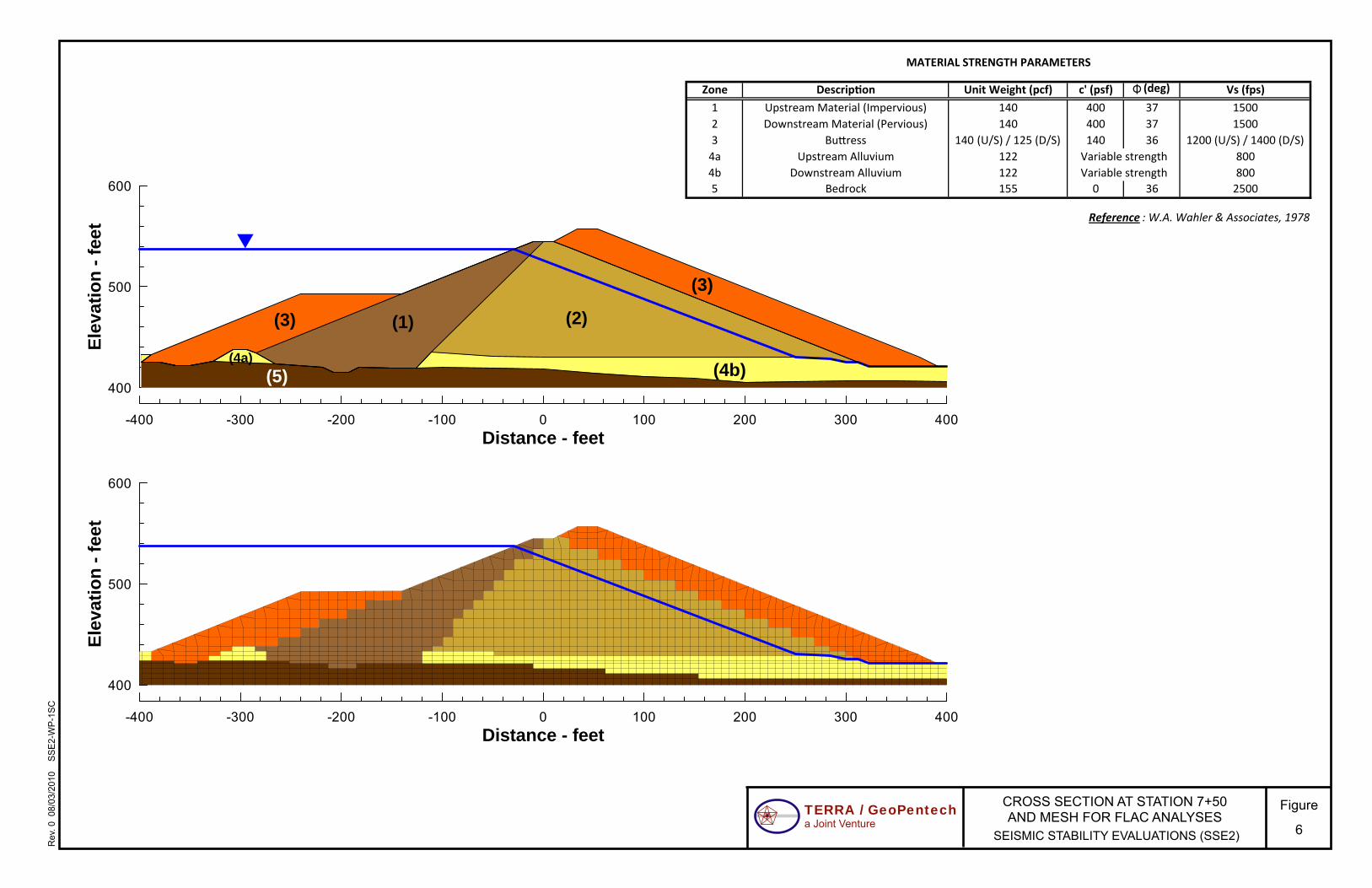
7.0 RESULTS OF PRELIMINARY ENGINEERING ANALYSES
Figure 6 shows the analysis cross section at Station 7+50 (the maximum height section) and the finite-difference mesh used in the preliminary FLAC seismic deformation analyses. The shear strength and stiffness parameters used for the various material types encountered in the analysis section are also shown on Figure 6. These parameter values are based on those used previously by Wahler (1978) except for the residual shear strength of the alluvium, which was taken as variable for the preliminary analyses.
We performed two sets of seismic deformation analyses using the input motion shown on Figure 3:
1. Assigning a very low residual shear strength for the upstream layer of alluvium (Su/’v=0.01).
2. Assigning a range of residual shear strength for the downstream layer of alluvium (Su/’v ranging between 0.15 and 0.7).
The upper portion of Figure 7 shows the seismic displacement contours in the upstream buttress at the end of the shaking. The time history of the displacement of the upstream buttress shown on the lower portion of Figure 7 shows that it comes to equilibrium even assuming an extremely low residual strength of the alluvium below the upstream buttress. As can be seen on Figure 7, the large but stabilized seismic displacements in the upstream zone of the dam are isolated and remain within the upstream buttress, allowing the rest of the dam embankment to be unaffected

WORK PLAN FOR SITE INVESTIGATIONS AND LABORATORY TESTING AT STEVENS CREEK DAM
SSE2-WP-1SC Final.docx 9
by large seismic displacements in the upstream zone. Therefore, even if the residual shear strength of the upstream alluvium layer is negligible (a low enough number that can be "confirmed" without further investigation), large seismic displacements would be localized to the upstream buttress area, and not affect the existing dam itself. This indicates that the upstream buttress would likely perform as intended even if the residual strength of the alluvium layer is negligible, and thus, that there is no need to perform any site investigation work for the alluvium in this area.
The upper portion of Figure 8 shows the seismic displacement contours in the main portion of the embankment at the end of the shaking when the downstream alluvium shear strength is assigned a value of Su/’v=0.4. This value was selected for discussion purposes and is not intended to represent the expected strength which has yet to be determined. The lower portion of Figure 8 shows the horizontal and vertical displacements of the downstream crest of the dam as a function of normalized residual strength of the alluvium; the seismic displacement contours shown on the upper portion of Figure 8 correspond to one data point on each of these curves. As can be seen from the curves shown on Figure 8, the end-of-the-shaking seismic displacement of the embankment is highly dependent on the residual shear strength assigned to the downstream alluvium. Therefore, determining the residual shear strength of the downstream alluvium is quite important for the seismic performance evaluation of the dam. This means an investigation focusing on the downstream alluvium is necessary to provide the appropriate residual shear strength characterization for this layer as input to the final FLAC analyses of the potential deformations of the dam.
Other strength and stiffness parameters to be used in the final analyses will be confirmed or modified from those shown in Figure 6 as appropriate based on the data developed from the investigation/testing and laboratory testing recommended in Section 8.0 and described further in Sections 9.0 to 14.0 of this work plan. If the downstream seismic deformations are found to be acceptable as evaluated by the final FLAC analyses, no mitigation would be required. However, if these deformations were found to be too large to be acceptable, some level of mitigation may be required.
8.0 PROPOSED EXPLORATION, TESTING AND INSTRUMENTATION
In order to develop a better understanding of the condition of the dam for our final seismic stability evaluation of the dam, we recommend that the supplemental subsurface investigations include sonic borings, rotary wash borings, downhole OYO geophysical suspension logging, and installation of piezometers at four locations on the dam, and one location downstream of the toe of the dam. These locations have been strategically selected to provide the information needed to fill data gaps related to the key geotechnical issues discussed in Section 3.0. We considered the use of test pits but concluded that previous test pits and trenches completed by Wahler were adequate, and that the boring program described herein will provide the data needed for the seismic stability evaluation. Penetration tests using the Becker Hammer (BPT) may also be performed if needed to adequately characterize the alluvial materials. The locations of the proposed explorations are shown on Figures 9 and 10. The basis for the selected boring locations, and the overall scope of the drilling, sampling and testing, are discussed further below. Details on field personnel and specialty contractors; procedures for drilling, sampling, and field

WORK PLAN FOR SITE INVESTIGATIONS AND LABORATORY TESTING AT STEVENS CREEK DAM
SSE2-WP-1SC Final.docx 10
testing; procedures for installation of piezometers; and laboratory testing are provided in Sections 9.0, 10.0, 11.0 and 12.0, respectively.
The results of our geologic modeling and preliminary seismic deformation analyses indicate that the sections of the embankment that are potentially susceptible to greater amounts of earthquake-induced deformation are in areas that are downstream of the cutoff, where thicker alluvial deposits are known to underlie the embankment. The most critical area appears to be along the maximum section over the former stream channel where younger alluvial deposits up to possibly 20 feet or more in thickness underlie the portion of the dam downstream of the cutoff. As discussed in Section 3.0, the potential for liquefaction of these alluvial materials has not been well-evaluated by the previously completed site investigations and the location of the piezometric surface within the dam foundation in this area (which affects the degree of saturation within the alluvium and the initial effective stresses in the alluvium and embankment) is not well defined. Consequently, we propose to explore the dam embankment and alluvial channel foundation conditions from three locations on the dam at the maximum section (Station 7+50) and at one location downstream of the toe of the dam, as shown on Figure 9. Pairs of borings will be advanced at each location: one by sonic drilling (designated by the postscript S) and one by mud rotary drilling (designated by the postscript MR). The two boreholes will be drilled 10 feet apart.
Boring pair SC-101 S/MR is located on the new raised dam crest. Boring pairs SC-102 S/MR and SC-103 S/MR are located on the downstream slope at Elevation 525 feet, and Elevation 485 feet, respectively. Boring pair SC-104 S/MR is located near the downstream toe of the dam, as shown on Figure 9. These locations have been selected in order to explore the foundation in anticipated areas of thicker alluvium and, in the case of the crest boring, the alluvium where it underlies the maximum thickness of embankment, and in the case of the toe boring, the alluvium downstream of the toe where it has little or no cover. These borings will also allow obtaining samples of the new downstream buttress, which has not previously been characterized for strength and index properties beyond the information contained in field density tests by Wahler (1986b).
The downstream slope borings will require the construction of a temporary access road. The proposed access road for these borings is shown on Figure 9 and design details are shown on Figure 11. The temporary access road will be constructed using 1-inch maximum size well graded angular gravel that will be spread using a bull dozer to achieve the geometry shown on Figure 11 to provide a wedge of fill material that requires no excavation of the existing dam. No compaction of the stone fill, other than that achieved by the spreading operation, will be required to make this temporary road suitable for access by the drilling equipment. The surface of the temporary access road will be leveled and, if necessary, smoothed by placing a 3-inch thick layer of aggregate base to provide a stable surface layer.
We also propose that boring pair SC-105 S/MR be located at Station 4+00, on the new raised crest approximately 100 feet right of the hinge point of the bend in the dam crest. These borings will provide additional information on the thickness and nature of the older alluvium beneath the embankment, the piezometric levels within these soils, and the composition and strength of the embankment materials.

WORK PLAN FOR SITE INVESTIGATIONS AND LABORATORY TESTING AT STEVENS CREEK DAM
SSE2-WP-1SC Final.docx 11
As indicated above, the “S” borings at each location will be made using a sonic drill rig. These borings should provide near-continuous recovery of the embankment and foundation materials and will be advanced a minimum of 5 feet into the Santa Clara Formation underlying the alluvium. Laboratory testing of samples from each of the borings will be made to determine physical and index properties that will provide data for soil classification and liquefaction potential analyses. These tests will also be used to target soil layers for sampling and field testing in companion mud rotary borings adjacent to each sonic boring location as described below. Details of the sonic drilling and sampling procedures are presented in Section 10.0.
A Casagrande piezometer, with the porous tip set approximately at the top of rock/bottom of alluvium interface, will be installed upon completion of each of the sonic boreholes. The sonic borings are drilled without using drilling fluid and produce a completely cased hole upon completion. Consequently, they are well-suited for installation of hydraulic piezometers in the alluvium. Details of the installation procedures for piezometers are described in Section 11.0. The Casagrande piezometers will be used to monitor piezometric levels within the alluvium. In addition, if appropriate based on the actual gradation of the alluvium, we will conduct falling head field permeability tests at these piezometers to provide data on the field permeability of these soils at the piezometer tip.
Upon completion of the laboratory physical and index properties testing on samples from the sonic borings, we will determine appropriate drilling and sampling procedures to be utilized for mud rotary (MR) borings that will be drilled adjacent to the sonic holes but offset a minimum of 10 feet to avoid interference between one borehole and the other. We expect that the mud rotary borings will be started approximately five weeks after completion of the sonic borings in order to allow sufficient time for review and interpretation of the results of the sonic borings and development of a sampling plan for the mud rotary borings. These mud rotary borings will be sampled using SPT and/or Modified California drive sampling methods, and using 3- or 4-inch diameter Pitcher Barrel sampling, as appropriate for the material type and gradation.
Down-hole shear wave velocity measurements will be performed using OYO down-hole suspension logging in three of the mud rotary borings: SC-101MR, SC-103MR and SC-104MR. Shear wave velocity measurements will be generally be made at 0.5-meter intervals throughout the depth of the borehole. The testing interval will be reduced to 0.25-meter within the zone of alluvial soils to better define the variability of shear wave velocity with depth. The mud rotary borings used for geophysical logging will extend a minimum of 15 feet into rock in order to allow the down-hole geophysical suspension logging equipment to measure shear wave velocity for the full depth of the foundation soils. The depth of drilling into rock will be increased to 40 feet at borings SC-101 MR and SC-104 MR so that shear wave velocity measurements can be made to a depth of 25 feet into rock in order to facilitate an estimate of the VS30 to be used in the review and selection of ground motions for the final seismic deformation analyses of the dam.
The down-hole shear wave velocity measurements may provide valuable data for estimating residual shear strength of the foundation soils, and will certainly provide valuable data for estimating stiffness of these soils. Given the dominant importance of the residual shear strength and stiffness of the foundation soils in the seismic stability evaluation, and given the general difficulty in estimating residual shear strength of gravelly soils, the importance of obtaining

WORK PLAN FOR SITE INVESTIGATIONS AND LABORATORY TESTING AT STEVENS CREEK DAM
SSE2-WP-1SC Final.docx 12
high-quality OYO data, and to interpret the data in an appropriate way, cannot be over-emphasized.
We propose to install three additional piezometers within the embankment at the location of Boring SC-102 MR to measure the variation of total head with depth that will supplement the data from the nearby existing piezometers installed in the embankment. These will be vibrating wire piezometers and will be installed by grouting the piezometers into place following the procedures contained in Section 11.0. Three piezometer sensors are planned at depths of 40, 60 and 80 feet as shown on Figure 10. We also propose to install two additional vibrating wire piezometers each in borings SC-101 MR and SC-103 MR. As shown in Figure 10, these piezometer sensors will be located near the top of the alluvium and at a depth of 20 feet below the top of the Santa Clara Formation.
9.0 FIELD PERSONNEL AND SPECIALTY CONTRACTORS
Richard Harlan, PG, CEG, the Geology Task Leader for the project, has over 25 years of experience related to dam investigations and studies. He has had a lead role in:
1. assembling and reviewing the information on Stevens Creek Dam that was available in District files and in the files of DSOD;
2. preparing the geologic base maps showing the distribution and thickness of soils left in place beneath the dam,
3. reviewing air photos,
4. geologic mapping of the materials at the dam site, and
5. preparing this work plan.
Mr. Harlan will be in the field full time during the field investigation program and will be responsible for the field supervision and logging of all the field exploration work. We have planned the work to be accomplished using one drill rig at a time so that Mr. Harlan can personally observe all the drilling, sampling, field testing and instrumentation installation; log all the borings; and prepare installation summaries for all piezometers. We believe this approach will ensure the quality and consistency of the work and avoid many of the problems associated with field investigations that require the use of multiple rigs and multiple field personnel.
The sonic drilling will be done by Boart Longyear, a worldwide drilling company that has strong capabilities in sonic drilling. Boart Longyear acquired Prosonic Corporation that completed the sonic drilling for the District as part of the Dam Instrumentation Program. We understand that the District was pleased with the quality of the sonic drilling on that project.
The mud rotary drilling and sampling will be done by Pitcher Drilling. Pitcher Drilling invented the Pitcher sampler and is widely recognized as one of the most qualified and experienced geotechnical drilling contractors in California. Pitcher Drilling completed the geotechnical drilling for TGP on San Pablo Dam and has worked on a number of other dam site investigations including Turner Dam, Chabot Dam, Calaveras Dam, and Folsom Dam.

WORK PLAN FOR SITE INVESTIGATIONS AND LABORATORY TESTING AT STEVENS CREEK DAM
SSE2-WP-1SC Final.docx 13
The downhole geophysical OYO logging will be completed by GeoVision. GeoVision has completed geophysical logging at 30 dams over the past decade, including geophysical logging at four of the District’s dams.
ENGEO will perform the geotechnical laboratory testing. ENGEO is a full-service earth science consulting firm that maintains three Northern California soil and materials testing laboratories managed by registered civil engineers: in San Ramon, Rocklin, and Manteca. ENGEO’s laboratories are Caltrans-certified, hold current verification status with the US Army Corps of Engineers, and are accredited through the National Institute of Standards and Technology (NIST) by participating in the Cement and Concrete Reference Laboratory (CCRL) and in the AASHTO Materials Reference Laboratories (AMRL) proficiency sample and laboratory inspection programs.
10.0 PROCEDURES FOR GEOTECHNICAL DRILLING AND SAMPLING
The sonic borings will be drilled using a Boart Longyear Model 600 C Full Sonic Track rig. This rig weights 37,700 lbs and has nominal dimensions of 33 ft x 8.5 ft x 11.3 ft (length x width x height) in highway travel mode and 30 ft x 11.5 ft x 35 ft (length x width x height) when drilling. The borehole will be 6 inches in diameter and 4-inch diameter continuous core samples will be obtained. The cores will be visually examined, classified and logged using the Unified Soil Classification System. They will then be photographed and stored in core boxes. The core samples will be delivered to the geotechnical laboratory within 48 hours of sampling. The sonic boring will extend a minimum of 5 feet into rock. A Casagrande hydraulic piezometer will be installed upon completion of the borehole with the bottom of the piezometer tip located at the elevation of the interface between the alluvium and the bedrock, as discussed in Section 11.0.
The mud-rotary borings will be drilled using a Fraste Model MD/XL drill rig that has dimensions of 30 ft x 8 ft x 11 ft (length x width x height) for highway travel and weighs 28,660 lbs. The boreholes will be approximately 6 inches in diameter and will be advanced using a tri-cone bit with side discharge. In general, a 3-inch diameter Pitcher barrel sampler and a driven modified California sampler (3-in OD) will be alternated to obtain samples every 5 feet in the embankment sections. A 4-inch diameter Pitcher barrel sampler will be available and may be used to obtain relatively undisturbed samples in gravelly soils. An SPT split spoon will be used at the discretion of the field geologist if cohesionless soils are encountered in the embankment.
The drilling fluid pressure will be constantly monitored to minimize the risk of hydrofracturing in the dam. We will monitor the fluid pressure with an approved gauge to ensure that the drilling fluid pressure does not exceed 0.45 psi per foot of boring depth. We will also minimize the drilling fluid pressure by keeping the fluid relatively clean and by maintaining appropriate drilling rates. All fluid losses will be monitored and recorded. If we suspect that hydrofracturing may be occurring, we will suspend drilling and notify the District immediately. When the bottom of the embankment material is encountered, continuous sampling will be performed until bedrock is encountered. The borings will generally be advanced 5 feet into rock but the borings at the crest of the dam will advanced a minimum of 15 feet into rock to allow the sensors on the down-hole geophysical logging tool to measure shear wave velocity at the top of rock. The penetration into rock will be increased to 40 feet at Boring SC-102 MR in order to obtain

WORK PLAN FOR SITE INVESTIGATIONS AND LABORATORY TESTING AT STEVENS CREEK DAM
SSE2-WP-1SC Final.docx 14
measurements of shear wave velocity to a depth of 25 feet below the top of rock. The rock sections of the borings will be logged based on cuttings, drill action, drill fluid return, rate of drilling, and any other pertinent fugitive data which will be noted accordingly on the boring logs; coring of the bedrock is not necessary and will not be performed.
The sampling in the alluvium and colluvium will consist primarily of SPT sampling so that blow counts can be obtained. An automatic trip hammer will be used to drive the SPT sampler. Hammer energy measurements will be taken for each hammer during the course of the project but our intent is to use the same hammer for all borings at Stevens Creek Dam so that hammer energy measurements will only be required once. SPT blow counts will be recorded in term of blows per inch so that the presence of gravels can be assessed for proper blow count correction. Upon completion of drilling and sampling, the borings will be grouted with cement bentonite grout. We propose to use the grout mix currently being used on the SSE1 project that consists of the following quantities mixed in order:
1. 30 gallons of water
2. 25 pounds of bentonite powder
3. 94 pounds of cement
The minimum mixing time for the grout mix is 5 to 7 minutes. If needed, the proportions of the grout mix may be modified. Three vibrating wire piezometers will be installed in Boring SC-104 MR upon completion of the boring using the grouted-in piezometer installation procedure described in Section 11.2.
If the gravel content in the foundation soils is found to be greater than 30 percent based on the results of laboratory tests made on samples from the sonic borings, and depending on the maximum grain size of the gravel particles encountered, the need for BPT will be evaluated to supplement the evaluation of liquefaction potential of the gravelly materials. It should be noted, however, that gravel content greater than 30 percent may be acceptable depending on the maximum size of gravel particles. If recommended, BPT soundings will be advanced using a 180lb ICE-180 hammer with supercharger and 6.6-inch plugged bit.
Cuttings and drilling fluid will be collected and placed in drums or a central tank at the site. We will coordinate the disposal of the cuttings and drilling fluid; however, it is noted that the District will be required to sign the disposal manifests and provide justification for assuming that the materials do not contain constituents of concern.
11.0 PROCEDURES FOR PIEZOMETER INSTALLATION
11.1 Casagrande Piezometers The Casagrande piezometer installed in each sonic boring will consist of a 12-inch polyethylene tip connected to a ¾-inch diameter Schedule 80 PVC riser pipe. The 5-foot long portion of the borehole drilled into rock will be backfilled with a predetermined volume of bentonite chips, so that the bentonite chips fill the borehole in rock but do not extend above the top of rock. The piezometer sand collection zone will extend from the top of rock to 2.5 feet above the interface

WORK PLAN FOR SITE INVESTIGATIONS AND LABORATORY TESTING AT STEVENS CREEK DAM
SSE2-WP-1SC Final.docx 15
between the alluvium and bedrock. The installation procedure for the Casagrande piezometers is as follows:
1. The bentonite chips will be allowed to hydrate before installation of the Casagrande piezometer begins.
2. A cylindrical weight will be lowered down the hole to verify that the hole is free of obstructions and to check the depth of the top of bentonite chip zone.
3. Clean sand will be placed below the bottom elevation of the piezometer tip (i.e., six inches above the elevation of the top of the Santa Clara Formation) and tamped in place. The casing will be pulled as the sand backfilling proceeds such that the bottom of the casing is always 6 to 12 inches below the top of the sand backfill.
4. The assembled piezometer will be lowered into the hole, clean sand backfill placed around the piezometer, and the casing pulled in six-inch increments. The process will continue until the level of the sand backfill is 12 inches above the top of the piezometer tip. The sand backfill will be tamped in place prior to placement of the bentonite seal.
5. The casing will be lifted in six-inch increments and the hole will be backfilled with bentonite pellets until a two-foot seal has been formed. Bentonite pellets will be slowly dropped in a single file down the hole to avoid bridging of the pellets in the casing or the borehole. The thickness of the bentonite seal will be verified using the tamping hammer.
6. Upon completion of the bentonite seal, the borehole will be tremie-backfilled with cement-bentonite grout as the casing is being withdrawn.
The casing will not be rotated during removal. Once the casing is removed, the borehole will be topped off with grout and a locking instrument cover will be installed. The grout used to backfilled the hole will be that same as that currently being used on the SSE1 project, as discussed in Section 10.0.
11.2 Vibrating Wire Piezometers
Upon completion of borings SC-101 MR, SC-102 MR and SC-103 MR, vibrating wire piezometers will be installed and grouted in the borehole in accordance with the procedure recommended by the manufacturer of the piezometers for installation in medium to hard soils and as follows:
1. The borehole will be tremie grouted to about two feet below the elevation where the deepest piezometer is to be installed.
2. The vibrating wire piezometers will be attached (with the filter tip up) to a 1 ¼-inch schedule 80 PVC pipe with slip couplings and the cables from the piezometers will be routed to the ground surface inside the PVC pipe. The cable from each piezometer will be brought from the outside of the PVC pipe to the inside of the pipe through a slot cut in the pipe below the location of the sensor. The slot will be wide enough and long enough so that the piezometer cable can be folded back into the pipe without kinking. The top of the slot will be located 6 inches below the bottom of the inverted piezometer assembly.

WORK PLAN FOR SITE INVESTIGATIONS AND LABORATORY TESTING AT STEVENS CREEK DAM
SSE2-WP-1SC Final.docx 16
3. Installation will begin with the deepest piezometer. The piezometer will be attached to the pipe using plastic tape covering only the lower half of the piezometer and its cable will be routed inside the pipe as described above. The penetration of the cable through the wall of the PVC pipe will also be covered with plastic tape to prevent escape of grout through the slot during grouting. The tape coverage will extend 3 inches below the bottom of the slot. The assembly will then be lowered into the borehole, adding lengths of pipe as required until the location of the second piezometer is reached. At that point, the second piezometer will be installed and the operation repeated until all the piezometers have been lowered into the borehole and the grout pipe extends above the ground surface to facilitate grouting. PVC cement will be used to assemble the pipe with slip couplings.
4. Once the PVC pipe is above the ground surface at the level desired for grouting, a threaded Y-type coupling will be secured to the top of the pipe. The piezometer cables will exit the pipe through the top of the Y while grout is being pumped into the other side. The annular space between the top of the Y and the piezometer cables will be plugged using rags and plastic tape to prevent leakage of grout. The annular space between the grout pipe and the borehole will be tremie grouted through the PVC pipe until grout appears at the top of the borehole. Grouting pressure will be kept as low as possible consistent with controlled, slow displacement of drilling mud from the borehole. The borehole casing will be withdrawn as the borehole is grouted. A locking instrument cover will be installed upon completion.
5. The grout mix will be the same as that used to grout the other borings, as discussed in Section 10.0.
12.0 LABORATORY TESTING
Samples will be transported to the laboratory within 48 hours of sampling along with preliminary laboratory testing assignments. The type and approximate number of laboratory tests planned for the samples obtained from the borings at Stevens Creek Dam are summarized below.
50 Moisture Content and Density 25 Sieve Analyses 25 Sieve and Hydrometer 25 Minus 200 Wash 35 Liquid Limit, Plastic Limit and Plasticity Index 4 Compaction Tests 6 Consolidated Undrained Triaxial Compression Tests with PP Measurements 2 Falling Head Permeability Tests 6 Pinhole Dispersion Tests
The final number of tests of each type will be adjusted to reflect the soil conditions actually encountered. Consequently, variations from the planned number of tests should be expected but the scope of the actual laboratory testing program will be controlled so that the cost of the actual laboratory testing will be approximately the same as the cost of the planned laboratory testing program.

WORK PLAN FOR SITE INVESTIGATIONS AND LABORATORY TESTING AT STEVENS CREEK DAM
SSE2-WP-1SC Final.docx 17
13.0 SCHEDULE
The project schedule shows sonic borings beginning in November 2010, mud-rotary borings beginning approximately five weeks after completion of the sonic borings, and a draft of the data report summarizing the field and laboratory data being completed by mid February, 2011. The actual amount of time in the field for both the sonic and mud-rotary drilling is expected to be a total of about 20 days. Drilling will generally take place Monday through Friday between about 7:00 am and 5:00 pm, with the option to drill on Saturday if the schedule requires it.
14.0 ENVIRONMENTAL CONSIDERATIONS
The work will be performed on the crest of the dam, the downstream face of the dam, and the access road at the foot of the dam and none of the exploration locations is in environmentally sensitive areas. Consequently, there are no special environmental considerations for this project. Nevertheless, the field crews will receive a briefing by environmental specialists from the District at the start of field work to make field personnel aware of general environmental requirements and to delineate and discuss environmentally sensitive areas and species in the vicinity of the work area.
15.0 REFERENCES
AMEC, 2009 (January), Technical Memorandum No. 3, Seismotectonic and Ground Motion Study, Seismic Stability Evaluation of DIP Phase 1 Dams.
Brabb, E.E. et al, 2000, Geologic Map and Map Database of the Palo Alto 30x60 Quadrangle, USGS MF-2332.
DSOD - California Department of Water Resources, 1935-1936, Inspection Memoranda by G.F. Engle on Construction of Stevens Creek Dam (on file at DSOD).
DSOD - California Department of Water Resources – Division of Safety of Dams, 1985-1986, Inspection of Dam Construction Reports for Stevens Creek Dam Modifications, with Memoranda of Geologic Inspection (on file at DSOD).
DSOD - California Department of Water Resources – Division of Safety of Dams, 2010 (June), DSOD Comments on DM-2 and Interim DM-4, Guadalupe, Almaden, and Calero Dams, dated June 10, 2010.
Santa Clara Valley Water Conservation District, 1934, Contracts, Proposals, Specifications, Maps – Contract No. 3 for Construction of Stevens Creek Dam and Spillway.
Santa Clara Valley Water District, 1976, Stevens Creek Reservoir Landslide Investigation.
Santa Clara Valley Water District, 1985, Specifications and Contract Documents for the Stevens Creek Dam Modifications.
Santa Clara Valley Water District, 2005, Special Seepage Investigation, Stevens Creek Dam.

WORK PLAN FOR SITE INVESTIGATIONS AND LABORATORY TESTING AT STEVENS CREEK DAM
SSE2-WP-1SC Final.docx 18
Santa Clara Valley Water District, 2010a (January), Foundation Analysis Report on Chesbro No.72-11, Lenihan No.72-8, Stevens Creek No. 72-7, and Uvas No. 72-12 Dams (SSE-2 Dams), prepared by James L. Nelson.
Santa Clara Valley Water District, 2010b (April), 2010 Surveillance Report, March 2009 through March 2010, Stevens Creek Dam No.72-7.
Santa Clara Valley Water District, 2010c (June), Black and white aerial photo sets (1969, 1983, 1985(2), 1986, and 2002), on-file at SCVWD (see Table 2).
Santa Clara Valley Water District, 2010d (June), As-constructed foundation topography beneath Stevens Creek Dam, GIS data shape file.
Santa Clara Valley Water District, 2010e (June), Original pre-construction topography beneath Stevens Creek Dam GIS data shape file.
Shannon & Wilson, Inc., 1976 (December), Piezometer Installation, Stevens Creek Dam.
Sorg and McLaughlin, 1975, Geologic Map of the Sargent-Berrocal Fault Zone between Los Gatos and Los Altos Hills.
Tolman, C.F., 1934 (October), Geology of the Murphy Dam site on Stevens Creek.
W.A. Wahler and Associates, 1978 (December), Seismic Safety Evaluation, Stevens Creek Dam.
Wahler Associates, 1982 (October), Report on Preliminary Remedial Design Investigation of Stevens Creek Dam.
Wahler Associates, 1984 (August), Remedial Design Report, Stevens Creek Dam.
Wahler Associates, 1986a, As-Built Drawings, Stevens Creek Dam Modifications (on file at SCVWD).
Wahler Associates, 1986b, Summary of Field Density Tests, Stevens Creek Dam Modifications (on file at DSOD).
Woodward-Clyde Consultants, 1976a (January), Part 1 - Geology and Seismicity - Seismic Stability Assessment of Four Dams, Santa Clara Valley Water District.
Woodward-Clyde Consultants, 1976b (June), Part II – Field Investigations and Engineering Analyses - Seismic Stability Assessment of Four Dams, Santa Clara Valley Water District.

SSE2-WP-1SC Final.docx x
TABLE 1 AERIAL PHOTOGRAPHS
Photo Type Date Scale Source
Black and White Stereo 11/4/1969 ~1:12,000 SCVWD
Black and White Stereo 3/31/1983 ~1:16,000 SCVWD
Black and White Stereo 6/19/1985 1:4,800 SCVWD
Black and White Stereo 11/20/1985 1:4,800 SCVWD
Black and White Stereo 1/10/1986 1:4,800 SCVWD
Black and White Stereo 11/5/2002 1:12,000 SCVWD

SSE2-WP-1SC Final.docx x
TABLE 2 DAM FOUNDATION ELEVATION DATA
Boring1 Elevation (Feet) Inferred Thickness
of Alluvium (Feet) Dam Foundation Top of Santa Clara
Formation
WCC-1 485 474 11
WCC-2 485 475 10
WCC-3 471 471 0
WCC-4 434 430 4
WCC-5 432 417 15
WCC-6 434 430 4
S&W B-1 431 421 or lower? 10+
S&W B-2 N.E.2 (below 448) below 448 ?
S&W B-3 N.E. (below 433.5) below 433.5 ?
WA SC-1 522.2 510 12.2
WA SC-2 N.E. (below 440) below 440 ?
WA T-1 N.E. (below 436) below 436 ?
WA T-2 463 452.5 10.5
WA T-3 502 below 493 9+
WA T-4 431 below 421 10+
WA SC-3 N.E. (below 428) below 428 ?
WA SC-4 427 below 418 9+
WA SC-5 431 below 428.5 2.5+
WA SC-6 427 below 423 4+
WA SC-7 429 below 425.5 3.5+
WA SC-8 439 below 426 13+
WA SC-9 433.5 below 432.5 1+
WA SC-10 436 423 13
WA SC-11 435 428 7
WA SC-12 436 below 430 6+
1 WCC - Woodward Clyde Consultants borings, 1975.
S&W - Shannon & Wilson, Inc. borings, 1976. WA - Wahler Associates borings and trenches, 1978 – 1984 (T- indicates trench); Wahler elevation data corrected to reflect currently accepted nominal original dam crest elevation of 545 feet. Wahler boring designations “DH-“ removed to simplify naming convention.
2 N.E. = Not Encountered.

6,102,400 6,102,500 6,102,600 6,102,700 6,102,800 6,102,900 6,103,000 6,103,100 6,103,200 6,103,300 6,103,400 6,103,500 6,103,600 6,103,7001,934,700
1,934,800
1,934,900
1,935,000
1,935,100
1,935,200
1,935,300
1,935,400
1,935,500
INLET STRUCTURE
CENTERLINE OUTLET CONDUIT
OUTLET STRUCTURE
EASTING, FEET
NO
RT
HIN
G, F
EE
T
ORIGINAL TOE
ORIGINAL TOE
BUTTRESS TOE
BUTTRESS TOE
NEW CREST
ORIGINAL CREST
LEGENDN
Note:Wahler borings at inlet structure not shown
2+00
3+00
4+00
5+00
6+007+00
8+009+00
10+0011+00
Existing Piezometer
B-6
B-9
B-8
B-7
B-1 & B-2
WA SC-11
WA SC-10
WA SC-6WCC-3
WCC-1
WCC-2
WCC-6
WCC-4
WCC-5
WA SC-7
WA SC-8
WA SC-9
WA SC-12
WA SC-5 WA SC-4
S&W B-1
WA T-3
WA T-4
WA SC-1
WA T-2
TRENCH LOCATED 50 FEET NORTH OF LOCATION SHOWN
Existing Boring into Santa Clara Formation
Existing Boring Terminated above Santa Clara Formation
Existing Boring Terminated in Embankment
B-3, B-4, & B-5
S&W B-2
WA SC-2
WA SC-3
WA T-1
S&W B-3
Figure
1
FOOTPRINT OF STEVENS CREEK DAM AND PLAN OF PREVIOUS EXPLORATIONS
TERRA / GeoPentecha Joint Venture
SEISMIC STABILITY EVALUATIONS (SSE2)
Rev
. 2 0
8/25
/201
0
SS
E2-
WP
-1S
C

UPSTREAM BUTTRESS
560
540
520
500
480
460
440
420
400
560
540
520
500
480
460
440
420
400
EMBANKMENT(IMPERVIOUS)
EMBANKMENT(PERVIOUS)
FILTER/DRAIN DOWNSTREAM BUTTRESS
DOWNSTREAM BUTTRESS CREST APPROX. ELEV. 557 FEET
ORIGINAL DAM CREST APPROX. ELEV. 545 FEET
SPILLWAY CREST ELEV. 537.5 FEET
CUT-OFF TRENCH
ALLUVIUM (TYP.)
ELE
VA
TIO
N, F
EE
T
B-6
STATION 9+70
SANTA CLARA FORMATION
2.51
2.51
2.51
UPSTREAM BUTTRESS
EMBANKMENT(IMPERVIOUS)
SANTA CLARA FORMATION
EMBANKMENT(PERVIOUS)
FILTER/DRAINDOWNSTREAM
BUTTRESS
RIPRAP AT TOE OF DAM
DOWNSTREAM BUTTRESS CREST APPROX. ELEV. 557 FEET
ORIGINAL DAM CREST APPROX. ELEV. 545 FEET
SPILLWAY CREST ELEV. 537.5 FEET
CUT-OFF TRENCH ALLUVIUM (TYP.)
STATION 7+50
560
540
520
500
480
460
440
420
400
560
540
520
500
480
460
440
420
400
ELE
VA
TIO
N, F
EE
T
B-5
B-9
B-8
B-7
B-4
B-3
B-2
B-1
APPROXIMATE SCALE IN FEET
30 0 30 60
2.51
2.51
2.51
WCC-2WCC-1
WCC-3
S&W B-1
WCC-5
WCC-4
WCC-6
WA SC-11 & WA SC-10
B-4Sensor Location
Number of Existing Piezometer
Piezometric Elevation at Sensor1
WCC-4
Existing Boring Number
Length of Existing Deep Boring
LEGEND
Notes:1. Piezometric Elevations from Figure 3 of 2010 Surveillance Report.2. Elevations of top of Santa Clara Formation and base of dam embankment and buttresses from geologic model developed by TGP.3. Top flow line (phreatic surface) estimated and approximates that used by Wahler Associates (1984)
??
TERRA / GeoPentecha Joint Venture
SEISMIC STABILITY EVALUATIONS (SSE2)
Figure
2
CROSS SECTIONSSTEVENS CREEK DAM
Rev
. 2
09/0
9/20
10
SS
E2-
WP
-1S
C

FAULT NORMAL
0.01 0.1 1 10Period - sec
0
0.5
1
1.5
2
2.5
3
Sp
ectr
alA
ccel
erat
ion
-g
FaultNormal
TargetFaultNormal
0 10 20 30-1.5
-1
-0.5
0
0.5
1
1.5
Acc
eler
atio
n-
g
0 10 20 30-200
-100
0
100
200
Vel
oci
ty-
cm/s
0 10 20 30Time - sec
-150
-100
-50
0
50
100
150
Dis
pla
cem
ent
-cm
0111.010.0
Period - sec
0
0.5
1
1.5
2
2.5
3
Sp
ectr
alA
ccel
erat
ion
-g
Enveloppe
Stanford-Monte Vista
San Andreas
TERRA / GeoPentecha Joint Venture
SEISMIC STABILITY EVALUATIONS (SSE2)
Figure
3
DESIGN RESPONSE SPECTRUMAND MATCHED TIME HISTORIES
Rev
. 0 0
8/03
/201
0
SS
E2-
WP
-1S
C

6,102,400 6,102,500 6,102,600 6,102,700 6,102,800 6,102,900 6,103,000 6,103,100 6,103,200 6,103,300 6,103,400 6,103,500 6,103,600 6,103,7001,934,700
1,934,800
1,934,900
1,935,000
1,935,100
1,935,200
1,935,300
1,935,400
1,935,500
0
5
10
15
20
25
30
35
EASTING, FEET
NO
RT
HIN
G, F
EE
T
ORIGINAL TOE
BUTTRESS TOE
BUTTRESS TOE
NEW CREST
ORIGINAL CREST
ESTIMATED THICKNESS OF SOILS LEFT IN PLACE, FEET
LEGEND
N
DOWNSTREAM
UPSTREAM
Note: Wahler borings at inlet structure not shown
2+00
3+00
4+00
5+00
6+007+00
8+009+00
10+0011+00
B-6
B-9
B-8
B-7
B-1 & B-2
Existing Piezometer
WA SC-11
WA SC-10
WA SC-6WCC-3
WCC-1
WCC-2
WCC-6
WCC-4
WCC-5
WA SC-7
WA SC-8
WA SC-9
WA SC-12
WA SC-5 WA SC-4
S&W B-1
WA T-3
WA T-4
WA SC-1
WA T-2
TRENCH LOCATED 50 FEET NORTH OF LOCATION SHOWN
B-3, B-4, & B-5
Existing Boring into Santa Clara Formation
Existing Boring Terminated above Santa Clara Formation
S&W B-2
WA SC-2
WA SC-3
WA T-1
S&W B-3
Existing Boring Terminated in Embankment
TERRA / GeoPentecha Joint Venture
SEISMIC STABILITY EVALUATIONS (SSE2)
Figure
4
ESTIMATED THICKNESS OF SOILS LEFT IN PLACE - STEVENS CREEK DAM
Rev
. 3
08/2
6/20
10
SS
E2-
WP
-1S
C

6,102,00 6,102,100 6,102,200 6,102,300 6,102,400 6,102,500 6,102,600 6,102,700 6,102,800 6,102,900 6,103,000 6,103,100 6,103,200 6,103,300 6,103,400 6,103,500 6,103,600 6,103,700 6,103,800
1,934,700
1,934,800
1,934,600
1,934,900
1,935,000
1,935,100
1,935,200
1,935,300
1,935,400
1,935,500
1,935,600
1,935,700
1,935,800
625
615
610
600
585
595
630
565
635
560
650
540
530
525
520
515
615
580
535
590
630
595 545
550
610
555
605 535
570
565
555
585
540
600 560
62535
620
545
535 530525 520
515
595
600
605
0
610
615
585
620
580
575
630
570635
560
510505
645
675
50069070
0
540
495
480 475485470
490
465460
455
450 445
440
435
550
430
4
555
550
455
495
480
430
575 5
555
540
490
510
545
500
435
490
615
445
450
450
445
535
465
520
625
535
525510
460
545
455
570
470
610
540
520
585
565
560
460
600
530
585
555
545
590
550
520
545
450
440
610
515
615
60
555
580
560
530
??
??
??
?
?
?
?
?
?
?
?
?
??
Qya
Qya
QTsc
QTsc
Qc/QTsc?
QTscQTsc?
QTsc
QTsc Qoa
Qoa?
Qc (overQoa)?
Qc (overQoa)
Qc (over QTsc)
Fill (overQya)
Qya
Qoa?Fill
Fill
QTsc QTsc
QTsc
Qoa
QTs
c
Qc (overQoa)
QTs
c
Qc
(ove
rQTs
c)
Qc/QTs
c?
Qoa
Qoa
Fill
Fill
Qc (overQTsc or Qoa)
Qc and/or Fill (
over Qoa or
QTsc)
Fill (overQya)
Toe Drain
Fill Qoa
base Qoa as per Vantine (1972)
Qc/
QTs
c/Q
oa?Old sl
ide
(evid
ent on
1969 airphotos)
Old slide as p
er
Vantine (1
972)
now heavily
overg
rown
QTsc
QTsc
3530
35
Qya
Fill
Fill
EXPLANATIONNCONTOUR INTERVAL: (5’)
LOCATION OF MAPPED OUTCROP
STRIKE & DIP OF BEDDING
CONTACT, DASHED WHERE APPROXIMATE, DOTTED WHERE CONCELED, QUERIED WHERE UNCERTAIN
LANDSLIDE
DAM OUTLINE
FILL Over Qya
Fill or Qc - Over Qoa
Fill or Qc - Over Qtsc
Qya YOUNG ALLUVIUM
Qoa OLDER ALLUVIUM
QTsc SANTA CLARA FORMATION
35
?
NOTES:
1: LOCATION OF INLET/OUTLET STRUCTURE PROVIDED BY SCVWD
2: LIMITS OF UPSTREAM PORTION OF EMBANKMENT AS PER 1937 AS-BUILT PLAN, 1985 WAHLER MODIFICATIONS EMBANKMENT PLAN (NO 1986 AS-BUILT PLAN AVAILABLE), AND 1986 WAHLER AS-BUILT SECTIONS FOR UPSTREAM BUTRESS
3: GEOLOGY OF UNITS UNDERLYING EMBANKMENT ESTIMATED FROM 1937 AS-BUILT DRAWINGS, PREVIOUS EXPLORATION (1975-1984), WAHLER 1986 AS-BUILT SECTIONS OF UPSTREAM BUTRESS, AND DSOD CONSTRUCTION INSPECTION RECORDS FROM 1935-36 AND 1985-86.
Figure
5
GEOLOGIC MAPPINGSTEVENS CREEK DAM
TERRA / GeoPentecha Joint Venture
SEISMIC STABILITY EVALUATIONS (SSE2)
Rev
. 1 0
9/09
/201
0
SS
E2-
WP
-1S
C
-400 -300 -200 -100 0 100 200 300 400Distance - feet
400
500
600
Ele
vati
on
-fe
et
-400 -300 -200 -100 0 100 200 300 400Distance - feet
400
500
600
Ele
vati
on
-fe
et
(1) (2)(3)
(3)
(4b)(4a)
(5)
Zone Description Unit Weight (pcf) c' (psf) Φ (deg) Vs (fps)
1 Upstream Material (Impervious) 140 400 37 15002 Downstream Material (Pervious) 140 400 37 15003 Buttress 140 (U/S) / 125 (D/S) 140 36 1200 (U/S) / 1400 (D/S)
4a Upstream 008221muivullA4b Downstream 008221muivullA
0052630551kcordeB5
Reference : W.A. Wahler & Associates, 1978
Variable strengthVariable strength
MATERIAL STRENGTH PARAMETERS
TERRA / GeoPentecha Joint Venture
SEISMIC STABILITY EVALUATIONS (SSE2)
Figure
6
CROSS SECTION AT STATION 7+50AND MESH FOR FLAC ANALYSES
Rev
. 0 0
8/03
/201
0
SSE2
-WP-
1SC

-400 -300 -200 -100 0 100 200 300 400
Distance - feet
400
500
600
Ele
vati
on
-fe
et
9.7'
0.1'
6.4'
4.2'
Displacement Scale(feet)
UPSTREAM ALLUVIUMSu/ 'v=0.01
0 10 20 30 40
Time - sec
-8
-6
-4
-2
0
2B
erm
Cre
st(P
oin
t"A
")S
eism
icD
isp
lace
men
t-
ft
HorizontalDisplacement
VerticalSettlement
A
(6a)
(6b)
> 5.55.04.54.03.53.02.52.01.51.00.50.0
TERRA / GeoPentecha Joint Venture
SEISMIC STABILITY EVALUATIONS (SSE2)
Figure
7
UPSTREAM DISPLACEMENT CONTOURS AND BERM CREST DISPLACEMENT TIME HISTORY
Rev
. 0 0
8/03
/201
0
SS
E2-
WP
-1S
C

-400 -300 -200 -100 0 100 200 300 400Distance - feet
400
500
600
Ele
vati
on
-fe
et
4.5'
3.1'
4.4'
3.4'
9.0'1.3'
DOWNSTREAM ALLUVIUMSu/ 'v=0.4
Displacement Scale(feet)
0 0.2 0.4 0.6 0.8Downstream Alluvium Su/ 'v
0
4
8
12
16
20
Ho
rizo
nta
lDo
wn
stra
mS
eism
icD
isp
lace
men
to
fD
ow
nst
ream
Cre
st(P
oin
t"B
")-
ft
0 0.2 0.4 0.6 0.8Downstream Alluvium Su/ 'v
0
4
8
12
16
20
Ver
tica
lS
eism
icS
ettl
emen
to
fD
ow
nst
ream
Cre
st(P
oin
t"B
")-
ft
B
(7a)
(7b)
> 5.55.04.54.03.53.02.52.01.51.00.50.0
σσ
TERRA / GeoPentecha Joint Venture
SEISMIC STABILITY EVALUATIONS (SSE2)
Figure
8
DOWNSTREAM CREST DISPLACEMENTSVS SHEAR STRENGTH OF ALLUVIUM
Rev
. 0 0
8/03
/201
0
SSE2
-WP-
1SC

A
A
B
B
C
C 12-FT WIDE TEMPORARY ACCESS ROAD (3.6 : 1 SLOPE)
15-FT X 60-FT WORKING PLATFORM (LEVEL)
15-FT WIDE WORKING PLATFORM (LEVEL)
12-FT WIDE TEMPORARY ACCESS ROAD (3.2 : 1 SLOPE)
2+00
3+00
4+00
5+00
6+007+00
8+009+00
10+0011+00
SC-104 S/MR
SC-101 S/MR
SC-103 S/MR
SC-105 S/MR
SC-102 S/MR
Figure
9
FINAL SUBSURFACE EXPLORATION PLANSTEVENS CREEK DAM
TERRA / GeoPentecha Joint Venture
SEISMIC STABILITY EVALUATIONS (SSE2)
Rev
. 4
10/2
6/20
10
SS
E2-
WP
-1S
C
EXPLORATION LOCATION AND NUMBER
S = Sonic Boring
1 Casagrande Piezometer in Alluvium (All Locations)
Field Permability Test(All Casagrande Piezometers)
MR = Mud-Rotary Boring
Downhole Geophysical Logging(SC-101, SC-104, SC-105)
7 Vibrating Wire Piezometers (See Figure 10)
Sonic and Mud-Rotary Borings drilled 10 feet apart.
Note: See Figure 11 for sections and details of access road.
SC-102 S/MR

560
540
520
500
480
460
440
560
540
520
500
480
460
440
EMBANKMENT(IMPERVIOUS)
EMBANKMENT(PERVIOUS)
FILTER/DRAIN DOWNSTREAM BUTTRESS
SPILLWAY CREST ELEV. 537.5 FEET
CUT-OFF TRENCH
OLDER ALLUVIUM (TYP.)
ELE
VA
TIO
N, F
EE
T
STATION 4+00
SC-105 S/MR
SANTA CLARA FORMATION
))))
UPSTREAM BUTTRESS
EMBANKMENT(IMPERVIOUS)
EMBANKMENT(PERVIOUS)
FILTER/DRAIN
DOWNSTREAM BUTTRESS
RIPRAP AT TOE OF DAM
SPILLWAY CREST ELEV. 537.5 FEET
CUT-OFF TRENCH ALLUVIUM (TYP.)
STATION 7+50
560
540
520
500
480
460
440
420
400
560
540
520
500
480
460
440
420
400
ELE
VA
TIO
N, F
EE
T
B-5
B-9
B-8
B-7
B-4
B-3
B-2
B-1
APPROXIMATE SCALE IN FEET
30 0 30 60
SC-102 S/MR
SC-101 S/MR
SANTA CLARA FORMATION
SC-103 S/MR
SC-104 S/MR FILL
S&W B-1
WCC-5
WCC-4
WCC-6
WA SC-11 & WA SC-10
New Casagrande Piezometer
New Vibrating Wire Piezometer
Notes:1. Piezometric Elevations from Figure 3 of 2010 Surveillance Report.2. Elevations of top of Santa Clara Formation and base of dam embankment and buttresses from geologic model developed by TGP.3. Piezometer B-6 at station 9+70 is screened approximately 25 ft. below top of the Santa Clara Formation.
B-4Sensor Location
Number of Existing Piezometer
Piezometric Elevation at Sensor1
LEGEND
WCC-4
Existing Boring Number
SC-102 S/MR
New Boring Number
Length of Existing Deep Boring
Length of New Boring
TERRA / GeoPentecha Joint Venture
SEISMIC STABILITY EVALUATIONS (SSE2)
Figure
10
PROPOSED EXPLORATIONSSTEVENS CREEK DAM
Rev
. 4
10/2
6/20
10
SS
E2-
WP
-1S
C

SECTION C-C FROM FIGURE 9
EXISTING D/S BUTTRESS
STONE FILL FOR ACCESS ROAD
1.51
32 FT 26 FT
SILT FENCE
1 inch = 10 ft0 5 10
13.39
SECTION B-B FROM FIGURE 9
1.51
12.5
EXISTING D/S BUTTRESS
STONE FILL FOR ACCESS ROAD
15 FT 22.5 FT
SILT FENCE
1 inch = 10 ft0 5 10
SECTION A-A FROM FIGURE 9
EXISTING D/S BUTTRESS
STONE FILL FOR ACCESS ROAD
13.39
1.51
12 FT 10 FT
SILT FENCE
1 inch = 10 ft0 5 10
Notes:1. Stone Fill: 1” x No. 4 coarse aggregate comprised of crushed rock meeting the requirements of Caltrans Specifications 90-2 coarse aggregate and meeting the gradation requirements of Caltrans Specifications 90-3; spread and tracked into place by a bulldozer to provide a stable temporary access road.2. Silt Fence: 3 ft high silt fence supported by posts on 6 ft centers, and anchored in a 4” x 4” trench on upslope side.
Figure
11
DESIGN OF TEMPORARY ACCESS ROADSTEVENS CREEK DAM
TERRA / GeoPentecha Joint Venture
SEISMIC STABILITY EVALUATIONS (SSE2)
Rev
. 2
10/1
9/20
10
SS
E2-
WP
-1S
C