Embed Size (px)
DESCRIPTION
SeeLane LPR system. SeeLane system. Overview 2. Hardware 3. Software Interface 4. Triggering 5. Installation 6. Configuring. SeeLane system. (1) System Overview. SeeLane system. SCH3 unit. Frame Grabber(s). PC Station. Included Hardware I/O Card +Terminal Block - PowerPoint PPT Presentation
Citation preview

1.Overview2. Hardware3. Software Interface4. Triggering5. Installation6. Configuring

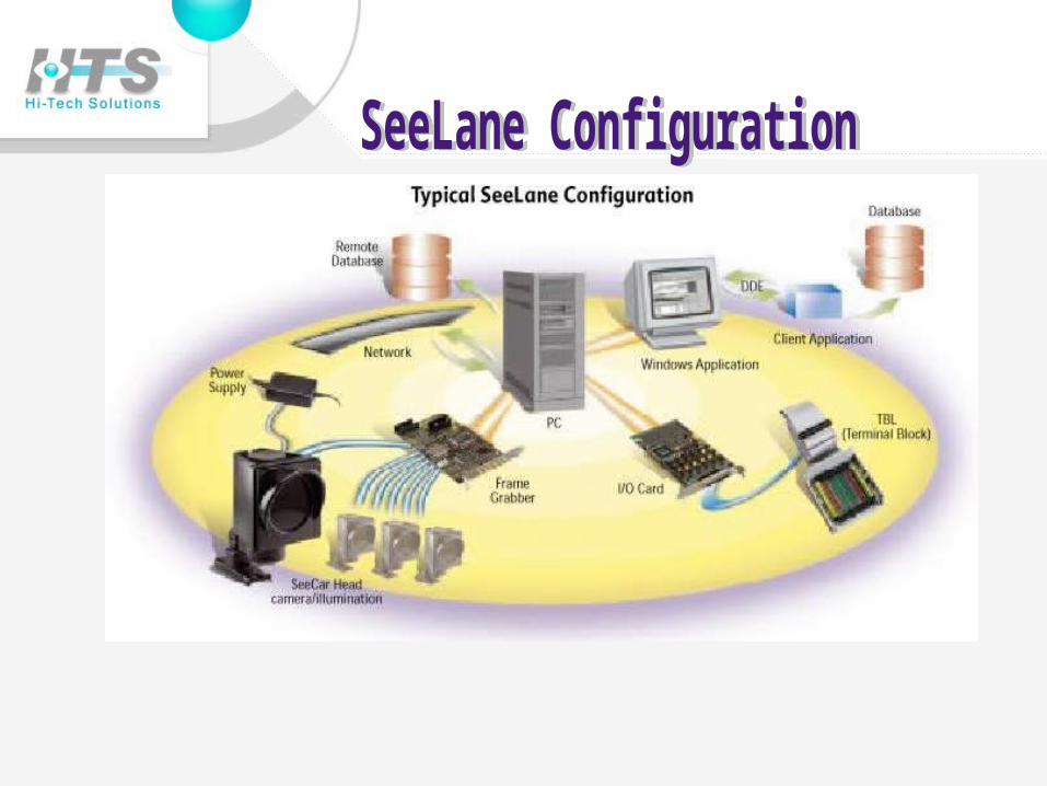
(1) System Overview
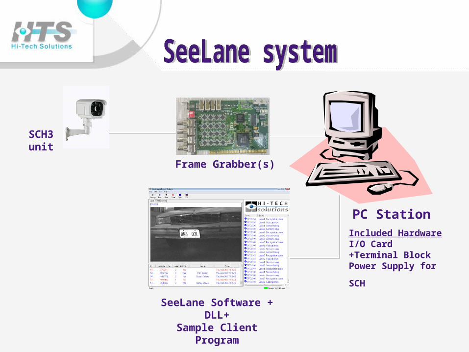
SCH3 unit Frame Grabber(s)
SeeLane Software + DLL+Sample Client Program
PC StationIncluded HardwareI/O Card +Terminal Block
Power Supply for SCH

• System includes camera/illumination units, hardware and software (application + recognition library)
• Automatically reads License Plate number
• Displays, records and transmits vehicle image and recognition results
• Can compare plate number to data base - and optionally open
gate or activate alarm

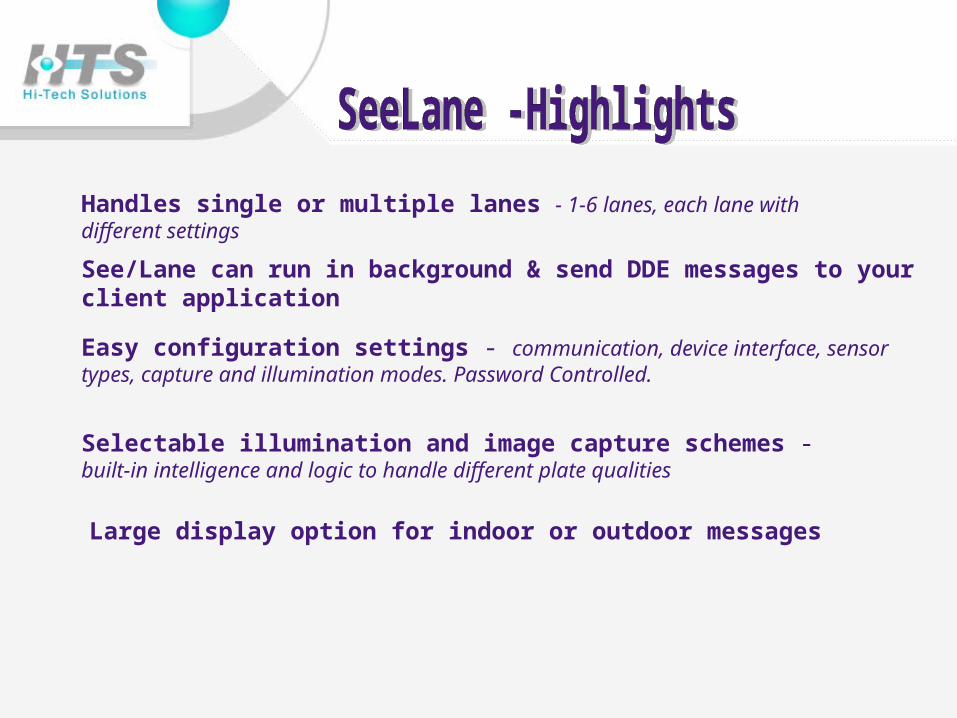
Handles single or multiple lanes - 1-6 lanes, each lane with different settings
See/Lane can run in background & send DDE messages to your client application
Easy configuration settings - communication, device interface, sensor types, capture and illumination modes. Password Controlled.
Selectable illumination and image capture schemes - built-in intelligence and logic to handle different plate qualities
Large display option for indoor or outdoor messages
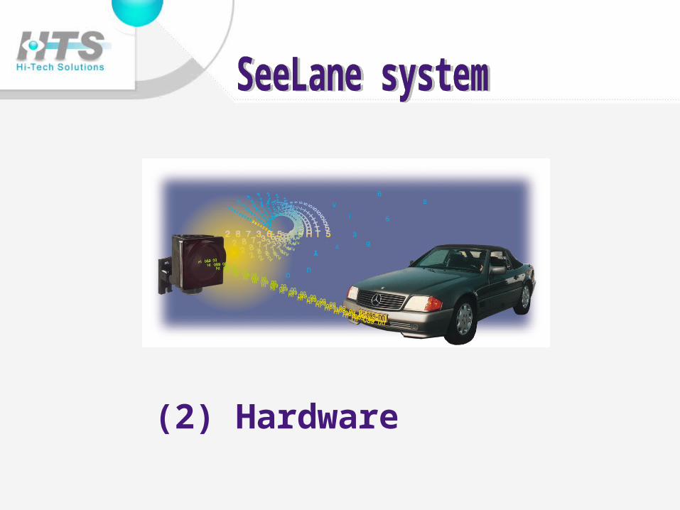
(2) Hardware
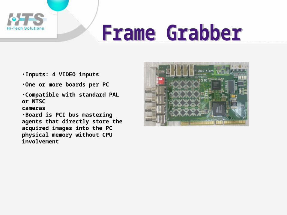
•Inputs: 4 VIDEO inputs
•One or more boards per PC
•Compatible with standard PAL or NTSC cameras •Board is PCI bus mastering agents that directly store the acquired images into the PC physical memory without CPU involvement
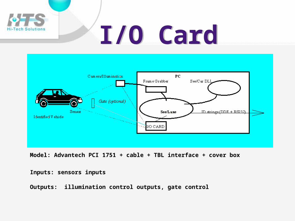
Model: Advantech PCI 1751 + cable + TBL interface + cover box
Inputs: sensors inputs
Outputs: illumination control outputs, gate control
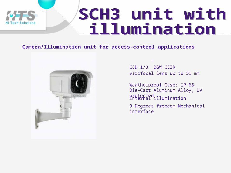
Camera/Illumination unit for access-control applications
CCD 1/3” B&W CCIR varifocal lens up to 51 mm
Weatherproof Case: IP 66 Die-Cast Aluminum Alloy, UV protected
Internal illumination
3-Degrees freedom Mechanical interface
(3) Software Interface
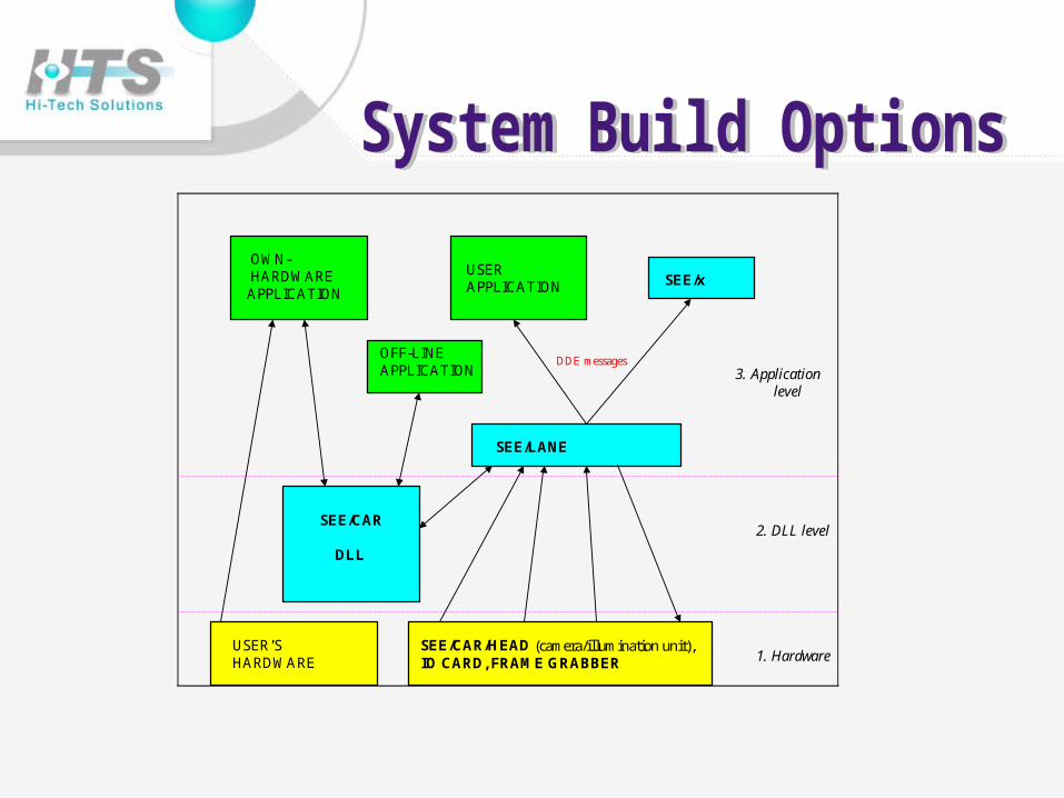
OFF-LINE APPLICATION
OWN- HARDWARE APPLICATION
USER APPLICATION SEE/x
SEE/LANE
SEE/CAR
DLL
USER’SHARDWARE
SEE/CAR/HEAD (camera/illumination unit),IO CARD, FRAME GRABBER
3. Application level
2. DLL level
1. Hardware
DDE messages
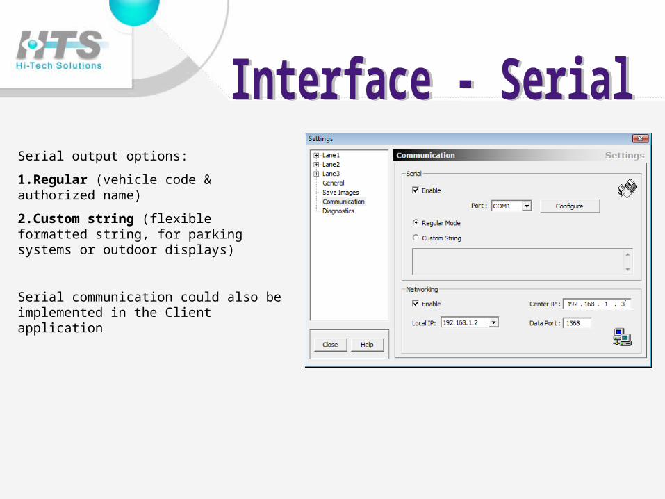
Serial output options:
1.Regular (vehicle code & authorized name)
2.Custom string (flexible formatted string, for parking systems or outdoor displays)
Serial communication could also be implemented in the Client application
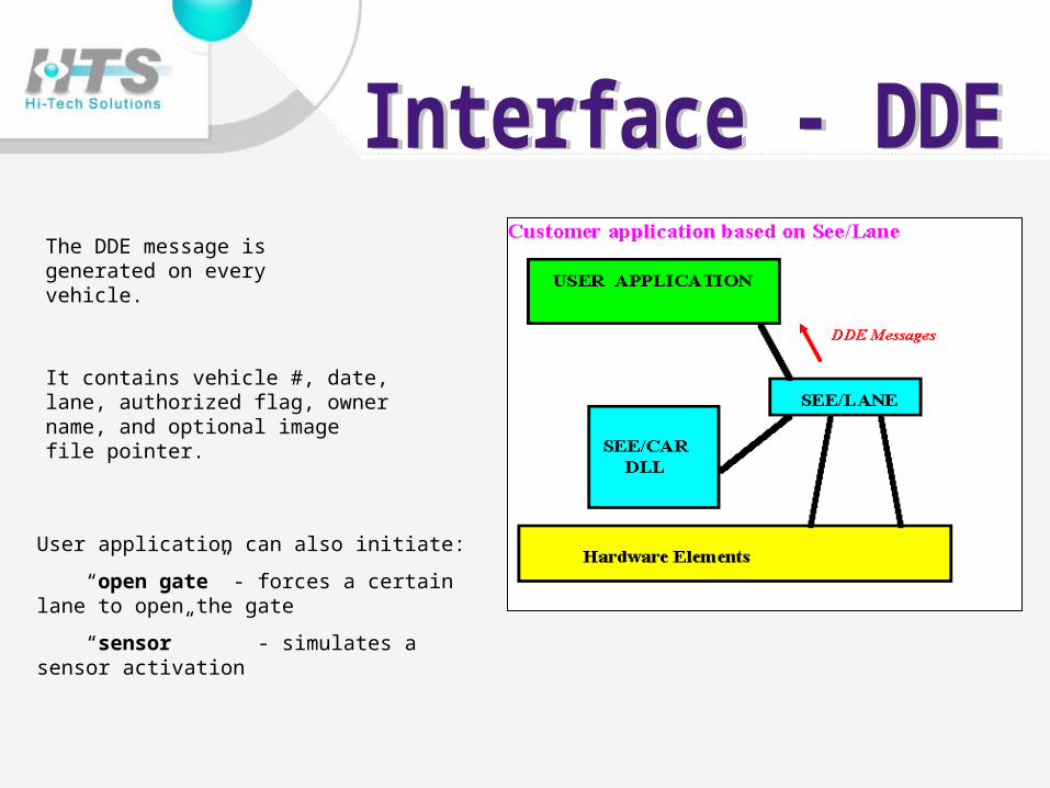
The DDE message is generated on every vehicle.
It contains vehicle #, date, lane, authorized flag, owner name, and optional image file pointer.
User application can also initiate:
“open gate” - forces a certain lane to open the gate
“sensor” - simulates a sensor activation

The DDE is IDENTICAL as in local SeeLane - only lane # is different (set by SeeLane settings or in SeeData)
Image can be transmitted - but the image’s path is better. The path can be local or absolute - according to SeeLane settings
DDE message is transmitted over the network by SeeData.
(4) Triggering
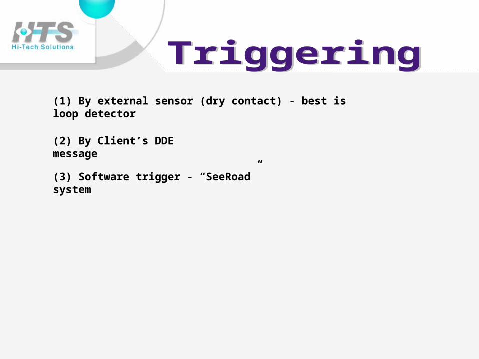
(1) By external sensor (dry contact) - best is loop detector
(3) Software trigger - “SeeRoad” system
(2) By Client’s DDE message
(5) Installing
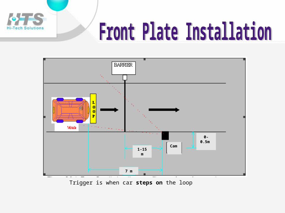
Trigger is when car steps on the loop
Cam 1-15 m
7 m
0-0.5m
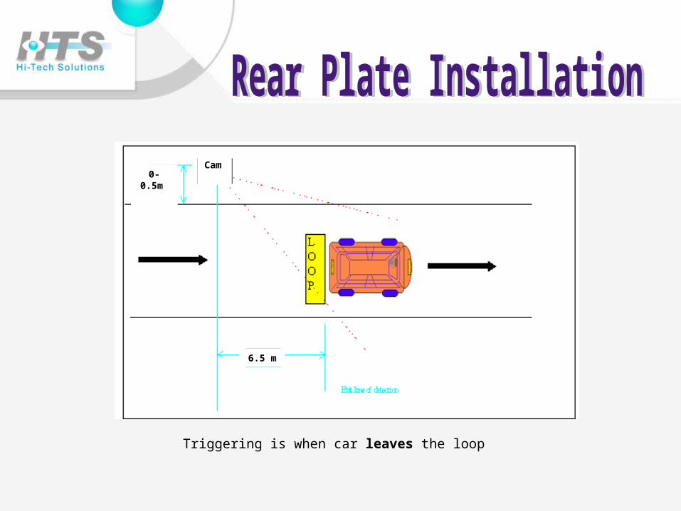
Triggering is when car leaves the loop
0-0.5m Cam
6.5 m
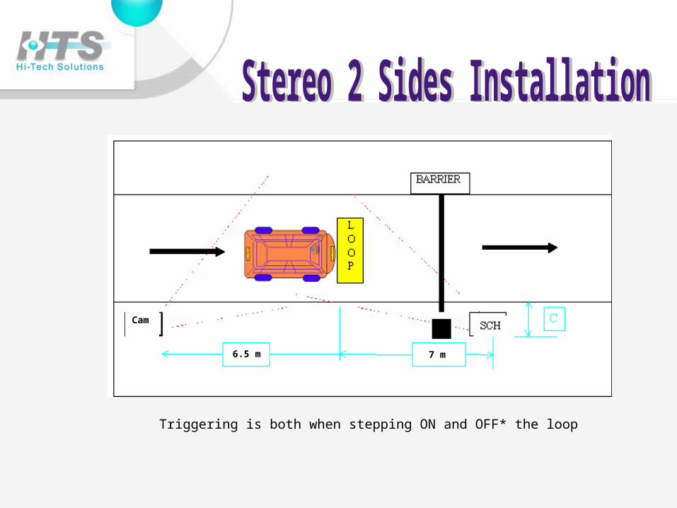
Triggering is both when stepping ON and OFF* the loop
6.5 m 7 m
Cam
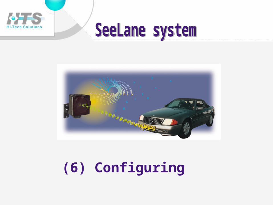
(6) Configuring
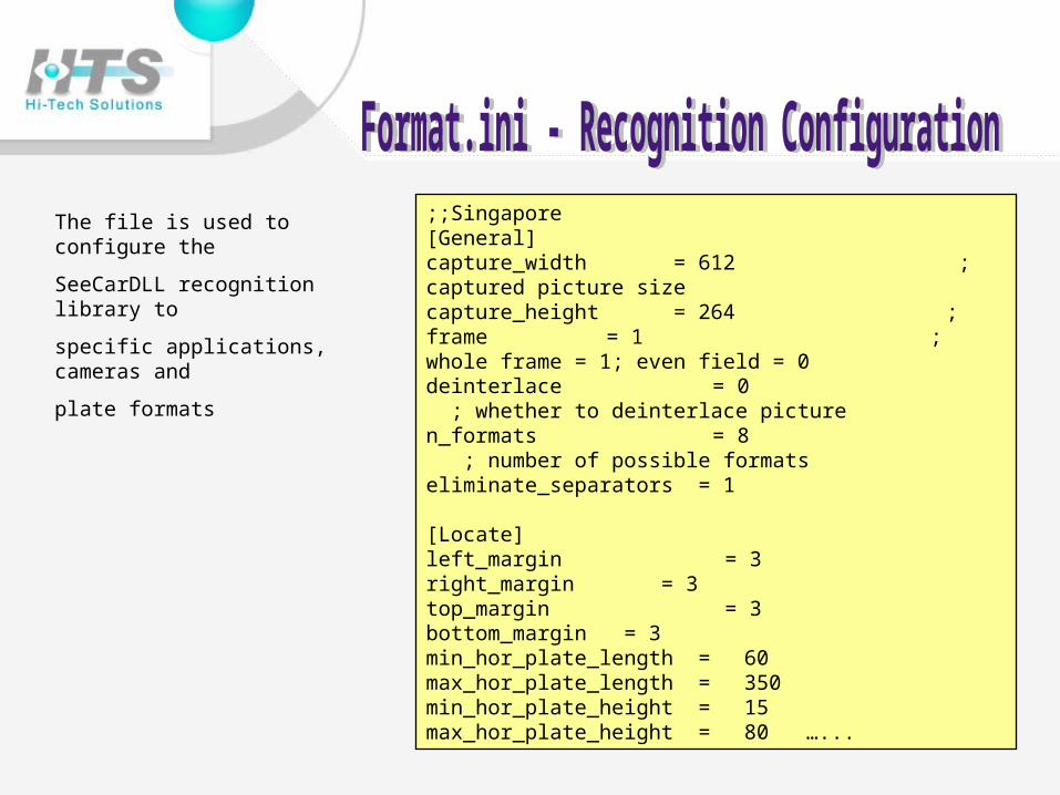
;;Singapore[General]capture_width = 612 ; captured picture sizecapture_height = 264 ;frame = 1 ; whole frame = 1; even field = 0deinterlace = 0 ; whether to deinterlace picturen_formats = 8 ; number of possible formatseliminate_separators = 1
[Locate]left_margin = 3right_margin = 3top_margin = 3bottom_margin = 3min_hor_plate_length = 60 max_hor_plate_length = 350min_hor_plate_height = 15max_hor_plate_height = 80 …...
The file is used to configure the
SeeCarDLL recognition library to
specific applications, cameras and
plate formats
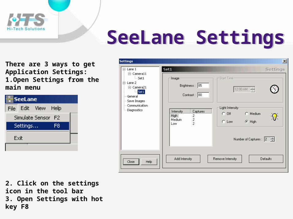
There are 3 ways to get Application Settings: 1.Open Settings from the main menu
2. Click on the settings icon in the tool bar 3. Open Settings with hot key F8
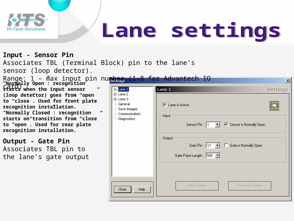
Input - Sensor Pin Associates TBL (Terminal Block) pin to the lane’s sensor (loop detector). Range: 1 – max input pin number (1-8 for Advantech IO card)
Output - Gate Pin Associates TBL pin to the lane’s gate output
“Normally Open”: recognition starts when the input sensor (loop detector) goes from “open” to “close”. Used for front plate recognition installation. “Normally Closed”: recognition starts on transition from “close” to “open”. Used for rear plate recognition installation.
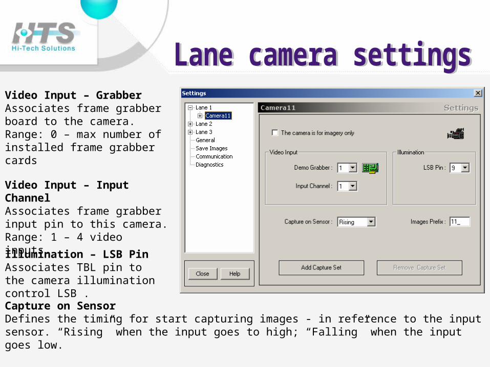
Video Input – Grabber Associates frame grabber board to the camera. Range: 0 – max number of installed frame grabber cards
Video Input – Input Channel Associates frame grabber input pin to this camera. Range: 1 – 4 video inputs.
Illumination – LSB Pin Associates TBL pin to the camera illumination control LSB .
Capture on Sensor Defines the timing for start capturing images - in reference to the input sensor. “Rising” when the input goes to high; “Falling” when the input goes low.
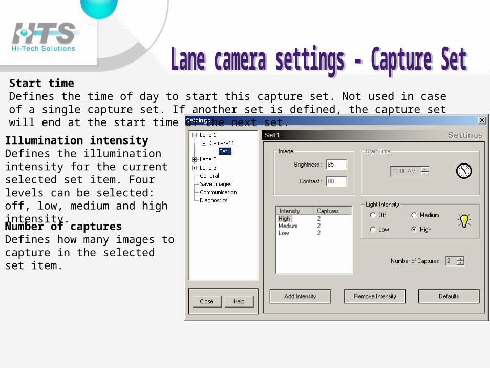
Start time Defines the time of day to start this capture set. Not used in case of a single capture set. If another set is defined, the capture set will end at the start time of the next set.
Illumination intensity Defines the illumination intensity for the current selected set item. Four levels can be selected: off, low, medium and high intensity.
Number of captures Defines how many images to capture in the selected set item.
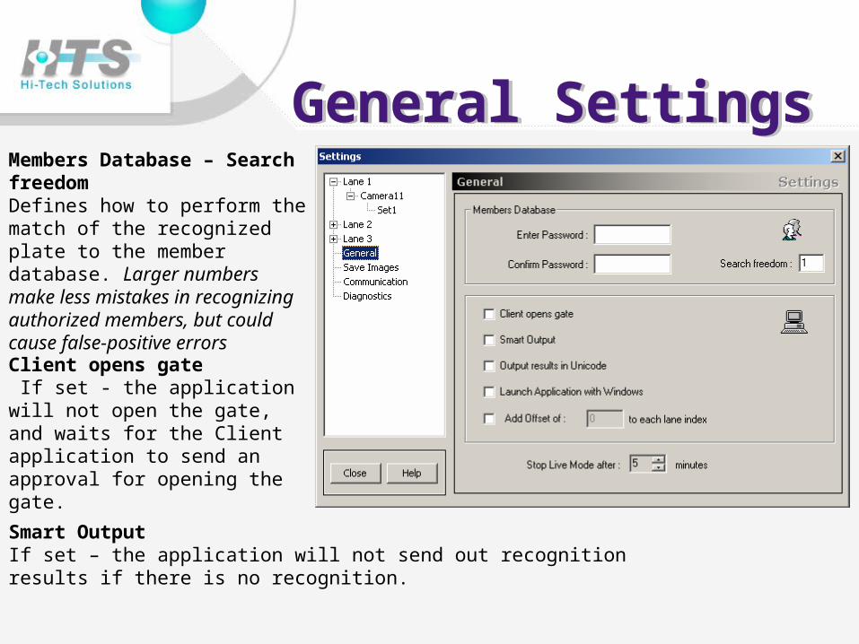
Members Database – Search freedom Defines how to perform the match of the recognized plate to the member database. Larger numbers make less mistakes in recognizing authorized members, but could cause false-positive errors
Client opens gate If set - the application will not open the gate, and waits for the Client application to send an approval for opening the gate.
Smart Output If set – the application will not send out recognition results if there is no recognition.
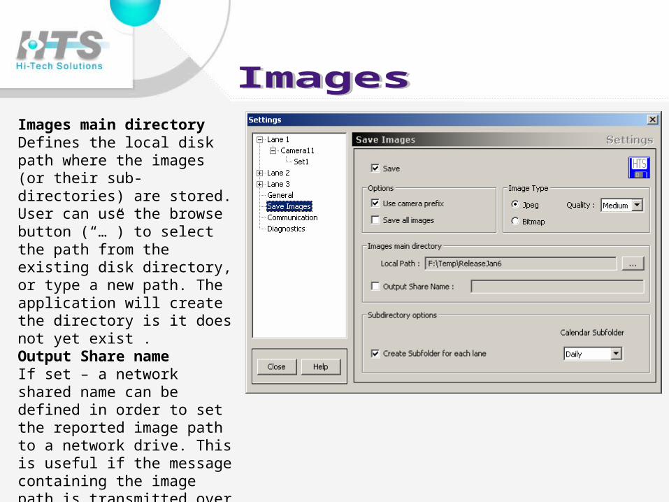
Images main directory Defines the local disk path where the images (or their sub-directories) are stored. User can use the browse button (“…”) to select the path from the existing disk directory, or type a new path. The application will create the directory is it does not yet exist .Output Share name If set – a network shared name can be defined in order to set the reported image path to a network drive. This is useful if the message containing the image path is transmitted over the network, so the remote node could access the image file name using the absolute path.

Networking.Center IP – IP address of SeeData Center Server .Data Port – communication port .Must be set the same port on SeeDataCenter Server .

The warning is recorded in the application Event log and will show as a “yellow” state in SeeMonitor.
Note that when the recognition rate increases, the application will write an information event that cancels the warning


![LPR 7320.1[1]](https://img.pdfslide.us/doc/110x75/577d36361a28ab3a6b927df7/lpr-732011.jpg)
