Embed Size (px)
Citation preview

LPR Measurement Procedure
Section 15.256 KDB Publication 890966
New Rules
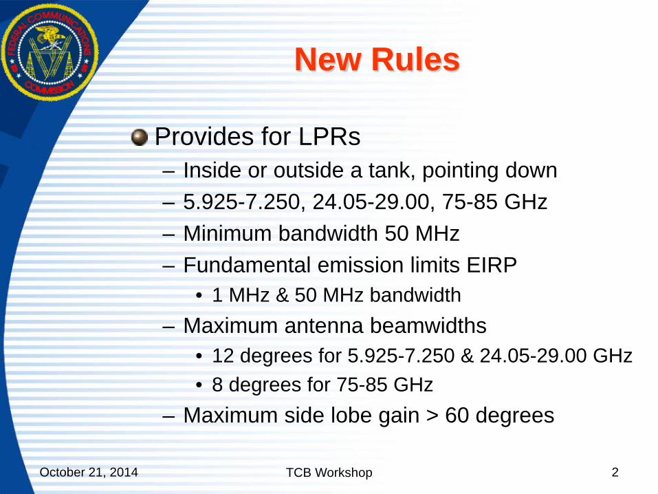
Provides for LPRs – Inside or outside a tank, pointing down – 5.925-7.250, 24.05-29.00, 75-85 GHz – Minimum bandwidth 50 MHz – Fundamental emission limits EIRP
• 1 MHz & 50 MHz bandwidth – Maximum antenna beamwidths
• 12 degrees for 5.925-7.250 & 24.05-29.00 GHz • 8 degrees for 75-85 GHz
– Maximum side lobe gain > 60 degrees
2 October 21, 2014 TCB Workshop

Measurement Procedure
KDB Publication 890966 Fundamental measurements – Radiated
• Far field, boresighted – Conducted – Harmonic mixer or downconverter required for
high frequencies – Harmonic mixer
• Fundamental BW < 2 x IF frequency – Downconverter
• Fundamental BW <= downconverter BW
3 October 21, 2014 TCB Workshop

Measurement Procedure
Fundamental bandwidth – Peak detector, 1 MHz RBW, 3 MHz VBW – Activate any frequency sweep for FMCW – Select “Max Hold” – Multiple sweeps until amplitude stabilizes – Measure 10 dB bandwidth
4 October 21, 2014 TCB Workshop

Measurement Procedure Pulsed Transmitters
Fundamental emission average power measurement – Radiated
• Boresight LPR and test antenna. – Conducted
• Connect to antenna port of LPR – Measure with power averaging (RMS) detector
and 1 MHz RBW.
5 October 21, 2014 TCB Workshop

Measurement Procedure Pulsed Transmitters
Determine F.S. or conducted power – Radiated
• Calculate F.S. using amplifier gain, antenna factor, conversion loss, etc. or
• Signal substitution. – Conducted
• Calculate conducted power from measurement using attenuation, conversion loss, cable loss, etc. or
• Signal substitution
6 October 21, 2014 TCB Workshop

Measurement Procedure Signal Substitution Method
Substitute signal generator for test ant Adjust signal generator to reference level on spectrum analyzer Calculate field strength F.S. = P + 107 + AF where: F.S. is field strength in dBuV/m P is substitution power in dBm AF is antenna factor of test antenna
7 October 21, 2014 TCB Workshop

Measurement Procedure Pulsed Transmitters
Fundamental emission peak power measurement – Measure with peak detector and 50 MHz RBW
• If 50 MHz RBW not available, measure with narrower RBW less than or greater than the PRF by a factor of 3 but no less than 1 MHz
• Calculate the maximum signal in 50 MHz with the applicable correction factor shown below:
• 20 Log (50/RBW) dB for PRF<RBW/3 • 20 Log (50/PRF) dB for PRF >3*RBW • RBW and PRF in MHz.
8 October 21, 2014 TCB Workshop

Measurement Procedure
Calculate EIRP – Radiated
• EIRP = F.S. – 104.8 + 20 Log D where F.S is field strength at far field distance D
– Conducted • EIRP = conducted power + antenna gain dBi.
9 October 21, 2014 TCB Workshop

Measurement Procedure FMCW Transmitters
TR 14-1007 attachment to KDB Publication 890966 Set analyzer span >= signal span Peak detector Measure peak amplitude – Stop signal sweep at maximum amplitude – Record value in appropriate RBW
or (cont)
10 October 21, 2014 TCB Workshop

Measurement Procedure FMCW Transmitters
Measure peak amplitude (cont) – Calculate dwell time Td = Ts / ΔF
• Ts = signal sweep time in seconds • ΔF =signal sweep freq span in MHz
– Calculate minimum RBW • RBW (Hz) = square root (10 x 106 / Td)
– Perform multiple scans in “Max Hold” or long time scan
– Record maximum peak amplitude
11 October 21, 2014 TCB Workshop

Measurement Procedure FMCW Transmitters
Determine average – Calculate average factor
• Average factor = Td / cycle time – cycle time is the total time for a complete cycle of
signal including retrace and any other latency times
• Calculate average by multiplying peak amplitude by average factor
Calculate EIRP
12 October 21, 2014 TCB Workshop

Measurement Procedure Unwanted Emissions
Emission limits of 15.209 Measurement procedure ANSI C63.10 Harmonic mixers needed for high frequencies
13 October 21, 2014 TCB Workshop

End Part 1
14 October 21, 2014 TCB Workshop

Addendum
Downconverter – Downconverts from 75-85 GHz and 92-95 GHz
range to 1 to 12 GHz range – Lower conversion loss, wider bandwidth & less
image problem than harmonic mixer
15 October 21, 2014 TCB Workshop

16 LNA
Waveguide filter
75-85 or 92-95 GHz
RF
Mixer
IF
LO
Isolator
Isolator
Frequency Multiplier-
Amp X6
IF Output
LO Input 14.25 – 16.917 GHz
W-Band Downconverter
Atten LNA WR-10 Input
75-110 GHz 21 dB gain
1-12 GHz 16 dB gain
10 dBm
October 21, 2014 TCB Workshop

17 October 21, 2014 TCB Workshop

Addendum (cont)
FMCW peak measurement – Stop sweep if possible
• Must stop at maximum frequency • Maximum signal amplitude when stopped must
be at least as high as when sweeping. – Measurement when sweeping
• Fig. A-1 single scan • Figs. A-2, A-3 multiple scans, max hold • Fig. A-4 100 sec scan, 1 MHz, 300 kHz & 100
kHz RBW
18 October 21, 2014 TCB Workshop

19
-80
-70
-60
-50
-40
-30
-20
-10
0
10
7 7.2 7.4 7.6 7.8 8 8.2 8.4 8.6 8.8 9
dBm
Freq GHz
FMCW Peak
3.36 ms scan time single scan
Figure A-1 Single scan
October 21, 2014 TCB Workshop

20
-80
-70
-60
-50
-40
-30
-20
-10
0
10
7 7.2 7.4 7.6 7.8 8 8.2 8.4 8.6 8.8 9
dBm
Freq GHz
FMCW Peak
3.36 ms scan time 10 sec max hold
Figure A-2 10 sec max hold
October 21, 2014 TCB Workshop

21
-80
-70
-60
-50
-40
-30
-20
-10
0
10
7 7.2 7.4 7.6 7.8 8 8.2 8.4 8.6 8.8 9
dBm
Freq GHz
FMCW Peak
3.36 ms scan time 100 sec max hold
Figure A-3 100 sec max hold October 21, 2014 TCB Workshop

22
-90
-80
-70
-60
-50
-40
-30
-20
-10
0
10
7 7.2 7.4 7.6 7.8 8 8.2 8.4 8.6 8.8 9
FMCW Peak
1 MHz 300 kHz 100 kHz
100 sec scan time single scan
RBW
Figure A-4 100 sec single scan October 21, 2014 TCB Workshop