Embed Size (px)
Citation preview
SECTION F:
BUILDINGIDENTIFICATIONID10 SERIES BUILDING IDENTIFICATION
ID20 SERIES BUILDING IDENTIFICATION
ID30 SERIES BUILDING IDENTIFICATION
ID40 SERIES BUILDING IDENTIFICATION
ID50 SERIES BUILDING IDENTIFICATION
ID60 SERIES BUILDING IDENTIFICATION
Some building identification signs were implemented prior
to the completion of this Universitywide Standard. These
signs have been documented and are represented in this
section. There are some building identification signs that are
unique to the Health Science campus and can be found in
Section J of this manual.

2F.2 RUTGERS UNIVERSITY SIGNAGE STANDARDS MANUAL2F.2
This Page Intentionally Left Blank

SECTION F:
ID10 SERIES
SUB-SECTION
2F.4
Questions? Please contact xxxxx
?
RUTGERS UNIVERSITY UNIVERSITYWIDE WAYFINDING AND SIGNAGE STANDARDS MANUAL
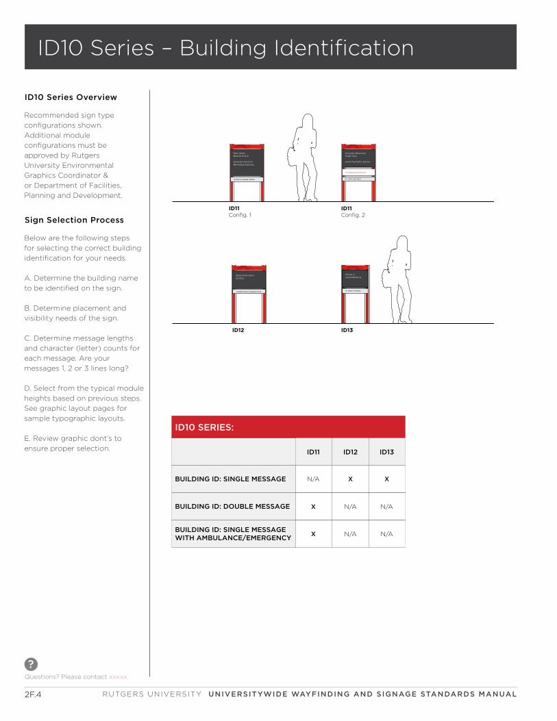
ID10 Series Overview
Recommended sign type
configurations shown.
Additional module
configurations must be
approved by Rutgers
University Environmental
Graphics Coordinator &
or Department of Facilities,
Planning and Development.
Ambulance Entrance
671 HOES LANE WEST
Acute Psychiatric Service
University Behavioral Health Care
185 SOUTH ORANGE AVENUE
New Jersey Medical School
Graduate School ofBiomedical Sciences
Medical Education Building
1 ROBERT WOOD JOHNSON PLACE
School ofDental Medicine
50 TWELFTH AVENUE
BUILDING ID:DOUBLE MESSAGE
ID10 SERIES:
BUILDING ID: SINGLE MESSAGEWITH AMBULANCE/EMERGENCY
ID11 ID12 ID13
N/A
X X
X
X
N/A
N/A
N/A N/A
BUILDING ID: SINGLE MESSAGE
BUILDING ID: DOUBLE MESSAGE
Below are the following steps
for selecting the correct building
identification for your needs.
A. Determine the building name
to be identified on the sign.
B. Determine placement and
visibility needs of the sign.
C. Determine message lengths
and character (letter) counts for
each message. Are your
messages 1, 2 or 3 lines long?
D. Select from the typical module
heights based on previous steps.
See graphic layout pages for
sample typographic layouts.
E. Review graphic dont’s to
ensure proper selection.
Sign Selection Process
ID10 Series – Building Identification
671 HOES LANE WEST
Ambulance Entrance
Acute Psychiatric Service
University Behavioral Health Care
185 SOUTH ORANGE AVENUE
New Jersey Medical School
Graduate School ofBiomedical Sciences
Configuration 1 Configuration 2
19’’
a
C
D
IB
G
H
E
F
J
K
Full length filler panels are used for single side signs only. (not shown)
Stop panel below grade line. (not shown)
PARTS
PARTS
ELEVATION
DETAIL
GRAPHIC LAYOUT BUILDING IDENTIFICATION
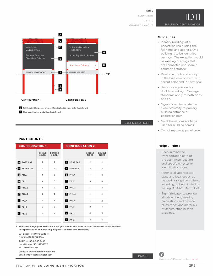
ID11
PART COUNTS
POST CAP POST CAP
SIGN POST SIGN POST
PNL.1 PNL.1
FP_1 FP_1
PNL.2 PNL.3
PNL.3 PNL.4
PNL.6FP_2
FP_2FP_3
FP_3FP_S
FP_S
2 2
2 2
1 1
4 4
1 1
1 1
12
22
24
4
2 2
2 2
2 2
8 8
2 2
2 2
24
40
04
4
CONFIGURATION 1: CONFIGURATION 2:
SINGLE SIDED
SINGLE SIDED
DOUBLE SIDED
DOUBLE SIDED
A A
B B
C C
D D
E F
F G
HI
IJ
JK
K
* *
CONFIGURATIONS
* The custom sign post extrusion is Rutgers owned and must be used. No substitutions allowed.
For specification and ordering purposes, contact EMS Delaware;
231 Executive Drive Suite 11
Newark, DE 19702 USA
Toll Free: 800-863-1496
Local Phone: 302-391-1370
Fax: 302-391-1371
Website: www.EasternMetal.com
Email: [email protected]
Helpful Hints
• Keep in mind the
transportation path of
the user when locating
and specifying exterior
identification signs.
• Refer to all appropriate
state and local codes, as
needed, for sign compliance
including, but not limited to
zoning, ADAAG, MUTCD, etc.
• Sign fabricator to provide
all relevant engineering
calculations and provide
all methods and materials
of construction in shop
drawings.
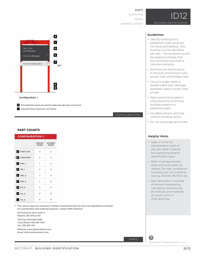
• Identify buildings at a
pedestrian scale using the
full name and address. One
building is to be identified
per sign. The exception would
be existing buildings that
are connected and share a
common entrance.
• Reinforce the brand equity
in the built environment with
accent color and Rutgers seal.
• Use as a single-sided or
double-sided sign. Message
standards apply to both sides
of sign.
• Signs should be located in
close proximity to primary
building entrance or
pedestrian path.
• No abbreviations are to be
used for building names.
• Do not rearrange panel order.
Guidelines
2F.5SECTION F: BUILDING IDENTIFICATION
Questions? Please contact xxxxx
?
185 SOUTH ORANGE AVENUE
New Jersey Medical School
Graduate School ofBiomedical Sciences
1/8"
4"1"
2'-0
"1"
4"1'
-7"
2" m
in.
4'-5
"
eq.
6"eq
.
1'-4
"
3/4"2'-6" - graphic panel
3/4"
3 1/4" 2'-1" 3 1/4"
eq. 2'-7 1/2" eq.
3'-3 1/2"
grade line
CEF
CEF
GH
GH
BA
J
ID11: Configuration 1 3/4” = 1’-0”
Plan Elevation-Single side Sign(double side panels shown dashed)
ID11: Configuration 1, 23/4” = 1’-0”
A
CD
D
BI
E
F
K
LM
LM
2F.6
ELEVATION
PARTS
ELEVATION
DETAIL
GRAPHIC LAYOUT
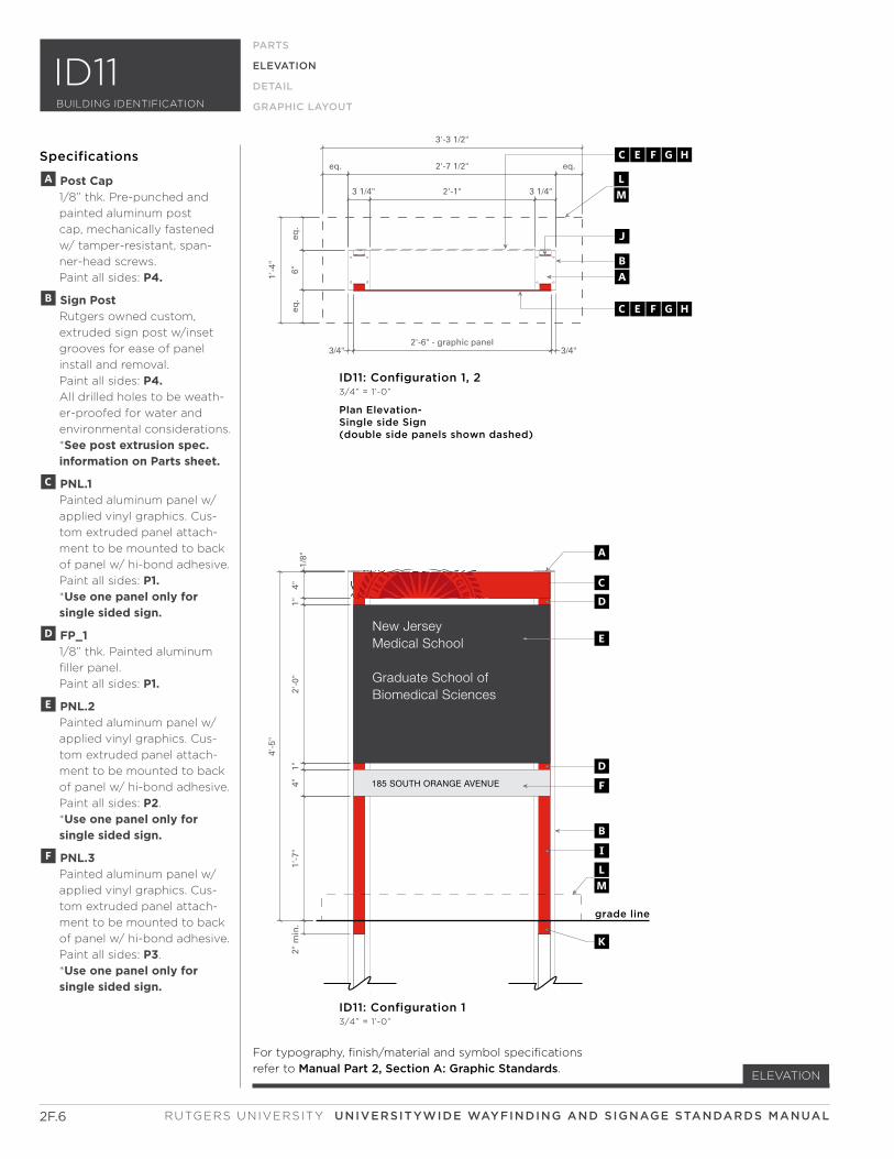
Specifications
For typography, finish/material and symbol specifications
refer to Manual Part 2, Section A: Graphic Standards.
A Post Cap 1/8” thk. Pre-punched and
painted aluminum post
cap, mechanically fastened
w/ tamper-resistant, span-
ner-head screws.
Paint all sides: P4.
B Sign Post Rutgers owned custom,
extruded sign post w/inset
grooves for ease of panel
install and removal.
Paint all sides: P4. All drilled holes to be weath-
er-proofed for water and
environmental considerations.
*See post extrusion spec. information on Parts sheet.
C PNL.1 Painted aluminum panel w/
applied vinyl graphics. Cus-
tom extruded panel attach-
ment to be mounted to back
of panel w/ hi-bond adhesive.
Paint all sides: P1. *Use one panel only for single sided sign.
D FP_1 1/8” thk. Painted aluminum
filler panel.
Paint all sides: P1.
E PNL.2 Painted aluminum panel w/
applied vinyl graphics. Cus-
tom extruded panel attach-
ment to be mounted to back
of panel w/ hi-bond adhesive.
Paint all sides: P2.
*Use one panel only for single sided sign.
F PNL.3 Painted aluminum panel w/
applied vinyl graphics. Cus-
tom extruded panel attach-
ment to be mounted to back
of panel w/ hi-bond adhesive.
Paint all sides: P3.
*Use one panel only for single sided sign.
RUTGERS UNIVERSITY UNIVERSITYWIDE WAYFINDING AND SIGNAGE STANDARDS MANUAL
ID11BUILDING IDENTIFICATION
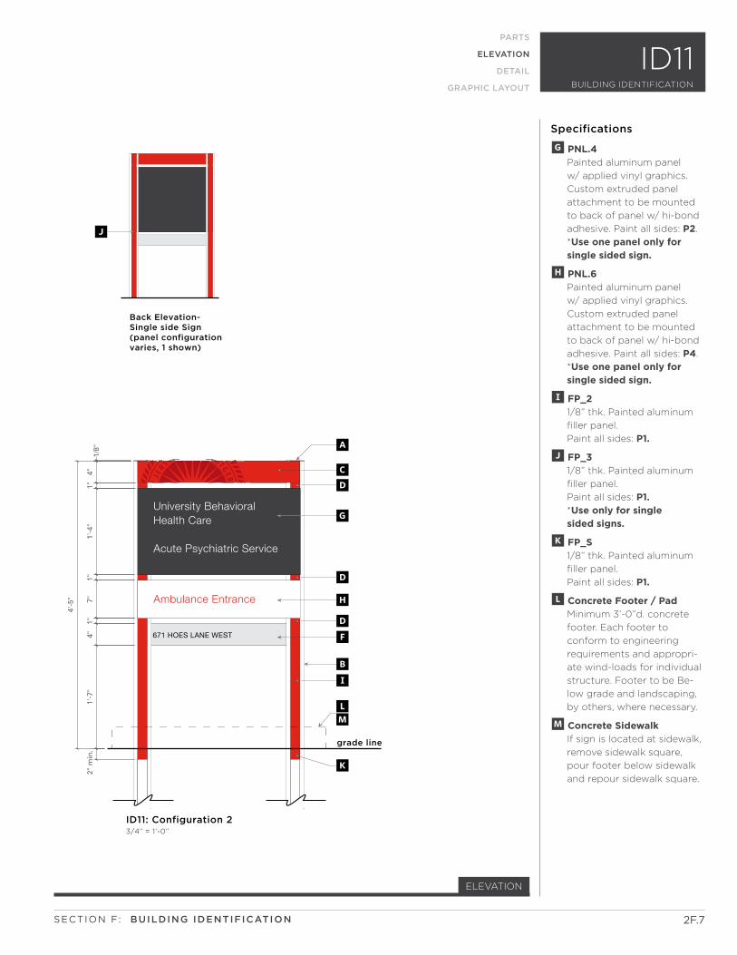
671 HOES LANE WEST
Ambulance Entrance
Acute Psychiatric Service
University Behavioral Health Care
1/8"
4"1"
1"4"
1'-7
"2"
min
.
4'-5
"
1'-4
"1"
7"
grade line
ID11: Configuration 2 3/4” = 1’-0”
A
CD
D
D
BI
G
F
H
K
LM
Back Elevation- Single side Sign(panel configurationvaries, 1 shown)
J
2F.7
ELEVATION
PARTS
ELEVATION
DETAIL
GRAPHIC LAYOUT
Specifications
G PNL.4 Painted aluminum panel
w/ applied vinyl graphics.
Custom extruded panel
attachment to be mounted
to back of panel w/ hi-bond
adhesive. Paint all sides: P2.
*Use one panel only for single sided sign.
H PNL.6 Painted aluminum panel
w/ applied vinyl graphics.
Custom extruded panel
attachment to be mounted
to back of panel w/ hi-bond
adhesive. Paint all sides: P4.
*Use one panel only for single sided sign.
I FP_2 1/8” thk. Painted aluminum
filler panel.
Paint all sides: P1.
J FP_3 1/8” thk. Painted aluminum
filler panel.
Paint all sides: P1. *Use only for single sided signs.
K FP_S 1/8” thk. Painted aluminum
filler panel.
Paint all sides: P1.
L Concrete Footer / Pad Minimum 3’-0”d. concrete
footer. Each footer to
conform to engineering
requirements and appropri-
ate wind-loads for individual
structure. Footer to be Be-
low grade and landscaping,
by others, where necessary.
M Concrete Sidewalk If sign is located at sidewalk,
remove sidewalk square,
pour footer below sidewalk
and repour sidewalk square.
SECTION F: BUILDING IDENTIFICATION
BUILDING IDENTIFICATION
ID11
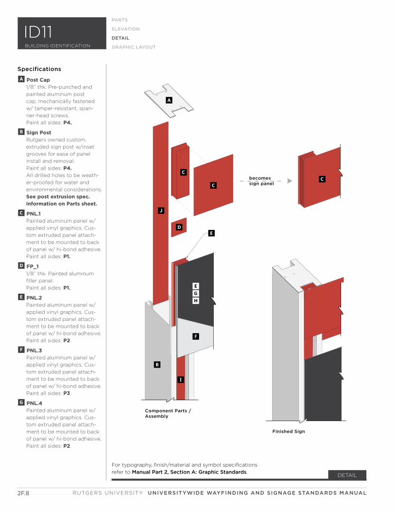
becomessign panel
Component Parts /Assembly
Finished Sign
C
A
C
D
B
I
J
C
E
F
GH
E
2F.8
DETAIL
Specifications
RUTGERS UNIVERSITY UNIVERSITYWIDE WAYFINDING AND SIGNAGE STANDARDS MANUAL
PARTS
ELEVATION
DETAIL
GRAPHIC LAYOUT
A Post Cap 1/8” thk. Pre-punched and
painted aluminum post
cap, mechanically fastened
w/ tamper-resistant, span-
ner-head screws.
Paint all sides: P4.
B Sign Post Rutgers owned custom,
extruded sign post w/inset
grooves for ease of panel
install and removal.
Paint all sides: P4. All drilled holes to be weath-
er-proofed for water and
environmental considerations.
See post extrusion spec. information on Parts sheet.
C PNL.1 Painted aluminum panel w/
applied vinyl graphics. Cus-
tom extruded panel attach-
ment to be mounted to back
of panel w/ hi-bond adhesive.
Paint all sides: P1.
D FP_1 1/8” thk. Painted aluminum
filler panel.
Paint all sides: P1.
E PNL.2 Painted aluminum panel w/
applied vinyl graphics. Cus-
tom extruded panel attach-
ment to be mounted to back
of panel w/ hi-bond adhesive.
Paint all sides: P2.
F PNL.3 Painted aluminum panel w/
applied vinyl graphics. Cus-
tom extruded panel attach-
ment to be mounted to back
of panel w/ hi-bond adhesive.
Paint all sides: P3.
G PNL.4 Painted aluminum panel w/
applied vinyl graphics. Cus-
tom extruded panel attach-
ment to be mounted to back
of panel w/ hi-bond adhesive.
Paint all sides: P2.
ID11BUILDING IDENTIFICATION
For typography, finish/material and symbol specifications
refer to Manual Part 2, Section A: Graphic Standards.
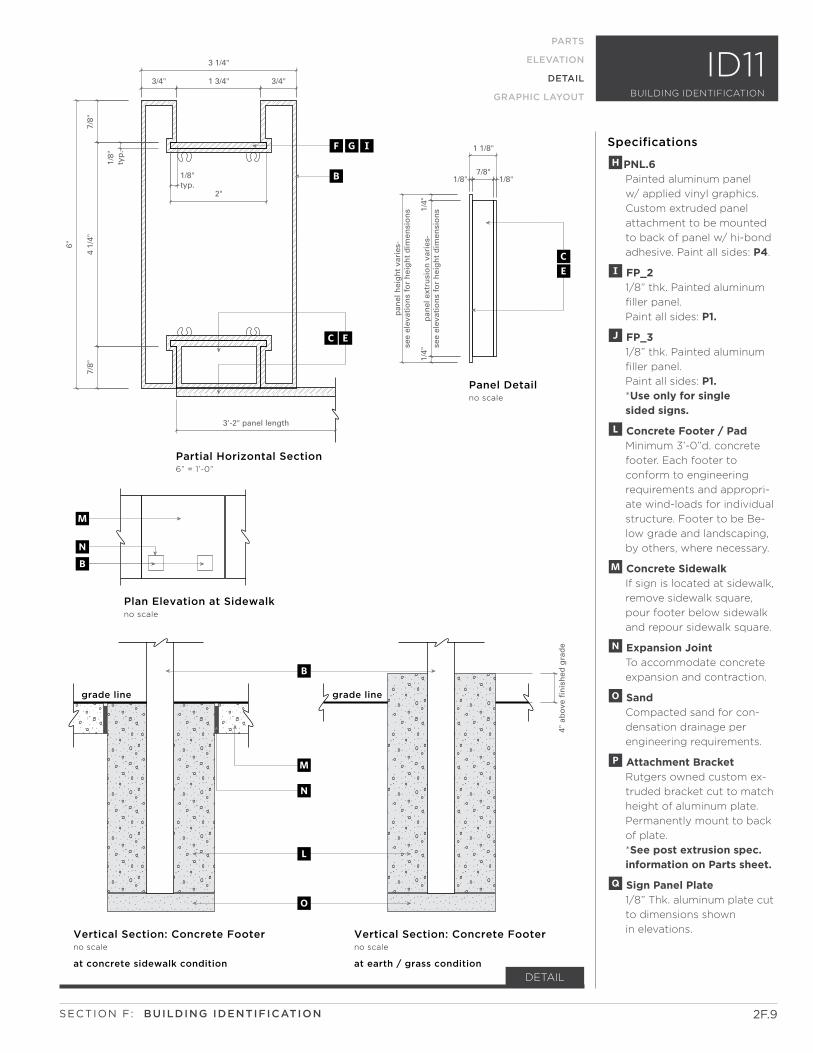
3'-2" panel length
3/4" 1 3/4" 3/4"
3 1/4"
1/8"
typ
.
7/8"
4 1/
4"7/
8"
6"
1/8"7/8"
1/8"
1 1/8"
1/4"
pan
el e
xtru
sio
n v
arie
s-se
e el
evat
ion
s fo
r h
eig
ht
dim
ensi
on
s
1/4"
pan
el h
eig
ht
vari
es-
see
elev
atio
ns
for
hei
gh
t d
imen
sio
ns
4" a
bov
e fi
nis
hed
gra
de
1/8"typ.
2"
Partial Horizontal Section 6” = 1’-0”
Vertical Section: Concrete Footerno scale
Plan Elevation at Sidewalkno scale
Panel Detail no scale
FGI
B
grade line grade line
B
m
n
o
l
B
M
N
at concrete sidewalk condition
Vertical Section: Concrete Footerno scale
at earth / grass condition
EC
CE
2F.9
DETAIL
Specifications
SECTION F: BUILDING IDENTIFICATION
PARTS
ELEVATION
DETAIL
GRAPHIC LAYOUT
HPNL.6 Painted aluminum panel
w/ applied vinyl graphics.
Custom extruded panel
attachment to be mounted
to back of panel w/ hi-bond
adhesive. Paint all sides: P4.
I FP_2 1/8” thk. Painted aluminum
filler panel.
Paint all sides: P1.
J FP_3 1/8” thk. Painted aluminum
filler panel.
Paint all sides: P1. *Use only for single sided signs.
l Concrete Footer / Pad Minimum 3’-0”d. concrete
footer. Each footer to
conform to engineering
requirements and appropri-
ate wind-loads for individual
structure. Footer to be Be-
low grade and landscaping,
by others, where necessary.
m Concrete Sidewalk If sign is located at sidewalk,
remove sidewalk square,
pour footer below sidewalk
and repour sidewalk square.
n Expansion Joint To accommodate concrete
expansion and contraction.
o Sand Compacted sand for con-
densation drainage per
engineering requirements.
p Attachment Bracket Rutgers owned custom ex-
truded bracket cut to match
height of aluminum plate.
Permanently mount to back
of plate.
*See post extrusion spec. information on Parts sheet.
q Sign Panel Plate 1/8” Thk. aluminum plate cut
to dimensions shown
in elevations.
ID11BUILDING IDENTIFICATION
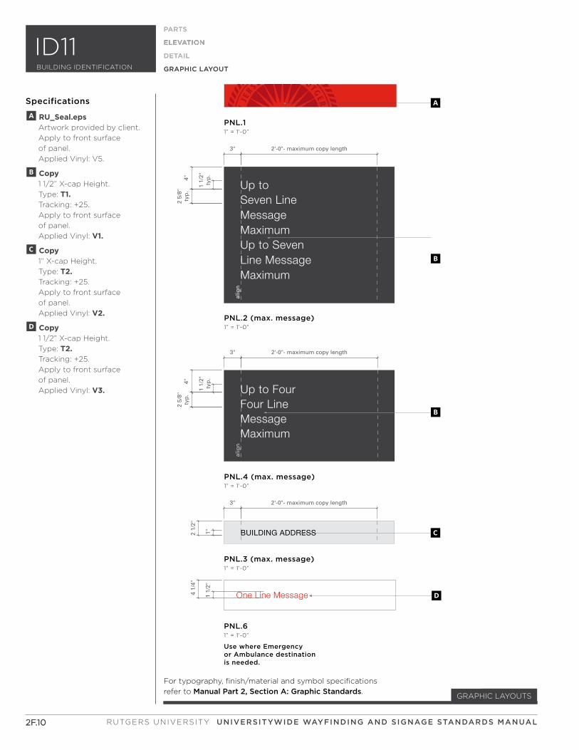
Up to Seven Line MessageMaximumUp to Seven Line MessageMaximum
BUILDING ADDRESS
One Line Message
A
B
C
D
PNL.3 (max. message)1” = 1’-0”
PNL.61” = 1’-0”
PNL.2 (max. message)1” = 1’-0”
PNL.11” = 1’-0”
alig
n
Use where Emergency or Ambulance destination is needed.
B
PNL.4 (max. message)1” = 1’-0”
alig
n
3" 2'-0"- maximum copy length
3" 2'-0"- maximum copy length
4"2
5/8"
typ
.
1 1/
2"ty
p.
1"2 1/
2"4
1/4"
1 1/
2"
3" 2'-0"- maximum copy length
4"2
5/8"
typ
.
1 1/
2"ty
p.
MessageMaximum
Up to Four Four Line
2F.10
ELEVATION
PARTS
ELEVATION
DETAIL
GRAPHIC LAYOUT
Specifications
For typography, finish/material and symbol specifications
refer to Manual Part 2, Section A: Graphic Standards.
2F.10
PARTS
ELEVATION
DETAIL
GRAPHIC LAYOUT
GRAPHIC LAYOUTS
A RU_Seal.eps Artwork provided by client.
Apply to front surface
of panel.
Applied Vinyl: V5.
B Copy 1 1/2” X-cap Height.
Type: T1. Tracking: +25.
Apply to front surface
of panel.
Applied Vinyl: V1.
C Copy 1” X-cap Height.
Type: T2. Tracking: +25.
Apply to front surface
of panel.
Applied Vinyl: V2.
D Copy 1 1/2” X-cap Height.
Type: T2. Tracking: +25.
Apply to front surface
of panel.
Applied Vinyl: V3.
RUTGERS UNIVERSITY UNIVERSITYWIDE WAYFINDING AND SIGNAGE STANDARDS MANUAL
ID11BUILDING IDENTIFICATION
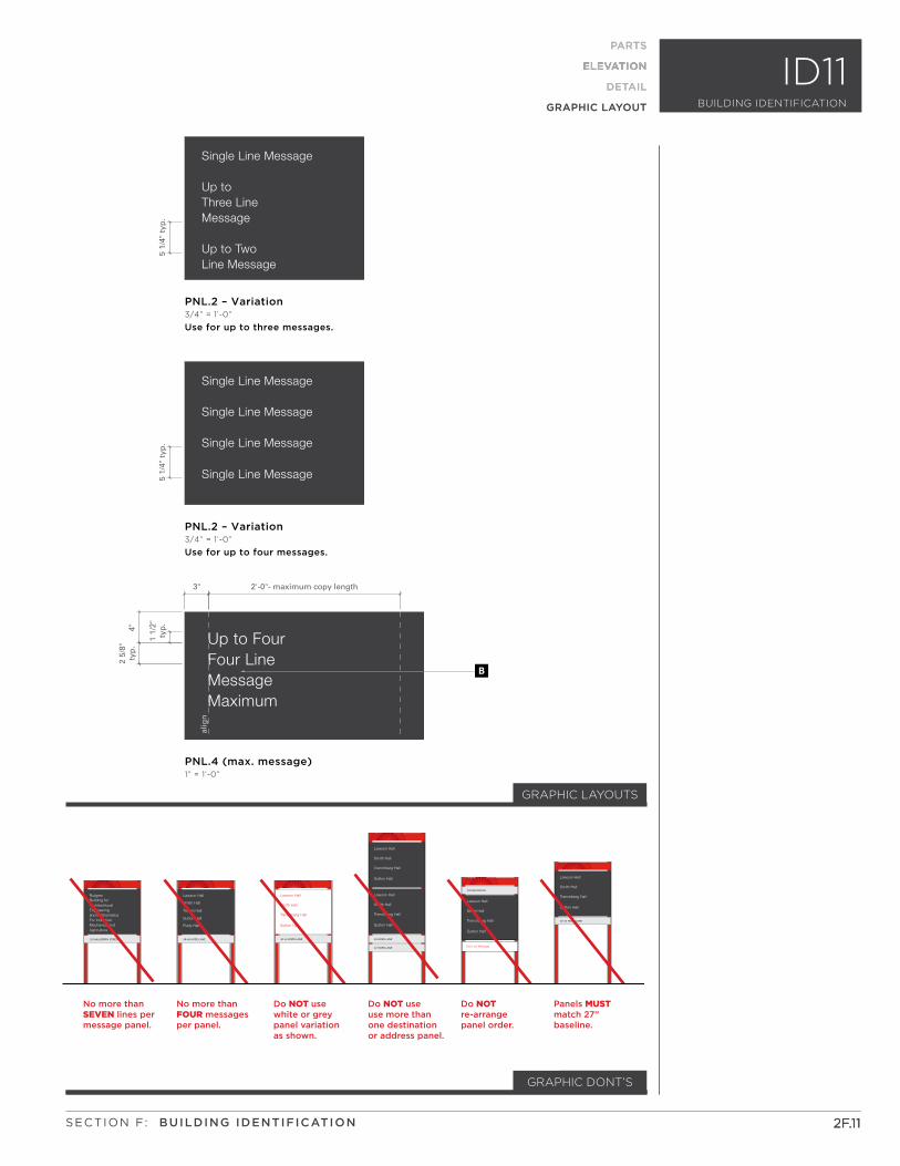
Single Line Message
Up to Three LineMessage
Up to TwoLine Message
Single Line Message
Single Line Message
Single Line Message
Single Line Message
No more than SEVEN lines per message panel.
No more than FOUR messagesper panel.
Panels MUSTmatch 27” baseline.
Do NOT use white or greypanel variation as shown.
Do NOT use use more thanone destination or address panel.
Do NOT re-arrange panel order.
Building for Rutgers
ArchitechturalEngineeringand MathematicsFor IndustrialMechanics and Agriculture
123 MULBERRY STREET 40-46 HOES LANE
225 BEIVER RD.
40 HOES LANE
42 HOES LANE
40-44 HOES LANE
Lawson Hall
Smith Hall
Trench Hall
Sutton Hall
Rudy Hall
40-44 HOES LANE
Lawson Hall
Smith Hall
Trenchberg Hall
Sutton Hall
Lawson Hall
Smith Hall
Trenchberg Hall
Sutton Hall
Lawson Hall
Smith Hall
Trenchberg Hall
Sutton Hall
Lawson Hall
Smith Hall
Trenchberg Hall
Sutton Hall
Lawson Hall
Smith Hall
Trenchberg Hall
Sutton Hall
One Line Message
PNL.2 – Variation3/4” = 1’-0”
Use for up to three messages.
PNL.2 – Variation3/4” = 1’-0”
Use for up to four messages.
B
PNL.4 (max. message)1” = 1’-0”
alig
n
5 1/
4" t
yp.
5 1/
4" t
yp.
3" 2'-0"- maximum copy length
4"2
5/8"
typ
.
1 1/
2"ty
p.
MessageMaximum
Up to Four Four Line
GRAPHIC LAYOUTS
2F.11
ELEVATION
PARTS
ELEVATION
DETAIL
GRAPHIC LAYOUT
Specifications
2F.11
PARTS
ELEVATION
DETAIL
GRAPHIC LAYOUT
GRAPHIC DONT’S
SECTION F: BUILDING IDENTIFICATION
ID11BUILDING IDENTIFICATION
2F.122F.12 RUTGERS UNIVERSITY UNIVERSITYWIDE WAYFINDING AND SIGNAGE STANDARDS MANUAL
This Page Intentionally Left Blank
PARTS
2F.132F.13
Helpful Hints
• Keep in mind the
transportation path of
the user when locating
and specifying exterior
identification signs.
• Refer to all appropriate
state and local codes, as
needed, for sign compliance
including, but not limited to
zoning, ADAAG, MUTCD, etc.
• Sign fabricator to provide
all relevant engineering
calculations and provide
all methods and materials
of construction in
shop drawings.
• Identify buildings at a
pedestrian scale using the
full name and address. One
building is to be identified
per sign. The exception would
be existing buildings that
are connected and share a
common entrance.
• Reinforce the brand equity
in the built environment with
accent color and Rutgers seal.
• Use as a single-sided or
double-sided sign. Message
standards apply to both sides
of sign.
• Signs should be located in
close proximity to primary
building entrance or
pedestrian path.
• No abbreviations are to be
used for building names.
• Do not rearrange panel order.
Guidelines
Questions? Please contact xxxxx
?
SECTION F: BUILDING IDENTIFICATION
185 SOUTH ORANGE AVENUE
Up to Two Line Message
One Line Message
27’’
a
C
D
GB
E
F
H
I
Full length filler panels are used for single side signs only. (not shown)
Stop panel below grade line. (not shown)
Configuration 1
PARTS
ELEVATION
DETAIL
GRAPHIC LAYOUT
ID12
PART COUNTS
POST CAP
SIGN POST
PNL.1
FP_1
PNL.4
PNL.3
FP_4
FP_3
FP_5
2
2
1
4
1
1
2
2
4
2
2
2
8
2
2
4
0
4
CONFIGURATION 1:
SINGLE SIDED
DOUBLE SIDED
A
B
C
D
E
F
G
H
I
*
* The custom sign post extrusion is Rutgers owned and must be used. No substitutions allowed.
For specification and ordering purposes, contact EMS Delaware;
231 Executive Drive Suite 11
Newark, DE 19702 USA
Toll Free: 800-863-1496
Local Phone: 302-391-1370
Fax: 302-391-1371
Website: www.EasternMetal.com
Email: [email protected]
CONFIGURATIONS
BUILDING IDENTIFICATION
185 SOUTH ORANGE AVENUE
Up to Two Line Message
One Line Message
1/8"
4"1"
1'-4
"1"
4"2'
-3"
2" m
in.
4'-5
"
eq.
6"eq
.
1'-4
"
3/4"2'-6" - graphic panel
3/4"
3 1/4" 2'-1" 3 1/4"
eq. 2'-7 1/2" eq.
3'-3 1/2"
grade line
ID123/4” = 1’-0”
A
CD
D
BG
E
F
I
JK
CEF
CEF
BA
H
Plan Elevation-Single side Sign(double side panels shown dashed)
ID123/4” = 1’-0”
JK
Back Elevation- Single side Sign
H
2F.14
ELEVATION
PARTS
ELEVATION
DETAIL
GRAPHIC LAYOUT
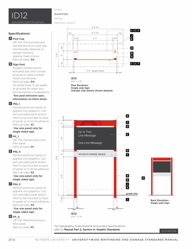
Specifications
A Post Cap 1/8” thk. Pre-punched and
painted aluminum post cap,
mechanically fastened w/
tamper-resistant,
spanner-head screws.
Paint all sides: P4.
B Sign Post Rutgers owned custom,
extruded sign post w/inset
grooves for ease of panel
install and removal.
Paint all sides: P4. All drilled holes to be weath-
er-proofed for water and
environmental considerations.
*See post extrusion spec. information on Parts sheet.
C PNL.1 Painted aluminum panel w/
applied vinyl graphics. Cus-
tom extruded panel attach-
ment to be mounted to back
of panel w/ hi-bond adhesive.
Paint all sides: P1. *Use one panel only for single sided sign.
D FP_1 1/8” thk. Painted aluminum
filler panel.
Paint all sides: P1.
E PNL.4 Painted aluminum panel w/
applied vinyl graphics. Cus-
tom extruded panel attach-
ment to be mounted to back
of panel w/ hi-bond adhesive.
Paint all sides: P2.
*Use one panel only for single sided sign.
F PNL.3 Painted aluminum panel w/
applied vinyl graphics. Cus-
tom extruded panel attach-
ment to be mounted to back
of panel w/ hi-bond adhesive.
Paint all sides: P3.
*Use one panel only for single sided sign.
G FP_4 1/8” thk. Painted aluminum
filler panel.
Paint all sides: P1. For typography, finish/material and symbol specifications
refer to Manual Part 2, Section A: Graphic Standards.
RUTGERS UNIVERSITY UNIVERSITYWIDE WAYFINDING AND SIGNAGE STANDARDS MANUAL
ID12BUILDING IDENTIFICATION
2F.15
ELEVATION
PARTS
ELEVATION
DETAIL
GRAPHIC LAYOUT
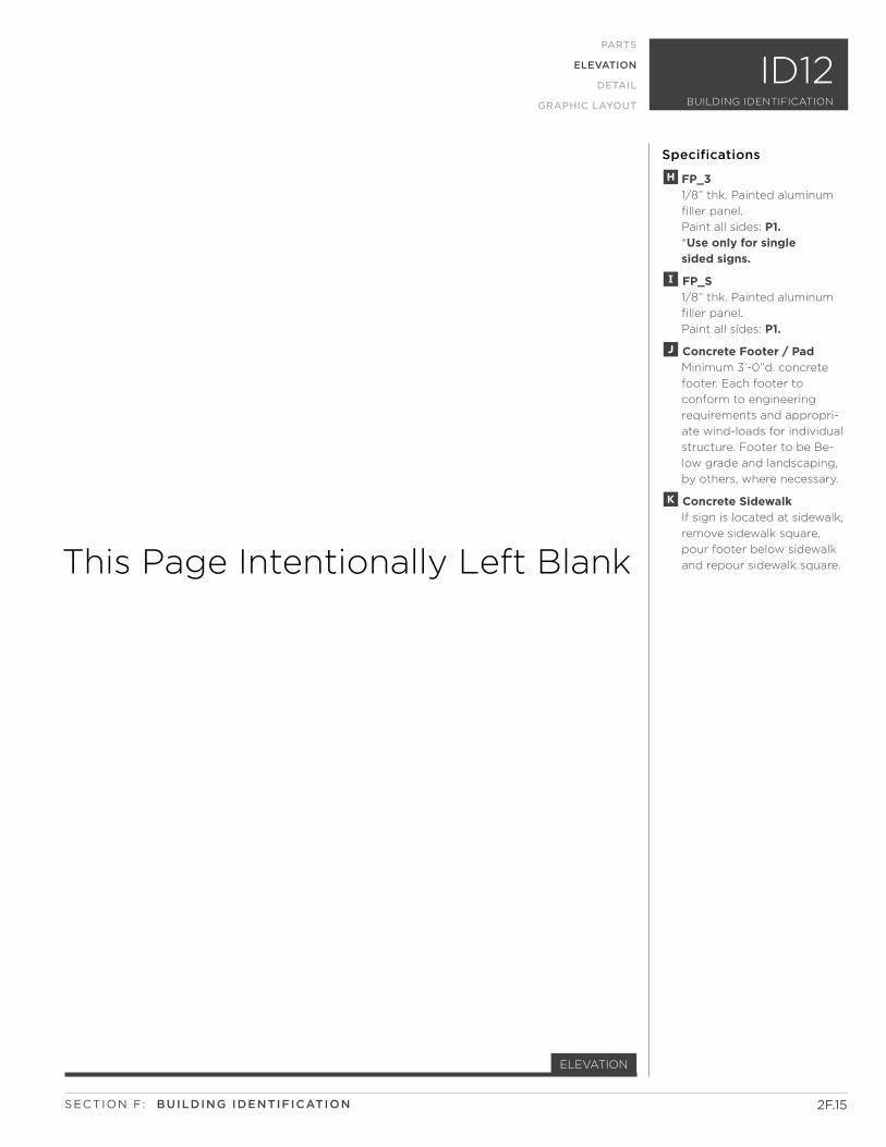
Specifications
H FP_3 1/8” thk. Painted aluminum
filler panel.
Paint all sides: P1. *Use only for single sided signs.
I FP_S 1/8” thk. Painted aluminum
filler panel.
Paint all sides: P1.
J Concrete Footer / Pad Minimum 3’-0”d. concrete
footer. Each footer to
conform to engineering
requirements and appropri-
ate wind-loads for individual
structure. Footer to be Be-
low grade and landscaping,
by others, where necessary.
K Concrete Sidewalk If sign is located at sidewalk,
remove sidewalk square,
pour footer below sidewalk
and repour sidewalk square.This Page Intentionally Left Blank
SECTION F: BUILDING IDENTIFICATION
ID12BUILDING IDENTIFICATION
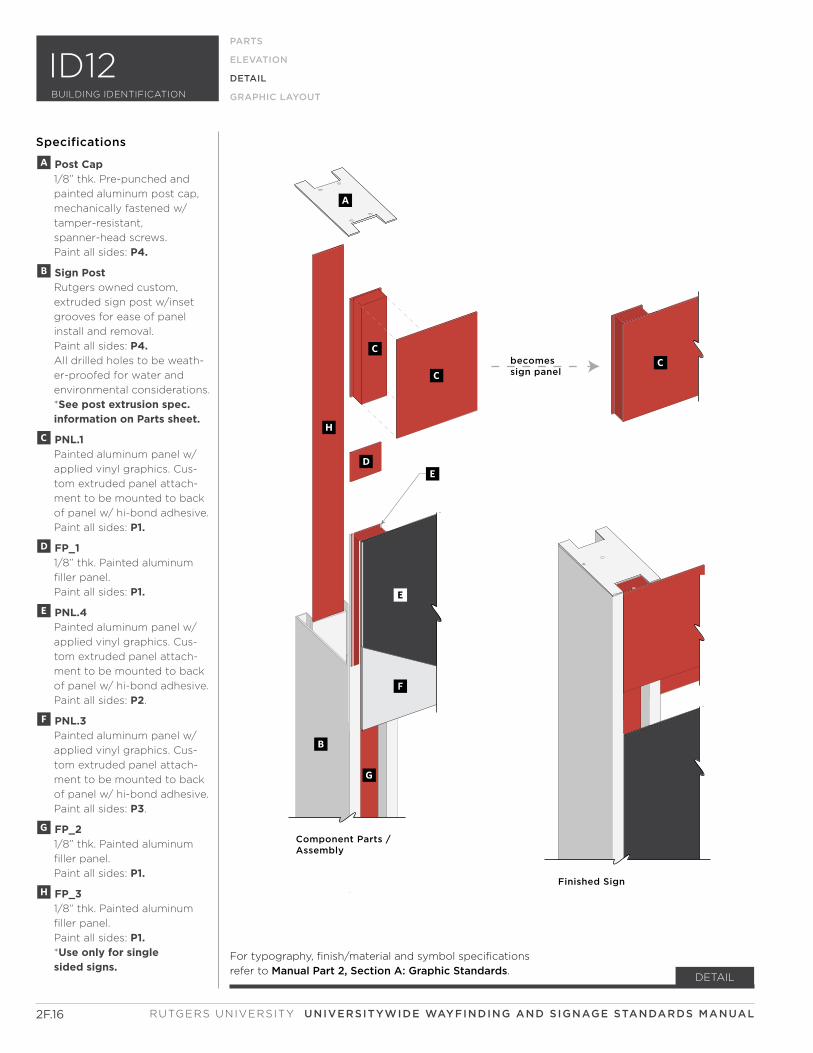
becomessign panel
Component Parts /Assembly
Finished Sign
C
A
C
D
B
G
H
C
E
F
E
2F.16
DETAIL
Specifications
RUTGERS UNIVERSITY UNIVERSITYWIDE WAYFINDING AND SIGNAGE STANDARDS MANUAL
PARTS
ELEVATION
DETAIL
GRAPHIC LAYOUT
ID12
A Post Cap 1/8” thk. Pre-punched and
painted aluminum post cap,
mechanically fastened w/
tamper-resistant,
spanner-head screws.
Paint all sides: P4.
B Sign Post Rutgers owned custom,
extruded sign post w/inset
grooves for ease of panel
install and removal.
Paint all sides: P4. All drilled holes to be weath-
er-proofed for water and
environmental considerations.
*See post extrusion spec. information on Parts sheet.
C PNL.1 Painted aluminum panel w/
applied vinyl graphics. Cus-
tom extruded panel attach-
ment to be mounted to back
of panel w/ hi-bond adhesive.
Paint all sides: P1.
D FP_1 1/8” thk. Painted aluminum
filler panel.
Paint all sides: P1.
E PNL.4 Painted aluminum panel w/
applied vinyl graphics. Cus-
tom extruded panel attach-
ment to be mounted to back
of panel w/ hi-bond adhesive.
Paint all sides: P2.
F PNL.3 Painted aluminum panel w/
applied vinyl graphics. Cus-
tom extruded panel attach-
ment to be mounted to back
of panel w/ hi-bond adhesive.
Paint all sides: P3.
G FP_2 1/8” thk. Painted aluminum
filler panel.
Paint all sides: P1.
H FP_3 1/8” thk. Painted aluminum
filler panel.
Paint all sides: P1. *Use only for single sided signs.
BUILDING IDENTIFICATION
For typography, finish/material and symbol specifications
refer to Manual Part 2, Section A: Graphic Standards.
3'-2" panel length
3/4" 1 3/4" 3/4"
3 1/4"
1/8"
typ
.
7/8"
4 1/
4"7/
8"
6"
1/8"7/8"
1/8"
1 1/8"
1/4"
pan
el e
xtru
sio
n v
arie
s-se
e el
evat
ion
s fo
r h
eig
ht
dim
ensi
on
s
1/4"
pan
el h
eig
ht
vari
es-
see
elev
atio
ns
for
hei
gh
t d
imen
sio
ns
4" a
bov
e fi
nis
hed
gra
de
1/8"typ.
2"
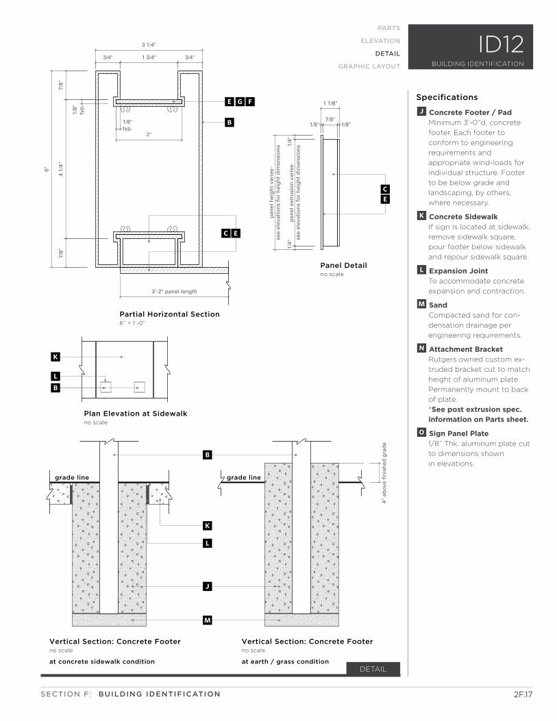
Partial Horizontal Section 6” = 1’-0”
Vertical Section: Concrete Footerno scale
Plan Elevation at Sidewalkno scale
Panel Detail no scale
EGF
B
grade line grade line
B
K
L
M
J
B
K
L
at concrete sidewalk condition
Vertical Section: Concrete Footerno scale
at earth / grass condition
EC
CE
2F.17
DETAIL
Specifications
SECTION F: BUILDING IDENTIFICATION
PARTS
ELEVATION
DETAIL
GRAPHIC LAYOUT
ID12
J Concrete Footer / Pad Minimum 3’-0”d. concrete
footer. Each footer to
conform to engineering
requirements and
appropriate wind-loads for
individual structure. Footer
to be below grade and
landscaping, by others,
where necessary.
K Concrete Sidewalk If sign is located at sidewalk,
remove sidewalk square,
pour footer below sidewalk
and repour sidewalk square.
L Expansion Joint To accommodate concrete
expansion and contraction.
M Sand Compacted sand for con-
densation drainage per
engineering requirements.
N Attachment Bracket Rutgers owned custom ex-
truded bracket cut to match
height of aluminum plate.
Permanently mount to back
of plate.
*See post extrusion spec. information on Parts sheet.
O Sign Panel Plate 1/8” Thk. aluminum plate cut
to dimensions shown
in elevations.
BUILDING IDENTIFICATION
BUILDING ADDRESS
Up to TwoLine Message
Up to Two Line Message
Up to TwoLine Message
Up to Two Line Message
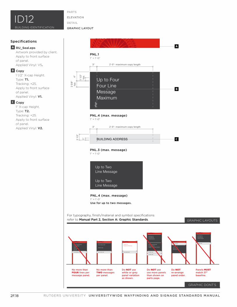
No more than FOUR lines per message panel.
No more than TWO messagesper panel.
Panels MUSTmatch 27” baseline.
Do NOT use white or greypanel variation as shown.
Do NOT use use more panelsthan shown onparts page.
Do NOT re-arrange panel order.
123 MULBERRY STREET
HealthSciencesInstitute
Environmental andOccupational
40-44 HOES LANE
225 BEIVER RD.
40 HOES LANE
42 HOES LANE
40 HOES LANE
Trenchberg Hall
Sutton Hall
40-44 HOES LANE
Center for Advanced Medicine
Health Sciences Institute
Environmental andOccupational
Advancement
Institute for Educational
Advancement
Institute for Educational
Advancement
Institute for Educational
A
B
C
PNL.3 (max. message)1” = 1’-0”
PNL.4 (max. message)1” = 1’-0”
PNL.11” = 1’-0”
PNL.4 (max. message)1” = 1’-0”
Use for up to two messages.
alig
n
3" 2'-0"- maximum copy length
1"2 1/
2"
3" 2'-0"- maximum copy length
4"2
5/8"
typ
.
1 1/
2"ty
p.
MessageMaximum
Up to Four Four Line
2F.18
ELEVATION
PARTS
ELEVATION
DETAIL
GRAPHIC LAYOUT
Specifications
2F.18
PARTS
ELEVATION
DETAIL
GRAPHIC LAYOUT
GRAPHIC DONT’S
For typography, finish/material and symbol specifications
refer to Manual Part 2, Section A: Graphic Standards. GRAPHIC LAYOUTS
A RU_Seal.eps Artwork provided by client.
Apply to front surface
of panel.
Applied Vinyl: V5.
B Copy 1 1/2” X-cap Height.
Type: T1. Tracking: +25.
Apply to front surface
of panel.
Applied Vinyl: V1.
C Copy 1” X-cap Height.
Type: T2. Tracking: +25.
Apply to front surface
of panel.
Applied Vinyl: V2.
RUTGERS UNIVERSITY UNIVERSITYWIDE WAYFINDING AND SIGNAGE STANDARDS MANUAL
ID12BUILDING IDENTIFICATION
PARTS
50 TWELFTH AVENUE
Up to Two Line Message
One Line Message
A
C
D
GB
E
H
I
Full length filler panels are used for single side signs only. (not shown)
Stop panel below grade line. (not shown)
27’’F
Configuration 1
PARTS
ELEVATION
DETAIL
GRAPHIC LAYOUT
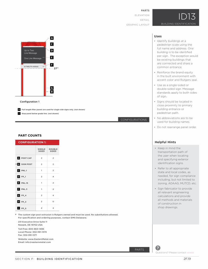
PART COUNTS
POST CAP
SIGN POST
PNL.1
FP_1
PNL.15
PNL.3
FP_4
FP_3
FP_S
2
2
1
2
1
1
2
2
4
2
2
2
4
2
2
4
0
4
CONFIGURATION 1:
SINGLE SIDED
DOUBLE SIDED
A
B
C
D
E
F
G
H
I
*
* The custom sign post extrusion is Rutgers owned and must be used. No substitutions allowed.
For specification and ordering purposes, contact EMS Delaware;
231 Executive Drive Suite 11
Newark, DE 19702 USA
Toll Free: 800-863-1496
Local Phone: 302-391-1370
Fax: 302-391-1371
Website: www.EasternMetal.com
Email: [email protected]
CONFIGURATIONS
ID13
Questions? Please contact xxxxx
?
BUILDING IDENTIFICATION
2F.19SECTION F: BUILDING IDENTIFICATION
Helpful Hints
• Keep in mind the
transportation path of
the user when locating
and specifying exterior
identification signs.
• Refer to all appropriate
state and local codes, as
needed, for sign compliance
including, but not limited to
zoning, ADAAG, MUTCD, etc.
• Sign fabricator to provide
all relevant engineering
calculations and provide
all methods and materials
of construction in
shop drawings.
Uses
• Identify buildings at a
pedestrian scale using the
full name and address. One
building is to be identified
per sign. The exception would
be existing buildings that
are connected and share a
common entrance.
• Reinforce the brand equity
in the built environment with
accent color and Rutgers seal.
• Use as a single-sided or
double-sided sign. Message
standards apply to both sides
of sign.
• Signs should be located in
close proximity to primary
building entrance or
pedestrian path.
• No abbreviations are to be
used for building names.
• Do not rearrange panel order.
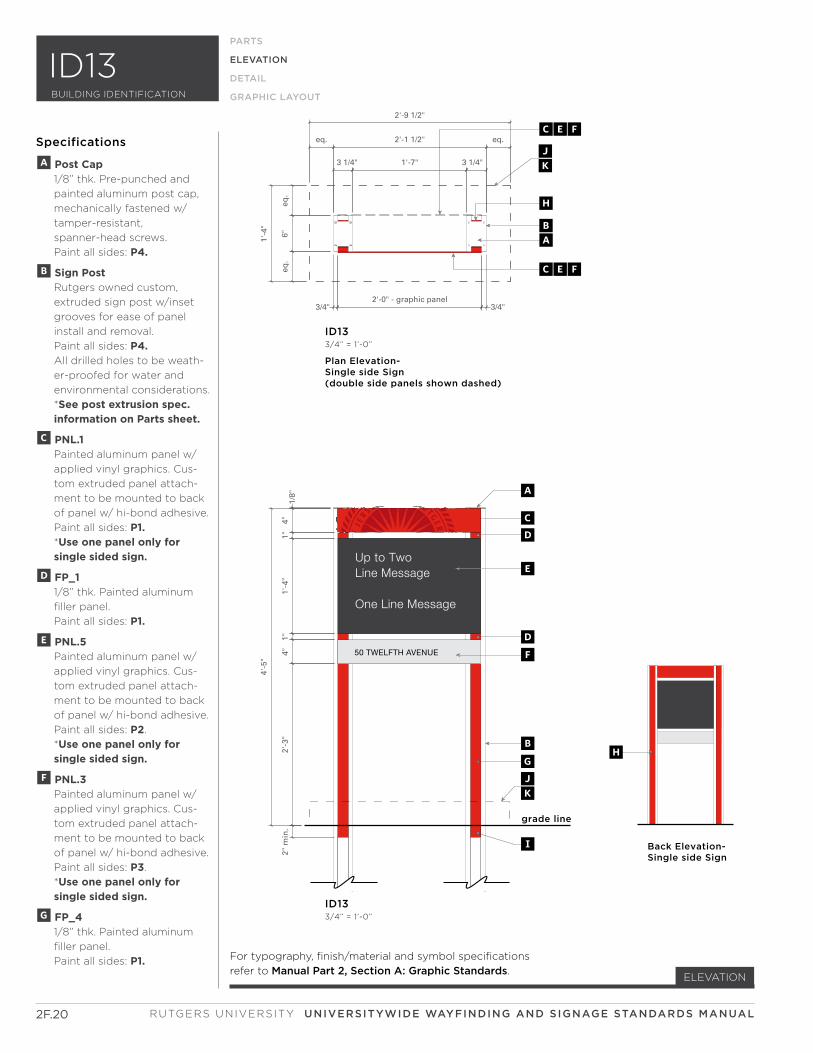
50 TWELFTH AVENUE
Up to Two Line Message
One Line Message
1/8"
4"1"
1'-4
"1"
4"2'
-3"
2" m
in.
4'-5
"
eq.
6"eq
.
1'-4
"
3/4"2'-0" - graphic panel
3/4"
3 1/4" 1'-7" 3 1/4"
eq. 2'-1 1/2" eq.
2'-9 1/2"
grade line
ID133/4” = 1’-0”
A
CD
D
BG
E
F
I
JK
CEF
CEF
BA
H
Plan Elevation-Single side Sign(double side panels shown dashed)
ID133/4” = 1’-0”
JK
Back Elevation- Single side Sign
H
2F.20
ELEVATION
PARTS
ELEVATION
DETAIL
GRAPHIC LAYOUT
Specifications
A Post Cap 1/8” thk. Pre-punched and
painted aluminum post cap,
mechanically fastened w/
tamper-resistant,
spanner-head screws.
Paint all sides: P4.
B Sign Post Rutgers owned custom,
extruded sign post w/inset
grooves for ease of panel
install and removal.
Paint all sides: P4. All drilled holes to be weath-
er-proofed for water and
environmental considerations.
*See post extrusion spec. information on Parts sheet.
C PNL.1 Painted aluminum panel w/
applied vinyl graphics. Cus-
tom extruded panel attach-
ment to be mounted to back
of panel w/ hi-bond adhesive.
Paint all sides: P1. *Use one panel only for single sided sign.
D FP_1 1/8” thk. Painted aluminum
filler panel.
Paint all sides: P1.
E PNL.5 Painted aluminum panel w/
applied vinyl graphics. Cus-
tom extruded panel attach-
ment to be mounted to back
of panel w/ hi-bond adhesive.
Paint all sides: P2.
*Use one panel only for single sided sign.
F PNL.3 Painted aluminum panel w/
applied vinyl graphics. Cus-
tom extruded panel attach-
ment to be mounted to back
of panel w/ hi-bond adhesive.
Paint all sides: P3.
*Use one panel only for single sided sign.
G FP_4 1/8” thk. Painted aluminum
filler panel.
Paint all sides: P1. For typography, finish/material and symbol specifications
refer to Manual Part 2, Section A: Graphic Standards.
RUTGERS UNIVERSITY UNIVERSITYWIDE WAYFINDING AND SIGNAGE STANDARDS MANUAL
ID13BUILDING IDENTIFICATION

2F.21
ELEVATION
PARTS
ELEVATION
DETAIL
GRAPHIC LAYOUT
Specifications
HFP_3 1/8” thk. Painted aluminum
filler panel.
Paint all sides: P1. *Use only for single sided signs.
I FP_S 1/8” thk. Painted aluminum
filler panel.
Paint all sides: P1.
J Concrete Footer / Pad Minimum 3’-0”d. concrete
footer. Each footer to
conform to engineering
requirements and
appropriate wind-loads for
individual structure.
Footer to be below grade
and landscaping, by others,
where necessary.
K Concrete Sidewalk If sign is located at sidewalk,
remove sidewalk square,
pour footer below sidewalk
and repour sidewalk square.This Page Intentionally Left Blank
SECTION F: BUILDING IDENTIFICATION
ID13BUILDING IDENTIFICATION
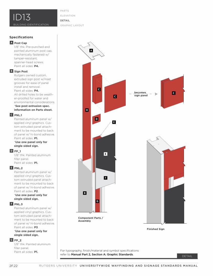
becomessign panel
Component Parts /Assembly
Finished Sign
C
A
C
D
B
G
H
C
E
F
E
2F.22
DETAIL
Specifications
RUTGERS UNIVERSITY UNIVERSITYWIDE WAYFINDING AND SIGNAGE STANDARDS MANUAL
PARTS
ELEVATION
DETAIL
GRAPHIC LAYOUT
A Post Cap 1/8” thk. Pre-punched and
painted aluminum post cap,
mechanically fastened w/
tamper-resistant,
spanner-head screws.
Paint all sides: P4.
B Sign Post Rutgers owned custom,
extruded sign post w/inset
grooves for ease of panel
install and removal.
Paint all sides: P4. All drilled holes to be weath-
er-proofed for water and
environmental considerations.
*See post extrusion spec. information on Parts sheet.
C PNL.1 Painted aluminum panel w/
applied vinyl graphics. Cus-
tom extruded panel attach-
ment to be mounted to back
of panel w/ hi-bond adhesive.
Paint all sides: P1. *Use one panel only for single sided sign.
D FP_1 1/8” thk. Painted aluminum
filler panel.
Paint all sides: P1.
E PNL.2 Painted aluminum panel w/
applied vinyl graphics. Cus-
tom extruded panel attach-
ment to be mounted to back
of panel w/ hi-bond adhesive.
Paint all sides: P2.
*Use one panel only for single sided sign.
F PNL.3 Painted aluminum panel w/
applied vinyl graphics. Cus-
tom extruded panel attach-
ment to be mounted to back
of panel w/ hi-bond adhesive.
Paint all sides: P3.
*Use one panel only for single sided sign.
G FP_2 1/8” thk. Painted aluminum
filler panel.
Paint all sides: P1.
ID13BUILDING IDENTIFICATION
For typography, finish/material and symbol specifications
refer to Manual Part 2, Section A: Graphic Standards.
3'-2" panel length
3/4" 1 3/4" 3/4"
3 1/4"
1/8"
typ
.
7/8"
4 1/
4"7/
8"
6"
1/8"7/8"
1/8"
1 1/8"
1/4"
pan
el e
xtru
sio
n v
arie
s-se
e el
evat
ion
s fo
r h
eig
ht
dim
ensi
on
s
1/4"
pan
el h
eig
ht
vari
es-
see
elev
atio
ns
for
hei
gh
t d
imen
sio
ns
4" a
bov
e fi
nis
hed
gra
de
1/8"typ.
2"
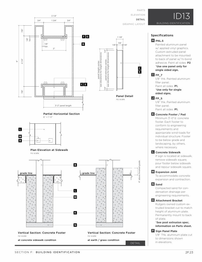
Partial Horizontal Section 6” = 1’-0”
Vertical Section: Concrete Footerno scale
Plan Elevation at Sidewalkno scale
Panel Detail no scale
FG
B
grade line grade line
B
L
M
N
K
B
L
M
at concrete sidewalk condition
Vertical Section: Concrete Footerno scale
at earth / grass condition
EC
CE
2F.23
DETAIL
Specifications
SECTION F: BUILDING IDENTIFICATION
PARTS
ELEVATION
DETAIL
GRAPHIC LAYOUT
H PNL.5 Painted aluminum panel
w/ applied vinyl graphics.
Custom extruded panel
attachment to be mounted
to back of panel w/ hi-bond
adhesive. Paint all sides: P2.
*Use one panel only for single sided sign.
I FP_7 1/8” thk. Painted aluminum
filler panel.
Paint all sides: P1. *Use only for single sided signs.
J FP_S 1/8” thk. Painted aluminum
filler panel.
Paint all sides: P1.
K Concrete Footer / Pad Minimum 3’-0”d. concrete
footer. Each footer to
conform to engineering
requirements and
appropriate wind-loads for
individual structure. Footer
to be below grade and
landscaping, by others,
where necessary.
L Concrete Sidewalk If sign is located at sidewalk,
remove sidewalk square,
pour footer below sidewalk
and repour sidewalk square.
M Expansion Joint To accommodate concrete
expansion and contraction.
N Sand Compacted sand for con-
densation drainage per
engineering requirements.
O Attachment Bracket Rutgers owned custom ex-
truded bracket cut to match
height of aluminum plate.
Permanently mount to back
of plate.
*See post extrusion spec. information on Parts sheet.
P Sign Panel Plate 1/8” Thk. aluminum plate cut
to dimensions shown
in elevations.
ID13BUILDING IDENTIFICATION
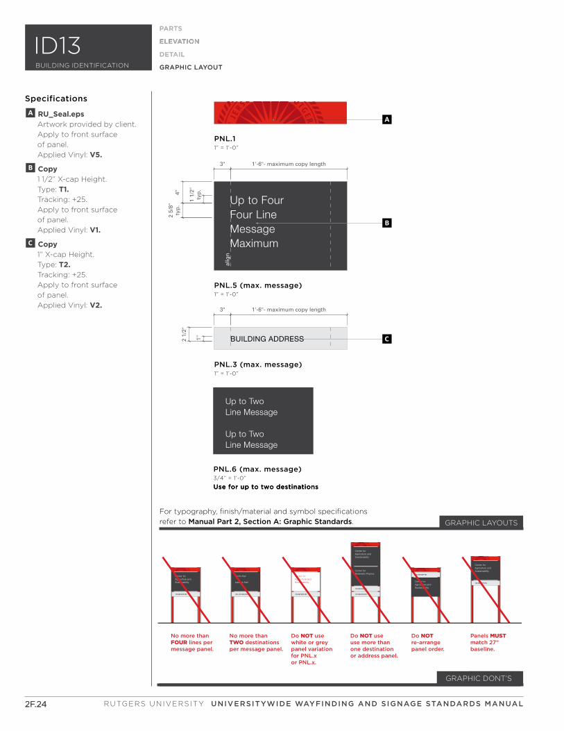
BUILDING ADDRESS
A
B
C
Up to TwoLine Message
Up to Two Line Message
Up to TwoLine Message
Up to Two Line Message
No more than FOUR lines per message panel.
No more than TWO destinationsper message panel.
Panels MUSTmatch 27” baseline.
Do NOT use white or greypanel variation for PNL.x or PNL.x.
Do NOT use use more thanone destination or address panel.
Do NOT re-arrange panel order.
120 BEIVER RD.
Center for Agriculture andSustainability
120-122 BEIVER RD.
Smith Hall
Lawson Hall
120 BEIVER RD.
Center for Agriculture andSustainability
122 BEIVER RD.
120 BEIVER RD.
Center for Agriculture andSustainability
Center for Biokinetic Physics 120 BEIVER RD.
Center for Agriculture andSustainability
120 BEIVER RD.
Center for Agriculture andSustainability
PNL.3 (max. message)1” = 1’-0”
PNL.5 (max. message)1” = 1’-0”
PNL.11” = 1’-0”
PNL.6 (max. message)3/4” = 1’-0”
Use for up to two destinationsUse for up to two destinations
alig
n
3" 1'-6"- maximum copy length
1"2 1/
2"
3" 1'-6"- maximum copy length
4"2
5/8"
typ
.
1 1/
2"ty
p.
MessageMaximum
Up to Four Four Line
2F.24
ELEVATION
PARTS
ELEVATION
DETAIL
GRAPHIC LAYOUT
Specifications
2F.24
PARTS
ELEVATION
DETAIL
GRAPHIC LAYOUT
GRAPHIC DONT’S
For typography, finish/material and symbol specifications
refer to Manual Part 2, Section A: Graphic Standards. GRAPHIC LAYOUTS
A RU_Seal.eps Artwork provided by client.
Apply to front surface
of panel.
Applied Vinyl: V5.
B Copy 1 1/2” X-cap Height.
Type: T1. Tracking: +25.
Apply to front surface
of panel.
Applied Vinyl: V1.
C Copy 1” X-cap Height.
Type: T2. Tracking: +25.
Apply to front surface
of panel.
Applied Vinyl: V2.
z
RUTGERS UNIVERSITY UNIVERSITYWIDE WAYFINDING AND SIGNAGE STANDARDS MANUAL
ID13BUILDING IDENTIFICATION

z
SECTION F:
ID20 SERIES
SUB-SECTION
2F.26
Questions? Please contact xxxxx
?
RUTGERS UNIVERSITY UNIVERSITYWIDE WAYFINDING AND SIGNAGE STANDARDS MANUAL
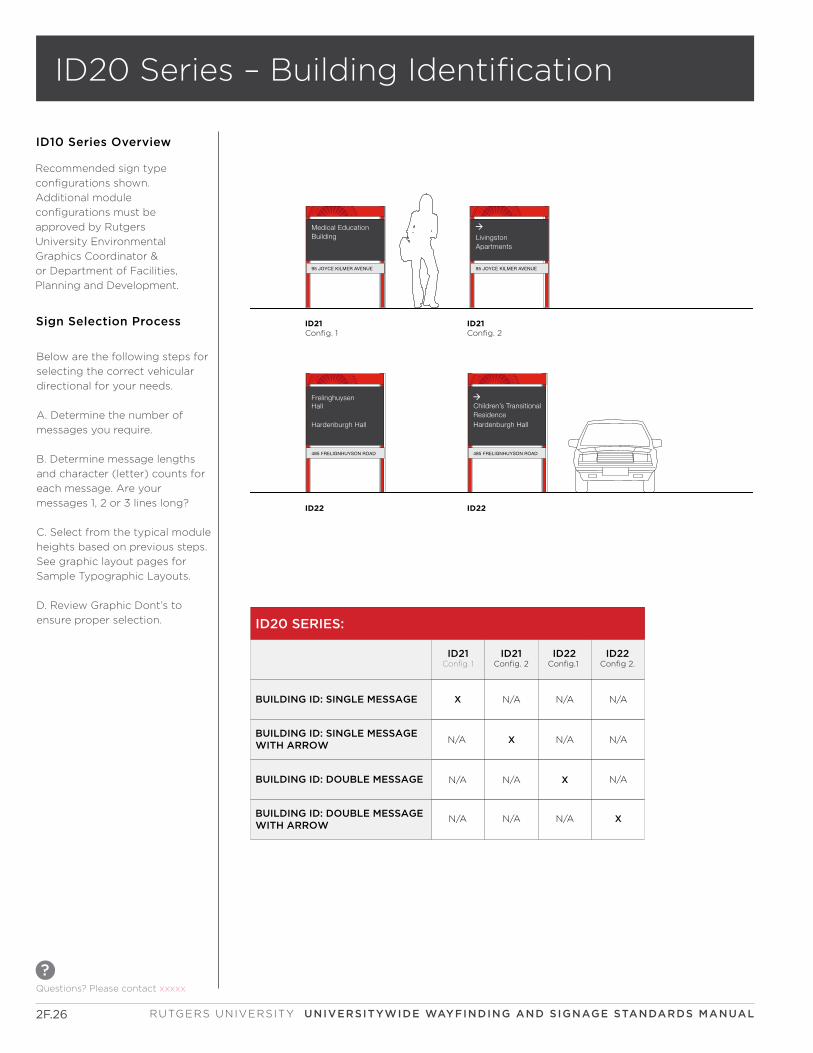
ID10 Series Overview
Recommended sign type
configurations shown.
Additional module
configurations must be
approved by Rutgers
University Environmental
Graphics Coordinator &
or Department of Facilities,
Planning and Development.
LivingstonApartments
Medical Education Building
485 FRELIGNHUYSON ROAD
Children’s TransitionalResidenceHardenburgh Hall
Frelinghuysen Hall
Hardenburgh Hall
485 FRELIGNHUYSON ROAD
Medical Education Building
95 JOYCE KILMER AVENUE
LivingstonApartments
95 JOYCE KILMER AVENUE
ID20 SERIES:
BUILDING ID: SINGLE MESSAGE
BUILDING ID: SINGLE MESSAGE WITH ARROW
BUILDING ID: DOUBLE MESSAGE
ID21Config. 1
ID21Config. 2
N/A
X
X
N/A
N/A
BUILDING ID: DOUBLE MESSAGE WITH ARROW
ID22Config.1
N/A
X
N/A
ID22Config 2.
N/A
N/A
N/A
XN/A
N/A
N/A N/A
Below are the following steps for
selecting the correct vehicular
directional for your needs.
A. Determine the number of
messages you require.
B. Determine message lengths
and character (letter) counts for
each message. Are your
messages 1, 2 or 3 lines long?
C. Select from the typical module
heights based on previous steps.
See graphic layout pages for
Sample Typographic Layouts.
D. Review Graphic Dont’s to
ensure proper selection.
Sign Selection Process
ID20 Series – Building Identification
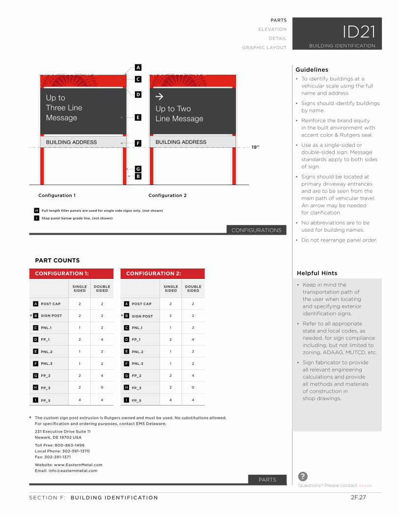
PARTS
Up to Three Line Message
BUILDING ADDRESS BUILDING ADDRESS
Up to TwoLine Message
Configuration 1 Configuration 2
a
C
D
GB
E
F
H
I
Full length filler panels are used for single side signs only. (not shown)
Stop panel below grade line. (not shown)
19’’
PARTS
ELEVATION
DETAIL
GRAPHIC LAYOUT
ID21
PART COUNTS
POST CAP POST CAP
SIGN POST SIGN POST
PNL.1 PNL.1
FP_1 FP_1
PNL.2 PNL.2
PNL.3 PNL.3
FP_2 FP_2
FP_3 FP_3
FP_5 FP_5
2 2
2 2
1 1
2 2
1 1
1 1
2 2
2 2
4 4
2 2
2 2
2 2
4 4
2 2
2 2
4 4
0 0
4 4
CONFIGURATION 1: CONFIGURATION 2:
SINGLE SIDED
SINGLE SIDED
DOUBLE SIDED
DOUBLE SIDED
A A
BB
C C
D D
E E
F F
G G
H H
I I
* *
* The custom sign post extrusion is Rutgers owned and must be used. No substitutions allowed.
For specification and ordering purposes, contact EMS Delaware;
231 Executive Drive Suite 11
Newark, DE 19702 USA
Toll Free: 800-863-1496
Local Phone: 302-391-1370
Fax: 302-391-1371
Website: www.EasternMetal.com
Email: [email protected]
CONFIGURATIONS
Questions? Please contact xxxxx
?
BUILDING IDENTIFICATION
2F.27SECTION F: BUILDING IDENTIFICATION
Helpful Hints
• Keep in mind the
transportation path of
the user when locating
and specifying exterior
identification signs.
• Refer to all appropriate
state and local codes, as
needed, for sign compliance
including, but not limited to
zoning, ADAAG, MUTCD, etc.
• Sign fabricator to provide
all relevant engineering
calculations and provide
all methods and materials
of construction in
shop drawings.
• To identify buildings at a
vehicular scale using the full
name and address.
• Signs should identify buildings
by name.
• Reinforce the brand equity
in the built environment with
accent color & Rutgers seal.
• Use as a single-sided or
double-sided sign. Message
standards apply to both sides
of sign.
• Signs should be located at
primary driveway entrances
and are to be seen from the
main path of vehicular travel.
An arrow may be needed
for clarification.
• No abbreviations are to be
used for building names.
• Do not rearrange panel order.
Guidelines
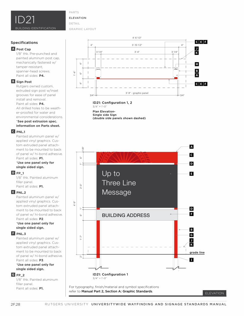
Up to Three Line Message
BUILDING ADDRESS
4"6"
4"
1'-4
"
3/4"3'-9" - graphic panel
3/4"
3 1/4" 3'-4" 3 1/4"
4" 3'-10 1/2" 4"
4'-6 1/2"
2"1'
-7"
6"1"
2'-0
"1"
6"1/
8"
4'-9
"
grade line
ID21: Configuration 1 3/4” = 1’-0”
Plan Elevation-Single side Sign(double side panels shown dashed)
ID21: Configuration 1, 23/4” = 1’-0”
CEF
CEF
BA
H
A
C
BG
D
E
DF
I
JK
JK
2F.28
ELEVATION
PARTS
ELEVATION
DETAIL
GRAPHIC LAYOUT
Specifications
A Post Cap 1/8” thk. Pre-punched and
painted aluminum post cap,
mechanically fastened w/
tamper-resistant,
spanner-head screws.
Paint all sides: P4.
B Sign Post Rutgers owned custom,
extruded sign post w/inset
grooves for ease of panel
install and removal.
Paint all sides: P4. All drilled holes to be weath-
er-proofed for water and
environmental considerations.
*See post extrusion spec. information on Parts sheet.
C PNL.1 Painted aluminum panel w/
applied vinyl graphics. Cus-
tom extruded panel attach-
ment to be mounted to back
of panel w/ hi-bond adhesive.
Paint all sides: P1. *Use one panel only for single sided sign.
D FP_1 1/8” thk. Painted aluminum
filler panel.
Paint all sides: P1.
E PNL.2 Painted aluminum panel w/
applied vinyl graphics. Cus-
tom extruded panel attach-
ment to be mounted to back
of panel w/ hi-bond adhesive.
Paint all sides: P2.
*Use one panel only for single sided sign.
F PNL.3 Painted aluminum panel w/
applied vinyl graphics. Cus-
tom extruded panel attach-
ment to be mounted to back
of panel w/ hi-bond adhesive.
Paint all sides: P3.
*Use one panel only for single sided sign.
G FP_2 1/8” thk. Painted aluminum
filler panel.
Paint all sides: P1. For typography, finish/material and symbol specifications
refer to Manual Part 2, Section A: Graphic Standards.
RUTGERS UNIVERSITY UNIVERSITYWIDE WAYFINDING AND SIGNAGE STANDARDS MANUAL
ID21BUILDING IDENTIFICATION
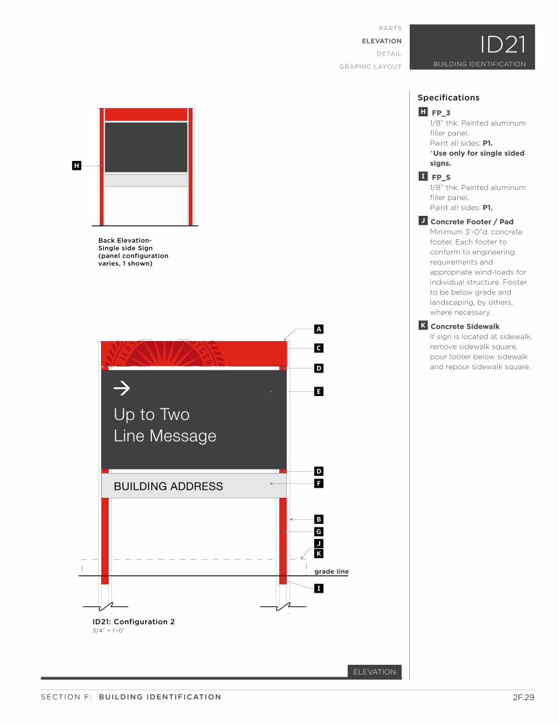
BUILDING ADDRESS
Up to TwoLine Message
grade line
ID21: Configuration 23/4” = 1’-0”
Back Elevation- Single side Sign(panel configurationvaries, 1 shown)
A
C
BG
D
E
DF
I
JK
H
2F.29
ELEVATION
PARTS
ELEVATION
DETAIL
GRAPHIC LAYOUT
Specifications
H FP_3 1/8” thk. Painted aluminum
filler panel.
Paint all sides: P1. *Use only for single sided signs.
I FP_S 1/8” thk. Painted aluminum
filler panel.
Paint all sides: P1.
J Concrete Footer / Pad Minimum 3’-0”d. concrete
footer. Each footer to
conform to engineering
requirements and
appropriate wind-loads for
individual structure. Footer
to be below grade and
landscaping, by others,
where necessary.
K Concrete Sidewalk If sign is located at sidewalk,
remove sidewalk square,
pour footer below sidewalk
and repour sidewalk square.
SECTION F: BUILDING IDENTIFICATION
ID21BUILDING IDENTIFICATION
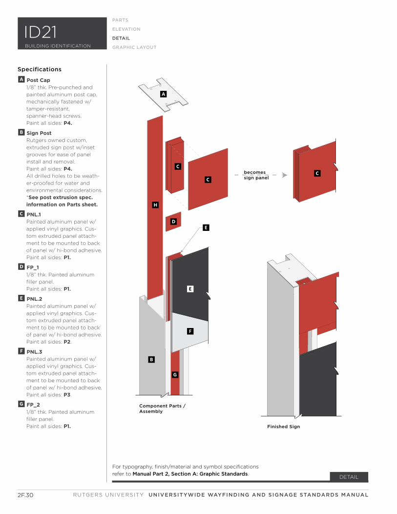
becomessign panel
Component Parts /Assembly
Finished Sign
C
A
C
D
B
G
H
C
E
F
E
2F.30
DETAIL
Specifications
RUTGERS UNIVERSITY UNIVERSITYWIDE WAYFINDING AND SIGNAGE STANDARDS MANUAL
PARTS
ELEVATION
DETAIL
GRAPHIC LAYOUT
A Post Cap 1/8” thk. Pre-punched and
painted aluminum post cap,
mechanically fastened w/
tamper-resistant,
spanner-head screws.
Paint all sides: P4.
B Sign Post Rutgers owned custom,
extruded sign post w/inset
grooves for ease of panel
install and removal.
Paint all sides: P4. All drilled holes to be weath-
er-proofed for water and
environmental considerations.
*See post extrusion spec. information on Parts sheet.
C PNL.1 Painted aluminum panel w/
applied vinyl graphics. Cus-
tom extruded panel attach-
ment to be mounted to back
of panel w/ hi-bond adhesive.
Paint all sides: P1.
D FP_1 1/8” thk. Painted aluminum
filler panel.
Paint all sides: P1.
E PNL.2 Painted aluminum panel w/
applied vinyl graphics. Cus-
tom extruded panel attach-
ment to be mounted to back
of panel w/ hi-bond adhesive.
Paint all sides: P2.
F PNL.3 Painted aluminum panel w/
applied vinyl graphics. Cus-
tom extruded panel attach-
ment to be mounted to back
of panel w/ hi-bond adhesive.
Paint all sides: P3.
G FP_2 1/8” thk. Painted aluminum
filler panel.
Paint all sides: P1.
ID21BUILDING IDENTIFICATION
For typography, finish/material and symbol specifications
refer to Manual Part 2, Section A: Graphic Standards.
3'-2" panel length
3/4" 1 3/4" 3/4"
3 1/4"
1/8"
typ
.
7/8"
4 1/
4"7/
8"
6"
1/8"7/8"
1/8"
1 1/8"
1/4"
pan
el e
xtru
sio
n v
arie
s-se
e el
evat
ion
s fo
r h
eig
ht
dim
ensi
on
s
1/4"
pan
el h
eig
ht
vari
es-
see
elev
atio
ns
for
hei
gh
t d
imen
sio
ns
4" a
bov
e fi
nis
hed
gra
de
1/8"typ.
2"
Partial Horizontal Section 6” = 1’-0”
Vertical Section: Concrete Footerno scale
Plan Elevation at Sidewalkno scale
Panel Detail no scale
fg
B
grade line grade line
B
K
L
M
J
b
K
L
at concrete sidewalk condition
Vertical Section: Concrete Footerno scale
at earth / grass condition
EC
CE
2F.31
DETAIL
Specifications
SECTION F: BUILDING IDENTIFICATION
PARTS
ELEVATION
DETAIL
GRAPHIC LAYOUT
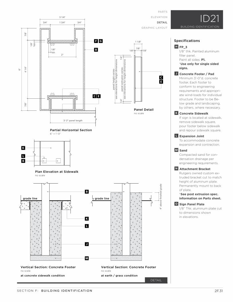
H FP_3 1/8” thk. Painted aluminum
filler panel.
Paint all sides: P1. *Use only for single sided signs.
J Concrete Footer / Pad Minimum 3’-0”d. concrete
footer. Each footer to
conform to engineering
requirements and appropri-
ate wind-loads for individual
structure. Footer to be Be-
low grade and landscaping,
by others, where necessary.
K Concrete Sidewalk If sign is located at sidewalk,
remove sidewalk square,
pour footer below sidewalk
and repour sidewalk square.
L Expansion Joint To accommodate concrete
expansion and contraction.
M Sand Compacted sand for con-
densation drainage per
engineering requirements.
N Attachment Bracket Rutgers owned custom ex-
truded bracket cut to match
height of aluminum plate.
Permanently mount to back
of plate.
*See post extrusion spec. information on Parts sheet.
O Sign Panel Plate 1/8” Thk. aluminum plate cut
to dimensions shown
in elevations.
ID21BUILDING IDENTIFICATION
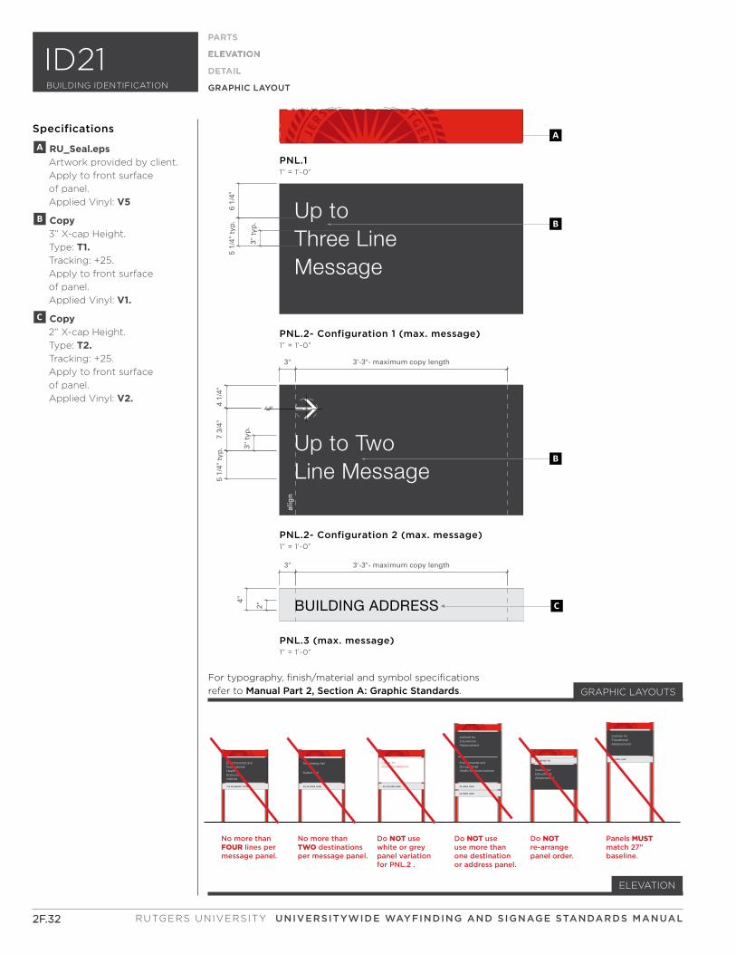
No more than FOUR lines per message panel.
No more than TWO destinationsper message panel.
Panels MUSTmatch 27” baseline.
Do NOT use white or greypanel variation for PNL.2 .
Do NOT use use more thanone destination or address panel.
Do NOT re-arrange panel order.
123 MULBERRY STREET
HealthSciencesInstitute
Environmental andOccupational
40-44 HOES LANE
225 BEIVER RD.
40 HOES LANE
42 HOES LANE
40 HOES LANE
Trenchberg Hall
Sutton Hall
40-44 HOES LANE
Center for Advanced Medicine
Health Sciences Institute
Environmental andOccupational
Advancement
Institute for Educational
Advancement
Institute for Educational
Advancement
Institute for Educational
A
B
C
PNL.3 (max. message)1” = 1’-0”
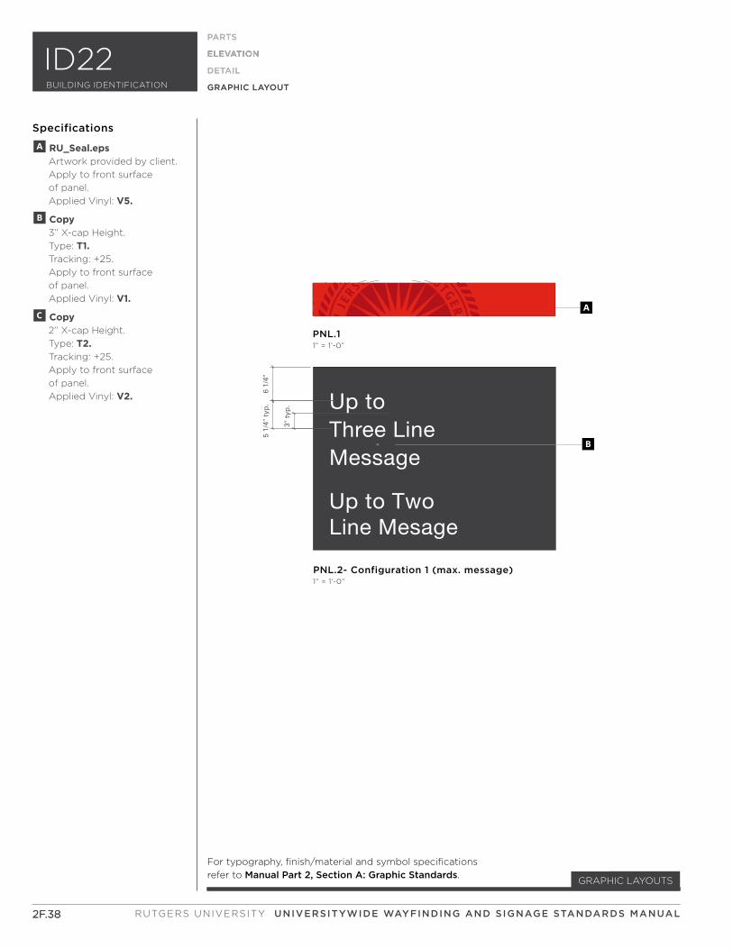
PNL.2- Configuration 2 (max. message)1” = 1’-0”
PNL.11” = 1’-0”
alig
n
B
PNL.2- Configuration 1 (max. message)1” = 1’-0”
3" 3'-3"- maximum copy length
3" 3'-3"- maximum copy length
2"
4"
C L
4 1/
4"7
3/4"
5 1/
4" t
yp. 3"
typ
.3"
typ
.
6 1/
4"5
1/4"
typ
.
2F.32
ELEVATION
PARTS
ELEVATION
DETAIL
GRAPHIC LAYOUT
Specifications
2F.32
PARTS
ELEVATION
DETAIL
GRAPHIC LAYOUT
For typography, finish/material and symbol specifications
refer to Manual Part 2, Section A: Graphic Standards. GRAPHIC LAYOUTS
A RU_Seal.eps Artwork provided by client.
Apply to front surface
of panel.
Applied Vinyl: V5
B Copy 3” X-cap Height.
Type: T1. Tracking: +25.
Apply to front surface
of panel.
Applied Vinyl: V1.
C Copy 2” X-cap Height.
Type: T2. Tracking: +25.
Apply to front surface
of panel.
Applied Vinyl: V2.
RUTGERS UNIVERSITY UNIVERSITYWIDE WAYFINDING AND SIGNAGE STANDARDS MANUAL
ID21BUILDING IDENTIFICATION
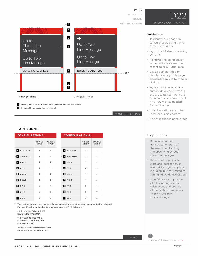
Up to TwoLine Mesage
BUILDING ADDRESS
Up toThree LineMessage
BUILDING ADDRESS
Up to TwoLine Message
Up to TwoLine Mesage
Configuration 1 Configuration 2
a
D
GB
E
F
H
I
Full length filler panels are used for single side signs only. (not shown)
Stop panel below grade line. (not shown)
19’’
C
PARTS
ELEVATION
DETAIL
GRAPHIC LAYOUT
ID22
PART COUNTS
POST CAP
SIGN POST
PNL.1
FP_1
PNL.2
PNL.3
FP_2
FP_3
FP_5
2
2
1
2
1
1
2
2
4
2
2
2
4
2
2
4
0
4
CONFIGURATION 1:
SINGLE SIDED
DOUBLE SIDED
A
B
C
D
E
F
G
H
I
*
* The custom sign post extrusion is Rutgers owned and must be used. No substitutions allowed.
For specification and ordering purposes, contact EMS Delaware;
231 Executive Drive Suite 11
Newark, DE 19702 USA
Toll Free: 800-863-1496
Local Phone: 302-391-1370
Fax: 302-391-1371
Website: www.EasternMetal.com
Email: [email protected]
CONFIGURATIONS
Questions? Please contact xxxxx
?
BUILDING IDENTIFICATION
PARTS
POST CAP
SIGN POST
PNL.1
FP_1
PNL.2
PNL.3
FP_2
FP_3
FP_5
2
2
1
2
1
1
2
2
4
2
2
2
4
2
2
4
0
4
CONFIGURATION 2:
SINGLE SIDED
DOUBLE SIDED
A
B
C
D
E
F
G
H
I
*
2F.33SECTION F: BUILDING IDENTIFICATIONSECTION F: BUILDING IDENTIFICATION
Helpful Hints
• Keep in mind the
transportation path of
the user when locating
and specifying exterior
identification signs.
• Refer to all appropriate
state and local codes, as
needed, for sign compliance
including, but not limited to
zoning, ADAAG, MUTCD, etc.
• Sign fabricator to provide
all relevant engineering
calculations and provide
all methods and materials
of construction in
shop drawings.
• To identify buildings at a
vehicular scale using the full
name and address.
• Signs should identify buildings
by name.
• Reinforce the brand equity
in the built environment with
accent color & Rutgers seal.
• Use as a single-sided or
double-sided sign. Message
standards apply to both sides
of sign.
• Signs should be located at
primary driveway entrances
and are to be seen from the
main path of vehicular travel.
An arrow may be needed
for clarification.
• No abbreviations are to be
used for building names.
• Do not rearrange panel order.
Guidelines
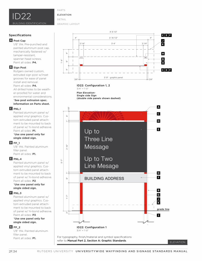
Up to TwoLine Mesage
BUILDING ADDRESS
Up toThree LineMessage
4"6"
4"
1'-4
"
3/4"3'-9" - graphic panel
3/4"
3 1/4" 3'-4" 3 1/4"
4" 3'-10 1/2" 4"
4'-6 1/2"
2"1'
-7"
6"1"
2'-1
0"1"
6"1/
8"
5'-7
"
grade line
CEF
CEF
BA
H
ID22: Configuration 1 3/4” = 1’-0”
Plan Elevation-Single side Sign(double side panels shown dashed)
ID22: Configuration 1, 23/4” = 1’-0”
BG
D
E
DF
I
JK
JK
A
C
2F.34
ELEVATION
PARTS
ELEVATION
DETAIL
GRAPHIC LAYOUT
Specifications
A Post Cap 1/8” thk. Pre-punched and
painted aluminum post cap,
mechanically fastened w/
tamper-resistant,
spanner-head screws.
Paint all sides: P4.
B Sign Post Rutgers owned custom,
extruded sign post w/inset
grooves for ease of panel
install and removal.
Paint all sides: P4. All drilled holes to be weath-
er-proofed for water and
environmental considerations.
*See post extrusion spec. information on Parts sheet.
C PNL.1 Painted aluminum panel w/
applied vinyl graphics. Cus-
tom extruded panel attach-
ment to be mounted to back
of panel w/ hi-bond adhesive.
Paint all sides: P1. *Use one panel only for single sided sign.
D FP_1 1/8” thk. Painted aluminum
filler panel.
Paint all sides: P1.
E PNL.4 Painted aluminum panel w/
applied vinyl graphics. Cus-
tom extruded panel attach-
ment to be mounted to back
of panel w/ hi-bond adhesive.
Paint all sides: P2.
*Use one panel only for single sided sign.
F PNL.3 Painted aluminum panel w/
applied vinyl graphics. Cus-
tom extruded panel attach-
ment to be mounted to back
of panel w/ hi-bond adhesive.
Paint all sides: P3.
*Use one panel only for single sided sign.
G FP_2 1/8” thk. Painted aluminum
filler panel.
Paint all sides: P1. For typography, finish/material and symbol specifications
refer to Manual Part 2, Section A: Graphic Standards.
RUTGERS UNIVERSITY UNIVERSITYWIDE WAYFINDING AND SIGNAGE STANDARDS MANUAL
ID22BUILDING IDENTIFICATION
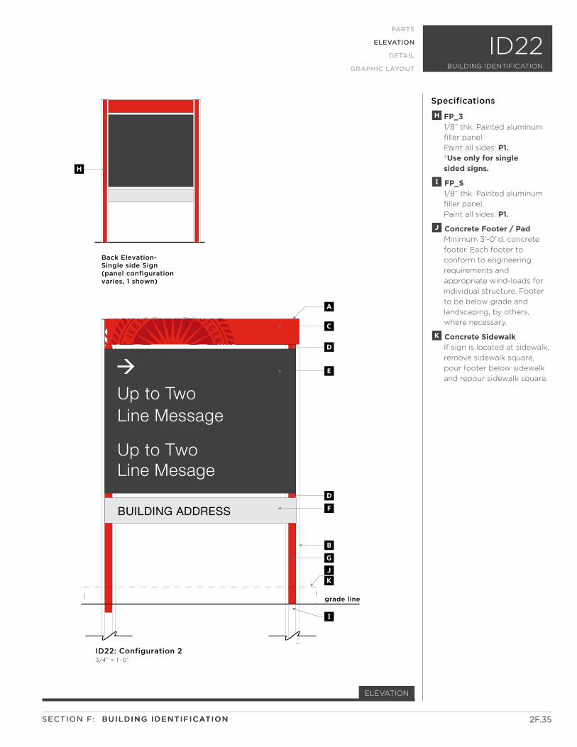
BUILDING ADDRESS
Up to TwoLine Message
Up to TwoLine Mesage
grade line
ID22: Configuration 2 3/4” = 1’-0”
BG
D
E
DF
I
JK
Back Elevation- Single side Sign(panel configurationvaries, 1 shown)
H
A
C
2F.35
ELEVATION
PARTS
ELEVATION
DETAIL
GRAPHIC LAYOUT
Specifications
H FP_3 1/8” thk. Painted aluminum
filler panel.
Paint all sides: P1. *Use only for single sided signs.
I FP_S 1/8” thk. Painted aluminum
filler panel.
Paint all sides: P1.
J Concrete Footer / Pad Minimum 3’-0”d. concrete
footer. Each footer to
conform to engineering
requirements and
appropriate wind-loads for
individual structure. Footer
to be below grade and
landscaping, by others,
where necessary.
K Concrete Sidewalk If sign is located at sidewalk,
remove sidewalk square,
pour footer below sidewalk
and repour sidewalk square.
SECTION F: BUILDING IDENTIFICATIONSECTION F: BUILDING IDENTIFICATION
ID22BUILDING IDENTIFICATION
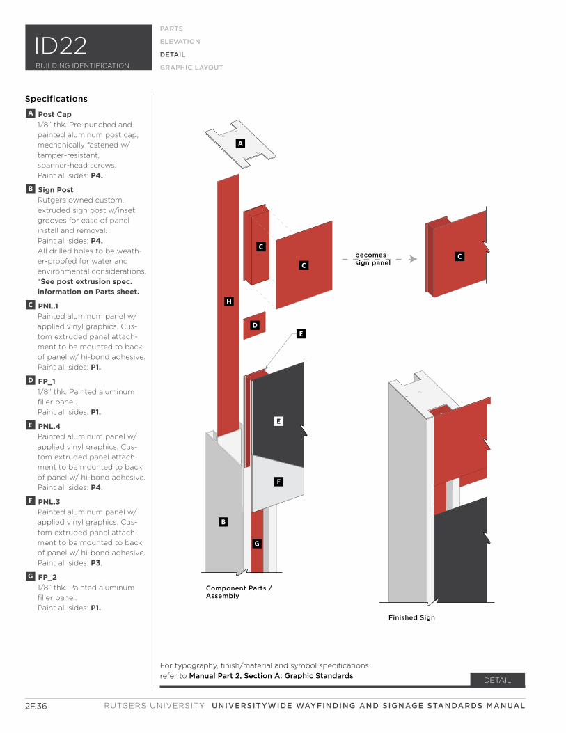
becomessign panel
Component Parts /Assembly
Finished Sign
C
A
C
D
B
G
H
C
E
F
E
2F.36
DETAIL
Specifications
RUTGERS UNIVERSITY UNIVERSITYWIDE WAYFINDING AND SIGNAGE STANDARDS MANUAL
PARTS
ELEVATION
DETAIL
GRAPHIC LAYOUT
A Post Cap 1/8” thk. Pre-punched and
painted aluminum post cap,
mechanically fastened w/
tamper-resistant,
spanner-head screws.
Paint all sides: P4.
B Sign Post Rutgers owned custom,
extruded sign post w/inset
grooves for ease of panel
install and removal.
Paint all sides: P4. All drilled holes to be weath-
er-proofed for water and
environmental considerations.
*See post extrusion spec. information on Parts sheet.
C PNL.1 Painted aluminum panel w/
applied vinyl graphics. Cus-
tom extruded panel attach-
ment to be mounted to back
of panel w/ hi-bond adhesive.
Paint all sides: P1.
D FP_1 1/8” thk. Painted aluminum
filler panel.
Paint all sides: P1.
E PNL.4 Painted aluminum panel w/
applied vinyl graphics. Cus-
tom extruded panel attach-
ment to be mounted to back
of panel w/ hi-bond adhesive.
Paint all sides: P4.
F PNL.3 Painted aluminum panel w/
applied vinyl graphics. Cus-
tom extruded panel attach-
ment to be mounted to back
of panel w/ hi-bond adhesive.
Paint all sides: P3.
G FP_2 1/8” thk. Painted aluminum
filler panel.
Paint all sides: P1.
ID22BUILDING IDENTIFICATION
For typography, finish/material and symbol specifications
refer to Manual Part 2, Section A: Graphic Standards.
3'-2" panel length
3/4" 1 3/4" 3/4"
3 1/4"
1/8"
typ
.
7/8"
4 1/
4"7/
8"
6"
1/8"7/8"
1/8"
1 1/8"
1/4"
pan
el e
xtru
sio
n v
arie
s-se
e el
evat
ion
s fo
r h
eig
ht
dim
ensi
on
s
1/4"
pan
el h
eig
ht
vari
es-
see
elev
atio
ns
for
hei
gh
t d
imen
sio
ns
4" a
bov
e fi
nis
hed
gra
de
1/8"typ.
2"
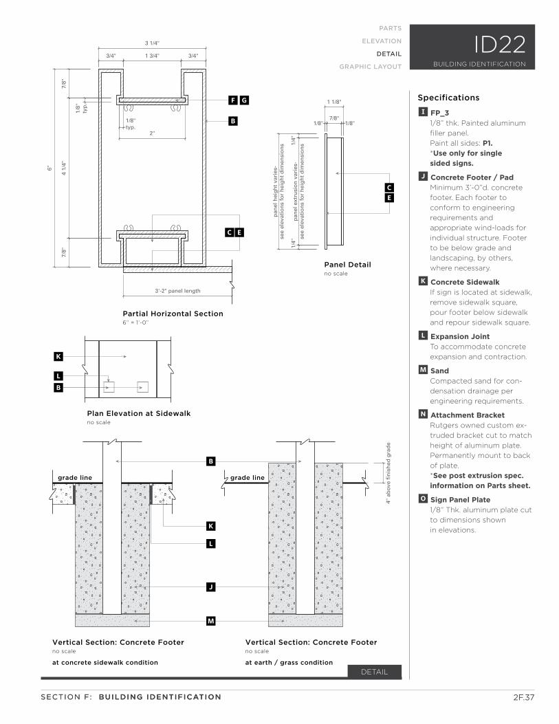
Partial Horizontal Section 6” = 1’-0”
Vertical Section: Concrete Footerno scale
Plan Elevation at Sidewalkno scale
Panel Detail no scale
fg
B
grade line grade line
B
K
L
M
J
b
K
L
at concrete sidewalk condition
Vertical Section: Concrete Footerno scale
at earth / grass condition
EC
CE
2F.37
DETAIL
SECTION F: BUILDING IDENTIFICATION
Specifications
SECTION F: BUILDING IDENTIFICATION
PARTS
ELEVATION
DETAIL
GRAPHIC LAYOUT
I FP_3 1/8” thk. Painted aluminum
filler panel.
Paint all sides: P1. *Use only for single sided signs.
J Concrete Footer / Pad Minimum 3’-0”d. concrete
footer. Each footer to
conform to engineering
requirements and
appropriate wind-loads for
individual structure. Footer
to be below grade and
landscaping, by others,
where necessary.
K Concrete Sidewalk If sign is located at sidewalk,
remove sidewalk square,
pour footer below sidewalk
and repour sidewalk square.
L Expansion Joint To accommodate concrete
expansion and contraction.
M Sand Compacted sand for con-
densation drainage per
engineering requirements.
N Attachment Bracket Rutgers owned custom ex-
truded bracket cut to match
height of aluminum plate.
Permanently mount to back
of plate.
*See post extrusion spec. information on Parts sheet.
O Sign Panel Plate 1/8” Thk. aluminum plate cut
to dimensions shown
in elevations.
ID22BUILDING IDENTIFICATION
Up to TwoLine Mesage
Up toThree LineMessage
A
PNL.11” = 1’-0”
B
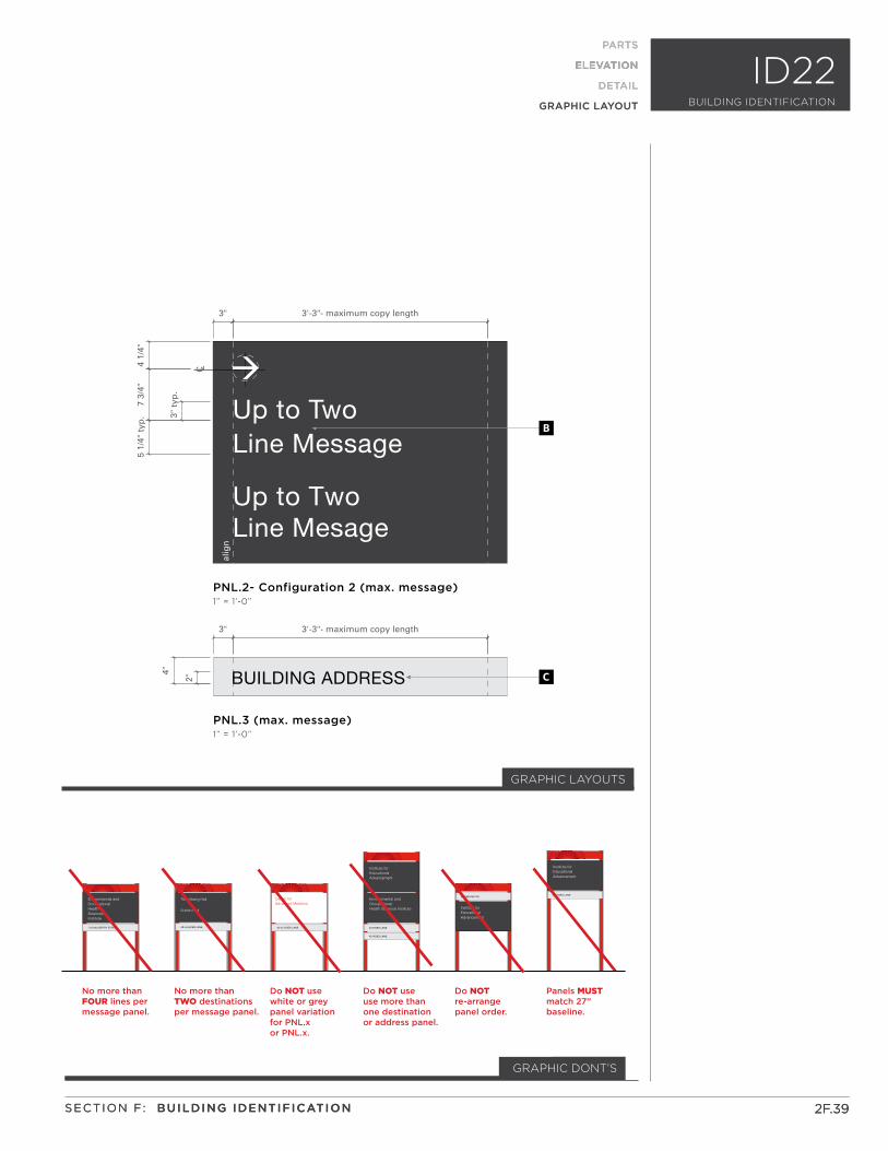
PNL.2- Configuration 1 (max. message)1” = 1’-0”
3" t
yp.
6 1/
4"5
1/4"
typ
.
2F.38
ELEVATION
PARTS
ELEVATION
DETAIL
GRAPHIC LAYOUT
Specifications
For typography, finish/material and symbol specifications
refer to Manual Part 2, Section A: Graphic Standards.
2F.38
PARTS
ELEVATION
DETAIL
GRAPHIC LAYOUT
GRAPHIC LAYOUTS
A RU_Seal.eps Artwork provided by client.
Apply to front surface
of panel.
Applied Vinyl: V5.
B Copy 3” X-cap Height.
Type: T1. Tracking: +25.
Apply to front surface
of panel.
Applied Vinyl: V1.
C Copy 2” X-cap Height.
Type: T2. Tracking: +25.
Apply to front surface
of panel.
Applied Vinyl: V2.
RUTGERS UNIVERSITY UNIVERSITYWIDE WAYFINDING AND SIGNAGE STANDARDS MANUAL
ID22BUILDING IDENTIFICATION
Up to TwoLine Message
Up to TwoLine Mesage
No more than FOUR lines per message panel.
No more than TWO destinationsper message panel.
Panels MUSTmatch 27” baseline.
Do NOT use white or greypanel variation for PNL.x or PNL.x.
Do NOT use use more thanone destination or address panel.
Do NOT re-arrange panel order.
123 MULBERRY STREET
HealthSciencesInstitute
Environmental andOccupational
40-44 HOES LANE
225 BEIVER RD.
40 HOES LANE
42 HOES LANE
40 HOES LANE
Trenchberg Hall
Sutton Hall
40-44 HOES LANE
Center for Advanced Medicine
Health Sciences Institute
Environmental andOccupational
Advancement
Institute for Educational
Advancement
Institute for Educational
Advancement
Institute for Educational
B
C
PNL.3 (max. message)1” = 1’-0”
PNL.2- Configuration 2 (max. message)1” = 1’-0”
alig
n
3" 3'-3"- maximum copy length
2"
4"
3" 3'-3"- maximum copy length
C L
4 1/
4"7
3/4"
5 1/
4" t
yp. 3"
typ
.
2F.39
ELEVATION
PARTS
ELEVATION
DETAIL
GRAPHIC LAYOUT
Specifications
2F.39
PARTS
ELEVATION
DETAIL
GRAPHIC LAYOUT
GRAPHIC DONT’S
GRAPHIC LAYOUTS
SECTION F: BUILDING IDENTIFICATIONSECTION F: BUILDING IDENTIFICATION
ID22BUILDING IDENTIFICATION

2F.40 RUTGERS UNIVERSITY SIGNAGE STANDARDS MANUAL
This Page Intentionally Left Blank
SUB-SECTION
SECTION F:
ID30 SERIES
Questions? Please contact xxxxx
?
2F.42 RUTGERS UNIVERSITY UNIVERSITYWIDE WAYFINDING AND SIGNAGE STANDARDS MANUAL
ID30 Series – Building Identification
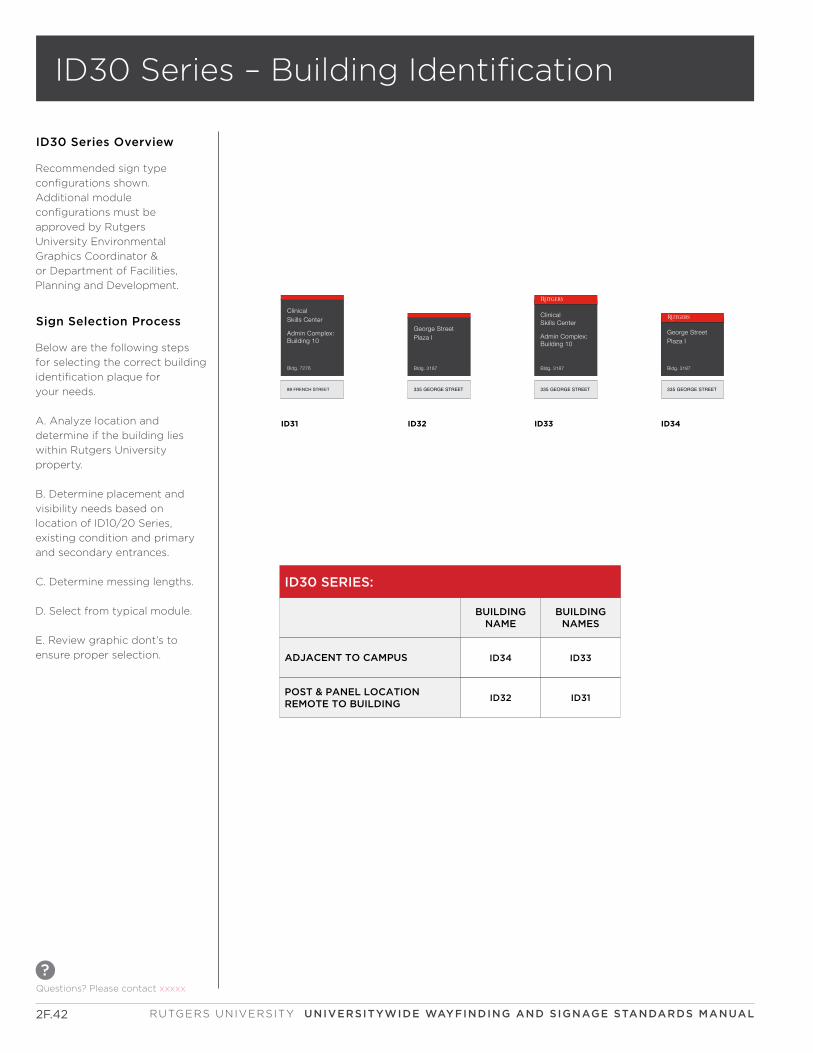
ID30 Series Overview
Recommended sign type
configurations shown.
Additional module
configurations must be
approved by Rutgers
University Environmental
Graphics Coordinator &
or Department of Facilities,
Planning and Development.
ID32 ID33 ID34ID31
Bldg. 3187
335 GEORGE STREET
George StreetPlaza I
Bldg. 3187
335 GEORGE STREET
George StreetPlaza I
Bldg. 3187
335 GEORGE STREET
Skills CenterClinical
Admin Complex:Building 10
ClinicalSkills Center
Admin Complex:Building 10
Bldg. 7276
89 FRENCH STREET
ID30 SERIES:
ADJACENT TO CAMPUS
POST & PANEL LOCATIONREMOTE TO BUILDING
BUILDINGNAME
BUILDINGNAMES
ID34 ID33
ID31ID32
Below are the following steps
for selecting the correct building
identification plaque for
your needs.
A. Analyze location and
determine if the building lies
within Rutgers University
property.
B. Determine placement and
visibility needs based on
location of ID10/20 Series,
existing condition and primary
and secondary entrances.
C. Determine messing lengths.
D. Select from typical module.
E. Review graphic dont’s to
ensure proper selection.
Sign Selection Process
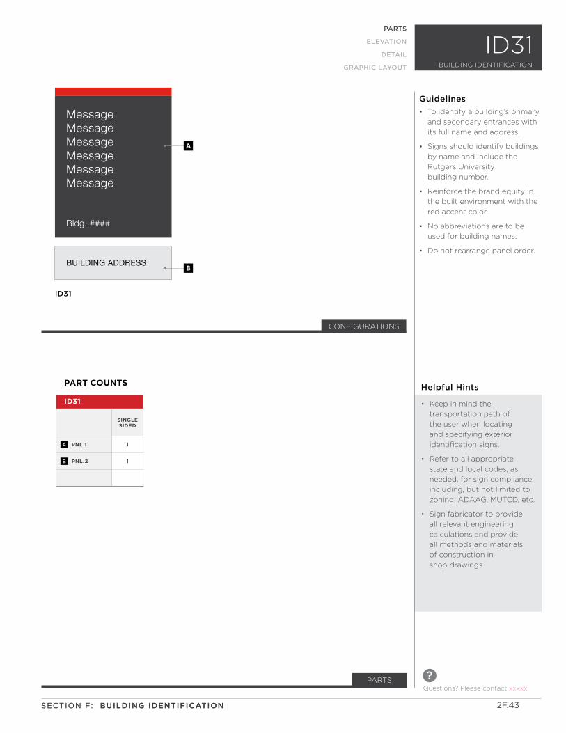
MessageMessageMessageMessageMessageMessage
Bldg. ####
BUILDING ADDRESS
ID31
B
A
CONFIGURATIONS
PNL.1
PNL.2
1
1
ID31
PART COUNTS
SINGLE SIDED
A
B
Helpful Hints
• Keep in mind the
transportation path of
the user when locating
and specifying exterior
identification signs.
• Refer to all appropriate
state and local codes, as
needed, for sign compliance
including, but not limited to
zoning, ADAAG, MUTCD, etc.
• Sign fabricator to provide
all relevant engineering
calculations and provide
all methods and materials
of construction in
shop drawings.
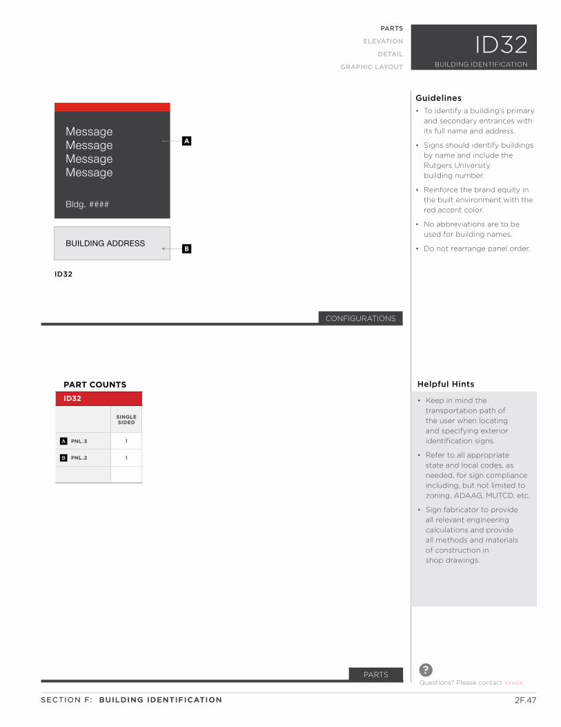
• To identify a building’s primary
and secondary entrances with
its full name and address.
• Signs should identify buildings
by name and include the
Rutgers University
building number.
• Reinforce the brand equity in
the built environment with the
red accent color.
• No abbreviations are to be
used for building names.
• Do not rearrange panel order.
Guidelines
Questions? Please contact xxxxx
?PARTS
2F.43SECTION F: BUILDING IDENTIFICATIONSECTION F: BUILDING IDENTIFICATION
ID31BUILDING IDENTIFICATION
PARTS
ELEVATION
DETAIL
GRAPHIC LAYOUT
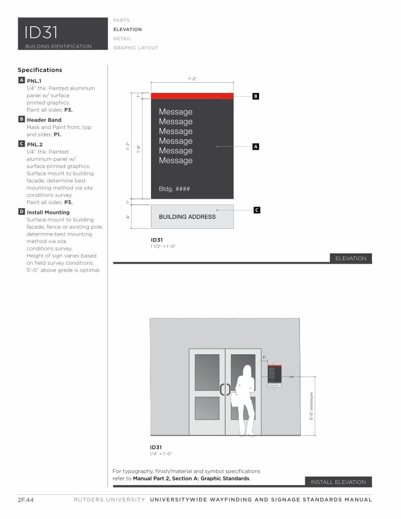
MessageMessageMessageMessageMessageMessage
Bldg. ####
BUILDING ADDRESS
C L
Park ing Only
Univers i ty Hang Tag Required
Unauthor ized Vehic les Wi l l be T icketed and Towed
5'-0
" m
inim
um
6"
MessageMessageMessageMessageMessageMessage
Bldg. ####
BUILDING ADDRESS
1'-2"
1"1'
-6"
1'-7
"1"
4"
A
B
C
ID311 1/2” = 1’-0”
ID311/4” = 1’-0”
2F.44
ELEVATION
PARTS
ELEVATION
DETAIL
GRAPHIC LAYOUT
Specifications
For typography, finish/material and symbol specifications
refer to Manual Part 2, Section A: Graphic Standards.
ELEVATION
INSTALL ELEVATION
A PNL.1 1/4” thk. Painted aluminum
panel w/ surface
printed graphics.
Paint all sides: P3.
B Header Band Mask and Paint front, top
and sides: P1.
C PNL.2 1/4” thk. Painted
aluminum panel w/
surface printed graphics.
Surface mount to building
facade; determine best
mounting method via site
conditions survey.
Paint all sides: P3.
D Install Mounting Surface mount to building
facade, fence or existing pole;
determine best mounting
method via site
conditions survey.
Height of sign varies based
on field survey conditions.
5’-0” above grade is optimal.
RUTGERS UNIVERSITY UNIVERSITYWIDE WAYFINDING AND SIGNAGE STANDARDS MANUAL
BUILDING IDENTIFICATION
ID31
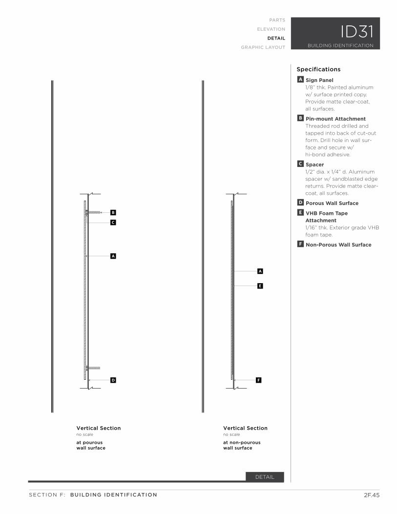
Vertical Sectionno scale
at pourous wall surface
Vertical Sectionno scale
at non-pourous wall surface
B
C
A
E
A
D F
2F.45
PARTS
ELEVATION
DETAIL
GRAPHIC LAYOUT
DETAIL
Specifications
A Sign Panel 1/8” thk. Painted aluminum
w/ surface printed copy.
Provide matte clear-coat,
all surfaces.
B Pin-mount Attachment Threaded rod drilled and
tapped into back of cut-out
form. Drill hole in wall sur-
face and secure w/
hi-bond adhesive.
C Spacer 1/2” dia. x 1/4” d. Aluminum
spacer w/ sandblasted edge
returns. Provide matte clear-
coat, all surfaces.
D Porous Wall Surface
E VHB Foam Tape Attachment 1/16” thk. Exterior grade VHB
foam tape.
F Non-Porous Wall Surface
SECTION F: BUILDING IDENTIFICATION
ID31BUILDING IDENTIFICATION
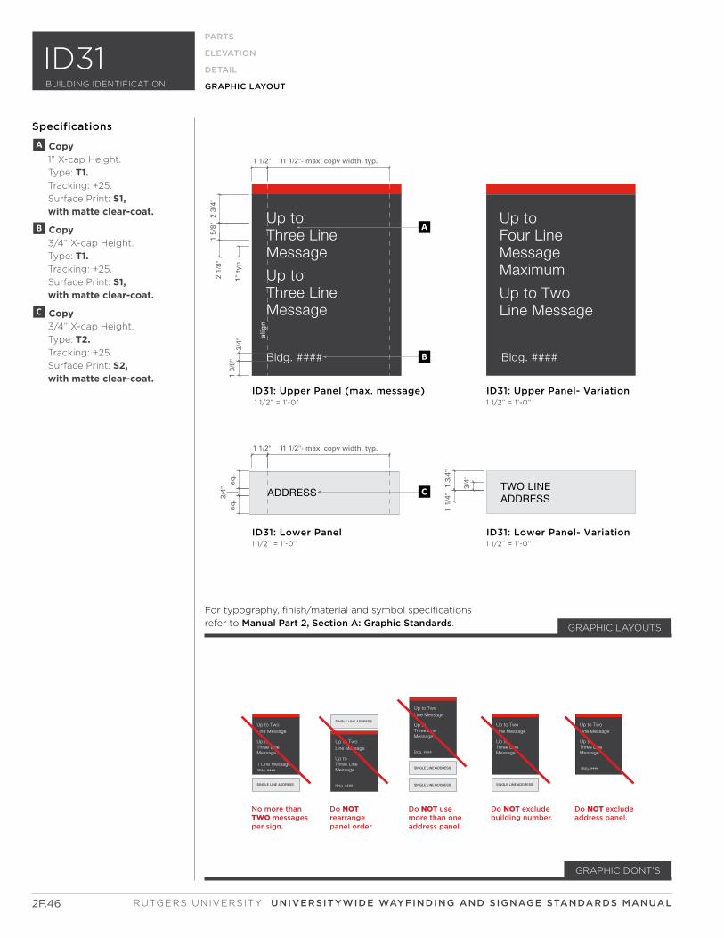
Up to TwoLine Message
Up toThree LineMessage
Bldg. ####
SINGLE LINE ADDRESS
Up to TwoLine Message
Up toThree LineMessage
Bldg. ####
SINGLE LINE ADDRESS
SINGLE LINE ADDRESS
Up to TwoLine Message
Up toThree LineMessage
SINGLE LINE ADDRESS
Up to TwoLine Message
Up toThree LineMessage
Up to TwoLine Message
1 Line Message
Up toThree LineMessage
SINGLE LINE ADDRESS
Bldg. ####Bldg. ####
Do NOTrearrange panel order
Do NOT use more than one address panel.
Do NOT exclude building number.
Do NOT exclude address panel.
No more than TWO messages per sign.
1 1/2" 11 1/2"- max. copy width, typ.
1 1/2" 11 1/2"- max. copy width, typ.
1" t
yp.
1 3/
8"3/
4"eq
.3/
4"eq
.
3/4"
2 3/
4"1
5/8"
2 1/
8"
1 3/
4"1
1/4"
alig
n
ID31: Lower Panel1 1/2” = 1’-0”
ID31: Upper Panel (max. message) 1 1/2” = 1’-0”
ID31: Lower Panel- Variation1 1/2” = 1’-0”
ID31: Upper Panel- Variation1 1/2” = 1’-0”
A
B
C
GRAPHIC LAYOUTS
RUTGERS UNIVERSITY UNIVERSITYWIDE WAYFINDING AND SIGNAGE STANDARDS MANUAL
PARTS
ELEVATION
DETAIL
GRAPHIC LAYOUT
2F.46
BUILDING IDENTIFICATION
ID31
For typography, finish/material and symbol specifications
refer to Manual Part 2, Section A: Graphic Standards.
GRAPHIC DONT’S
Specifications
A Copy 1” X-cap Height.
Type: T1. Tracking: +25.
Surface Print: S1, with matte clear-coat.
B Copy 3/4” X-cap Height.
Type: T1. Tracking: +25.
Surface Print: S1, with matte clear-coat.
C Copy 3/4” X-cap Height.
Type: T2. Tracking: +25.
Surface Print: S2, with matte clear-coat.
Up to Three Line Message
BUILDING ADDRESS BUILDING ADDRESS
Up to TwoLine Message
Configuration 1 Configuration 2
a
C
D
GB
E
F
H
I
Full length filler panels are used for single side signs only. (not shown)
Stop panel below grade line. (not shown)
19’’
MessageMessageMessageMessage
Bldg. ####
BUILDING ADDRESS
ID32
B
A
CONFIGURATIONS
PNL.3
PNL.2
1
1
ID32
PART COUNTS
SINGLE SIDED
A
B
ID32PARTS
ELEVATION
DETAIL
GRAPHIC LAYOUT
Helpful Hints
• Keep in mind the
transportation path of
the user when locating
and specifying exterior
identification signs.
• Refer to all appropriate
state and local codes, as
needed, for sign compliance
including, but not limited to
zoning, ADAAG, MUTCD, etc.
• Sign fabricator to provide
all relevant engineering
calculations and provide
all methods and materials
of construction in
shop drawings.
• To identify a building’s primary
and secondary entrances with
its full name and address.
• Signs should identify buildings
by name and include the
Rutgers University
building number.
• Reinforce the brand equity in
the built environment with the
red accent color.
• No abbreviations are to be
used for building names.
• Do not rearrange panel order.
Guidelines
2F.47
Questions? Please contact xxxxx
?PARTS
SECTION F: BUILDING IDENTIFICATIONSECTION F: BUILDING IDENTIFICATION
BUILDING IDENTIFICATION
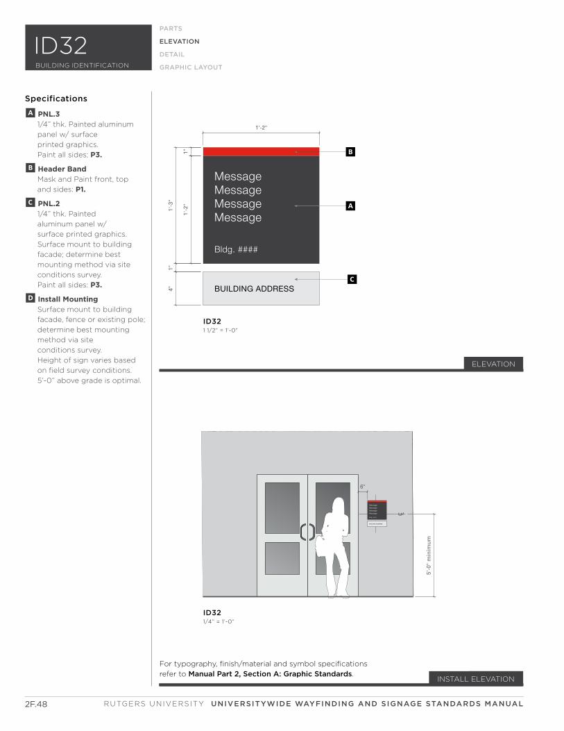
MessageMessageMessageMessage
Bldg. ####
BUILDING ADDRESS
C L
Park ing Only
Univers i ty Hang Tag Required
Unauthor ized Vehic les Wi l l be T icketed
5'-0
" m
inim
um
6"
MessageMessageMessageMessage
Bldg. ####
BUILDING ADDRESS
1'-2"
1"1'
-2"
1'-3
"1"
4"
A
B
C
ID321 1/2” = 1’-0”
ID321/4” = 1’-0”
2F.48
ELEVATION
PARTS
ELEVATION
DETAIL
GRAPHIC LAYOUT
Specifications
For typography, finish/material and symbol specifications
refer to Manual Part 2, Section A: Graphic Standards.
ELEVATION
INSTALL ELEVATION
A PNL.3 1/4” thk. Painted aluminum
panel w/ surface
printed graphics.
Paint all sides: P3.
B Header Band Mask and Paint front, top
and sides: P1.
C PNL.2 1/4” thk. Painted
aluminum panel w/
surface printed graphics.
Surface mount to building
facade; determine best
mounting method via site
conditions survey.
Paint all sides: P3.
D Install Mounting Surface mount to building
facade, fence or existing pole;
determine best mounting
method via site
conditions survey.
Height of sign varies based
on field survey conditions.
5’-0” above grade is optimal.
RUTGERS UNIVERSITY UNIVERSITYWIDE WAYFINDING AND SIGNAGE STANDARDS MANUAL
BUILDING IDENTIFICATION
ID32

Vertical Sectionno scale
at pourous wall surface
Vertical Sectionno scale
at non-pourous wall surface
B
C
A
E
A
D F
2F.49
PARTS
ELEVATION
DETAIL
GRAPHIC LAYOUT
Specifications
A Sign Panel 1/8” thk. Painted aluminum
w/ surface printed copy.
Provide matte clear-coat,
all surfaces.
B Pin-mount Attachment Threaded rod drilled and
tapped into back of cut-out
form. Drill hole in wall
surface and secure w/
hi-bond adhesive.
C Spacer 1/2” dia. x 1/4” d. Aluminum
spacer w/ sandblasted edge
returns. Provide matte
clear-coat, all surfaces.
D Porous Wall Surface
E VHB Foam Tape Attachment 1/16” thk. Exterior grade VHB
foam tape.
F Non-Porous Wall Surface
DETAIL
For typography, finish/material and symbol specifications
refer to Manual Part 2, Section A: Graphic Standards.
SECTION F: BUILDING IDENTIFICATION
ID32BUILDING IDENTIFICATION
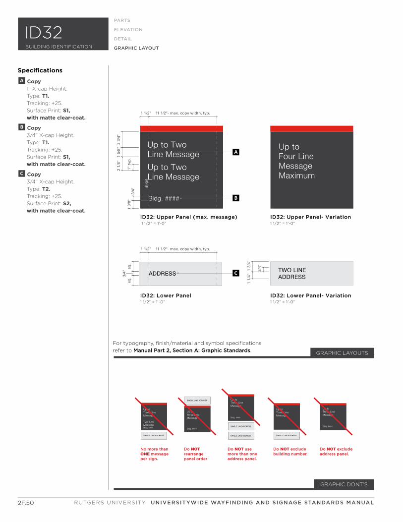
Specifications
RUTGERS UNIVERSITY UNIVERSITYWIDE WAYFINDING AND SIGNAGE STANDARDS MANUAL
Bldg. #### Bldg. ####
Up toThree LineMessage
Bldg. ####
SINGLE LINE ADDRESS Up toThree LineMessage
Bldg. ####
SINGLE LINE ADDRESS
SINGLE LINE ADDRESS
Up toThree LineMessage
SINGLE LINE ADDRESS
Up toThree LineMessage
Two LineMessage
Up toThree LineMessage
SINGLE LINE ADDRESS
Bldg. ####Bldg. ####
Do NOTrearrange panel order
Do NOT use more than one address panel.
Do NOT exclude building number.
Do NOT exclude address panel.
No more than ONE message per sign.
1 1/2" 11 1/2"- max. copy width, typ.
1 1/2" 11 1/2"- max. copy width, typ.
1" t
yp.
1 3/
8"3/
4"eq
.3/
4"eq
.
3/4"
2 3/
4"1
5/8"
2 1/
8"
1 3/
4"1
1/4"
alig
n
ID32: Lower Panel1 1/2” = 1’-0”
ID32: Upper Panel (max. message) 1 1/2” = 1’-0”
ID32: Lower Panel- Variation1 1/2” = 1’-0”
ID32: Upper Panel- Variation1 1/2” = 1’-0”
A
B
C
PARTS
ELEVATION
DETAIL
GRAPHIC LAYOUT
2F.50
BUILDING IDENTIFICATION
ID32
For typography, finish/material and symbol specifications
refer to Manual Part 2, Section A: Graphic Standards.
Specifications
A Copy 1” X-cap Height.
Type: T1. Tracking: +25.
Surface Print: S1, with matte clear-coat.
B Copy 3/4” X-cap Height.
Type: T1. Tracking: +25.
Surface Print: S1, with matte clear-coat.
C Copy 3/4” X-cap Height.
Type: T2. Tracking: +25.
Surface Print: S2, with matte clear-coat.
GRAPHIC DONT’S
GRAPHIC LAYOUTS
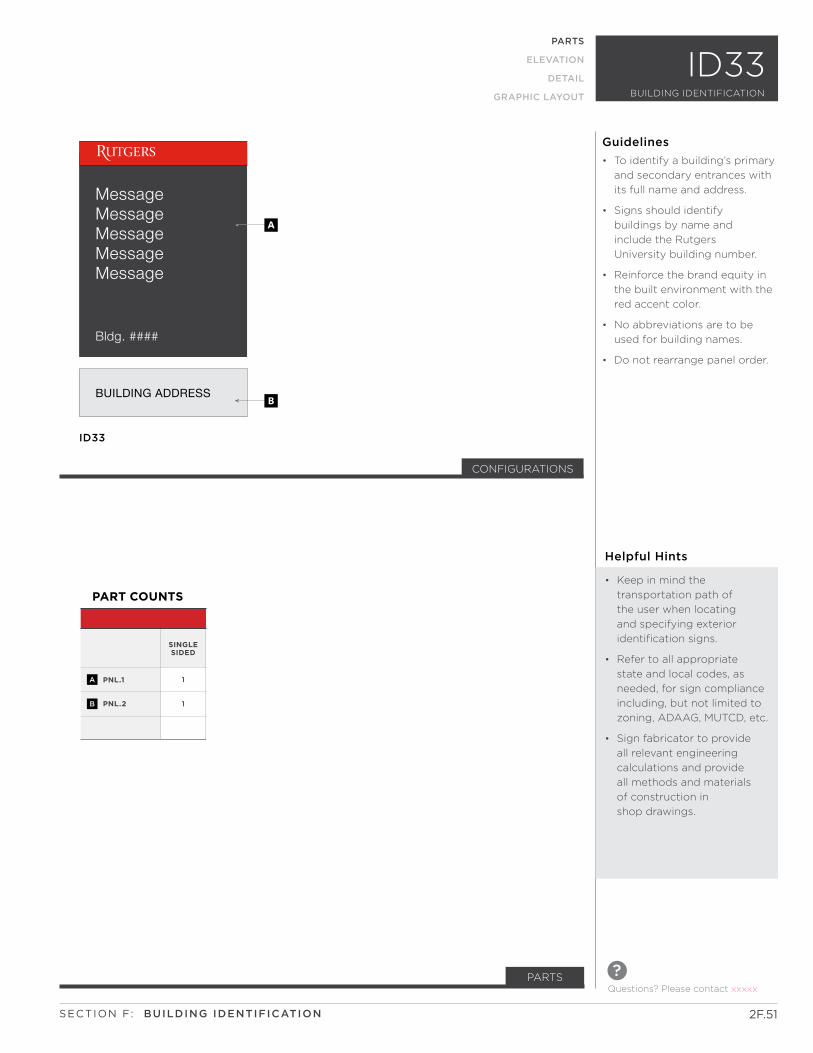
Up to Three Line Message
BUILDING ADDRESS BUILDING ADDRESS
Up to TwoLine Message
Configuration 1 Configuration 2
a
C
D
GB
E
F
H
I
Full length filler panels are used for single side signs only. (not shown)
Stop panel below grade line. (not shown)
19’’
MessageMessageMessageMessageMessage
Bldg. ####
BUILDING ADDRESS
ID33
B
A
CONFIGURATIONS
PNL.1
PNL.2
1
1
PART COUNTS
SINGLE SIDED
A
B
ID33PARTS
ELEVATION
DETAIL
GRAPHIC LAYOUT
Helpful Hints
• Keep in mind the
transportation path of
the user when locating
and specifying exterior
identification signs.
• Refer to all appropriate
state and local codes, as
needed, for sign compliance
including, but not limited to
zoning, ADAAG, MUTCD, etc.
• Sign fabricator to provide
all relevant engineering
calculations and provide
all methods and materials
of construction in
shop drawings.
• To identify a building’s primary
and secondary entrances with
its full name and address.
• Signs should identify
buildings by name and
include the Rutgers
University building number.
• Reinforce the brand equity in
the built environment with the
red accent color.
• No abbreviations are to be
used for building names.
• Do not rearrange panel order.
Guidelines
2F.51
Questions? Please contact xxxxx
?PARTS
SECTION F: BUILDING IDENTIFICATION
BUILDING IDENTIFICATION
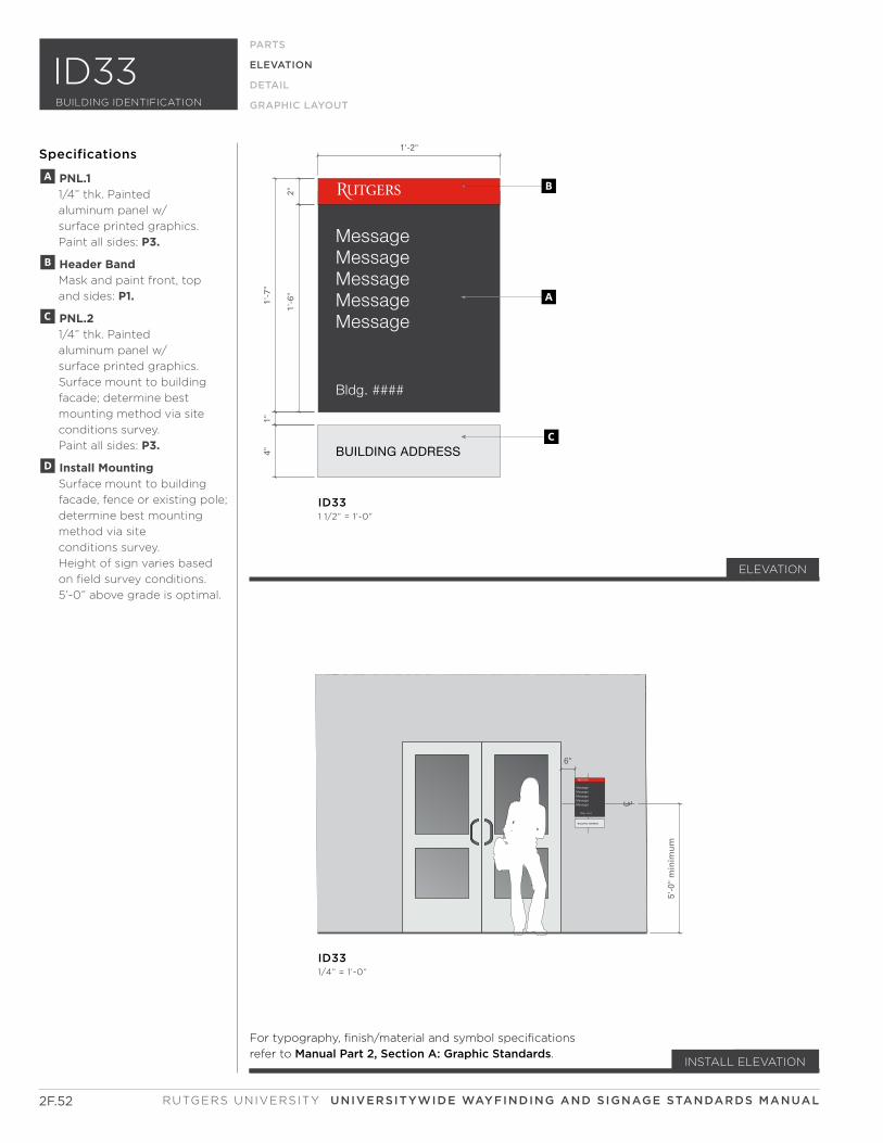
MessageMessageMessageMessageMessage
Bldg. ####
BUILDING ADDRESS
C L
5'-0
" m
inim
um
6"
MessageMessageMessageMessageMessage
Bldg. ####
BUILDING ADDRESS
1'-2"
2"1'
-6"
1'-7
"1"
4"
A
B
C
ID331 1/2” = 1’-0”
ID331/4” = 1’-0”
2F.52
ELEVATION
PARTS
ELEVATION
DETAIL
GRAPHIC LAYOUT
Specifications
For typography, finish/material and symbol specifications
refer to Manual Part 2, Section A: Graphic Standards.
ELEVATION
INSTALL ELEVATION
A PNL.1 1/4” thk. Painted
aluminum panel w/
surface printed graphics.
Paint all sides: P3.
B Header Band Mask and paint front, top
and sides: P1.
C PNL.2 1/4” thk. Painted
aluminum panel w/
surface printed graphics.
Surface mount to building
facade; determine best
mounting method via site
conditions survey.
Paint all sides: P3.
D Install Mounting Surface mount to building
facade, fence or existing pole;
determine best mounting
method via site
conditions survey.
Height of sign varies based
on field survey conditions.
5’-0” above grade is optimal.
RUTGERS UNIVERSITY UNIVERSITYWIDE WAYFINDING AND SIGNAGE STANDARDS MANUAL
BUILDING IDENTIFICATION
ID33

Vertical Sectionno scale
at pourous wall surface
Vertical Sectionno scale
at non-pourous wall surface
B
C
A
E
A
D F
2F.53
PARTS
ELEVATION
DETAIL
GRAPHIC LAYOUT
Specifications
A Sign Panel 1/8” thk. Painted aluminum
w/ surface printed copy.
Provide matte clear-coat,
all surfaces.
B Pin-mount Attachment Threaded rod drilled and
tapped into back of cut-out
form. Drill hole in wall
surface and secure w/
hi-bond adhesive.
C Spacer 1/2” dia. x 1/4” d. Aluminum
spacer w/ sandblasted edge
returns. Provide matte
clear-coat, all surfaces.
D Porous Wall Surface
E VHB Foam Tape Attachment 1/16” thk. Exterior grade VHB
foam tape.
F Non-Porous Wall Surface
DETAIL
SECTION F: BUILDING IDENTIFICATION
ID33BUILDING IDENTIFICATION
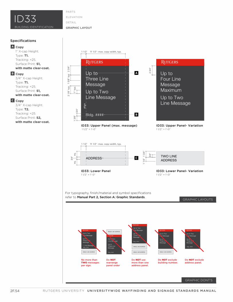
Up to TwoLine Message
Up toThree LineMessage
Bldg. ####
SINGLE LINE ADDRESS
Up to TwoLine Message
Up toThree LineMessage
Bldg. ####
SINGLE LINE ADDRESS
SINGLE LINE ADDRESS
Up to TwoLine Message
Up toThree LineMessage
SINGLE LINE ADDRESS
Up to TwoLine Message
Up toThree LineMessage
Up to TwoLine Message
Up toThree LineMessage
SINGLE LINE ADDRESS
Bldg. ####Bldg. ####1 Line Message
Do NOTrearrange panel order
Do NOT use more than one address panel.
Do NOT exclude building number.
Do NOT exclude address panel.
No more than TWO messages per sign.
1 1/2" 11 1/2"- max. copy width, typ.
1 1/2" 11 1/2"- max. copy width, typ.
1" t
yp.
1 3/
8"3/
4"eq
.3/
4"eq
.
3/4"
2 1/
8" t
yp.
1 3/
4"1
1/4"
2 3/
4"1
5/8"
typ
2 3/
4"
alig
n
ID33: Lower Panel1 1/2” = 1’-0”
ID33: Upper Panel (max. message) 1 1/2” = 1’-0”
ID33: Lower Panel- Variation1 1/2” = 1’-0”
ID33: Upper Panel- Variation1 1/2” = 1’-0”
A
B
C
For typography, finish/material and symbol specifications
refer to Manual Part 2, Section A: Graphic Standards.
Specifications
A Copy 1” X-cap Height.
Type: T1. Tracking: +25.
Surface Print: S1, with matte clear-coat.
B Copy 3/4” X-cap Height.
Type: T1. Tracking: +25.
Surface Print: S1, with matte clear-coat.
C Copy 3/4” X-cap Height.
Type: T2. Tracking: +25.
Surface Print: S2, with matte clear-coat.
GRAPHIC DONT’S
GRAPHIC LAYOUTS
RUTGERS UNIVERSITY UNIVERSITYWIDE WAYFINDING AND SIGNAGE STANDARDS MANUAL
PARTS
ELEVATION
DETAIL
GRAPHIC LAYOUT
2F.54
BUILDING IDENTIFICATION
ID33
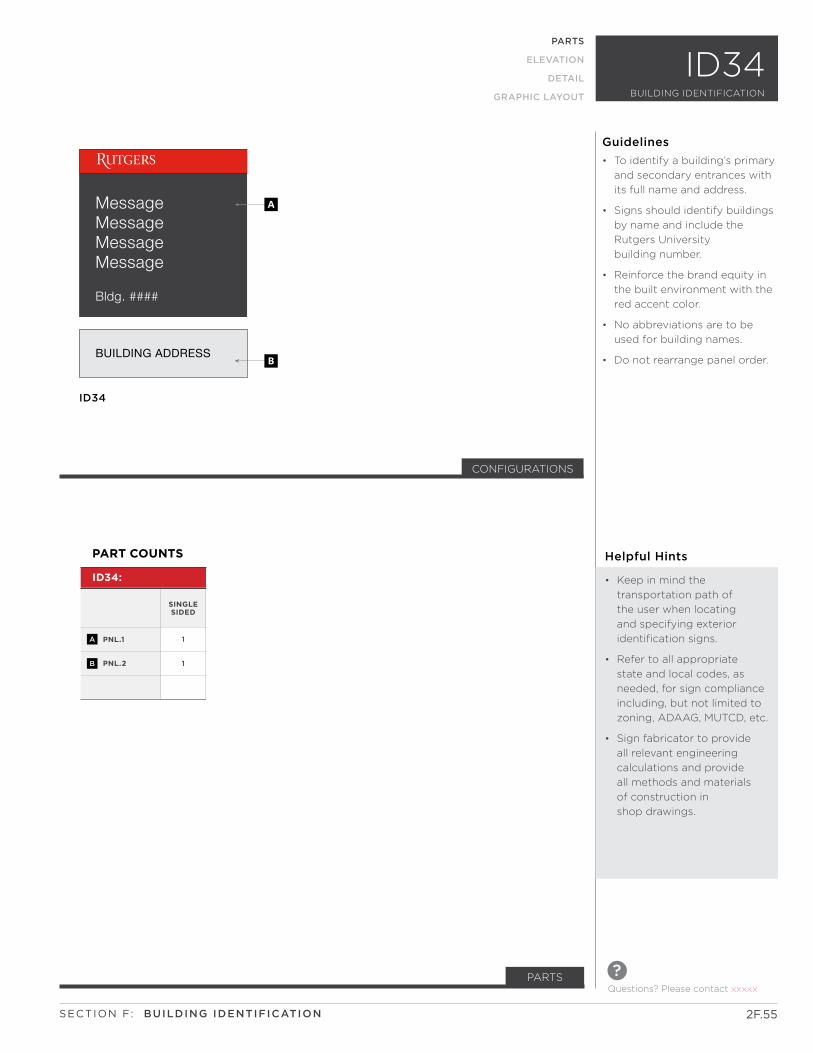
Bldg. ####
BUILDING ADDRESS
MessageMessageMessageMessage
ID34
B
A
CONFIGURATIONS
PNL.1
PNL.2
1
1
ID34:
PART COUNTS
SINGLE SIDED
A
B
ID34PARTS
ELEVATION
DETAIL
GRAPHIC LAYOUT
Helpful Hints
• Keep in mind the
transportation path of
the user when locating
and specifying exterior
identification signs.
• Refer to all appropriate
state and local codes, as
needed, for sign compliance
including, but not limited to
zoning, ADAAG, MUTCD, etc.
• Sign fabricator to provide
all relevant engineering
calculations and provide
all methods and materials
of construction in
shop drawings.
• To identify a building’s primary
and secondary entrances with
its full name and address.
• Signs should identify buildings
by name and include the
Rutgers University
building number.
• Reinforce the brand equity in
the built environment with the
red accent color.
• No abbreviations are to be
used for building names.
• Do not rearrange panel order.
Guidelines
2F.55
Questions? Please contact xxxxx
?PARTS
SECTION F: BUILDING IDENTIFICATION
BUILDING IDENTIFICATION
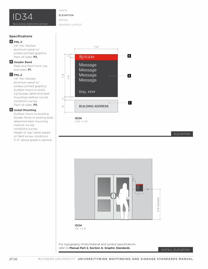
MessageMessageMessageMessage
Bldg. ####
BUILDING ADDRESS
C L
5'-0
" m
inim
um
6"
MessageMessageMessageMessage
Bldg. ####
BUILDING ADDRESS
1'-2"
1"1'
-2"
1'-3
"1"
4"
A
B
C
ID341 1/2” = 1’-0”
ID341/4” = 1’-0”
2F.56
ELEVATION
PARTS
ELEVATION
DETAIL
GRAPHIC LAYOUT
Specifications
For typography, finish/material and symbol specifications
refer to Manual Part 2, Section A: Graphic Standards.
ELEVATION
INSTALL ELEVATION
A PNL.3 1/4” thk. Painted
aluminum panel w/
surface printed graphics.
Paint all sides: P3.
B Header Band Mask and Paint front, top
and sides: P1.
C PNL.2 1/4” thk. Painted
aluminum panel w/
surface printed graphics.
Surface mount to build-
ing facade; determine best
mounting method via site
conditions survey.
Paint all sides: P3.
D Install Mounting Surface mount to building
facade, fence or existing pole;
determine best mounting
method via site
conditions survey.
Height of sign varies based
on field survey conditions.
5’-0” above grade is optimal.
RUTGERS UNIVERSITY UNIVERSITYWIDE WAYFINDING AND SIGNAGE STANDARDS MANUAL
BUILDING IDENTIFICATION
ID34

Vertical Sectionno scale
at pourous wall surface
Vertical Sectionno scale
at non-pourous wall surface
B
C
A
E
A
D F
2F.57
PARTS
ELEVATION
DETAIL
GRAPHIC LAYOUT
Specifications
A Sign Panel 1/8” thk. Painted aluminum
w/ surface printed copy.
Provide matte clear-coat,
all surfaces.
B Pin-mount Attachment Threaded rod drilled and
tapped into back of cut-out
form. Drill hole in wall sur-
face and secure w/
hi-bond adhesive.
C Spacer 1/2” dia. x 1/4” d. Aluminum
spacer w/ sandblasted edge
returns. Provide matte clear-
coat, all surfaces.
D Porous Wall Surface
E VHB Foam Tape Attachment 1/16” thk. Exterior grade VHB
foam tape.
F Non-Porous Wall Surface
DETAIL
SECTION F: BUILDING IDENTIFICATION
ID34BUILDING IDENTIFICATION
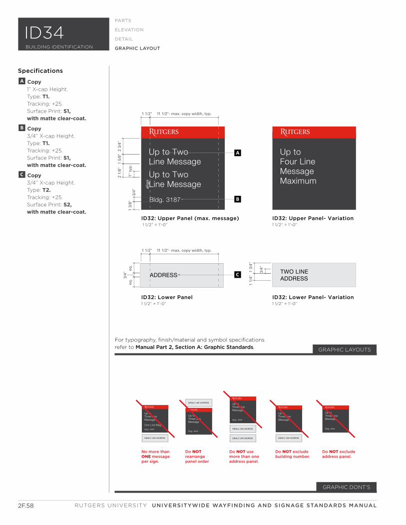
RUTGERS UNIVERSITY UNIVERSITYWIDE WAYFINDING AND SIGNAGE STANDARDS MANUAL
Bldg. 3187
Up toThree LineMessage
Bldg. ####
SINGLE LINE ADDRESS Up toThree LineMessage
Bldg. ####
SINGLE LINE ADDRESS
SINGLE LINE ADDRESS
Up toThree LineMessage
SINGLE LINE ADDRESS
Up toThree LineMessage
One Line Msg
Up toThree LineMessage
SINGLE LINE ADDRESS
Bldg. ####Bldg. ####
Do NOTrearrange panel order
Do NOT use more than one address panel.
Do NOT exclude building number.
Do NOT exclude address panel.
No more than ONE message per sign.
1 1/2" 11 1/2"- max. copy width, typ.
1 1/2" 11 1/2"- max. copy width, typ.
1" t
yp.
1 3/
8"3/
4"eq
.3/
4"eq
.
3/4"
2 3/
4"1
5/8"
2 1/
8"
1 3/
4"1
1/4"
alig
n
ID32: Lower Panel1 1/2” = 1’-0”
ID32: Upper Panel (max. message) 1 1/2” = 1’-0”
ID32: Lower Panel- Variation1 1/2” = 1’-0”
ID32: Upper Panel- Variation1 1/2” = 1’-0”
A
B
C
2F.58
BUILDING IDENTIFICATION
ID34
Specifications
A Copy 1” X-cap Height.
Type: T1. Tracking: +25.
Surface Print: S1, with matte clear-coat.
B Copy 3/4” X-cap Height.
Type: T1. Tracking: +25.
Surface Print: S1, with matte clear-coat.
C Copy 3/4” X-cap Height.
Type: T2. Tracking: +25.
Surface Print: S2, with matte clear-coat.
GRAPHIC DONT’S
GRAPHIC LAYOUTS
For typography, finish/material and symbol specifications
refer to Manual Part 2, Section A: Graphic Standards.
PARTS
ELEVATION
DETAIL
GRAPHIC LAYOUT

SECTION F:
ID40 SERIES
SUB-SECTION
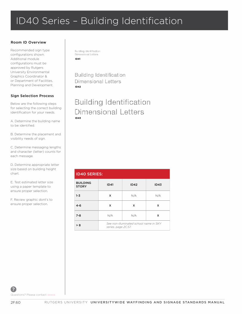
2F.60
ID40 Series – Building Identification
Room ID Overview
Questions? Please contact xxxxx
?
RUTGERS UNIVERSITY UNIVERSITYWIDE WAYFINDING AND SIGNAGE STANDARDS MANUAL
Recommended sign type
configurations shown.
Additional module
configurations must be
approved by Rutgers
University Environmental
Graphics Coordinator &
or Department of Facilities,
Planning and Development.
ID41
ID43
ID42
ID40 SERIES:
1-3
BUILDING STORY
> 8
ID41 ID42 ID43
X
4-6 X X X
N/A N/A
7-8 XN/AN/A
See non-illuminated school name in SKYseries, page 2C.57.
Below are the following steps
for selecting the correct building
identification for your needs.
A. Determine the building name
to be identified.
B. Determine the placement and
visibility needs of sign.
C. Determine messaging lengths
and character (letter) counts for
each message.
D. Determine appropriate letter
size based on building height
chart.
E. Test estimated letter size
using a paper template to
ensure proper selection.
F. Review graphic dont’s to
ensure proper selection.
Sign Selection Process
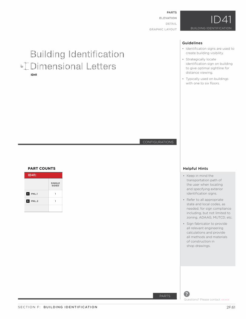
PARTS
ELEVATION
DETAIL
GRAPHIC LAYOUT BUILDING IDENTIFICAITION
ID41
2F.61
Questions? Please contact xxxxx
?PARTS
SECTION F: BUILDING IDENTIFICATION
ID41
6"
CONFIGURATIONS
PNL.1
PNL.2
1
1
ID41:
PART COUNTS
SINGLE SIDED
A
B
ID41BUILDING IDENTIFICATION
PARTS
ELEVATION
DETAIL
GRAPHIC LAYOUT
Helpful Hints
• Keep in mind the
transportation path of
the user when locating
and specifying exterior
identification signs.
• Refer to all appropriate
state and local codes, as
needed, for sign compliance
including, but not limited to
zoning, ADAAG, MUTCD, etc.
• Sign fabricator to provide
all relevant engineering
calculations and provide
all methods and materials
of construction in
shop drawings.
• Identification signs are used to
create building visibility.
• Strategically locate
identification sign on building
to give optimal sightline for
distance viewing.
• Typically used on buildings
with one to six floors.
Guidelines
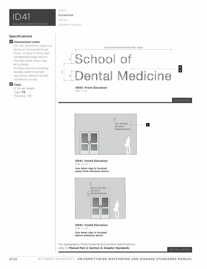
alig
n
alig
n
overall width determined by letter height
11"
6"6"
8"11
"DR41: Front Elevation3/8” = 1’-0”
BA
DR41: Install Elevation3/16” = 1’-0”
Use when sign is locatedabove entrance doors
DR41: Install Elevation3/16” = 1’-0”
Use when sign is locatedaway from entrance doors
c
Dental Medicine
School of Dental Medicine
3rd Line of Text
School of Dental Medicine
3rd Line Text
2F.62
PARTS
ELEVATION
DETAIL
GRAPHIC LAYOUT
Specifications
INSTALLATION
A Dimensional Letter 1/2” thk. Aluminum, laser-cut
forms w/ horizontal brush
finish, on face of form, and
sandblasted edge returns.
Provide matte clear-coat,
all surfaces.
Surface mount to building
facade; determine best
mounting method via site
conditions survey.
B Copy 6” X-cap Height.
Type: T2. Tracking: +25.
ELEVATION
For typography, finish/material and symbol specifications
refer to Manual Part 2, Section A: Graphic Standards.
RUTGERS UNIVERSITY UNIVERSITYWIDE WAYFINDING AND SIGNAGE STANDARDS MANUAL
BUILDING IDENTIFICATION
ID41

6" (
hei
gh
t sh
ow
n)
see
lett
er h
eig
ht
char
t o
nsh
eet
x.xx
fo
r al
tern
ate
hei
gh
ts
6" (
hei
gh
t sh
ow
n)
see
lett
er h
eig
ht
char
t o
nsh
eet
x.xx
fo
r al
tern
ate
hei
gh
ts
5/8"
1/8"1/2"1/2"
DR41: Side Elevation3” = 1’-0”
Use at all porous surface material where VHB tapeis not sufficient to hold cut-out forms in place.
DR41: Side Elevation3” = 1’-0”
Use at all non-porous surface material where VHB tapeis sufficient to hold cut-out forms in place.
AA
F
GG
D
E
2F.63
PARTS
ELEVATION
DETAIL
GRAPHIC LAYOUT
Specifications
C Installation Note If building identification
letters are not located
above the entrance doors,
a site conditions survey
must be done prior to
fabrication. This survey to
include documented
dimensions and notes as
well as photographs.
D Spacer 1/2” dia. x 1/4” d. Aluminum
spacer w/ sandblasted edge
returns. Provide matte
clear-coat, all surfaces.
E Pin-mount Attachment Threaded rod drilled and
tapped into back of cut-out
form. Drill hole in wall
surface and secure w/
hi-bond adhesive.
F VHB Foam Tape Attachment 1/16” thk. Exterior grade VHB
foam tape.
G Architectural Wall Surface
DETAIL
SECTION F: BUILDING IDENTIFICATION
BUILDING IDENTIFICATION
ID41

2F.64 RUTGERS UNIVERSITY UNIVERSITYWIDE WAYFINDING AND SIGNAGE STANDARDS MANUAL
This Page Intentionally Left Blank
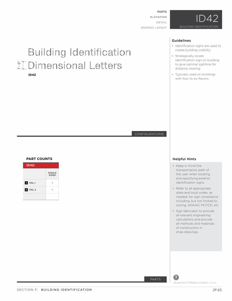
PARTS
ELEVATION
DETAIL
GRAPHIC LAYOUT BUILDING IDENTIFICAITION
ID41
2F.65
Questions? Please contact xxxxx
?PARTS
SECTION F: BUILDING IDENTIFICATION
ID42
1'-
0"
CONFIGURATIONS
PNL.1
PNL.2
1
1
ID42:
PART COUNTS
SINGLE SIDED
A
B
ID42BUILDING IDENTIFICATION
PARTS
ELEVATION
DETAIL
GRAPHIC LAYOUT
Helpful Hints
• Keep in mind the
transportation path of
the user when locating
and specifying exterior
identification signs.
• Refer to all appropriate
state and local codes, as
needed, for sign compliance
including, but not limited to
zoning, ADAAG, MUTCD, etc.
• Sign fabricator to provide
all relevant engineering
calculations and provide
all methods and materials
of construction in
shop drawings.
• Identification signs are used to
create building visibility.
• Strategically locate
identification sign on building
to give optimal sightline for
distance viewing.
• Typically used on buildings
with four to six flavors.
Guidelines
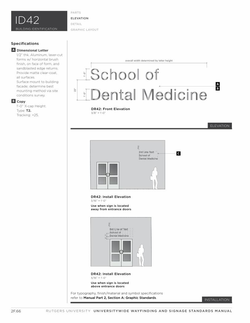
alig
n
alig
n
overall width determined by letter height
22"
1'-0
"1'
-0"
8"11
"
DR42: Front Elevation3/8” = 1’-0”
BA
DR42: Install Elevation3/16” = 1’-0”
Use when sign is locatedabove entrance doors
DR42: Install Elevation3/16” = 1’-0”
Use when sign is locatedaway from entrance doors
C
Dental Medicine
School of Dental Medicine
3rd Line of Text
School of Dental Medicine
3rd Line Text
2F.66
ELEVATION
PARTS
ELEVATION
DETAIL
GRAPHIC LAYOUT
Specifications
A Dimensional Letter 1/2” thk. Aluminum, laser-cut
forms w/ horizontal brush
finish, on face of form, and
sandblasted edge returns.
Provide matte clear-coat,
all surfaces.
Surface mount to building
facade; determine best
mounting method via site
conditions survey.
B Copy 1’-0” X-cap Height.
Type: T2. Tracking: +25.
INSTALLATION
ELEVATION
For typography, finish/material and symbol specifications
refer to Manual Part 2, Section A: Graphic Standards.
RUTGERS UNIVERSITY UNIVERSITYWIDE WAYFINDING AND SIGNAGE STANDARDS MANUAL
BUILDING IDENTIFICATION
ID42
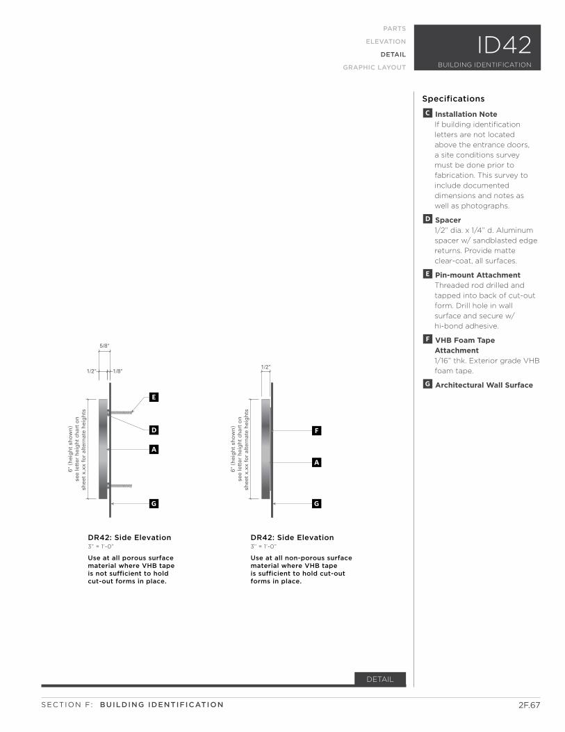
6" (
hei
gh
t sh
ow
n)
see
lett
er h
eig
ht
char
t o
nsh
eet
x.xx
fo
r al
tern
ate
hei
gh
ts
6" (
hei
gh
t sh
ow
n)
see
lett
er h
eig
ht
char
t o
nsh
eet
x.xx
fo
r al
tern
ate
hei
gh
ts
5/8"
1/8"1/2"1/2"
DR42: Side Elevation3” = 1’-0”
Use at all porous surface material where VHB tapeis not sufficient to hold cut-out forms in place.
DR42: Side Elevation3” = 1’-0”
Use at all non-porous surface material where VHB tapeis sufficient to hold cut-out forms in place.
AA
F
GG
D
E
2F.67
PARTS
ELEVATION
DETAIL
GRAPHIC LAYOUT
Specifications
C Installation Note If building identification
letters are not located
above the entrance doors,
a site conditions survey
must be done prior to
fabrication. This survey to
include documented
dimensions and notes as
well as photographs.
D Spacer 1/2” dia. x 1/4” d. Aluminum
spacer w/ sandblasted edge
returns. Provide matte
clear-coat, all surfaces.
E Pin-mount Attachment Threaded rod drilled and
tapped into back of cut-out
form. Drill hole in wall
surface and secure w/
hi-bond adhesive.
F VHB Foam Tape Attachment 1/16” thk. Exterior grade VHB
foam tape.
G Architectural Wall Surface
DETAIL
SECTION F: BUILDING IDENTIFICATION
BUILDING IDENTIFICATION
ID42

2F.68 RUTGERS UNIVERSITY UNIVERSITYWIDE WAYFINDING AND SIGNAGE STANDARDS MANUAL
This Page Intentionally Left Blank
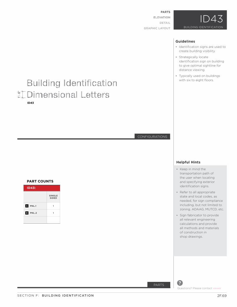
PARTS
ELEVATION
DETAIL
GRAPHIC LAYOUT BUILDING IDENTIFICAITION
ID41
2F.69
Questions? Please contact xxxxx
?PARTS
SECTION F: BUILDING IDENTIFICATION
ID43
1'-
6"
CONFIGURATIONS
PNL.1
PNL.2
1
1
ID43:
PART COUNTS
SINGLE SIDED
A
B
ID43BUILDING IDENTIFICATION
PARTS
ELEVATION
DETAIL
GRAPHIC LAYOUT
Helpful Hints
• Keep in mind the
transportation path of
the user when locating
and specifying exterior
identification signs.
• Refer to all appropriate
state and local codes, as
needed, for sign compliance
including, but not limited to
zoning, ADAAG, MUTCD, etc.
• Sign fabricator to provide
all relevant engineering
calculations and provide
all methods and materials
of construction in
shop drawings.
• Identification signs are used to
create building visibility.
• Strategically locate
identification sign on building
to give optimal sightline for
distance viewing.
• Typically used on buildings
with six to eight floors.
Guidelines
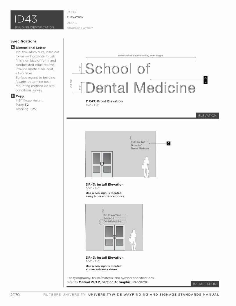
alig
n
alig
n
overall width determined by letter height
2'-8
1/2
"
1'-6
"1'
-6"
8"11
"DR43: Front Elevation1/4” = 1’-0”
BA
DR43: Install Elevation3/16” = 1’-0”
Use when sign is locatedabove entrance doors
DR43: Install Elevation3/16” = 1’-0”
Use when sign is locatedaway from entrance doors
C
Dental Medicine
School of Dental Medicine
3rd Line of Text
School of Dental Medicine
3rd Line Text
2F.70
ELEVATION
PARTS
ELEVATION
DETAIL
GRAPHIC LAYOUT
Specifications
INSTALLATION
ELEVATION
For typography, finish/material and symbol specifications
refer to Manual Part 2, Section A: Graphic Standards.
A Dimensional Letter 1/2” thk. Aluminum, laser-cut
forms w/ horizontal brush
finish, on face of form, and
sandblasted edge returns.
Provide matte clear-coat,
all surfaces.
Surface mount to building
facade; determine best
mounting method via site
conditions survey.
B Copy 1’-6” X-cap Height.
Type: T2. Tracking: +25.
RUTGERS UNIVERSITY UNIVERSITYWIDE WAYFINDING AND SIGNAGE STANDARDS MANUAL
BUILDING IDENTIFICATION
ID43
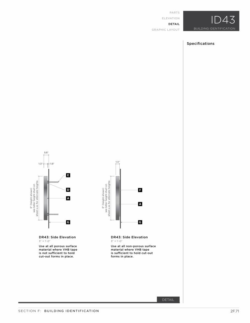
6" (
hei
gh
t sh
ow
n)
see
lett
er h
eig
ht
char
t o
nsh
eet
x.xx
fo
r al
tern
ate
hei
gh
ts
6" (
hei
gh
t sh
ow
n)
see
lett
er h
eig
ht
char
t o
nsh
eet
x.xx
fo
r al
tern
ate
hei
gh
ts
5/8"
1/8"1/2"1/2"
DR43: Side Elevation3” = 1’-0”
Use at all porous surface material where VHB tapeis not sufficient to hold cut-out forms in place.
DR43: Side Elevation3” = 1’-0”
Use at all non-porous surface material where VHB tapeis sufficient to hold cut-out forms in place.
AA
F
GG
D
E
2F.71
PARTS
ELEVATION
DETAIL
GRAPHIC LAYOUT
Specifications
DETAIL
SECTION F: BUILDING IDENTIFICATION
BUILDING IDENTIFICATION
ID43
2F.72 RUTGERS UNIVERSITY SIGNAGE STANDARDS MANUAL
This Page Intentionally Left Blank

SUB-SECTION
SECTION F:
ID50 SERIES
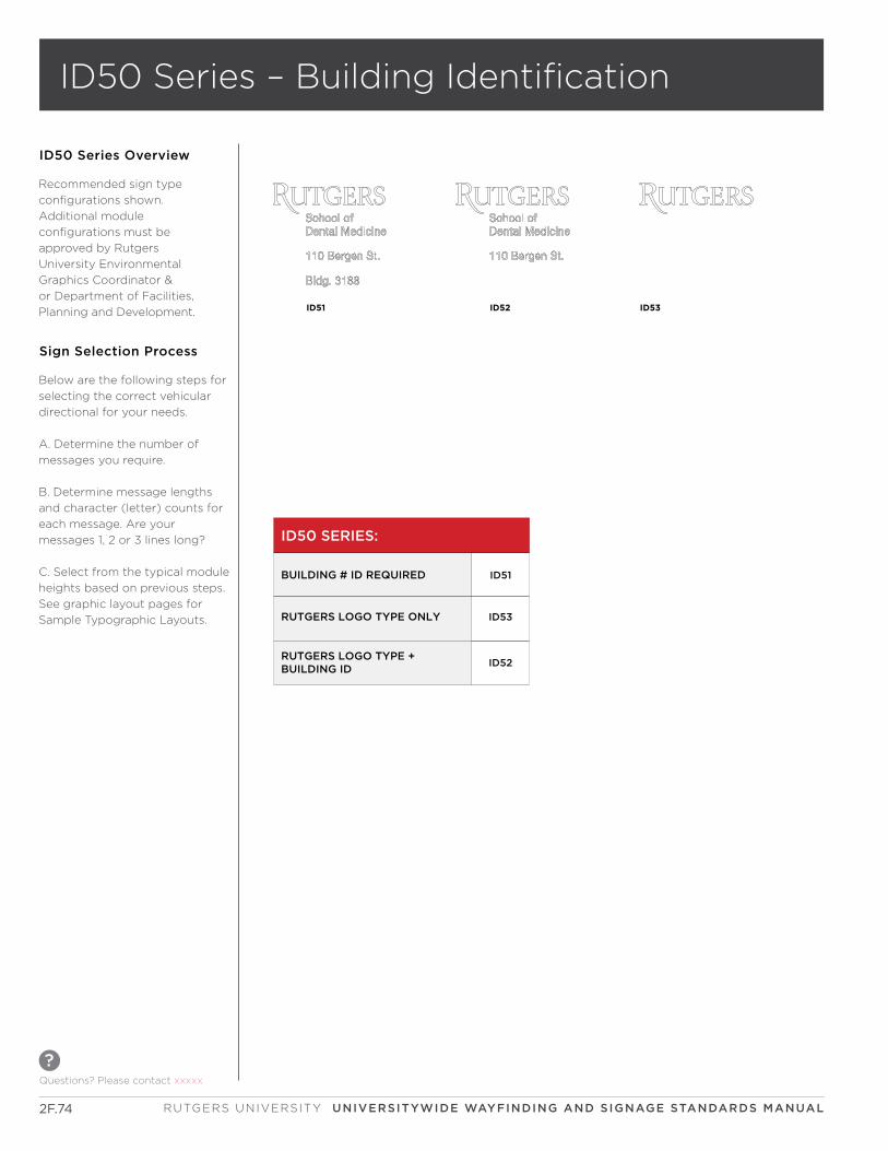
2F.74
Questions? Please contact xxxxx
?
RUTGERS UNIVERSITY UNIVERSITYWIDE WAYFINDING AND SIGNAGE STANDARDS MANUAL
ID50 Series – Building Identification
ID50 Series Overview
Recommended sign type
configurations shown.
Additional module
configurations must be
approved by Rutgers
University Environmental
Graphics Coordinator &
or Department of Facilities,
Planning and Development. ID52 ID53ID51
ID50 SERIES:
BUILDING # ID REQUIRED
RUTGERS LOGO TYPE ONLY
RUTGERS LOGO TYPE +BUILDING ID
ID51
ID53
ID52
Below are the following steps for
selecting the correct vehicular
directional for your needs.
A. Determine the number of
messages you require.
B. Determine message lengths
and character (letter) counts for
each message. Are your
messages 1, 2 or 3 lines long?
C. Select from the typical module
heights based on previous steps.
See graphic layout pages for
Sample Typographic Layouts.
Sign Selection Process
BUILDING IDENTIFICATION
ID51PARTS
ELEVATION
DETAIL
GRAPHIC LAYOUT
Questions? Please contact xxxxx
?
2F.75SECTION F: BUILDING IDENTIFICATION
ID51
CONFIGURATIONS
Helpful Hints
• Keep in mind the
transportation path of
the user when locating
and specifying exterior
identification signs.
• Refer to all appropriate
state and local codes, as
needed, for sign compliance
including, but not limited to
zoning, ADAAG, MUTCD, etc.
• Sign fabricator to provide
all relevant engineering
calculations and provide
all methods and materials
of construction in
shop drawings.
• To identify buildings at building
entrances with the full name,
address and building number.
• Brand: Reinforce the brand
equity in the built environment
with the Rutgers logotype.
• Any combination of these
elements can be used as
necessary for each individual
location. Refer to Rutgers
Visual Identity Manual
for usage.
• No abbreviations are to be
used on building
identification signage.
Guidelines
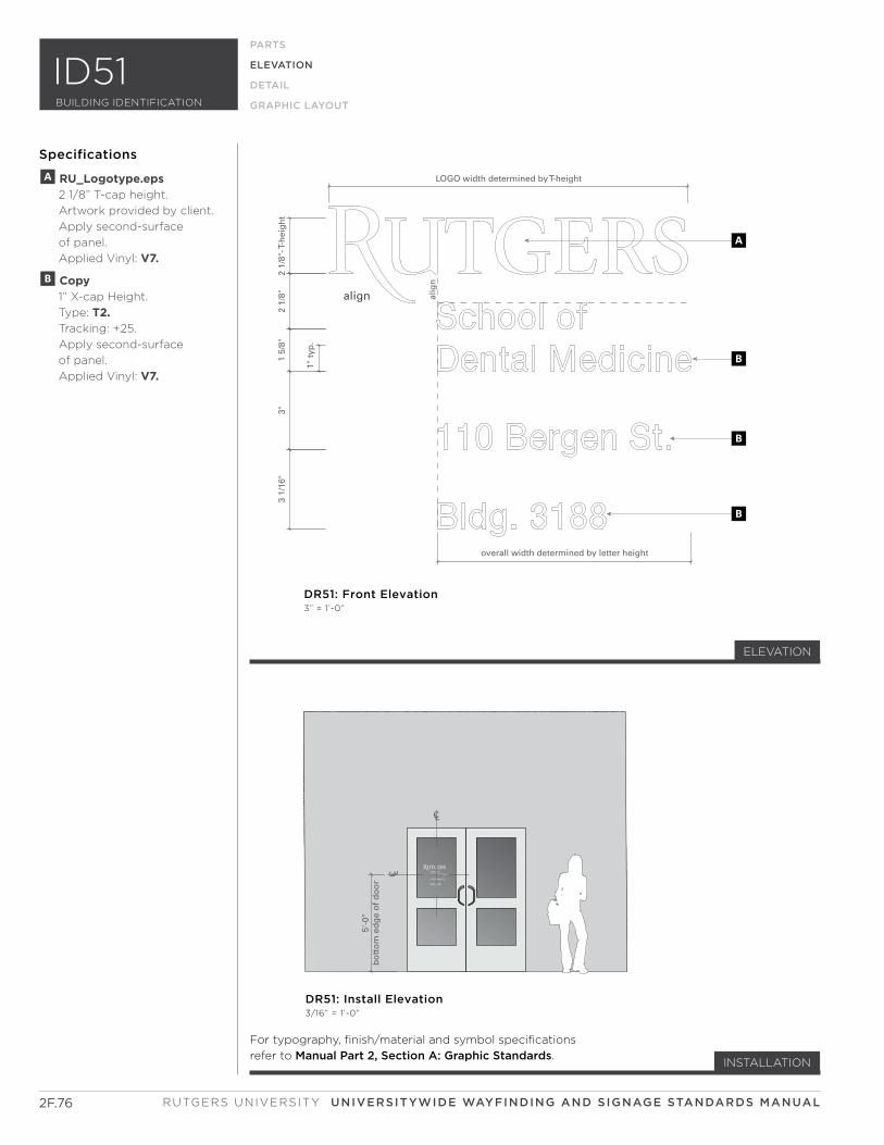
2F.76 RUTGERS UNIVERSITY UNIVERSITYWIDE WAYFINDING AND SIGNAGE STANDARDS MANUAL
For typography, finish/material and symbol specifications
refer to Manual Part 2, Section A: Graphic Standards.
alig
n
align
CL
overall width determined by letter height
2 1/
8"- T
-hei
gh
t2
1/8"
1 5/
8"3"
3 1/
16"
1" t
yp.
5'-0
"b
ott
om
ed
ge
of
do
or
C L
LOGO width determined by T-height
DR51: Install Elevation3/16” = 1’-0”
DR51: Front Elevation3” = 1’-0”
A
B
B
B
PARTS
ELEVATION
DETAIL
GRAPHIC LAYOUT
Specifications
INSTALLATION
A RU_Logotype.eps 2 1/8” T-cap height.
Artwork provided by client.
Apply second-surface
of panel.
Applied Vinyl: V7.
B Copy 1” X-cap Height.
Type: T2. Tracking: +25.
Apply second-surface
of panel.
Applied Vinyl: V7.
ELEVATION
BUILDING IDENTIFICATION
ID51

2F.77SECTION F: BUILDING IDENTIFICATION
Questions? Please contact xxxxx
?
BUILDING IDENTIFICATION
ID52PARTS
ELEVATION
DETAIL
GRAPHIC LAYOUT
ID52
CONFIGURATIONS
Helpful Hints
• Keep in mind the
transportation path of
the user when locating
and specifying exterior
identification signs.
• Refer to all appropriate
state and local codes, as
needed, for sign compliance
including, but not limited to
zoning, ADAAG, MUTCD, etc.
• Sign fabricator to provide
all relevant engineering
calculations and provide
all methods and materials
of construction in
shop drawings.
• To identify buildings at building
entrances with the full name,
address and building number.
• Brand: Reinforce the brand
equity in the built environment
with the Rutgers logotype.
• Any combination of these
elements can be used as
necessary for each individual
location. Refer to Rutgers
Visual Identity Manual
for usage.
• No abbreviations are to be
used on building
identification signage.
Guidelines
PARTS
ELEVATION
DETAIL
GRAPHIC LAYOUT
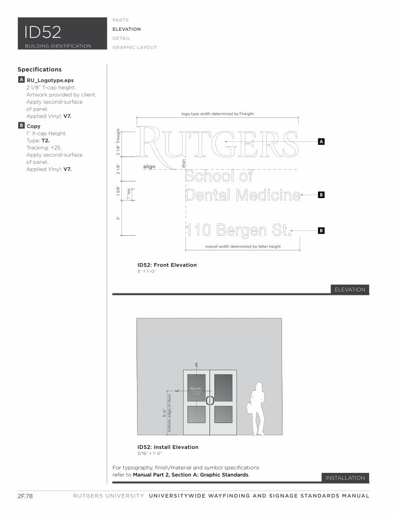
2F.78 RUTGERS UNIVERSITY UNIVERSITYWIDE WAYFINDING AND SIGNAGE STANDARDS MANUAL
alig
n
align
CL
overall width determined by letter height
2 1/
8" T
-hei
gh
t2
1/8"
1 5/
8"3"
1" t
yp.
5'-0
"b
ott
om
ed
ge
of
do
or
C L
logo-type width determined by T-height
ID52: Install Elevation3/16” = 1’-0”
ID52: Front Elevation3” = 1’-0”
A
B
B
PARTS
ELEVATION
DETAIL
GRAPHIC LAYOUT
Specifications
INSTALLATION
A RU_Logotype.eps 2 1/8” T-cap height.
Artwork provided by client.
Apply second-surface
of panel.
Applied Vinyl: V7.
B Copy 1” X-cap Height.
Type: T2. Tracking: +25.
Apply second-surface
of panel.
Applied Vinyl: V7.
ELEVATION
BUILDING IDENTIFICATION
ID52
For typography, finish/material and symbol specifications
refer to Manual Part 2, Section A: Graphic Standards.
2F.79SECTION F: BUILDING IDENTIFICATION
Questions? Please contact xxxxx
?
BUILDING IDENTIFICATION
ID53PARTS
ELEVATION
DETAIL
GRAPHIC LAYOUT
ID53
CONFIGURATIONS
Helpful Hints
• Keep in mind the
transportation path of
the user when locating
and specifying exterior
identification signs.
• Refer to all appropriate
state and local codes, as
needed, for sign compliance
including, but not limited to
zoning, ADAAG, MUTCD, etc.
• Sign fabricator to provide
all relevant engineering
calculations and provide
all methods and materials
of construction in
shop drawings.
• To identify buildings at building
entrances with the full name,
address and building number.
• Brand: Reinforce the brand
equity in the built environment
with the Rutgers logotype.
• Any combination of these
elements can be used as
necessary for each individual
location. Refer to Rutgers
Visual Identity Manual
for usage.
• No abbreviations are to be
used on building
identification signage.
Guidelines
PARTS
ELEVATION
DETAIL
GRAPHIC LAYOUT
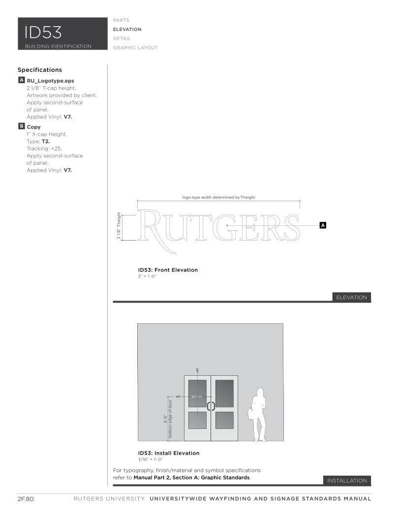
2F.80 RUTGERS UNIVERSITY UNIVERSITYWIDE WAYFINDING AND SIGNAGE STANDARDS MANUAL
CL
2 1/
8" T
-hei
gh
t
5'-0
"b
ott
om
ed
ge
of
do
or
C L
logo-type width determined by T-height
ID53: Install Elevation3/16” = 1’-0”
ID53: Front Elevation3” = 1’-0”
A
PARTS
ELEVATION
DETAIL
GRAPHIC LAYOUT
Specifications
INSTALLATION
A RU_Logotype.eps 2 1/8” T-cap height.
Artwork provided by client.
Apply second-surface
of panel.
Applied Vinyl: V7.
B Copy 1” X-cap Height.
Type: T2. Tracking: +25.
Apply second-surface
of panel.
Applied Vinyl: V7.
ELEVATION
BUILDING IDENTIFICATION
ID53
For typography, finish/material and symbol specifications
refer to Manual Part 2, Section A: Graphic Standards.

SUB-SECTION
SECTION F:
ID60 SERIES
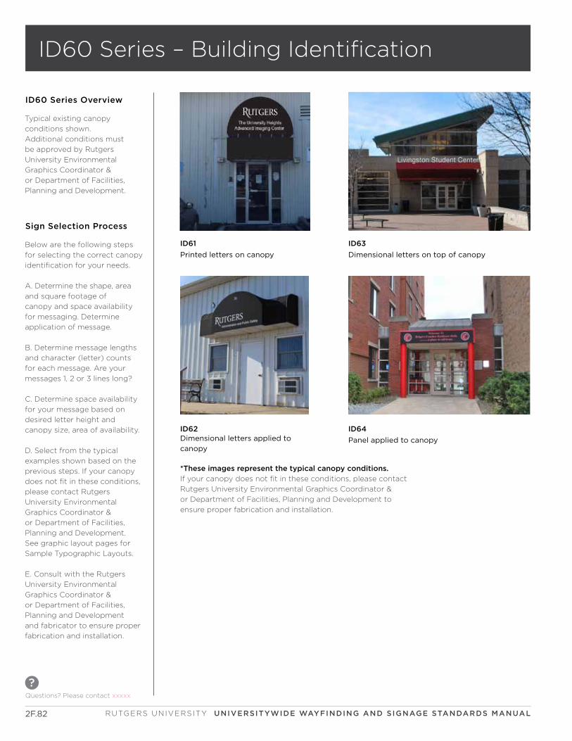
2F.82
Questions? Please contact xxxxx
?
RUTGERS UNIVERSITY UNIVERSITYWIDE WAYFINDING AND SIGNAGE STANDARDS MANUAL
ID60 Series – Building Identification
ID60 Series Overview
Typical existing canopy
conditions shown.
Additional conditions must
be approved by Rutgers
University Environmental
Graphics Coordinator &
or Department of Facilities,
Planning and Development.
Below are the following steps
for selecting the correct canopy
identification for your needs.
A. Determine the shape, area
and square footage of
canopy and space availability
for messaging. Determine
application of message.
B. Determine message lengths
and character (letter) counts
for each message. Are your
messages 1, 2 or 3 lines long?
C. Determine space availability
for your message based on
desired letter height and
canopy size, area of availability.
D. Select from the typical
examples shown based on the
previous steps. If your canopy
does not fit in these conditions,
please contact Rutgers
University Environmental
Graphics Coordinator &
or Department of Facilities,
Planning and Development.
See graphic layout pages for
Sample Typographic Layouts.
E. Consult with the Rutgers
University Environmental
Graphics Coordinator &
or Department of Facilities,
Planning and Development
and fabricator to ensure proper
fabrication and installation.
Sign Selection Process
ID61
Printed letters on canopy
ID63
Dimensional letters on top of canopy
ID62Dimensional letters applied to
canopy
*These images represent the typical canopy conditions.
If your canopy does not fit in these conditions, please contact
Rutgers University Environmental Graphics Coordinator &
or Department of Facilities, Planning and Development to
ensure proper fabrication and installation.
ID64
Panel applied to canopy
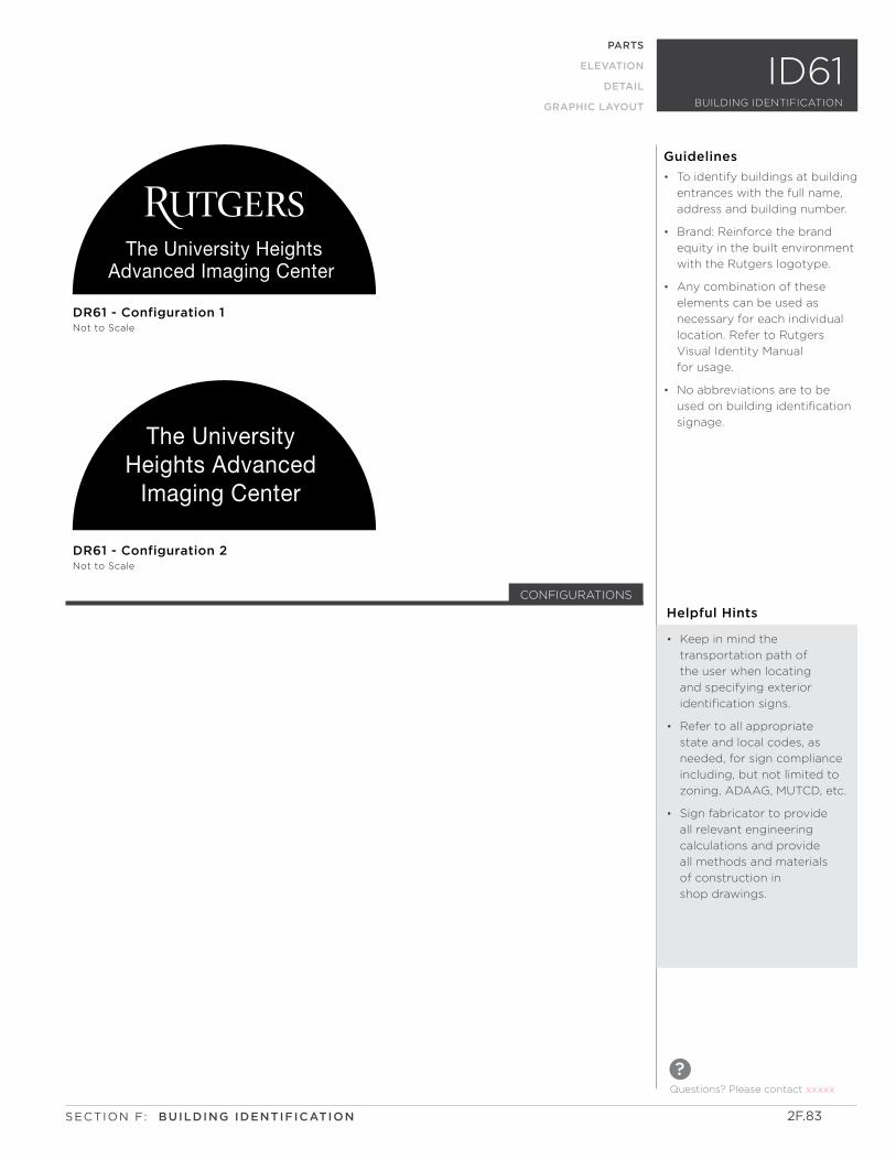
The University HeightsAdvanced Imaging Center
The University Heights Advanced
Imaging Center
DR61 - Configuration 2Not to Scale
DR61 - Configuration 1Not to Scale
BUILDING IDENTIFICATION
ID61PARTS
ELEVATION
DETAIL
GRAPHIC LAYOUT
Questions? Please contact xxxxx
?
2F.83SECTION F: BUILDING IDENTIFICATION
CONFIGURATIONS
Helpful Hints
• Keep in mind the
transportation path of
the user when locating
and specifying exterior
identification signs.
• Refer to all appropriate
state and local codes, as
needed, for sign compliance
including, but not limited to
zoning, ADAAG, MUTCD, etc.
• Sign fabricator to provide
all relevant engineering
calculations and provide
all methods and materials
of construction in
shop drawings.
• To identify buildings at building
entrances with the full name,
address and building number.
• Brand: Reinforce the brand
equity in the built environment
with the Rutgers logotype.
• Any combination of these
elements can be used as
necessary for each individual
location. Refer to Rutgers
Visual Identity Manual
for usage.
• No abbreviations are to be
used on building identification
signage.
Guidelines
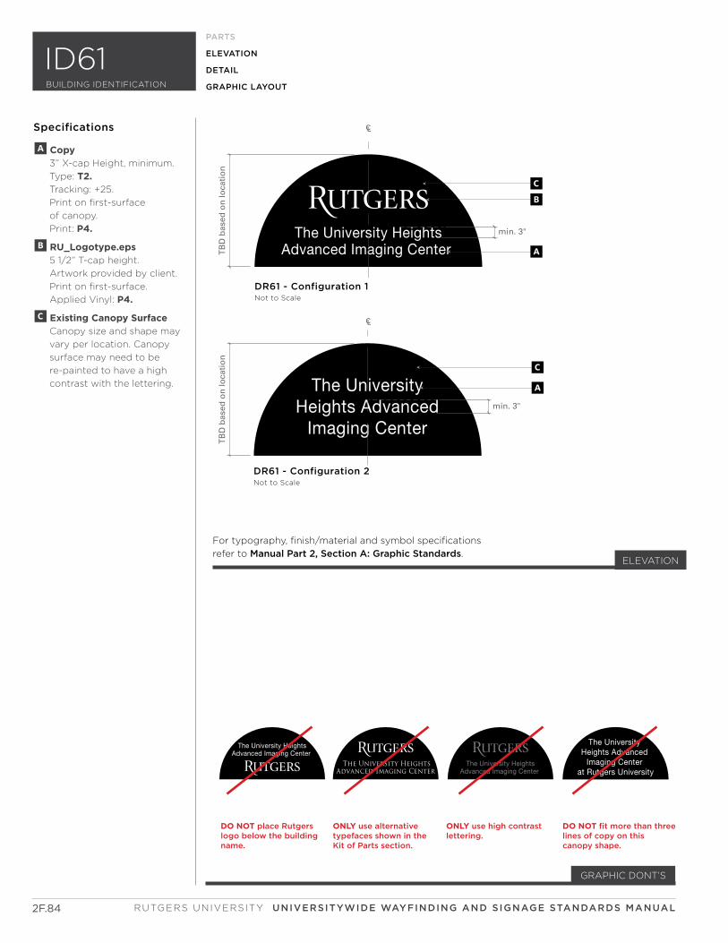
The University HeightsAdvanced Imaging Center
The University HeightsAdvanced Imaging Center
The University HeightsAdvanced Imaging Center
The University HeightsAdvanced Imaging Center
The University Heights Advanced
Imaging Center
CL
CL
DO NOT place Rutgerslogo below the buildingname.
ONLY use alternative typefaces shown in the Kit of Parts section.
ONLY use high contrast lettering.
DO NOT fit more than threelines of copy on this canopy shape.
The University Heights Advanced
Imaging Center at Rutgers University
TB
D b
ased
on
loca
tio
nT
BD
bas
ed o
n lo
cati
on
min. 3"
min. 3"
DR61 - Configuration 2Not to Scale
DR61 - Configuration 1Not to Scale
CB
A
A
C
The University HeightsAdvanced Imaging Center
The University HeightsAdvanced Imaging Center
The University HeightsAdvanced Imaging Center
The University HeightsAdvanced Imaging Center
The University Heights Advanced
Imaging Center
CL
CL
DO NOT place Rutgerslogo below the buildingname.
ONLY use alternative typefaces shown in the Kit of Parts section.
ONLY use high contrast lettering.
DO NOT fit more than threelines of copy on this canopy shape.
The University Heights Advanced
Imaging Center at Rutgers University
TB
D b
ased
on
loca
tio
nT
BD
bas
ed o
n lo
cati
on
min. 3"
min. 3"
DR61 - Configuration 2Not to Scale
DR61 - Configuration 1Not to Scale
CB
A
A
C
2F.84 RUTGERS UNIVERSITY UNIVERSITYWIDE WAYFINDING AND SIGNAGE STANDARDS MANUAL
For typography, finish/material and symbol specifications
refer to Manual Part 2, Section A: Graphic Standards.
A Copy 3” X-cap Height, minimum.
Type: T2. Tracking: +25.
Print on first-surface
of canopy.
Print: P4.
B RU_Logotype.eps 5 1/2” T-cap height.
Artwork provided by client.
Print on first-surface.
Applied Vinyl: P4.
C Existing Canopy Surface Canopy size and shape may
vary per location. Canopy
surface may need to be
re-painted to have a high
contrast with the lettering.
PARTS
ELEVATION
DETAIL
GRAPHIC LAYOUTBUILDING IDENTIFICATION
ID61
Specifications
ELEVATION
GRAPHIC DONT’S
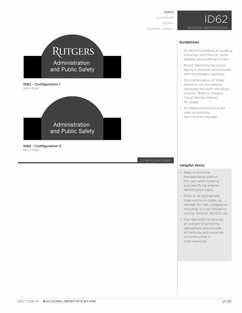
Administration and Public Safety
Administration and Public Safety
Administration and Public Safety
Administration and Public Safety min. 3"
G
A
AC
B
G
AB
CL
CL
ID62 - Configuration 2Not to Scale
ID62 - Configuration 2Not to Scale
ID62 - Configuration 1Not to Scale
ID62 - Configuration 1Not to Scale
2F.85
Guidelines
PARTS
ELEVATION
DETAIL
GRAPHIC LAYOUT
SECTION F: BUILDING IDENTIFICATION
BUILDING IDENTIFICATION
ID62
Helpful Hints
• Keep in mind the
transportation path of
the user when locating
and specifying exterior
identification signs.
• Refer to all appropriate
state and local codes, as
needed, for sign compliance
including, but not limited to
zoning, ADAAG, MUTCD, etc.
• Sign fabricator to provide
all relevant engineering
calculations and provide
all methods and materials
of construction in
shop drawings.
• To identify buildings at building
entrances with the full name,
address and building number.
• Brand: Reinforce the brand
equity in the built environment
with the Rutgers logotype.
• Any combination of these
elements can be used as
necessary for each individual
location. Refer to Rutgers
Visual Identity Manual
for usage.
• No abbreviations are to be
used on building
identification signage.
CONFIGURATIONS
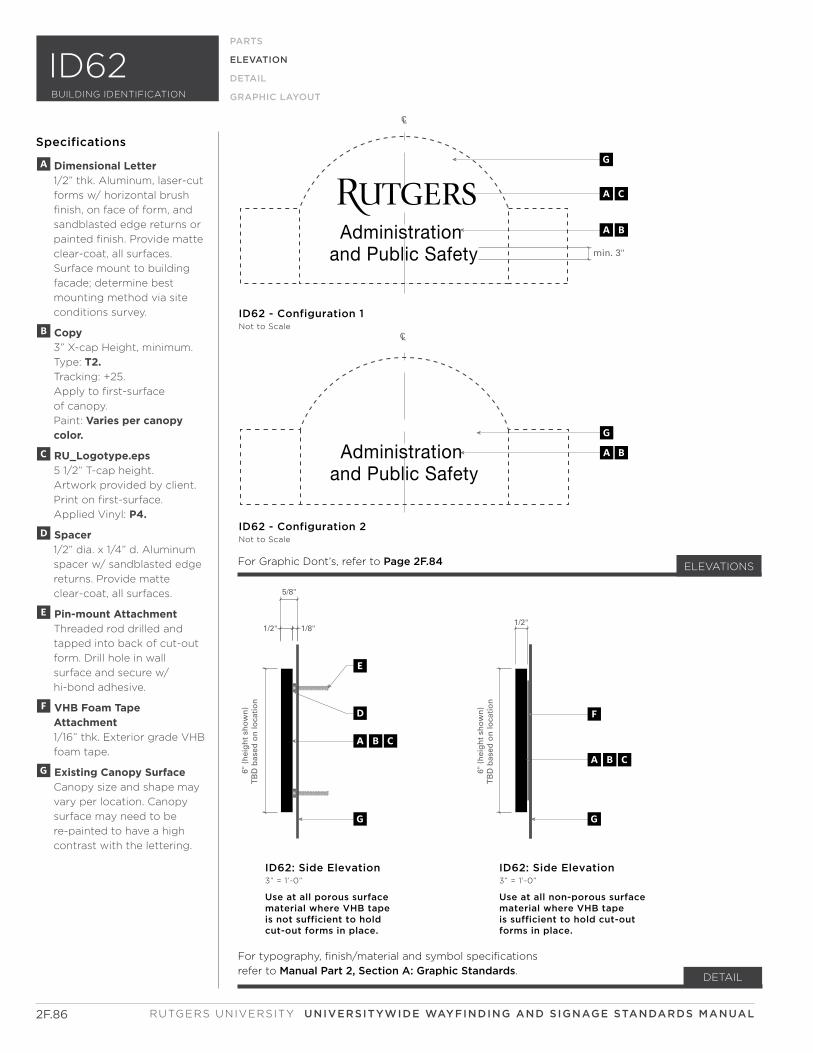
Administration and Public Safety
Administration and Public Safety
Administration and Public Safety
Administration and Public Safety min. 3"
G
A
AC
B
GAB
CL
CL
ID62 - Configuration 2Not to Scale
ID62 - Configuration 2Not to Scale
ID62 - Configuration 1Not to Scale
ID62 - Configuration 1Not to Scale
6" (
hei
gh
t sh
ow
n)
TB
D b
ased
on
loca
tio
n
6" (
hei
gh
t sh
ow
n)
TB
D b
ased
on
loca
tio
n
5/8"
1/8"1/2"1/2"
ID62: Side Elevation3” = 1’-0”
Use at all porous surface material where VHB tapeis not sufficient to hold cut-out forms in place.
ID62: Side Elevation3” = 1’-0”
Use at all non-porous surface material where VHB tapeis sufficient to hold cut-out forms in place.
ABC
ABCABC
ABC
F
GG
D
E
6" (
hei
gh
t sh
ow
n)
TB
D b
ased
on
loca
tio
n
6" (
hei
gh
t sh
ow
n)
TB
D b
ased
on
loca
tio
n
5/8"
1/8"1/2"1/2"
ID63: Side Elevation3” = 1’-0”
Use at all porous surface material where VHB tapeis not sufficient to hold cut-out forms in place.
ID63: Side Elevation3” = 1’-0”
Use at all non-porous surface material where VHB tapeis sufficient to hold cut-out forms in place.
F
GG
D
E
2F.86 RUTGERS UNIVERSITY UNIVERSITYWIDE WAYFINDING AND SIGNAGE STANDARDS MANUAL
DETAIL
BUILDING IDENTIFICATION
ID62PARTS
ELEVATION
DETAIL
GRAPHIC LAYOUT
Specifications
For typography, finish/material and symbol specifications
refer to Manual Part 2, Section A: Graphic Standards.
For Graphic Dont’s, refer to Page 2F.84 ELEVATIONS
A Dimensional Letter 1/2” thk. Aluminum, laser-cut
forms w/ horizontal brush
finish, on face of form, and
sandblasted edge returns or
painted finish. Provide matte
clear-coat, all surfaces.
Surface mount to building
facade; determine best
mounting method via site
conditions survey.
B Copy 3” X-cap Height, minimum.
Type: T2. Tracking: +25.
Apply to first-surface
of canopy.
Paint: Varies per canopy color.
c RU_Logotype.eps 5 1/2” T-cap height.
Artwork provided by client.
Print on first-surface.
Applied Vinyl: P4.
D Spacer 1/2” dia. x 1/4” d. Aluminum
spacer w/ sandblasted edge
returns. Provide matte
clear-coat, all surfaces.
E Pin-mount Attachment Threaded rod drilled and
tapped into back of cut-out
form. Drill hole in wall
surface and secure w/
hi-bond adhesive.
F VHB Foam Tape Attachment 1/16” thk. Exterior grade VHB
foam tape.
G Existing Canopy Surface Canopy size and shape may
vary per location. Canopy
surface may need to be
re-painted to have a high
contrast with the lettering.
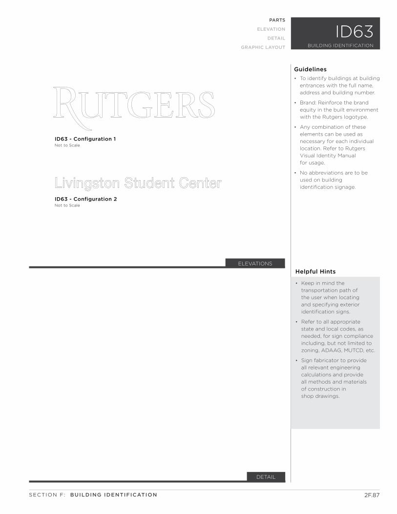
TB
D b
ased
on
loca
tio
n.
TB
D b
ased
on
loca
tio
n.
Existing canopy surface
Existing canopy surface
ID63 - Configuration 2Not to Scale
ID63 - Configuration 1Not to Scale
ID63 - Configuration 2Not to Scale
ID63 - Configuration 1Not to Scale
ID63 - Configuration 1Not to Scale
AC
AB
ELEVATIONS
2F.87
DETAIL
SECTION F: BUILDING IDENTIFICATION
BUILDING IDENTIFICATION
ID63
Guidelines
PARTS
ELEVATION
DETAIL
GRAPHIC LAYOUT
Helpful Hints
• Keep in mind the
transportation path of
the user when locating
and specifying exterior
identification signs.
• Refer to all appropriate
state and local codes, as
needed, for sign compliance
including, but not limited to
zoning, ADAAG, MUTCD, etc.
• Sign fabricator to provide
all relevant engineering
calculations and provide
all methods and materials
of construction in
shop drawings.
• To identify buildings at building
entrances with the full name,
address and building number.
• Brand: Reinforce the brand
equity in the built environment
with the Rutgers logotype.
• Any combination of these
elements can be used as
necessary for each individual
location. Refer to Rutgers
Visual Identity Manual
for usage.
• No abbreviations are to be
used on building
identification signage.
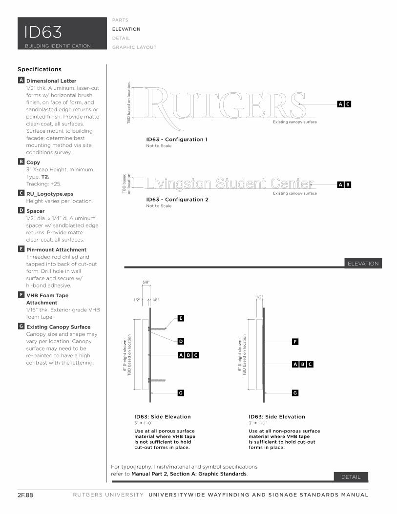
ELEVATION
TB
D b
ased
on
loca
tio
n.
TB
D b
ased
on
loca
tio
n.
Existing canopy surface
Existing canopy surface
ID63 - Configuration 2Not to Scale
ID63 - Configuration 1Not to Scale
ID63 - Configuration 2Not to Scale
ID63 - Configuration 1Not to Scale
ID63 - Configuration 1Not to Scale
AC
AB
2F.882F.88
PARTS
ELEVATION
DETAIL
GRAPHIC LAYOUT
Specifications
For typography, finish/material and symbol specifications
refer to Manual Part 2, Section A: Graphic Standards.DETAIL
6" (
hei
gh
t sh
ow
n)
TB
D b
ased
on
loca
tio
n
6" (
hei
gh
t sh
ow
n)
TB
D b
ased
on
loca
tio
n
5/8"
1/8"1/2"1/2"
ID62: Side Elevation3” = 1’-0”
Use at all porous surface material where VHB tapeis not sufficient to hold cut-out forms in place.
ID62: Side Elevation3” = 1’-0”
Use at all non-porous surface material where VHB tapeis sufficient to hold cut-out forms in place.
ABC
ABCABC
ABC
F
GG
D
E6"
(h
eig
ht
sho
wn
)T
BD
bas
ed o
n lo
cati
on
6" (
hei
gh
t sh
ow
n)
TB
D b
ased
on
loca
tio
n
5/8"
1/8"1/2"1/2"
ID63: Side Elevation3” = 1’-0”
Use at all porous surface material where VHB tapeis not sufficient to hold cut-out forms in place.
ID63: Side Elevation3” = 1’-0”
Use at all non-porous surface material where VHB tapeis sufficient to hold cut-out forms in place.
F
GG
D
E
A Dimensional Letter 1/2” thk. Aluminum, laser-cut
forms w/ horizontal brush
finish, on face of form, and
sandblasted edge returns or
painted finish. Provide matte
clear-coat, all surfaces.
Surface mount to building
facade; determine best
mounting method via site
conditions survey.
B Copy 3” X-cap Height, minimum.
Type: T2. Tracking: +25.
C RU_Logotype.eps Height varies per location.
D Spacer 1/2” dia. x 1/4” d. Aluminum
spacer w/ sandblasted edge
returns. Provide matte
clear-coat, all surfaces.
E Pin-mount Attachment Threaded rod drilled and
tapped into back of cut-out
form. Drill hole in wall
surface and secure w/
hi-bond adhesive.
F VHB Foam Tape Attachment 1/16” thk. Exterior grade VHB
foam tape.
G Existing Canopy Surface Canopy size and shape may
vary per location. Canopy
surface may need to be
re-painted to have a high
contrast with the lettering.
RUTGERS UNIVERSITY UNIVERSITYWIDE WAYFINDING AND SIGNAGE STANDARDS MANUAL
BUILDING IDENTIFICATION
ID63
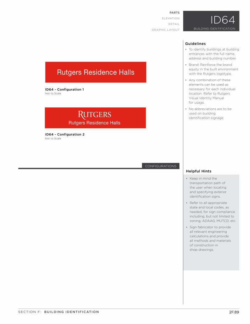
Rutgers Residence Halls
Rutgers Residence Halls
Rutgers Residence Halls
Rutgers Residence Halls
TB
D b
ased
on
loca
tio
nT
BD
bas
ed o
n lo
cati
on
ID64 - Configuration 2Not to Scale
ID64 - Configuration 1Not to Scale
ID64 - Front Elevation (Alternative Graphic)Not to Scale
ID64 - Front ElevationNot to Scale
A
A
BC
B
min. 3"
Helpful Hints
• Keep in mind the
transportation path of
the user when locating
and specifying exterior
identification signs.
• Refer to all appropriate
state and local codes, as
needed, for sign compliance
including, but not limited to
zoning, ADAAG, MUTCD, etc.
• Sign fabricator to provide
all relevant engineering
calculations and provide
all methods and materials
of construction in
shop drawings.
• To identify buildings at building
entrances with the full name,
address and building number.
• Brand: Reinforce the brand
equity in the built environment
with the Rutgers logotype.
• Any combination of these
elements can be used as
necessary for each individual
location. Refer to Rutgers
Visual Identity Manual
for usage.
• No abbreviations are to be
used on building
identification signage.
CONFIGURATIONS
2F.892F.89
Guidelines
PARTS
ELEVATION
DETAIL
GRAPHIC LAYOUT
SECTION F: BUILDING IDENTIFICATION
BUILDING IDENTIFICATION
ID64
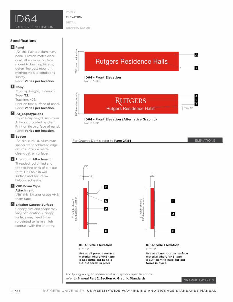
Rutgers Residence Halls
Rutgers Residence Halls
Rutgers Residence Halls
Rutgers Residence Halls
TB
D b
ased
on
loca
tio
nT
BD
bas
ed o
n lo
cati
on
ID64 - Configuration 2Not to Scale
ID64 - Configuration 1Not to Scale
ID64 - Front Elevation (Alternative Graphic)Not to Scale
ID64 - Front ElevationNot to Scale
A
A
BC
B
min. 3"
ELEVATIONS
2F.90
ELEVATION
PARTS
ELEVATION
DETAIL
GRAPHIC LAYOUT
Specifications
For typography, finish/material and symbol specifications
refer to Manual Part 2, Section A: Graphic Standards.
2F.90
GRAPHIC LAYOUTS
6" (
hei
gh
t sh
ow
n)
TB
D b
ased
on
loca
tio
n
6" (
hei
gh
t sh
ow
n)
TB
D b
ased
on
loca
tio
n
5/8"
1/8"1/2"1/2"
ID64: Side Elevation3” = 1’-0”
Use at all porous surface material where VHB tapeis not sufficient to hold cut-out forms in place.
ID64: Side Elevation3” = 1’-0”
Use at all non-porous surface material where VHB tapeis sufficient to hold cut-out forms in place.
AA
F
GG
D
E
A Panel 1/2” thk. Painted aluminum,
panel. Provide matte clear-
coat, all surfaces. Surface
mount to building facade;
determine best mounting
method via site conditions
survey.
Paint: Varies per location.
B Copy 3” X-cap Height, minimum.
Type: T2. Tracking: +25.
Print on first-surface of panel.
Paint: Varies per location.
C RU_Logotype.eps 5 1/2” T-cap height, minimum.
Artwork provided by client.
Print on first-surface of panel.
Paint: Varies per location.
D Spacer 1/2” dia. x 1/4” d. Aluminum
spacer w/ sandblasted edge
returns. Provide matte
clear-coat, all surfaces.
E Pin-mount Attachment Threaded rod drilled and
tapped into back of cut-out
form. Drill hole in wall
surface and secure w/
hi-bond adhesive.
F VHB Foam Tape Attachment 1/16” thk. Exterior grade VHB
foam tape.
G Existing Canopy Surface Canopy size and shape may
vary per location. Canopy
surface may need to be
re-painted to have a high
contrast with the lettering.
For Graphic Dont’s, refer to Page 2F.84
RUTGERS UNIVERSITY UNIVERSITYWIDE WAYFINDING AND SIGNAGE STANDARDS MANUAL
BUILDING IDENTIFICATION
ID64