Embed Size (px)
Citation preview
11-01-16
SECTION 27 11 00COMMUNICATIONS EQUIPMENT ROOM FITTINGS
SPEC WRITER NOTES:1. Use this section only for NCA projects. Delete text between // ______ // not applicable to project. Edit remaining text to suit project.2. Contact Department of Veterans Affairs’ (VA) AHJ, Spectrum Management and COMSEC Service (SMCS), Special Communications Team (SMCS 07A2), Telephone (202-461-5301/5311), for technical assistance.3. When using this section, always include Section 27 05 00, COMMON WORK RESULTS FOR COMMUNICATIONS in project specifications.
PART 1 - GENERAL
1.1 SUMMARYA. Section Includes:
1. Voice and Digital TIP Cable Distribution System including, but not
be limited to, equipment cabinets, interface enclosures, and relay
racks, necessary combiners, traps, and filters, and necessary
passive devices such as splitters, couplers, cable “patch”, “punch
down”, and cross-connector blocks or devices, voice and data
distribution sub-systems, and associated hardware.
2. System includes, but is not limited to, telecommunication rooms
(TR), telecommunications outlets (TCO), copper and fiber
optic // , and analog radio frequency (RF) Emergency TIP Systems
coaxial // distribution cables, connectors, “patch” cables, and
“break out” devices.
B. See Section 27 05 00, COMMON WORK RESULTS FOR COMMUNICATIONS for
requirements governing work of this section.
1.2 RELATED REQUIREMENTSA. General electrical requirements and items common to more than one
Division 27 section: Section 27 05 00, COMMON WORK RESULTS FOR
COMMUNICATIONS.
B. Electrical Components: Section 27 05 33, RACEWAYS AND BOXES FOR
COMMUNICATIONS SYSTEMS.
C. Labeling: Section 27 10 00, STRUCTURED CABLING.
1.3 APPLICABLE PUBLICATIONSA. Comply with references to extent specified in this section.
COMMUNICATIONS EQUIPMENT ROOM FITTINGSSECTION 27 11 00 - 1
11-01-16
B. National Fire Protection Association (NFPA):
1. 70-17 - National Electrical Code.
C. Federal Communications Commission (FCC) Publications: Standards
for telephone equipment and systems.
1.4 SUBMITTALSA. Submittal Procedures: Section 01 33 23, SHOP DRAWINGS, PRODUCT DATA, AND
SAMPLES.
B. Submittal Drawings:
1. Pictorial layouts of each MTC, IMTC, and RTCs; MCCS, IMCCS, VCCS,
and HCCS termination cabinets, each distribution cabinet layout
drawing, and TCO as each is installed and configured.
2. Engineering drawings, showing calculated signal levels at EPBX
output, each input and output distribution point, proposed TCO
values, and signal level at each TCO multipin, fiber optic, // , and
coaxial cable // jack.
C. Environmental Requirements: Confirm environmental specifications for
physical telecommunications areas. Identify requirements for initial and
expanded system configurations for the following:
1. Floor loading for batteries and cabinets.
2. Minimum floor space and ceiling heights.
3. Minimum door size for equipment passage.
4. Power requirements: Voltage, amperage, phases, and circuit
quantities required.
5. Air conditioning, heating, and humidity requirements, including
ambient temperature and relative humidity operating ranges required
to prevent equipment damage.
6. Air conditioning requirements expressed in BTU per hour, based on
adequate dissipation of generated heat to maintain required room and
equipment standards.
7. Proposed floor plan, based on expanded system configuration of
proposed EPBX for this FACILITY.
8. Conduit size requirement among main TR, computer, and console rooms.
9. Main trunk line and riser pathways, cable duct, and conduit
requirements between each MTC, TR, and TCO.
D. System Narrative Description:
1. List equipment to be provided, (a.k.a. Bill of Materials (BOM))
including quantity, manufacturer, and model number of each item. The
following is minimum equipment required by system:
COMMUNICATIONS EQUIPMENT ROOM FITTINGSSECTION 27 11 00 - 2
11-01-16
SPEC WRITER NOTE: Select required equipment items quantities that will satisfy system needs and edit between // - //. Add equipment required, but not listed. List equipment items not required, mark "not required" and renumber section.
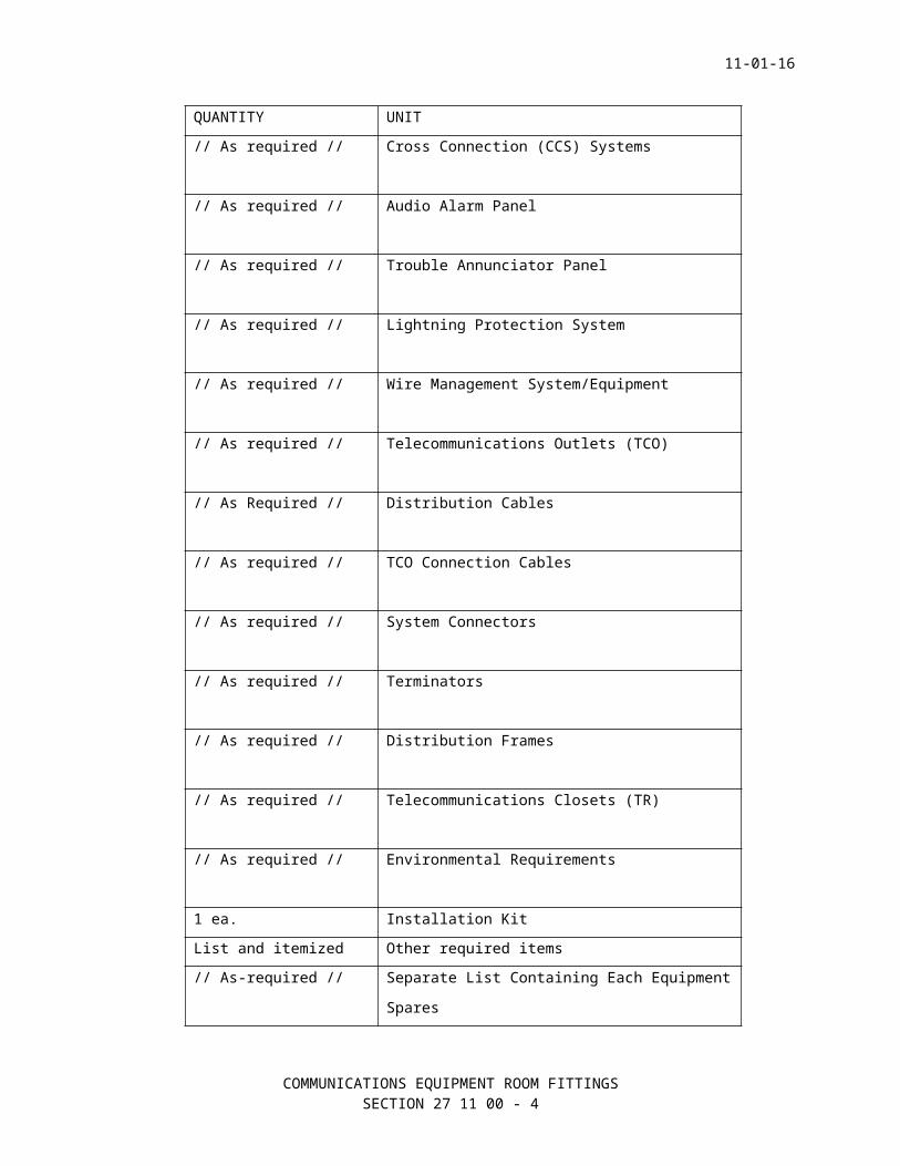
QUANTITY UNIT
// As required // Cabinet Assemblies
// As required // Environmental Cabinet
// As required // Distribution/Interface Cabinet
// As required // Equipment (Radio Relay) Rack
// As required // Cross Connection (CCS) Systems
// As required // Audio Alarm Panel
// As required // Trouble Annunciator Panel
// As required // Lightning Protection System
// As required // Wire Management System/Equipment
// As required // Telecommunications Outlets (TCO)
// As Required // Distribution Cables
// As required // TCO Connection Cables
// As required // System Connectors
// As required // Terminators
// As required // Distribution Frames
COMMUNICATIONS EQUIPMENT ROOM FITTINGSSECTION 27 11 00 - 3
11-01-16
QUANTITY UNIT
// As required // Telecommunications Closets (TR)
// As required // Environmental Requirements
1 ea. Installation Kit
List and itemized Other required items
// As-required // Separate List Containing Each Equipment
Spares
E. Test Equipment List:
1. Provide test equipment required to test system according to
parameters specified. Unless otherwise stated, test equipment is not
considered part of system. Provide test equipment of accuracy better
than parameters to be tested.
2. Test equipment includes calibration tag of acceptable calibration
service dated maximum 12 months before test. Minimum submittal
includes manufacturer and model number of the following equipment:
a. Spectrum Analyzer.
b. Signal Level Meter.
c. Volt-Ohm Meter.
d. Time Domain Reflectometer (TDR) with strip chart recorder (Data
and Optical Measuring).
e. Bit Error Test Set (BERT).
f. Camera, minimum 60 pictures, develop immediately to include
appropriate test equipment adapters. Video camera in VHS format
is acceptable alternative.
g. // Video Waveform Monitor //.
h. // Video Vector Scope //.
i. // Color Video Monitor with audio capability //.
j. // 100 MHz Oscilloscope with video adapters //.
F. Samples:
SPEC WRITER NOTES: See TDM, Section 3 for TCO Wall Outlet requirements.
1. TCO Wall Outlet:
2. Data CCS patch panel, punch block or connection device with RJ45
connectors installed.
COMMUNICATIONS EQUIPMENT ROOM FITTINGSSECTION 27 11 00 - 4
11-01-16
3. Telephone CCS system with IDC and RJ45 connectors and cable terminal
equipment installed.
4. Fiber optic CCS patch panel or breakout box with cable management
equipment and “ST” connectors installed.
5. 610 mm (2 ft.) section of each copper cable with cable sweep tags
and connectors installed.
6. // 610 mm (2 ft.) section of each fiber optic cable with cable sweep
tags and connectors installed //.
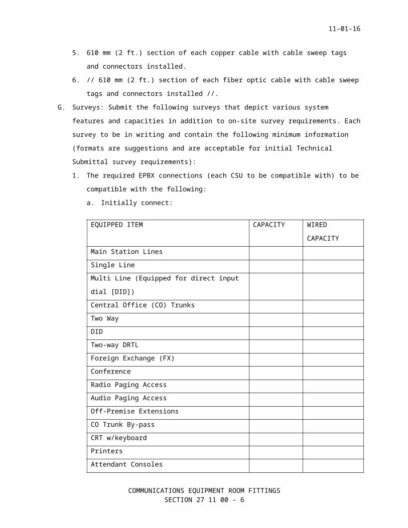
G. Surveys: Submit the following surveys that depict various system
features and capacities in addition to on-site survey requirements. Each
survey to be in writing and contain the following minimum information
(formats are suggestions and are acceptable for initial Technical
Submittal survey requirements):
1. The required EPBX connections (each CSU to be compatible with) to be
compatible with the following:
a. Initially connect:
EQUIPPED ITEM CAPACITY WIRED
CAPACITY
Main Station Lines
Single Line
Multi Line (Equipped for direct input
dial [DID])
Central Office (CO) Trunks
Two Way
DID
Two-way DRTL
Foreign Exchange (FX)
Conference
Radio Paging Access
Audio Paging Access
Off-Premise Extensions
CO Trunk By-pass
CRT w/keyboard
Printers
Attendant Consoles
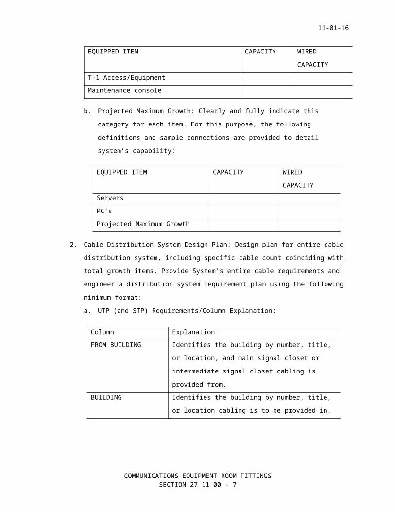
T-1 Access/Equipment
COMMUNICATIONS EQUIPMENT ROOM FITTINGSSECTION 27 11 00 - 5
11-01-16
EQUIPPED ITEM CAPACITY WIRED
CAPACITY
Maintenance console
b. Projected Maximum Growth: Clearly and fully indicate this
category for each item. For this purpose, the following
definitions and sample connections are provided to detail
system’s capability:
EQUIPPED ITEM CAPACITY WIRED
CAPACITY
Servers
PC’s
Projected Maximum Growth
2. Cable Distribution System Design Plan: Design plan for entire cable
distribution system, including specific cable count coinciding with
total growth items. Provide System's entire cable requirements and
engineer a distribution system requirement plan using the following
minimum format:
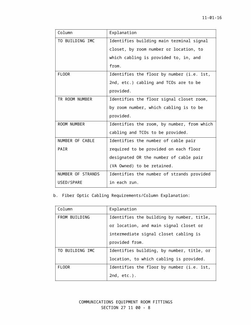
a. UTP (and STP) Requirements/Column Explanation:
Column Explanation
FROM BUILDING Identifies the building by number, title,
or location, and main signal closet or
intermediate signal closet cabling is
provided from.
BUILDING Identifies the building by number, title,
or location cabling is to be provided in.
TO BUILDING IMC Identifies building main terminal signal
closet, by room number or location, to
which cabling is provided to, in, and
from.
FLOOR Identifies the floor by number (i.e. 1st,
2nd, etc.) cabling and TCOs are to be
provided.
COMMUNICATIONS EQUIPMENT ROOM FITTINGSSECTION 27 11 00 - 6
11-01-16
Column Explanation
TR ROOM NUMBER Identifies the floor signal closet room,
by room number, which cabling is to be
provided.
ROOM NUMBER Identifies the room, by number, from which
cabling and TCOs to be provided.
NUMBER OF CABLE
PAIR
Identifies the number of cable pair
required to be provided on each floor
designated OR the number of cable pair
(VA Owned) to be retained.
NUMBER OF STRANDS
USED/SPARE
Identifies the number of strands provided
in each run.
b. Fiber Optic Cabling Requirements/Column Explanation:
Column Explanation
FROM BUILDING Identifies the building by number, title,
or location, and main signal closet or
intermediate signal closet cabling is
provided from.
TO BUILDING IMC Identifies building, by number, title, or
location, to which cabling is provided.
FLOOR Identifies the floor by number (i.e. 1st,
2nd, etc.).
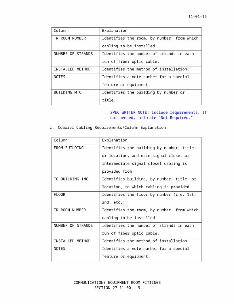
TR ROOM NUMBER Identifies the room, by number, from which
cabling to be installed.
NUMBER OF STRANDS Identifies the number of strands in each
run of fiber optic cable.
INSTALLED METHOD Identifies the method of installation.
NOTES Identifies a note number for a special
feature or equipment.
BUILDING MTC Identifies the building by number or
title.
SPEC WRITER NOTE: Include requirements. If not needed, indicate "Not Required."
c. Coaxial Cabling Requirements/Column Explanation:
COMMUNICATIONS EQUIPMENT ROOM FITTINGSSECTION 27 11 00 - 7
11-01-16
Column Explanation
FROM BUILDING Identifies the building by number, title,
or location, and main signal closet or
intermediate signal closet cabling is
provided from.
TO BUILDING IMC Identifies building, by number, title, or
location, to which cabling is provided.
FLOOR Identifies the floor by number (i.e. 1st,
2nd, etc.).
TR ROOM NUMBER Identifies the room, by number, from which
cabling to be installed.
NUMBER OF STRANDS Identifies the number of strands in each
run of fiber optic cable.
INSTALLED METHOD Identifies the method of installation.
NOTES Identifies a note number for a special
feature or equipment.
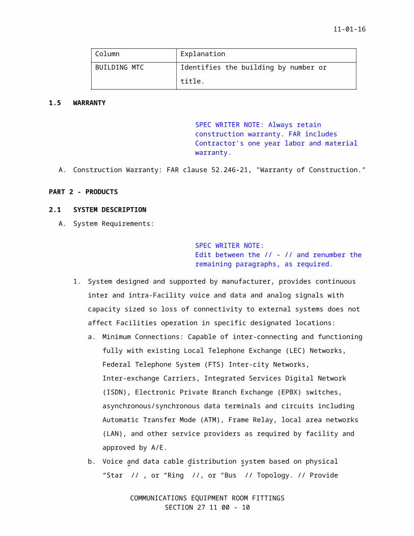
BUILDING MTC Identifies the building by number or
title.
1.5 WARRANTY
SPEC WRITER NOTE: Always retain construction warranty. FAR includes Contractor's one year labor and material warranty.
A. Construction Warranty: FAR clause 52.246-21, "Warranty of Construction."
PART 2 - PRODUCTS
2.1 SYSTEM DESCRIPTIONA. System Requirements:
SPEC WRITER NOTE:Edit between the // - // and renumber the remaining paragraphs, as required.
1. System designed and supported by manufacturer, provides continuous
inter and intra-Facility voice and data and analog signals with
capacity sized so loss of connectivity to external systems does not
affect Facilities operation in specific designated locations:
COMMUNICATIONS EQUIPMENT ROOM FITTINGSSECTION 27 11 00 - 8
11-01-16
a. Minimum Connections: Capable of inter-connecting and functioning
fully with existing Local Telephone Exchange (LEC) Networks,
Federal Telephone System (FTS) Inter-city Networks,
Inter-exchange Carriers, Integrated Services Digital Network
(ISDN), Electronic Private Branch Exchange (EPBX) switches,
asynchronous/synchronous data terminals and circuits including
Automatic Transfer Mode (ATM), Frame Relay, local area networks
(LAN), and other service providers as required by facility and
approved by A/E.
b. Voice and data cable distribution system based on physical
“Star” // , or “Ring” //, or “Bus” // Topology. // Provide
Analog RF coaxial cable distribution system in “home run”
configuration from each associated riser TR to identified
locations and as shown on drawings. //
c. Compatible with and able to provide direct digital connection to
trunk level equipment including, but not limited to, directly
accessing trunk level equipment including the telephone system,
audio paging, Industry Standard “T” and “DS” carrier services
and external protocol converters. Also include connections to
“T” and “DS” access/equipment or Customer Service Units (CSU)
used in FTS and other trunk applications. Provide T-1
access/equipment (or CSU), as required for use, in FTS and other
trunk applications by system design when this equipment is not
included in existing telephone system and will be deactivated by
the installation of the System. Provide T-1 equipment required
to terminate and operate the quantity of circuits designated.
Connect CSU's to System’s emergency battery power supply. System
to be fully capable of operating in Industry Standard “DS”
protocol and provide protocol service when required.
2. Minimum Subsystem Requirements: Independent sub-systems comprise of
complete and functional voice and digital telecommunications cabling
system: “Main” (MTC), “intermediate” (IMTC), and “riser” (RTC) TR’s;
“vertical” (or “riser”) trunk cabling system; vertical
cross-connection (VCC) cabling systems, and TCO’s with minimum three
(3) RJ-45 jacks for appropriate telephone, Data connections, and
additional jacks, connectors, drop and patch cords, terminators, and
adapters provided:
a. Telecommunication Toom (TR):
COMMUNICATIONS EQUIPMENT ROOM FITTINGSSECTION 27 11 00 - 9
11-01-16
1) Minimum one for MTC, each building IMTC, and each RTC per
building floor location. Provide additional TR’s in large
buildings, where horizontal distance to farthest voice and
digital work area exceeds 90 m (295 feet). Maximum DC
resistance per cable pair, 28.6 Ohms per 305 m (1,000 feet).
Centrally locate each TR to cover maximum amount of local
floor space. TR’s house in cabinets or enclosures, on relay
racks, and on backboards, various telecommunication data
equipment, controllers, multiplexers, bridges, routers, LAN
hubs, telephone cross-connecting, active and passive
equipment.
2) TR’s may house fire alarm, video, public address, radio
entertainment, intercom, and radio paging equipment.
Regardless of method of installation, terminate mounting,
termination, or cross-connecting used, vertical copper and
fiber optic // and analog RF coaxial // cables on appropriate
cross-connection systems (CCS) containing patch panels, punch
blocks, // and // or // breakout devices provided in
enclosures and tested. cable or wire management system to be
a part of each CCS.
a) Provide minimum three 110-120 Volt AC active quad
outlets, each with “U” grounded receptacles at minimum of
one outlet for each front, side and back wall. For larger
building TR applications, provide minimum one additional
quad AC outlet for every 800 sq. m (8,000 sq. ft.) of
useable floor space. Equally space additional outlets
along the wall.
b) Provide climate control in each TR 24 hours a day, seven
days per week and 52 week per year to prevent failure of
electronic components and for mission critical functional
applications. Contracting Officer's Representative (COR)
will provide minimum climate control
requirements. // Provide minimum two individual and
properly sized self-contained climate controlled
equipment cabinet enclosures; one designated for
voice, // and // one designated for data service, in each
TR location identified on drawings and determined by COR,
COMMUNICATIONS EQUIPMENT ROOM FITTINGSSECTION 27 11 00 - 10
11-01-16
in lieu of providing additional required TR air handling
capability. //.
2.2 SYSTEM PERFORMANCE
SPEC WRITER NOTE: The use of Category 6 must be specifically approved during project design due to increased project cost.
A. Minimum System support for the following voice and data // and analog
RF // operations for minimum Category 5e // 6 // Certified
Telecommunication Service:
1. Interchange (or interface) capabilities:
a. Basic Rate (BRI).
b. Primary Rate (PRI).
2. ISDN measured at // ______ //:
a. Narrow Band BRI:
1) B Channel: 64 kilo-Bits per second (kBps), minimum.
2) D Channel: 16 kBps, minimum.
3) H Channel: 384 kBps, minimum.
b. Narrow Band PRI:
1) B Channel: 64 kBps, minimum.
2) D Channel: 64 kBps, minimum.
3) H Channel: 1,920 kBps, minimum.
c. Wide (or Broad) Band Channels: 140 mega (m)-Bps, minimum,
capable to 565 mBps at “T” reference.
3. ATM operation and interface: ATM 155 mBps measured
at // ____________. //
4. Frame Relay: Stated compliances measured at // ____________. //
5. Integrated Data Communications Utility (IDCU) operation and
interface: Measured at // ____________. //
6. Government Open Systems Interconnection Profile (GOSSIP) compliant:
Measured at // ____________. //
7. Fiber optic Distributed Data Interface (FDDI): Minimum 100 mBps to
maximum 1.8 giga(g)-Bps data bit stream speed measured
at // ____________ // (to be Synchronous Optical Network [SONET]
compliant).
8. // Coaxial Distribution, provide specific approved information
here. //
9. // RF Distribution, provide specific approved information here. //
COMMUNICATIONS EQUIPMENT ROOM FITTINGSSECTION 27 11 00 - 11
11-01-16
10. System Sensitivity: Provide satisfactory service for minimum 915 m
(3,000 feet) for each voice and data // and analog RF // location.
11. // Other ____________. //
B. Minimum System support for the following operating parameters:
1. EPBX connection:
a. System speed: Minimum 1.0 gBps per second.
b. Impedance: 600 Ohms.
c. Cross Modulation: -60 deci-Bel (dB).
d. Hum Modulation: -55 dB.
e. System data error: Minimum 10 to the -10 Bps.
f. Loss: Measured at frame output with reference Zero (0) decibel
measured (dBm) at 1,000 Hertz (Hz) applied to frame input.
1) Trunk to station: Maximum 1.5 dB.
2) Station to station: Maximum 3.0 dB.
3) Internal switch crosstalk: -60 dB when signal of + 10 decibel
measured (dBm), 500-2,500 Hz range is applied to primary
path.
4) Idle channel noise: 25 dBm “C” or 3.0 dBm “O” above reference
(terminated) ground noise, whichever is greater.
5) Traffic Grade of Service for Voice and Data:
6) Minimum service grade of P-01 with average traffic load of
7.0 CCS per station per hour and traffic overload in data
circuits will not interfere with, nor degrade, voice service.
7) Average CCS per voice station: Maintain average CCS capacity
per voice station at 7.0 CCS when EPBX is expanded up to
projected maximum growth as stated herein.
SPEC WRITER NOTE: Verify with A/E for required information.
2. Coaxial Connection:
SPEC WRITER NOTE: Verify with A/E for required information.
3. RF Connection:
4. Telecommunications Outlet (TCO):
COMMUNICATIONS EQUIPMENT ROOM FITTINGSSECTION 27 11 00 - 12
11-01-16
SPEC WRITER NOTE: Confirm each characteristics with TDM, Section 3 Guidelines.
a. Voice:
1) Isolation (outlet-outlet): 24 dB.
2) Impedance: 600 Ohms, balanced (BAL).
3) Signal Level: 0 decibel per mili-Volt (dBmV) + 0.1 dBmV.
4) System speed: Minimum 100 mBps.
5) System data error: Minimum 10 to the -6 Bps.
b. Data:
1) Isolation (outlet-outlet): 24 dB.
2) Impedance: 600 Ohms, BAL.
3) Signal Level: 0 dBmV + 0.1 dBmV.
4) System speed: Minimum 120 mBps.
5) System data error: Minimum 10 to the -8 Bps.
c. Fiber optic:
1) Isolation (outlet-outlet): 36 dB.
2) Signal Level: 0 dBmV + 0.1 dBmV.
3) System speed: Minimum 540 mBps.
4) System data error: Minimum 10 to the -6 bps.
2.3 PRODUCTS - GENERALA. Provide system components from one manufacturer.
1. Equipment: New and manufacturer's current model of standard
products, meet or exceed specifications.
2. Provide proper size and type of cable duct and conduit and wiring.
3. Provide interfacing cable connections for telephone, // PA //, //
Radio Paging, // // and __________ // systems with System.
4. Telephone equipment and // PA interface equipment // Radio interface
equipment // to be interface points for connection of // PA //
Radio // interface cabling from telephone switch via system
telephone interface unit.
5. Active Electronic Component Equipment: Solid state components, rated
for continuous duty service, and comply with FCC standards for
telephone equipment, systems, and service.
6. Passive Distribution Equipment: Meet or exceed minus 80 dB radiation
shielding specifications.
7. Telephone Cable Systems without Adapters: Terminate interconnecting
twisted pair, fiber-optic // or coaxial // cables on equipment
COMMUNICATIONS EQUIPMENT ROOM FITTINGSSECTION 27 11 00 - 13
11-01-16
terminal boards, punch blocks, breakout boxes, splice blocks, and
unused equipment ports/taps according to manufacturer's
instructions. Do not leave unused or spare cable unterminated,
unconnected, loose or unsecured.
8. Color Code Distribution Wiring: Conform to Telephone Industry
standard, EIA/TIA, and this specification, whichever is most
stringent. Legibly and permanently label equipment, cable duct and
conduit, enclosures, wiring, terminals, and cables, as shown on
record drawings, to facilitate installation and maintenance. Refer
to Section 27 10 00, STRUCTURED CABLING.
9. Connectors:
a. Plug-in Connectors: Connect equipment, except coaxial cables and
interface points. Coaxial cable distribution points and RF
transmission lines to use coaxial cable connections recommended
by cable manufacturer and approved by System manufacturer.
b. Barrier Terminal Screw Type Connectors: Use Base- band cable
systems, at a minimum.
c. Acceptable Alternative:
1) Crimp Type Connectors: Installed with ratchet type
installation tool, as long as cable dress, pairs, shielding,
grounding, and connections and labeling are provided same as
barrier terminal strip connectors. No tape, wire nuts, or
solder type connections are permitted.
10. Equipment Faceplates: Stainless steel, anodized aluminum, or
UL approved cycolac plastic.
11. Provide noise filters and surge protectors for each equipment
interface cabinet, switch equipment cabinet, control console, local,
and remote active equipment locations.
SPEC WRITER NOTES: Use non-detectable type at cemeteries only.
12. Underground Warning Tape: Standard, 0.1 mm (4 mil polyethylene),
76 mm (3 inch) wide non-detectable type, color as follows:
a. Red with black letters imprinted “CAUTION BURIED ELECTRIC LINE
BELOW”.
b. Orange with black letters imprinted “CAUTION BURIED TELEPHONE
LINE BELOW”.
COMMUNICATIONS EQUIPMENT ROOM FITTINGSSECTION 27 11 00 - 14
11-01-16
c. Orange with black letters imprinted “CAUTION BURIED FIBER OPTIC
LINE BELOW”.
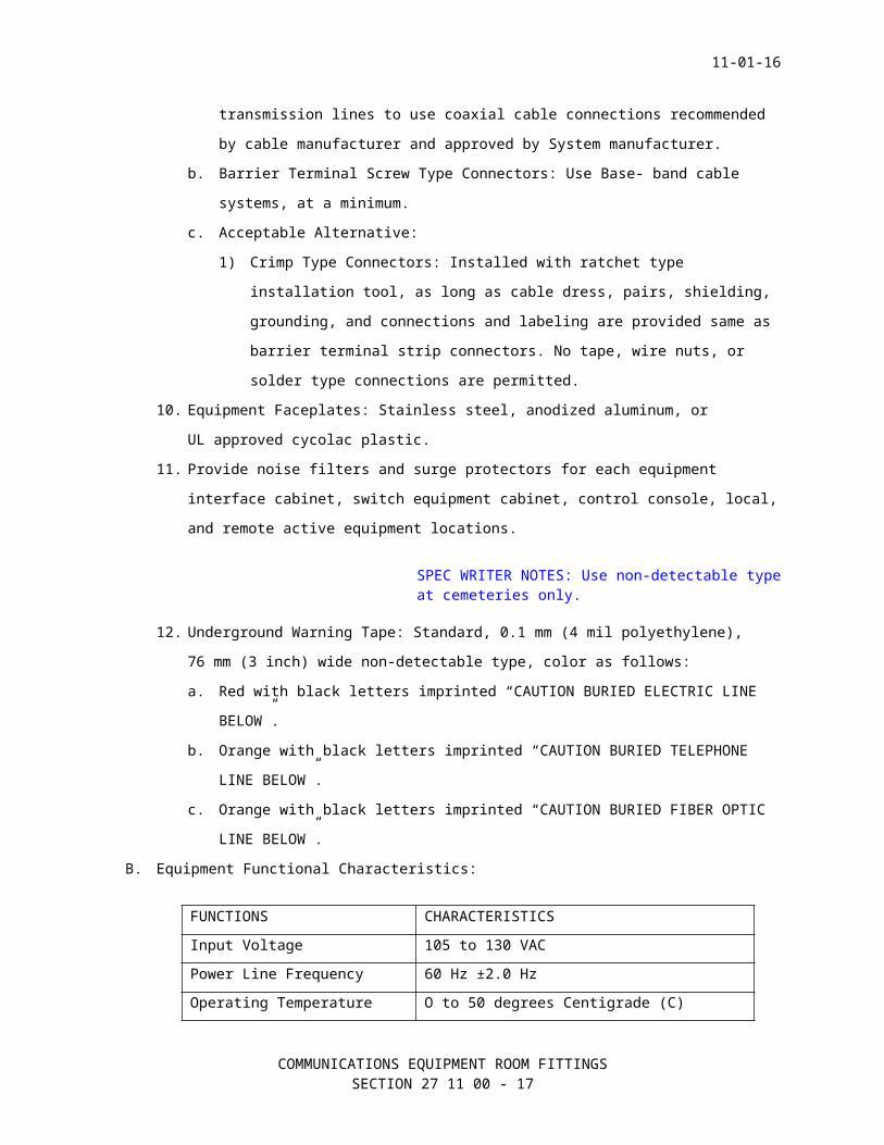
B. Equipment Functional Characteristics:
FUNCTIONS CHARACTERISTICS
Input Voltage 105 to 130 VAC
Power Line Frequency 60 Hz ±2.0 Hz
Operating Temperature O to 50 degrees Centigrade (C)
Humidity 80 percent minimum rating
C. Equipment Standards and Testing:
1. Supplies and materials, listed, labeled or certified by UL or a
nationally recognized testing laboratory. Refer to Section 27 05 00,
COMMON WORK RESULTS FOR COMMUNICATIONS.
2. Active and passive equipment required by System design and approved
technical submittal, comply with each UL standard bearing UL seal in
effect as of technical submittal date (or date when COR approved
system equipment necessary to be replaced) was technically reviewed
and approved by VA.
3. NRTL listed with seal or seal of testing laboratory that warrants
complicity with required NRTL Standards.
2.4 EQUIPMENTA. Cabinet with Internal Equipment Mounting Rack: Refer to Section27 05 00
COMMON WORK RESULTS FOR COMMUNICATIONS.
B. Cross-Connection System (CCS) Equipment Breakout, Termination Connector
(or Bulkhead), and Patch Panels:
1. Connector Panels: Solid aluminum, custom designed, flat smooth,
3.175 mm (1/8 inches) thick,. Mount bulkhead equipment connectors on
panel to connect cabinet equipment’s signal, control, and coaxial
cables through panel. Panel color to match cabinet installed.
a. Voice (or Telephone):
1) CSS, minimum Industry Standard type 110 punch blocks for
voice or telephone, and control wiring in lieu of patch
panels, certified for Category six service. IDC punch blocks
(with internal RJ45 jacks) are acceptable for use in CCS,
design for Category six telecommunications service; size and
type of UTP cable used as specified. Secure punch block
strips according to manufacturer-designed physical anchoring
COMMUNICATIONS EQUIPMENT ROOM FITTINGSSECTION 27 11 00 - 15
11-01-16
unit on wall location in MTC, IMTC, RTC, and TR. Console,
cabinet, rail, panel, etc. mounting is allowed according to
manufacturer's instructions and as approved by COR. Punch
blocks may not be used for Class II or 120 Volt AC power
wiring.
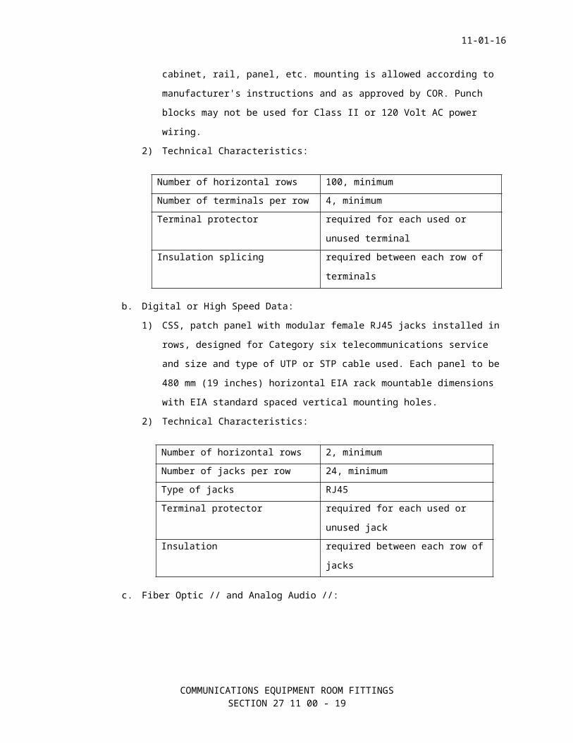
2) Technical Characteristics:
Number of horizontal rows 100, minimum
Number of terminals per row 4, minimum
Terminal protector required for each used or
unused terminal
Insulation splicing required between each row of
terminals
b. Digital or High Speed Data:
1) CSS, patch panel with modular female RJ45 jacks installed in
rows, designed for Category six telecommunications service
and size and type of UTP or STP cable used. Each panel to be
480 mm (19 inches) horizontal EIA rack mountable dimensions
with EIA standard spaced vertical mounting holes.
2) Technical Characteristics:
Number of horizontal rows 2, minimum
Number of jacks per row 24, minimum
Type of jacks RJ45
Terminal protector required for each used or
unused jack
Insulation required between each row of
jacks
c. Fiber Optic // and Analog Audio //:
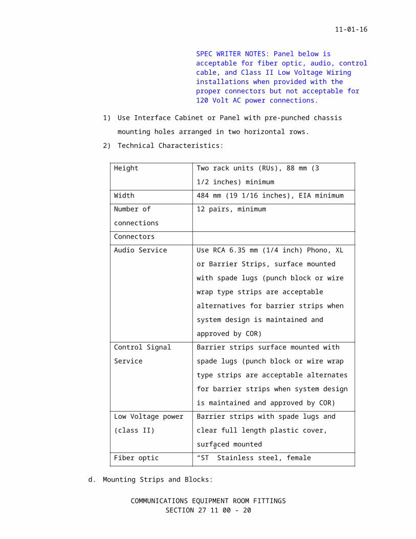
SPEC WRITER NOTES: Panel below is acceptable for fiber optic, audio, control cable, and Class II Low Voltage Wiring installations when provided with the proper connectors but not acceptable for 120 Volt AC power connections.
1) Use Interface Cabinet or Panel with pre-punched chassis
mounting holes arranged in two horizontal rows.
COMMUNICATIONS EQUIPMENT ROOM FITTINGSSECTION 27 11 00 - 16
11-01-16
2) Technical Characteristics:
Height Two rack units (RUs), 88 mm (3
1/2 inches) minimum
Width 484 mm (19 1/16 inches), EIA minimum
Number of
connections
12 pairs, minimum
Connectors
Audio Service Use RCA 6.35 mm (1/4 inch) Phono, XL
or Barrier Strips, surface mounted
with spade lugs (punch block or wire
wrap type strips are acceptable
alternatives for barrier strips when
system design is maintained and
approved by COR)
Control Signal
Service
Barrier strips surface mounted with
spade lugs (punch block or wire wrap
type strips are acceptable alternates
for barrier strips when system design
is maintained and approved by COR)
Low Voltage power
(class II)
Barrier strips with spade lugs and
clear full length plastic cover,
surfaced mounted
Fiber optic “ST” Stainless steel, female
d. Mounting Strips and Blocks:
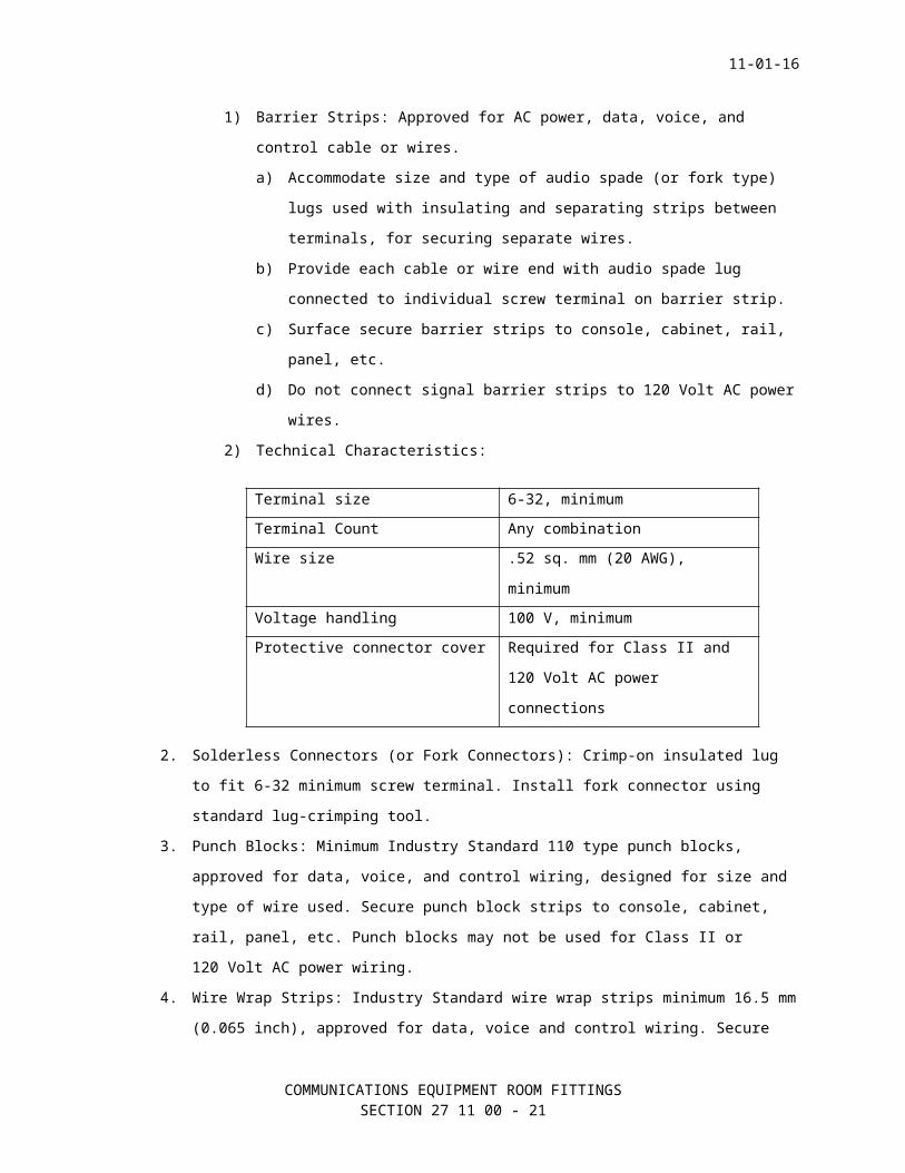
1) Barrier Strips: Approved for AC power, data, voice, and
control cable or wires.
a) Accommodate size and type of audio spade (or fork type)
lugs used with insulating and separating strips between
terminals, for securing separate wires.
b) Provide each cable or wire end with audio spade lug
connected to individual screw terminal on barrier strip.
c) Surface secure barrier strips to console, cabinet, rail,
panel, etc.
d) Do not connect signal barrier strips to 120 Volt AC power
wires.
2) Technical Characteristics:
COMMUNICATIONS EQUIPMENT ROOM FITTINGSSECTION 27 11 00 - 17
11-01-16
Terminal size 6-32, minimum
Terminal Count Any combination
Wire size .52 sq. mm (20 AWG),
minimum
Voltage handling 100 V, minimum
Protective connector cover Required for Class II and
120 Volt AC power
connections
2. Solderless Connectors (or Fork Connectors): Crimp-on insulated lug
to fit 6-32 minimum screw terminal. Install fork connector using
standard lug-crimping tool.
3. Punch Blocks: Minimum Industry Standard 110 type punch blocks,
approved for data, voice, and control wiring, designed for size and
type of wire used. Secure punch block strips to console, cabinet,
rail, panel, etc. Punch blocks may not be used for Class II or
120 Volt AC power wiring.
4. Wire Wrap Strips: Industry Standard wire wrap strips minimum 16.5 mm
(0.065 inch), approved for data, voice and control wiring. Secure
wire wrap strips to cabinet, rail, panel, etc. Wire wrap strips are
not acceptable for Class II or 120 Volt AC power wiring.
C. Wire Management System and Equipment:
1. Wire Management System: Management center of cable system, CCS, and
TR; performs as platform to house peripheral equipment in standard
relay rack or equipment cabinet. Install cables and connections at
rear of each system interface to IDC and patch panels, punch blocks,
wire wrap strips, and barrier strip.
2. Wire Management Equipment: Focal point of each wire management
system, providing orderly interface between outside and inside wires
and cables (where used), distribution and interface wires and
cables, interconnection wires and cables and associated equipment,
jumper cables, and providing uniform connection media for system
fire retardant wires and cables and other subsystems; compatible and
interface with cable tray, duct, wireway, or conduit used in system;
interconnection or distribution wires and cables to enter system at
top (or from wireway in floor) via overhead protection system and
uniformly routed down either side (or both at same time) of frame's
side protection system then laterally via anchoring or routing shelf
COMMUNICATIONS EQUIPMENT ROOM FITTINGSSECTION 27 11 00 - 18
11-01-16
for termination on rear of each respective terminating assembly.
Each system to be custom configured to meet System design and user
needs.
PART 3 - EXECUTION
3.1 INSTALLATIONA. System Installation:
1. Comply with accepted industry standards, manufacturer's
instructions, requirements of this section, and in manner that does
not constitute a safety hazard. Ensure installation personnel
understands and comply requirements.
2. Install suitable filters, traps, directional couplers, splitters,
TR’s, and pads for minimizing interference and balancing System.
Items used for balancing and minimizing interference to pass
telephone and data // , and light wave //, and analog // signals in
frequency bands selected, in direction specified, with low loss, and
high isolation, and minimal delay of specified frequencies and
signals. Provide equipment necessary to meet the requirements of
System performance standards.
3. Connect passive equipment according to manufacturer's instructions.
4. Where TCOs are installed adjacent to each other, install one outlet
for each instrument.
5. Terminate lines to facilitate future System expansion. Provide
minimum one spare 25 pair cable at each distribution point on each
floor.
6. Terminate vertical copper and fiber optic // , and coaxial // cables
so future changes only require modifications of // existing // EPBX
or signal closet equipment.
7. Provide terminating resistors or devices to terminate unused system
branches, outlets, equipment ports.
8. Install outdoor equipment, weatherproof or in weatherproof
enclosures with hinged doors and locks with two keys.
9. Install indoor equipment in metal cabinets with hinged doors and
locks with two keys.
B. Conduit and Signal Ducts: Raceway Installation; See Section 27 05 33,
CONDUITS AND BACKBOXES FOR COMMUNICATIONS SYSTEMS.
1. Conduit:
COMMUNICATIONS EQUIPMENT ROOM FITTINGSSECTION 27 11 00 - 19
11-01-16
a. Install with latest installation practices and materials.
Provide conduit, junction boxes, connectors, sleeves,
weatherheads, pitch pockets, and associated sealing materials
not specifically identified in this section as GFE. Sleeve and
seal conduit penetrations of walls, ceilings, floors,
interstitial space, fire barriers, etc. Minimum conduit size,
19 mm (3/4 inch).
b. Install cables in separate conduit and signal ducts (exception
to separate conduit requirement to allow telephone cables to be
installed in partitioned cable tray with data cables may be
granted in writing by COR, if requested). Provide conduits
according to Section 27 05 33, RACEWAYS AND BOXES FOR
COMMUNICATIONS SYSTEMS, and NFPA 70 Article 800 for
Communications systems, at a minimum.
c. Conduit (including GFE) fill maximum 40 percent. Equip each
conduit end during installation with protective insulator or
sleeve, connection nut or clamp. Install electrical power
conduit according to NFPA 70. Run AC power conduit separate from
signal conduit.
d. Ensure PA and Radio Paging Systems (as identified by NFPA 70
Section 517) are completely separated and protected from other
systems.
2. Signal Duct, Cable Duct, or Cable Tray:
a. Use existing signal duct, cable duct, and/or cable tray, when
identified and approved by COR.
b. Approved signal and cable duct, minimum 100 mm by 100 mm (4
inches by 4 inches) inside diameter with removable tops or
sides, as required. Provide protective sleeves, guides or
barriers on sharp corners, openings, anchors, bolts or screw
ends, junction, interface and connection points.
c. Fully cover approved cable tray, mechanically and physically
partitioned for multiple electronic circuit use, and
UL certified and labeled for use with telecommunication circuits
and/or systems. COR will approve width and height dimensions.
C. Connectors: Circuits, transmission lines, and signal extensions to have
continuity, correct connection and polarity. Maintain uniform polarity
between points in system.
1. Wires:
COMMUNICATIONS EQUIPMENT ROOM FITTINGSSECTION 27 11 00 - 20
11-01-16
a. Neatly form wire ends and secure insulation on each wire with
heat shrink tubing, where insulation has been cut. No tape will
be permitted.
b. Install audio spade lugs on each wire end (including spare or
unused) and connect to screw terminals of appropriate size
barrier strips. Provide AC barrier strips with protective cover
to prevent accidental contact with wires carrying live AC
current. Punch blocks are approved for signal, not AC wires.
Wire Nut or "Scotch Lock" connectors are not acceptable for
signal wire installation.
2. Cables: Design each connector for specific size cable being used and
install with manufacturer's approved installation tool.
3. Line or Microphone Audio: Install each connector according to cable
or connector manufacturer's instructions using manufacturer's
approved installation tool. Install connectors to provide and
maintain the following audio signal polarity:
a. XLR type connectors Signal or positive conductor is pin 3;
common or neutral conductor is pin 2; ground conductor is pin 1.
b. Two and three conductor 6 mm (1/4 inch) Signal or positive
conductor is tip; neutral or 3 mm (1/8 inch) phono plugs
conductor is ring and ground or shield and jacks conductor is
sleeve.
c. RCA Phono Plugs the Signal or positive conductor is tip; and
Jacks neutral or shield conductor is sleeve.
4. Speaker Line Audio:
a. Install connector according to cable, transformer or speaker
manufacturer's instructions using manufacturer's approved
installation tool. Ensure each speaker is properly phased and
connected in same manner throughout System using two conductor
type wires.
b. Color code one of the conductors to aid in establishing speaker
signal polarity. Solder permanently each speaker line or audio
spade lug connected to each appropriate speaker or line matching
transformer connection terminal. Speaker line connection to each
audio amplifier to use audio spade lugs.
D. AC Power: Run AC power wiring separately from signal cable.
E. Grounding:
COMMUNICATIONS EQUIPMENT ROOM FITTINGSSECTION 27 11 00 - 21
11-01-16
1. Grounding and Bonding: See Section 27 05 26, GROUNDING AND BONDING
FOR COMMUNICATIONS SYSTEMS.
2. General: Ground all Contractor Installed Equipment and identified
Government Furnished Equipment (GFE). Total ground resistance, 0.1
Ohm or less.
a. Install lightning arrestors and grounding according to NFPA 70
and as specified.
b. Provide gas protection devices on circuits and cable pairs
serving building distribution frames located in buildings other
than building in which // ______ // is located or in any area
served by an unprotected distribution system (manhole, aerial,
etc.). Install gas protection devices at nearest point of
entrance in buildings where protection is required and on same
circuits on MDF in telephone switch room.
c. Do not AC neutral in power panel or receptacle outlet for
communication system ground.
F. Equipment Assembly:
1. Cabinets:
a. Install rack (including freestanding radio relay) mounted
equipment requiring adjustment or observation, in enclosure’s
equipment adjustable mounting racks. Mount heavy equipment with
rack slides or rails allowing servicing from front of enclosure.
Heavy equipment support should not be dependent from front panel
mounting screws. Provide equipment with sufficient cable slack
to permit servicing by removal of installed equipment from front
of enclosure. Install 44 mm (1 3/4 inch) high color matched
blank panel (spacer) between each piece of equipment (active or
passive). Equip each console or cabinet with quiet fan and
non-disposable air filter.
b. Install enclosures and racks plumb and square, permanently
attached to building structure and held firmly in place. Provide
380 mm (15 inches) of front vertical space opening for
additional equipment.
c. Connect signal connector, patch, and bulkhead panels (audio,
data, control, analog video, etc.) so that outputs from each
source, device or system component enters panel at top row of
jacks, beginning left to right as viewed from front, and called
"inputs". Each connection to a load, device or system component
COMMUNICATIONS EQUIPMENT ROOM FITTINGSSECTION 27 11 00 - 22
11-01-16
to exit panel at bottom row of jacks, beginning left to right as
viewed the front, and called "outputs".
1) Install equipment located indoors in metal racks or
enclosures with hinged doors to allow access for maintenance
without causing interference to other nearby equipment.
2) Cables to enter equipment racks or enclosures to allow doors
or access panels to open and close without disturbing or
damaging cables.
3) Securely mount distribution hardware to allow access to
connections for testing and provide sufficient room for doors
or access panels to open and close without disturbing cables.
3.2 FIELD QUALITY CONTROL
SPEC WRITER NOTE: Section 01 45 29, TESTING LABORATORY SERVICES includes VA provided testing for large projects and contractor provided testing for small projects. Coordinate testing responsibility.
A. Field Tests: Performed by testing laboratory specified in Section
01 45 29, TESTING LABORATORY SERVICES.
SPEC WRITER NOTE: When this section is used as “Stand Alone” cable plant installation, include the following testing guidelines.
B. See Section 27 05 00 COMMON WORK RESULTS FOR COMMUNICATIONS.
- - - E N D - - -
COMMUNICATIONS EQUIPMENT ROOM FITTINGSSECTION 27 11 00 - 23