Embed Size (px)
Citation preview
Basic Officer Course
UNITED STATES MARINE CORPS THE BASIC SCHOOL
MARINE CORPS TRAINING COMMAND CAMP BARRETT, VIRGINIA 22134-5019
COMMUNICATION EQUIPMENT (MAGTF
COMMUNICATIONS SYSTEM) B191716
STUDENT HANDOUT
B191716 MAGTF COMMUNICATIONS SYSTEM
2 Basic Officer Course
Communication Equipment (MAGTF COMMUNICATIONS SYSTEM)
Introduction This lesson presents doctrine, tactics, techniques and procedures (TTP) for the employment of the communications system to support Marine air-ground task force (MAGTF) command and control (C2). It builds on the philosophy in the Marine Corps Doctrinal Publication 6, Command and Control, and links that philosophy to the detailed TTP in MCWP 3-40.1, MAGTF Command and Control, and MCWP 3-40.2, Information Management. This lesson is intended for all future MAGTF Commanders, staff officers, and Marines who support command and control.
Importance “No single activity in war is more important than command and control. Command and control by itself will not drive home a single attack against an enemy force. It will not destroy a single enemy target. It will not effect a single emergency resupply. Yet none of these essential warfighting activities, or any others, would be possible without effective command and control.” MCDP 6. The proper employment of the MCS will enable effective command and control.
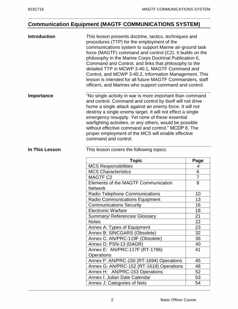
In This Lesson This lesson covers the following topics: Topic Page
MCS Responsibilities 4
MCS Characteristics 6
MAGTF C2 7
Elements of the MAGTF Communication Network
8
Radio Telephone Communications 10
Radio Communications Equipment 13
Communications Security 16
Electronic Warfare 18
Summary/ References/ Glossary 21
Notes 22
Annex A: Types of Equipment 23
Annex B: SINCGARS (Obsolete) 32
Annex C: AN/PRC-119F (Obsolete) 36
Annex D: PSN-13 (DAGR) 40
Annex E: AN/PRC-117F (RT-1796) Operations
41
Annex F: AN/PRC-150 (RT-1694) Operations 45
Annex G: AN/PRC-152 (RT-1619) Operations 48
Annex H: AN/PRC-153 Operations 52
Annex I: Julian Date Calendar 53
Annex J: Categories of Nets 54
B191716 MAGTF COMMUNICATIONS SYSTEM
3 Basic Officer Course
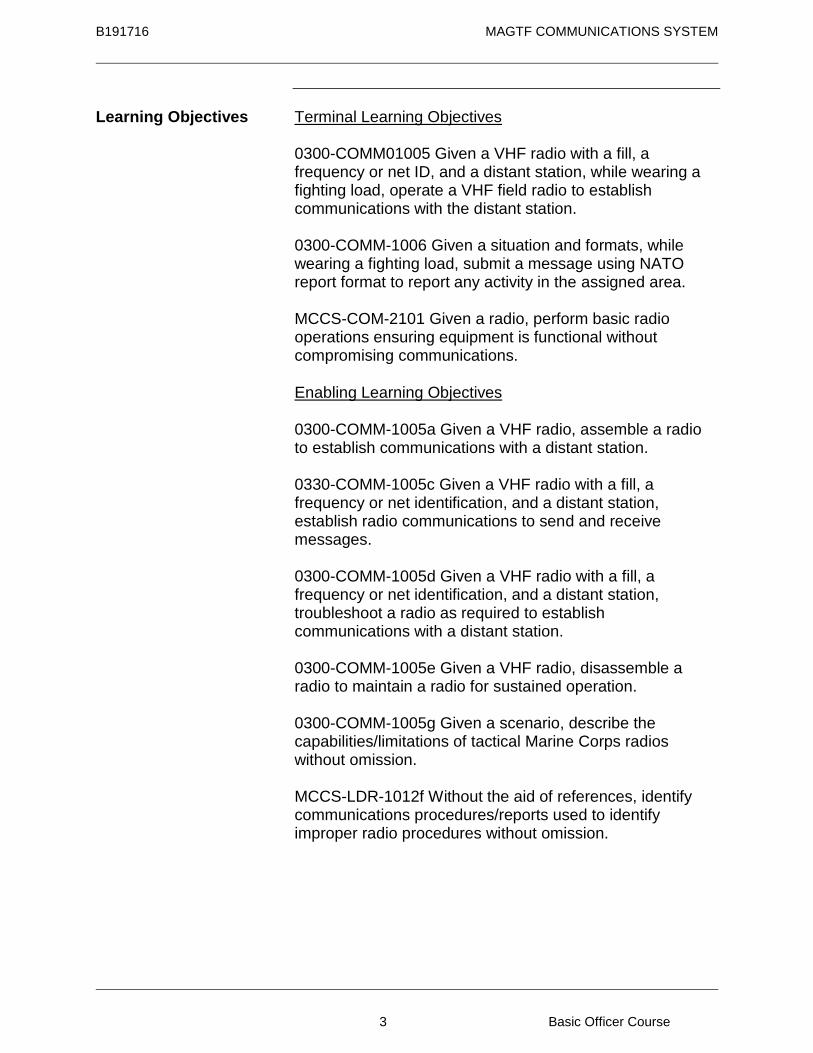
Learning Objectives Terminal Learning Objectives 0300-COMM01005 Given a VHF radio with a fill, a frequency or net ID, and a distant station, while wearing a fighting load, operate a VHF field radio to establish communications with the distant station. 0300-COMM-1006 Given a situation and formats, while wearing a fighting load, submit a message using NATO report format to report any activity in the assigned area. MCCS-COM-2101 Given a radio, perform basic radio operations ensuring equipment is functional without compromising communications.
Enabling Learning Objectives
0300-COMM-1005a Given a VHF radio, assemble a radio to establish communications with a distant station. 0330-COMM-1005c Given a VHF radio with a fill, a frequency or net identification, and a distant station, establish radio communications to send and receive messages. 0300-COMM-1005d Given a VHF radio with a fill, a frequency or net identification, and a distant station, troubleshoot a radio as required to establish communications with a distant station. 0300-COMM-1005e Given a VHF radio, disassemble a radio to maintain a radio for sustained operation. 0300-COMM-1005g Given a scenario, describe the capabilities/limitations of tactical Marine Corps radios without omission. MCCS-LDR-1012f Without the aid of references, identify communications procedures/reports used to identify improper radio procedures without omission.
B191716 MAGTF COMMUNICATIONS SYSTEM
4 Basic Officer Course
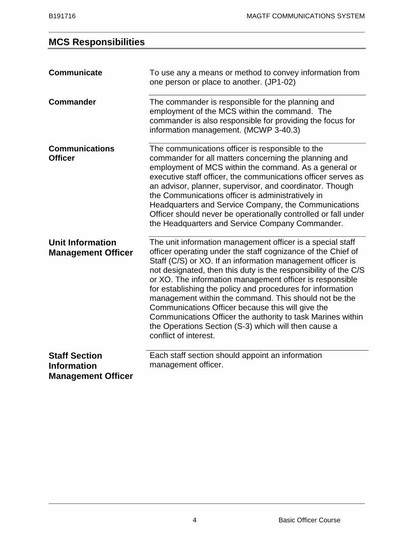
MCS Responsibilities
Communicate To use any a means or method to convey information from
one person or place to another. (JP1-02)
Commander The commander is responsible for the planning and employment of the MCS within the command. The commander is also responsible for providing the focus for information management. (MCWP 3-40.3)
Communications Officer
The communications officer is responsible to the commander for all matters concerning the planning and employment of MCS within the command. As a general or executive staff officer, the communications officer serves as an advisor, planner, supervisor, and coordinator. Though the Communications officer is administratively in Headquarters and Service Company, the Communications Officer should never be operationally controlled or fall under the Headquarters and Service Company Commander.
Unit Information Management Officer
The unit information management officer is a special staff officer operating under the staff cognizance of the Chief of Staff (C/S) or XO. If an information management officer is not designated, then this duty is the responsibility of the C/S or XO. The information management officer is responsible for establishing the policy and procedures for information management within the command. This should not be the Communications Officer because this will give the Communications Officer the authority to task Marines within the Operations Section (S-3) which will then cause a conflict of interest.
Staff Section Information Management Officer
Each staff section should appoint an information management officer.
B191716 MAGTF COMMUNICATIONS SYSTEM
5 Basic Officer Course
MCS Responsibilities (Continued)
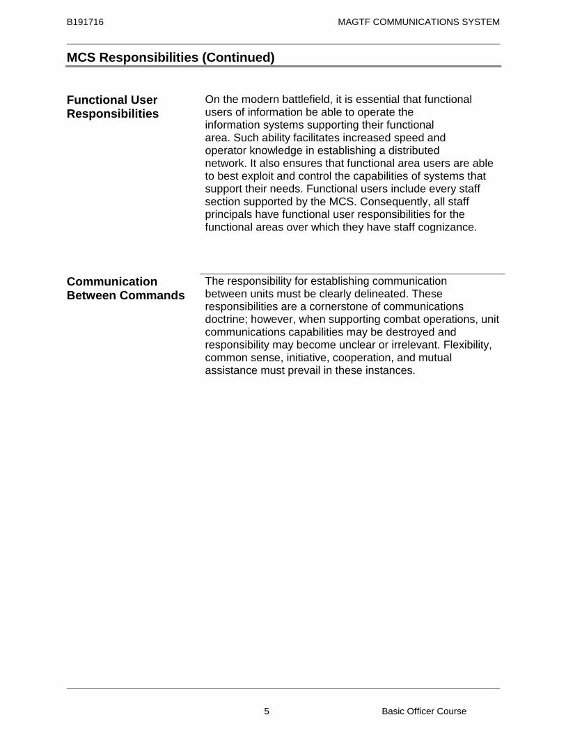
Functional User Responsibilities
On the modern battlefield, it is essential that functional users of information be able to operate the information systems supporting their functional area. Such ability facilitates increased speed and operator knowledge in establishing a distributed network. It also ensures that functional area users are able to best exploit and control the capabilities of systems that support their needs. Functional users include every staff section supported by the MCS. Consequently, all staff principals have functional user responsibilities for the functional areas over which they have staff cognizance.
Communication Between Commands
The responsibility for establishing communication between units must be clearly delineated. These responsibilities are a cornerstone of communications doctrine; however, when supporting combat operations, unit communications capabilities may be destroyed and responsibility may become unclear or irrelevant. Flexibility, common sense, initiative, cooperation, and mutual assistance must prevail in these instances.
B191716 MAGTF COMMUNICATIONS SYSTEM
6 Basic Officer Course
MCS Characteristics
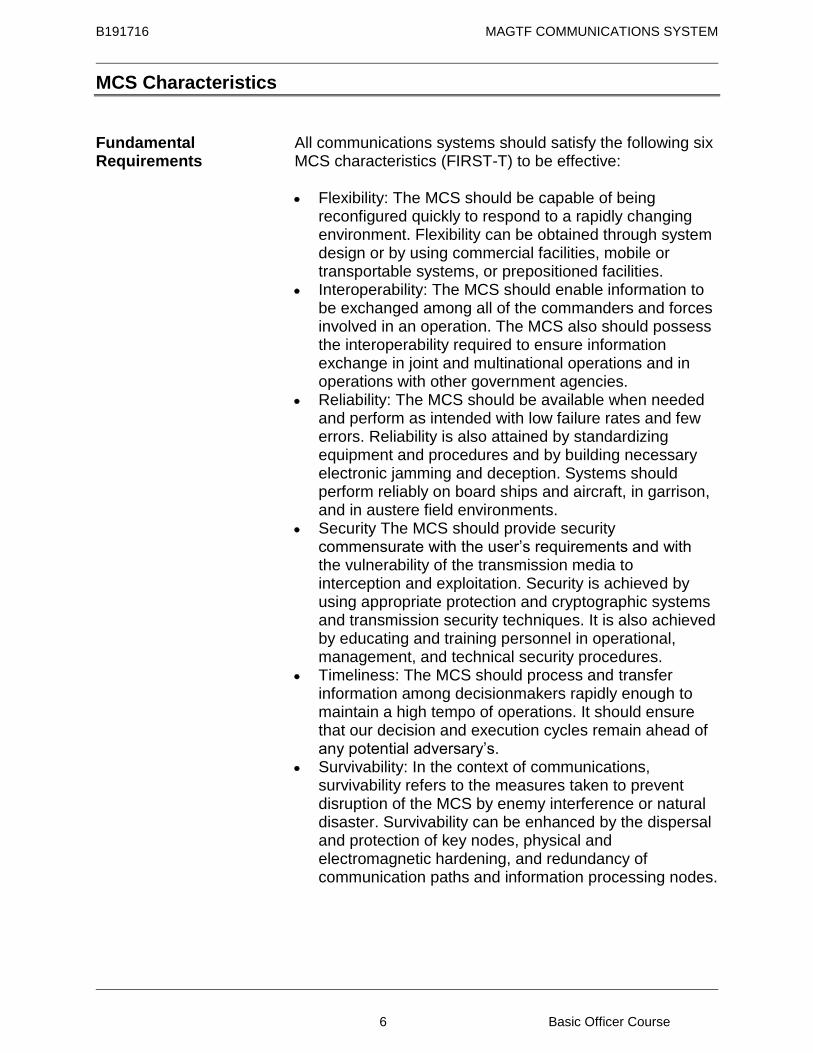
Fundamental Requirements
All communications systems should satisfy the following six MCS characteristics (FIRST-T) to be effective:
Flexibility: The MCS should be capable of being reconfigured quickly to respond to a rapidly changing environment. Flexibility can be obtained through system design or by using commercial facilities, mobile or transportable systems, or prepositioned facilities.
Interoperability: The MCS should enable information to be exchanged among all of the commanders and forces involved in an operation. The MCS also should possess the interoperability required to ensure information exchange in joint and multinational operations and in operations with other government agencies.
Reliability: The MCS should be available when needed and perform as intended with low failure rates and few errors. Reliability is also attained by standardizing equipment and procedures and by building necessary electronic jamming and deception. Systems should perform reliably on board ships and aircraft, in garrison, and in austere field environments.
Security The MCS should provide security commensurate with the user’s requirements and with the vulnerability of the transmission media to interception and exploitation. Security is achieved by using appropriate protection and cryptographic systems and transmission security techniques. It is also achieved by educating and training personnel in operational, management, and technical security procedures.
Timeliness: The MCS should process and transfer information among decisionmakers rapidly enough to maintain a high tempo of operations. It should ensure that our decision and execution cycles remain ahead of any potential adversary’s.
Survivability: In the context of communications, survivability refers to the measures taken to prevent disruption of the MCS by enemy interference or natural disaster. Survivability can be enhanced by the dispersal and protection of key nodes, physical and electromagnetic hardening, and redundancy of communication paths and information processing nodes.
B191716 MAGTF COMMUNICATIONS SYSTEM
7 Basic Officer Course
MAGTF C2
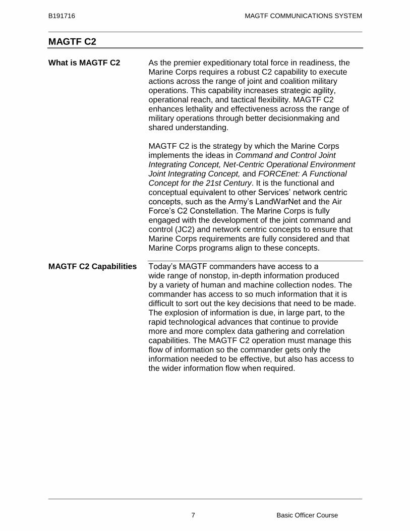
What is MAGTF C2 As the premier expeditionary total force in readiness, the Marine Corps requires a robust C2 capability to execute actions across the range of joint and coalition military operations. This capability increases strategic agility, operational reach, and tactical flexibility. MAGTF C2 enhances lethality and effectiveness across the range of military operations through better decisionmaking and shared understanding.
MAGTF C2 is the strategy by which the Marine Corps implements the ideas in Command and Control Joint Integrating Concept, Net-Centric Operational Environment Joint Integrating Concept, and FORCEnet: A Functional Concept for the 21st Century. It is the functional and conceptual equivalent to other Services’ network centric concepts, such as the Army’s LandWarNet and the Air Force’s C2 Constellation. The Marine Corps is fully engaged with the development of the joint command and control (JC2) and network centric concepts to ensure that Marine Corps requirements are fully considered and that Marine Corps programs align to these concepts.
MAGTF C2 Capabilities Today’s MAGTF commanders have access to a wide range of nonstop, in-depth information produced by a variety of human and machine collection nodes. The commander has access to so much information that it is difficult to sort out the key decisions that need to be made. The explosion of information is due, in large part, to the rapid technological advances that continue to provide more and more complex data gathering and correlation capabilities. The MAGTF C2 operation must manage this flow of information so the commander gets only the information needed to be effective, but also has access to the wider information flow when required.
B191716 MAGTF COMMUNICATIONS SYSTEM
8 Basic Officer Course
Elements of a MAGTF Communications Network
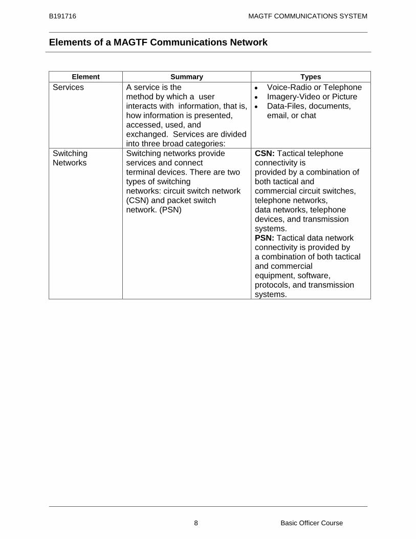
Element Summary Types
Services A service is the method by which a user interacts with information, that is, how information is presented, accessed, used, and exchanged. Services are divided into three broad categories:
Voice-Radio or Telephone Imagery-Video or Picture Data-Files, documents,
email, or chat
Switching Networks
Switching networks provide services and connect terminal devices. There are two types of switching networks: circuit switch network (CSN) and packet switch network. (PSN)
CSN: Tactical telephone connectivity is provided by a combination of both tactical and commercial circuit switches, telephone networks, data networks, telephone devices, and transmission systems. PSN: Tactical data network connectivity is provided by a combination of both tactical and commercial equipment, software, protocols, and transmission systems.
B191716 MAGTF COMMUNICATIONS SYSTEM
9 Basic Officer Course
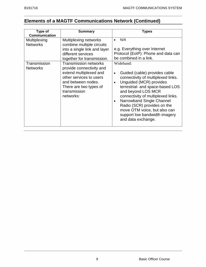
Elements of a MAGTF Communications Network (Continued)
Type of Communication
Summary Types
Multiplexing Networks
Multiplexing networks combine multiple circuits into a single link and layer different services together for transmission.
N/A
e.g. Everything over Internet Protocol (EoIP): Phone and data can be combined in a link.
Transmission Networks
Transmission networks provide connectivity and extend multiplexed and other services to users and between nodes. There are two types of transmission networks:
Wideband:
Guided (cable) provides cable connectivity of multiplexed links.
Unguided (MCR) provides terrestrial- and space-based LOS and beyond LOS MCR connectivity of multiplexed links.
Narrowband Single Channel Radio (SCR) provides on the move OTM voice, but also can support low bandwidth imagery and data exchange.
B191716 MAGTF COMMUNICATIONS SYSTEM
10 Basic Officer Course
Radio Telephone Communications
Radio Wave Fundamentals
Radio communication uses energy in the form of electromagnetic waves that propagate through space at the speed of light. Since the mechanics of wave motion are much the same for all types of waves, the nature of radio wave motion and propagation can be understood by comparing it with surface waves on water.
Almost everyone has thrown a stone into a pond and watched waves from the splash spread out over the surface of the water in ever increasing concentric circles. If the pond is large enough, the waves can be seen to grow weaker as they move away from the point of origin until they disappear.
Radio waves behave in a similar manner, except they expand in three-dimensional space. Radio waves travel along the surface of the earth (ground waves) and up into the atmosphere (sky waves).
Frequency and Wavelength
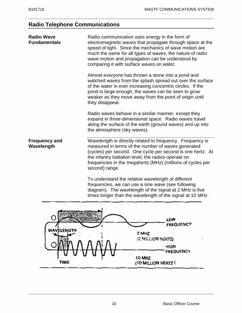
Wavelength is directly related to frequency. Frequency is measured in terms of the number of waves generated (cycles) per second. One cycle per second is one hertz. At the infantry battalion level, the radios operate on frequencies in the megahertz (MHz) (millions of cycles per second) range.
To understand the relative wavelength of different frequencies, we can use a sine wave (see following diagram). The wavelength of the signal at 2 MHz is five times longer than the wavelength of the signal at 10 MHz.
B191716 MAGTF COMMUNICATIONS SYSTEM
11 Basic Officer Course
Radio Telephone Communications (Continued)
Frequency and Wavelength (Continued)
The length of the radio wave affects the wave's propagation path. The longer wavelength (lower frequency) allows the wave to bend around and over larger obstacles, such as hills or buildings. As the wavelength shortens (increase in frequency), the waves ability to bend around obstacles decreases.
To illustrate, imagine making a 90-degree turn in a car while driving at a speed of 5 miles per hour (MPH). Now, imagine attempting the same turn at 55 MPH. The lower speed allows you to turn at a greater angle. The same holds true for lower frequencies.
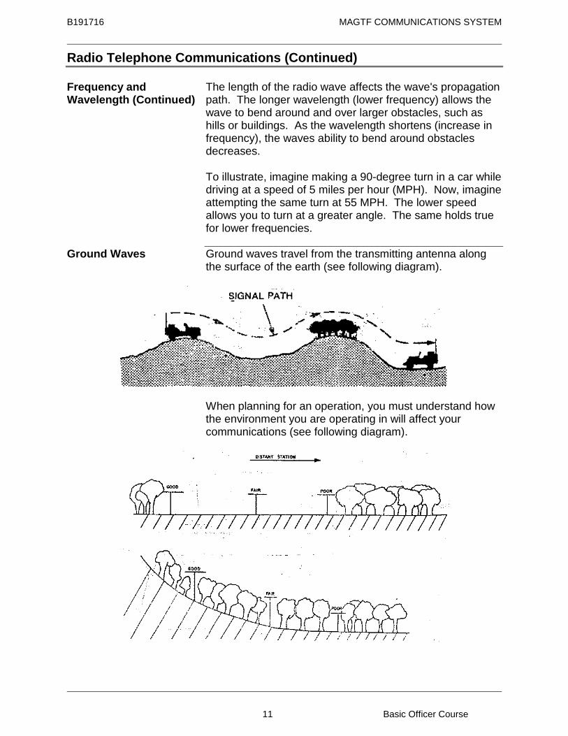
Ground Waves Ground waves travel from the transmitting antenna along the surface of the earth (see following diagram).
When planning for an operation, you must understand how the environment you are operating in will affect your communications (see following diagram).
B191716 MAGTF COMMUNICATIONS SYSTEM
12 Basic Officer Course
Radio Telephone Communications (Continued)
Ground Waves (Continued)
Several factors can affect the distance/range these waves travel
Dense vegetation, mountainous terrain, or dry desert soil can negatively affect a ground wave.
Manmade features, such as buildings, power lines, or water towers, can reflect a radio wave into a new direction or absorb the signal.
Severe weather, such as sandstorms, thunderstorms, and blizzards, can affect your radio signal.
Planning considerations for ground waves are to
Position your antenna on the military crest. Position your antenna as far back as possible from
obstacles in the direction you want to communicate. Plan for and be prepared to use relay/retransmission
stations. Select a scheme of maneuver that allows you to avoid
or exploit certain obstacles.
NOTE: Remember, the enemy will be attempting to listen to your radio transmissions. If you can position your antenna so a natural or manmade obstacle is between you and the enemy, you can reduce his ability to intercept your transmissions.
Sky waves As mentioned earlier, radio waves travel up into the atmosphere (sky waves). Because lower frequencies have longer wavelengths, when they travel into the upper regions of the atmosphere, they can be reflected (or bounced) back down to the earth's surface. Also, the wave can reflect off the earth's surface. We use this property of "bouncing" the radio signal off the ionosphere and the earth's surface to increase the range of our communications. In fact, the wave can continue this cycle of bouncing back and forth between the ionosphere and the earth's surface all the way around the earth.
Remember, however, this property is restricted to frequencies from approximately 2 to 12 MHz. Frequencies above this range tend to "punch" through the ionosphere and continue out into space.
B191716 MAGTF COMMUNICATIONS SYSTEM
13 Basic Officer Course
Radio Telephone Communications (Continued)
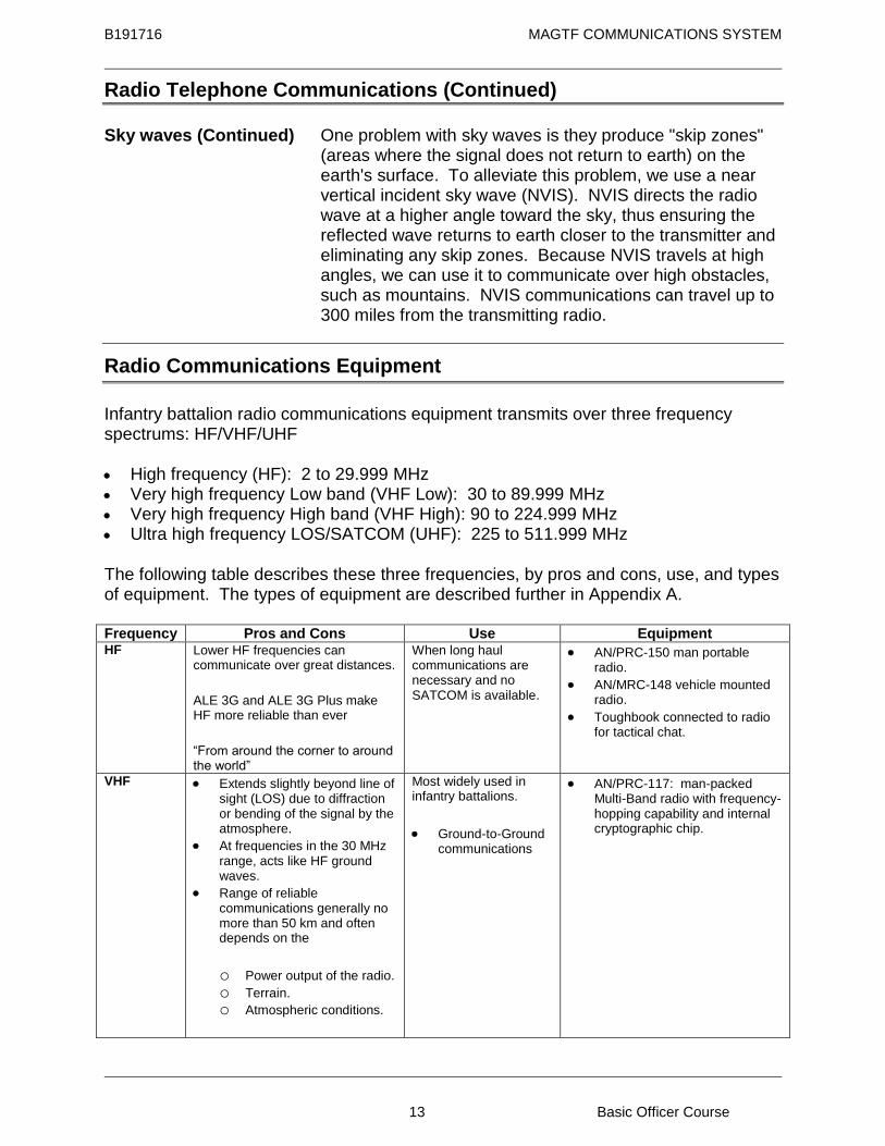
Sky waves (Continued) One problem with sky waves is they produce "skip zones" (areas where the signal does not return to earth) on the earth's surface. To alleviate this problem, we use a near vertical incident sky wave (NVIS). NVIS directs the radio wave at a higher angle toward the sky, thus ensuring the reflected wave returns to earth closer to the transmitter and eliminating any skip zones. Because NVIS travels at high angles, we can use it to communicate over high obstacles, such as mountains. NVIS communications can travel up to 300 miles from the transmitting radio.
Radio Communications Equipment
Infantry battalion radio communications equipment transmits over three frequency spectrums: HF/VHF/UHF
High frequency (HF): 2 to 29.999 MHz Very high frequency Low band (VHF Low): 30 to 89.999 MHz Very high frequency High band (VHF High): 90 to 224.999 MHz Ultra high frequency LOS/SATCOM (UHF): 225 to 511.999 MHz
The following table describes these three frequencies, by pros and cons, use, and types of equipment. The types of equipment are described further in Appendix A.
Frequency Pros and Cons Use Equipment HF
Lower HF frequencies can communicate over great distances.
ALE 3G and ALE 3G Plus make HF more reliable than ever
“From around the corner to around the world”
When long haul communications are necessary and no SATCOM is available.
AN/PRC-150 man portable radio.
AN/MRC-148 vehicle mounted radio.
Toughbook connected to radio for tactical chat.
VHF Extends slightly beyond line of sight (LOS) due to diffraction or bending of the signal by the atmosphere.
At frequencies in the 30 MHz range, acts like HF ground waves.
Range of reliable communications generally no more than 50 km and often depends on the
o Power output of the radio.
o Terrain.
o Atmospheric conditions.
Most widely used in infantry battalions.
Ground-to-Ground communications
AN/PRC-117: man-packed Multi-Band radio with frequency-hopping capability and internal cryptographic chip.
B191716 MAGTF COMMUNICATIONS SYSTEM
14 Basic Officer Course
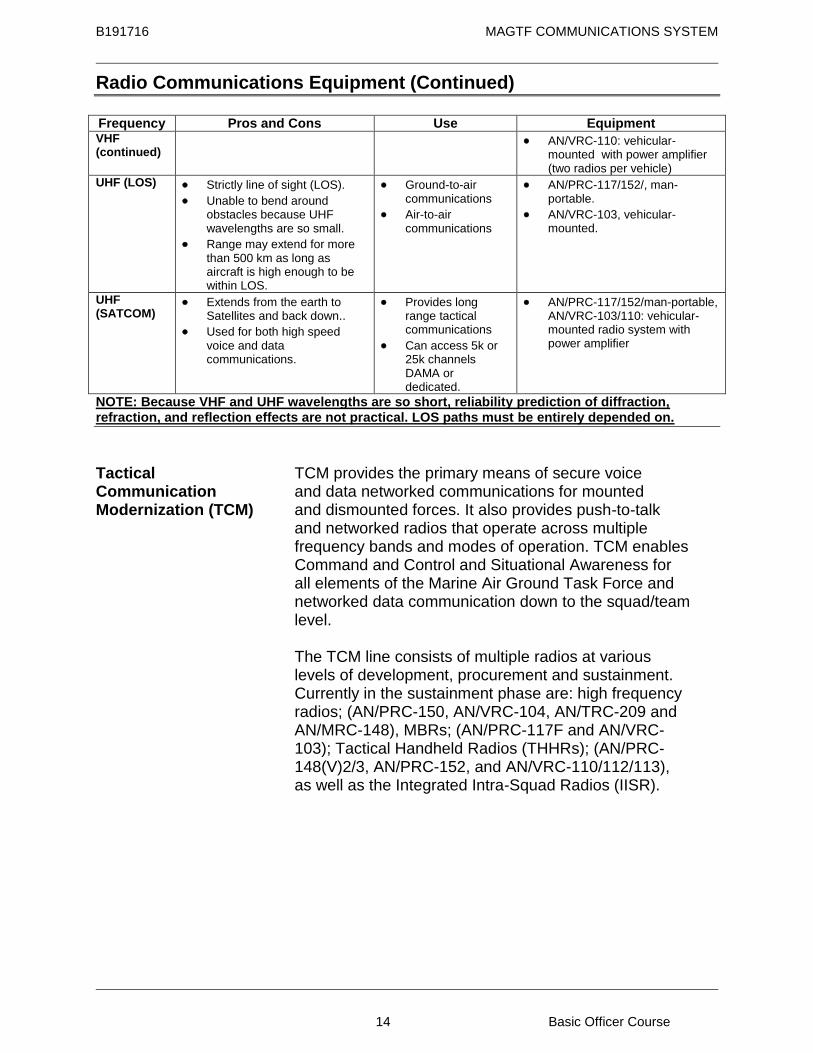
Radio Communications Equipment (Continued)
Frequency Pros and Cons Use Equipment VHF (continued)
AN/VRC-110: vehicular-mounted with power amplifier (two radios per vehicle)
UHF (LOS) Strictly line of sight (LOS).
Unable to bend around obstacles because UHF wavelengths are so small.
Range may extend for more than 500 km as long as aircraft is high enough to be within LOS.
Ground-to-air communications
Air-to-air communications
AN/PRC-117/152/, man-portable.
AN/VRC-103, vehicular-mounted.
UHF (SATCOM)
Extends from the earth to Satellites and back down..
Used for both high speed voice and data communications.
Provides long range tactical communications
Can access 5k or 25k channels DAMA or dedicated.
AN/PRC-117/152/man-portable, AN/VRC-103/110: vehicular-mounted radio system with power amplifier
NOTE: Because VHF and UHF wavelengths are so short, reliability prediction of diffraction, refraction, and reflection effects are not practical. LOS paths must be entirely depended on.
Tactical Communication Modernization (TCM)
TCM provides the primary means of secure voice and data networked communications for mounted and dismounted forces. It also provides push-to-talk and networked radios that operate across multiple frequency bands and modes of operation. TCM enables Command and Control and Situational Awareness for all elements of the Marine Air Ground Task Force and networked data communication down to the squad/team level. The TCM line consists of multiple radios at various levels of development, procurement and sustainment. Currently in the sustainment phase are: high frequency radios; (AN/PRC-150, AN/VRC-104, AN/TRC-209 and AN/MRC-148), MBRs; (AN/PRC-117F and AN/VRC- 103); Tactical Handheld Radios (THHRs); (AN/PRC- 148(V)2/3, AN/PRC-152, and AN/VRC-110/112/113), as well as the Integrated Intra-Squad Radios (IISR).
B191716 MAGTF COMMUNICATIONS SYSTEM
15 Basic Officer Course
Radio Communications Equipment (Continued)
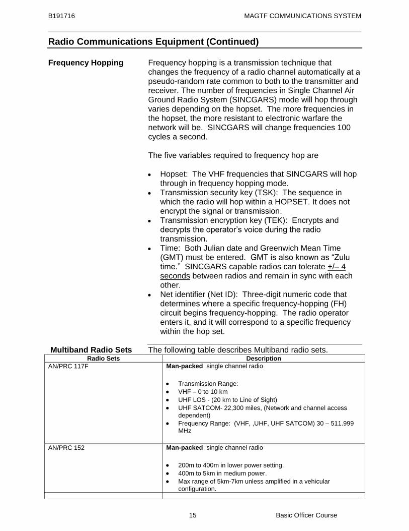
Frequency Hopping Frequency hopping is a transmission technique that changes the frequency of a radio channel automatically at a pseudo-random rate common to both to the transmitter and receiver. The number of frequencies in Single Channel Air Ground Radio System (SINCGARS) mode will hop through varies depending on the hopset. The more frequencies in the hopset, the more resistant to electronic warfare the network will be. SINCGARS will change frequencies 100 cycles a second.
The five variables required to frequency hop are
Hopset: The VHF frequencies that SINCGARS will hop through in frequency hopping mode.
Transmission security key (TSK): The sequence in which the radio will hop within a HOPSET. It does not encrypt the signal or transmission.
Transmission encryption key (TEK): Encrypts and decrypts the operator’s voice during the radio transmission.
Time: Both Julian date and Greenwich Mean Time (GMT) must be entered. GMT is also known as “Zulu time.” SINCGARS capable radios can tolerate +/– 4 seconds between radios and remain in sync with each other.
Net identifier (Net ID): Three-digit numeric code that determines where a specific frequency-hopping (FH) circuit begins frequency-hopping. The radio operator enters it, and it will correspond to a specific frequency within the hop set.
Multiband Radio Sets The following table describes Multiband radio sets. Radio Sets Description
AN/PRC 117F Man-packed single channel radio
Transmission Range:
VHF – 0 to 10 km
UHF LOS - (20 km to Line of Sight)
UHF SATCOM- 22,300 miles, (Network and channel access dependent)
Frequency Range: (VHF, ,UHF, UHF SATCOM) 30 – 511.999 MHz
AN/PRC 152 Man-packed single channel radio
200m to 400m in lower power setting.
400m to 5km in medium power.
Max range of 5km-7km unless amplified in a vehicular configuration.
B191716 MAGTF COMMUNICATIONS SYSTEM
16 Basic Officer Course
Radio Communication Equipment (Continued)
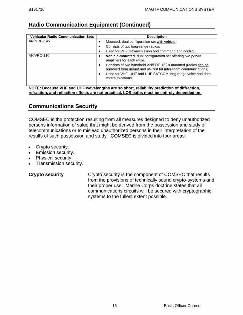
Vehicular Radio Communication Sets Description
AN/MRC-145 Mounted, dual configuration set with vehicle.
Consists of two long-range radios.
Used for VHF retransmission and command and control.
AN/VRC-110 Vehicle-mounted, dual configuration set offering two power
amplifiers for each radio.
Consists of two handheld AN/PRC 152’s mounted (radios can be removed from mount and utilized for inter-team communications).
Used for VHF, UHF and UHF SATCOM long range voice and data communications.
NOTE: Because VHF and UHF wavelengths are so short, reliability prediction of diffraction, refraction, and reflection effects are not practical. LOS paths must be entirely depended on.
Communications Security
COMSEC is the protection resulting from all measures designed to deny unauthorized persons information of value that might be derived from the possession and study of telecommunications or to mislead unauthorized persons in their interpretation of the results of such possession and study. COMSEC is divided into four areas:
Crypto security. Emission security. Physical security. Transmission security.
Crypto security Crypto security is the component of COMSEC that results from the provisions of technically sound crypto-systems and their proper use. Marine Corps doctrine states that all communications circuits will be secured with cryptographic systems to the fullest extent possible.
B191716 MAGTF COMMUNICATIONS SYSTEM
17 Basic Officer Course
Communications Security (Continued)
Emission Security Emission security is the component of COMSEC which results from all measures taken to deny unauthorized persons information of value that might be derived from intercept and analysis of compromising emanations from crypto-equipment and telecommunications systems. The most widely known form of emission security is emissions control (EMCON).
EMCON involves the reduction or elimination of emissions (e.g., radio signals, radar signals, etc.). Commanders will set EMCON to reduce their unit's electromagnetic signature to deny the enemy electronic warfare (EW) units the ability to gain our communications order of battle (COB) and electronic order of battle (EOB).
Refrain from inadvertently divulging plans for an upcoming attack. Many units increase their radio transmissions shortly before commencing an attack. Even if we use crypto-systems properly, and the enemy cannot decipher what we are saying, the enemy may deduce that we are about to attack simply by studying the amount of traffic we are generating. To alleviate this potential problem, commanders may direct the unit to go to EMCON to deny the enemy this information.
Physical Security Physical security is the component of COMSEC that results from all physical measures taken to safeguard classified equipment, material, and documents from access or observation by unauthorized persons.
Transmissions Security Transmissions security is the component of COMSEC that results from all measures designated to protect transmissions from interception and exploitation by means other than cryptanalysis.
Cryptography Every tactical radio net in the United States Marine Corps is encrypted. To accomplish this, certain encryption devices must be used. Cryptographic equipment will secure or encode all information passed over that radio. A radio that has the capability to encrypt and decrypt transmissions without the aid of an external device is said to have “internal COMSEC.” As well, when that radio is loaded with cryptographic material, it will have its “fill.”
B191716 MAGTF COMMUNICATIONS SYSTEM
18 Basic Officer Course
Communications Security (Continued)
Cryptography (continued)
Examples of DoD radios that have internal COMSEC are: AN/PRC 152 (TYPE I Encryption) AN/PRC-150 (TYPE I Encryption) AN/PRC 117F (TYPE I Encryption) AN/PRC 153 (TYPE II Encryption)
Reaction to Violation of Transmission Security
Essential elements of friendly information (EEFIs) are specific items of information that, if disclosed, could have a negative impact on friendly operations. Reacting to transmission of EEFI is specifically enforced when transmitting over an unencrypted or “open” net. The EEFI list includes
Position. Capabilities. Operations. Friendly electronic warfare. Personnel. COMSEC. Wrong circuit.
If a friendly unit passes an EEFI over an open net, BEADWINDOW is a procedural word that brings to the immediate attention of circuit operators the fact that an EEFI disclosure has occurred.
Electronic Warfare
Electronic warfare (EW) is a broad term covering any military action involving the use of electromagnetic or directed energy either to attack an enemy's combat capability or to protect friendly combat capabilities against undesirable effects of friendly or enemy use of the electromagnetic spectrum. Electronic warfare entails the surveillance of the electromagnetic spectrum for immediate threat recognition in support of electronic warfare operations and other tactical actions such as threat avoidance, targeting, and homing.
Preventive Measures As stated previously, electronic protection are those measures taken which allow for the continued use of the electromagnetic spectrum, despite enemy efforts to reduce or eliminate our use of that medium. Electronic protection can be either preventive or remedial in nature.
B191716 MAGTF COMMUNICATIONS SYSTEM
19 Basic Officer Course
Electronic Warfare (Continued)
Preventive Measures (Continued)
Preventive measures are simply techniques for avoiding exploitation by the enemy. Avoiding enemy jamming is primarily a matter of avoiding detection; avoiding enemy deception efforts requires operators to ensure those signals that might be intercepted by the enemy contain as little usable information as possible. Some prevention techniques
Reduce electronic traffic to a minimum (communication by exception) through clearly communicated, good tactical plans that include mission orders, commander's intent, and a focus of effort.
Well-developed and exercised standard operating procedures (SOPs) to include brevity codes, communication by exception, low power electronic-equipment usage, directional antennas, etc.
Thorough training in the installation and operation of equipment, including proper antenna sitting (to allow for terrain masking of electronic signatures), directional antennas, etc.
The use of alternate means of communication when possible (e.g., messengers, wire, visual, etc.).
The use of cryptographic COMSEC equipment to secure your transmissions.
Use approved operation codes, i.e. not locally developed ones that are very simple to break.
If possible, select a scheme of maneuver that will minimize friendly electronic emissions. For example, have a simple scheme of maneuver that can be executed with few or no emissions, by imposing radio silence, or by selecting avenues of approach that will interpose terrain between friendly transmitters and enemy intercept stations.
Reaction to Suspected Enemy Electronic Warfare
When the station begins to suffer interference, the operator’s immediate action is to attempt to determine the cause of the problem. Since the symptoms of jamming are the same as many other types of electronic interference, the operator should not immediately assume he is the target of hostile EW activity.
B191716 MAGTF COMMUNICATIONS SYSTEM
20 Basic Officer Course
Electronic Warfare (EW) (Continued)
Reaction to Suspected Enemy Electronic Warfare (continued)
The first action the operator should take is to remove the set's antenna. If the problem continues at its original volume and intensity with the antenna removed, the operator may assume that the problem is with the equipment and not EW. The critical element for helping the operator determine if interference is EW in nature or simply a problem with the set is the operator’s level of training.
Additional remedial measures:
Do not announce or indicate that you believe you are being jammed.
Keep operating but speak slowly and authenticate all stations.
Change antenna sitting and orientation. Relocate antenna so that a building or hill is between the antenna and the source of the jamming, if known. Switch to a directional antenna.
Increase transmitter power (equipment dependent). Send high precedence traffic by another net, if possible,
but continue operating on the jammed net.
Log the jamming and report immediately to your supervisor. Send JSIR (Joint Spectrum Interference Resolution) report.
JSIR Three step resolution process:
(1) Identification, verification, characterization, and reporting.
(2) Geo-location, analysis, developing courses of action, and recommendations (corrective actions).
(3) Implementation and notification to user(s) and final closure reporting.
• The JSIR program resolves EMI at the lowest possible level using organic and/or other assets available to the command.
B191716 MAGTF COMMUNICATIONS SYSTEM
21 Basic Officer Course
Reaction to Imitative Deception (GINGERBREAD)
If the enemy is suspected of using imitative electromagnetic deception (i.e. the enemy is posing as a friendly unit) on the net, GINGERBREAD is a procedural word used to alert other stations on a radio net. An example of how this would sound is
"All stations this net (or use the net call sign), GINGERBREAD (insert the suspected enemy's call sign), over."
The other stations on the net may or may not respond to your transmission. After you have alerted everyone on the net, send a JSIR report via another secure net, if possible.
Summary
Every commander is responsible for communications within his or her unit. To be successful, a working knowledge of Marine Corps communications doctrine and equipment is vital. If you can’t communicate, you can’t command!
References
Reference Number or Author
Reference Title
FM 24-18 Tactical Single-Channel Radio Communications Techniques
TM 11-5820-890-10-6 SINCGARS ICOM Ground Radio Pocket Guide MCRP 3-11.1A Commander’s Tactical Handbook MCRP 3-40.3A Tactical Communications MCRP 3-40.3B Radio Operator’s Handbook MCWP 3-11.1 Marine Rifle Company/Platoon MCWP 3-40.3 MAGTF Communications System
Glossary of Terms and Acronyms
Term or Acronym Definition or Identification
ALE Automatic link establishment
COB Communications order of battle
COMSEC Communications security
DoD Department of Defense
EEFI Essential elements of friendly information
EMCOM Emissions Control
EOB Electronic Order of Battle
EW Electronic warfare
FH Frequency hopping
GMT Greenwich mean time
B191716 MAGTF COMMUNICATIONS SYSTEM
22 Basic Officer Course
GPS Global positioning system
HF High frequency
LOS Line of sight
MHz Megahertz
MIJI Meaconing, intrusion, jamming, and interference
NVIS Near vertical incident skywave
SINCGARS Single channel Ground Air Radio Systems
UHF Ultra high frequency
VHF Very high frequency
Notes
B191716 MAGTF COMMUNICATIONS SYSTEM
23 Basic Officer Course
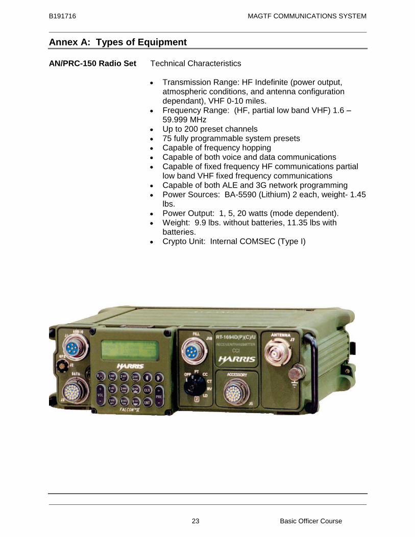
Annex A: Types of Equipment
AN/PRC-150 Radio Set Technical Characteristics
Transmission Range: HF Indefinite (power output, atmospheric conditions, and antenna configuration dependant), VHF 0-10 miles.
Frequency Range: (HF, partial low band VHF) 1.6 – 59.999 MHz
Up to 200 preset channels 75 fully programmable system presets Capable of frequency hopping Capable of both voice and data communications Capable of fixed frequency HF communications partial
low band VHF fixed frequency communications Capable of both ALE and 3G network programming Power Sources: BA-5590 (Lithium) 2 each, weight- 1.45
lbs. Power Output: 1, 5, 20 watts (mode dependent). Weight: 9.9 lbs. without batteries, 11.35 lbs with
batteries. Crypto Unit: Internal COMSEC (Type I)
B191716 MAGTF COMMUNICATIONS SYSTEM
24 Basic Officer Course
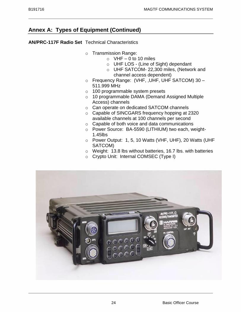
Annex A: Types of Equipment (Continued)
AN/PRC-117F Radio Set Technical Characteristics
o Transmission Range: o VHF – 0 to 10 miles o UHF LOS - (Line of Sight) dependant o UHF SATCOM- 22,300 miles, (Network and
channel access dependent) o Frequency Range: (VHF, ,UHF, UHF SATCOM) 30 –
511.999 MHz o 100 programmable system presets o 10 programmable DAMA (Demand Assigned Multiple
Access) channels o Can operate on dedicated SATCOM channels o Capable of SINCGARS frequency hopping at 2320
available channels at 100 channels per second o Capable of both voice and data communications o Power Source: BA-5590 (LITHIUM) two each, weight-
1.45lbs o Power Output: 1, 5, 10 Watts (VHF, UHF), 20 Watts (UHF
SATCOM) o Weight: 13.8 lbs without batteries, 16.7 lbs. with batteries o Crypto Unit: Internal COMSEC (Type I)
B191716 MAGTF COMMUNICATIONS SYSTEM
25 Basic Officer Course
Annex A: Types of Equipment (Continued)
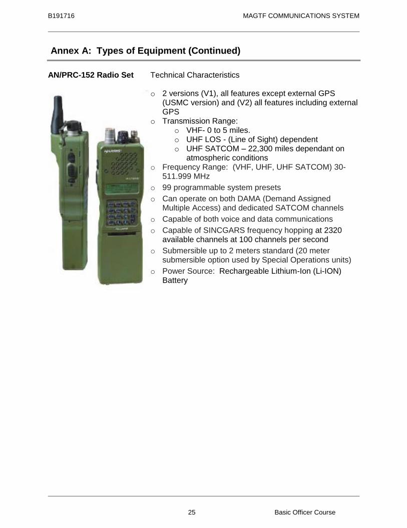
AN/PRC-152 Radio Set Technical Characteristics
o 2 versions (V1), all features except external GPS (USMC version) and (V2) all features including external GPS
o Transmission Range: o VHF- 0 to 5 miles. o UHF LOS - (Line of Sight) dependent o UHF SATCOM – 22,300 miles dependant on
atmospheric conditions o Frequency Range: (VHF, UHF, UHF SATCOM) 30-
511.999 MHz
o 99 programmable system presets
o Can operate on both DAMA (Demand Assigned Multiple Access) and dedicated SATCOM channels
o Capable of both voice and data communications
o Capable of SINCGARS frequency hopping at 2320 available channels at 100 channels per second
o Submersible up to 2 meters standard (20 meter submersible option used by Special Operations units)
o Power Source: Rechargeable Lithium-Ion (Li-ION) Battery
B191716 MAGTF COMMUNICATIONS SYSTEM
26 Basic Officer Course
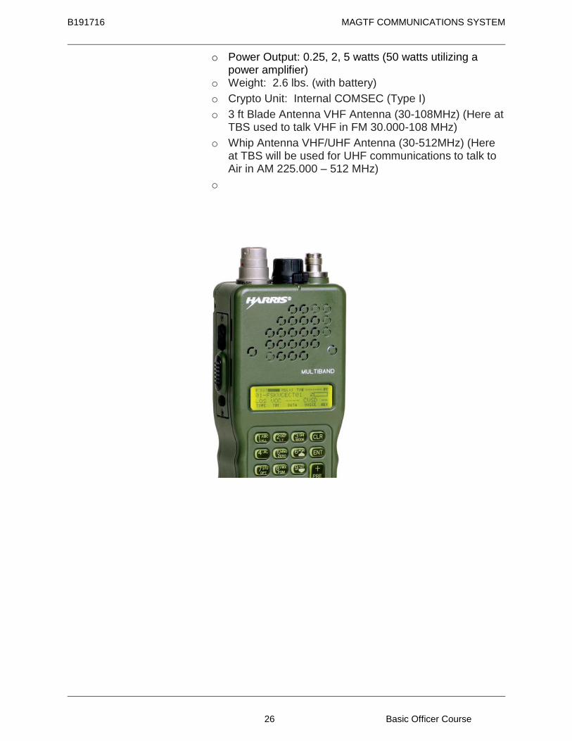
o Power Output: 0.25, 2, 5 watts (50 watts utilizing a power amplifier)
o Weight: 2.6 lbs. (with battery)
o Crypto Unit: Internal COMSEC (Type I)
o 3 ft Blade Antenna VHF Antenna (30-108MHz) (Here at TBS used to talk VHF in FM 30.000-108 MHz)
o Whip Antenna VHF/UHF Antenna (30-512MHz) (Here at TBS will be used for UHF communications to talk to Air in AM 225.000 – 512 MHz)
o
B191716 MAGTF COMMUNICATIONS SYSTEM
27 Basic Officer Course
Annex A: Types of Equipment (Continued)
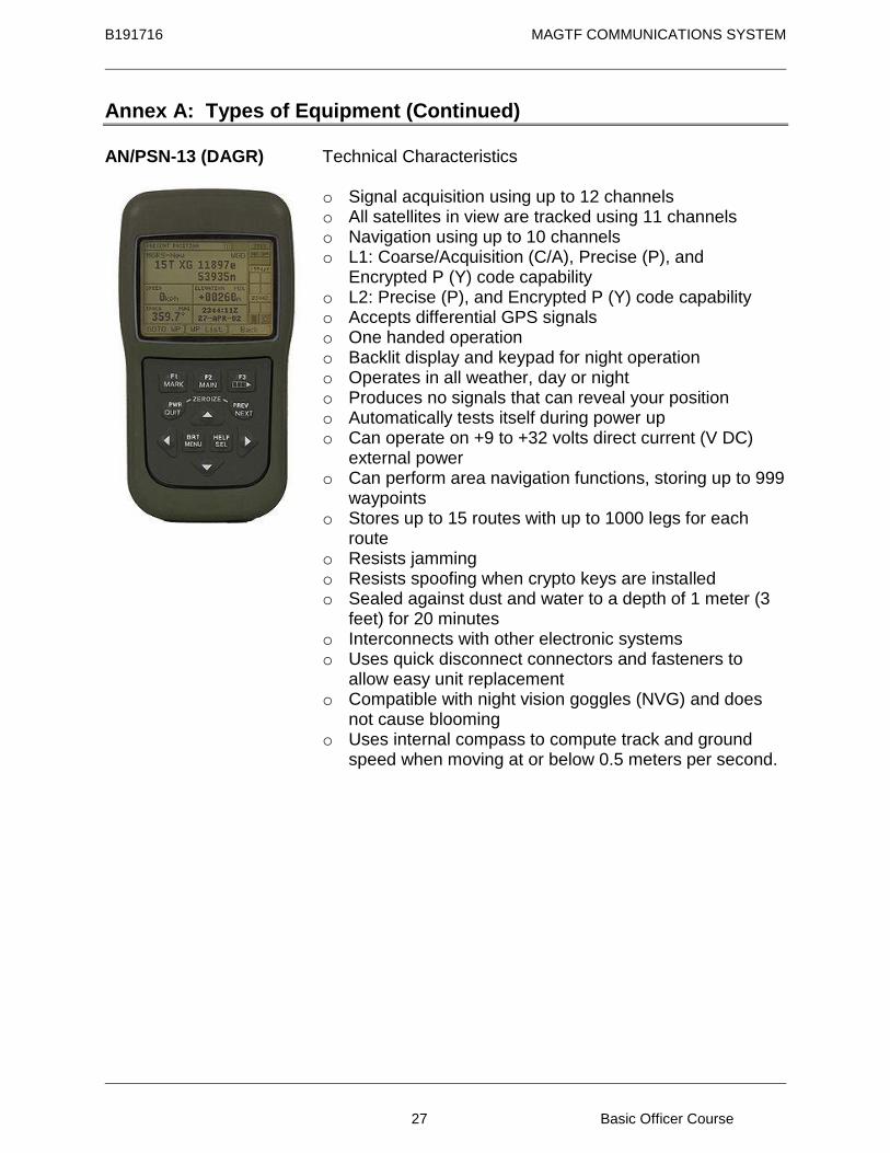
AN/PSN-13 (DAGR) Technical Characteristics
o Signal acquisition using up to 12 channels o All satellites in view are tracked using 11 channels o Navigation using up to 10 channels o L1: Coarse/Acquisition (C/A), Precise (P), and
Encrypted P (Y) code capability o L2: Precise (P), and Encrypted P (Y) code capability o Accepts differential GPS signals o One handed operation o Backlit display and keypad for night operation o Operates in all weather, day or night o Produces no signals that can reveal your position o Automatically tests itself during power up o Can operate on +9 to +32 volts direct current (V DC)
external power o Can perform area navigation functions, storing up to 999
waypoints o Stores up to 15 routes with up to 1000 legs for each
route o Resists jamming o Resists spoofing when crypto keys are installed o Sealed against dust and water to a depth of 1 meter (3
feet) for 20 minutes o Interconnects with other electronic systems o Uses quick disconnect connectors and fasteners to
allow easy unit replacement o Compatible with night vision goggles (NVG) and does
not cause blooming o Uses internal compass to compute track and ground
speed when moving at or below 0.5 meters per second.
B191716 MAGTF COMMUNICATIONS SYSTEM
28 Basic Officer Course
Annex A: Types of Equipment (Continued)
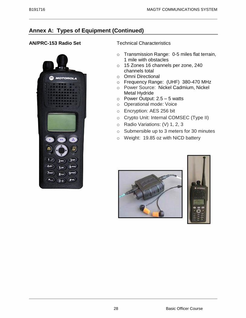
AN/PRC-153 Radio Set Technical Characteristics
o Transmission Range: 0-5 miles flat terrain, 1 mile with obstacles
o 15 Zones 16 channels per zone, 240 channels total
o Omni Directional o Frequency Range: (UHF) 380-470 MHz o Power Source: Nickel Cadmium, Nickel
Metal Hydride o Power Output: 2.5 – 5 watts o Operational mode: Voice
o Encryption: AES 256 bit
o Crypto Unit: Internal COMSEC (Type II)
o Radio Variations: (V) 1, 2, 3
o Submersible up to 3 meters for 30 minutes
o Weight: 19.85 oz with NiCD battery
B191716 MAGTF COMMUNICATIONS SYSTEM
29 Basic Officer Course
Annex A: Types of Equipment (Continued)
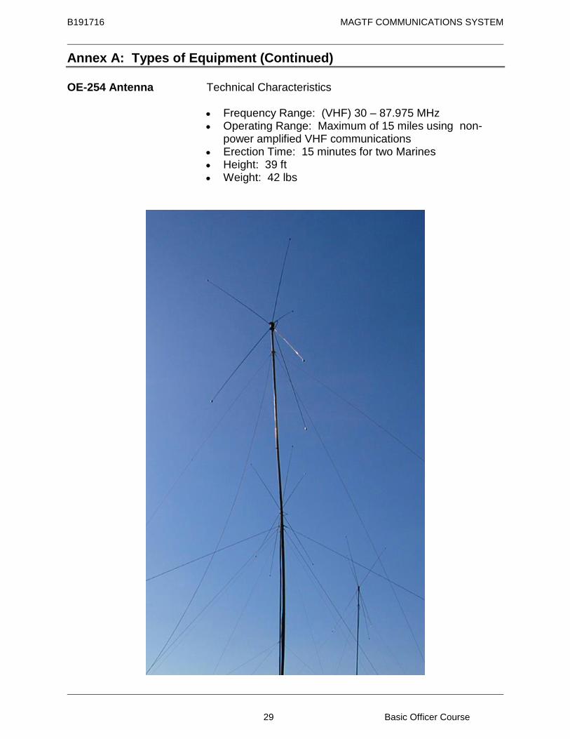
OE-254 Antenna Technical Characteristics
Frequency Range: (VHF) 30 – 87.975 MHz Operating Range: Maximum of 15 miles using non-
power amplified VHF communications Erection Time: 15 minutes for two Marines Height: 39 ft Weight: 42 lbs
B191716 MAGTF COMMUNICATIONS SYSTEM
30 Basic Officer Course
Annex A: Types of Equipment (Continued)
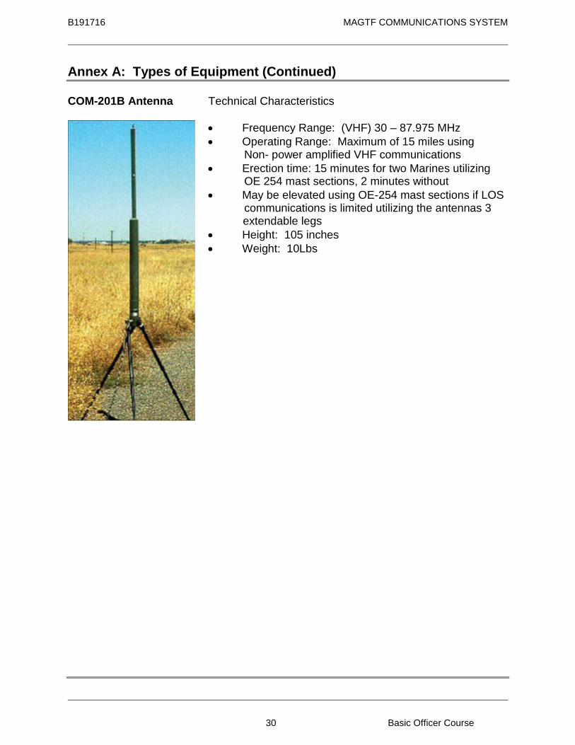
COM-201B Antenna Technical Characteristics
Frequency Range: (VHF) 30 – 87.975 MHz
Operating Range: Maximum of 15 miles using Non- power amplified VHF communications
Erection time: 15 minutes for two Marines utilizing OE 254 mast sections, 2 minutes without
May be elevated using OE-254 mast sections if LOS communications is limited utilizing the antennas 3
extendable legs
Height: 105 inches
Weight: 10Lbs
B191716 MAGTF COMMUNICATIONS SYSTEM
31 Basic Officer Course
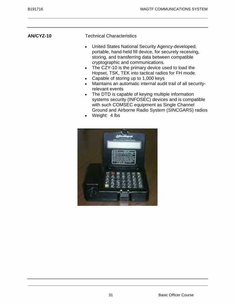
AN/CYZ-10 Technical Characteristics
United States National Security Agency-developed, portable, hand-held fill device, for securely receiving, storing, and transferring data between compatible cryptographic and communications.
The CZY-10 is the primary device used to load the Hopset, TSK, TEK into tactical radios for FH mode.
Capable of storing up to 1,000 keys Maintains an automatic internal audit trail of all security-
relevant events The DTD is capable of keying multiple information
systems security (INFOSEC) devices and is compatible with such COMSEC equipment as Single Channel Ground and Airborne Radio System (SINCGARS) radios
Weight: 4 lbs
B191716 MAGTF COMMUNICATIONS SYSTEM
32 Basic Officer Course
Annex B: SINCGARS (RT-1523) Operations
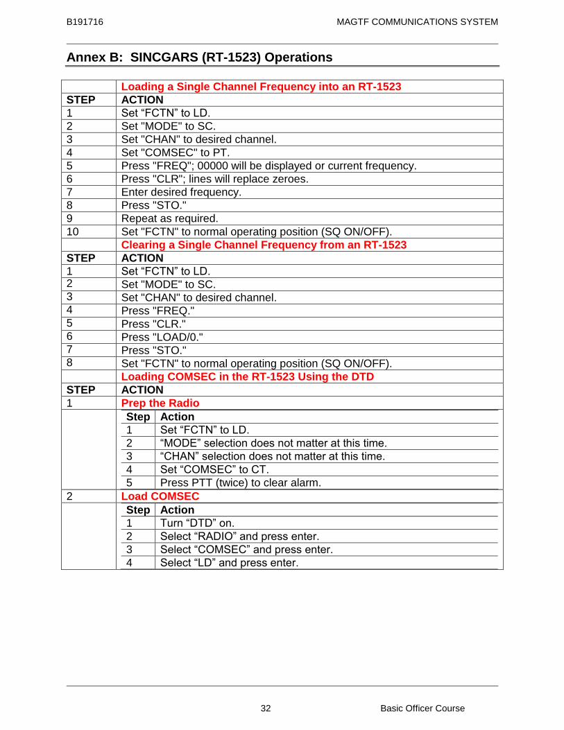
Loading a Single Channel Frequency into an RT-1523
STEP ACTION
1 Set “FCTN” to LD.
2 Set "MODE" to SC.
3 Set "CHAN" to desired channel.
4 Set "COMSEC" to PT.
5 Press "FREQ"; 00000 will be displayed or current frequency.
6 Press "CLR"; lines will replace zeroes.
7 Enter desired frequency.
8 Press "STO."
9 Repeat as required.
10 Set "FCTN" to normal operating position (SQ ON/OFF).
Clearing a Single Channel Frequency from an RT-1523
STEP ACTION
1 Set “FCTN” to LD. 2 Set "MODE" to SC. 3 Set "CHAN" to desired channel. 4 Press "FREQ." 5 Press "CLR." 6 Press "LOAD/0." 7 Press "STO." 8 Set "FCTN" to normal operating position (SQ ON/OFF).
Loading COMSEC in the RT-1523 Using the DTD
STEP ACTION
1 Prep the Radio
Step Action
1 Set “FCTN” to LD.
2 “MODE” selection does not matter at this time.
3 “CHAN” selection does not matter at this time.
4 Set “COMSEC” to CT.
5 Press PTT (twice) to clear alarm.
2 Load COMSEC
Step Action
1 Turn “DTD” on.
2 Select “RADIO” and press enter.
3 Select “COMSEC” and press enter.
4 Select “LD” and press enter.
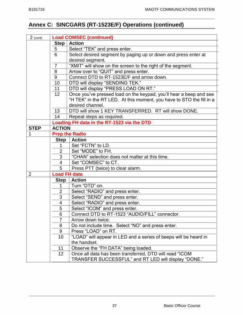
B191716 MAGTF COMMUNICATIONS SYSTEM
33 Basic Officer Course
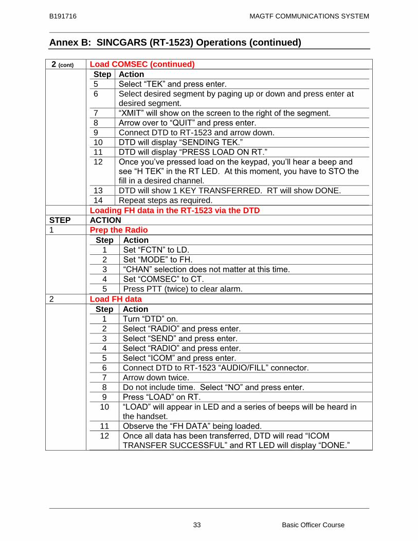
Annex B: SINCGARS (RT-1523) Operations (continued)
2 (cont) Load COMSEC (continued)
Step Action
5 Select “TEK” and press enter.
6 Select desired segment by paging up or down and press enter at desired segment.
7 “XMIT” will show on the screen to the right of the segment.
8 Arrow over to “QUIT” and press enter.
9 Connect DTD to RT-1523 and arrow down.
10 DTD will display “SENDING TEK.”
11 DTD will display “PRESS LOAD ON RT.”
12 Once you’ve pressed load on the keypad, you’ll hear a beep and see “H TEK” in the RT LED. At this moment, you have to STO the fill in a desired channel.
13 DTD will show 1 KEY TRANSFERRED. RT will show DONE.
14 Repeat steps as required.
Loading FH data in the RT-1523 via the DTD
STEP ACTION
1 Prep the Radio
Step Action
1 Set “FCTN” to LD.
2 Set “MODE” to FH.
3 “CHAN” selection does not matter at this time.
4 Set “COMSEC” to CT.
5 Press PTT (twice) to clear alarm.
2 Load FH data
Step Action
1 Turn “DTD” on.
2 Select “RADIO” and press enter.
3 Select “SEND” and press enter.
4 Select “RADIO” and press enter.
5 Select “ICOM” and press enter.
6 Connect DTD to RT-1523 “AUDIO/FILL” connector.
7 Arrow down twice.
8 Do not include time. Select “NO” and press enter.
9 Press “LOAD” on RT.
10 “LOAD” will appear in LED and a series of beeps will be heard in the handset.
11 Observe the “FH DATA” being loaded.
12 Once all data has been transferred, DTD will read “ICOM TRANSFER SUCCESSFUL” and RT LED will display “DONE.”
B191716 MAGTF COMMUNICATIONS SYSTEM
34 Basic Officer Course
Annex B: SINCGARS (RT-1523) Operations (continued)
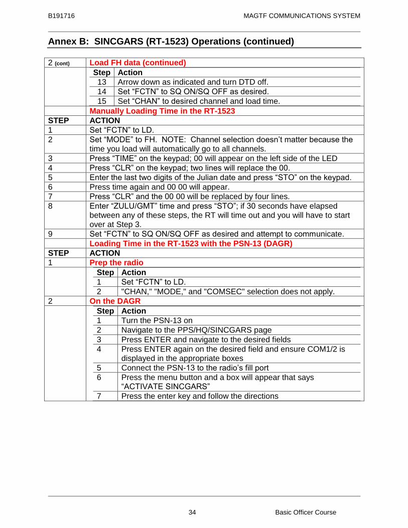
2 (cont) Load FH data (continued)
Step Action
13 Arrow down as indicated and turn DTD off.
14 Set “FCTN” to SQ ON/SQ OFF as desired.
15 Set “CHAN” to desired channel and load time.
Manually Loading Time in the RT-1523
STEP ACTION
1 Set “FCTN” to LD.
2 Set “MODE” to FH. NOTE: Channel selection doesn’t matter because the time you load will automatically go to all channels.
3 Press “TIME” on the keypad; 00 will appear on the left side of the LED
4 Press “CLR” on the keypad; two lines will replace the 00.
5 Enter the last two digits of the Julian date and press “STO” on the keypad.
6 Press time again and 00 00 will appear.
7 Press “CLR” and the 00 00 will be replaced by four lines.
8 Enter “ZULU/GMT” time and press “STO”; if 30 seconds have elapsed between any of these steps, the RT will time out and you will have to start over at Step 3.
9 Set “FCTN” to SQ ON/SQ OFF as desired and attempt to communicate.
Loading Time in the RT-1523 with the PSN-13 (DAGR)
STEP ACTION
1 Prep the radio
Step Action
1 Set “FCTN” to LD.
2 "CHAN," "MODE," and "COMSEC" selection does not apply.
2 On the DAGR
Step Action
1 Turn the PSN-13 on
2 Navigate to the PPS/HQ/SINCGARS page
3 Press ENTER and navigate to the desired fields
4 Press ENTER again on the desired field and ensure COM1/2 is displayed in the appropriate boxes
5 Connect the PSN-13 to the radio’s fill port
6 Press the menu button and a box will appear that says “ACTIVATE SINCGARS”
7 Press the enter key and follow the directions
B191716 MAGTF COMMUNICATIONS SYSTEM
35 Basic Officer Course
Annex B: SINCGARS (RT-1523) Operations (continued)
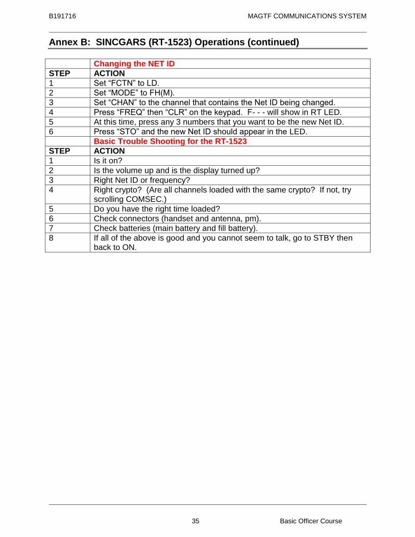
Changing the NET ID
STEP ACTION
1 Set “FCTN” to LD.
2 Set “MODE” to FH(M).
3 Set “CHAN” to the channel that contains the Net ID being changed.
4 Press “FREQ” then “CLR” on the keypad. F- - - will show in RT LED.
5 At this time, press any 3 numbers that you want to be the new Net ID.
6 Press “STO” and the new Net ID should appear in the LED.
Basic Trouble Shooting for the RT-1523
STEP ACTION
1 Is it on?
2 Is the volume up and is the display turned up?
3 Right Net ID or frequency?
4 Right crypto? (Are all channels loaded with the same crypto? If not, try scrolling COMSEC.)
5 Do you have the right time loaded?
6 Check connectors (handset and antenna, pm).
7 Check batteries (main battery and fill battery).
8 If all of the above is good and you cannot seem to talk, go to STBY then back to ON.
B191716 MAGTF COMMUNICATIONS SYSTEM
36 Basic Officer Course
Annex C: PRC-119F (RT1523E/F) OPERATIONS
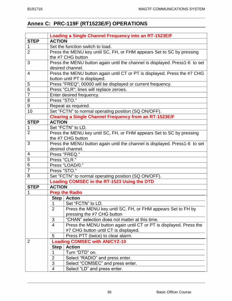
Loading a Single Channel Frequency into an RT-1523E/F
STEP ACTION
1 Set the function switch to load.
2 Press the MENU key until SC, FH, or FHM appears Set to SC by pressing the #7 CHG button
3 Press the MENU button again until the channel is displayed. Press1-6 to set desired channel.
4 Press the MENU button again until CT or PT is displayed. Press the #7 CHG button until PT is displayed.
5 Press "FREQ"; 00000 will be displayed or current frequency.
6 Press "CLR"; lines will replace zeroes.
7 Enter desired frequency.
8 Press "STO."
9 Repeat as required.
10 Set "FCTN" to normal operating position (SQ ON/OFF).
Clearing a Single Channel Frequency from an RT-1523E/F
STEP ACTION
1 Set “FCTN” to LD. 2 Press the MENU key until SC, FH, or FHM appears Set to SC by pressing
the #7 CHG button 3 Press the MENU button again until the channel is displayed. Press1-6 to set
desired channel. 4 Press "FREQ." 5 Press "CLR." 6 Press "LOAD/0." 7 Press "STO." 8 Set "FCTN" to normal operating position (SQ ON/OFF).
Loading COMSEC in the RT-1523 Using the DTD
STEP ACTION
1 Prep the Radio
Step Action
1 Set “FCTN” to LD.
2 Press the MENU key until SC, FH, or FHM appears Set to FH by pressing the #7 CHG button
3 “CHAN” selection does not matter at this time.
4 Press the MENU button again until CT or PT is displayed. Press the #7 CHG button until CT is displayed.
5 Press PTT (twice) to clear alarm.
2 Loading COMSEC with AN/CYZ-10
Step Action
1 Turn “DTD” on.
2 Select “RADIO” and press enter.
3 Select “COMSEC” and press enter.
4 Select “LD” and press enter.
B191716 MAGTF COMMUNICATIONS SYSTEM
37 Basic Officer Course
Annex C: SINCGARS (RT-1523E/F) Operations (continued)
2 (cont) Load COMSEC (continued)
Step Action
5 Select “TEK” and press enter.
6 Select desired segment by paging up or down and press enter at desired segment.
7 “XMIT” will show on the screen to the right of the segment.
8 Arrow over to “QUIT” and press enter.
9 Connect DTD to RT-1523E/F and arrow down.
10 DTD will display “SENDING TEK.”
11 DTD will display “PRESS LOAD ON RT.”
12 Once you’ve pressed load on the keypad, you’ll hear a beep and see “H TEK” in the RT LED. At this moment, you have to STO the fill in a desired channel.
13 DTD will show 1 KEY TRANSFERRED. RT will show DONE.
14 Repeat steps as required.
Loading FH data in the RT-1523 via the DTD
STEP ACTION
1 Prep the Radio
Step Action
1 Set “FCTN” to LD.
2 Set “MODE” to FH.
3 “CHAN” selection does not matter at this time.
4 Set “COMSEC” to CT.
5 Press PTT (twice) to clear alarm.
2 Load FH data
Step Action
1 Turn “DTD” on.
2 Select “RADIO” and press enter.
3 Select “SEND” and press enter.
4 Select “RADIO” and press enter.
5 Select “ICOM” and press enter.
6 Connect DTD to RT-1523 “AUDIO/FILL” connector.
7 Arrow down twice.
8 Do not include time. Select “NO” and press enter.
9 Press “LOAD” on RT.
10 “LOAD” will appear in LED and a series of beeps will be heard in the handset.
11 Observe the “FH DATA” being loaded.
12 Once all data has been transferred, DTD will read “ICOM TRANSFER SUCCESSFUL” and RT LED will display “DONE.”
B191716 MAGTF COMMUNICATIONS SYSTEM
38 Basic Officer Course
Annex C: SINCGARS (RT-1523E/F) Operations (continued)
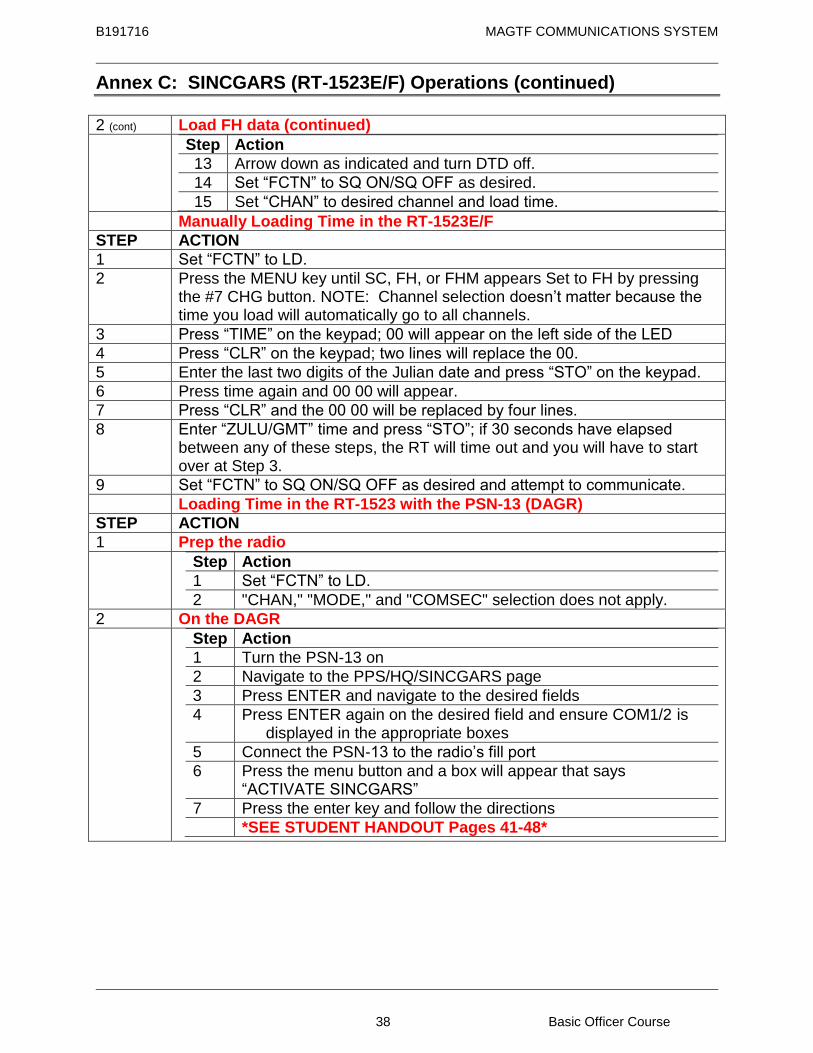
2 (cont) Load FH data (continued)
Step Action
13 Arrow down as indicated and turn DTD off.
14 Set “FCTN” to SQ ON/SQ OFF as desired.
15 Set “CHAN” to desired channel and load time.
Manually Loading Time in the RT-1523E/F
STEP ACTION
1 Set “FCTN” to LD.
2 Press the MENU key until SC, FH, or FHM appears Set to FH by pressing the #7 CHG button. NOTE: Channel selection doesn’t matter because the time you load will automatically go to all channels.
3 Press “TIME” on the keypad; 00 will appear on the left side of the LED
4 Press “CLR” on the keypad; two lines will replace the 00.
5 Enter the last two digits of the Julian date and press “STO” on the keypad.
6 Press time again and 00 00 will appear.
7 Press “CLR” and the 00 00 will be replaced by four lines.
8 Enter “ZULU/GMT” time and press “STO”; if 30 seconds have elapsed between any of these steps, the RT will time out and you will have to start over at Step 3.
9 Set “FCTN” to SQ ON/SQ OFF as desired and attempt to communicate.
Loading Time in the RT-1523 with the PSN-13 (DAGR)
STEP ACTION
1 Prep the radio
Step Action
1 Set “FCTN” to LD.
2 "CHAN," "MODE," and "COMSEC" selection does not apply.
2 On the DAGR
Step Action
1 Turn the PSN-13 on
2 Navigate to the PPS/HQ/SINCGARS page
3 Press ENTER and navigate to the desired fields
4 Press ENTER again on the desired field and ensure COM1/2 is displayed in the appropriate boxes
5 Connect the PSN-13 to the radio’s fill port
6 Press the menu button and a box will appear that says “ACTIVATE SINCGARS”
7 Press the enter key and follow the directions
*SEE STUDENT HANDOUT Pages 41-48*
B191716 MAGTF COMMUNICATIONS SYSTEM
39 Basic Officer Course
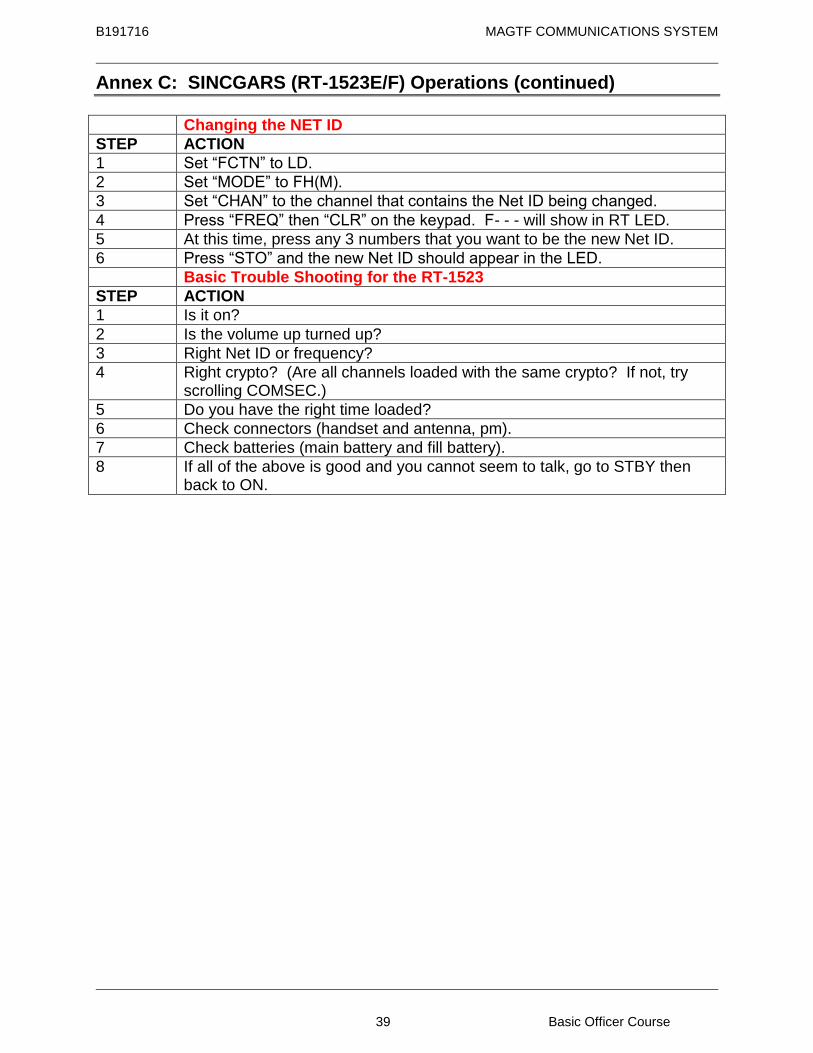
Annex C: SINCGARS (RT-1523E/F) Operations (continued)
Changing the NET ID
STEP ACTION
1 Set “FCTN” to LD.
2 Set “MODE” to FH(M).
3 Set “CHAN” to the channel that contains the Net ID being changed.
4 Press “FREQ” then “CLR” on the keypad. F- - - will show in RT LED.
5 At this time, press any 3 numbers that you want to be the new Net ID.
6 Press “STO” and the new Net ID should appear in the LED.
Basic Trouble Shooting for the RT-1523
STEP ACTION
1 Is it on?
2 Is the volume up turned up?
3 Right Net ID or frequency?
4 Right crypto? (Are all channels loaded with the same crypto? If not, try scrolling COMSEC.)
5 Do you have the right time loaded?
6 Check connectors (handset and antenna, pm).
7 Check batteries (main battery and fill battery).
8 If all of the above is good and you cannot seem to talk, go to STBY then back to ON.
B191716 MAGTF COMMUNICATIONS SYSTEM
40 Basic Officer Course
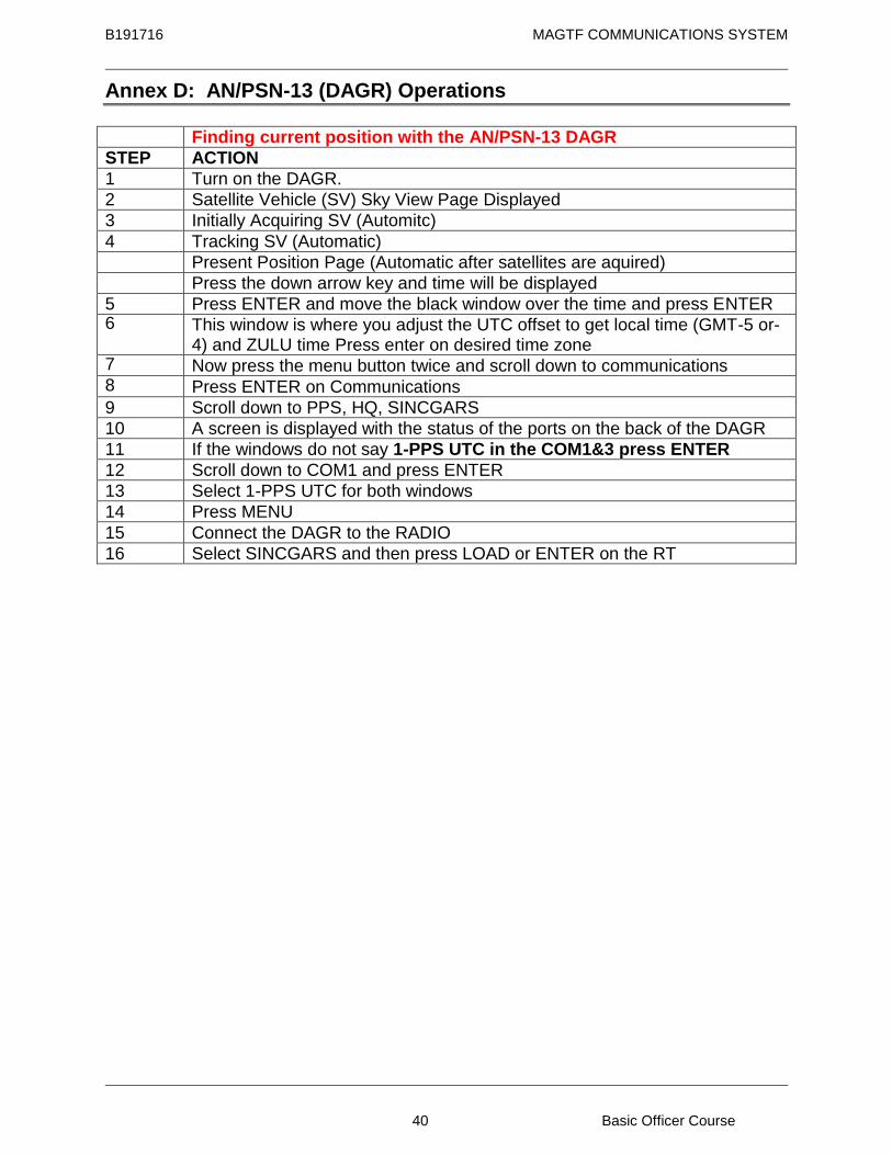
Annex D: AN/PSN-13 (DAGR) Operations
Finding current position with the AN/PSN-13 DAGR
STEP ACTION
1 Turn on the DAGR.
2 Satellite Vehicle (SV) Sky View Page Displayed
3 Initially Acquiring SV (Automitc)
4 Tracking SV (Automatic)
Present Position Page (Automatic after satellites are aquired)
Press the down arrow key and time will be displayed
5 Press ENTER and move the black window over the time and press ENTER 6 This window is where you adjust the UTC offset to get local time (GMT-5 or-
4) and ZULU time Press enter on desired time zone 7 Now press the menu button twice and scroll down to communications 8 Press ENTER on Communications
9 Scroll down to PPS, HQ, SINCGARS
10 A screen is displayed with the status of the ports on the back of the DAGR
11 If the windows do not say 1-PPS UTC in the COM1&3 press ENTER
12 Scroll down to COM1 and press ENTER
13 Select 1-PPS UTC for both windows
14 Press MENU
15 Connect the DAGR to the RADIO
16 Select SINCGARS and then press LOAD or ENTER on the RT
B191716 MAGTF COMMUNICATIONS SYSTEM
41 Basic Officer Course
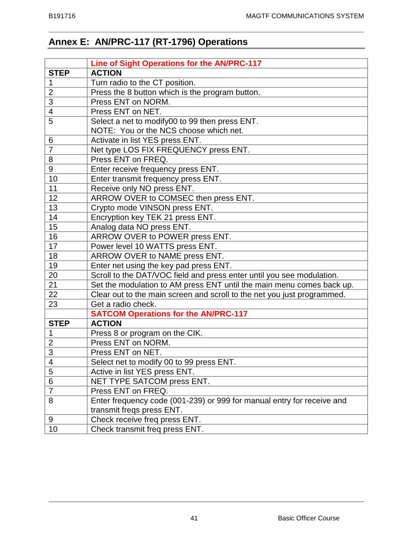
Annex E: AN/PRC-117 (RT-1796) Operations
Line of Sight Operations for the AN/PRC-117
STEP ACTION
1 Turn radio to the CT position.
2 Press the 8 button which is the program button.
3 Press ENT on NORM.
4 Press ENT on NET.
5 Select a net to modify00 to 99 then press ENT. NOTE: You or the NCS choose which net.
6 Activate in list YES press ENT.
7 Net type LOS FIX FREQUENCY press ENT.
8 Press ENT on FREQ.
9 Enter receive frequency press ENT.
10 Enter transmit frequency press ENT.
11 Receive only NO press ENT.
12 ARROW OVER to COMSEC then press ENT.
13 Crypto mode VINSON press ENT.
14 Encryption key TEK 21 press ENT.
15 Analog data NO press ENT.
16 ARROW OVER to POWER press ENT.
17 Power level 10 WATTS press ENT.
18 ARROW OVER to NAME press ENT.
19 Enter net using the key pad press ENT.
20 Scroll to the DAT/VOC field and press enter until you see modulation.
21 Set the modulation to AM press ENT until the main menu comes back up.
22 Clear out to the main screen and scroll to the net you just programmed.
23 Get a radio check.
SATCOM Operations for the AN/PRC-117
STEP ACTION
1 Press 8 or program on the CIK.
2 Press ENT on NORM.
3 Press ENT on NET.
4 Select net to modify 00 to 99 press ENT.
5 Active in list YES press ENT.
6 NET TYPE SATCOM press ENT.
7 Press ENT on FREQ.
8 Enter frequency code (001-239) or 999 for manual entry for receive and transmit freqs press ENT.
9 Check receive freq press ENT.
10 Check transmit freq press ENT.
B191716 MAGTF COMMUNICATIONS SYSTEM
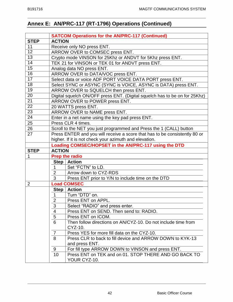
42 Basic Officer Course
Annex E: AN/PRC-117 (RT-1796) Operations (Continued)
SATCOM Operations for the AN/PRC-117 (Continued)
STEP ACTION
11 Receive only NO press ENT. 12 ARROW OVER to COMSEC press ENT. 13 Crypto mode VINSON for 25Khz or ANDVT for 5Khz press ENT. 14 TEK 21 for VINSON or TEK 01 for ANDVT press ENT. 15 Analog data NO press ENT. 16 ARROW OVER to DATA/VOC press ENT. 17 Select data or voice ADF PORT VOICE DATA PORT press ENT. 18 Select SYNC or ASYNC (SYNC is VOICE, ASYNC is DATA) press ENT. 19 ARROW OVER to SQUELCH then press ENT. 20 Digital squelch ON/OFF press ENT. (Digital squelch has to be on for 25Khz) 21 ARROW OVER to POWER press ENT. 22 20 WATTS press ENT. 23 ARROW OVER to NAME press ENT. 24 Enter in a net name using the key pad press ENT.
25 Press CLR 4 times.
26 Scroll to the NET you just programmed and Press the 1 (CALL) button
27 Press ENTER and you will receive a score that has to be consistently 80 or higher. If it is not check your azimuth and elevation.
Loading COMSEC/HOPSET in the AN/PRC-117 using the DTD
STEP ACTION
1 Prep the radio
Step Action
1 Set “FCTN” to LD.
2 Arrow down to CYZ-RDS
3 Press ENT prior to Y/N to include time on the DTD
2 Load COMSEC
Step Action
1 Turn “DTD” on.
2 Press ENT on APPL.
3 Select “RADIO” and press enter.
4 Press ENT on SEND. Then send to: RADIO.
5 Press ENT on ICOM.
6 Then follow directions on AN/CYZ-10. Do not include time from CYZ-10.
7 Press YES for more fill data on the CYZ-10.
8 Press CLR to back to fill device and ARROW DOWN to KYK-13 and press ENT.
9 For fill type ARROW DOWN to VINSON and press ENT.
10 Press ENT on TEK and on 01. STOP THERE AND GO BACK TO YOUR CYZ-10.
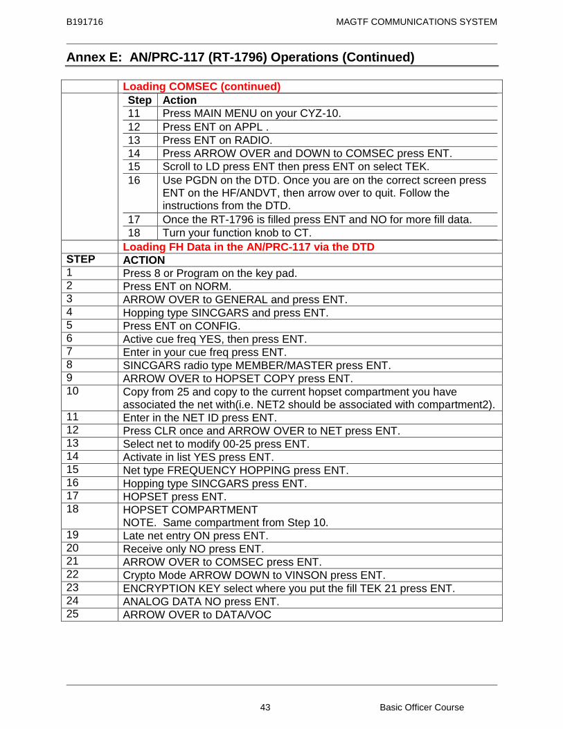
B191716 MAGTF COMMUNICATIONS SYSTEM
43 Basic Officer Course
Annex E: AN/PRC-117 (RT-1796) Operations (Continued)
Loading COMSEC (continued) Step Action
11 Press MAIN MENU on your CYZ-10.
12 Press ENT on APPL .
13 Press ENT on RADIO.
14 Press ARROW OVER and DOWN to COMSEC press ENT.
15 Scroll to LD press ENT then press ENT on select TEK.
16 Use PGDN on the DTD. Once you are on the correct screen press ENT on the HF/ANDVT, then arrow over to quit. Follow the instructions from the DTD.
17 Once the RT-1796 is filled press ENT and NO for more fill data.
18 Turn your function knob to CT.
Loading FH Data in the AN/PRC-117 via the DTD STEP ACTION 1 Press 8 or Program on the key pad. 2 Press ENT on NORM. 3 ARROW OVER to GENERAL and press ENT. 4 Hopping type SINCGARS and press ENT. 5 Press ENT on CONFIG. 6 Active cue freq YES, then press ENT. 7 Enter in your cue freq press ENT. 8 SINCGARS radio type MEMBER/MASTER press ENT. 9 ARROW OVER to HOPSET COPY press ENT. 10 Copy from 25 and copy to the current hopset compartment you have
associated the net with(i.e. NET2 should be associated with compartment2). 11 Enter in the NET ID press ENT. 12 Press CLR once and ARROW OVER to NET press ENT. 13 Select net to modify 00-25 press ENT. 14 Activate in list YES press ENT. 15 Net type FREQUENCY HOPPING press ENT. 16 Hopping type SINCGARS press ENT. 17 HOPSET press ENT. 18 HOPSET COMPARTMENT
NOTE. Same compartment from Step 10. 19 Late net entry ON press ENT. 20 Receive only NO press ENT. 21 ARROW OVER to COMSEC press ENT. 22 Crypto Mode ARROW DOWN to VINSON press ENT. 23 ENCRYPTION KEY select where you put the fill TEK 21 press ENT. 24 ANALOG DATA NO press ENT. 25 ARROW OVER to DATA/VOC
B191716 MAGTF COMMUNICATIONS SYSTEM
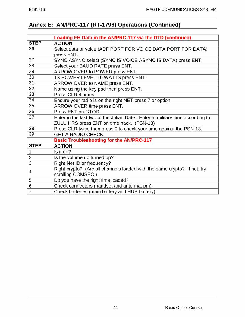
44 Basic Officer Course
Annex E: AN/PRC-117 (RT-1796) Operations (Continued)
Loading FH Data in the AN/PRC-117 via the DTD (continued) STEP ACTION 26 Select data or voice (ADF PORT FOR VOICE DATA PORT FOR DATA)
press ENT. 27 SYNC ASYNC select (SYNC IS VOICE ASYNC IS DATA) press ENT. 28 Select your BAUD RATE press ENT. 29 ARROW OVER to POWER press ENT. 30 TX POWER LEVEL 10 WATTS press ENT. 31 ARROW OVER to NAME press ENT. 32 Name using the key pad then press ENT. 33 Press CLR 4 times. 34 Ensure your radio is on the right NET press 7 or option. 35 ARROW OVER time press ENT. 36 Press ENT on GTOD 37 Enter in the last two of the Julian Date. Enter in military time according to
ZULU HRS press ENT on time hack. (PSN-13) 38 Press CLR twice then press 0 to check your time against the PSN-13. 39 GET A RADIO CHECK. Basic Troubleshooting for the AN/PRC-117 STEP ACTION
1 Is it on?
2 Is the volume up turned up?
3 Right Net ID or frequency?
4 Right crypto? (Are all channels loaded with the same crypto? If not, try scrolling COMSEC.)
5 Do you have the right time loaded?
6 Check connectors (handset and antenna, pm).
7 Check batteries (main battery and HUB battery).
B191716 MAGTF COMMUNICATIONS SYSTEM
45 Basic Officer Course
Annex F: AN/PRC-150 (RT-1694) Operations
Loading COMSEC into the AN/PRC-150 with AN/CYZ-10
STEP ACTION
1 Press ON/OFF on the AN/CYZ-10
2 Press MAIN MENU if not already there.
3 Press LETTER LOCK TO OFF
4 Press ENTER ON APPL
5 Scroll to RADIO press ENTER
6 Scroll to COMSEC press ENTER
7 Scroll to LD press ENTER
8 ENTER ON TEK
9 PGDN and press ENTER on KEY TO USE
10 XMT should show next to Key and press ENTER on QUIT
11 Connect ANCD to RT (STOP HERE) program the RT-1694
12 On RT-1694 Scroll to LD
13 FILL DEVICE: Scroll UP/DOWN to KYK-13 press ENTER
14 CRYPTO TYPE: ANDVT or KG 84
15 KEY TYPE: TEK, KEY NUMBER: 01 PRESS ENTER
16 NOW ON CYZ-10 PRESS ENTER ON CONNECT TO ANCD TO RT
17 WAIT FOR IT TO SAY PRESS LOAD ON RT
18 PRESS ENTER TO INITIATE FILL
19 FILL DONE PRESS ENT
21 MORE FILL DATA (NO)
22 Move switch out of LD position
Programming Fixed Frequency Channel in the AN/PRC-150
STEP ACTION
1 Press the 8 (PGM) button
2 Scroll to MODE press ENTER
3 Press ENTER on PRESET
4 Press ENTER on Channel
5 Select channel number to change (001) MULTIPLE CHANNELS FOR ALE
6 Enter RX frequency (1.6-59.9999Mhz)
7 Enter TX frequency (1.6-59.9999Mhz)
8 MODULATION USB
9 AGC SPEED (MED)
10 BANDWIDTH (3.0 KHZ)
11 RX ONLY (NO)
12 LIMIT MAX TRANSMIT POWER (NO)
13 ENABLE SSB SCAN (NO)
14 Press CLR 4 times to return to main screen
15 RIGHT ARROW TO KEY
16 Scroll UP/DOWN until it says TEK 01 ANDVT HF/BD or KG 84
17 CHANGE CRYPTO MODE (YES)
B191716 MAGTF COMMUNICATIONS SYSTEM
46 Basic Officer Course
Annex F: AN/PRC-150 (RT-1694) Operations (Continued)
Programming Channel for HF communications in the AN/PRC-150 (Continued)
STEP ACTION
18 Main screen should appear again in CT ANDVT-HF/BD or KG 84
19 RIGHT ARROW TO CHANNEL
20 Scroll UP/DOWN to select channel *
Programming Automatic Link Establishment (ALE)
STEP ACTION
1 HIT 8 (PGM)
2 Scroll to MODE press ENTER
3 Scroll to ALE press ENTER
4 Press ENTER on CHANNEL GROUP
5 ENTER on ADD
6 Select a GROUP # EX: 01 press ENTER
7 ENTER on ADD
8 Select Channel # EX: 1,2,3,4,5. Enter a total of 5 channels
9 CLR 3 TIMES
10 Scroll to ADDRESS
11 ADDRESS TYPE (SELF)
12 Enter on ADD
13 Name your Address 1-3 Characters EX: 001, TBS, ACO, BCO
14 Press ENTER to save
15 Add to Channel Group EX: 01 PRESS ENTER
16 ADDRESS TYPE (INDIVIDUAL)
17 ENTER on ADD
18 NAME INDIVIDUAL ADDRESSES (not yours) EX: TBS, ACO, BCO
19 ADD TO CHANNEL GROUP EX: 01
20 ASSOC SELF (SHOULD BE YOUR SELF ADDRESS) EX: 001
21 ADDRESS TYPE (NET)
22 ENTER on ADD
23 Name your Net EX: TAC, BNC, 1MD, 2MD, ALE (1-3 Characters)
24 CHANNEL GROUP EX: 01
25 ASSOC SELF (YOUR SELF ADDRESS) EX: 001, TBS, ACO
26 Scroll UP/DOWN to review press ENTER
27 Scroll UP/DOWN to ensure that both SELF ADDRESS and INDIVIDUAL ADDRESS are both NET MEMBERS.
28 Hit CLR until you are back to the ADDRESS MENU
29 Scroll to CONFIG press ENTER
30 MAX SCAN CHANNELS ( THE NUMBER OF CHANNELS IN GROUP) EX: 5
31 LISTEN BEFORE TRANSMIT (OFF)
32 KEY TO CALL (ON)
33 MAX TUNE TIME 3 SECS
B191716 MAGTF COMMUNICATIONS SYSTEM
47 Basic Officer Course
Annex F: AN/PRC-150 (RT-1694) Operations (Continued)
Automatic Link Establishment (ALE) (continued)
STEP ACTION
34 LINK TIMEOUT (OFF)
35 LINK TO ANY CALLS (OFF)
36 AMD OPERATION ENABLED
37 AMD AUTO DISPLAY ON
38 SCAN RATE (2)
39 LINK PROTECTION LEVEL 0
40 LINK PROTECTION KEY (000000000000000)
41 Pres CLR until you see the ALE screen
42 Scroll to MODEM and press ENT
43 Change the modem name to SER24
44 Press ENT until you see mode
45 Scroll to System and press ENT
46 Press ENT until you see RADIO NAME
47 Arrow up until you see ALE press ENT
48 Arrow up until you see your SELF ADDRESS press ENT
49 Arrow up until you see SER24 press ENT
50 Arrow up until you see TYPE1 press ENT
51 Arrow up until you see ANDVT BD
52 Press ENT until you see the MODE screen
53 Press 8 PRG button and the main screen will be displayed
54 Press 3(MODE) until it says ALE press ENTER
55 RIGHT ARROW TO KEY
56 Scroll UP/DOWN until it says TEK 01 ANDVT HF/BD or KG 84
57 CHANGE CRYPTO MODE (YES)
58 Main screen should appear again in CT ANDVT-HF/BD or KG 84
59 Press CLR to begin scanning
60 Key out on handset to link frequencies
NOTE: Different Crypto types offer different Modem types. The instructions above,
references setting up an ALE network with an ANDVT/BD crypto and a Serial Modem.

B191716 MAGTF COMMUNICATIONS SYSTEM
48 Basic Officer Course
Annex G: AN/PRC-152 (RT-1619) Operations
Loading AN/PRC-152 with a single channel (VULOS) frequency
STEP ACTION
1 RT can either be on PT or CT to program but CANNOT be on LD
2 Once at main screen select PGM, ENTER
3 Scroll to VULOS CONFIG, ENTER
4 Scroll to VINSON COMPATIBILITY, ENTER
5 Set to VINSON COMPATIBILITY ON, ENTER
6 CLR back to PGM menu, scroll to SYSTEM PRESETS, ENTER
7 Got to SYSTEM PRESET CONFIG, ENTER
8 SYSTEM PRESET NUMBER (enter channel number you want to config), ENTER
9 PRESET DESCRIPTION (this is a description of this net). It is NOT NEEDED to enter anything. Can be left at default.
10 PRESET WAVEFORM (select appropriate waveform ie: VULOS, HAVEQUICK, HPW). Select VULOS, ENTER
11 Next programming menu for that specific net will appear, select GENERAL CONFIG, ENTER
12 PRESET NAME (program appropriate channel name), ENTER
13 PRESET TYPE, select LOS, ENTER
14 Next RT will take you back to PRESET CONFIG menu, a checkmark will appear next to GENERAL CONFIG telling you that this portion of programming is done. Highlight FREQUENCY, ENTER
15 Input RCV FREQ, ENTER
16 RECEIVE ONLY, NO, ENTER
17 TRANSMIT FREQ, use RECEIVE FREQ, ENTER. RT will show TRANS FREQ, hit ENTER
18 RT goes back to PRESET CONFIG menu with a check next to FREQUENCY stating it has been programmed
19 Select COMSEC, ENTER
20 RT will ask for COMSEC mode, select VINSON, ENTER
21 RT will ask for CRYPTO key, select appropriate THE, ENTER
22 RT goes back to PRESET CONFIG menu with checkmark next to COMSEC
23 Scroll to TRAFFIC, ENTER
24 TRAFFIC MODE VX or DATA, ENTER
25 Next RT will scroll through defaults given by TRAFFIC MODE and Frequency Range selected, ENTER through to PRESET CONFIG menu and checkmark will appear next to TRAFFIC
26 Select TX PWR, ENTER. Select desired PWR level, ENTER. RT goes back to PRESET CONFIG MENU
27 Scroll through SQUELCH, make changes if desired other than default and hit EXIT
B191716 MAGTF COMMUNICATIONS SYSTEM
49 Basic Officer Course
Annex G: AN/PRC-152 (RT-1619) Operations (Continued)
Loading AN/PRC-152 COMSEC
STEP ACTION
1 Prep the Radio
Step Action
1 PWR on RT by turning large knob to FP (System will run self test)
2 Once at main screen, looking down from top of RT change from PT to LD
3 Radio will change to FILL menu
4 Under fill menu, select FILL, ENTER
5 Select waveform for Single Channel CT, select VULOS, ENTER
6 Select FILL device, KYK 13, ENTER
7 Go to Step 2 Load COMSEC
8 Press ENTER to initiate fill
9 Once key has transferred RT will ask what CRYPTO mode, select VINSON, ENTER
10 Key type, select TEK and set key number, ENTER
11 RT will ask for classification of key. Select what classification the key is, ENTER
12 RT will say completing fill and will then ask you if you need to LD another key. If yes it will kick you back to step 5. If no, RT will kick you back to FILL menu. From there roll small knob to CT (These steps apply to all Single Channel Programming IE: VHF, UHF, SATCOM VX and DATA) Available selections for waveform are SINCGARS for FREQ HOPPING, VULOS for VHF and UHF LOS and HPW for SATCOM DATA
2 Load COMSEC
Step Action
1 Turn “DTD” on.
2 Select “RADIO” and press enter.
3 Select “COMSEC” and press enter.
4 Select “LD” and press enter.
5 Select desired segment by paging up or down and press enter at desired segment.
6 “XMIT” will show on the screen to the right of the segment.
7 Arrow over to “QUIT” and press enter.
8 Connect DTD to RT-1619 and arrow down.
9 DTD will display “SENDING TEK.”
10 DTD will display “PRESS LOAD ON RT.”
11 Go to step 8 of radio setup
Loading COMSEC/HOPSET in the AN/PRC-152 using the DTD
STEP ACTION
1 Set RT knobs to FP and FILL
2 Highlight FILL, ENTER
3 Scroll to SINCGARS, ENTER
B191716 MAGTF COMMUNICATIONS SYSTEM
50 Basic Officer Course
Annex G: AN/PRC-152 (RT-1619) Operations (Continued)
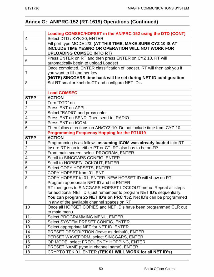
Loading COMSEC/HOPSET in the AN/PRC-152 using the DTD (CONT)
4 Select DTD / KYK 20, ENTER
5 Fill port type MODE 2/3, (AT THIS TIME, MAKE SURE CYZ 10 IS AT INCLUDE TIME YES/NO OR OPERATION WILL NOT WORK FOR UPLOADING COMSEC INTO RT)
6 Press ENTER on RT and then press ENTER on CYZ 10. RT will automatically begin to upload Loadset
7 Once completed, ENTER classification of loadset. RT will then ask you if you want to fill another key. (NOTE) SINCGARS time hack will be set during NET ID configuration
8 Set RT smaller knob to CT and configure NET ID’s
Load COMSEC
STEP ACTION
1 Turn “DTD” on.
2 Press ENT on APPL.
3 Select “RADIO” and press enter.
4 Press ENT on SEND. Then send to: RADIO.
5 Press ENT on ICOM.
6 Then follow directions on AN/CYZ-10. Do not include time from CYZ-10.
Programming Frequency Hopping for the RT1619
STEP ACTION
1 Programming is as follows assuming ICOM was already loaded into RT
2 Insure RT is on in either PT or CT. RT also has to be on FP
3 From main screen, select PROGRAM, ENTER
4 Scroll to SINCGARS CONFIG, ENTER
5 Scroll to HOPSET/LOCKOUT, ENTER
6 Select COPY HOPSETS, ENTER
7 COPY HOPSET from 01, ENT
8 COPY HOPSET to 01, ENTER. NEW HOPSET ID will show on RT. Program appropriate NET ID and hit ENTER
9 RT then goes to SINCGARS HOPSET LOCKOUT menu. Repeat all steps for additional NET ID’s just remember to program NET ID’s sequentially. You can program 25 NET ID’s on PRC 152. Net ID’s can be programmed in any of the available channel spaces on RT
10 Once all HOPSET COPIES and NET ID’s have been programmed CLR out to main menu
11 Select PROGRAMMING MENU, ENTER
12 Select SYSTEM PRESET CONFIG, ENTER
13 Select appropriate NET for NET ID, ENTER
14 PRESET DESCRIPTION (leave as default), ENTER
15 PERSET WAVEFORM, select SINCGARS, ENTER
16 OP MODE, select FREQUENCY HOPPING, ENTER
17 PRESET NAME (type in channel name), ENTER
18 CRYPTO TEK 01, ENTER (TEK 01 WILL WORK for all NET ID’s)
B191716 MAGTF COMMUNICATIONS SYSTEM
51 Basic Officer Course
Annex G: AN/PRC-152 (RT-1619) Operations (Continued)
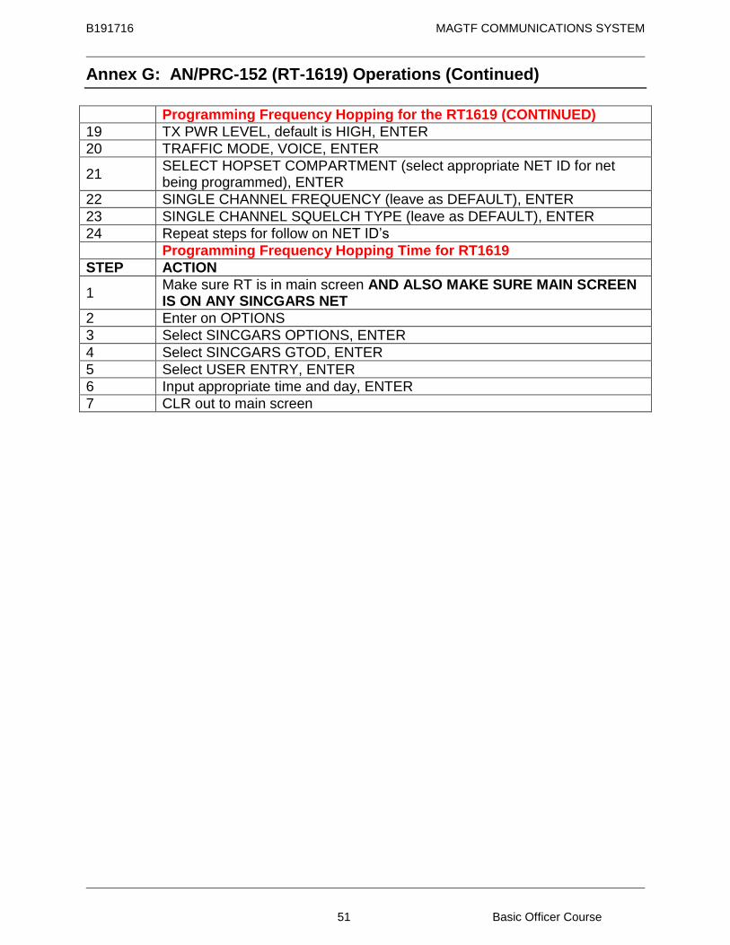
Programming Frequency Hopping for the RT1619 (CONTINUED)
19 TX PWR LEVEL, default is HIGH, ENTER
20 TRAFFIC MODE, VOICE, ENTER
21 SELECT HOPSET COMPARTMENT (select appropriate NET ID for net being programmed), ENTER
22 SINGLE CHANNEL FREQUENCY (leave as DEFAULT), ENTER
23 SINGLE CHANNEL SQUELCH TYPE (leave as DEFAULT), ENTER
24 Repeat steps for follow on NET ID’s
Programming Frequency Hopping Time for RT1619
STEP ACTION
1 Make sure RT is in main screen AND ALSO MAKE SURE MAIN SCREEN IS ON ANY SINCGARS NET
2 Enter on OPTIONS
3 Select SINCGARS OPTIONS, ENTER
4 Select SINCGARS GTOD, ENTER
5 Select USER ENTRY, ENTER
6 Input appropriate time and day, ENTER
7 CLR out to main screen
B191716 MAGTF COMMUNICATIONS SYSTEM
52 Basic Officer Course
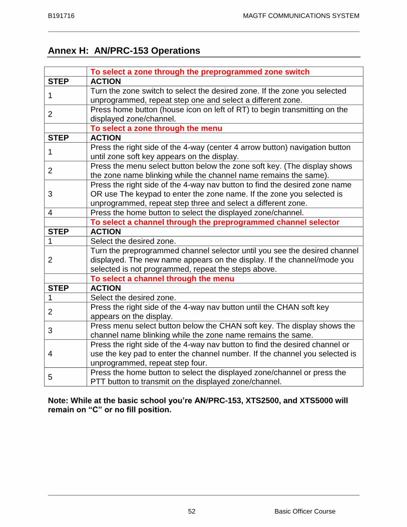
Annex H: AN/PRC-153 Operations
To select a zone through the preprogrammed zone switch
STEP ACTION
1 Turn the zone switch to select the desired zone. If the zone you selected unprogrammed, repeat step one and select a different zone.
2 Press home button (house icon on left of RT) to begin transmitting on the displayed zone/channel.
To select a zone through the menu
STEP ACTION
1 Press the right side of the 4-way (center 4 arrow button) navigation button until zone soft key appears on the display.
2 Press the menu select button below the zone soft key. (The display shows the zone name blinking while the channel name remains the same).
3 Press the right side of the 4-way nav button to find the desired zone name OR use The keypad to enter the zone name. If the zone you selected is unprogrammed, repeat step three and select a different zone.
4 Press the home button to select the displayed zone/channel.
To select a channel through the preprogrammed channel selector
STEP ACTION
1 Select the desired zone.
2 Turn the preprogrammed channel selector until you see the desired channel displayed. The new name appears on the display. If the channel/mode you selected is not programmed, repeat the steps above.
To select a channel through the menu
STEP ACTION
1 Select the desired zone.
2 Press the right side of the 4-way nav button until the CHAN soft key appears on the display.
3 Press menu select button below the CHAN soft key. The display shows the channel name blinking while the zone name remains the same.
4 Press the right side of the 4-way nav button to find the desired channel or use the key pad to enter the channel number. If the channel you selected is unprogrammed, repeat step four.
5 Press the home button to select the displayed zone/channel or press the PTT button to transmit on the displayed zone/channel.
Note: While at the basic school you’re AN/PRC-153, XTS2500, and XTS5000 will remain on “C” or no fill position.
B191716 MAGTF COMMUNICATIONS SYSTEM
53 Basic Officer Course
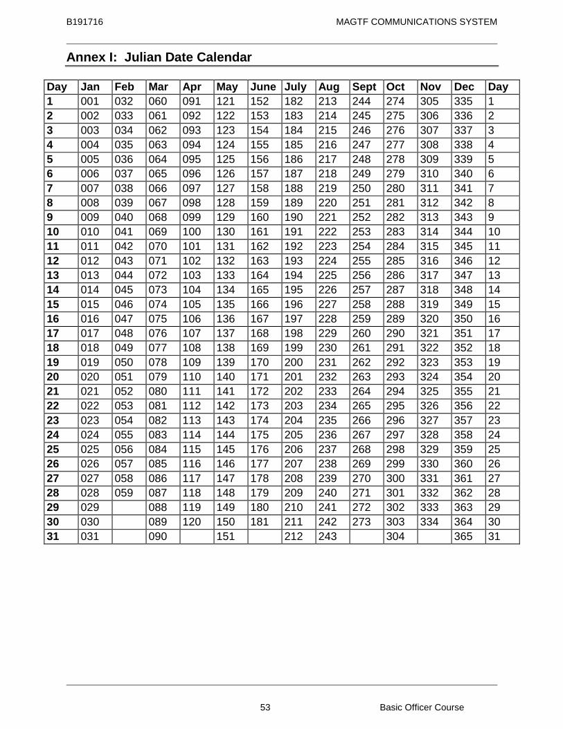
Annex I: Julian Date Calendar
Day Jan Feb Mar Apr May June July Aug Sept Oct Nov Dec Day
1 001 032 060 091 121 152 182 213 244 274 305 335 1
2 002 033 061 092 122 153 183 214 245 275 306 336 2
3 003 034 062 093 123 154 184 215 246 276 307 337 3
4 004 035 063 094 124 155 185 216 247 277 308 338 4
5 005 036 064 095 125 156 186 217 248 278 309 339 5
6 006 037 065 096 126 157 187 218 249 279 310 340 6
7 007 038 066 097 127 158 188 219 250 280 311 341 7
8 008 039 067 098 128 159 189 220 251 281 312 342 8
9 009 040 068 099 129 160 190 221 252 282 313 343 9
10 010 041 069 100 130 161 191 222 253 283 314 344 10
11 011 042 070 101 131 162 192 223 254 284 315 345 11
12 012 043 071 102 132 163 193 224 255 285 316 346 12
13 013 044 072 103 133 164 194 225 256 286 317 347 13
14 014 045 073 104 134 165 195 226 257 287 318 348 14
15 015 046 074 105 135 166 196 227 258 288 319 349 15
16 016 047 075 106 136 167 197 228 259 289 320 350 16
17 017 048 076 107 137 168 198 229 260 290 321 351 17
18 018 049 077 108 138 169 199 230 261 291 322 352 18
19 019 050 078 109 139 170 200 231 262 292 323 353 19
20 020 051 079 110 140 171 201 232 263 293 324 354 20
21 021 052 080 111 141 172 202 233 264 294 325 355 21
22 022 053 081 112 142 173 203 234 265 295 326 356 22
23 023 054 082 113 143 174 204 235 266 296 327 357 23
24 024 055 083 114 144 175 205 236 267 297 328 358 24
25 025 056 084 115 145 176 206 237 268 298 329 359 25
26 026 057 085 116 146 177 207 238 269 299 330 360 26
27 027 058 086 117 147 178 208 239 270 300 331 361 27
28 028 059 087 118 148 179 209 240 271 301 332 362 28
29 029 088 119 149 180 210 241 272 302 333 363 29
30 030 089 120 150 181 211 242 273 303 334 364 30
31 031 090 151 212 243 304 365 31
B191716 MAGTF COMMUNICATIONS SYSTEM
54 Basic Officer Course
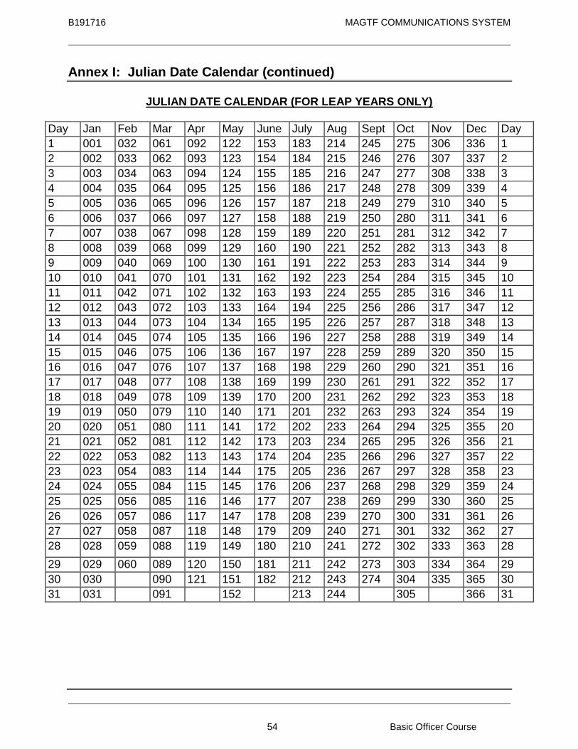
Annex I: Julian Date Calendar (continued)
JULIAN DATE CALENDAR (FOR LEAP YEARS ONLY)
Day Jan Feb Mar Apr May June July Aug Sept Oct Nov Dec Day
1 001 032 061 092 122 153 183 214 245 275 306 336 1
2 002 033 062 093 123 154 184 215 246 276 307 337 2
3 003 034 063 094 124 155 185 216 247 277 308 338 3
4 004 035 064 095 125 156 186 217 248 278 309 339 4
5 005 036 065 096 126 157 187 218 249 279 310 340 5
6 006 037 066 097 127 158 188 219 250 280 311 341 6
7 007 038 067 098 128 159 189 220 251 281 312 342 7
8 008 039 068 099 129 160 190 221 252 282 313 343 8
9 009 040 069 100 130 161 191 222 253 283 314 344 9
10 010 041 070 101 131 162 192 223 254 284 315 345 10
11 011 042 071 102 132 163 193 224 255 285 316 346 11
12 012 043 072 103 133 164 194 225 256 286 317 347 12
13 013 044 073 104 134 165 195 226 257 287 318 348 13
14 014 045 074 105 135 166 196 227 258 288 319 349 14
15 015 046 075 106 136 167 197 228 259 289 320 350 15
16 016 047 076 107 137 168 198 229 260 290 321 351 16
17 017 048 077 108 138 169 199 230 261 291 322 352 17
18 018 049 078 109 139 170 200 231 262 292 323 353 18
19 019 050 079 110 140 171 201 232 263 293 324 354 19
20 020 051 080 111 141 172 202 233 264 294 325 355 20
21 021 052 081 112 142 173 203 234 265 295 326 356 21
22 022 053 082 113 143 174 204 235 266 296 327 357 22
23 023 054 083 114 144 175 205 236 267 297 328 358 23
24 024 055 084 115 145 176 206 237 268 298 329 359 24
25 025 056 085 116 146 177 207 238 269 299 330 360 25
26 026 057 086 117 147 178 208 239 270 300 331 361 26
27 027 058 087 118 148 179 209 240 271 301 332 362 27
28 028 059 088 119 149 180 210 241 272 302 333 363 28
29 029 060 089 120 150 181 211 242 273 303 334 364 29
30 030 090 121 151 182 212 243 274 304 335 365 30
31 031 091 152 213 244 305 366 31
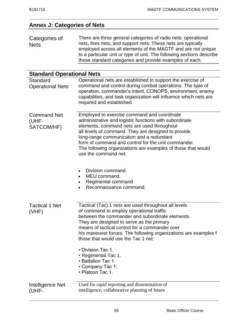
B191716 MAGTF COMMUNICATIONS SYSTEM
55 Basic Officer Course
Annex J: Categories of Nets
Categories of Nets
There are three general categories of radio nets: operational nets, fires nets, and support nets. These nets are typically employed across all elements of the MAGTF and are not unique to a particular unit or type of unit. The following sections describe those standard categories and provide examples of each.
Standard Operational Nets Standard Operational Nets
Operational nets are established to support the exercise of command and control during combat operations. The type of operation, commander’s intent, CONOPS, environment, enemy capabilities, and task organization will influence which nets are required and established.
Command Net (UHF-SATCOM/HF)
Employed to exercise command and coordinate administrative and logistic functions with subordinate elements, command nets are used throughout all levels of command. They are designed to provide long-range communication and a redundant form of command and control for the unit commander. The following organizations are examples of those that would use the command net:
Division command. MEU command. Regimental command Reconnaissance command.
Tactical 1 Net (VHF)
Tactical (Tac) 1 nets are used throughout all levels of command to employ operational traffic between the commander and subordinate elements. They are designed to serve as the primary means of tactical control for a commander over his maneuver forces. The following organizations are examples f those that would use the Tac 1 net: • Division Tac 1. • Regimental Tac 1. • Battalion Tac 1. • Company Tac 1. • Platoon Tac 1.
Intelligence Net (UHF-
Used for rapid reporting and dissemination of
intelligence, collaborative planning of future
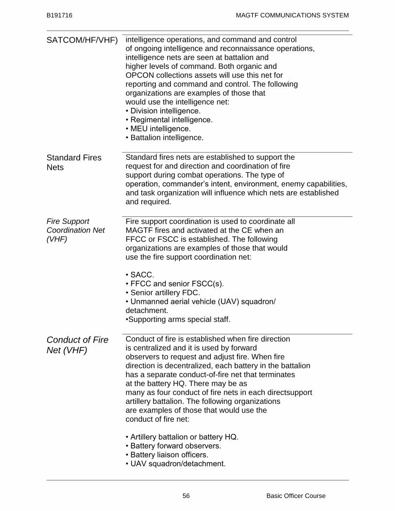
B191716 MAGTF COMMUNICATIONS SYSTEM
56 Basic Officer Course
SATCOM/HF/VHF) intelligence operations, and command and control of ongoing intelligence and reconnaissance operations, intelligence nets are seen at battalion and higher levels of command. Both organic and OPCON collections assets will use this net for reporting and command and control. The following organizations are examples of those that would use the intelligence net: • Division intelligence. • Regimental intelligence. • MEU intelligence. • Battalion intelligence.
Standard Fires Nets
Standard fires nets are established to support the request for and direction and coordination of fire support during combat operations. The type of operation, commander’s intent, environment, enemy capabilities, and task organization will influence which nets are established and required.
Fire Support Coordination Net (VHF)
Fire support coordination is used to coordinate all MAGTF fires and activated at the CE when an FFCC or FSCC is established. The following organizations are examples of those that would use the fire support coordination net: • SACC. • FFCC and senior FSCC(s). • Senior artillery FDC. • Unmanned aerial vehicle (UAV) squadron/ detachment. •Supporting arms special staff.
Conduct of Fire Net (VHF)
Conduct of fire is established when fire direction is centralized and it is used by forward observers to request and adjust fire. When fire direction is decentralized, each battery in the battalion has a separate conduct-of-fire net that terminates at the battery HQ. There may be as many as four conduct of fire nets in each directsupport artillery battalion. The following organizations are examples of those that would use the conduct of fire net: • Artillery battalion or battery HQ. • Battery forward observers. • Battery liaison officers. • UAV squadron/detachment.
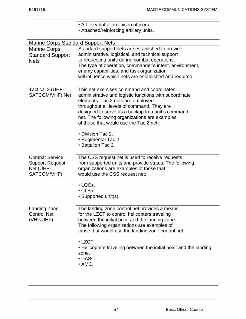
B191716 MAGTF COMMUNICATIONS SYSTEM
57 Basic Officer Course
• Artillery battalion liaison officers. • Attached/reinforcing artillery units.
Marine Corps Standard Support Nets Marine Corps Standard Support Nets
Standard support nets are established to provide administrative, logistical, and technical support to requesting units during combat operations. The type of operation, commander’s intent, environment, enemy capabilities, and task organization will influence which nets are established and required.
Tactical 2 (UHF-SATCOM/VHF) Net
This net exercises command and coordinates administrative and logistic functions with subordinate elements. Tac 2 nets are employed throughout all levels of command. They are designed to serve as a backup to a unit’s command net. The following organizations are examples of those that would use the Tac 2 net: • Division Tac 2. • Regimental Tac 2. • Battalion Tac 2.
Combat Service Support Request Net (UHF-SATCOM/VHF)
The CSS request net is used to receive requests from supported units and provide status. The following organizations are examples of those that would use the CSS request net: • LOCs. • CLBs. • Supported unit(s).
Landing Zone Control Net (VHF/UHF)
The landing zone control net provides a means for the LZCT to control helicopters traveling between the initial point and the landing zone. The following organizations are examples of those that would use the landing zone control net: • LZCT. • Helicopters traveling between the initial point and the landing zone. • DASC. • AMC.