Embed Size (px)
Citation preview
1
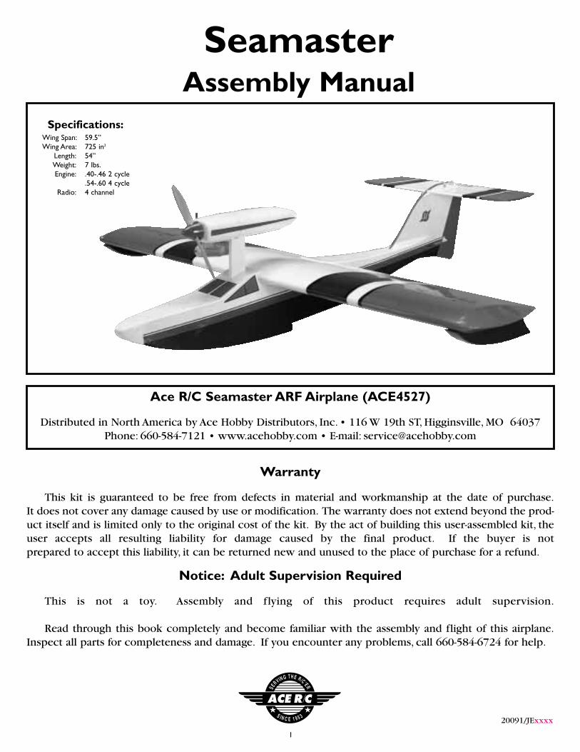
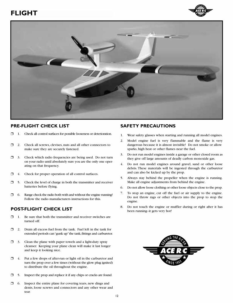
Ace R/C Seamaster ARF Airplane (ACE4527)
Distributed in North America by Ace Hobby Distributors, Inc. • 116 W 19th ST, Higginsville, MO 64037Phone: 660-584-7121 • www.acehobby.com • E-mail: [email protected]
SeamasterAssembly Manual
Wing Span: 59.5”Wing Area: 725 in2
Length: 54”Weight: 7 lbs.Engine: .40-.46 2 cycle
.54-.60 4 cycleRadio: 4 channel
Specifications:
Warranty
This kit is guaranteed to be free from defects in material and workmanship at the date of purchase.It does not cover any damage caused by use or modification. The warranty does not extend beyond the prod-uct itself and is limited only to the original cost of the kit. By the act of building this user-assembled kit, theuser accepts all resulting liability for damage caused by the final product. If the buyer is not prepared to accept this liability, it can be returned new and unused to the place of purchase for a refund.
20091/JExxxx
Notice: Adult Supervision Required
This is not a toy. Assembly and flying of this product requires adult supervision.
Read through this book completely and become familiar with the assembly and flight of this airplane.Inspect all parts for completeness and damage. If you encounter any problems, call 660-584-6724 for help.
2
INTRODUCTION
PRE-ASSEMBLY NOTES
Initially introduced to the hobby market in the 1980's, the Seamaster 40 has remained the most recogniz-able amphibious model airplane in the world. Many thousands of these models have been flown over theyears, so rest assured you have obtained the best flying amphibian on the market.
Although the plane looks bigger, a good .40-.45 two cycle or .54-.60 four cycle flies the plane nicely; don'tbe tempted to put a bigger engine on it; the airframe is not stressed for it. Realize the Seamaster is not a pat-tern ship; it is a mildly aerobatic sport ship designed for pleasing, predictable performance off both land andwater.
Before beginning the assembly read the instructions thoroughly to give an understanding of the sequenceof steps and a general awareness of the recommended assembly procedures.
By following these instructions carefully and referring to the corresponding pictures, the assembly of yourmodel will be both enjoyable and rewarding. The result will be a well built, easy to assemble A.R.F. model,which you will be proud to display and also provide you considerable enjoyment.
If you are not an experienced R/C pilot,plan to have a fully competent pilot check your completed modeland help you with your first flights. Even though we have tried to provide you with a very thorough instruc-tion manual, R/C models are rather complicated and an experienced modeler can quickly check over yourmodel to help make sure your first flights are successful. Your Seamaster is designed for intermediate toadvanced pilots.
Before you begin, check the entire contents of your kit against the parts list and photos to make sure thatno parts are missing or damaged. This will also help you to become familiar with each component of yourplane. If you find that any of the parts are either missing or damaged, please contact Ace Hobby Distributors,Inc., Customer Service (660-584-6704) immediately for replacements.
Trial fit each part before gluing it in place. Make sure you are using the correct part and that it fits wellbefore assembling. No amount of glue can make up for a poor-fitting part.
3
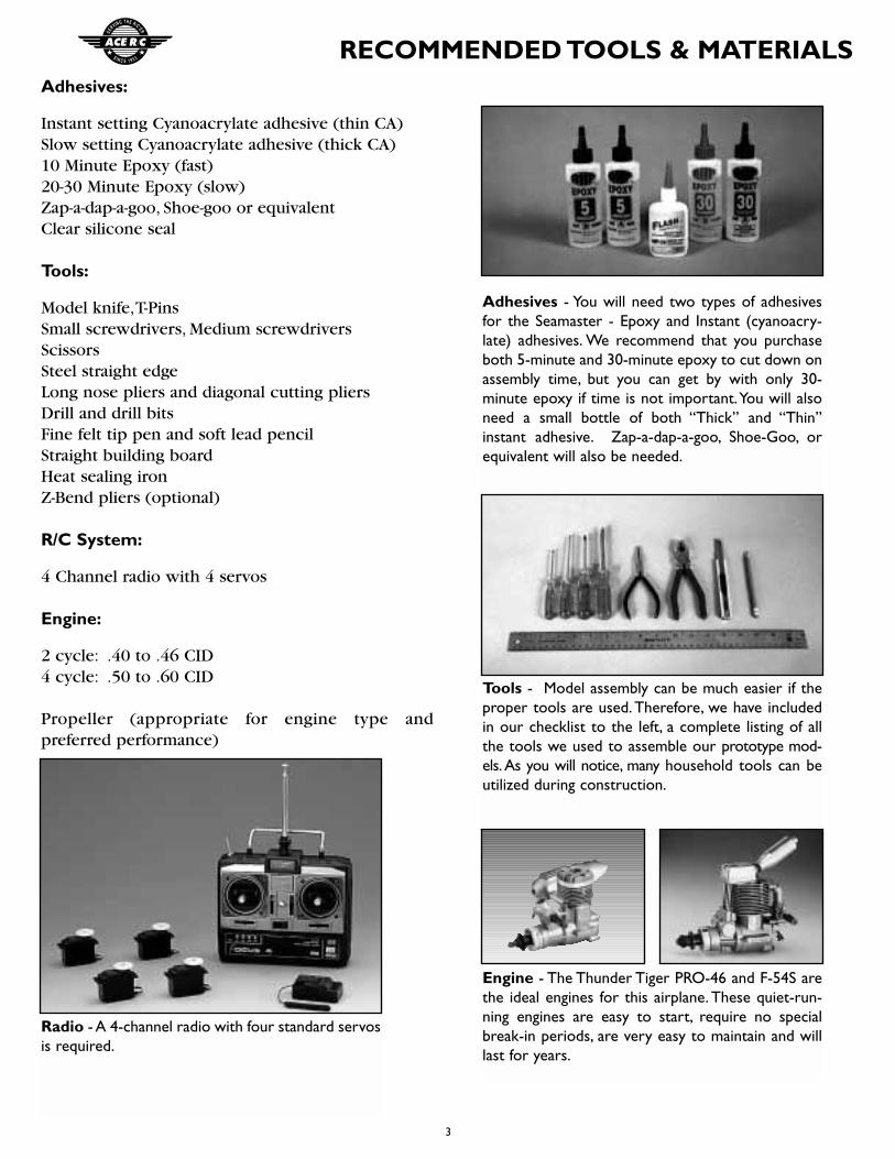
RECOMMENDED TOOLS & MATERIALSAdhesives:
Instant setting Cyanoacrylate adhesive (thin CA)Slow setting Cyanoacrylate adhesive (thick CA)10 Minute Epoxy (fast)20-30 Minute Epoxy (slow)Zap-a-dap-a-goo, Shoe-goo or equivalentClear silicone seal
Tools:
Model knife,T-PinsSmall screwdrivers, Medium screwdriversScissorsSteel straight edge Long nose pliers and diagonal cutting pliersDrill and drill bitsFine felt tip pen and soft lead pencilStraight building boardHeat sealing ironZ-Bend pliers (optional)
R/C System:
4 Channel radio with 4 servos
Engine:
2 cycle: .40 to .46 CID4 cycle: .50 to .60 CID
Propeller (appropriate for engine type and preferred performance)
Adhesives - You will need two types of adhesivesfor the Seamaster - Epoxy and Instant (cyanoacry-late) adhesives. We recommend that you purchaseboth 5-minute and 30-minute epoxy to cut down onassembly time, but you can get by with only 30-minute epoxy if time is not important.You will alsoneed a small bottle of both “Thick” and “Thin”instant adhesive. Zap-a-dap-a-goo, Shoe-Goo, orequivalent will also be needed.
Tools - Model assembly can be much easier if theproper tools are used.Therefore, we have includedin our checklist to the left, a complete listing of allthe tools we used to assemble our prototype mod-els.As you will notice, many household tools can beutilized during construction.
Engine - The Thunder Tiger PRO-46 and F-54S arethe ideal engines for this airplane. These quiet-run-ning engines are easy to start, require no specialbreak-in periods, are very easy to maintain and willlast for years.
Radio - A 4-channel radio with four standard servosis required.
4
PARTS DRAWINGS
Servo Rail (2)
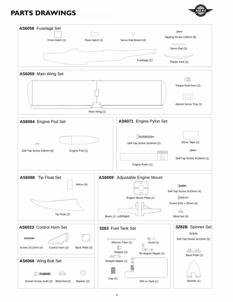
AS6058 Fuselage Set
Front Hatch (1) Rear Hatch (1) Servo Rail Mount (4)Tapping Screw 2x8mm (8)
Fuselage (1)
Aileron Servo Tray (1)
AS6059 Main Wing Set
Main Wing (1)
Torque Rod Horn (2)
Engine Pod (1)
AS6064 Engine Pod Set
Self-Tap Screw 2x8mm (8)
Self-Tap Screw 4x16mm (1)
AS6071 Engine Pylon Set
Self-Tap Screw 3x34mm (2) Servo Tape (1)
Engine Pylon (1)
Tip Float (2)
AS6068 Tip Float Set
Velcro (4)
AS6069 Adjustable Engine Mount
Engine Mount Plate (1)
Beam (2, Left/Right)
Self-Tap Screw 3x15mm (4)
Screw 6/32 x 25mm (4)
Blind Nut (4)
AS6023 Control Horn Set
Back Plate (2)Screw 2x12mm (4) Control Horn (2)
3263 Fuel Tank Set
300 cc Tank (1)
Silicone Tube (1) Clunk (1)
Stopper (1) 90-degree Nipple (1)
Straight Nipple (1)
Cap (1)Spinner (1)
3282B Spinner Set
Self-Tap Screw 3x12mm (2)
Back Plate (1)
AS6066 Wing Bolt Set
Socket Screw 4x40 (2) Blind Nut (2) Washer (2)
Plastic Keel (1)
5
PARTS DRAWINGS
Self-Tap Screw
2x8mm (4)
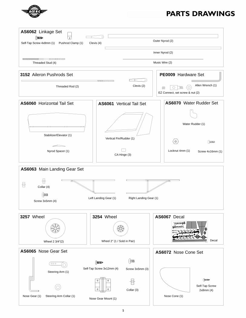
AS6062 Linkage Set
Inner Nyrod (2)
Music Wire (2)
Self-Tap Screw 4x8mm (1)
Self-Tap Screw 3x12mm (4)
Pushrod Clamp (1)
Allen Wrench (1)
EZ Connect, set screw & nut (2)
Clevis (4)Outer Nyrod (2)
Threaded Stud (4)
AS6060 Horizontal Tail Set
Stabilizer/Elevator (1)
Nyrod Spacer (1)
AS6061 Vertical Tail Set
Vertical Fin/Rudder (1)
CA Hinge (3)
AS6070 Water Rudder Set
Screw 4x16mm (1)
Water Rudder (1)
Locknut 4mm (1)
Right Landing Gear (1)
AS6063 Main Landing Gear Set
Collar (4)
Screw 3x5mm (4)Left Landing Gear (1)
3257 Wheel
Wheel 2 3/4"(2)
3254 Wheel
Wheel 2" (1 / Sold in Pair)
AS6067 Decal
Decal
AS6065 Nose Gear Set
Collar (3)
Nose Gear (1)
Steering Arm (1)Screw 3x5mm (3)
Steering Arm Collar (1)Nose Gear Mount (1)
AS6072 Nose Cone Set
Nose Cone (1)
3152 Aileron Pushrods Set PE0009 Hardware Set
Threaded Rod (2) Clevis (2)
6
WING ASSEMBLY/ENGINE POD ASSEMBLY
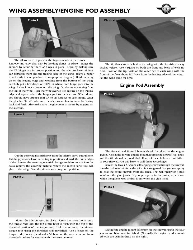
The tip floats are attached to the wing with the furnished stickybacked Velcro. Use a square on both the front and back of each tipfloat. Position the tip floats on the outer bay of each wing with thefront of the float about 1/2" back from the leading edge of the wing.Set the wing aside for now.
Engine Pod Assembly
The firewall and firewall braces should be glued to the enginepylon. Also, holes for the engine mount, reinforcing screws, fuel lines,and throttle should be pre-drilled. If any of these holes are not drilledin your firewall, you will have to drill them accordingly.
Screw the two 4 X 35mm self tapping screws through the firewallinto the pylon to reinforce the joint. It is suggested that you use epoxyto coat the entire firewall, front and back. This will fuelproof it plusreinforce the glue joints. If you get epoxy in the holes, wipe it outwhile the glue is wet, or drill it out when the glue is set.
Secure the engine mount assembly on the firewall using the fourscrews and blind nuts furnished. (Normally, the engine is side-mount-ed with the cylinder head on the right.)
The ailerons are in place with hinges already in their slots.Remove any tape that may be holding things in place. Hinge theailerons by securing the "CA" hinges in place. Begin by making surethe CA hinges are in proper position and the ailerons have minimalgap between them and the trailing edge of the wing. (Have a papertowel ready in case you have to mop up excess glue.) Hold the wingup on the leading edge and, working from the bottom of the wing,carefully put a few drops of THIN CA where each hinge goes into thewing. It should wick down into the wing. Do the same, working fromthe top of the wing. Turn the wing over so it is resting on the trailingedge and repeat where the hinges go into the ailerons. When done,you should have applied thin CA to all surfaces of each hinge. Afterthe glue has "fired", make sure the ailerons are free to move by flexingback and forth. Also make sure the glue joint is secure by tugging onthe ailerons.
Cut the covering material away from the aileron servo cutout hole.Put the plywood aileron servo tray in position and mark the outer edgesof the plate on the covering material. Being careful to not cut into thebalsa, remove the covering material where the aileron servo tray willglue to the wing. Glue the aileron servo tray into position.
Mount the aileron servo in place. Screw the nylon horns ontothe torque rods until the top of the horn is flush with the top of thethreaded portion of the torque rod. Link the servo to the ailerontorque rods using the threaded rods furnished. Use a clevis on thetorque rod (threaded) end and a "Z" bend on the servo arm end (non-threaded). Adjust for neutral with the servo centered.
Photo 1
Photo 2
Photo 3
Photo 6
Photo 5
Photo 4
7
ENGINE POD ASSEMBLY/FUSELAGE ASSEMBLY
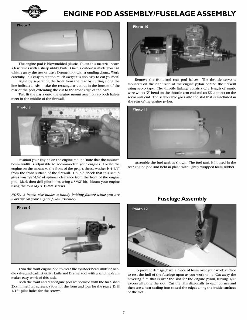
The engine pod is blowmolded plastic. To cut this material, scorea few times with a sharp utility knife. Once a cut-out is made, you canwhittle away the rest or use a Dremel tool with a sanding drum.. Workcarefully. It is easy to cut too much away; it is also easy to cut yourself.
Begin by separating the front from the rear by cutting along theline indicated. Also make the rectangular cutout in the bottom of therear of the pod, extending the cut to the front edge of the part.
Test fit the parts onto the engine mount assembly so both halvesmeet in the middle of the firewall.
Position your engine on the engine mount (note that the mount'sbeam width is adjustable to accommodate your engine). Locate theengine on the mount so the front of the prop's thrust washer is 4 1/4"from the front surface of the firewall. Double check that this set-upgives you 1/8”-1/4” of spinner clearance from the front of the enginepod. Mark then drill pilot holes using a 3/32" bit. Mount your engineusing the four M3 X 15mm screws.
NOTE: A bench vise makes a handy holding fixture while you areworking on your engine pylon assembly.
Trim the front engine pod to clear the cylinder head,muffler,nee-dle valve,and carb. A utility knife and Dremel tool with a sanding drummakes easy work of this task.
Both the front and rear engine pod are secured with the furnished2X8mm self tap screws. (Four for the front and four for the rear.) Drill1/16" pilot holes for the screws.
Remove the front and rear pod halves. The throttle servo ismounted on the right side of the engine pylon behind the firewallusing servo tape. The throttle linkage consists of a length of musicwire with a “Z”bend on the throttle arm end and an EZ connect on theservo arm end. The servo cable goes into the slot that is machined inthe rear of the engine pylon.
Assemble the fuel tank as shown. The fuel tank is housed in therear engine pod and held in place with lightly wrapped foam rubber.
Fuselage Assembly
To prevent damage, have a piece of foam over your work surfaceto rest the hull of the fuselage upon as you work on it. Cut away thecovering film that is over the slot for the engine pylon, leaving 1/4”excess all along the slot. Cut the film diagonally to each corner andthen use a heat sealing iron to seal the edges along the inside surfacesof the slot.
Photo 7
Photo 8
Photo 9 Photo 12
Photo 11
Photo 10
8
FUSELAGE ASSEMBLY
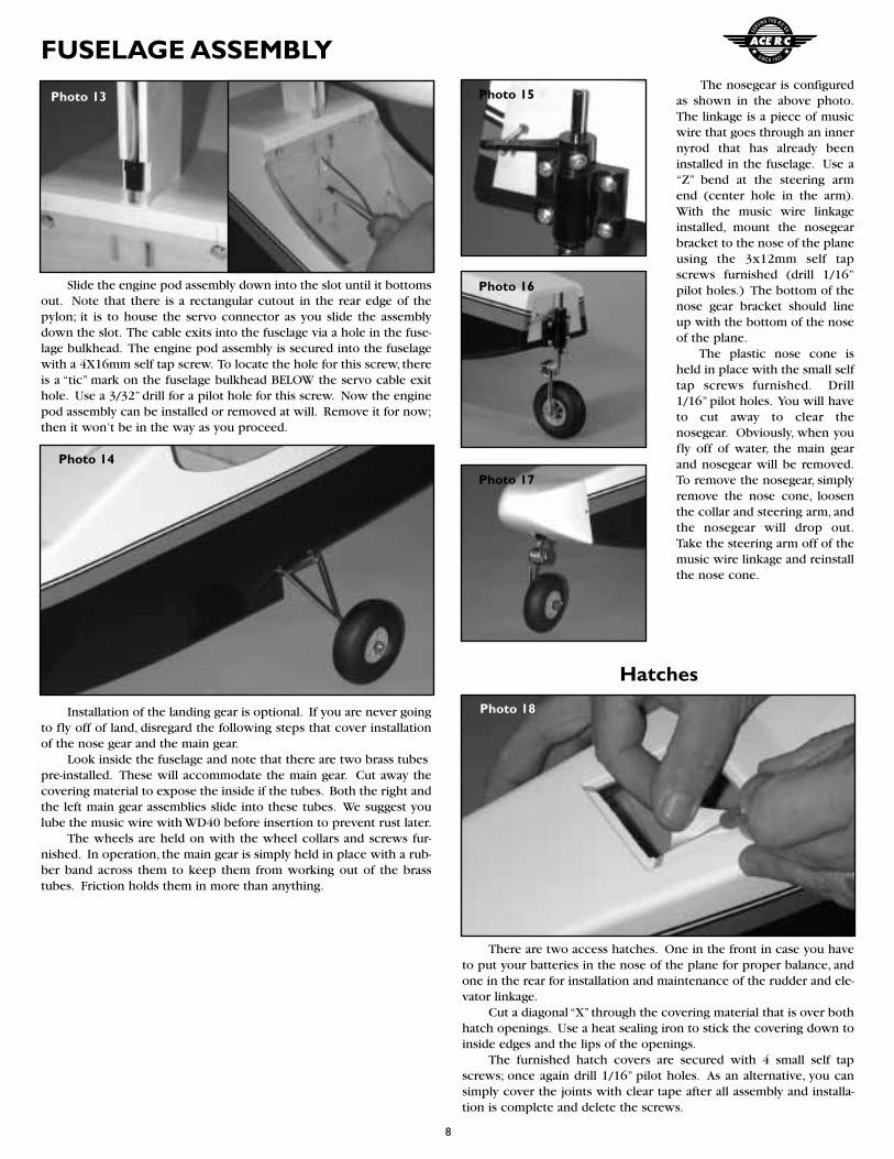
Slide the engine pod assembly down into the slot until it bottomsout. Note that there is a rectangular cutout in the rear edge of thepylon; it is to house the servo connector as you slide the assemblydown the slot. The cable exits into the fuselage via a hole in the fuse-lage bulkhead. The engine pod assembly is secured into the fuselagewith a 4X16mm self tap screw. To locate the hole for this screw, thereis a “tic” mark on the fuselage bulkhead BELOW the servo cable exithole. Use a 3/32” drill for a pilot hole for this screw. Now the enginepod assembly can be installed or removed at will. Remove it for now;then it won’t be in the way as you proceed.
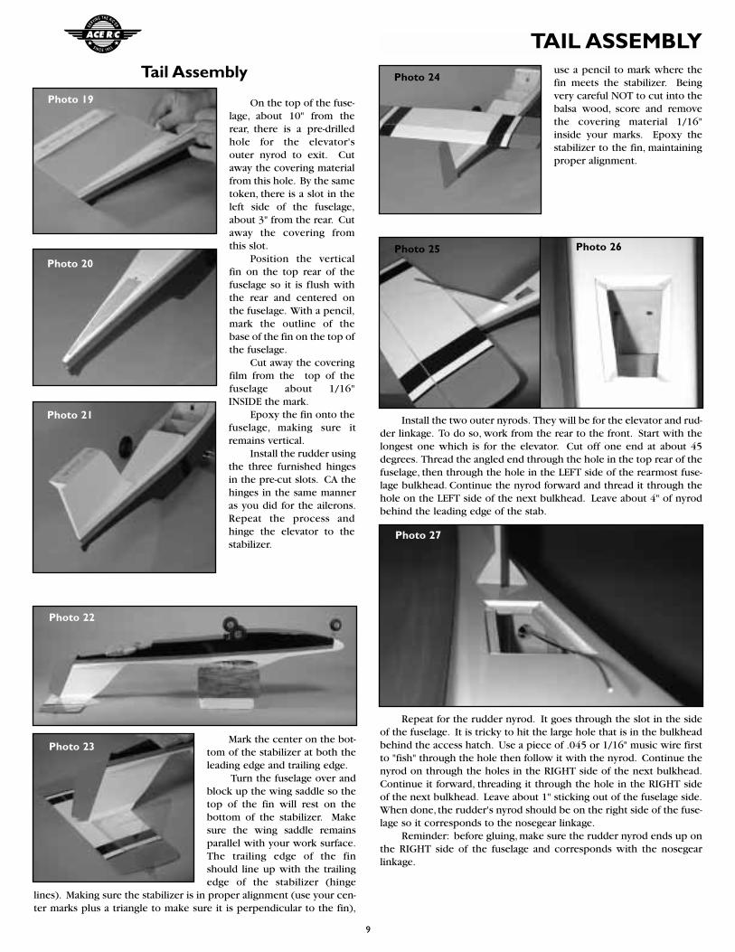
Installation of the landing gear is optional. If you are never goingto fly off of land, disregard the following steps that cover installationof the nose gear and the main gear.
Look inside the fuselage and note that there are two brass tubespre-installed. These will accommodate the main gear. Cut away thecovering material to expose the inside if the tubes. Both the right andthe left main gear assemblies slide into these tubes. We suggest youlube the music wire with WD40 before insertion to prevent rust later.
The wheels are held on with the wheel collars and screws fur-nished. In operation, the main gear is simply held in place with a rub-ber band across them to keep them from working out of the brasstubes. Friction holds them in more than anything.
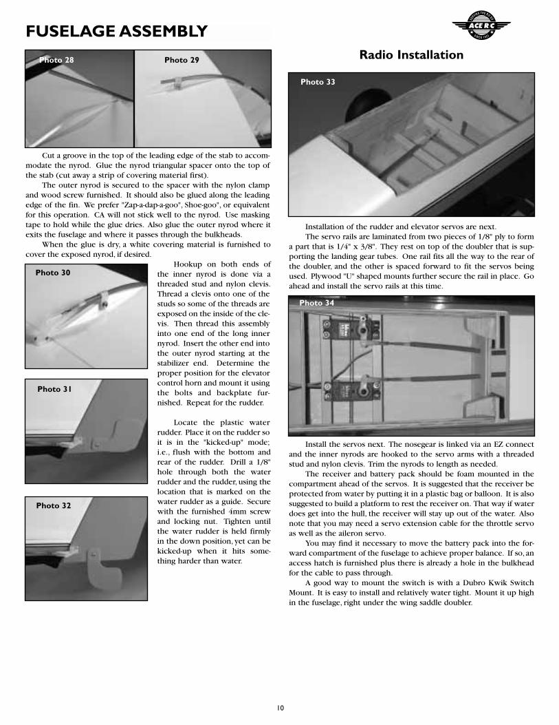
The nosegear is configuredas shown in the above photo.The linkage is a piece of musicwire that goes through an innernyrod that has already beeninstalled in the fuselage. Use a“Z” bend at the steering armend (center hole in the arm).With the music wire linkageinstalled, mount the nosegearbracket to the nose of the planeusing the 3x12mm self tapscrews furnished (drill 1/16”pilot holes.) The bottom of thenose gear bracket should lineup with the bottom of the noseof the plane.
The plastic nose cone isheld in place with the small selftap screws furnished. Drill1/16” pilot holes. You will haveto cut away to clear thenosegear. Obviously, when youfly off of water, the main gearand nosegear will be removed.To remove the nosegear, simplyremove the nose cone, loosenthe collar and steering arm, andthe nosegear will drop out.Take the steering arm off of themusic wire linkage and reinstallthe nose cone.
Hatches
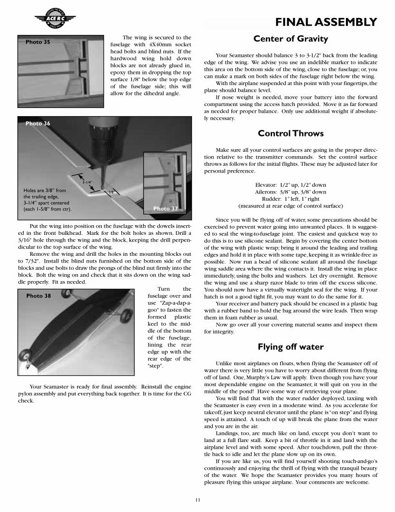
There are two access hatches. One in the front in case you haveto put your batteries in the nose of the plane for proper balance, andone in the rear for installation and maintenance of the rudder and ele-vator linkage.
Cut a diagonal “X” through the covering material that is over bothhatch openings. Use a heat sealing iron to stick the covering down toinside edges and the lips of the openings.
The furnished hatch covers are secured with 4 small self tapscrews; once again drill 1/16” pilot holes. As an alternative, you cansimply cover the joints with clear tape after all assembly and installa-tion is complete and delete the screws.
Photo 13
Photo 16
Photo 17
Photo 15
Photo 14
Photo 18
9
TAIL ASSEMBLYTail Assembly
On the top of the fuse-lage, about 10" from therear, there is a pre-drilledhole for the elevator'souter nyrod to exit. Cutaway the covering materialfrom this hole. By the sametoken, there is a slot in theleft side of the fuselage,about 3" from the rear. Cutaway the covering fromthis slot.
Position the verticalfin on the top rear of thefuselage so it is flush withthe rear and centered onthe fuselage. With a pencil,mark the outline of thebase of the fin on the top ofthe fuselage.
Cut away the coveringfilm from the top of thefuselage about 1/16"INSIDE the mark.
Epoxy the fin onto thefuselage, making sure itremains vertical.
Install the rudder usingthe three furnished hingesin the pre-cut slots. CA thehinges in the same manneras you did for the ailerons.Repeat the process andhinge the elevator to thestabilizer.
Mark the center on the bot-tom of the stabilizer at both theleading edge and trailing edge.
Turn the fuselage over andblock up the wing saddle so thetop of the fin will rest on thebottom of the stabilizer. Makesure the wing saddle remainsparallel with your work surface.The trailing edge of the finshould line up with the trailingedge of the stabilizer (hinge
lines). Making sure the stabilizer is in proper alignment (use your cen-ter marks plus a triangle to make sure it is perpendicular to the fin),
use a pencil to mark where thefin meets the stabilizer. Beingvery careful NOT to cut into thebalsa wood, score and removethe covering material 1/16"inside your marks. Epoxy thestabilizer to the fin, maintainingproper alignment.
Install the two outer nyrods. They will be for the elevator and rud-der linkage. To do so, work from the rear to the front. Start with thelongest one which is for the elevator. Cut off one end at about 45degrees. Thread the angled end through the hole in the top rear of thefuselage, then through the hole in the LEFT side of the rearmost fuse-lage bulkhead. Continue the nyrod forward and thread it through thehole on the LEFT side of the next bulkhead. Leave about 4" of nyrodbehind the leading edge of the stab.
Repeat for the rudder nyrod. It goes through the slot in the sideof the fuselage. It is tricky to hit the large hole that is in the bulkheadbehind the access hatch. Use a piece of .045 or 1/16" music wire firstto "fish" through the hole then follow it with the nyrod. Continue thenyrod on through the holes in the RIGHT side of the next bulkhead.Continue it forward, threading it through the hole in the RIGHT sideof the next bulkhead. Leave about 1" sticking out of the fuselage side.When done, the rudder's nyrod should be on the right side of the fuse-lage so it corresponds to the nosegear linkage.
Reminder: before gluing, make sure the rudder nyrod ends up onthe RIGHT side of the fuselage and corresponds with the nosegearlinkage.
Photo 19
Photo 20
Photo 21
Photo 22
Photo 23
Photo 26
Photo 24
Photo 25
Photo 27
10
FUSELAGE ASSEMBLY
Cut a groove in the top of the leading edge of the stab to accom-modate the nyrod. Glue the nyrod triangular spacer onto the top ofthe stab (cut away a strip of covering material first).
The outer nyrod is secured to the spacer with the nylon clampand wood screw furnished. It should also be glued along the leadingedge of the fin. We prefer "Zap-a-dap-a-goo", Shoe-goo", or equivalentfor this operation. CA will not stick well to the nyrod. Use maskingtape to hold while the glue dries. Also glue the outer nyrod where itexits the fuselage and where it passes through the bulkheads.
When the glue is dry, a white covering material is furnished tocover the exposed nyrod, if desired.
Hookup on both ends ofthe inner nyrod is done via athreaded stud and nylon clevis.Thread a clevis onto one of thestuds so some of the threads areexposed on the inside of the cle-vis. Then thread this assemblyinto one end of the long innernyrod. Insert the other end intothe outer nyrod starting at thestabilizer end. Determine theproper position for the elevatorcontrol horn and mount it usingthe bolts and backplate fur-nished. Repeat for the rudder.
Locate the plastic waterrudder. Place it on the rudder soit is in the "kicked-up" mode;i.e., flush with the bottom andrear of the rudder. Drill a 1/8"hole through both the waterrudder and the rudder, using thelocation that is marked on thewater rudder as a guide. Securewith the furnished 4mm screwand locking nut. Tighten untilthe water rudder is held firmlyin the down position, yet can bekicked-up when it hits some-thing harder than water.
Radio Installation
Installation of the rudder and elevator servos are next.The servo rails are laminated from two pieces of 1/8" ply to form
a part that is 1/4" x 3/8". They rest on top of the doubler that is sup-porting the landing gear tubes. One rail fits all the way to the rear ofthe doubler, and the other is spaced forward to fit the servos beingused. Plywood "U" shaped mounts further secure the rail in place. Goahead and install the servo rails at this time.
Install the servos next. The nosegear is linked via an EZ connectand the inner nyrods are hooked to the servo arms with a threadedstud and nylon clevis. Trim the nyrods to length as needed.
The receiver and battery pack should be foam mounted in thecompartment ahead of the servos. It is suggested that the receiver beprotected from water by putting it in a plastic bag or balloon. It is alsosuggested to build a platform to rest the receiver on. That way if waterdoes get into the hull, the receiver will stay up out of the water. Alsonote that you may need a servo extension cable for the throttle servoas well as the aileron servo.
You may find it necessary to move the battery pack into the for-ward compartment of the fuselage to achieve proper balance. If so, anaccess hatch is furnished plus there is already a hole in the bulkheadfor the cable to pass through.
A good way to mount the switch is with a Dubro Kwik SwitchMount. It is easy to install and relatively water tight. Mount it up highin the fuselage, right under the wing saddle doubler.
Photo 30
Photo 31
Photo 32
Photo 33
Photo 34
Photo 28 Photo 29
11
FINAL ASSEMBLYThe wing is secured to the
fuselage with 4X40mm sockethead bolts and blind nuts. If thehardwood wing hold downblocks are not already glued in,epoxy them in dropping the topsurface 1/8" below the top edgeof the fuselage side; this willallow for the dihedral angle.
Put the wing into position on the fuselage with the dowels insert-ed in the front bulkhead. Mark for the bolt holes as shown. Drill a3/16" hole through the wing and the block, keeping the drill perpen-dicular to the top surface of the wing.
Remove the wing and drill the holes in the mounting blocks outto 7/32". Install the blind nuts furnished on the bottom side of theblocks and use bolts to draw the prongs of the blind nut firmly into theblock. Bolt the wing on and check that it sits down on the wing sad-dle properly. Fit as needed.
Turn thefuselage over anduse "Zap-a-dap-a-goo" to fasten theformed plastickeel to the mid-dle of the bottomof the fuselage,lining the rearedge up with therear edge of the"step".
Your Seamaster is ready for final assembly. Reinstall the enginepylon assembly and put everything back together. It is time for the CGcheck.
Center of Gravity
Your Seamaster should balance 3 to 3-1/2" back from the leadingedge of the wing. We advise you use an indelible marker to indicatethis area on the bottom side of the wing, close to the fuselage; or, youcan make a mark on both sides of the fuselage right below the wing.
With the airplane suspended at this point with your fingertips, theplane should balance level.
If nose weight is needed, move your battery into the forwardcompartment using the access hatch provided. Move it as far forwardas needed for proper balance. Only use additional weight if absolute-ly necessary.
Control Throws
Make sure all your control surfaces are going in the proper direc-tion relative to the transmitter commands. Set the control surfacethrows as follows for the initial flights. These may be adjusted later forpersonal preference.
Elevator: 1/2” up, 1/2” downAilerons: 3/8” up, 3/8” down
Rudder: 1” left, 1” right(measured at rear edge of control surface)
Since you will be flying off of water, some precautions should beexercised to prevent water going into unwanted places. It is suggest-ed to seal the wing-to-fuselage joint. The easiest and quickest way todo this is to use silicone sealant. Begin by covering the center bottomof the wing with plastic wrap; bring it around the leading and trailingedges and hold it in place with some tape,keeping it as wrinkle-free aspossible. Now run a bead of silicone sealant all around the fuselagewing saddle area where the wing contacts it. Install the wing in placeimmediately, using the bolts and washers. Let dry overnight. Removethe wing and use a sharp razor blade to trim off the excess silicone.You should now have a virtually watertight seal for the wing. If yourhatch is not a good tight fit, you may want to do the same for it.
Your receiver and battery pack should be encased in a plastic bagwith a rubber band to hold the bag around the wire leads. Then wrapthem in foam rubber as usual.
Now go over all your covering material seams and inspect themfor integrity.
Flying off water
Unlike most airplanes on floats, when flying the Seamaster off ofwater there is very little you have to worry about different from flyingoff of land. One, Murphy’s Law will apply. Even though you have yourmost dependable engine on the Seamaster, it will quit on you in themiddle of the pond! Have some way of retrieving your plane.
You will find that with the water rudder deployed, taxiing withthe Seamaster is easy even in a moderate wind. As you accelerate fortakeoff, just keep neutral elevator until the plane is “on step”and flyingspeed is attained. A touch of up will break the plane from the waterand you are in the air.
Landings, too, are much like on land, except you don’t want toland at a full flare stall. Keep a bit of throttle in it and land with theairplane level and with some speed. After touchdown, pull the throt-tle back to idle and let the plane slow up on its own.
If you are like us, you will find yourself shooting touch-and-go’scontinuously and enjoying the thrill of flying with the tranquil beautyof the water. We hope the Seamaster provides you many hours ofpleasure flying this unique airplane. Your comments are welcome.
Photo 38
Photo 35
Photo 36
Photo 37
3/8”
3-1/4”
Holes are 3/8” fromthe trailing edge,3-1/4” apart centered(each 1-5/8” from ctr).
12
FLIGHT
PRE-FLIGHT CHECK LIST
❐ 1. Check all control surfaces for possible looseness or deterioration.
❐ 2. Check all screws, clevises, nuts and all other connectors to make sure they are securely fastened.
❐ 3. Check which radio frequencies are being used. Do not turnon your radio until absolutely sure you are the only one oper-ating on that frequency.
❐ 4. Check for proper operation of all control surfaces.
❐ 5. Check the level of charge in both the transmitter and receiverbatteries before flying.
❐ 6. Range check the radio both with and without the engine running!Follow the radio manufacturers instructions for this.
POST-FLIGHT CHECK LIST
❐ 1. Be sure that both the transmitter and receiver switches are turned off.
❐ 2. Drain all excess fuel from the tank. Fuel left in the tank for extended periods can “gunk up”the tank,fittings and carburetor.
❐ 3. Clean the plane with paper towels and a light-duty spray cleanser. Keeping your plane clean will make it last longer and keep it looking nice.
❐ 4. Put a few drops of after-run or light oil in the carburetor andturn the prop over a few times (without the glow plug ignited)to distribute the oil throughout the engine.
❐ 5. Inspect the prop and replace it if any chips or cracks are found.
❐ 6. Inspect the entire plane for covering tears, new dings and dents, loose screws and connectors and any other wear andtear.
SAFETY PRECAUTIONS
1. Wear safety glasses when starting and running all model engines.
2. Model engine fuel is very flammable and the flame is very dangerous because it is almost invisible! Do not smoke or allow sparks, high heat or other flames near the fuel.
3. Do not run model engines inside a garage or other closed room asthey give off large amounts of deadly carbon monoxide gas.
4. Do not run model engines around gravel, sand or other loosedebris. These materials will be ingested through the carburetorand can also be kicked up by the prop.
5. Always stay behind the propeller when the engine is running.Make all engine adjustments from behind the engine.
6. Do not allow loose clothing or other loose objects close to the prop.
7. To stop an engine, cut off the fuel or air supply to the engine.Do not throw rags or other objects into the prop to stop theengine.
8. Do not touch the engine or muffler during or right after it hasbeen running–it gets very hot!