Embed Size (px)
Citation preview

27. Wing to Fu se lage Assembly
Over view
In this section you will be setting the wings’ angle of incidence which, measured at the wing root, isto be +2.5°. The angle of incidence is the angle between the chord line of the wing and the waterlineof the aircraft. When you are flying at cruise speed the fuselage will be level and the wing will beleading edge up 2.5° at the root.
The wing lift pins locate into sockets, which are to be attached to the fuselage sides, and these holdthe wing at the determined angle.
Take care when setting the angle of incidence, especially that both wings are set exactly the same.Any small angular difference between them will result in an aircraft that always wants to roll oneway, requiring a roll trim tab permanently attached to one of the ailerons.
Step 1
Set the fuselage to be level, placing the spirit level on the door recess of the port side (which should be the only place you check the fuselage is level from now on) and ensure that it is secure and stable.You will need room not only for the wings to be installed, and left alone for sufficient time for Reduxto cure, but also for them to be removed, so allow enough room for the spars to come clear of the holes in the fuselage sides. A total of 10.7 m (35 feet) across the wing tips will allow this.
Step 2
Ini tial wing set-up
The following setting up of the wings will need to be temporarily disturbed after this step to allowaccess for local reinforcement plies to be added to the fuselage sides. Set the wings up so the spars are within the fuselage but not quite engaged in the spar sockets.
Dig out the template you last used to set the flaps to the wing, and set it onto the wing root.
The flat top of the template is parallel to the wing root chord so, to be able to set the wing root angle ofincidence to +2.5o, a wedge will be required to allow a spirit level to be used.
To save you doing the calculations, the wedge should be 22.9 cm along one edge for every 1 cm upthe other. The larger you make the wedge the less the error will be so make it as long as practicable.
Support the wings so that the angle of incidence of +2.5o ± 0.05o is set. See figure 1.
Europa Build Man ual Is sue 1 Page 27 - 1

Note that 0.05° equates to a difference in height of only1.1 mm (.044") over a chord of 50". Whensetting the wings ensure that if the bubble in the level is a bit off centre for one wing, then the otherwing should be set to replicate this off centre position. Mark the wing profile onto the fuselage sidefor reference, and also mark the position where the centre of the forward wing pin touches thefuselage. Remove the wings. Drill through the fuselage for the forward wing pin with a 13 mm (½")drill, and subsequently file as necessary.
Step 3
Re in force ment plies
Scuff sand both the inside and outside skins where the lift pin socket hard points are. On the outsideskin, layup 4 plies of ‘bid’ at ± 45° to be a total of 4 cm (1 1/2") longer than the hard points andvertically as large as the wing profile lines marked on the fuselage sides.
On the inside skin, layup also 4 plies of ‘bid’, but extend the layup over the forward hard point downto lap onto the thigh support by 2-3 cm (1"). Run the rear hard point layup onto the forward bulkheadof the baggage bay by 2-3 cm (1"). Cover each layup with peel ply and leave to cure.
Page 27 - 2 Is sue 1 Europa Build Man ual
Fig1. Set ting wing in ci dence.

Step 4
Wing set-up
Wing root pin sock ets
The front socket W27 is rectangular in section, and is shown in figure 2. Each rear socket is anassembly of a W26A, W26B and W26C. The W26A is the main body and is oriented with thesmaller hole between the lugs at the bottom. W26B is the socket housing which slots between thetwo lugs of the body with the double chamfered face innermost. These chamfers allow the housing to rock a limited amount. Holding W26A and W26B together is W26C, the barrel. See figure 3.
Slide the barrel in to the assembly from one side and rotate it so that the large and small holes alignwith the holes in the housing.
The socket assembly should be finally assembled using Loctite 638 to lock the barrel and housingtogether, but allow the barrel to rotate within the lugs of the housing. Make sure that the parts areclean and free from grease before this final assembly. If the barrel does become stiff in the housing,the use of a bar in the socket will enable it to be moved. It does not matter if the assembly remainsstiff though.
Tie-bar fit tings
Supporting the fuselage where the rear socket assemblies will be attached will be a tie-bar assembly,incorporating the fittings W34 and a steel tube W36. Refer to figure 5. In preparation for laterassembly, hold the W26A and W34 fitting together so that their flat circular faces match each other. Drill one of the ¼” holes into the W34 using W26A as a guide. The other two holes will be drilled onassembly in the fuselage. The holes are not pre-drilled in W34 as each assembly may be slightlydifferent.
Europa Build Man ual Is sue 1 Page 27 - 3
Fig 2. W27 front socket. Fig 3. Ex ploded view of W26 wing rear pin socket as sem bly.

Socket at tach ment preparation
Locate the W26 socket assembly onto the wing rear lift pins and secure it using a pip pin BLS4R11N. The pip-pins are sometimes supplied with a second ring attached to the pin’s body. It is best toremove this ring and the lug which it’s attached to. Now push the wings into place and insert the sparbolts through the seat back to locate them. Re-set the wing incidence. Make sure that the spars aretogether and that the port s par is up against the seat back bulkhead.
To check that there is no forward or aft sweep, stretch a string across from wing tip to wing tip, liningit up with the skin joint line of the port wing and a line 32 mm (1¼”) forward of the skin joint line ofthe starboard wing (remember the spars are offset) and sight along it. Alternatively, checkmeasurements between similar points of wing and fuselage on port and starboard sides.
The leading edge sockets W27, which are free to slide on the lift pins, should be able to move a littlebetween the wing root and the fuselage side, whereas there will be a gap between the fuselage sidestep socket shims and the trailing edge sockets.
Measure this gap and, if it is less than 5 mm (3/16"), make a layup on the fuselage side, to reduce thegap to a maximum of 1 mm, from ‘bid’ pieces approximately 1 cm larger than the socket’s rear face.Each ply of ‘bid’ will be approximately 0.25 mm (0.01") thick. Make this pad on a plastic sheet andapply it in one piece.
If the gap between the leading edge or trailing edge sockets and the fuselage side is greater than 5 mm(3/16") up to a maximum of 13 mm (½"), make a shim from good quality plywood to reduce the gapto approximately 2 mm (3/32"). The outer face of the shim should be at least the same size as thesocket and have chamfered edges of 45° to 60°. See figure 4.
The rear sockets, positioned as they are on a part of the fuselage which curves away towards the rear,will require a shim regardless.
Page 27 - 4 Is sue 3 Europa Build Man ual
Fig 4. Ply wood shim as re quired. (Both front and rear shown)

Separate the wings sufficiently far to gain access to the four socket pads. Using Araldite 420 mixedwith flox bond the shims onto the fuselage sides in the relevant places ensuring that the gap ofapproximately 2 mm (3/32") between the socket and shim remains. Either immediately afterwards or after the adhesive has cured, layup 4 plies of ‘bid’ at ± 45° over the shims lapping onto the fuselage atleast 25 mm (1") all around. Cover the entire layups with peel ply.
Step 5
Attaching the sock ets
Scuff sand the rear face of the W26A socket body and remove the peel ply from the fuselagemounting pads. Mix a quantity of Araldite 420 adding flox to stiffen it and apply it to the rear faces ofthe W26A ensuring none gets onto the lift pins.
Reposition the wings with the spar bolts in place and set them up so that the wing incidence is asaccurate as you can achieve.
Orientate the leading edge sockets horizontally and push them inboard to touch the fuselage sides.There is not a great amount of room here but try to remove any excess adhesive that oozes out.
Ensure that the holes in the trailing edge sockets and wing rear pin are aligned by using the pip pins.
Check finally that the fuselage is still secure and level, the wings are not swept forwards or rearwardsand, most importantly, that the angle of incidence of both wings is set at + 2.5o ± 0.05o.
Now walk away and don’t allow anything to be disturbed until the adhesive has cured properly.
After full cure, check again that nothing has moved and that the wings’ incidences have not altered.
Carefully remove the spar bolts and pip pins and slide the wings out of the fuselage, starboard wingfirst.
Step 6
Front sockets
Drill through the 1/4" holes in the front sockets right through the fuselage sides then insert theAN4-10A bolts from inside the fuselage with AN970-4 washers under the heads securing them withMS21042-4 nuts.
Clean up any rough lumps of excess Araldite from around the sockets and fill any gaps that may bepresent with fresh Araldite 420/flox as required. This may be left until you next make up a mix tosave wastage.
Europa Build Man ual Is sue 1 Page 27 - 5
Step 7
Rear sock ets
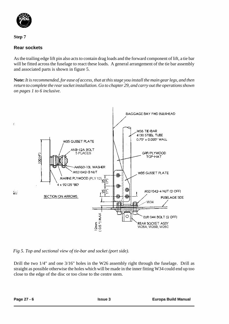
As the trailing edge lift pin also acts to contain drag loads and the forward component of lift, a tie barwill be fitted across the fuselage to react these loads. A general arrangement of the tie bar assemblyand associated parts is shown in figure 5.
Note: It is rec om mended, for ease of ac cess, that at this stage you in stall the main gear legs, and thenre turn to com plete the rear socket in stal la tion. Go to chap ter 29, and carry out the op er a tions shownon pages 1 to 6 in clu sive.
Drill the two 1/4" and one 3/16" holes in the W26 assembly right through the fuselage. Drill asstraight as possible otherwise the holes which will be made in the inner fitting W34 could end up tooclose to the edge of the disc or too close to the centre stem.
Page 27 - 6 Is sue 3 Europa Build Man ual
Fig 5. Top and sec tional view of tie-bar and socket (port side).

Temporarily locate the W34 fitting inside the fuselage using a EUR044 bolt and EUR046 plain nutfor now. With W34 held correctly aligned, drill through the remaining ¼” hole and the 3/16” hole. Install the other EUR044 bolt and EUR046 nut to hold W34 in position.
As the fuselage side is at a slight angle to the aircraft centre line where W34 sits, a shim of epoxy andflox will be required on assembly. Take this into account when positioning W34 at this stage. Mark a line across the top of the centre tunnel (and the ribs in Tri-gear aircraft) in the baggage bay torepresent the )” diameter steel tube tie-bar which will be fitted between the W34 fittings.
It will be seen that it is necessary to cut a slot in the centre tunnel. Cut this slot and adjust its size toleave a clearance around the tube of approximately 3mm (1/8”). Remember that the pitch push-rod is under the tunnel so don’t cut into it by mistake.
Cut slots in the main gear ribs as required, but rather than a narrow slot as in the central tunnel,chamfer the slot sides at a 45º angle where possible. This affords better access for the tie-bar.
Again, temporarily install the W34 fittings, with the tie-bar, and insert the EUR044 bolts in eachside. The thread on the EUR044 bolts should be cut off, but ensure that at least two threads protrudethrough the nut.
Step 8
Gus set Plates
In addition to reacting the tensile/compression loads it is necessary to provide sideways stiffness forasymmetric loads. This is done via two plywood blocks laminated onto the baggage bay frontbulkhead, which are connected to the tie bar by means of a gusset plate, see figure 5.
At the outer 150 mm (6") of the baggage bay front bulkhead mark two horizontal lines showing theposition of the top and bottom of the tie bar.
Make up the two plywood blocks from PLY 12 according to figure 6. As each aircraft is bound to beslightly different, the width of the blocks must be determined by measurement. Round off thecorners to allow for glassfibre to be laid up over the blocks when installed.
Europa Build Man ual Is sue 3 Page 27 - 7
Fig 6. Ply wood block for gus set plates.

Step 9
Scuff sand the bulkhead where the plywood blocks fit and the surrounding 5 cm (2”). Using rapidepoxy spread over the entire bonding face, bond the plywood block on to the bulkhead, as faroutboard as possible, but allowing space for the shortened EUR044 bolt and aligning it with thetie-bar. Remember to allow 2.5 mm (0.1”) between the block and the tie-bar for the thickness ofglass fibre which will go over the block.
Once secure, remove the tie-bar and W34 fittings and layup four plies of ‘bid’ at ± 45º over theplywood block, lapping onto the bulkhead all around as shown in figure 8. Make fillets with flox inthe corners first to prevent the formation of air bubbles. Cover with peel ply and allow to cure.
After cure, remove the peel ply and reposition the tie-bar assembly. Position a W35 gusset plate ontop of the plywood block and tie-bar and, using the two holes as a guide, drill right through the tie-barcentre-line with a 4.8 mm drill. Install an AN3-12A bolt in each hole after drilling to ensurealignment for the next hole.
Now mark a line on the upper gusset plates which is central to the plywood block, then mark thecentres for three holes, each 25 mm (1”) apart and 13 mm (!”) from the edge of the plate. Drill rightthrough with a 4.8 mm drill.
Next, install a W35 and W35A gusset plate to each end of the tie-bar, one above and one below,bolting them to the tie-bar with AN3-12A bolts, AN960-10L washer and MS21042-3 nuts. Drillthrough the lower gusset plate with the last 3 holes and install AN3-12A bolts in these also. Don’tadd the nuts to these bolts yet as you’re just about to remove the assembly yet again. (The lowergusset plates W35A are undrilled to allow for drill alignment variations).
Step 10
Fi nal as sem bly of tie-bar
Init ially remove all componentsidentifying where they were fitted forre-assembly. Clean away any burrs andswarf caused by drilling. At this stage itwould be a good idea to paint the tie-barto protect it against corrosion so that it’sdry ready for final assembly.
Prepare each side of the slot in the central tunnel of the cockpit module for a glassfibre layup by removing the upper skinand foam to expose about 10 mm (*”) ofthe lower skin. See sectional diagram infigure 7.
Page 27 - 8 Is sue 1 Europa Build Man ual
Fig 7. Sec tion through bag gage bay cen tre tun nel.

The tie-bar can now be installed for the last time. For the final installation of the tie-bar assemblymake a stiff mix of flox and spread this on the flat face of the W34 fittings to form a shim to take upthe uneven gap between them and the fuselage sides. With the tie-bar in place, fit the assembly intothe fuselage and install the EUR044 bolts and MS21042-4 nuts and the EUR045 bolts (suitablyshortened similar to the EUR044 bolts) and MS21042-3 nuts.
Do not fully tighten the bolts at this point just tighten them enough to prevent movement of the W34fittings. Scrape away any excess flox from around the W34s.
Install the gusset plates with the AN3-12A bolts, AN960-10L washers and MS21042-3 nuts.
Step 11
Cen tral tun nel slot clo sure
The final task to be done is to close the slot in the tunnel, tying the tie-bar into it in the process. Cutpieces of 3 mm foam to fit into the slot across the top and down the angled sides. The side pieces may be in two pieces each to take it around the tie-bar. Scuff sand the bonding areas each side of the slot.
Layup
Layup 2 plies of ‘bid’ at ± 45º on plastic sheeting at least 30 cm x 20 cm (12” x 8”). Cut a strip to fitinto the slot and lay it to join the inner skins together. Drape it over the tie-bar, cutting it to allow it togo around the tie-bar at the sides. See figure 8.
Apply a layer of flox to the underside of the 3 mm foam pieces and lay them in place over the firstlayup.
Europa Build Man ual Is sue 1 Page 27 - 9
Fig 8. Sec tion through tun nel de tail ing layup se quence.

Next, coat the upper portion of foam with flox and finally layup 2 plies of ‘bid’ at ± 45º over the foamlapping onto the surrounding glass fibre and the tie-bar by about 20 mm ()”).
You may actually find it easier to lay the glass cloth onto both sides of the foam before installing itrather than in the stages as described above.
Cover with peel ply and allow to cure.
Step 12
Front stiff ener
Extra stiffness of the fuselage skin behind the forward lift socket is achieved by the addition of a75 mm (3") wide stiffener laid up on the inside. See figure 9
Page 27 - 10 Is sue 1 Europa Build Man ual
Fig 9. Par tial view on in side cock pit wall (star board side).

Using scraps of blue styrofoam, make two pieces to the dimensions 410 mm x 75 mm x 7 mm thick(161
4“ x 3" x 14” thick).
To make the foam 7 mm (14“) thick, cut it slightly thicker then, with 7 mm thick wooden battens
nailed to a flat surface wide enough apart to fit the foam, sand across the foam until you contact thebattens. The thickness of the foam is not super-critical.
Trim the foam to fit vertically between the seat thigh support and the underside of the door aperture,when central relative to the forward lift pin socket.
Chamfer off the vertical edges to allow transition of the glassfibre layup which will go over the foamand dig out cavities in the foam to allow the bolt heads holding the socket to fit.
Cut a total of 6 pieces of ‘bid’ ± 45o 130 mm (5") wide x 475 mm (19") long.
Scuff sand the inside skin, top of the thigh support and underside of the door aperture flange.
Flox the foam cores in place on the fuselage side and, ensuring it is against the side wall, allow tocure.
Next, coat the exposed foam with micro slurry and layup 3 plies of ‘bid’ at ± 45o over each foampiece, lapping onto the fuselage all around by about 25 mm (1").Cover the edges, at least, with peel-ply and allow to cure.
After cure, remove the peel-ply and carefully drill through the socket’s hole, right through thefuselage side, with a 12 mm drill to allow the pin to penetrate.
Europa Build Man ual Is sue 1 Page 27 - 11

Spar pins
There are two different spar pins; one being a pip-pin the other a plain steel pin. The pip-pin is to beused on the port side of the aircraft to retain the tip end of the starboard wing spar in the event of anoverload. The rigging socket is not regarded as a structural component. The tip end of the port spar is restrained by the starboard spar behind it.
Step 13
Pip-pin
The pip-pin supplied is deliberately slightly too long which enables fine adjustment of its fit in eachindividual aircraft. To be effective, the pip-pin balls should be no further than 0.020” (0.5 mm) fromthe rear of the rigging socket.
To strengthen the rigging socket hole against which the pip-pin will react, a hardened steel washer isto be bonded in place. A sectional view through the spar at the pip-pin location is shown in figure 10.
Page 27 - 12 Is sue 4 Europa Build Man ual
Fig 10. Sec tion through port side spar pin bush area.

Set the port wing on supports with the trailing edge uppermost. Scuff sand the rear face of the rigging socket, which is bonded to the port wing spar, in preparation for bonding. Scuff sand also thehardened washer both sides. You will bond the washer to the rigging socket then retain it with a plyof ‘bid’.
Prepare a piece of ‘bid’ about 50 mm x 50 mm (2” x 2”) and mix up a small quantity of epoxy (approx50 g). Keeping enough epoxy to wet out the ‘bid’, mix a small quantity of flox into the rest to make awettish consistency. Apply the flox to the concave side of the slightly conical washer and thenposition it over the hole of the rigging socket. Use one of the !” bolts to centre the washer then, withflox added around the outer edge of the washer to make a fillet, apply the single ply of ‘bid’ whichwill retain it. Although the ‘bid’ covers the hole, it is best to leave it now and clear it out after cure toavoid disturbing it.
It would be a good precaution to apply a thin layer of grease to the bore of the bush to avoid any epoxy drips sticking.
After cure, cut open the hole through the ‘bid’ and sand away the glass fibre within 2 - 3 mm (&”) ofthe hole to ensure that the pip-pin balls contact the washer when installed rather than the glass fibre.
Step 14
Pip-pin length ad just ment
Rig the wings into the fuselage and install the pip-pin in the port side seat back bush. The pip-pin’sbutton needs to be depressed until the pin is fully in. Check that the button springs out after insertion. If it doesn’t, there is something preventing the balls from emerging.
Without pressing the button in, pull on the pin until the balls contact the hardened washer. Measurethe gap between the underside of the pin’s head and the seat back. This gap should be taken up with a spacer which is between 0.1 and 0.5 mm (0.004” and 0.020”) less than that measured.
To make up the spacer, select a number of the AN960-816L washers, which are approximately 0.8mm (0.032”) thick each and include one slightly conical hard steel washer over them which addsanother 2 mm (0.080”). Refer to figure 10. Slide the calculated combination onto the pip-pin andassemble the wings. Check that the pin’s button pops out, so engaging the balls and that the free playis less than 0.5 mm (0.020”).
Position the washer assembly in place with a greased !” bolt and pot around them with a mix of rapidepoxy with flox to make a fairly stiff mix. The idea is only to retain the washers when the aircraft isderigged. To make the washer assembly more secure add a couple of plies of ‘bid’, lapping 10 - 20mm (*” - )”) onto the seat back. Do this after removal of the bolt and ensure that no glass fibre is leftbetween the washer and the pin head, otherwise the pin length adjustment will be affected.
Europa Build Man ual Is sue 1 Page 27 - 13

Step 15
Star board spar pin
The starboard spar pin SO7 will require the threaded end cutting off so that it measures 85mm
(3-3/8”) from under the head. Round off the end to enable easy location. A sectional view throughthe spar at the starboard pin location is shown in figure 11.
Step 16
Star board Spar pin latch
After inserting the two spar pins duringrigging, the starboard pin handle is to besecured in a simple receptacle mounted in thecorner of the fuselage side and seat back. As afurther safety consideration, a latch preventsthe pin handle from swinging out of thereceptacle making it impossible to come out ofthe spars. See figure 12.
Page 27 - 14 Is sue 4 Europa Build Man ual
Fig 11. Sec tion through star board side spar pin area.
Fig 12. Spar pin in and latched in safety receptacle

The receptacle is made from 12 mm plywood, part number PLY-5. See figure 13.
The slot should be positioned by holding the receptacle in place as indicated in figure 13 and marking where the pin handle contacts it. Drill a 13 mm (½") hole for the end of the slot, centred 10 mm (3/8”) from the edge and cut the remaining piece away to make the slot.
Trim the total length of the receptacle to be no more than 13 mm (12“) forward of the slot to minimise
intruding into occupant space.
Latch
The latch -part number S09 - is shown infigure 14.
Hold the latch in place on the edge of thereceptacle with the slot in it and drill two 3 mm (1
8“) holes for the latch pivot and catch.Screw the latch to the receptacle, using EUR 024 screws, the forward screw, with an AN960-10Lwasher under its head, acting as the pivot to minimise possible inadvertent operation by the seat backcushion.
Europa Build Man ual Is sue 4 Page 27 - 15
Fig 13. Di men sions and po si tion of pin re cep ta cle.
Fig 14. Safety Latch - S09

In stal la tion
Remove the latch and screws for final installation.
Scuff sand the fuselage side and seat back where the receptacle will go then, using rapid epoxy mixed with flox, bond the receptacle in place.
Next, layup 2 plies of bid at ± 45o over the top and bottom of the receptacle, lapping onto the fuselageand seat back 20-25 mm (3
4“-1"). Cover with peel ply and allow to cure before reinstalling the latch.
Step 17
Pin iden ti fi ca tion
Although the safety latch should act as a reminder, it is possible to rig the aircraft and put the spar pins in the incorrect locations so it is important to identify the pins and the holes in the seat back in somemanner. For example, paint the handle end of the port side pip-pin red, the starboard pin green andpaint a matching colour around the holes. Alternatively, attach the pip-pin to a strap which is secured to the fuselage, via the seat belt attachment bolt for example, to avoid it being used on the starboardside.
Step 18
Ai le ron quick con nect bellcrank pivot po si tion re po si tion ing
The important thing with the aileron quick-connect system is that the pivots of both W16 and CS15bellcranks are properly aligned. Having set them up initially in the cockpit module you may find thatthey no longer align properly when the fuselage is assembled. First, visually check the pivot boltsalignment with the wings rigged. Note the amount and direction of misalignment. You will need tomove the bolt in the spar.
Remove both W16 and CS15 bellcranks from their pivot bolts. Remove the bolt in the spar byheating it carefully to soften the Flox, then tap it out with a hammer. File a slot for the pivot bolt andits head to allow the bolt to align with the pivot bolt of CS15.
Find a piece of rigid tube which fits onto the 1/4" diameter pivot bolts, and is the same length as theCS15 pivot bolt. Slide the tube onto the CS15 pivot bolt. Install the W16 bolt through the spar withFlox, making sure it is not on the thread. Apply tape over the back of the Flox filled hole to prevent itbeing pushed out.
Rig the wings then, gaining access from under the wing and using long nosed pliers, slide the tubewhich is on CS15’s pivot bolt so that it is half on both bolts- be careful not to push the W16 pivot boltback into the spar. Leave to cure.
Page 27 - 16 Is sue 1 Europa Build Man ual

Remember to slide the tube over the pivot bolts back before attempting to derig the wings. Now referback to the aileron quick connect section and re-install the bellcranks.
Step 19
Ai le ron quick con nect bellcrank pads
Rig the wings to the fuselage again; you’ll notice that there is a gap between the pairs ofquick-connect bellcrank faces. Insert temporary shims into the gaps to make them parallel thenmeasure the gap.
Make a pad for each wing from the piece of 1 mm thick Tufnol (EUR 008) to fit into the gaps with aminimum of 0.25 mm (0.010") clearance to allow for the thickness of Araldite 420 adhesive. Sandthe Tufnol to obtain the thickness desired, and scuff sand the outboard faces of the CS15P and CS15S bellcranks.
Separate the wings enough to give access to the bellcranks, then bond the pads in place using Araldite 420 adhesive. Making absolutely sure that there is no adhesive on the front of the pad, put the wingsback on to ensure that the gap between the bellcranks is completely filled, and the pad is not too thick. Wipe away any adhesive that oozes out and leave to cure.
Re-rig the aircraft and operate the aileron controls to check for any lost motion, and for any stiffnessin operation, particularly if the stiffness increases with aileron deflection.
Step 20
Ai le ron quick con nect bellcrank
At full aileron deflection (roll to starboard) there is the possibility that a corner of the aileron quickconnect bellcrank CS15P, which is mounted in the fuselage, may contact the spar pip-pin. With theaircraft rigged and the aileron controls correctly adjusted, the W16P bellcrank will not contact thepin. See figure 15 and confirm this on the aircraft.
Europa Build Man ual Is sue 1 Page 27 - 17
Fig 15. De tail of port side ai le ron quick con nect bellcrank.

To avoid contact with the pin, the cornerof CS15P should be removed as shown infigure 16. Ensure that the inner corner isradiused as shown.
On installation, check that there isclearance between the spar pin andCS15P, making any small adjustment asnecessary.
Step 21Spar guides
Although not an essential addition, spar guides attached to the aileron quick connect bellcrankmounting bracket make wing rigging easier. Using Tufnol allows the spar to slide easily into thefuselage and not damage the layup on the flange of CS14. Forming the guide as an “L” shapeprevents the spar from sliding aft. See figure 17.
Page 27 - 18 Is sue 1 Europa Build Man ual
Fig 17. Lo ca tion of spar guide - star board shown.
Fig 16. Cut-out as re quired in CS15P.

Spar strap
When the wings become loaded in flight, the spars within the fuselage bend, as well as the wingsthemselves. Due to the spar pins being supported by the seat back bulkhead only, the spars try totwist as well as bend.
To limit the twisting effect, a 75 mm (3”) wide glass fibre strap is to be attached to the port wing sparat the aircraft centre-line. The strap is to be laid up directly around the starboard spar, which will besuitably treated with release tape, to ensure a perfect fit.
Preparation
Step 22
Star board spar
To accommodate spar bending, the strap needs to be made with some clearance at each end over thespar’s upper edge. Without this, the starboard spar would tend to shear the strap from the port spar asit bends. To form this clearance, cut a piece of thin card to the width of the spar and at least 90 mm(3/1/2”) long and cover it with release tape.
Using two 3 mm thick spacers placed on the spar as shown in figure 18, position the card formerbetween them so that it curves and, using the release tape, attach it to the spar. Wrap the release tape,all around the spar trying not to distort the curved shape of the card. It might be wise to support thecard in various places underneath so you don’t lose the curve.
Europa Build Man ual Is sue 1 Page 27 - 19
Fig 18. For mer po si tion on spar.

Step 23
Port spar
Scuff sand the central 15 cm (6”) all around the port wing spar in readiness for bonding the strap to it. Support the port wing, leading edge down and arrange it such that the starboard wing can be rigging in position with it, but don’t put them together at this stage.
Layup
Cover an area of your work bench with plastic sheeting, then directly onto it make two differentlayups. One will be the strap, the other will form two brackets.
! Brackets - Layup 2 plies of ‘bid’ at ± 45º large enough to cut two 90 mm x 90 mm (3” x 3”)squares.
! Strap - Layup a strip large enough to cut a piece 350 mm x 90 mm (14” x 3”) to the followingschedule.
2 x ‘bid’ at ± 45º .2 x ‘uni’ (fibres running lengthwise).2 x ‘bid’ at ± 45º .
Position the bracket layups onto the centre of the port spar, lapping just 25 mm (1”) onto the sparsrear face, one at the upper edge, the other at the lower edge. See figure 19. For now, leave thebracket’s pieces hanging down.
Page 27 - 20 Is sue 1 Europa Build Man ual
Fig 19. Bracket plies in po si tion on port spar.

Now position the starboard spar onto the portspar and insert the spar pins or two ½” boltsthrough the spar bushes. Ensure that the sparsare properly together, use clamps if necessarybut don’t squeeze the centres of the sparstogether.
With the spars together, wrap the bracketlayups around the starboard spar. See figure20.
Apply flox to make a fillet between thebracket layups and the port spar then lay on the strap layup, over the brackets wrappingaround onto the forward face of the port spar. The strap is not meant to overlap here, so trim the ends if necessary. Having made sure that the layupsare properly in place, leave to cure.
After cure, remove the spar pins and separate the spars. Trim the edges of the strap to remove sharpedges, adjusting the strap’s width to no less than 75 mm (3”).See figure 21.
Note: It may be necessary to separate the spars with a scissor jack, but be careful not to apply anyimpact load.
Finally remove the release tape and cardformer from the starboard spar.
Wing root fairings
The gap between the wing root and thefuselage skin will be filled with themoulded fairing. The fairing becomes partof the wing which further adds to the wingroot stiffness and can assist in passingforward and aft wing loads into thefuselage.
Step 24
With the wings properly rigged applylayers of tape or a piece of card to thefuselage sides, where the root fairing will
be, to a thickness of about 2 mm. Lay the fairing onto the wing so that it touches the 2mm spacer youhave just made. Mark the fuselage sides to indicate the pip pin positions as they will become hiddenby the fairings. Mark the position of the fairing on the wing.
Europa Build Man ual Is sue 2 Page 27 - 21
Fig 20. Brackets wrapped around star board spar.
Fig 21. Spar strap trimmed to size.

Scuff sand the area of contact and then bond the fairing to the wing with Araldite 420/flox, beingcareful to keep the adhesive clear of the fuselage sides. Leave to cure.
Step 25
After cure, cut a hole through the fairing to extract the pip pins and remove the wings. This holeshould be as small as possible to avoid reducing the strength and stiffness of the root rib.
With the wings rigged, any gap between the fuselage and wing fairing should be sealed by applyingsilicone to the fairing having applied a sheet of thin plastic to act as a release agent to the fuselage side first. Leave the wings rigged until the silicone has set. Note: Do this after painting otherwise areas that have been in contact with the silicone will not allow paint to adhere.
Ai le ron set ting up pro ce dure
Ini tial set-up
1. Check that the short aileron link-rod is adjusted such that when the bellcrank W13 is against itsstop, the aileron has moved 23.5º up.
2. With the aileron at neutral, adjust the length of the lateral push-rod so that the quick-connectbellcrank W16 is at 90º to a line between both spar bushes.
3. Adjust the tie-rod between both cranks CS08 so that both control columns are parallel.
4. Adjust the short outer push-rods between the CS08’s and the CS15 bellcranks so that the latter arevertical when the control columns are vertical.
When the wings are rigged the aileron movement should be 23.5º up and 20º down with full lateralcontrol column movement and both ailerons should be in their neutral positions together when thecontrol columns are vertical.
Ad just ments
If more than 20º down aileron is achieved, shorten the aileron link rod. This will, of course, increasethe upward movement of that particular aileron, so check that the aileron stop in the opposite wingprevents the mass balance weights from contacting the wing skin.
If both ailerons are slightly up instead of being in their neutral positions when the control columns are vertical, shorten the two outer push-rods linking CS08 to CS15. Lengthen these push-rods if theailerons are slightly down together.
Pitot/static tube
Drill two 1/4” diameter holes through the port fuselage side midway between the forward wingsocket and the spar opening, making sure to keep them away from the seat belt mounting. Theseholes are for the pitot/static tubes.
When rigging the aircraft the tubes will be led over the top of the spar tang
Page 27 - 22 Is sue 2 Europa Build Man ual