Embed Size (px)
Citation preview

Geotechnical Reports
1. West Rapid Substation GT Exploration and Review2. West Rapid City Substation Investigative Borings3. West Rapid Substation Transmission Line Poles GT Report
SDPUC 1.10c

CONSULTANTS • GEOTECHNICAL• MATERIALS• ENVIRONMENTAL• FORENSICS
www.amengtest.com
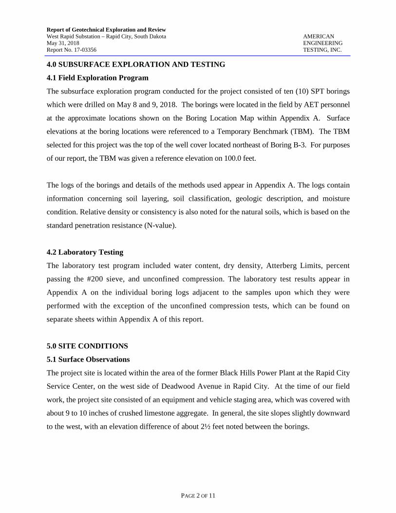
REPORT OF GEOTECHNICAL EXPLORATION AND REVIEW
WEST RAPID SUBSTATION RAPID CITY SERVICE CENTER 409 DEADWOOD AVENUE RAPID CITY, SOUTH DAKOTA
AET No. 17-03356
Date: May 31, 2018
Prepared for:
Black Hills Energy 7001 Mt. Rushmore Road Rapid City, South Dakota 57702

1745 Samco Road | Rapid City, SD 57702 Phone (605) 388-0029 | Toll Free (800) 972-6364 | Fax (605) 388-0064 | www.amengtest.com | AA/EEO
This document shall not be reproduced, except in full, without written approval from American Engineering Testing, Inc.
May 31, 2018 Black Hills Energy 7001 Mt. Rushmore Road Rapid City, South Dakota 57702 Attn: Mr. Ron Williams, PE RE: Geotechnical Exploration and Review West Rapid Substation Rapid City Service Center 409 Deadwood Avenue Rapid City, South Dakota Report No.17-03356 Dear Ron, American Engineering Testing, Inc. (AET) is pleased to present the results of our subsurface exploration program and geotechnical engineering review for the proposed West Rapid Substation to be constructed at 409 Deadwood Avenue, in Rapid City, South Dakota. These services were performed in general accordance with our proposal dated April 10, 2018 and the signed Statement of Services No. 38863, dated April 25, 2018. We are submitting one (1) electronic copy of the report to you and one (1) additional copy to Ms. Maria Garduna (Black Hills Energy). Within the limitations of scope, budget, and schedule, our services have been conducted according to generally accepted geotechnical engineering practices at this time and location. Other than this, no warranty, either expressed or implied, is intended. Important information regarding risk management and proper use of this report is given in the Appendix entitled “Geotechnical Report Limitations and Guidelines for Use”. Please contact our office if you have any questions about the report. We can also be contacted to arrange the observation and testing services during construction of the project. Sincerely, American Engineering Testing, Inc. Walt Feeger, P.E. Senior Geotechnical Engineer Phone: (605) 388-0029 [email protected]
Page i
CONSULTANTS · GEOTECHNICAL · MATERIALS · ENVIRONMENTAL
A AMERICANENGINEERINGTESTING, INC.

Report of Geotechnical Exploration and Review West Rapid Substation – Rapid City, South Dakota AMERICAN May 31, 2018 ENGINEERING Report No. 17-03356 TESTING, INC.
Page ii Copyright 2018 American Engineering Testing, Inc. All Rights Reserved
Unauthorized use or copying of this document is strictly prohibited by anyone other than the client for the specific project.
SIGNATURE PAGE
Prepared for: Prepared by: Black Hills Energy American Engineering Testing, Inc. 7001 Mt. Rushmore Road 1745 Samco Road Rapid City, South Dakota 57701 Rapid City, South Dakota 57702 Attn: Mr. Ron Williams, PE Report Authored By: Peer Review Conducted By: Walt Feeger, P.E. Robert Temme, P.E. Senior Geotechnical Engineer Vice President – Western Region

Report of Geotechnical Exploration and Review West Rapid Substation – Rapid City, South Dakota AMERICAN May 31, 2018 ENGINEERING Report No. 17-03356 TESTING, INC.
TABLE OF CONTENTS Transmittal Letter ........................................................................................................................................... i Signature Page .............................................................................................................................................. ii TABLE OF CONTENTS ............................................................................................................................. iii 1.0 INTRODUCTION .................................................................................................................... 1 2.0 SCOPE OF SERVICES ............................................................................................................ 1 3.0 PROJECT INFORMATION ..................................................................................................... 1 4.0 SUBSURFACE EXPLORATION AND TESTING ................................................................ 2
4.1 Field Exploration Program .................................................................................................... 2 4.2 Laboratory Testing ................................................................................................................ 2
5.0 SITE CONDITIONS ................................................................................................................. 2 5.1 Surface Observations ............................................................................................................. 2 5.2 Subsurface Soils/Geology ....................................................................................................... 3 5.3 Groundwater .......................................................................................................................... 3 5.3 Hydrocarbon Impacted Soils and Groundwater .................................................................... 3
6.0 RECOMMENDATIONS .......................................................................................................... 4 6.1 Discussion .............................................................................................................................. 4 6.2 General Site Preparation Recommendations ......................................................................... 5 6.3 Drilled Pier Foundation Recommendations .......................................................................... 6 6.4 Spread Footing or Mat Foundation Recommendations ......................................................... 8 6.5 Backfill Considerations ......................................................................................................... 9
7.0 CONSTRUCTION CONSIDERATIONS .............................................................................. 10 7.1 Potential Difficulties ............................................................................................................ 10 7.2 Runoff Water in Excavation ................................................................................................ 10 7.3 Disturbance of Soils............................................................................................................. 10 7.4 Excavation Backsloping ...................................................................................................... 11 7.5 Observation and Testing ...................................................................................................... 11
8.0 LIMITATIONS ....................................................................................................................... 11 APPENDIX A - Geotechnical Field Exploration and Testing Boring Log Notes Unified Soil Classification System Site Location Map Boring Location Map Subsurface Boring Logs Unconfined Compression Test Results APPENDIX B - Geotechnical Report Limitations and Guidelines for Use
Page iii

Report of Geotechnical Exploration and Review West Rapid Substation – Rapid City, South Dakota AMERICAN May 31, 2018 ENGINEERING Report No. 17-03356 TESTING, INC.
PAGE 1 OF 11
1.0 INTRODUCTION
We understand the construction of a new substation has been proposed at Black Hills Energy’s
Rapid City Service Center facility at 409 Deadwood Avenue in Rapid City, South Dakota. Please
refer to the Site Location Map included in Appendix A of this report. To assist with the planning
and design, American Engineering Testing, Inc. (AET) has been authorized to conduct a
subsurface exploration program at the site, conduct soil laboratory testing, and perform a
geotechnical engineering review for the project. This report presents the results of the above
services, and provides our engineering recommendations based on this data.
2.0 SCOPE OF SERVICES
AET's services were performed in general accordance with our proposal dated April 10, 2018. The
authorized scope consists of the following:
• Ten (10) standard penetration test (SPT) borings within the proposed substation area to depths of about 30 feet below existing grade.
• Soil laboratory testing. • Geotechnical engineering analysis based on the gained data and preparation of this
report. These services are intended for geotechnical purposes only. The scope is not intended to explore
for the presence or extent of environmental contamination.
3.0 PROJECT INFORMATION
Based on the information provided, we understand the proposed 230/69kV substation will be
constructed at Black Hills Energy’s Rapid City Service Center facility located at 409 Deadwood
Avenue in Rapid City. The substation will consist of a control building as well as deadends,
bus/switch supports, transformers, and take-off structures. Furthermore, we understand these types
of structures are typically placed on pad/mat foundations or reinforced concrete drilled piers
(caissons).
The previously stated information represents our understanding of the proposed construction. This
information is an integral part of our engineering review. It is important that you contact us if there
are changes from that described so that we can evaluate whether modifications to our
recommendations are appropriate.
Report of Geotechnical Exploration and Review West Rapid Substation – Rapid City, South Dakota AMERICAN May 31, 2018 ENGINEERING Report No. 17-03356 TESTING, INC.
PAGE 2 OF 11
4.0 SUBSURFACE EXPLORATION AND TESTING
4.1 Field Exploration Program
The subsurface exploration program conducted for the project consisted of ten (10) SPT borings
which were drilled on May 8 and 9, 2018. The borings were located in the field by AET personnel
at the approximate locations shown on the Boring Location Map within Appendix A. Surface
elevations at the boring locations were referenced to a Temporary Benchmark (TBM). The TBM
selected for this project was the top of the well cover located northeast of Boring B-3. For purposes
of our report, the TBM was given a reference elevation on 100.0 feet.
The logs of the borings and details of the methods used appear in Appendix A. The logs contain
information concerning soil layering, soil classification, geologic description, and moisture
condition. Relative density or consistency is also noted for the natural soils, which is based on the
standard penetration resistance (N-value).
4.2 Laboratory Testing
The laboratory test program included water content, dry density, Atterberg Limits, percent
passing the #200 sieve, and unconfined compression. The laboratory test results appear in
Appendix A on the individual boring logs adjacent to the samples upon which they were
performed with the exception of the unconfined compression tests, which can be found on
separate sheets within Appendix A of this report.
5.0 SITE CONDITIONS
5.1 Surface Observations
The project site is located within the area of the former Black Hills Power Plant at the Rapid City
Service Center, on the west side of Deadwood Avenue in Rapid City. At the time of our field
work, the project site consisted of an equipment and vehicle staging area, which was covered with
about 9 to 10 inches of crushed limestone aggregate. In general, the site slopes slightly downward
to the west, with an elevation difference of about 2½ feet noted between the borings.

Report of Geotechnical Exploration and Review West Rapid Substation – Rapid City, South Dakota AMERICAN May 31, 2018 ENGINEERING Report No. 17-03356 TESTING, INC.
PAGE 3 OF 11
5.2 Subsurface Soils/Geology
Underlying approximately 9 to 10 inches of aggregate surfacing, the subsurface soils encountered
in the borings consisted of about 1 to 12 feet of fill overlying varying depths of alluvium and/or
claystone bedrock and gypsum, associated with the Spearfish Formation. The fill is comprised of
residual coal from the former power plant as well as silty/sandy lean clays. The alluvium consists
of stiff to hard lean clays. The claystone/gypsum bedrock extended to the total depths explored in
each of the borings, with the exception of Boring B-1. Within Boring B-1, the alluvial silty lean
clays extended to the total depth explored.
Conditions encountered at each boring location are indicated on the individual boring logs in
Appendix A of this report.
5.3 Groundwater
At the time of our field work, measurable groundwater was encountered within Borings B-1, B-2, B-
4, B-7, and B-10 at depth varying from approximately 10½ to 15 feet below existing grades. The
presence or lack of groundwater noted at the boring locations should not be taken as an accurate
representation of the actual groundwater levels. Groundwater level fluctuations occur due to seasonal
variations in the amount of precipitation, surface drainage, local irrigation practices, and other factors
not evident at the time the borings were performed. Due to the relatively low permeability of the
clay soils encountered in the borings, a relatively long period of time may be needed for a groundwater
level to develop and/or stabilize in the borings. The possibility of encountering groundwater and
associated fluctuations in groundwater levels should be considered when developing the design and
construction plans for the project.
5.3 Hydrocarbon Impacted Soils and Groundwater
Potential hydrocarbon impacted soils and groundwater may be encountered during the project
excavation activities based on field photoionization detector (PID) screening results of samples
obtained from the borings (please refer to the results shown on the Boring Logs). Hydrocarbon
impacted soils that are encountered during the excavation activities could be considered solid
waste material by the South Dakota Department of Environment and Natural Resources (SD
DENR), which would require proper removal and disposal in accordance with SD DENR
guidelines.
Report of Geotechnical Exploration and Review West Rapid Substation – Rapid City, South Dakota AMERICAN May 31, 2018 ENGINEERING Report No. 17-03356 TESTING, INC.
PAGE 4 OF 11
Regarding hydrocarbon-impacted groundwater that may require dewatering during the project,
concentrations of hydrocarbons in groundwater may exceed the surface water quality standards as
established by the SD DENR, and therefore, cannot be discharged as surface water. If dewatering
of hydrocarbon impacted groundwater is required for the project, the successful bidding contractor
for the project would need to coordinate with the City of Rapid City to obtain permission to
discharge to the sanitary sewer or discuss other potential disposal options acceptable to the City of
Rapid City and/or DENR.
6.0 RECOMMENDATIONS
6.1 Discussion
Our recommendations in the following sections are based on our understanding of the project
details at this time. The geotechnical engineer should be allowed to review the final project plans
to verify the following recommendations remain applicable for construction.
Based on the field and laboratory data, it is our opinion drilled pier foundations can be used to
support the proposed dead-end structures, transmission line poles, and other miscellaneous
substation structures. Conventional spread footing or mat foundations can be used for support of
the new control building, transformers, capacitor banks, or other miscellaneous support equipment
provided the recommendations provided herein are followed.
As designed, spread footing/mat loadings should provide a theoretical safety factor of 3 or more
with respect to a general shear or base failure of the footings/mats. For drilled piers, loadings
should provide a theoretical safety factor of 2 or more. Total and differential movement should not
exceed 1-inch and 1/2-inch, respectively.
Additionally, it should be noted that gypsum is a common geologic feature found in the Spearfish
Formation derived soils at this site. Once exposed, gypsum material can degrade which could
cause future movement related distress to the structures, especially if water is introduced to the
gypsum matrix.

Report of Geotechnical Exploration and Review West Rapid Substation – Rapid City, South Dakota AMERICAN May 31, 2018 ENGINEERING Report No. 17-03356 TESTING, INC.
PAGE 5 OF 11
If gypsum is encountered at the base of the excavations for foundations, retaining walls, and
concrete slabs-on-grade, the geotechnical engineer should be allowed to observe the excavations
and provide additional recommendations. Such recommendations typically involve over-
excavation of the gypsum material to a specified depth and replacement with approved engineered
fill material or lean concrete flowable fill. Gypsum fragments greater than 2-inches in nominal
size should be screened out of all fill material prior to placement. Drilled pier foundations should
not terminate (end bear) on gypsum.
6.2 General Site Preparation Recommendations
At this time, a grading plan or design finished structure elevations has not been provided. Based
on the elevations obtained at the boring locations, fills on the order of about 3 feet (or less) will be
required along the western portion of the proposed substation in order to provide a level building
pad. All proposed imported fill material required to reach the design substation grade elevations
should consist of lean clay or sand/gravel material. We do not recommend fat clay or shale
material be used as fill within the proposed substation. All proposed imported material should be
submitted to the geotechnical engineer for approval prior to being hauled and stockpiled on-site.
The existing aggregate surfacing, coal layers associated with the former power plant, and other
unsuitable materials should be removed from within the construction limits of the proposed new
substation. Any former infrastructure or structural elements associated with the former power
plant should also be removed in their entirely if encountered during require site excavations. The
existing lean clay material may be left in-place provided it is properly reconditioned as
recommended herein prior to placement of structures and/or additional fill material required
Once the required stripping and foundation excavations are complete, we recommend the exposed
subgrade soils be moisture conditioned to within ±3% of the optimum moisture content and
compacted to at least 92% of maximum modified Proctor dry density (ASTM D 1557). Once
completed and approved, applicable engineered fill zones and/or structural elements may be
placed.

Report of Geotechnical Exploration and Review West Rapid Substation – Rapid City, South Dakota AMERICAN May 31, 2018 ENGINEERING Report No. 17-03356 TESTING, INC.
PAGE 6 OF 11
6.3 Drilled Pier Foundation Recommendations
Based on the results of the borings, laboratory testing, and our analysis, we have developed the
following design parameters. We recommend all drilled piers bear at least 5 feet into the very
stiff/hard lean clay alluvium or claystone bedrock and have a minimum length of 15 feet.
Soil Type Allowable Skin Friction (psf)
Allowable End Bearing Pressure (psf)
Frost Zone 0 – 5’
Ignore Ignore
Lean Clay Fill 300 na
Lean Clay Alluvium 600 6,000
Gypsum na na
Claystone Bedrock 1,000 10,000
In designing to resist uplift, ⅔ of the allowable side friction values provided for compressive
loading could be used along with the effective weight of the drilled shafts. Straight shaft piers
with a minimum diameter of 18-inches are recommended. Proper reinforcing steel should be
included in the drilled shaft designs.
Lateral deflections of drilled shafts should be evaluated using an appropriate design procedure, and
would be dependent on shaft diameter, length, configuration, stiffness and “fixed head” or “free
head” conditions.
Single pier lateral load capacity can be estimated using the following design parameters for the soil
profile in a p-y analysis such as conducted using the computer program LPILE:
Design Parameter Lean Clay Fill Lean Clay Alluvium Gypsum Claystone
Moist Unit Weight (pcf) 115 120 na 125
Undrained Shear Strength (psf) 1,000 2,000 na 4,000
Friction Angle (degrees) 18 18 na 15
Static Soil Modulus Parameter, k (pci) 500 500 na 2,000
Strain, ε50 (in/in) 0.005 0.005 na 0.004
Report of Geotechnical Exploration and Review West Rapid Substation – Rapid City, South Dakota AMERICAN May 31, 2018 ENGINEERING Report No. 17-03356 TESTING, INC.
PAGE 7 OF 11
Drilling to design depths should be possible with conventional large drilled pier equipment.
Difficult drilling should be anticipated where gypsum masses are encountered which may require
rock cutting teeth and/or coring in order to advance the drilled pier hole. We highly recommend a
separate bid item be provided in the bid documents that addresses drilling through the gypsum.
Care should be taken so that the sides and bottom of the shaft excavations are not disturbed during
drilling. The bottom of the shaft excavations should be free of loose material and water when
concrete is placed. Concrete should be placed as soon as possible after the foundation excavation is
completed to reduce the potential for disturbance of the bearing surface.
Groundwater was encountered at the time of our field work; therefore, the use of temporary casing
will likely be required. The need for casing will depend on the conditions encountered at the time
the pier excavations are made. A sufficient head of plastic concrete having a minimum slump on the
order of 6-8 inches should be maintained inside the casing as it is withdrawn to prevent concrete
arching and the influx of soil and water (if encountered) and creation of voids in the pier shaft.
Drilled shaft construction should be constructed in accordance with applicable portions of ACI
336.3R-93 or other similar, approved specification. Concrete mix should be designed utilizing
cement to have a minimum 28-day compressive strength of 4,000 psi and a maximum water cement
ratio of 0.45. A super plasticizer may be necessary to increase concrete slump/flow temporarily for
drilled shaft placement.
Concrete should be on-site and ready for placement as soon as practical after each pier excavation is
completed. Concrete placement in pier excavations should occur on the same day as pier excavation
is completed.
We do not recommend free-fall concrete placement in piers. The use of a bottom-dump hopper,
tremie, or pump, discharging near the bottom of the hole where concrete segregation will be
minimized, is recommended.

Report of Geotechnical Exploration and Review West Rapid Substation – Rapid City, South Dakota AMERICAN May 31, 2018 ENGINEERING Report No. 17-03356 TESTING, INC.
PAGE 8 OF 11
A representative from AET should observe all drilled shaft excavations to evaluate the suitability of
the bearing materials and to verify that conditions in the drilled shaft excavations are consistent with
those encountered in the test borings. If unsuitable materials are encountered at planned depths, it
may be necessary to deepen the shaft.
6.4 Spread Footing or Mat Foundation Recommendations
As noted, clay soils are present at the site. In order to limit potentially damaging differential and total
movements through moisture variations in the clay soils, we recommend the site clays be removed
within the proposed structure footprints to allow for the placement of at least two (2) feet of imported
granular low/non-frost susceptible engineered fill below the foundations and/or mats.
Where applicable, excavations should be laterally oversized at a 1H:1V ratio as necessary to
accommodate the two (2) feet of granular engineered fill material. Once the over excavation is
complete, we recommend the exposed subgrade be scarified to a depth of at least 8-inches, the
moisture content of the scarified soils adjusted to ±3% of the optimum moisture content and the
scarified soils compacted to at least 92% of maximum modified Proctor dry density (ASTM D
1557). The excavated site clays may be stockpiled on-site and used as overlot fill outside of the
building limits, where required.
Conventional Spread Footing Foundations – Imported granular engineered fill can then be placed
within the over-excavations below the foundations. The granular engineered fill should be pre-
approved by the geotechnical engineer prior to use. The granular engineered fill should be a pit
run or crushed/screened material with a maximum aggregate size of 3-inches, no more than 15%
passing the #200 sieve with a Liquid Limit less than 25. Engineered fill should be placed in 8-
inch thick maximum loose lifts; the moisture content conditioned to within ±3% of optimum
moisture content and compacted to at least 95% of maximum modified Proctor (ASTM D 1557)
dry density.
We recommend exterior footings, interior footings in unheated portions of the building, or footings
placed during freezing conditions be placed at least four (4) feet below final grades for frost
protection. Interior footings in heated areas may be placed directly below the floor slab (where
applicable).
Report of Geotechnical Exploration and Review West Rapid Substation – Rapid City, South Dakota AMERICAN May 31, 2018 ENGINEERING Report No. 17-03356 TESTING, INC.
PAGE 9 OF 11
The spread footing foundation system may be designed for an allowable bearing capacity of 2,500
pounds per square foot (psf) bearing on the properly placed imported granular engineered fill. As
designed, loadings should provide a theoretical safety factor of three or more with respect to a
general shear or base failure of the footings. Total and differential settlement should not exceed 1
inch and 1/2-inch, respectively.
Mat Foundations – In our opinion, the proposed substation structures can also be supported by a
slab-on-grade (mat) foundation system bearing on a zone of compacted select (low frost
susceptible) granular engineered fill extending to a depth of at least two (2) feet below the base of
the mat. The mat foundation system may be designed for an allowable bearing capacity of 2,500
pounds per square foot (psf). As designed, loadings should provide a theoretical safety factor of
three or more with respect to a general shear or base failure of the footings. Total and differential
settlement should not exceed 1 inch and 1/2-inch, respectively.
Lateral loads transmitted to the mat foundation can be resisted by the soil-concrete friction on the
base of the foundation. The friction on the base of the concrete and underlying granular engineered
fill may be computed using a friction coefficient of 0.45.
6.5 Backfill Considerations
It is our opinion exterior backfill around the structures, utility trench backfill and overlot fill may
consist of the site soils and should be placed as follows. All recommendations are based on the
modified Proctor method (ASTM: D 1557).
1. All backfill should be free of deleterious/frozen material and have a maximum aggregate
size of 3-inches. Gypsum material, if encountered, should be removed to the extent possible and in no case should fill material contain gypsum fragments greater than 2-inches in nominal size.
2. Fill should be moisture conditioned to within ±3% of optimum moisture content prior to
being placed.
3. All fill should be placed in loose lift thicknesses of 8-inches or less. If hand-operated compaction equipment is used, the loose lift thickness should be reduced to 4-inches or less.

Report of Geotechnical Exploration and Review West Rapid Substation – Rapid City, South Dakota AMERICAN May 31, 2018 ENGINEERING Report No. 17-03356 TESTING, INC.
PAGE 10 OF 11
4. Each lift of backfill should be compacted to at least 92% of maximum proctor density. Compaction should be increased to 95% for the final lift of utility trench backfill placed within areas to receive pavement.
5. Compaction density tests should be performed on alternating lifts to ensure the minimum
density is maintained.
7.0 CONSTRUCTION CONSIDERATIONS
7.1 Potential Difficulties
Depending on the time of year in which construction takes place, unstable subgrade soils could be
encountered during the site and building grading operations. If encountered, additional
conditioning of the soils may be required to obtain moisture contents which allow for firm and
unyielding subgrade and/or compaction.
Localized areas of soft wet subgrades can be remedied with additional excavation to expose firmer
soils, placement of coarse rock to provide a solid base on which to place additional fill and/or the
use of geotextiles between the soft soils and the overlying fill and/or pavement sections. The
appropriate means of subgrade stabilization should be evaluated by the geotechnical engineer at
the time of construction.
7.2 Runoff Water in Excavation
Water can be expected to collect in the excavation bottom during times of inclement weather or
snow melt. To allow observation of the excavation bottom, reduce the potential for soil
disturbance, and facilitate filling operations, we recommend water be removed from within the
excavation during construction. Based on the soils encountered, we anticipate the groundwater can
be handled with conventional sump pumping.
7.3 Disturbance of Soils
The on-site soils can become disturbed under construction traffic, especially if the soils are wet.
If soils become disturbed, they should be subcut to the underlying undisturbed soils. The subcut
soils can then be dried and recompacted back into place, or they should be removed and replaced
with drier imported fill.

Report of Geotechnical Exploration and Review West Rapid Substation – Rapid City, South Dakota AMERICAN May 31, 2018 ENGINEERING Report No. 17-03356 TESTING, INC.
PAGE 11 OF 11
7.4 Excavation Backsloping
If excavation faces are not retained, the excavations should maintain maximum allowable slopes in
accordance with OSHA Regulations (Standards 29 CFR), Part 1926, Subpart P, “Excavations” (can
be found on www.osha.gov). Even with the required OSHA sloping, water seepage or surface runoff
can potentially induce sideslope erosion or running which could require slope maintenance.
7.5 Observation and Testing
The recommendations in this report are based on the subsurface conditions found at our test boring
locations. Since the soil conditions can be expected to vary away from the soil boring locations,
we recommend on-site observation by a geotechnical engineer/technician during construction to
evaluate these potential changes. Soil density testing should also be performed on new fill placed
in order to document that project specifications for compaction have been satisfied.
8.0 LIMITATIONS
Within the limitations of scope, budget, and schedule, our services have been conducted according
to generally accepted geotechnical engineering practices at this time and location. Other than this,
no warranty, either expressed or implied, is intended. Important information regarding risk
management and proper use of this report is given in Appendix B entitled “Geotechnical Report
Limitations and Guidelines for Use”.

Report of Geotechnical Exploration and Review West Rapid Substation – Rapid City, South Dakota AMERICAN May 31, 2018 ENGINEERING Report No. 17-03356 TESTING, INC.
Appendix A AET Project No. 17-03356
Boring Log Notes
Unified Soil Classification System Site Location Map
Boring Location Map Subsurface Boring Logs
Unconfined Compression Test Results

Report of Geotechnical Exploration and Review West Rapid Substation – Rapid City, South Dakota AMERICAN May 31, 2018 ENGINEERING Report No. 17-03356 TESTING, INC.
A.1 FIELD EXPLORATION The subsurface conditions at the site were explored by drilling and sampling standard penetration test borings. The locations of the borings appear on the Boring Location Map, preceding the Subsurface Boring Logs in this appendix. A.2 SAMPLING METHODS A.2.1 Ring-lined barrel Samples - Calibrated to N60 Values Standard penetration (ring-lined barrel) samples were collected in general accordance with ASTM: D3550. The ASTM test method consists of driving a 2.5-inch O.D. thick-walled, split-barrel sampler lined with brass rings into the in-situ soil with a 140-pound hammer dropped from a height of 30 inches. The sampler is driven a total of 18 inches into the soil. After an initial set of 6 inches, the number of hammer blows to drive the sampler the final 12 inches is known as the standard penetration resistance or N-value. A.2.2 Disturbed Samples (DS)/Spin-up Samples (SU) Sample types described as “DS” or “SU” on the boring logs are disturbed samples, which are taken from the flights of the auger. Because the auger disturbs the samples, possible soil layering and contact depths should be considered approximate. A.2.3 Sampling Limitations Unless actually observed in a sample, contacts between soil layers are estimated based on the spacing of samples and the action of drilling tools. Cobbles, boulders, and other large objects generally cannot be recovered from test borings, and they may be present in the ground even if they are not noted on the boring logs. Determining the thickness of “topsoil” layers is usually limited, due to variations in topsoil definition, sample recovery, and other factors. Visual-manual description often relies on color for determination, and transitioning changes can account for significant variation in thickness judgment. Accordingly, the topsoil thickness presented on the logs should not be the sole basis for calculating topsoil stripping depths and volumes. If more accurate information is needed relating to thickness and topsoil quality definition, alternate methods of sample retrieval and testing should be employed. A.3 CLASSIFICATION METHODS Soil descriptions shown on the boring logs are based on the Unified Soil Classification (USC) system. The USC system is described in ASTM: D2487 and D2488. Where laboratory classification tests (sieve analysis or Atterberg Limits) have been performed, accurate classifications per ASTM: D2487 are possible. Otherwise, soil descriptions shown on the boring logs are visual-manual judgments. Charts are attached which provide information on the USC system, the descriptive terminology, and the symbols used on the boring logs. Visual-manual judgment of the AASHTO Soil Group is also noted as a part of the soil description. A chart presenting details of the AASHTO Soil Classification System is also attached. The boring logs include descriptions of apparent geology. The geologic depositional origin of each soil layer is interpreted primarily by observation of the soil samples, which can be limited. Observations of the surrounding topography, vegetation, and development can sometimes aid this judgment. A.4 WATER LEVEL MEASUREMENTS The ground water level measurements are shown at the bottom of the boring logs. The following information appears under “Water Level Measurements” on the logs:
Date and Time of measurement Sampled Depth: lowest depth of soil sampling at the time of measurement Casing Depth: depth to bottom of casing or hollow-stem auger at time of measurement Cave-in Depth: depth at which measuring tape stops in the borehole Water Level: depth in the borehole where free water is encountered Drilling Fluid Level: same as Water Level, except that the liquid in the borehole is drilling fluid
Report of Geotechnical Exploration and Review West Rapid Substation – Rapid City, South Dakota AMERICAN May 31, 2018 ENGINEERING Report No. 17-03356 TESTING, INC.
The true location of the water table at the boring locations may be different than the water levels measured in the boreholes. This is possible because there are several factors that can affect the water level measurements in the borehole. Some of these factors include: permeability of each soil layer in profile, presence of perched water, amount of time between water level readings, presence of drilling fluid, weather conditions, and use of borehole casing. A.5 LABORATORY TEST METHODS A.5.1 Water Content Tests Conducted per AET Procedure 01-LAB-010, which is performed in general accordance with ASTM: D2216 and AASHTO: T265. A.5.2 Atterberg Limits Tests Conducted per AET Procedure 01-LAB-030, which is performed in general accordance with ASTM: D4318 and AASHTO: T89, T90. A.5.3 Sieve Analysis of Soils (thru #200 Sieve) Conducted per AET Procedure 01-LAB-040, which is performed in general conformance with ASTM: D6913, Method A. A.6 TEST STANDARD LIMITATIONS Field and laboratory testing is done in general conformance with the described procedures. Compliance with any other standards referenced within the specified standard is neither inferred nor implied. A.7 SAMPLE STORAGE Unless notified to do otherwise, we routinely retain representative samples of the soils recovered from the borings for a period of 30 days.

UNIFIED SOIL CLASSIFICATION SYSTEM ASTM Designations: D 2487, D2488
AMERICAN ENGINEERING TESTING, INC.
Criteria for Assigning Group Symbols and Group Names Using Laboratory TestsA
Soil Classification Notes ABased on the material passing the 3-in (75-mm) sieve. BIf field sample contained cobbles or boulders, or both, add “with cobbles or boulders, or both” to group name. CGravels with 5 to 12% fines require dual symbols: GW-GM well-graded gravel with silt GW-GC well-graded gravel with clay GP-GM poorly graded gravel with silt GP-GC poorly graded gravel with clay DSands with 5 to 12% fines require dual symbols: SW-SM well-graded sand with silt SW-SC well-graded sand with clay SP-SM poorly graded sand with silt SP-SC poorly graded sand with clay (D30)2
ECu = D60 /D10, Cc = D10 x D60 FIf soil contains >15% sand, add “with sand” to group name. GIf fines classify as CL-ML, use dual symbol GC-GM, or SC-SM. HIf fines are organic, add “with organic fines” to group name. IIf soil contains >15% gravel, add “with gravel” to group name. JIf Atterberg limits plot is hatched area, soils is a CL-ML silty clay. KIf soil contains 15 to 29% plus No. 200 add “with sand” or “with gravel”, whichever is predominant. LIf soil contains >30% plus No. 200, predominantly sand, add “sandy” to group name. MIf soil contains >30% plus No. 200, predominantly gravel, add “gravelly” to group name. NPl>4 and plots on or above “A” line. OPl<4 or plots below “A” line. PPl plots on or above “A” line. QPl plots below “A” line. RFiber Content description shown below.
Group Symbol
Group NameB
Coarse-Grained Soils More than 50% retained on No. 200 sieve
Gravels More than 50% coarse fraction retained on No. 4 sieve
Clean Gravels Less than 5% finesC
Cu>4 and 1<Cc<3E GW Well graded gravelF
Cu<4 and/or 1>Cc>3E GP Poorly graded gravelF
Gravels with Fines more than 12% fines C
Fines classify as ML or MH GM Silty gravelF.G.H
Fines classify as CL or CH GC Clayey gravelF.G.H
Sands 50% or more of coarse fraction passes No. 4 sieve
Clean Sands Less than 5% finesD
Cu>6 and 1<Cc<3E SW Well-graded sandI
Cu<6 and 1>Cc>3E SP Poorly-graded sandI
Sands with Fines more than 12% fines D
Fines classify as ML or MH SM Silty sandG.H.I
Fines classify as CL or CH SC Clayey sandG.H.I
Fine-Grained Soils 50% or more passes the No. 200 sieve (see Plasticity Chart below)
Silts and Clays Liquid limit less than 50
inorganic PI>7 and plots on or above “A” lineJ
CL Lean clayK.L.M
PI<4 or plots below “A” lineJ
ML SiltK.L.M
organic Liquid limit–oven dried <0.75
Liquid limit – not dried OL Organic clayK.L.M.N
Organic siltK.L.M.O
Silts and Clays Liquid limit 50 or more
inorganic PI plots on or above “A” line CH Fat clayK.L.M
PI plots below “A” line MH Elastic siltK.L.M
organic Liquid limit–oven dried <0.75
Liquid limit – not dried OH Organic clayK.L.M.P
Organic siltK.L.M.Q
Highly organic soil
Primarily organic matter, dark in color, and organic in odor
PT PeatR
3 2 ½ 1 ¾ 4 10 20 40 60 140 200100
80
60
40
20
0
0
20
40
60
80
100
81Sieve NumberScreen Opening (in.)
50 10 5 1.0 0.10.5
PARTICLE SIZE IN MILLIMETERS
SIEVE ANALYSIS
PERC
ENT
PAS
SING
PERC
ENT
RET
AINE
D
D60 = 15mm
D30 = 2.5mm
D10 = 0.075mm
Cu = = = 200D60D10
150.075 Cc = = = 5.6(D30)
D10 x D602.5
0.075 x 152 2
CL-ML
For classification of fine-grained soils and fine-grained fraction of coarse-grained soils.
Equation of "A"-lineHorizontal at PI = 4 to LL = 25.5. then PI = 0.73 (LL-20)
Equation of "U"-lineVertical at LL = 16 to PI = 7. then PI = 0.9 (LL-8)
"A" LINE
"U" LINE
CL OR OL
CH OR OH
10 20 30 40 50 60 70 80 90 100 110 0 0
10
20
30
40
50
60
16
7 4
PLAS
TICI
TY IN
DEX
(PI)
LIQUID LIMIT (LL) Plasticity Chart
ADDITIONAL TERMINOLOGY NOTES USED BY AET FOR SOIL IDENTIFICATION AND DESCRIPTION
Grain Size Term Particle Size Boulders Over 12" Cobbles 3" to 12" Gravel #4 sieve to 3" Sand #200 to #4 sieve Fines (silt & clay) Pass #200 sieve
Gravel Percentages Term Percent A Little Gravel 3% - 14% With Gravel 15% - 29% Gravelly 30% - 50%
Consistency of Plastic Soils Term N-Value, BPF Very Soft less than 2 Soft 2 - 4 Firm 5 - 8 Stiff 9 - 15 Very Stiff 16 - 30 Hard Greater than 30
Relative Density of Non-Plastic Soils Term N-Value, BPF
Very Loose 0 - 4 Loose 5 - 10 Medium Dense 11 - 30 Dense 31 - 50
Very Dense Greater than 50
Moisture/Frost Condition (MC Column)
D (Dry): Absence of moisture, dusty, dry to touch. M (Moist): Damp, although free water not visible. Soil may still have a high water content (over “optimum”). W (Wet/ Free water visible intended to Waterbearing): describe non-plastic soils. Waterbearing usually relates to sands and sand with silt. F (Frozen): Soil frozen
Layering Notes Laminations: Layers less than ½" thick of differing material or color. Lenses: Pockets or layers greater than ½" thick of differing material or color.
Fiber Content of Peat Fiber Content Term (Visual Estimate) Fibric Peat: Greater than 67% Hemic Peat: 33 – 67% Sapric Peat: Less than 33%
Organic/Roots Description (if no lab tests) Soils are described as organic, if soil is not peat and is judged to have sufficient organic fines content to influence the soil properties. Slightly organic used for borderline cases. With roots: Judged to have sufficient quantity of roots to influence the soil properties. Trace roots: Small roots present, but not judged to be in sufficient quantity to significantly affect soil properties.


20
14
18
13
18
25
31
45
25
ND
ND
ND
ND
ND
ND
ND
ND
NSR
LIMESTONE AGGREGATE SURFACING,9 inchesFILL, Silty Lean Clay with Sand, reddishbrown (CL)
SILTY LEAN CLAY with SAND, reddishbrown, very stiff to hard, sandstone fragmentspresent (CL)
Bottom of Boring
43 1996
110
114
SURFACINGFILL
ALLUVIUM
18
18
18
18
18
18
18
18
18
M
M
M
M
W
M
M
M
M
MC
MC
MC
MC
MC
MC
MC
MC
MC
26
19
20
BORINGCOMPLETED: 5/8/18
CAVE-INDEPTH
5/8/18 12.5
CASINGDEPTH
LG:
31.5
DEPTH:
DRILLINGFLUID LEVELDATE
NA3.25" HSA
SURFACE ELEVATION:
RC-1
DRILLING METHOD NOTE: REFER TO
THE ATTACHED
SHEETS FOR AN
EXPLANATION OF
TERMINOLOGY ON
THIS LOGES
NA
SAMPLEDDEPTH30.0
WATER LEVEL MEASUREMENTS
TIME
DR:
30.0
92.6
JH
WATERLEVEL
10:20
Rig:
FIELD & LABORATORY TESTSMC
DEN
1
2
3
4
5
6
7
8
9
10
11
12
13
14
15
16
17
18
19
20
21
22
23
24
25
26
27
28
29
30
31
DEPTHIN
FEET WC PLLL PID(ppm)
N RECIN.
03/2011 01-DHR-060
17-03356
AMERICANENGINEERINGTESTING, INC.
SUBSURFACE BORING LOG
SAMPLETYPE
GEOLOGY
West Rapid Substation; Rapid City, South Dakota
MATERIAL DESCRIPTION
AET JOB NO:
PROJECT:
B- 1 (p. 1 of 1)LOG OF BORING NO.
AE
T_C
OR
P
17-0
3356
.GP
J A
ET
+C
PT
+W
ELL
.GD
T
5/30
/18

38
50/.3
34
20
50/.4
NSR
50/.4
50/.4
50/.4
ND
ND
ND
ND
ND
ND
ND
ND
NSR
LIMESTONE AGGREGATE SURFACING,10 inchesFILL, Silty Lean Clay Sand, reddish brown(CL)
GYPSUM, white, hard
CLAYSTONE, Silty Lean Clay, red, very stiffto hard, gypsum lenses present (CL)
Bottom of Boring
SURFACING
FILL
SPEARFISHFORMATION
18
10
18
18
17
0
11
11
11
M
M
M
M
W
M
M
M
M
MC
MC
MC
MC
MC
MC
MC
MC
MC
8
13
BORINGCOMPLETED: 5/8/18
CAVE-INDEPTH
5/8/18 13.0
CASINGDEPTH
LG:
30.9
DEPTH:
DRILLINGFLUID LEVELDATE
NA3.25" HSA
SURFACE ELEVATION:
RC-1
DRILLING METHOD NOTE: REFER TO
THE ATTACHED
SHEETS FOR AN
EXPLANATION OF
TERMINOLOGY ON
THIS LOGES
NA
SAMPLEDDEPTH30.0
WATER LEVEL MEASUREMENTS
TIME
DR:
30.0
94.0
JH
WATERLEVEL
17:00
Rig:
FIELD & LABORATORY TESTSMC
DEN
1
2
3
4
5
6
7
8
9
10
11
12
13
14
15
16
17
18
19
20
21
22
23
24
25
26
27
28
29
30
DEPTHIN
FEET WC PLLL PID(ppm)
N RECIN.
03/2011 01-DHR-060
17-03356
AMERICANENGINEERINGTESTING, INC.
SUBSURFACE BORING LOG
SAMPLETYPE
GEOLOGY
West Rapid Substation; Rapid City, South Dakota
MATERIAL DESCRIPTION
AET JOB NO:
PROJECT:
B- 2 (p. 1 of 1)LOG OF BORING NO.
AE
T_C
OR
P
17-0
3356
.GP
J A
ET
+C
PT
+W
ELL
.GD
T
5/30
/18
50/.5
50/.5
50/.5
50/.5
50/.3
NSR
78/.8
50/.2
50/.3
ND
ND
ND
ND
ND
ND
ND
ND
NSR
LIMESTONE AGGREGATE SURFACING,9 inchesFILL, Coal, black
GYPSUM, white, hard, siltstone lenses present
CLAYSTONE, Silty Lean Clay, red, hard,gypsum lenses present (CL)
Bottom of Boring
SURFACINGFILL
SPEARFISHFORMATION
12
12
6
6
4
0
16
9
10
M
M
M
M
M
M
M
M
M
MC
MC
MC
MC
MC
MC
MC
MC
MC
BORINGCOMPLETED: 5/9/18
CAVE-INDEPTH
5/9/18 None
CASINGDEPTH
LG:
30.8
DEPTH:
DRILLINGFLUID LEVELDATE
NA3.25" HSA
SURFACE ELEVATION:
RC-1
DRILLING METHOD NOTE: REFER TO
THE ATTACHED
SHEETS FOR AN
EXPLANATION OF
TERMINOLOGY ON
THIS LOGES
NA
SAMPLEDDEPTH30.0
WATER LEVEL MEASUREMENTS
TIME
DR:
30.0
95.2
JH
WATERLEVEL
8:30
Rig:
FIELD & LABORATORY TESTSMC
DEN
1
2
3
4
5
6
7
8
9
10
11
12
13
14
15
16
17
18
19
20
21
22
23
24
25
26
27
28
29
30
DEPTHIN
FEET WC PLLL PID(ppm)
N RECIN.
03/2011 01-DHR-060
17-03356
AMERICANENGINEERINGTESTING, INC.
SUBSURFACE BORING LOG
SAMPLETYPE
GEOLOGY
West Rapid Substation; Rapid City, South Dakota
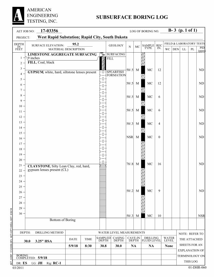
MATERIAL DESCRIPTION
AET JOB NO:
PROJECT:
B- 3 (p. 1 of 1)LOG OF BORING NO.
AE
T_C
OR
P
17-0
3356
.GP
J A
ET
+C
PT
+W
ELL
.GD
T
5/30
/18

45
55
50/.5
85/.8
90
75/.9
50
NSR
50/.3
ND
ND
ND
15
55
<1
ND
<1
NSR
LIMESTONE AGGREGATE SURFACING,10 inchesFILL, Silty Lean Clay with Sand, reddishbrown (CL)
CLAYSTONE, Silty Lean Clay, red, hard(CL)
with gypsum lenses
Sampler Refusal at 30.3'
119
SURFACING
FILL
SPEARFISHFORMATION
18
18
12
16
18
17
18
0
4
M
M
M
M
W
M
M
M
M
MC
MC
MC
MC
MC
MC
MC
MC
MC
8
7
9
11
BORINGCOMPLETED: 5/9/18
CAVE-INDEPTH
5/9/18 12.0
CASINGDEPTH
LG:
30.3
DEPTH:
DRILLINGFLUID LEVELDATE
NA3.25" HSA
SURFACE ELEVATION:
RC-1
DRILLING METHOD NOTE: REFER TO
THE ATTACHED
SHEETS FOR AN
EXPLANATION OF
TERMINOLOGY ON
THIS LOGES
NA
SAMPLEDDEPTH30.0
WATER LEVEL MEASUREMENTS
TIME
DR:
30.0
93.5
JH
WATERLEVEL
9:50
Rig:
FIELD & LABORATORY TESTSMC
DEN
1
2
3
4
5
6
7
8
9
10
11
12
13
14
15
16
17
18
19
20
21
22
23
24
25
26
27
28
29
30
DEPTHIN
FEET WC PLLL PID(ppm)
N RECIN.
03/2011 01-DHR-060
17-03356
AMERICANENGINEERINGTESTING, INC.
SUBSURFACE BORING LOG
SAMPLETYPE
GEOLOGY
West Rapid Substation; Rapid City, South Dakota
MATERIAL DESCRIPTION
AET JOB NO:
PROJECT:
B- 4 (p. 1 of 1)LOG OF BORING NO.
AE
T_C
OR
P
17-0
3356
.GP
J A
ET
+C
PT
+W
ELL
.GD
T
5/30
/18

42
35
35
46
17
78
50/.2
NSR
NSR
ND
ND
179
146
82
ND
ND
ND
NSR
LIMESTONE AGGREGATE SURFACING,10 inchesFILL, Coal, blackSILTY LEAN CLAY with SAND, reddishbrown, very stiff to hard, claystone fragmentspresent (CL)
with gypsum fragments
CLAYSTONE, Silty Lean Clay, red, hard,gypsum lenses present (CL)
Sampler Refusal at 30.0'
99
112
126
SURFACIING
FILL
ALLUVIUM
SPEARFISHFORMATION
18
18
18
18
18
18
9
0
0
M
M
M
M
M
M
M
M
M
MC
MC
MC
MC
MC
MC
MC
MC
MC
26
19
18
9
BORINGCOMPLETED: 5/9/18
CAVE-INDEPTH
5/9/18 None
CASINGDEPTH
LG:
30.0
DEPTH:
DRILLINGFLUID LEVELDATE
NA3.25" HSA
SURFACE ELEVATION:
RC-1
DRILLING METHOD NOTE: REFER TO
THE ATTACHED
SHEETS FOR AN
EXPLANATION OF
TERMINOLOGY ON
THIS LOGES
NA
SAMPLEDDEPTH30.0
WATER LEVEL MEASUREMENTS
TIME
DR:
30.0
95.0
JH
WATERLEVEL
12:00
Rig:
FIELD & LABORATORY TESTSMC
DEN
1
2
3
4
5
6
7
8
9
10
11
12
13
14
15
16
17
18
19
20
21
22
23
24
25
26
27
28
29
30
DEPTHIN
FEET WC PLLL PID(ppm)
N RECIN.
03/2011 01-DHR-060
17-03356
AMERICANENGINEERINGTESTING, INC.
SUBSURFACE BORING LOG
SAMPLETYPE
GEOLOGY
West Rapid Substation; Rapid City, South Dakota
MATERIAL DESCRIPTION
AET JOB NO:
PROJECT:
B- 5 (p. 1 of 1)LOG OF BORING NO.
AE
T_C
OR
P
17-0
3356
.GP
J A
ET
+C
PT
+W
ELL
.GD
T
5/30
/18

55
50/.5
40
66
50/.5
50/.4
50/.4
NSR
50/.3
105
173
164
33
13
<1
ND
<1
NSR
LIMESTONE AGGREGATE SURFACING,10 inchesFILL, Coal, black
SILTY LEAN CLAY with SAND, reddishbrown, hard, claystone and gypsum fragmentspresent (CL)
CLAYSTONE, Silty Lean Clay with Sand,red, hard, gypsum lenses present (CL)
Bottom of Boring
119
115
SURFACING
FILL
ALLUVIUM
SPEARFISHFORMATION
18
12
18
18
6
11
11
0
10
M
M
M
M
M
M
M
M
M
MC
MC
MC
MC
MC
MC
MC
MC
MC
12
12
11
9
BORINGCOMPLETED: 5/9/18
CAVE-INDEPTH
5/9/18 None
CASINGDEPTH
LG:
30.8
DEPTH:
DRILLINGFLUID LEVELDATE
NA3.25" HSA
SURFACE ELEVATION:
RC-1
DRILLING METHOD NOTE: REFER TO
THE ATTACHED
SHEETS FOR AN
EXPLANATION OF
TERMINOLOGY ON
THIS LOGES
NA
SAMPLEDDEPTH30.0
WATER LEVEL MEASUREMENTS
TIME
DR:
30.0
92.5
JH
WATERLEVEL
13:15
Rig:
FIELD & LABORATORY TESTSMC
DEN
1
2
3
4
5
6
7
8
9
10
11
12
13
14
15
16
17
18
19
20
21
22
23
24
25
26
27
28
29
30
DEPTHIN
FEET WC PLLL PID(ppm)
N RECIN.
03/2011 01-DHR-060
17-03356
AMERICANENGINEERINGTESTING, INC.
SUBSURFACE BORING LOG
SAMPLETYPE
GEOLOGY
West Rapid Substation; Rapid City, South Dakota
MATERIAL DESCRIPTION
AET JOB NO:
PROJECT:
B- 6 (p. 1 of 1)LOG OF BORING NO.
AE
T_C
OR
P
17-0
3356
.GP
J A
ET
+C
PT
+W
ELL
.GD
T
5/30
/18

69
17
50/.3
6
22
48
50/.4
50/.4
50/.3
ND
74
115
120
195
147
58
NSR
NSR
LIMESTONE AGGREGATE SURFACING,10 inchesFILL, Coal, black
FILL, Silty Lean Clay with Sand, reddishbrown, gypsum fragments present (CL)
GYPSUM, white, hard to firm
CLAYSTONE, Silty Lean Clay, red, very stiffto hard, gypsum lenses present (CL)
Sampler Refusal at 30.3'
SURFACING
FILL
SPEARFISHFORMATION
18
18
10
18
18
18
11
5
4
M
M
M
W
M
M
M
M
M
MC
MC
MC
MC
MC
MC
MC
MC
MC
BORINGCOMPLETED: 5/9/18
CAVE-INDEPTH
5/9/18 10.5
CASINGDEPTH
LG:
30.3
DEPTH:
DRILLINGFLUID LEVELDATE
NA3.25" HSA
SURFACE ELEVATION:
RC-1
DRILLING METHOD NOTE: REFER TO
THE ATTACHED
SHEETS FOR AN
EXPLANATION OF
TERMINOLOGY ON
THIS LOGES
NA
SAMPLEDDEPTH30.0
WATER LEVEL MEASUREMENTS
TIME
DR:
30.0
94.1
JH
WATERLEVEL
14:25
Rig:
FIELD & LABORATORY TESTSMC
DEN
1
2
3
4
5
6
7
8
9
10
11
12
13
14
15
16
17
18
19
20
21
22
23
24
25
26
27
28
29
30
DEPTHIN
FEET WC PLLL PID(ppm)
N RECIN.
03/2011 01-DHR-060
17-03356
AMERICANENGINEERINGTESTING, INC.
SUBSURFACE BORING LOG
SAMPLETYPE
GEOLOGY
West Rapid Substation; Rapid City, South Dakota
MATERIAL DESCRIPTION
AET JOB NO:
PROJECT:
B- 7 (p. 1 of 1)LOG OF BORING NO.
AE
T_C
OR
P
17-0
3356
.GP
J A
ET
+C
PT
+W
ELL
.GD
T
5/30
/18

50/.5
10
61
50/.5
50/.4
50/.3
50/.2
NSR
50/.2
NSR
ND
ND
59
11
NSR
NSR
ND
NSR
LIMESTONE AGGREGATE SURFACING,9 inchesFILL, Coal, black
FILL, Silty Lean Clay with Sand, reddishbrown to dark brown, gypsum, claystone, andcoal fragmnets present (CL)
CLAYSTONE, Silty Lean Clay with Sand,red, hard, gypsum lenses present (CL)
Sampler Refusal at 30.2'
100
131
SURFACINGFILL
SPEARFISHFORMATION
6
18
18
12
11
10
3
0
3
M
M
M
M
M
M
M
M
M
MC
MC
MC
MC
MC
MC
MC
MC
MC
16
8
14
11
BORINGCOMPLETED: 5/9/18
CAVE-INDEPTH
5/9/18 None
CASINGDEPTH
LG:
30.2
DEPTH:
DRILLINGFLUID LEVELDATE
NA3.25" HSA
SURFACE ELEVATION:
RC-1
DRILLING METHOD NOTE: REFER TO
THE ATTACHED
SHEETS FOR AN
EXPLANATION OF
TERMINOLOGY ON
THIS LOGES
NA
SAMPLEDDEPTH30.0
WATER LEVEL MEASUREMENTS
TIME
DR:
30.0
92.5
JH
WATERLEVEL
15:50
Rig:
FIELD & LABORATORY TESTSMC
DEN
1
2
3
4
5
6
7
8
9
10
11
12
13
14
15
16
17
18
19
20
21
22
23
24
25
26
27
28
29
30
DEPTHIN
FEET WC PLLL PID(ppm)
N RECIN.
03/2011 01-DHR-060
17-03356
AMERICANENGINEERINGTESTING, INC.
SUBSURFACE BORING LOG
SAMPLETYPE
GEOLOGY
West Rapid Substation; Rapid City, South Dakota
MATERIAL DESCRIPTION
AET JOB NO:
PROJECT:
B- 8 (p. 1 of 1)LOG OF BORING NO.
AE
T_C
OR
P
17-0
3356
.GP
J A
ET
+C
PT
+W
ELL
.GD
T
5/30
/18

53
28
16
10
20
10
14
50/.4
50/.3
14
5
76
<1
37
NSR
<1
<1
NSR
LIMESTONE AGGREGATE SURFACING,10 inchesFILL, Silty Lean Clay, reddish brown tobrown, gypsum and coal fragments present (CL)
SILTY LEAN CLAY, reddish brown, stiff tovery stiff, gypsum and claystone fragmentspresent (CL)
CLAYSTONE, Silty Lean Clay, red, hard,gypsum lenses present (CL)
Sampler Refusal at 30.3'
46 25
103
99
99
SURFACING
FILL
ALLUVIUM
SPEARFISHFORMATION
18
18
18
18
18
18
18
11
4
M
M
M
M
M
M
M
M
M
MC
MC
MC
MC
MC
MC
MC
MC
MC
19
26
23
BORINGCOMPLETED: 5/9/18
CAVE-INDEPTH
5/9/18 None
CASINGDEPTH
LG:
30.3
DEPTH:
DRILLINGFLUID LEVELDATE
NA3.25" HSA
SURFACE ELEVATION:
RC-1
DRILLING METHOD NOTE: REFER TO
THE ATTACHED
SHEETS FOR AN
EXPLANATION OF
TERMINOLOGY ON
THIS LOGES
NA
SAMPLEDDEPTH30.0
WATER LEVEL MEASUREMENTS
TIME
DR:
30.0
95.1
JH
WATERLEVEL
6:45
Rig:
FIELD & LABORATORY TESTSMC
DEN
1
2
3
4
5
6
7
8
9
10
11
12
13
14
15
16
17
18
19
20
21
22
23
24
25
26
27
28
29
30
DEPTHIN
FEET WC PLLL PID(ppm)
N RECIN.
03/2011 01-DHR-060
17-03356
AMERICANENGINEERINGTESTING, INC.
SUBSURFACE BORING LOG
SAMPLETYPE
GEOLOGY
West Rapid Substation; Rapid City, South Dakota
MATERIAL DESCRIPTION
AET JOB NO:
PROJECT:
B- 9 (p. 1 of 1)LOG OF BORING NO.
AE
T_C
OR
P
17-0
3356
.GP
J A
ET
+C
PT
+W
ELL
.GD
T
5/30
/18

NSR
42
18
12
16
61
53
57
NSR
ND
NSR
NSR
<1
11
ND
ND
ND
NSR
LIMESTONE AGGREGATE SURFACING,10 inchesFILL, Silty Lean Clay, reddish brown,claystone, gypsum and coal fragments present(CL)
SILTY LEAN CLAY, reddish brown, stiff tovery stiff, claystone and gypsum fragmentspresent (CL)
CLAYSTONE, Silty Lean Clay, red, hard,gypsum lenses present (CL)
Sampler Refusal at 30.0'
112
125
SURFACING
FILL
ALLUVIUM
SPEARFISHFORMATION
0
18
18
18
18
18
18
18
0
M
M
M
M
M
W
M
M
M
MC
MC
MC
MC
MC
MC
MC
MC
MC
21
13
15
21
12
BORINGCOMPLETED: 5/9/18
CAVE-INDEPTH
5/9/18 15.0
CASINGDEPTH
LG:
30.0
DEPTH:
DRILLINGFLUID LEVELDATE
NA3.25" HSA
SURFACE ELEVATION:
RC-1
DRILLING METHOD NOTE: REFER TO
THE ATTACHED
SHEETS FOR AN
EXPLANATION OF
TERMINOLOGY ON
THIS LOGES
NA
SAMPLEDDEPTH30.0
WATER LEVEL MEASUREMENTS
TIME
DR:
30.0
93.5
JH
WATERLEVEL
17:30
Rig:
FIELD & LABORATORY TESTSMC
DEN
1
2
3
4
5
6
7
8
9
10
11
12
13
14
15
16
17
18
19
20
21
22
23
24
25
26
27
28
29
30
DEPTHIN
FEET WC PLLL PID(ppm)
N RECIN.
03/2011 01-DHR-060
17-03356
AMERICANENGINEERINGTESTING, INC.
SUBSURFACE BORING LOG
SAMPLETYPE
GEOLOGY
West Rapid Substation; Rapid City, South Dakota
MATERIAL DESCRIPTION
AET JOB NO:
PROJECT:
B-10 (p. 1 of 1)LOG OF BORING NO.
AE
T_C
OR
P
17-0
3356
.GP
J A
ET
+C
PT
+W
ELL
.GD
T
5/30
/18

5
Boring Sample Depth Dry Density % Moisture1 3 7.5-9' 110.3 pcf 18.9%
Project: Job Number: 17-03356Location: Date: 5/30/2018
UNCONFINED COMPRESSION TEST RESULTS
Test ResultsStress at Failure Strain at Failure
1,745 psf 7.5%
West Rapid SubstationRapid City, South Dakota
Project Information
0
200
400
600
800
1,000
1,200
1,400
1,600
1,800
2,000
0.0% 1.0% 2.0% 3.0% 4.0% 5.0% 6.0% 7.0% 8.0% 9.0%
Stre
ss (p
sf)
Strain (%)
Stress vs. Strain

5
Boring Sample Depth Dry Density % Moisture5 6 15-16.5' 126.2 pcf 8.9%
Project: Job Number: 17-03356Location: Date: 5/29/2018
UNCONFINED COMPRESSION TEST RESULTS
Test ResultsStress at Failure Strain at Failure
2,769 psf 3.1%
West Rapid SubstationRapid City, South Dakota
Project Information
0
500
1,000
1,500
2,000
2,500
3,000
0.0% 0.5% 1.0% 1.5% 2.0% 2.5% 3.0% 3.5% 4.0%
Stre
ss (p
sf)
Strain (%)
Stress vs. Strain

Report of Geotechnical Exploration and Review West Rapid Substation – Rapid City, South Dakota AMERICAN May 31, 2018 ENGINEERING Report No. 17-03356 TESTING, INC.
Appendix B
Geotechnical Report Limitations and Guidelines for Use

Geotechnical Report Limitations and Guidelines for Use AET Project No. 17-03356
Appendix - Page 1 of 2 AMERICAN ENGINEERING TESTING, INC.
REFERENCE This appendix provides information to help you manage your risks relating to subsurface problems which are caused by construction delays, cost overruns, claims, and disputes. This information was developed and provided by ASFE1, of which, we are a member firm. RISK MANAGEMENT INFORMATION Geotechnical Services are Performed for Specific Purposes, Persons, and Projects Geotechnical engineers structure their services to meet the specific needs of their clients. A geotechnical engineering study conducted for a civil engineer may not fulfill the needs of a construction contractor or even another civil engineer. Because each geotechnical engineering study is unique, each geotechnical engineering report is unique, prepared solely for the client. No one except you should rely on your geotechnical engineering report without first conferring with the geotechnical engineer who prepared it. No one, not even you, should apply the report for any purpose or project except the one originally contemplated. Read the Full Report Serious problems have occurred because those relying on a geotechnical engineering report did not read it all. Do not rely on an executive summary. Do not read selected elements only. A Geotechnical Engineering Report is Based on A Unique Set of Project-Specific Factors Geotechnical engineers consider a number of unique, project-specific factors when establishing the scope of a study. Typically factors include: the client’s goals, objectives, and risk management preferences; the general nature of the structure involved, its size, and configuration; the location of the structure on the site; and other planned or existing site improvements, such as access roads, parking lots, and underground utilities. Unless the geotechnical engineer who conducted the study specifically indicates otherwise, do not rely on a geotechnical engineering report that was:
• not prepared for you, • not prepared for your project, • not prepared for the specific site explored, or • completed before important project changes were made.
Typical changes that can erode the reliability of an existing geotechnical engineering report include those that affect:
• the function of the proposed structure, as when it’s changed from a parking garage to an office building, or from a light industrial plant to a refrigerated warehouse,
• elevation, configuration, location, orientation, or weight of the proposed structure, • composition of the design team, or • project ownership.
As a general rule, always inform your geotechnical engineer of project changes, even minor ones, and request an assessment of their impact. Geotechnical engineers cannot accept responsibility or liability for problems that occur because their reports do not consider developments of which they were not informed. Subsurface Conditions Can Change A geotechnical engineering report is based on conditions that existed at the time the study was performed. Do not rely on a geotechnical engineering report whose adequacy may have been affected by: the passage of time; by man-made events, such as construction on or adjacent to the site; or by natural events, such as floods, earthquakes, or groundwater fluctuations. Always contact the geotechnical engineer before applying the report to determine if it is still reliable. A minor amount of additional testing or analysis could prevent major problems. 1 ASFE, 8811 Colesville Road/Suite G106, Silver Spring, MD 20910 Telephone: 301/565-2733 : www.asfe.org
Geotechnical Report Limitations and Guidelines for Use AET Project No. 17-03356
Appendix - Page 2 of 2 AMERICAN ENGINEERING TESTING, INC.
Most Geotechnical Findings Are Professional Opinions Site exploration identified subsurface conditions only at those points where subsurface tests are conducted or samples are taken. Geotechnical engineers review field and laboratory data and then apply their professional judgment to render an opinion about subsurface conditions throughout the site. Actual subsurface conditions may differ, sometimes significantly, from those indicated in your report. Retaining the geotechnical engineer who developed your report to provide construction observation is the most effective method of managing the risks associated with unanticipated conditions. A Report’s Recommendations Are Not Final Do not over rely on the construction recommendations included in your report. Those recommendations are not final, because geotechnical engineers develop them principally from judgment and opinion. Geotechnical engineers can finalize their recommendations only by observing actual subsurface conditions revealed during construction. The geotechnical engineer who developed your report cannot assume responsibility or liability for the report’s recommendations if that engineer does not perform construction observation. A Geotechnical Engineering Report Is Subject to Misinterpretation Other design team members’ misinterpretation of geotechnical engineering reports has resulted in costly problems. Lower that risk by having your geotechnical engineer confer with appropriate members of the design team after submitting the report. Also retain your geotechnical engineer to review pertinent elements of the design team’s plans and specifications. Contractors can also misinterpret a geotechnical engineering report. Reduce that risk by having your geotechnical engineer participate in prebid and preconstruction conferences, and by providing construction observation. Do Not Redraw the Engineer’s Logs Geotechnical engineers prepare final boring and testing logs based upon their interpretation of field logs and laboratory data. To prevent errors or omissions, the logs included in a geotechnical engineering report should never be redrawn for inclusion in architectural or other design drawings. Only photographic or electronic reproduction is acceptable, but recognize that separating logs from the report can elevate risk. Give Contractors a Complete Report and Guidance Some owners and design professionals mistakenly believe they can make contractors liable for unanticipated subsurface conditions by limiting what they provide for bid preparation. To help prevent costly problems, give contractors the complete geotechnical engineering report, but preface it with a clearly written letter of transmittal. In the letter, advise contractors that the report was not prepared for purposes of bid development and that the report’s accuracy is limited; encourage them to confer with the geotechnical engineer who prepared the report (a modest fee may be required) and/or to conduct additional study to obtain the specific types of information they need to prefer. A prebid conference can also be valuable. Be sure contractors have sufficient time to perform additional study. Only then might you be in a position to give contractors the best information available to you, while requiring them to at least share some of the financial responsibilities stemming from unanticipated conditions. Read Responsibility Provisions Closely Some clients, design professionals, and contractors do not recognize that geotechnical engineering is far less exact than other engineering disciplines. This lack of understanding has created unrealistic expectations that have led to disappointments, claims, and disputes. To help reduce the risk of such outcomes, geotechnical engineers commonly include a variety of explanatory provisions in their report. Sometimes labeled “limitations” many of these provisions indicate where geotechnical engineers’ responsibilities begin and end, to help others recognize their own responsibilities and risks. Read these provisions closely. Ask questions. Your geotechnical engineer should respond fully and frankly. Geoenvironmental Concerns Are Not Covered The equipment, techniques, and personnel used to perform a geoenvironmental study differ significantly from those used to perform a geotechnical study. For that reason, a geotechnical engineering report does not usually relate any geoenvironmental findings, conclusions, or recommendations; e.g., about the likelihood of encountering underground storage tanks or regulated contaminants. Unanticipated environmental problems have led to numerous project failures. If you have not yet obtained your own geoenvironmental information, ask your geotechnical consultant for risk management guidance. Do not rely on an environmental report prepared for someone else.

1745 Samco Road | Rapid City, SD 57702 Phone (605) 388-0029 | Fax (605) 388-0064 | www.amengtest.com | AA/EEO
This document shall not be reproduced, except in full, without written approval from American Engineering Testing, Inc.
December 5, 2018 Black Hills Energy 7001 Mt. Rushmore Road Rapid City South Dakota 57702 Attn: Ron Williams, PE Subject: Investigative Borings – Proposed West Rapid Substation
Rapid City Service Center Deadwood Avenue
Rapid City, South Dakota AET Project No. 17-03356
Dear Ron, As you are aware, AET recently completed the geotechnical services for the proposed West Rapid Substation project, and submitted our findings and recommendations in our Report No. 17-03356, dated May 31, 2018. As requested, a total of forty-three (43) investigative auger borings were drilled at locations selected by DGR Engineering; thirty-eight (38) borings were drilled to depths of about 18 feet below grade and five (5) borings were drilled to depths of about 30 feet below grade. The boring location map, borings logs, and boring coordinate sheet are included at the end of this transmittal letter. If you have any questions or we can be of further service, please contact our office at (605) 388-0029. Sincerely, American Engineering Testing, Inc. Walt Feeger, P.E. Robert Temme, P.E. Senior Geotechnical Engineer Vice President Western Region Attachments: Boring Location Map Coordinates Sheet Boring Logs
CONSULTANTS · GEOTECHNICAL · MATERIALS · ENVIRONMENTAL A AMERICAN
ENGINEERINGTESTING, INC.
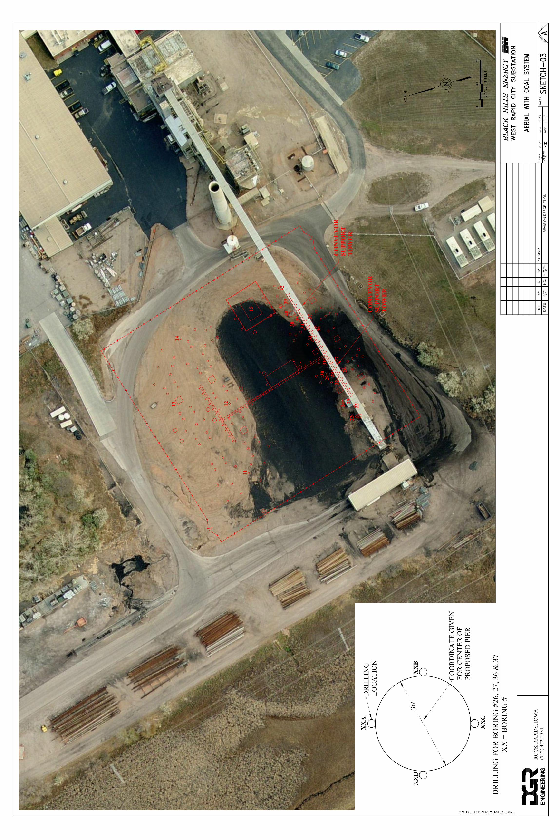
XX
B36
"X
XD
XX
A
XX
C
DR
ILLI
NG
LOC
ATI
ON
DR
ILLI
NG
FO
R B
OR
ING
#26
, 27,
36
& 3
7X
X =
BO
RIN
G #
CO
OR
DIN
ATE
GIV
ENFO
R C
ENTE
R O
FPR
OPO
SED
PIE
R
CO
NV
EY
OR
SUPP
OR
TT
OW
ER
CO
NV
EY
OR
SUPP
OR
TT
OW
ER
21222324 25
32282930
31
2627
36
3733
3435
3840
3941
42
15
1413
11
12
DA
TE
NO
.
BY
DR
AW
N
BY
AP
PR
OV
ED
RE
VIS
IO
N D
ES
CR
IP
TIO
N
DR
AW
N
BY
AP
PR
OV
ED
BY
DA
TE
DA
TE
DW
G N
O.
R
E
V
I
S
I
O
N
N
O
.
S.S. STINKER
A10-18
KLV
PD
KP
RE
LIM
IN
AR
Y
P:\04\233\15\DWG\SKETCH-03.DWG
RO
CK
RA
PID
S, IO
WA
(712
) 472
-253
1
0030'
60'

West Rapid City SubstationBoring Location CoordinatesRev. 11-02-18
Boring # Boring Location(s) Depth Northing Easting Notes:1 Geotech Report Boring B-12 Geotech Report Boring B-23 Geotech Report Boring B-34 Geotech Report Boring B-45 Geotech Report Boring B-56 Geotech Report Boring B-67 Geotech Report Boring B-78 Geotech Report Boring B-89 Geotech Report Boring B-9
10 Geotech Report Boring B-10
11 Additional for Geotech Report 30' 652883.8174 1198680.209 44.0873440°, -103.2638968°12 Additional for Geotech Report 30' 652908.8381 1198769.636 44.0874213°, -103.2635600°13 Additional for Geotech Report 30' 652973.3087 1198773.754 44.0875984°, -103.2635530°14 Additional for Geotech Report 30' 652971.4715 1198853.095 44.0876011°, -103.2632509°15 Additional for Geotech Report 30' 652881.2041 1198892.338 44.0873574°, -103.2630896°
21 Center of proposed pier 18' 652745.4244 1198753.2 44.0869717°, -103.2636006°22 Center of proposed pier 18' 652751.474 1198755.298 44.0869885°, -103.2635934°23 Center of proposed pier 18' 652748.9701 1198766.331 44.0869827°, -103.2635511°24 Center of proposed pier 18' 652757.7977 1198771.625 44.0870074°, -103.2635321°25 Center of proposed pier 18' 652755.8943 1198777.317 44.0870027°, -103.2635102°26 Center of proposed pier N/A 652764.3968 1198813.327 44.0870295°, -103.2633744°
26A N Quadrant of proposed 36" φ pier 18' N/A N/A26B S Quadrant of proposed 36" φ pier 18' N/A N/A26C E Quadrant of proposed 36" φ pier 18' N/A N/A26D W Quadrant of proposed 36" φ pier 18' N/A N/A27 Center of proposed pier N/A 652769.7275 1198821.788 44.0870450°, -103.2633429°
27A N Quadrant of proposed 36" φ pier 18' N/A N/A27B S Quadrant of proposed 36" φ pier 18' N/A N/A27C E Quadrant of proposed 36" φ pier 18' N/A N/A27D W Quadrant of proposed 36" φ pier 18' N/A N/A28 Center of proposed pier 18' 652777.2173 1198811.159 44.0870645°, -103.2633844°29 Center of proposed pier 18' 652783.1398 1198807.428 44.0870803°, -103.2633994°30 Center of proposed pier 18' 652789.0622 1198803.696 44.0870962°, -103.2634144°31 Center of proposed pier 18' 652786.8127 1198826.389 44.0870922°, -103.2633277°32 Center of proposed pier 18' 652770.8204 1198801.006 44.0870459°, -103.2634221°33 Center of proposed pier 18' 652801.7387 1198850.078 44.0871355°, -103.2632396°34 Center of proposed pier 18' 652811.3341 1198865.308 44.0871633°, -103.2631830°35 Center of proposed pier 18' 652817.731 1198875.46 44.0871818°, -103.2631452°36 Quadrants of proposed 36" φ pier 652798.5135 1198867.476 44.0871283°, -103.2631730°
36A N Quadrant of proposed 36" φ pier 18' N/A N/A36B S Quadrant of proposed 36" φ pier 18' N/A N/A36C E Quadrant of proposed 36" φ pier 18' N/A N/A36D W Quadrant of proposed 36" φ pier 18' N/A N/A37 Quadrants of proposed 36" φ pier 652803.8443 1198875.936 44.0871437°, -103.2631416°
37A N Quadrant of proposed 36" φ pier 18' N/A N/A37B S Quadrant of proposed 36" φ pier 18' N/A N/A37C E Quadrant of proposed 36" φ pier 18' N/A N/A37D W Quadrant of proposed 36" φ pier 18' N/A N/A38 Center of proposed pier 18' 652824.4995 1198871.196 44.0871999°, -103.2631624°39 Center of proposed pier 18' 652832.6571 1198899.15 44.0872026°, -103.2630560°40 Center of proposed pad 18' 652828.5614 1198885.151 44.0872124°, -103.2631098°41 Center of proposed pier 18' 652839.4256 1198894.886 44.0872431°, -103.2630743°42 Center of proposed pier 18' 652844.9235 1198918.624 44.0872605°, -103.2629847°

LIMESTONE AGGREGATE SURFACING,10 inchesFILL, Silty Lean Clay with Sand, reddishbrown (CL)FILL, Gypsum boulder
FILL, Silty Lean Clay, reddish brown (CL)
SILTY LEAN CLAY, red-brown (CL)
Bottom of Boring
SURFACIING
FILL
ALLUVIUM
M
W
BORINGCOMPLETED: 11/27/18
CAVE-INDEPTH
11/27/18 17.0
CASINGDEPTH
LG:
30.0
DEPTH:
DRILLINGFLUID LEVELDATE
NA4" FA
SURFACE ELEVATION:
RC-1
DRILLING METHOD NOTE: REFER TO
THE ATTACHED
SHEETS FOR AN
EXPLANATION OF
TERMINOLOGY ON
THIS LOGBT
NA
SAMPLEDDEPTH30.0
WATER LEVEL MEASUREMENTS
TIME
DR:
NA
JR
WATERLEVEL
13:50
Rig:
FIELD & LABORATORY TESTSMC
DEN
1
2
3
4
5
6
7
8
9
10
11
12
13
14
15
16
17
18
19
20
21
22
23
24
25
26
27
28
29
30
DEPTHIN
FEET WC PLLL %-#200N REC
IN.
03/2011 01-DHR-060
17-03356
AMERICANENGINEERINGTESTING, INC.
SUBSURFACE BORING LOG
SAMPLETYPE
GEOLOGY
West Rapid Substation; Rapid City, South Dakota
MATERIAL DESCRIPTION
AET JOB NO:
PROJECT:
B-11 (p. 1 of 1)LOG OF BORING NO.
AE
T_C
OR
P
17-0
3356
.GP
J A
ET
+C
PT
+W
ELL
.GD
T
12/3
/18
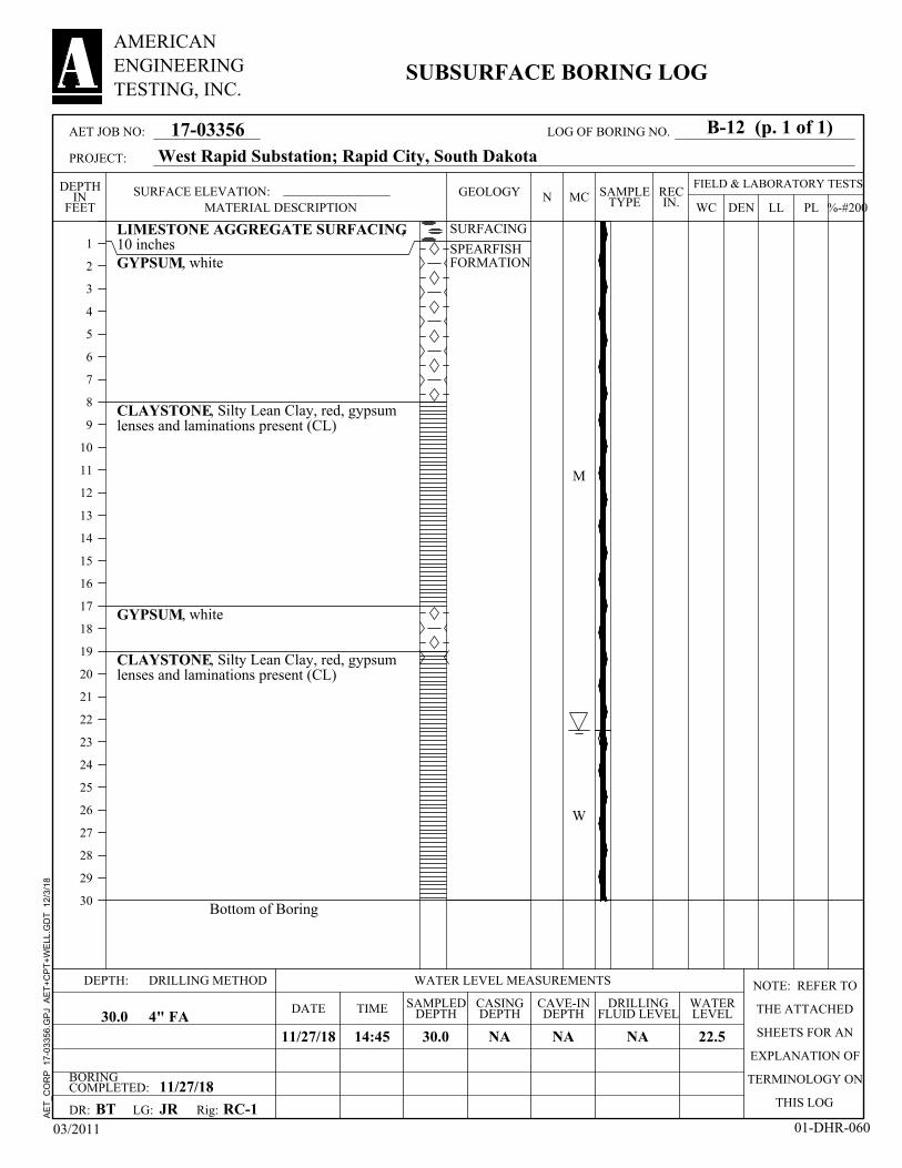
LIMESTONE AGGREGATE SURFACING,10 inchesGYPSUM, white
CLAYSTONE, Silty Lean Clay, red, gypsumlenses and laminations present (CL)
GYPSUM, white
CLAYSTONE, Silty Lean Clay, red, gypsumlenses and laminations present (CL)
Bottom of Boring
SURFACING
SPEARFISHFORMATION
M
W
BORINGCOMPLETED: 11/27/18
CAVE-INDEPTH
11/27/18 22.5
CASINGDEPTH
LG:
30.0
DEPTH:
DRILLINGFLUID LEVELDATE
NA4" FA
SURFACE ELEVATION:
RC-1
DRILLING METHOD NOTE: REFER TO
THE ATTACHED
SHEETS FOR AN
EXPLANATION OF
TERMINOLOGY ON
THIS LOGBT
NA
SAMPLEDDEPTH30.0
WATER LEVEL MEASUREMENTS
TIME
DR:
NA
JR
WATERLEVEL
14:45
Rig:
FIELD & LABORATORY TESTSMC
DEN
1
2
3
4
5
6
7
8
9
10
11
12
13
14
15
16
17
18
19
20
21
22
23
24
25
26
27
28
29
30
DEPTHIN
FEET WC PLLL %-#200N REC
IN.
03/2011 01-DHR-060
17-03356
AMERICANENGINEERINGTESTING, INC.
SUBSURFACE BORING LOG
SAMPLETYPE
GEOLOGY
West Rapid Substation; Rapid City, South Dakota
MATERIAL DESCRIPTION
AET JOB NO:
PROJECT:
B-12 (p. 1 of 1)LOG OF BORING NO.
AE
T_C
OR
P
17-0
3356
.GP
J A
ET
+C
PT
+W
ELL
.GD
T
12/3
/18

LIMESTONE AGGREGATE SURFACING,10 inchesFILL, Silty Lean Clay with Sand, reddishbrown (CL)
GYPSUM, white
CLAYSTONE, Silty Lean Clay, red, gypsumlenses and laminations present (CL)
color grading to reddish brown
Bottom of Boring
SURFACIING
FILL
SPEARFISHFORMATION
M
BORINGCOMPLETED: 11/27/18
CAVE-INDEPTH
11/27/18 None
CASINGDEPTH
LG:
30.0
DEPTH:
DRILLINGFLUID LEVELDATE
NA4" FA
SURFACE ELEVATION:
RC-1
DRILLING METHOD NOTE: REFER TO
THE ATTACHED
SHEETS FOR AN
EXPLANATION OF
TERMINOLOGY ON
THIS LOGBT
NA
SAMPLEDDEPTH30.0
WATER LEVEL MEASUREMENTS
TIME
DR:
NA
JR
WATERLEVEL
15:25
Rig:
FIELD & LABORATORY TESTSMC
DEN
1
2
3
4
5
6
7
8
9
10
11
12
13
14
15
16
17
18
19
20
21
22
23
24
25
26
27
28
29
30
DEPTHIN
FEET WC PLLL %-#200N REC
IN.
03/2011 01-DHR-060
17-03356
AMERICANENGINEERINGTESTING, INC.
SUBSURFACE BORING LOG
SAMPLETYPE
GEOLOGY
West Rapid Substation; Rapid City, South Dakota
MATERIAL DESCRIPTION
AET JOB NO:
PROJECT:
B-13 (p. 1 of 1)LOG OF BORING NO.
AE
T_C
OR
P
17-0
3356
.GP
J A
ET
+C
PT
+W
ELL
.GD
T
12/3
/18
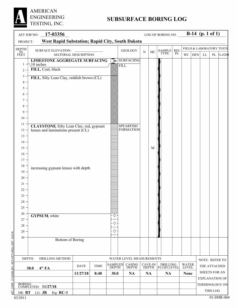
LIMESTONE AGGREGATE SURFACING,10 inchesFILL, Coal, black
FILL, Silty Lean Clay, reddish brown (CL)
CLAYSTONE, Silty Lean Clay, red, gypsumlenses and laminations present (CL)
increasing gypsum lenses with depth
GYPSUM, white
Bottom of Boring
SURFACIING
FILL
SPEARFISHFORMATION
M
BORINGCOMPLETED: 11/27/18
CAVE-INDEPTH
11/27/18 None
CASINGDEPTH
LG:
30.0
DEPTH:
DRILLINGFLUID LEVELDATE
NA4" FA
SURFACE ELEVATION:
RC-1
DRILLING METHOD NOTE: REFER TO
THE ATTACHED
SHEETS FOR AN
EXPLANATION OF
TERMINOLOGY ON
THIS LOGBT
NA
SAMPLEDDEPTH30.0
WATER LEVEL MEASUREMENTS
TIME
DR:
NA
JR
WATERLEVEL
8:40
Rig:
FIELD & LABORATORY TESTSMC
DEN
1
2
3
4
5
6
7
8
9
10
11
12
13
14
15
16
17
18
19
20
21
22
23
24
25
26
27
28
29
30
DEPTHIN
FEET WC PLLL %-#200N REC
IN.
03/2011 01-DHR-060
17-03356
AMERICANENGINEERINGTESTING, INC.
SUBSURFACE BORING LOG
SAMPLETYPE
GEOLOGY
West Rapid Substation; Rapid City, South Dakota
MATERIAL DESCRIPTION
AET JOB NO:
PROJECT:
B-14 (p. 1 of 1)LOG OF BORING NO.
AE
T_C
OR
P
17-0
3356
.GP
J A
ET
+C
PT
+W
ELL
.GD
T
12/3
/18

LIMESTONE AGGREGATE SURFACING,10 inchesFILL, Silty Lean Clay, dark reddish brown toblack (CL)
LEAN CLAY, brown (CL)
SILTY LEAN CLAY, reddish brown (CL)
Bottom of Boring
SURFACIING
FILL
ALLUVIUM
M
W
BORINGCOMPLETED: 11/27/18
CAVE-INDEPTH
11/27/18 18.0
CASINGDEPTH
LG:
30.0
DEPTH:
DRILLINGFLUID LEVELDATE
NA4" FA
SURFACE ELEVATION:
RC-1
DRILLING METHOD NOTE: REFER TO
THE ATTACHED
SHEETS FOR AN
EXPLANATION OF
TERMINOLOGY ON
THIS LOGBT
NA
SAMPLEDDEPTH30.0
WATER LEVEL MEASUREMENTS
TIME
DR:
NA
JR
WATERLEVEL
16:10
Rig:
FIELD & LABORATORY TESTSMC
DEN
1
2
3
4
5
6
7
8
9
10
11
12
13
14
15
16
17
18
19
20
21
22
23
24
25
26
27
28
29
30
DEPTHIN
FEET WC PLLL %-#200N REC
IN.
03/2011 01-DHR-060
17-03356
AMERICANENGINEERINGTESTING, INC.
SUBSURFACE BORING LOG
SAMPLETYPE
GEOLOGY
West Rapid Substation; Rapid City, South Dakota
MATERIAL DESCRIPTION
AET JOB NO:
PROJECT:
B-15 (p. 1 of 1)LOG OF BORING NO.
AE
T_C
OR
P
17-0
3356
.GP
J A
ET
+C
PT
+W
ELL
.GD
T
12/3
/18
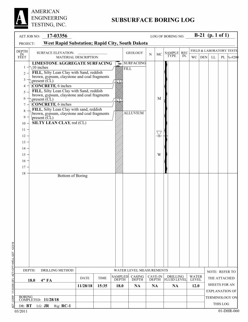
LIMESTONE AGGREGATE SURFACING,10 inchesFILL, Silty Lean Clay with Sand, reddishbrown, gypsum, claystone and coal fragmentspresent (CL)CONCRETE, 6 inchesFILL, Silty Lean Clay with Sand, reddishbrown, gypsum, claystone and coal fragmentspresent (CL)CONCRETE, 6 inchesFILL, Silty Lean Clay with sand, reddishbrown, gypsum, claystone and coal fragmentspresent (CL)SILTY LEAN CLAY, red (CL)
Bottom of Boring
SURFACIING
FILL
ALLUVIUM
M
W
BORINGCOMPLETED: 11/28/18
CAVE-INDEPTH
11/28/18 12.0
CASINGDEPTH
LG:
18.0
DEPTH:
DRILLINGFLUID LEVELDATE
NA4" FA
SURFACE ELEVATION:
RC-1
DRILLING METHOD NOTE: REFER TO
THE ATTACHED
SHEETS FOR AN
EXPLANATION OF
TERMINOLOGY ON
THIS LOGBT
NA
SAMPLEDDEPTH18.0
WATER LEVEL MEASUREMENTS
TIME
DR:
NA
JR
WATERLEVEL
15:35
Rig:
FIELD & LABORATORY TESTSMC
DEN
1
2
3
4
5
6
7
8
9
10
11
12
13
14
15
16
17
18
DEPTHIN
FEET WC PLLL %-#200N REC
IN.
03/2011 01-DHR-060
17-03356
AMERICANENGINEERINGTESTING, INC.
SUBSURFACE BORING LOG
SAMPLETYPE
GEOLOGY
West Rapid Substation; Rapid City, South Dakota
MATERIAL DESCRIPTION
AET JOB NO:
PROJECT:
B-21 (p. 1 of 1)LOG OF BORING NO.
AE
T_C
OR
P
17-0
3356
.GP
J A
ET
+C
PT
+W
ELL
.GD
T
12/3
/18
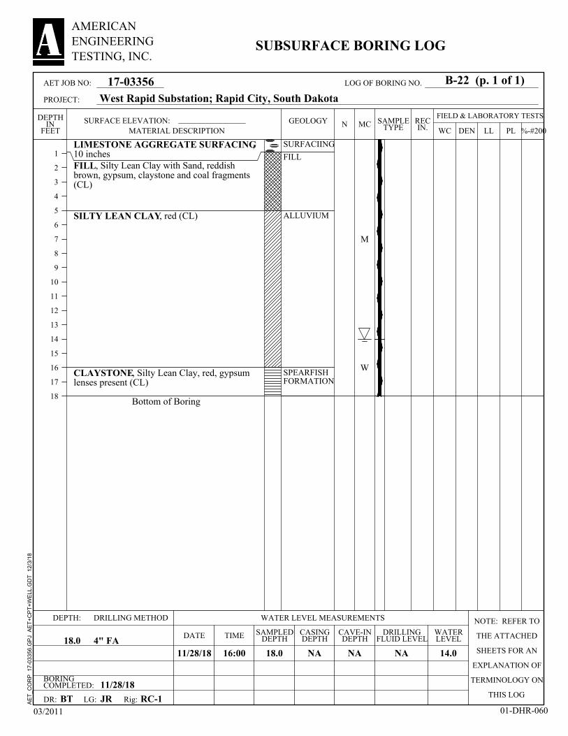
LIMESTONE AGGREGATE SURFACING,10 inchesFILL, Silty Lean Clay with Sand, reddishbrown, gypsum, claystone and coal fragments(CL)
SILTY LEAN CLAY, red (CL)
CLAYSTONE, Silty Lean Clay, red, gypsumlenses present (CL)
Bottom of Boring
SURFACIING
FILL
ALLUVIUM
SPEARFISHFORMATION
M
W
BORINGCOMPLETED: 11/28/18
CAVE-INDEPTH
11/28/18 14.0
CASINGDEPTH
LG:
18.0
DEPTH:
DRILLINGFLUID LEVELDATE
NA4" FA
SURFACE ELEVATION:
RC-1
DRILLING METHOD NOTE: REFER TO
THE ATTACHED
SHEETS FOR AN
EXPLANATION OF
TERMINOLOGY ON
THIS LOGBT
NA
SAMPLEDDEPTH18.0
WATER LEVEL MEASUREMENTS
TIME
DR:
NA
JR
WATERLEVEL
16:00
Rig:
FIELD & LABORATORY TESTSMC
DEN
1
2
3
4
5
6
7
8
9
10
11
12
13
14
15
16
17
18
DEPTHIN
FEET WC PLLL %-#200N REC
IN.
03/2011 01-DHR-060
17-03356
AMERICANENGINEERINGTESTING, INC.
SUBSURFACE BORING LOG
SAMPLETYPE
GEOLOGY
West Rapid Substation; Rapid City, South Dakota
MATERIAL DESCRIPTION
AET JOB NO:
PROJECT:
B-22 (p. 1 of 1)LOG OF BORING NO.
AE
T_C
OR
P
17-0
3356
.GP
J A
ET
+C
PT
+W
ELL
.GD
T
12/3
/18
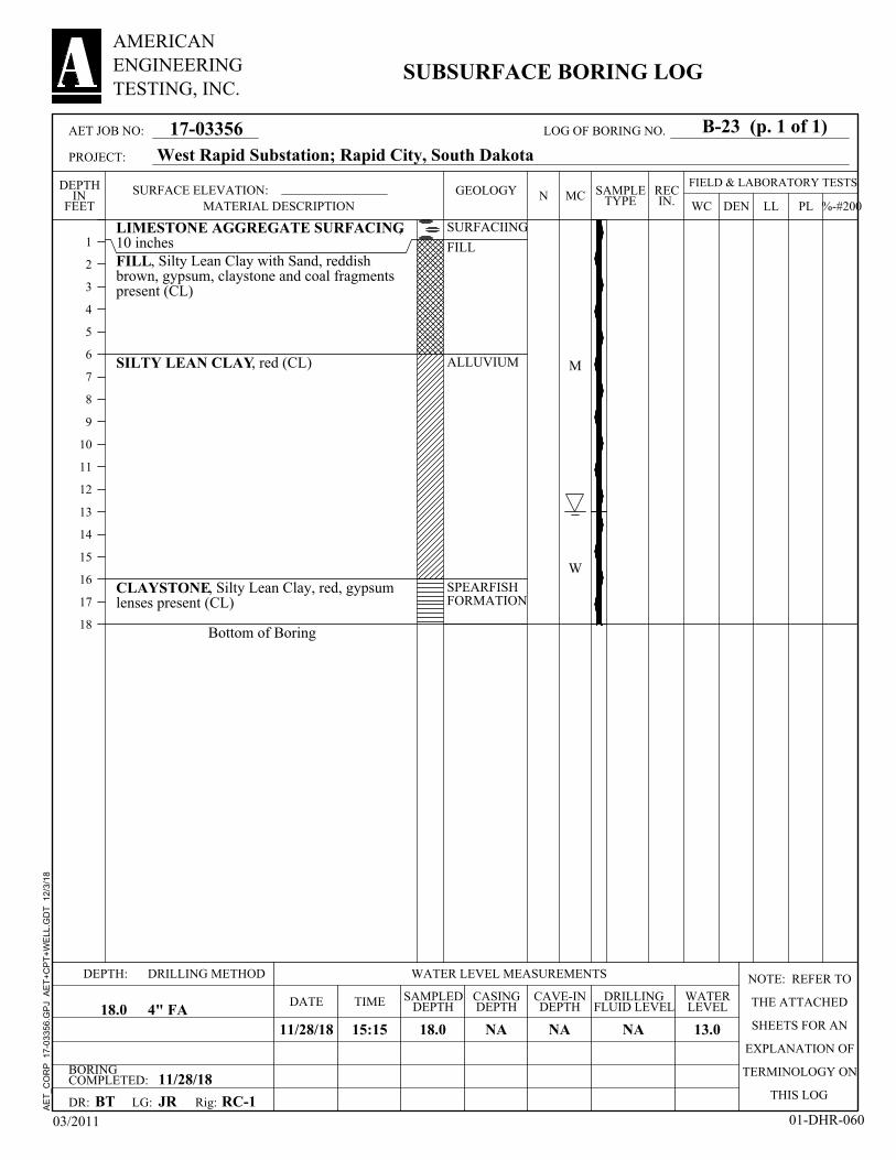
LIMESTONE AGGREGATE SURFACING,10 inchesFILL, Silty Lean Clay with Sand, reddishbrown, gypsum, claystone and coal fragmentspresent (CL)
SILTY LEAN CLAY, red (CL)
CLAYSTONE, Silty Lean Clay, red, gypsumlenses present (CL)
Bottom of Boring
SURFACIING
FILL
ALLUVIUM
SPEARFISHFORMATION
M
W
BORINGCOMPLETED: 11/28/18
CAVE-INDEPTH
11/28/18 13.0
CASINGDEPTH
LG:
18.0
DEPTH:
DRILLINGFLUID LEVELDATE
NA4" FA
SURFACE ELEVATION:
RC-1
DRILLING METHOD NOTE: REFER TO
THE ATTACHED
SHEETS FOR AN
EXPLANATION OF
TERMINOLOGY ON
THIS LOGBT
NA
SAMPLEDDEPTH18.0
WATER LEVEL MEASUREMENTS
TIME
DR:
NA
JR
WATERLEVEL
15:15
Rig:
FIELD & LABORATORY TESTSMC
DEN
1
2
3
4
5
6
7
8
9
10
11
12
13
14
15
16
17
18
DEPTHIN
FEET WC PLLL %-#200N REC
IN.
03/2011 01-DHR-060
17-03356
AMERICANENGINEERINGTESTING, INC.
SUBSURFACE BORING LOG
SAMPLETYPE
GEOLOGY
West Rapid Substation; Rapid City, South Dakota
MATERIAL DESCRIPTION
AET JOB NO:
PROJECT:
B-23 (p. 1 of 1)LOG OF BORING NO.
AE
T_C
OR
P
17-0
3356
.GP
J A
ET
+C
PT
+W
ELL
.GD
T
12/3
/18

LIMESTONE AGGREGATE SURFACING,10 inchesFILL, Silty Lean Clay with Sand, reddishbrown, gypsum, claystone and coal fragmentspresent (CL)
SILTY LEAN CLAY, red (CL)
CLAYSTONE, Silty Lean Clay, red, gypsumlenses present (CL)
Bottom of Boring
SURFACIING
FILL
ALLUVIUM
SPEARFISHFORMATION
M
W
BORINGCOMPLETED: 11/28/18
CAVE-INDEPTH
11/28/18 15.0
CASINGDEPTH
LG:
18.0
DEPTH:
DRILLINGFLUID LEVELDATE
NA4" FA
SURFACE ELEVATION:
RC-1
DRILLING METHOD NOTE: REFER TO
THE ATTACHED
SHEETS FOR AN
EXPLANATION OF
TERMINOLOGY ON
THIS LOGBT
NA
SAMPLEDDEPTH18.0
WATER LEVEL MEASUREMENTS
TIME
DR:
NA
JR
WATERLEVEL
15:00
Rig:
FIELD & LABORATORY TESTSMC
DEN
1
2
3
4
5
6
7
8
9
10
11
12
13
14
15
16
17
18
DEPTHIN
FEET WC PLLL %-#200N REC
IN.
03/2011 01-DHR-060
17-03356
AMERICANENGINEERINGTESTING, INC.
SUBSURFACE BORING LOG
SAMPLETYPE
GEOLOGY
West Rapid Substation; Rapid City, South Dakota
MATERIAL DESCRIPTION
AET JOB NO:
PROJECT:
B-24 (p. 1 of 1)LOG OF BORING NO.
AE
T_C
OR
P
17-0
3356
.GP
J A
ET
+C
PT
+W
ELL
.GD
T
12/3
/18
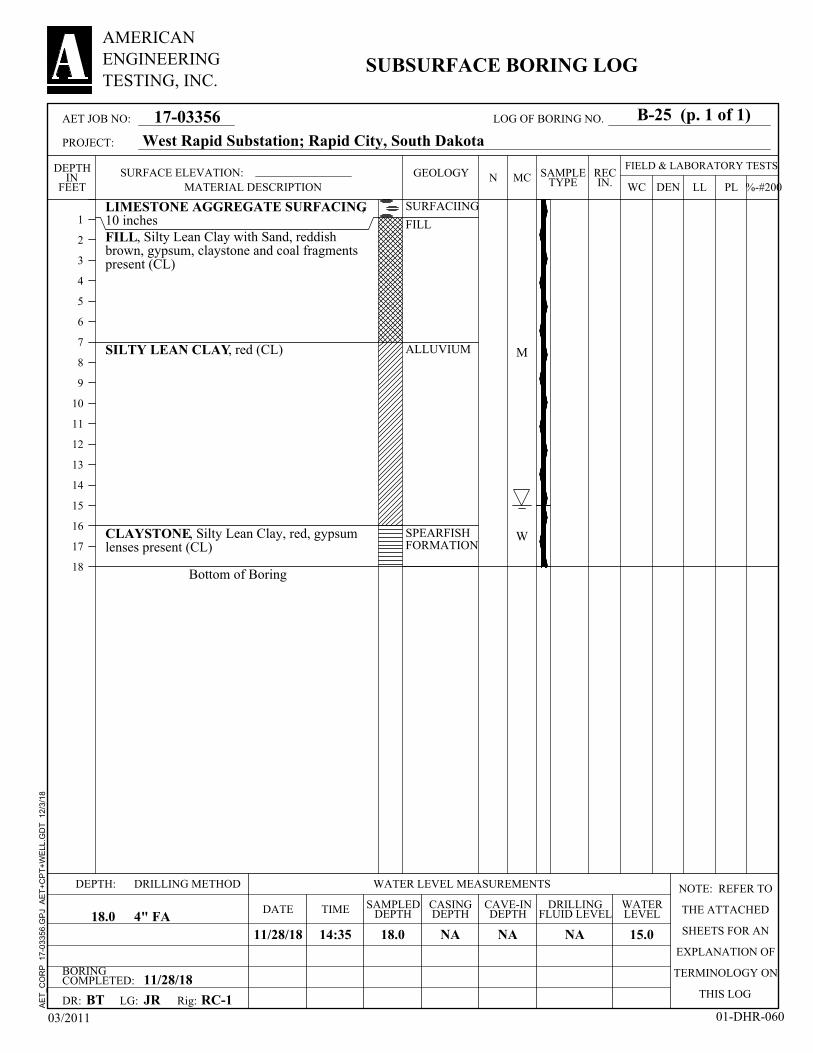
LIMESTONE AGGREGATE SURFACING,10 inchesFILL, Silty Lean Clay with Sand, reddishbrown, gypsum, claystone and coal fragmentspresent (CL)
SILTY LEAN CLAY, red (CL)
CLAYSTONE, Silty Lean Clay, red, gypsumlenses present (CL)
Bottom of Boring
SURFACIING
FILL
ALLUVIUM
SPEARFISHFORMATION
M
W
BORINGCOMPLETED: 11/28/18
CAVE-INDEPTH
11/28/18 15.0
CASINGDEPTH
LG:
18.0
DEPTH:
DRILLINGFLUID LEVELDATE
NA4" FA
SURFACE ELEVATION:
RC-1
DRILLING METHOD NOTE: REFER TO
THE ATTACHED
SHEETS FOR AN
EXPLANATION OF
TERMINOLOGY ON
THIS LOGBT
NA
SAMPLEDDEPTH18.0
WATER LEVEL MEASUREMENTS
TIME
DR:
NA
JR
WATERLEVEL
14:35
Rig:
FIELD & LABORATORY TESTSMC
DEN
1
2
3
4
5
6
7
8
9
10
11
12
13
14
15
16
17
18
DEPTHIN
FEET WC PLLL %-#200N REC
IN.
03/2011 01-DHR-060
17-03356
AMERICANENGINEERINGTESTING, INC.
SUBSURFACE BORING LOG
SAMPLETYPE
GEOLOGY
West Rapid Substation; Rapid City, South Dakota
MATERIAL DESCRIPTION
AET JOB NO:
PROJECT:
B-25 (p. 1 of 1)LOG OF BORING NO.
AE
T_C
OR
P
17-0
3356
.GP
J A
ET
+C
PT
+W
ELL
.GD
T
12/3
/18
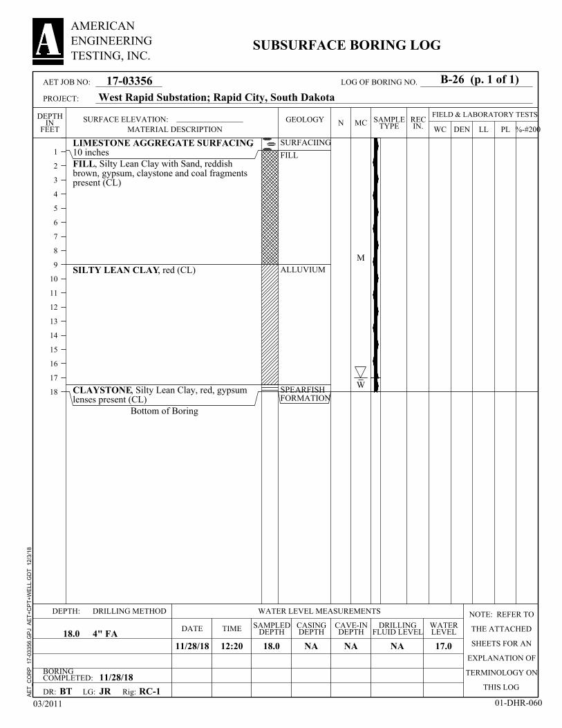
LIMESTONE AGGREGATE SURFACING,10 inchesFILL, Silty Lean Clay with Sand, reddishbrown, gypsum, claystone and coal fragmentspresent (CL)
SILTY LEAN CLAY, red (CL)
CLAYSTONE, Silty Lean Clay, red, gypsumlenses present (CL)
Bottom of Boring
SURFACIING
FILL
ALLUVIUM
SPEARFISHFORMATION
M
W
BORINGCOMPLETED: 11/28/18
CAVE-INDEPTH
11/28/18 17.0
CASINGDEPTH
LG:
18.0
DEPTH:
DRILLINGFLUID LEVELDATE
NA4" FA
SURFACE ELEVATION:
RC-1
DRILLING METHOD NOTE: REFER TO
THE ATTACHED
SHEETS FOR AN
EXPLANATION OF
TERMINOLOGY ON
THIS LOGBT
NA
SAMPLEDDEPTH18.0
WATER LEVEL MEASUREMENTS
TIME
DR:
NA
JR
WATERLEVEL
12:20
Rig:
FIELD & LABORATORY TESTSMC
DEN
1
2
3
4
5
6
7
8
9
10
11
12
13
14
15
16
17
18
DEPTHIN
FEET WC PLLL %-#200N REC
IN.
03/2011 01-DHR-060
17-03356
AMERICANENGINEERINGTESTING, INC.
SUBSURFACE BORING LOG
SAMPLETYPE
GEOLOGY
West Rapid Substation; Rapid City, South Dakota
MATERIAL DESCRIPTION
AET JOB NO:
PROJECT:
B-26 (p. 1 of 1)LOG OF BORING NO.
AE
T_C
OR
P
17-0
3356
.GP
J A
ET
+C
PT
+W
ELL
.GD
T
12/3
/18

LIMESTONE AGGREGATE SURFACING,10 inchesFILL, Silty Lean Clay with Sand, reddishbrown, gypsum, claystone and coal fragmentspresent (CL)
SILTY LEAN CLAY, red (CL)
CLAYSTONE, Silty Lean Clay, red, gypsumlenses present (CL)
Bottom of Boring
SURFACIING
FILL
ALLUVIUM
SPEARFISHFORMATION
M
W
BORINGCOMPLETED: 11/28/18
CAVE-INDEPTH
11/28/18 17.0
CASINGDEPTH
LG:
18.0
DEPTH:
DRILLINGFLUID LEVELDATE
NA4" FA
SURFACE ELEVATION:
RC-1
DRILLING METHOD NOTE: REFER TO
THE ATTACHED
SHEETS FOR AN
EXPLANATION OF
TERMINOLOGY ON
THIS LOGBT
NA
SAMPLEDDEPTH18.0
WATER LEVEL MEASUREMENTS
TIME
DR:
NA
JR
WATERLEVEL
12:05
Rig:
FIELD & LABORATORY TESTSMC
DEN
1
2
3
4
5
6
7
8
9
10
11
12
13
14
15
16
17
18
DEPTHIN
FEET WC PLLL %-#200N REC
IN.
03/2011 01-DHR-060
17-03356
AMERICANENGINEERINGTESTING, INC.
SUBSURFACE BORING LOG
SAMPLETYPE
GEOLOGY
West Rapid Substation; Rapid City, South Dakota
MATERIAL DESCRIPTION
AET JOB NO:
PROJECT:
B-26A (p. 1 of 1)LOG OF BORING NO.
AE
T_C
OR
P
17-0
3356
.GP
J A
ET
+C
PT
+W
ELL
.GD
T
12/3
/18

LIMESTONE AGGREGATE SURFACING,10 inchesFILL, Silty Lean Clay with Sand, reddishbrown, gypsum, claystone and coal fragmentspresent (CL)
SILTY LEAN CLAY, red (CL)
CLAYSTONE, Silty Lean Clay, red, gypsumlenses present (CL)
Bottom of Boring
SURFACIING
FILL
ALLUVIUM
SPEARFISHFORMATION
M
W
BORINGCOMPLETED: 11/28/18
CAVE-INDEPTH
11/28/18 17.0
CASINGDEPTH
LG:
18.0
DEPTH:
DRILLINGFLUID LEVELDATE
NA4" FA
SURFACE ELEVATION:
RC-1
DRILLING METHOD NOTE: REFER TO
THE ATTACHED
SHEETS FOR AN
EXPLANATION OF
TERMINOLOGY ON
THIS LOGBT
NA
SAMPLEDDEPTH18.0
WATER LEVEL MEASUREMENTS
TIME
DR:
NA
JR
WATERLEVEL
12:55
Rig:
FIELD & LABORATORY TESTSMC
DEN
1
2
3
4
5
6
7
8
9
10
11
12
13
14
15
16
17
18
DEPTHIN
FEET WC PLLL %-#200N REC
IN.
03/2011 01-DHR-060
17-03356
AMERICANENGINEERINGTESTING, INC.
SUBSURFACE BORING LOG
SAMPLETYPE
GEOLOGY
West Rapid Substation; Rapid City, South Dakota
MATERIAL DESCRIPTION
AET JOB NO:
PROJECT:
B-26B (p. 1 of 1)LOG OF BORING NO.
AE
T_C
OR
P
17-0
3356
.GP
J A
ET
+C
PT
+W
ELL
.GD
T
12/3
/18

LIMESTONE AGGREGATE SURFACING,10 inchesFILL, Silty Lean Clay with Sand, reddishbrown, gypsum, claystone and coal fragmentspresent (CL)
SILTY LEAN CLAY, red (CL)
CLAYSTONE, Silty Lean Clay, red, gypsumlenses present (CL)
Bottom of Boring
SURFACIING
FILL
ALLUVIUM
SPEARFISHFORMATION
M
W
BORINGCOMPLETED: 11/28/18
CAVE-INDEPTH
11/28/18 17.0
CASINGDEPTH
LG:
18.0
DEPTH:
DRILLINGFLUID LEVELDATE
NA4" FA
SURFACE ELEVATION:
RC-1
DRILLING METHOD NOTE: REFER TO
THE ATTACHED
SHEETS FOR AN
EXPLANATION OF
TERMINOLOGY ON
THIS LOGBT
NA
SAMPLEDDEPTH18.0
WATER LEVEL MEASUREMENTS
TIME
DR:
NA
JR
WATERLEVEL
13:35
Rig:
FIELD & LABORATORY TESTSMC
DEN
1
2
3
4
5
6
7
8
9
10
11
12
13
14
15
16
17
18
DEPTHIN
FEET WC PLLL %-#200N REC
IN.
03/2011 01-DHR-060
17-03356
AMERICANENGINEERINGTESTING, INC.
SUBSURFACE BORING LOG
SAMPLETYPE
GEOLOGY
West Rapid Substation; Rapid City, South Dakota
MATERIAL DESCRIPTION
AET JOB NO:
PROJECT:
B-26C (p. 1 of 1)LOG OF BORING NO.
AE
T_C
OR
P
17-0
3356
.GP
J A
ET
+C
PT
+W
ELL
.GD
T
12/3
/18

LIMESTONE AGGREGATE SURFACING,10 inchesFILL, Silty Lean Clay with Sand, reddishbrown, gypsum, claystone and coal fragmentspresent (CL)
SILTY LEAN CLAY, red (CL)
CLAYSTONE, Silty Lean Clay, red, gypsumlenses present (CL)
Bottom of Boring
SURFACIING
FILL
ALLUVIUM
SPEARFISHFORMATION
M
W
BORINGCOMPLETED: 11/28/18
CAVE-INDEPTH
11/28/18 17.0
CASINGDEPTH
LG:
18.0
DEPTH:
DRILLINGFLUID LEVELDATE
NA4" FA
SURFACE ELEVATION:
RC-1
DRILLING METHOD NOTE: REFER TO
THE ATTACHED
SHEETS FOR AN
EXPLANATION OF
TERMINOLOGY ON
THIS LOGBT
NA
SAMPLEDDEPTH18.0
WATER LEVEL MEASUREMENTS
TIME
DR:
NA
JR
WATERLEVEL
12:25
Rig:
FIELD & LABORATORY TESTSMC
DEN
1
2
3
4
5
6
7
8
9
10
11
12
13
14
15
16
17
18
DEPTHIN
FEET WC PLLL %-#200N REC
IN.
03/2011 01-DHR-060
17-03356
AMERICANENGINEERINGTESTING, INC.
SUBSURFACE BORING LOG
SAMPLETYPE
GEOLOGY
West Rapid Substation; Rapid City, South Dakota
MATERIAL DESCRIPTION
AET JOB NO:
PROJECT:
B-26D (p. 1 of 1)LOG OF BORING NO.
AE
T_C
OR
P
17-0
3356
.GP
J A
ET
+C
PT
+W
ELL
.GD
T
12/3
/18
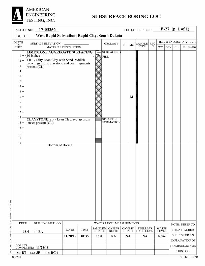
LIMESTONE AGGREGATE SURFACING,10 inchesFILL, Silty Lean Clay with Sand, reddishbrown, gypsum, claystone and coal fragmentspresent (CL)
CLAYSTONE, Silty Lean Clay, red, gypsumlenses present (CL)
Bottom of Boring
SURFACIING
FILL
SPEARFISHFORMATION
M
BORINGCOMPLETED: 11/28/18
CAVE-INDEPTH
11/28/18 None
CASINGDEPTH
LG:
18.0
DEPTH:
DRILLINGFLUID LEVELDATE
NA4" FA
SURFACE ELEVATION:
RC-1
DRILLING METHOD NOTE: REFER TO
THE ATTACHED
SHEETS FOR AN
EXPLANATION OF
TERMINOLOGY ON
THIS LOGBT
NA
SAMPLEDDEPTH18.0
WATER LEVEL MEASUREMENTS
TIME
DR:
NA
JR
WATERLEVEL
10:35
Rig:
FIELD & LABORATORY TESTSMC
DEN
1
2
3
4
5
6
7
8
9
10
11
12
13
14
15
16
17
18
DEPTHIN
FEET WC PLLL %-#200N REC
IN.
03/2011 01-DHR-060
17-03356
AMERICANENGINEERINGTESTING, INC.
SUBSURFACE BORING LOG
SAMPLETYPE
GEOLOGY
West Rapid Substation; Rapid City, South Dakota
MATERIAL DESCRIPTION
AET JOB NO:
PROJECT:
B-27 (p. 1 of 1)LOG OF BORING NO.
AE
T_C
OR
P
17-0
3356
.GP
J A
ET
+C
PT
+W
ELL
.GD
T
12/3
/18

LIMESTONE AGGREGATE SURFACING,10 inchesFILL, Silty Lean Clay with Sand, reddishbrown, gypsum, claystone and coal fragmentspresent (CL)
CLAYSTONE, Silty Lean Clay, red, gypsumlenses present (CL)
Bottom of Boring
SURFACIING
FILL
SPEARFISHFORMATION
M
BORINGCOMPLETED: 11/28/18
CAVE-INDEPTH
11/28/18 None
CASINGDEPTH
LG:
18.0
DEPTH:
DRILLINGFLUID LEVELDATE
NA4" FA
SURFACE ELEVATION:
RC-1
DRILLING METHOD NOTE: REFER TO
THE ATTACHED
SHEETS FOR AN
EXPLANATION OF
TERMINOLOGY ON
THIS LOGBT
NA
SAMPLEDDEPTH18.0
WATER LEVEL MEASUREMENTS
TIME
DR:
NA
JR
WATERLEVEL
10:55
Rig:
FIELD & LABORATORY TESTSMC
DEN
1
2
3
4
5
6
7
8
9
10
11
12
13
14
15
16
17
18
DEPTHIN
FEET WC PLLL %-#200N REC
IN.
03/2011 01-DHR-060
17-03356
AMERICANENGINEERINGTESTING, INC.
SUBSURFACE BORING LOG
SAMPLETYPE
GEOLOGY
West Rapid Substation; Rapid City, South Dakota
MATERIAL DESCRIPTION
AET JOB NO:
PROJECT:
B-27A (p. 1 of 1)LOG OF BORING NO.
AE
T_C
OR
P
17-0
3356
.GP
J A
ET
+C
PT
+W
ELL
.GD
T
12/3
/18

LIMESTONE AGGREGATE SURFACING,10 inchesFILL, Silty Lean Clay with Sand, reddishbrown, gypsum, claystone and coal fragmentspresent (CL)
CLAYSTONE, Silty Lean Clay, red, gypsumlenses present (CL)
Bottom of Boring
SURFACIING
FILL
SPEARFISHFORMATION
M
BORINGCOMPLETED: 11/28/18
CAVE-INDEPTH
11/28/18 None
CASINGDEPTH
LG:
18.0
DEPTH:
DRILLINGFLUID LEVELDATE
NA4" FA
SURFACE ELEVATION:
RC-1
DRILLING METHOD NOTE: REFER TO
THE ATTACHED
SHEETS FOR AN
EXPLANATION OF
TERMINOLOGY ON
THIS LOGBT
NA
SAMPLEDDEPTH18.0
WATER LEVEL MEASUREMENTS
TIME
DR:
NA
JR
WATERLEVEL
11:18
Rig:
FIELD & LABORATORY TESTSMC
DEN
1
2
3
4
5
6
7
8
9
10
11
12
13
14
15
16
17
18
DEPTHIN
FEET WC PLLL %-#200N REC
IN.
03/2011 01-DHR-060
17-03356
AMERICANENGINEERINGTESTING, INC.
SUBSURFACE BORING LOG
SAMPLETYPE
GEOLOGY
West Rapid Substation; Rapid City, South Dakota
MATERIAL DESCRIPTION
AET JOB NO:
PROJECT:
B-27B (p. 1 of 1)LOG OF BORING NO.
AE
T_C
OR
P
17-0
3356
.GP
J A
ET
+C
PT
+W
ELL
.GD
T
12/3
/18

LIMESTONE AGGREGATE SURFACING,10 inchesFILL, Silty Lean Clay with Sand, reddishbrown, gypsum, claystone and coal fragmentspresent (CL)
CLAYSTONE, Silty Lean Clay, red, gypsumlenses present (CL)
Bottom of Boring
SURFACIING
FILL
SPEARFISHFORMATION
M
BORINGCOMPLETED: 11/28/18
CAVE-INDEPTH
11/28/18 None
CASINGDEPTH
LG:
18.0
DEPTH:
DRILLINGFLUID LEVELDATE
NA4" FA
SURFACE ELEVATION:
RC-1
DRILLING METHOD NOTE: REFER TO
THE ATTACHED
SHEETS FOR AN
EXPLANATION OF
TERMINOLOGY ON
THIS LOGBT
NA
SAMPLEDDEPTH18.0
WATER LEVEL MEASUREMENTS
TIME
DR:
NA
JR
WATERLEVEL
11:40
Rig:
FIELD & LABORATORY TESTSMC
DEN
1
2
3
4
5
6
7
8
9
10
11
12
13
14
15
16
17
18
DEPTHIN
FEET WC PLLL %-#200N REC
IN.
03/2011 01-DHR-060
17-03356
AMERICANENGINEERINGTESTING, INC.
SUBSURFACE BORING LOG
SAMPLETYPE
GEOLOGY
West Rapid Substation; Rapid City, South Dakota
MATERIAL DESCRIPTION
AET JOB NO:
PROJECT:
B-27C (p. 1 of 1)LOG OF BORING NO.
AE
T_C
OR
P
17-0
3356
.GP
J A
ET
+C
PT
+W
ELL
.GD
T
12/3
/18

LIMESTONE AGGREGATE SURFACING,10 inchesFILL, Silty Lean Clay with Sand, reddishbrown, gypsum, claystone and coal fragmentspresent (CL)
CLAYSTONE, Silty Lean Clay, red, gypsumlenses present (CL)
Bottom of Boring
SURFACIING
FILL
SPEARFISHFORMATION
M
BORINGCOMPLETED: 11/28/18
CAVE-INDEPTH
11/28/18 None
CASINGDEPTH
LG:
18.0
DEPTH:
DRILLINGFLUID LEVELDATE
NA4" FA
SURFACE ELEVATION:
RC-1
DRILLING METHOD NOTE: REFER TO
THE ATTACHED
SHEETS FOR AN
EXPLANATION OF
TERMINOLOGY ON
THIS LOGBT
NA
SAMPLEDDEPTH18.0
WATER LEVEL MEASUREMENTS
TIME
DR:
NA
JR
WATERLEVEL
11:10
Rig:
FIELD & LABORATORY TESTSMC
DEN
1
2
3
4
5
6
7
8
9
10
11
12
13
14
15
16
17
18
DEPTHIN
FEET WC PLLL %-#200N REC
IN.
03/2011 01-DHR-060
17-03356
AMERICANENGINEERINGTESTING, INC.
SUBSURFACE BORING LOG
SAMPLETYPE
GEOLOGY
West Rapid Substation; Rapid City, South Dakota
MATERIAL DESCRIPTION
AET JOB NO:
PROJECT:
B-27D (p. 1 of 1)LOG OF BORING NO.
AE
T_C
OR
P
17-0
3356
.GP
J A
ET
+C
PT
+W
ELL
.GD
T
12/3
/18

LIMESTONE AGGREGATE SURFACING,10 inchesFILL, Silty Lean Clay with Sand, reddishbrown, gypsum, claystone and coal fragmentspresent (CL)with metal debris
SILTY LEAN CLAY, reddish brown (CL)
Bottom of Boring
SURFACIING
FILL
ALLUVIUM
M
W
BORINGCOMPLETED: 11/28/18
CAVE-INDEPTH
11/28/18 14.0
CASINGDEPTH
LG:
18.0
DEPTH:
DRILLINGFLUID LEVELDATE
NA4" FA
SURFACE ELEVATION:
RC-1
DRILLING METHOD NOTE: REFER TO
THE ATTACHED
SHEETS FOR AN
EXPLANATION OF
TERMINOLOGY ON
THIS LOGBT
NA
SAMPLEDDEPTH18.0
WATER LEVEL MEASUREMENTS
TIME
DR:
NA
JR
WATERLEVEL
10:15
Rig:
FIELD & LABORATORY TESTSMC
DEN
1
2
3
4
5
6
7
8
9
10
11
12
13
14
15
16
17
18
DEPTHIN
FEET WC PLLL %-#200N REC
IN.
03/2011 01-DHR-060
17-03356
AMERICANENGINEERINGTESTING, INC.
SUBSURFACE BORING LOG
SAMPLETYPE
GEOLOGY
West Rapid Substation; Rapid City, South Dakota
MATERIAL DESCRIPTION
AET JOB NO:
PROJECT:
B-28 (p. 1 of 1)LOG OF BORING NO.
AE
T_C
OR
P
17-0
3356
.GP
J A
ET
+C
PT
+W
ELL
.GD
T
12/3
/18
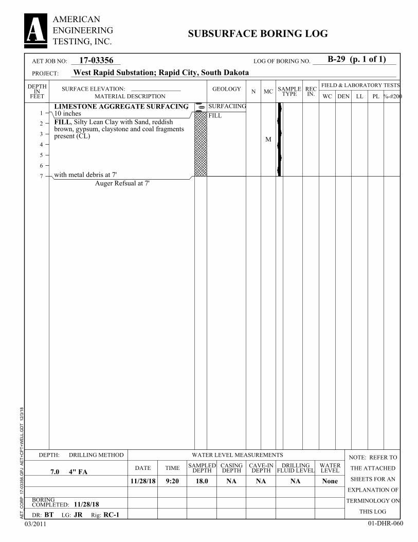
LIMESTONE AGGREGATE SURFACING,10 inchesFILL, Silty Lean Clay with Sand, reddishbrown, gypsum, claystone and coal fragmentspresent (CL)
with metal debris at 7'Auger Refsual at 7'
SURFACIING
FILL
M
BORINGCOMPLETED: 11/28/18
CAVE-INDEPTH
11/28/18 None
CASINGDEPTH
LG:
18.0
DEPTH:
DRILLINGFLUID LEVELDATE
NA4" FA
SURFACE ELEVATION:
RC-1
DRILLING METHOD NOTE: REFER TO
THE ATTACHED
SHEETS FOR AN
EXPLANATION OF
TERMINOLOGY ON
THIS LOGBT
NA
SAMPLEDDEPTH7.0
WATER LEVEL MEASUREMENTS
TIME
DR:
NA
JR
WATERLEVEL
9:20
Rig:
FIELD & LABORATORY TESTSMC
DEN
1
2
3
4
5
6
7
DEPTHIN
FEET WC PLLL %-#200N REC
IN.
03/2011 01-DHR-060
17-03356
AMERICANENGINEERINGTESTING, INC.
SUBSURFACE BORING LOG
SAMPLETYPE
GEOLOGY
West Rapid Substation; Rapid City, South Dakota
MATERIAL DESCRIPTION
AET JOB NO:
PROJECT:
B-29 (p. 1 of 1)LOG OF BORING NO.
AE
T_C
OR
P
17-0
3356
.GP
J A
ET
+C
PT
+W
ELL
.GD
T
12/3
/18

LIMESTONE AGGREGATE SURFACING,12 inchesFILL, Silty Lean Clay with Sand, reddishbrown, gypsum, claystone and coal fragmentspresent (CL)
GYPSUM, white
CLAYSTONE, Silty Lean Clay, red, gypsumlenses present (CL)
Bottom of Boring
SURFACING
FILL
SPEARFISHFORMATION M
BORINGCOMPLETED: 11/28/18
CAVE-INDEPTH
11/28/18 None
CASINGDEPTH
LG:
18.0
DEPTH:
DRILLINGFLUID LEVELDATE
NA4" FA
SURFACE ELEVATION:
RC-1
DRILLING METHOD NOTE: REFER TO
THE ATTACHED
SHEETS FOR AN
EXPLANATION OF
TERMINOLOGY ON
THIS LOGBT
NA
SAMPLEDDEPTH18.0
WATER LEVEL MEASUREMENTS
TIME
DR:
NA
JR
WATERLEVEL
9:45
Rig:
FIELD & LABORATORY TESTSMC
DEN
1
2
3
4
5
6
7
8
9
10
11
12
13
14
15
16
17
18
DEPTHIN
FEET WC PLLL %-#200N REC
IN.
03/2011 01-DHR-060
17-03356
AMERICANENGINEERINGTESTING, INC.
SUBSURFACE BORING LOG
SAMPLETYPE
GEOLOGY
West Rapid Substation; Rapid City, South Dakota
MATERIAL DESCRIPTION
AET JOB NO:
PROJECT:
B-30 (p. 1 of 1)LOG OF BORING NO.
AE
T_C
OR
P
17-0
3356
.GP
J A
ET
+C
PT
+W
ELL
.GD
T
12/3
/18

LIMESTONE AGGREGATE SURFACING,9 inchesFILL, Silty Lean Clay with Sand, reddishbrown, gypsum, claystone and coal fragmentspresent (CL)
CLAYSTONE, Silty Lean Clay, red, gypsumlenses present (CL)
Bottom of Boring
SURFACINGFILL
SPEARFISHFORMATION M
BORINGCOMPLETED: 11/28/18
CAVE-INDEPTH
11/28/18 None
CASINGDEPTH
LG:
18.0
DEPTH:
DRILLINGFLUID LEVELDATE
NA4" FA
SURFACE ELEVATION:
RC-1
DRILLING METHOD NOTE: REFER TO
THE ATTACHED
SHEETS FOR AN
EXPLANATION OF
TERMINOLOGY ON
THIS LOGBT
NA
SAMPLEDDEPTH18.0
WATER LEVEL MEASUREMENTS
TIME
DR:
NA
JR
WATERLEVEL
9:10
Rig:
FIELD & LABORATORY TESTSMC
DEN
1
2
3
4
5
6
7
8
9
10
11
12
13
14
15
16
17
18
DEPTHIN
FEET WC PLLL %-#200N REC
IN.
03/2011 01-DHR-060
17-03356
AMERICANENGINEERINGTESTING, INC.
SUBSURFACE BORING LOG
SAMPLETYPE
GEOLOGY
West Rapid Substation; Rapid City, South Dakota
MATERIAL DESCRIPTION
AET JOB NO:
PROJECT:
B-31 (p. 1 of 1)LOG OF BORING NO.
AE
T_C
OR
P
17-0
3356
.GP
J A
ET
+C
PT
+W
ELL
.GD
T
12/3
/18

LIMESTONE AGGREGATE SURFACING,10 inchesFILL, Silty Lean Clay with Sand, reddishbrown, gypsum, claystone and coal fragmentspresent (CL)
CLAYSTONE, Silty Lean Clay, red, gypsumlenses present (CL)
Bottom of Boring
SURFACIING
FILL
SPEARFISHFORMATION
M
BORINGCOMPLETED: 11/28/18
CAVE-INDEPTH
11/28/18 None
CASINGDEPTH
LG:
18.0
DEPTH:
DRILLINGFLUID LEVELDATE
NA4" FA
SURFACE ELEVATION:
RC-1
DRILLING METHOD NOTE: REFER TO
THE ATTACHED
SHEETS FOR AN
EXPLANATION OF
TERMINOLOGY ON
THIS LOGBT
NA
SAMPLEDDEPTH18.0
WATER LEVEL MEASUREMENTS
TIME
DR:
NA
JR
WATERLEVEL
10:05
Rig:
FIELD & LABORATORY TESTSMC
DEN
1
2
3
4
5
6
7
8
9
10
11
12
13
14
15
16
17
18
DEPTHIN
FEET WC PLLL %-#200N REC
IN.
03/2011 01-DHR-060
17-03356
AMERICANENGINEERINGTESTING, INC.
SUBSURFACE BORING LOG
SAMPLETYPE
GEOLOGY
West Rapid Substation; Rapid City, South Dakota
MATERIAL DESCRIPTION
AET JOB NO:
PROJECT:
B-32 (p. 1 of 1)LOG OF BORING NO.
AE
T_C
OR
P
17-0
3356
.GP
J A
ET
+C
PT
+W
ELL
.GD
T
12/3
/18
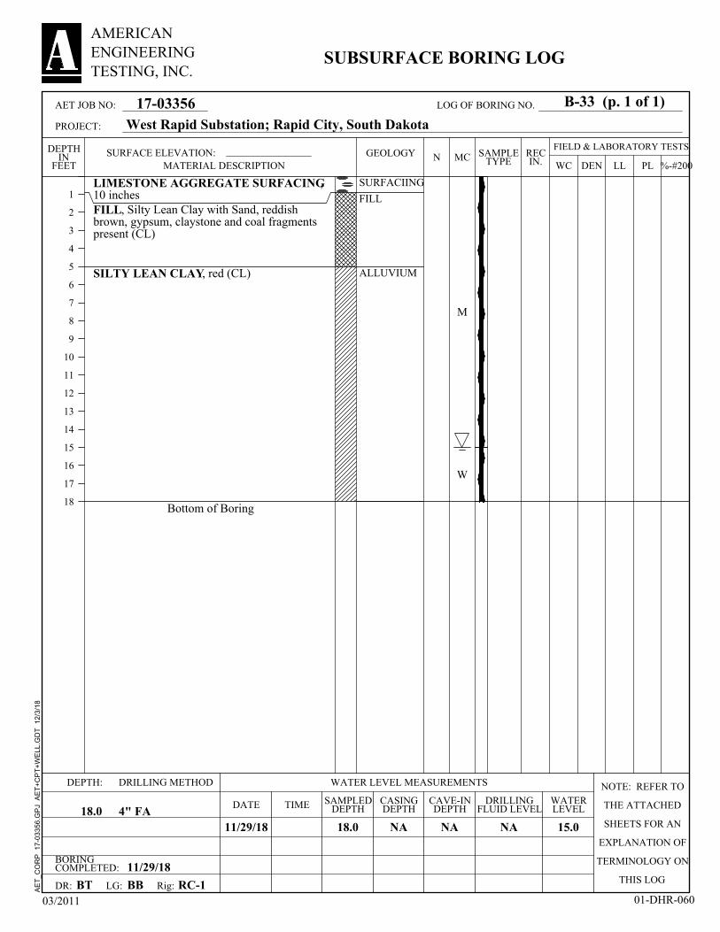
LIMESTONE AGGREGATE SURFACING,10 inchesFILL, Silty Lean Clay with Sand, reddishbrown, gypsum, claystone and coal fragmentspresent (CL)
SILTY LEAN CLAY, red (CL)
Bottom of Boring
SURFACIING
FILL
ALLUVIUM
M
W
BORINGCOMPLETED: 11/29/18
CAVE-INDEPTH
11/29/18 15.0
CASINGDEPTH
LG:
18.0
DEPTH:
DRILLINGFLUID LEVELDATE
NA4" FA
SURFACE ELEVATION:
RC-1
DRILLING METHOD NOTE: REFER TO
THE ATTACHED
SHEETS FOR AN
EXPLANATION OF
TERMINOLOGY ON
THIS LOGBT
NA
SAMPLEDDEPTH18.0
WATER LEVEL MEASUREMENTS
TIME
DR:
NA
BB
WATERLEVEL
Rig:
FIELD & LABORATORY TESTSMC
DEN
1
2
3
4
5
6
7
8
9
10
11
12
13
14
15
16
17
18
DEPTHIN
FEET WC PLLL %-#200N REC
IN.
03/2011 01-DHR-060
17-03356
AMERICANENGINEERINGTESTING, INC.
SUBSURFACE BORING LOG
SAMPLETYPE
GEOLOGY
West Rapid Substation; Rapid City, South Dakota
MATERIAL DESCRIPTION
AET JOB NO:
PROJECT:
B-33 (p. 1 of 1)LOG OF BORING NO.
AE
T_C
OR
P
17-0
3356
.GP
J A
ET
+C
PT
+W
ELL
.GD
T
12/3
/18

LIMESTONE AGGREGATE SURFACING,10 inchesFILL, Silty Lean Clay with Sand, reddishbrown, gypsum, claystone and coal fragmentspresent (CL)
SILTY LEAN CLAY, red (CL)
CLAYSTONE, Silty Lean Clay, red, gypsumlenses present (CL)
Bottom of Boring
SURFACIING
FILL
ALLUVIUM
SPEARFISHFORMATION
M
BORINGCOMPLETED: 11/29/18
CAVE-INDEPTH
11/29/18 None
CASINGDEPTH
LG:
18.0
DEPTH:
DRILLINGFLUID LEVELDATE
NA4" FA
SURFACE ELEVATION:
RC-1
DRILLING METHOD NOTE: REFER TO
THE ATTACHED
SHEETS FOR AN
EXPLANATION OF
TERMINOLOGY ON
THIS LOGBT
NA
SAMPLEDDEPTH18.0
WATER LEVEL MEASUREMENTS
TIME
DR:
NA
BB
WATERLEVEL
Rig:
FIELD & LABORATORY TESTSMC
DEN
1
2
3
4
5
6
7
8
9
10
11
12
13
14
15
16
17
18
DEPTHIN
FEET WC PLLL %-#200N REC
IN.
03/2011 01-DHR-060
17-03356
AMERICANENGINEERINGTESTING, INC.
SUBSURFACE BORING LOG
SAMPLETYPE
GEOLOGY
West Rapid Substation; Rapid City, South Dakota
MATERIAL DESCRIPTION
AET JOB NO:
PROJECT:
B-34 (p. 1 of 1)LOG OF BORING NO.
AE
T_C
OR
P
17-0
3356
.GP
J A
ET
+C
PT
+W
ELL
.GD
T
12/3
/18

LIMESTONE AGGREGATE SURFACING,10 inchesFILL, Silty Lean Clay with Sand, reddishbrown, gypsum, claystone and coal fragmentspresent (CL)
SILTY LEAN CLAY, reddish brown (CL)
Bottom of Boring
SURFACIING
FILL
ALLUVIUM
M
BORINGCOMPLETED: 11/29/18
CAVE-INDEPTH
11/29/18 None
CASINGDEPTH
LG:
18.0
DEPTH:
DRILLINGFLUID LEVELDATE
NA4" FA
SURFACE ELEVATION:
RC-1
DRILLING METHOD NOTE: REFER TO
THE ATTACHED
SHEETS FOR AN
EXPLANATION OF
TERMINOLOGY ON
THIS LOGBT
NA
SAMPLEDDEPTH18.0
WATER LEVEL MEASUREMENTS
TIME
DR:
NA
BB
WATERLEVEL
Rig:
FIELD & LABORATORY TESTSMC
DEN
1
2
3
4
5
6
7
8
9
10
11
12
13
14
15
16
17
18
DEPTHIN
FEET WC PLLL %-#200N REC
IN.
03/2011 01-DHR-060
17-03356
AMERICANENGINEERINGTESTING, INC.
SUBSURFACE BORING LOG
SAMPLETYPE
GEOLOGY
West Rapid Substation; Rapid City, South Dakota
MATERIAL DESCRIPTION
AET JOB NO:
PROJECT:
B-35 (p. 1 of 1)LOG OF BORING NO.
AE
T_C
OR
P
17-0
3356
.GP
J A
ET
+C
PT
+W
ELL
.GD
T
12/3
/18
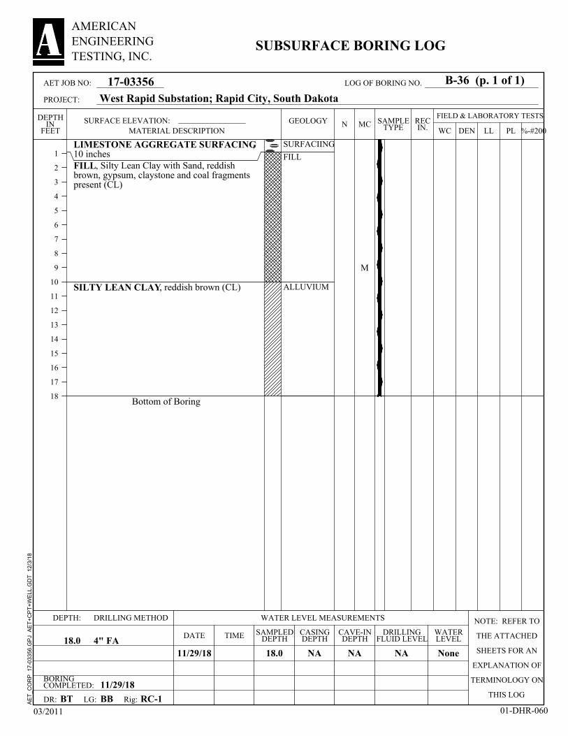
LIMESTONE AGGREGATE SURFACING,10 inchesFILL, Silty Lean Clay with Sand, reddishbrown, gypsum, claystone and coal fragmentspresent (CL)
SILTY LEAN CLAY, reddish brown (CL)
Bottom of Boring
SURFACIING
FILL
ALLUVIUM
M
BORINGCOMPLETED: 11/29/18
CAVE-INDEPTH
11/29/18 None
CASINGDEPTH
LG:
18.0
DEPTH:
DRILLINGFLUID LEVELDATE
NA4" FA
SURFACE ELEVATION:
RC-1
DRILLING METHOD NOTE: REFER TO
THE ATTACHED
SHEETS FOR AN
EXPLANATION OF
TERMINOLOGY ON
THIS LOGBT
NA
SAMPLEDDEPTH18.0
WATER LEVEL MEASUREMENTS
TIME
DR:
NA
BB
WATERLEVEL
Rig:
FIELD & LABORATORY TESTSMC
DEN
1
2
3
4
5
6
7
8
9
10
11
12
13
14
15
16
17
18
DEPTHIN
FEET WC PLLL %-#200N REC
IN.
03/2011 01-DHR-060
17-03356
AMERICANENGINEERINGTESTING, INC.
SUBSURFACE BORING LOG
SAMPLETYPE
GEOLOGY
West Rapid Substation; Rapid City, South Dakota
MATERIAL DESCRIPTION
AET JOB NO:
PROJECT:
B-36 (p. 1 of 1)LOG OF BORING NO.
AE
T_C
OR
P
17-0
3356
.GP
J A
ET
+C
PT
+W
ELL
.GD
T
12/3
/18

LIMESTONE AGGREGATE SURFACING,10 inchesFILL, Silty Lean Clay with Sand, reddishbrown, gypsum, claystone and coal fragmentspresent (CL)
SILTY LEAN CLAY, reddish brown (CL)
Bottom of Boring
SURFACIING
FILL
ALLUVIUM
M
BORINGCOMPLETED: 11/29/18
CAVE-INDEPTH
11/29/18 None
CASINGDEPTH
LG:
18.0
DEPTH:
DRILLINGFLUID LEVELDATE
NA4" FA
SURFACE ELEVATION:
RC-1
DRILLING METHOD NOTE: REFER TO
THE ATTACHED
SHEETS FOR AN
EXPLANATION OF
TERMINOLOGY ON
THIS LOGBT
NA
SAMPLEDDEPTH18.0
WATER LEVEL MEASUREMENTS
TIME
DR:
NA
BB
WATERLEVEL
Rig:
FIELD & LABORATORY TESTSMC
DEN
1
2
3
4
5
6
7
8
9
10
11
12
13
14
15
16
17
18
DEPTHIN
FEET WC PLLL %-#200N REC
IN.
03/2011 01-DHR-060
17-03356
AMERICANENGINEERINGTESTING, INC.
SUBSURFACE BORING LOG
SAMPLETYPE
GEOLOGY
West Rapid Substation; Rapid City, South Dakota
MATERIAL DESCRIPTION
AET JOB NO:
PROJECT:
B-36A (p. 1 of 1)LOG OF BORING NO.
AE
T_C
OR
P
17-0
3356
.GP
J A
ET
+C
PT
+W
ELL
.GD
T
12/3
/18

LIMESTONE AGGREGATE SURFACING,10 inchesFILL, Silty Lean Clay with Sand, reddishbrown, gypsum, claystone and coal fragmentspresent (CL)
SILTY LEAN CLAY, reddish brown (CL)
Bottom of Boring
SURFACIING
FILL
ALLUVIUM
M
BORINGCOMPLETED: 11/29/18
CAVE-INDEPTH
11/29/18 None
CASINGDEPTH
LG:
18.0
DEPTH:
DRILLINGFLUID LEVELDATE
NA4" FA
SURFACE ELEVATION:
RC-1
DRILLING METHOD NOTE: REFER TO
THE ATTACHED
SHEETS FOR AN
EXPLANATION OF
TERMINOLOGY ON
THIS LOGBT
NA
SAMPLEDDEPTH18.0
WATER LEVEL MEASUREMENTS
TIME
DR:
NA
BB
WATERLEVEL
Rig:
FIELD & LABORATORY TESTSMC
DEN
1
2
3
4
5
6
7
8
9
10
11
12
13
14
15
16
17
18
DEPTHIN
FEET WC PLLL %-#200N REC
IN.
03/2011 01-DHR-060
17-03356
AMERICANENGINEERINGTESTING, INC.
SUBSURFACE BORING LOG
SAMPLETYPE
GEOLOGY
West Rapid Substation; Rapid City, South Dakota
MATERIAL DESCRIPTION
AET JOB NO:
PROJECT:
B-36B (p. 1 of 1)LOG OF BORING NO.
AE
T_C
OR
P
17-0
3356
.GP
J A
ET
+C
PT
+W
ELL
.GD
T
12/3
/18

LIMESTONE AGGREGATE SURFACING,10 inchesFILL, Silty Lean Clay with Sand, reddishbrown, gypsum, claystone and coal fragmentspresent (CL)
SILTY LEAN CLAY, reddish brown (CL)
Bottom of Boring
SURFACIING
FILL
ALLUVIUM
M
BORINGCOMPLETED: 11/29/18
CAVE-INDEPTH
11/29/18 None
CASINGDEPTH
LG:
18.0
DEPTH:
DRILLINGFLUID LEVELDATE
NA4" FA
SURFACE ELEVATION:
RC-1
DRILLING METHOD NOTE: REFER TO
THE ATTACHED
SHEETS FOR AN
EXPLANATION OF
TERMINOLOGY ON
THIS LOGBT
NA
SAMPLEDDEPTH18.0
WATER LEVEL MEASUREMENTS
TIME
DR:
NA
BB
WATERLEVEL
Rig:
FIELD & LABORATORY TESTSMC
DEN
1
2
3
4
5
6
7
8
9
10
11
12
13
14
15
16
17
18
DEPTHIN
FEET WC PLLL %-#200N REC
IN.
03/2011 01-DHR-060
17-03356
AMERICANENGINEERINGTESTING, INC.
SUBSURFACE BORING LOG
SAMPLETYPE
GEOLOGY
West Rapid Substation; Rapid City, South Dakota
MATERIAL DESCRIPTION
AET JOB NO:
PROJECT:
B-36C (p. 1 of 1)LOG OF BORING NO.
AE
T_C
OR
P
17-0
3356
.GP
J A
ET
+C
PT
+W
ELL
.GD
T
12/3
/18

LIMESTONE AGGREGATE SURFACING,10 inchesFILL, Silty Lean Clay with Sand, reddishbrown, gypsum, claystone and coal fragmentspresent (CL)
SILTY LEAN CLAY, reddish brown (CL)
Bottom of Boring
SURFACIING
FILL
ALLUVIUM
M
BORINGCOMPLETED: 11/29/18
CAVE-INDEPTH
11/29/18 None
CASINGDEPTH
LG:
18.0
DEPTH:
DRILLINGFLUID LEVELDATE
NA4" FA
SURFACE ELEVATION:
RC-1
DRILLING METHOD NOTE: REFER TO
THE ATTACHED
SHEETS FOR AN
EXPLANATION OF
TERMINOLOGY ON
THIS LOGBT
NA
SAMPLEDDEPTH18.0
WATER LEVEL MEASUREMENTS
TIME
DR:
NA
BB
WATERLEVEL
Rig:
FIELD & LABORATORY TESTSMC
DEN
1
2
3
4
5
6
7
8
9
10
11
12
13
14
15
16
17
18
DEPTHIN
FEET WC PLLL %-#200N REC
IN.
03/2011 01-DHR-060
17-03356
AMERICANENGINEERINGTESTING, INC.
SUBSURFACE BORING LOG
SAMPLETYPE
GEOLOGY
West Rapid Substation; Rapid City, South Dakota
MATERIAL DESCRIPTION
AET JOB NO:
PROJECT:
B-36D (p. 1 of 1)LOG OF BORING NO.
AE
T_C
OR
P
17-0
3356
.GP
J A
ET
+C
PT
+W
ELL
.GD
T
12/3
/18

LIMESTONE AGGREGATE SURFACING,10 inchesFILL, Silty Lean Clay with Sand, reddishbrown, gypsum, claystone and coal fragmentspresent (CL)
SILTY LEAN CLAY, reddish brown (CL)
Bottom of Boring
SURFACIING
FILL
ALLUVIUM
M
BORINGCOMPLETED: 11/29/18
CAVE-INDEPTH
11/29/18 None
CASINGDEPTH
LG:
18.0
DEPTH:
DRILLINGFLUID LEVELDATE
NA4" FA
SURFACE ELEVATION:
RC-1
DRILLING METHOD NOTE: REFER TO
THE ATTACHED
SHEETS FOR AN
EXPLANATION OF
TERMINOLOGY ON
THIS LOGBT
NA
SAMPLEDDEPTH18.0
WATER LEVEL MEASUREMENTS
TIME
DR:
NA
BB
WATERLEVEL
Rig:
FIELD & LABORATORY TESTSMC
DEN
1
2
3
4
5
6
7
8
9
10
11
12
13
14
15
16
17
18
DEPTHIN
FEET WC PLLL %-#200N REC
IN.
03/2011 01-DHR-060
17-03356
AMERICANENGINEERINGTESTING, INC.
SUBSURFACE BORING LOG
SAMPLETYPE
GEOLOGY
West Rapid Substation; Rapid City, South Dakota
MATERIAL DESCRIPTION
AET JOB NO:
PROJECT:
B-37 (p. 1 of 1)LOG OF BORING NO.
AE
T_C
OR
P
17-0
3356
.GP
J A
ET
+C
PT
+W
ELL
.GD
T
12/3
/18

LIMESTONE AGGREGATE SURFACING,10 inchesFILL, Silty Lean Clay with Sand, reddishbrown, gypsum, claystone and coal fragmentspresent (CL)
SILTY LEAN CLAY, reddish brown (CL)
Bottom of Boring
SURFACIING
FILL
ALLUVIUM
M
BORINGCOMPLETED: 11/29/18
CAVE-INDEPTH
11/29/18 None
CASINGDEPTH
LG:
18.0
DEPTH:
DRILLINGFLUID LEVELDATE
NA4" FA
SURFACE ELEVATION:
RC-1
DRILLING METHOD NOTE: REFER TO
THE ATTACHED
SHEETS FOR AN
EXPLANATION OF
TERMINOLOGY ON
THIS LOGBT
NA
SAMPLEDDEPTH18.0
WATER LEVEL MEASUREMENTS
TIME
DR:
NA
BB
WATERLEVEL
Rig:
FIELD & LABORATORY TESTSMC
DEN
1
2
3
4
5
6
7
8
9
10
11
12
13
14
15
16
17
18
DEPTHIN
FEET WC PLLL %-#200N REC
IN.
03/2011 01-DHR-060
17-03356
AMERICANENGINEERINGTESTING, INC.
SUBSURFACE BORING LOG
SAMPLETYPE
GEOLOGY
West Rapid Substation; Rapid City, South Dakota
MATERIAL DESCRIPTION
AET JOB NO:
PROJECT:
B-37A (p. 1 of 1)LOG OF BORING NO.
AE
T_C
OR
P
17-0
3356
.GP
J A
ET
+C
PT
+W
ELL
.GD
T
12/3
/18

LIMESTONE AGGREGATE SURFACING,10 inchesFILL, Silty Lean Clay with Sand, reddishbrown, gypsum, claystone and coal fragmentspresent (CL)
SILTY LEAN CLAY, reddish brown (CL)
Bottom of Boring
SURFACIING
FILL
ALLUVIUM
M
BORINGCOMPLETED: 11/29/18
CAVE-INDEPTH
11/29/18 None
CASINGDEPTH
LG:
18.0
DEPTH:
DRILLINGFLUID LEVELDATE
NA4" FA
SURFACE ELEVATION:
RC-1
DRILLING METHOD NOTE: REFER TO
THE ATTACHED
SHEETS FOR AN
EXPLANATION OF
TERMINOLOGY ON
THIS LOGBT
NA
SAMPLEDDEPTH18.0
WATER LEVEL MEASUREMENTS
TIME
DR:
NA
BB
WATERLEVEL
Rig:
FIELD & LABORATORY TESTSMC
DEN
1
2
3
4
5
6
7
8
9
10
11
12
13
14
15
16
17
18
DEPTHIN
FEET WC PLLL %-#200N REC
IN.
03/2011 01-DHR-060
17-03356
AMERICANENGINEERINGTESTING, INC.
SUBSURFACE BORING LOG
SAMPLETYPE
GEOLOGY
West Rapid Substation; Rapid City, South Dakota
MATERIAL DESCRIPTION
AET JOB NO:
PROJECT:
B-37B (p. 1 of 1)LOG OF BORING NO.
AE
T_C
OR
P
17-0
3356
.GP
J A
ET
+C
PT
+W
ELL
.GD
T
12/3
/18

LIMESTONE AGGREGATE SURFACING,10 inchesFILL, Silty Lean Clay with Sand, reddishbrown, gypsum, claystone and coal fragmentspresent (CL)
SILTY LEAN CLAY, reddish brown (CL)
Bottom of Boring
SURFACIING
FILL
ALLUVIUM
M
BORINGCOMPLETED: 11/29/18
CAVE-INDEPTH
11/29/18 None
CASINGDEPTH
LG:
18.0
DEPTH:
DRILLINGFLUID LEVELDATE
NA4" FA
SURFACE ELEVATION:
RC-1
DRILLING METHOD NOTE: REFER TO
THE ATTACHED
SHEETS FOR AN
EXPLANATION OF
TERMINOLOGY ON
THIS LOGBT
NA
SAMPLEDDEPTH18.0
WATER LEVEL MEASUREMENTS
TIME
DR:
NA
BB
WATERLEVEL
Rig:
FIELD & LABORATORY TESTSMC
DEN
1
2
3
4
5
6
7
8
9
10
11
12
13
14
15
16
17
18
DEPTHIN
FEET WC PLLL %-#200N REC
IN.
03/2011 01-DHR-060
17-03356
AMERICANENGINEERINGTESTING, INC.
SUBSURFACE BORING LOG
SAMPLETYPE
GEOLOGY
West Rapid Substation; Rapid City, South Dakota
MATERIAL DESCRIPTION
AET JOB NO:
PROJECT:
B-37C (p. 1 of 1)LOG OF BORING NO.
AE
T_C
OR
P
17-0
3356
.GP
J A
ET
+C
PT
+W
ELL
.GD
T
12/3
/18

LIMESTONE AGGREGATE SURFACING,10 inchesFILL, Silty Lean Clay with Sand, reddishbrown, gypsum, claystone and coal fragmentspresent (CL)
SILTY LEAN CLAY, reddish brown (CL)
Bottom of Boring
SURFACIING
FILL
ALLUVIUM
M
BORINGCOMPLETED: 11/29/18
CAVE-INDEPTH
11/29/18 None
CASINGDEPTH
LG:
18.0
DEPTH:
DRILLINGFLUID LEVELDATE
NA4" FA
SURFACE ELEVATION:
RC-1
DRILLING METHOD NOTE: REFER TO
THE ATTACHED
SHEETS FOR AN
EXPLANATION OF
TERMINOLOGY ON
THIS LOGBT
NA
SAMPLEDDEPTH18.0
WATER LEVEL MEASUREMENTS
TIME
DR:
NA
BB
WATERLEVEL
Rig:
FIELD & LABORATORY TESTSMC
DEN
1
2
3
4
5
6
7
8
9
10
11
12
13
14
15
16
17
18
DEPTHIN
FEET WC PLLL %-#200N REC
IN.
03/2011 01-DHR-060
17-03356
AMERICANENGINEERINGTESTING, INC.
SUBSURFACE BORING LOG
SAMPLETYPE
GEOLOGY
West Rapid Substation; Rapid City, South Dakota
MATERIAL DESCRIPTION
AET JOB NO:
PROJECT:
B-37D (p. 1 of 1)LOG OF BORING NO.
AE
T_C
OR
P
17-0
3356
.GP
J A
ET
+C
PT
+W
ELL
.GD
T
12/3
/18

LIMESTONE AGGREGATE SURFACING,10 inchesFILL, Silty Lean Clay with Sand, reddishbrown, gypsum, claystone and coal fragmentspresent (CL)
SILTY LEAN CLAY, reddish brown (CL)
CLAYSTONE, Silty Lean Clay, red, gypsumlenses present (CL)
Bottom of Boring
SURFACIING
FILL
ALLUVIUM
SPEARFISHFORMATION
M
W
BORINGCOMPLETED: 11/29/18
CAVE-INDEPTH
11/29/18 17.0
CASINGDEPTH
LG:
18.0
DEPTH:
DRILLINGFLUID LEVELDATE
NA4" FA
SURFACE ELEVATION:
RC-1
DRILLING METHOD NOTE: REFER TO
THE ATTACHED
SHEETS FOR AN
EXPLANATION OF
TERMINOLOGY ON
THIS LOGBT
NA
SAMPLEDDEPTH18.0
WATER LEVEL MEASUREMENTS
TIME
DR:
NA
BB
WATERLEVEL
Rig:
FIELD & LABORATORY TESTSMC
DEN
1
2
3
4
5
6
7
8
9
10
11
12
13
14
15
16
17
18
DEPTHIN
FEET WC PLLL %-#200N REC
IN.
03/2011 01-DHR-060
17-03356
AMERICANENGINEERINGTESTING, INC.
SUBSURFACE BORING LOG
SAMPLETYPE
GEOLOGY
West Rapid Substation; Rapid City, South Dakota
MATERIAL DESCRIPTION
AET JOB NO:
PROJECT:
B-38 (p. 1 of 1)LOG OF BORING NO.
AE
T_C
OR
P
17-0
3356
.GP
J A
ET
+C
PT
+W
ELL
.GD
T
12/3
/18

LIMESTONE AGGREGATE SURFACING,10 inchesFILL, Silty Lean Clay with Sand, reddishbrown, gypsum, claystone and coal fragmentspresent (CL)
with possible gypsum boulder present
SILTY LEAN CLAY, reddish brown (CL)
with strong hydrocarbon odor and discolorationCLAYSTONE, Silty Lean Clay, red, gypsumlenses present (CL)
Bottom of Boring
SURFACIING
FILL
ALLUVIUM
SPEARFISHFORMATION
M
W
BORINGCOMPLETED: 11/29/18
CAVE-INDEPTH
11/29/18 16.0
CASINGDEPTH
LG:
18.0
DEPTH:
DRILLINGFLUID LEVELDATE
NA4" FA
SURFACE ELEVATION:
RC-1
DRILLING METHOD NOTE: REFER TO
THE ATTACHED
SHEETS FOR AN
EXPLANATION OF
TERMINOLOGY ON
THIS LOGBT
NA
SAMPLEDDEPTH18.0
WATER LEVEL MEASUREMENTS
TIME
DR:
NA
BB
WATERLEVEL
Rig:
FIELD & LABORATORY TESTSMC
DEN
1
2
3
4
5
6
7
8
9
10
11
12
13
14
15
16
17
18
DEPTHIN
FEET WC PLLL %-#200N REC
IN.
03/2011 01-DHR-060
17-03356
AMERICANENGINEERINGTESTING, INC.
SUBSURFACE BORING LOG
SAMPLETYPE
GEOLOGY
West Rapid Substation; Rapid City, South Dakota
MATERIAL DESCRIPTION
AET JOB NO:
PROJECT:
B-39 (p. 1 of 1)LOG OF BORING NO.
AE
T_C
OR
P
17-0
3356
.GP
J A
ET
+C
PT
+W
ELL
.GD
T
12/3
/18

LIMESTONE AGGREGATE SURFACING,10 inchesFILL, Silty Lean Clay with Sand, reddishbrown, gypsum, claystone and coal fragmentspresent (CL)
SILTY LEAN CLAY, reddish brown (CL)
CLAYSTONE, Silty Lean Clay, red, gypsumlenses present (CL)
Bottom of Boring
SURFACIING
FILL
ALLUVIUM
SPEARFISHFORMATION
M
W
BORINGCOMPLETED: 11/29/18
CAVE-INDEPTH
11/29/18 15.5
CASINGDEPTH
LG:
18.0
DEPTH:
DRILLINGFLUID LEVELDATE
NA4" FA
SURFACE ELEVATION:
RC-1
DRILLING METHOD NOTE: REFER TO
THE ATTACHED
SHEETS FOR AN
EXPLANATION OF
TERMINOLOGY ON
THIS LOGBT
NA
SAMPLEDDEPTH18.0
WATER LEVEL MEASUREMENTS
TIME
DR:
NA
BB
WATERLEVEL
Rig:
FIELD & LABORATORY TESTSMC
DEN
1
2
3
4
5
6
7
8
9
10
11
12
13
14
15
16
17
18
DEPTHIN
FEET WC PLLL %-#200N REC
IN.
03/2011 01-DHR-060
17-03356
AMERICANENGINEERINGTESTING, INC.
SUBSURFACE BORING LOG
SAMPLETYPE
GEOLOGY
West Rapid Substation; Rapid City, South Dakota
MATERIAL DESCRIPTION
AET JOB NO:
PROJECT:
B-40 (p. 1 of 1)LOG OF BORING NO.
AE
T_C
OR
P
17-0
3356
.GP
J A
ET
+C
PT
+W
ELL
.GD
T
12/3
/18

LIMESTONE AGGREGATE SURFACING,10 inchesFILL, Silty Lean Clay with Sand, reddishbrown, gypsum, claystone and coal fragmentspresent (CL)
SILTY LEAN CLAY, reddish brown (CL)
CLAYSTONE, Silty Lean Clay, red, gypsumlenses present (CL)
Bottom of Boring
SURFACIING
FILL
ALLUVIUM
SPEARFISHFORMATION
M
W
BORINGCOMPLETED: 11/29/18
CAVE-INDEPTH
11/29/18 16.0
CASINGDEPTH
LG:
18.0
DEPTH:
DRILLINGFLUID LEVELDATE
NA4" FA
SURFACE ELEVATION:
RC-1
DRILLING METHOD NOTE: REFER TO
THE ATTACHED
SHEETS FOR AN
EXPLANATION OF
TERMINOLOGY ON
THIS LOGBT
NA
SAMPLEDDEPTH18.0
WATER LEVEL MEASUREMENTS
TIME
DR:
NA
BB
WATERLEVEL
Rig:
FIELD & LABORATORY TESTSMC
DEN
1
2
3
4
5
6
7
8
9
10
11
12
13
14
15
16
17
18
DEPTHIN
FEET WC PLLL %-#200N REC
IN.
03/2011 01-DHR-060
17-03356
AMERICANENGINEERINGTESTING, INC.
SUBSURFACE BORING LOG
SAMPLETYPE
GEOLOGY
West Rapid Substation; Rapid City, South Dakota
MATERIAL DESCRIPTION
AET JOB NO:
PROJECT:
B-41 (p. 1 of 1)LOG OF BORING NO.
AE
T_C
OR
P
17-0
3356
.GP
J A
ET
+C
PT
+W
ELL
.GD
T
12/3
/18

LIMESTONE AGGREGATE SURFACING,10 inchesFILL, Silty Lean Clay with Sand, reddishbrown, gypsum, claystone and coal fragmentspresent (CL)
SILTY LEAN CLAY, reddish brown (CL)
CLAYSTONE, Silty Lean Clay, red, gypsumlenses present (CL)
Bottom of Boring
SURFACIING
FILL
ALLUVIUM
SPEARFISHFORMATION
M
W
BORINGCOMPLETED: 11/29/18
CAVE-INDEPTH
11/29/18 17.0
CASINGDEPTH
LG:
18.0
DEPTH:
DRILLINGFLUID LEVELDATE
NA4" FA
SURFACE ELEVATION:
RC-1
DRILLING METHOD NOTE: REFER TO
THE ATTACHED
SHEETS FOR AN
EXPLANATION OF
TERMINOLOGY ON
THIS LOGBT
NA
SAMPLEDDEPTH18.0
WATER LEVEL MEASUREMENTS
TIME
DR:
NA
BB
WATERLEVEL
Rig:
FIELD & LABORATORY TESTSMC
DEN
1
2
3
4
5
6
7
8
9
10
11
12
13
14
15
16
17
18
DEPTHIN
FEET WC PLLL %-#200N REC
IN.
03/2011 01-DHR-060
17-03356
AMERICANENGINEERINGTESTING, INC.
SUBSURFACE BORING LOG
SAMPLETYPE
GEOLOGY
West Rapid Substation; Rapid City, South Dakota
MATERIAL DESCRIPTION
AET JOB NO:
PROJECT:
B-42 (p. 1 of 1)LOG OF BORING NO.
AE
T_C
OR
P
17-0
3356
.GP
J A
ET
+C
PT
+W
ELL
.GD
T
12/3
/18
CONSULTANTS • GEOTECHNICAL• MATERIALS• ENVIRONMENTAL• FORENSICS
www.amengtest.com
REPORT OF GEOTECHNICAL EXPLORATION AND REVIEW
WEST RAPID SUBSTATION TRANSMISSION LINE POLES RAPID CITY, SOUTH DAKOTA
AET No. 17-03356
Date: January 16, 2019
Prepared for:
Black Hills Energy 7001 Mt. Rushmore Road Rapid City, South Dakota 57702

1745 Samco Road | Rapid City, SD 57702 Phone (605) 388-0029 | Toll Free (800) 972-6364 | Fax (605) 388-0064 | www.amengtest.com | AA/EEO
This document shall not be reproduced, except in full, without written approval from American Engineering Testing, Inc.
January 16, 2019 Black Hills Energy 7001 Mt. Rushmore Road Rapid City, South Dakota 57702 Attn: Mr. Ron Williams, PE RE: Geotechnical Exploration and Review West Rapid Substation Transmission Line Poles Rapid City, South Dakota Report No.17-03356 Dear Ron, American Engineering Testing, Inc. (AET) is pleased to present the results of our subsurface exploration program and geotechnical engineering review for the proposed transmission line poles to be constructed as part of the West Rapid Substation project, in Rapid City, South Dakota. These services were performed in general accordance with our proposal dated December 5, 2018 and the signed Statement of Services No. 38863, Change Order No. 4, dated December 17, 2018. We are submitting one (1) electronic copy of the report to you. Within the limitations of scope, budget, and schedule, our services have been conducted according to generally accepted geotechnical engineering practices at this time and location. Other than this, no warranty, either expressed or implied, is intended. Important information regarding risk management and proper use of this report is given in the Appendix entitled “Geotechnical Report Limitations and Guidelines for Use”. Please contact our office if you have any questions about the report. We can also be contacted to arrange the observation and testing services during construction of the project. Sincerely, American Engineering Testing, Inc. Walt Feeger, P.E. Senior Geotechnical Engineer Phone: (605) 388-0029 [email protected]
Page i
CONSULTANTS · GEOTECHNICAL · MATERIALS · ENVIRONMENTAL
A AMERICANENGINEERINGTESTING, INC.

Report of Geotechnical Exploration and Review West Rapid Substation Transmission Line Poles – Rapid City, South Dakota AMERICAN January 16, 2019 ENGINEERING Report No. 17-03356 TESTING, INC.
Page ii Copyright 2019 American Engineering Testing, Inc. All Rights Reserved
Unauthorized use or copying of this document is strictly prohibited by anyone other than the client for the specific project.
SIGNATURE PAGE
Prepared for: Prepared by: Black Hills Energy American Engineering Testing, Inc. 7001 Mt. Rushmore Road 1745 Samco Road Rapid City, South Dakota 57701 Rapid City, South Dakota 57702 Attn: Mr. Ron Williams, PE Report Authored By: Peer Review Conducted By: Walt Feeger, P.E. Robert Temme, P.E. Senior Geotechnical Engineer Vice President – Western Region

Report of Geotechnical Exploration and Review West Rapid Substation Transmission Line Poles – Rapid City, South Dakota AMERICAN January 16, 2019 ENGINEERING Report No. 17-03356 TESTING, INC.
TABLE OF CONTENTS
Transmittal Letter............................................................................................................................. i Signature Page ................................................................................................................................ ii TABLE OF CONTENTS ............................................................................................................... iii 1.0 INTRODUCTION .................................................................................................................... 1 2.0 SCOPE OF SERVICES ............................................................................................................ 1 3.0 PROJECT INFORMATION ..................................................................................................... 1 4.0 SUBSURFACE EXPLORATION AND TESTING ................................................................ 2
4.1 Field Exploration Program .................................................................................................... 2 4.2 Laboratory Testing ................................................................................................................ 3
5.0 SITE CONDITIONS ................................................................................................................. 3 5.1 Surface Observations ............................................................................................................. 3 5.2 Subsurface Soils/Geology ....................................................................................................... 3 5.3 Groundwater .......................................................................................................................... 4
6.0 RECOMMENDATIONS .......................................................................................................... 5 6.1 Discussion .............................................................................................................................. 5 6.2 Drilled Pier Foundation Recommendations .......................................................................... 5
7.0 LIMITATIONS ....................................................................................................................... 12 APPENDIX A - Geotechnical Field Exploration and Testing Boring Log Notes Unified Soil Classification System Site Location Map Boring Location Map Subsurface Boring Logs Unconfined Compression Test Results Swell-Consolidation Test Results APPENDIX B - Geotechnical Report Limitations and Guidelines for Use
Page iii

Report of Geotechnical Exploration and Review West Rapid Substation Transmission Line Poles – Rapid City, South Dakota AMERICAN January 16, 2019 ENGINEERING Report No. 17-03356 TESTING, INC.
PAGE 1 OF 12
1.0 INTRODUCTION
We understand a new transmission line will be constructed as part of the proposed West Rapid
Substation project in Rapid City, South Dakota. Please refer to the Site Location Map in Appendix
A for the approximate location of the sites. To assist with the planning and design, American
Engineering Testing, Inc. (AET) has been authorized to conduct a subsurface exploration program
at the locations of the transmission poles, conduct soil laboratory testing, and perform a
geotechnical engineering review for the project. This report presents the results of the above
services, and provides our engineering recommendations based on this data.
2.0 SCOPE OF SERVICES
AET's services were performed in general accordance with our proposal dated December 5, 2018.
The authorized scope consists of the following:
• Eight (8) standard penetration test (SPT) borings at the proposed transmission pole locations to depths of about 50 feet below existing grade.
• Soil laboratory testing. • Geotechnical engineering analysis based on the gained data and preparation of this
report. These services are intended for geotechnical purposes only. The scope is not intended to explore
for the presence or extent of environmental contamination.
3.0 PROJECT INFORMATION
AET recently completed the geotechnical services for the proposed West Rapid Substation project,
and submitted our findings and recommendations in our Report No. 17-03356, dated May 31,
2018. We understand that, as part of the new substation, a transmission line will also be required.
Furthermore, we understand these types of pole structures are typically placed on reinforced
concrete drilled piers (caissons). The following loading information at the respective boring
locations was provided by HDR Engineering, Inc.
• B-1 Moment: 13,000 ft-k Shear Force: 185 kips Vertical Force: 85 kips
• B-3 Moment: 18,900 ft-k Shear Force: 205 kips Vertical Force: 125 kips
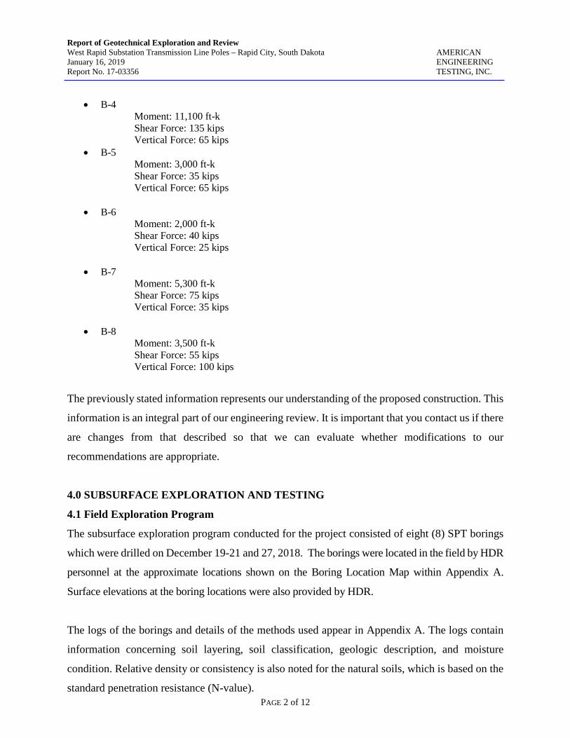
Report of Geotechnical Exploration and Review West Rapid Substation Transmission Line Poles – Rapid City, South Dakota AMERICAN January 16, 2019 ENGINEERING Report No. 17-03356 TESTING, INC.
PAGE 2 of 12
• B-4
Moment: 11,100 ft-k Shear Force: 135 kips Vertical Force: 65 kips
• B-5 Moment: 3,000 ft-k Shear Force: 35 kips Vertical Force: 65 kips
• B-6 Moment: 2,000 ft-k Shear Force: 40 kips Vertical Force: 25 kips
• B-7 Moment: 5,300 ft-k Shear Force: 75 kips Vertical Force: 35 kips
• B-8 Moment: 3,500 ft-k Shear Force: 55 kips Vertical Force: 100 kips
The previously stated information represents our understanding of the proposed construction. This
information is an integral part of our engineering review. It is important that you contact us if there
are changes from that described so that we can evaluate whether modifications to our
recommendations are appropriate.
4.0 SUBSURFACE EXPLORATION AND TESTING
4.1 Field Exploration Program
The subsurface exploration program conducted for the project consisted of eight (8) SPT borings
which were drilled on December 19-21 and 27, 2018. The borings were located in the field by HDR
personnel at the approximate locations shown on the Boring Location Map within Appendix A.
Surface elevations at the boring locations were also provided by HDR.
The logs of the borings and details of the methods used appear in Appendix A. The logs contain
information concerning soil layering, soil classification, geologic description, and moisture
condition. Relative density or consistency is also noted for the natural soils, which is based on the
standard penetration resistance (N-value).

Report of Geotechnical Exploration and Review West Rapid Substation Transmission Line Poles – Rapid City, South Dakota AMERICAN January 16, 2019 ENGINEERING Report No. 17-03356 TESTING, INC.
PAGE 3 of 12
4.2 Laboratory Testing
The laboratory test program included water content, dry density, unconfined compression,
swell-consolidation. The laboratory test results appear in Appendix A on the individual boring
logs adjacent to the samples upon which they were performed with the exception of the
unconfined compression and swell-consolidation tests, which can be found on separate sheets
within Appendix A of this report.
5.0 SITE CONDITIONS
5.1 Surface Observations
At the time of our field work, the areas surrounding the proposed transmission pole locations
consisted of the existing Black Hills Energy Service Center (Borings B-3 through B-8) facility as
well as vacant tracts of property around Borings B-1 and B-2, which were vegetated with native
grasses and weeds.
5.2 Subsurface Soils/Geology
Underlying a thin layer of gravel surfacing or topsoil, the following subsurface conditions were
encountered at the boring locations:
Boring B-1: Approximately 19½ feet of alluvium comprised of medium dense silty sands, firm to hard sandy lean clays, and dense to very dense sandy gravels overlying shale bedrock, associated with the Sundance Formation, which extended to the total depth explored. Boring B-2: Approximately 7 feet of alluvium comprised of very stiff fat clay and hard silty lean clay overlying stiff to very stiff weathered to hard, competent shale bedrock, associated with the Spearfish Formation, which extended to the total depth explored. Boring B-3: Approximately 9½ feet of alluvium comprised of hard silty lean clays and very dense sandy gravels overlying hard shale of the Sundance Formation, over gypsum and hard siltstone bedrock of the Gypsum Spring Formation, which extended to the total depth explored. Boring B-4: Near surface hard shale of the Sundance Formation was encountered overlying gypsum, and interbedded hard siltstone and shale bedrock of the Gypsum Spring Formation, which extended to the total depth explored.

Report of Geotechnical Exploration and Review West Rapid Substation Transmission Line Poles – Rapid City, South Dakota AMERICAN January 16, 2019 ENGINEERING Report No. 17-03356 TESTING, INC.
PAGE 4 of 12
Boring B-5: Approximately 14 feet of lean to fat clay fill was encountered overlying about 3½ feet of firm sandy lean clay alluvium. The alluvium in underlain by hard weathered to competent shale of the Spearfish Formation, which extended to the terminal boring depth. Boring B-6: About 9 feet of silty lean clay fill overlying approximately 13½ feet of alluvium comprised of soft to firm lean clays. The alluvium is underlain by stiff to hard weathered to competent shale, associated with the Spearfish Formation. Boring B-7: Near surface stiff to hard weathered to competent shale bedrock, associated with the Spearfish Formation was encountered to the total depth explored. Approximately 10 feet of gypsum was encountered at a depth of about 25 feet below grade. Boring B-8: Approximately 4½ feet of lean clay fill was encountered overlying about 9½ feet of alluvium comprised of very stiff fat clay and very stiff lean clay. The alluvium is underlain by hard weathered to competent shale bedrock of the Spearfish Formation. Conditions encountered at each boring location are indicated on the individual boring logs in
Appendix A of this report.
5.3 Groundwater
At the time of our field work, measurable groundwater was encountered at the approximate noted
depths in the following borings:
B-1: 7½ feet below grade (BG) B-2: 15 feet BG B-5: 8 feet BG B-6: 11 feet BG B-7: 20 feet BG
The presence or lack of groundwater noted at the boring locations should not be taken as an accurate
representation of the actual groundwater levels. Groundwater level fluctuations occur due to seasonal
variations in the amount of precipitation, surface drainage, local irrigation practices, level of water in
Rapid Creek, and other factors not evident at the time the borings were performed. Due to the
relatively low permeability of the clay/silt soils and shale/siltstone bedrock encountered in the
borings, a relatively long period of time may be needed for a groundwater level to develop and/or
stabilize in the borings.
Report of Geotechnical Exploration and Review West Rapid Substation Transmission Line Poles – Rapid City, South Dakota AMERICAN January 16, 2019 ENGINEERING Report No. 17-03356 TESTING, INC.
PAGE 5 of 12
The possibility of encountering groundwater and associated fluctuations in groundwater levels should
be considered when developing the design and construction plans for the project.
6.0 RECOMMENDATIONS
6.1 Discussion
Our recommendations in the following sections are based on our understanding of the project
details at this time. The geotechnical engineer should be allowed to review the final project plans
to verify the following recommendations remain applicable for construction.
Based on the field and laboratory data, it is our opinion drilled pier foundations can be used to
support the proposed transmission line poles. For drilled piers, loadings should provide a
theoretical safety factor of 2 or more with total and differential movements not exceeding 1-inch
and 1/2-inch, respectively.
Additionally, it should be noted that gypsum is a common geologic feature found in the Spearfish
Formation derived soils at this site. Once exposed, gypsum material can degrade which could
cause future movement related distress to the structures, especially if water is introduced to the
gypsum matrix. Therefore, drilled pier foundations should not terminate (end bear) on gypsum.
6.2 Drilled Pier Foundation Recommendations
Based on the results of the borings, laboratory testing, and our analysis, we have developed the
following design parameters. We recommend all drilled piers bear at least 5 feet into the noted
bedrock stratum with the recommended minimum length.
Boring B-1
Soil Type Allowable Skin Friction (psf)
Allowable End Bearing Pressure (psf)
Frost Zone (0 – 5’) Ignore Ignore
Lean Clay Alluvium 300 na
Gravel Alluvium 200 na
Shale Bedrock 1,000 20,000 (minimum pier length – 25’)

Report of Geotechnical Exploration and Review West Rapid Substation Transmission Line Poles – Rapid City, South Dakota AMERICAN January 16, 2019 ENGINEERING Report No. 17-03356 TESTING, INC.
PAGE 6 of 12
Boring B-2
Soil Type Allowable Skin Friction (psf)
Allowable End Bearing Pressure (psf)
Frost Zone (0 – 5’) Ignore Ignore
Lean Clay Alluvium 300 na
W. Shale Bedrock 300 na
Shale Bedrock 1,000 20,000 (minimum pier Length – 28’)
Boring B-3
Soil Type Allowable Skin Friction (psf)
Allowable End Bearing Pressure (psf)
Frost Zone (0 – 5’) Ignore Ignore
Lean Clay Alluvium 300 na
Gravel Alluvium 200 na
Shale Bedrock 1,000 20,000
(minimum pier length – 15’) Do not end bear in gypsum formation
Siltstone Bedrock 750 20,000
Boring B-4
Soil Type Allowable Skin Friction (psf)
Allowable End Bearing Pressure (psf)
Frost Zone (0 – 5’) Ignore Ignore
Gypsum na na
Siltstone Bedrock 750 20,000 (minimum pier length – 20’)
Boring B-5
Soil Type Allowable Skin Friction (psf)
Allowable End Bearing Pressure (psf)
Frost Zone (0 – 5’) Ignore Ignore
Lean to Fat Clay Fill 150 na
Lean Clay Alluvium 200 na
W. Shale Bedrock 300 na
Shale Bedrock 1,000 20,000 (minimum pier length – 28’)
Report of Geotechnical Exploration and Review West Rapid Substation Transmission Line Poles – Rapid City, South Dakota AMERICAN January 16, 2019 ENGINEERING Report No. 17-03356 TESTING, INC.
PAGE 7 of 12
Boring B-6
Soil Type Allowable Skin Friction (psf)
Allowable End Bearing Pressure (psf)
Frost Zone (0 – 5’) Ignore Ignore
Lean Clay Fill 150 na
Lean Clay Alluvium 200 na
W. Shale Bedrock 300 na
Shale Bedrock 1,000 20,000 (minimum pier length – 43’)
Boring B-7
Soil Type Allowable Skin Friction (psf)
Allowable End Bearing Pressure (psf)
Frost Zone (0 – 5’) Ignore Ignore
W. Shale Bedrock 300 na
Shale Bedrock 1,000 na
Gypsum na na
Shale Bedrock 1,000 20,000 (minimum pier length 40’)
Boring B-8
Soil Type Allowable Skin Friction (psf)
Allowable End Bearing Pressure (psf)
Frost Zone (0 – 5’) Ignore Ignore
Lean to Fat Clay Alluvium 300 na
W. Shale Bedrock 300 na
Shale Bedrock 1,000 20,000 (minimum pier length – 23’)
In designing to resist uplift, ⅔ of the allowable side friction values provided for compressive
loading could be used along with the effective weight of the drilled shafts. Straight shaft piers
with a minimum diameter of 18-inches are recommended. Proper reinforcing steel should be
included in the drilled shaft designs.

Report of Geotechnical Exploration and Review West Rapid Substation Transmission Line Poles – Rapid City, South Dakota AMERICAN January 16, 2019 ENGINEERING Report No. 17-03356 TESTING, INC.
PAGE 8 of 12
Lateral deflections of drilled shafts should be evaluated using an appropriate design procedure, and
would be dependent on shaft diameter, length, configuration, stiffness and “fixed head” or “free
head” conditions.
Single pier lateral load capacity can be estimated using the following design parameters for the soil
profile in a p-y analysis such as conducted using the computer program LPILE:
Boring B-1
Design Parameter Lean Clay Alluvium Gravel Alluvium Shale Bedrock
Moist Unit Weight (pcf) 115 130 125
Undrained Shear Strength (psf) 500 na 4,000
Friction Angle (degrees) 18 34 15
Static Soil Modulus Parameter, k (pci) 100 125
(submerged) 2,000
Strain, ε50 (in/in) 0.010 na 0.005
Boring B-2
Design Parameter Lean Clay Alluvium W. Shale Bedrock Shale Bedrock
Moist Unit Weight (pcf) 115 120 125
Undrained Shear Strength (psf) 1,000 1,500 4,000
Friction Angle (degrees) 18 15 15
Static Soil Modulus Parameter, k (pci) 500 500 2,000
Strain, ε50 (in/in) 0.005 0.005 0.004
Boring B-3
Design Parameter Lean Clay Alluvium
Gravel Alluvium
Shale Bedrock
Gypsum Siltstone Bedrock
Moist Unit Weight (pcf) 115 120 125 na 120
Undrained Shear Strength (psf) 1,000 na 4,000 na 6,000
Friction Angle (degrees) 18 34 10 na 15
Static Soil Modulus Parameter, k (pci) 500 225 2,000 na 2,000
Strain, ε50 (in/in) 0.005 na 0.005 na 0.004

Report of Geotechnical Exploration and Review West Rapid Substation Transmission Line Poles – Rapid City, South Dakota AMERICAN January 16, 2019 ENGINEERING Report No. 17-03356 TESTING, INC.
PAGE 9 of 12
Boring B-4
Design Parameter Gypsum Siltstone Bedrock Shale Bedrock
Moist Unit Weight (pcf) na 120 125
Undrained Shear Strength (psf) na 4,000 6,000
Friction Angle (degrees) na 15 18
Static Soil Modulus Parameter, k (pci) na 1,000 2,000
Strain, ε50 (in/in) na 0.004 0.004
Boring B-5
Design Parameter Lean to Fat Clay Fill
Lean Clay Alluvium
W. Shale Bedrock
Shale Bedrock
Moist Unit Weight (pcf) 110 115 120 125
Undrained Shear Strength (psf) 250 500 1,500 6,000
Friction Angle (degrees) 18 18 15 15
Static Soil Modulus Parameter, k (pci) 100 100 500 2,000
Strain, ε50 (in/in) 0.020 0.010 0.005 0.004
Boring B-6
Design Parameter Lean Clay Fill
Lean Clay Alluvium
W. Shale Bedrock
Shale Bedrock
Moist Unit Weight (pcf) 110 110 120 125
Undrained Shear Strength (psf) 250 250 1,000 6,000
Friction Angle (degrees) 18 18 15 15
Static Soil Modulus Parameter, k (pci) 100 30 1,000 2,000
Strain, ε50 (in/in) 0.010 0.020 0.005 0.004

Report of Geotechnical Exploration and Review West Rapid Substation Transmission Line Poles – Rapid City, South Dakota AMERICAN January 16, 2019 ENGINEERING Report No. 17-03356 TESTING, INC.
PAGE 10 of 12
Boring B-7
Design Parameter W. Shale Bedrock
Shale Bedrock
Gypsum Shale Bedrock
Moist Unit Weight (pcf) 120 120 na 125
Undrained Shear Strength (psf) 1,000 2,000 na 6,000
Friction Angle (degrees) 18 18 na 15
Static Soil Modulus Parameter, k (pci) 500 1,000 na 2,000
Strain, ε50 (in/in) 0.005 0.005 na 0.004
Boring B-8
Design Parameter Lean to Fat Clay Alluvium
W. Shale Bedrock
Shale Bedrock
Moist Unit Weight (pcf) 115 120 125
Undrained Shear Strength (psf) 1,000 1,500 6,000
Friction Angle (degrees) 18 15 15
Static Soil Modulus Parameter, k (pci) 500 500 2,000
Strain, ε50 (in/in) 0.005 0.005 0.004
Drilling to design depths should be possible with conventional large drilled pier equipment.
Difficult drilling should be anticipated where gypsum masses are encountered which may require
rock cutting teeth and/or coring in order to advance the drilled pier hole. We highly recommend a
separate bid item be provided in the bid documents that addresses drilling through the gypsum.
Additionally, it should be noted that cobbles and boulders as well as wet, sloughing soils should
be expected within the gravel alluvium encountered in Boring B-1. The drilled pier contractor
should have the proper muck buckets, casing and dewatering equipment on-site prior to advancing
the pier holes. Additionally, auger flites and cutting teeth should be capable of removing cobble
to boulder sized rock from the pier holes.

Report of Geotechnical Exploration and Review West Rapid Substation Transmission Line Poles – Rapid City, South Dakota AMERICAN January 16, 2019 ENGINEERING Report No. 17-03356 TESTING, INC.
PAGE 11 of 12
Care should be taken so that the sides and bottom of the shaft excavations are not disturbed during
drilling. The bottom of the shaft excavations should be free of loose material and water when
concrete is placed. Concrete should be placed as soon as possible after the foundation excavation is
completed to reduce the potential for disturbance of the bearing surface.
Groundwater was encountered at the time of our field work; therefore, the use of temporary casing
will likely be required. The need for casing will depend on the conditions encountered at the time
the pier excavations are made. A sufficient head of plastic concrete having a minimum slump on the
order of 6-8 inches should be maintained inside the casing as it is withdrawn to prevent concrete
arching and the influx of soil and water (if encountered) and creation of voids in the pier shaft.
Drilled shaft construction should be constructed in accordance with applicable portions of ACI
336.3R-93 or other similar, approved specification. Concrete mix should be designed utilizing
cement to have a minimum 28-day compressive strength of 4,000 psi and a maximum water cement
ratio of 0.45. A super plasticizer may be necessary to increase concrete slump/flow temporarily for
drilled shaft placement.
Concrete should be on-site and ready for placement as soon as practical after each pier excavation is
completed. Concrete placement in pier excavations should occur on the same day as pier excavation
is completed.
We do not recommend free-fall concrete placement in piers. The use of a bottom-dump hopper,
tremie, or pump, discharging near the bottom of the hole where concrete segregation will be
minimized, is recommended.
A representative from AET should observe all drilled shaft excavations to evaluate the suitability of
the bearing materials and to verify that conditions in the drilled shaft excavations are consistent with
those encountered in the test borings. If unsuitable materials are encountered at planned depths, it
may be necessary to deepen the shaft.

Report of Geotechnical Exploration and Review West Rapid Substation Transmission Line Poles – Rapid City, South Dakota AMERICAN January 16, 2019 ENGINEERING Report No. 17-03356 TESTING, INC.
PAGE 12 of 12
7.0 LIMITATIONS
Within the limitations of scope, budget, and schedule, our services have been conducted according
to generally accepted geotechnical engineering practices at this time and location. Other than this,
no warranty, either expressed or implied, is intended. Important information regarding risk
management and proper use of this report is given in Appendix B entitled “Geotechnical Report
Limitations and Guidelines for Use”.

Report of Geotechnical Exploration and Review West Rapid Substation Transmission Line Poles – Rapid City, South Dakota AMERICAN January 16, 2019 ENGINEERING Report No. 17-03356 TESTING, INC.
Appendix A AET Project No. 17-03356
Boring Log Notes
Unified Soil Classification System Site Location Map
Boring Location Map Subsurface Boring Logs
Unconfined Compression Test Results Swell-Consolidation Test Results

Report of Geotechnical Exploration and Review West Rapid Substation Transmission Line Poles – Rapid City, South Dakota AMERICAN January 16, 2019 ENGINEERING Report No. 17-03356 TESTING, INC.
A.1 FIELD EXPLORATION The subsurface conditions at the site were explored by drilling and sampling standard penetration test borings. The locations of the borings appear on the Boring Location Map, preceding the Subsurface Boring Logs in this appendix. A.2 SAMPLING METHODS A.2.1 Ring-lined barrel Samples - Calibrated to N60 Values Standard penetration (ring-lined barrel) samples were collected in general accordance with ASTM: D3550. The ASTM test method consists of driving a 2.5-inch O.D. thick-walled, split-barrel sampler lined with brass rings into the in-situ soil with a 140-pound hammer dropped from a height of 30 inches. The sampler is driven a total of 18 inches into the soil. After an initial set of 6 inches, the number of hammer blows to drive the sampler the final 12 inches is known as the standard penetration resistance or N-value. A.2.2 Disturbed Samples (DS)/Spin-up Samples (SU) Sample types described as “DS” or “SU” on the boring logs are disturbed samples, which are taken from the flights of the auger. Because the auger disturbs the samples, possible soil layering and contact depths should be considered approximate. A.2.3 Sampling Limitations Unless actually observed in a sample, contacts between soil layers are estimated based on the spacing of samples and the action of drilling tools. Cobbles, boulders, and other large objects generally cannot be recovered from test borings, and they may be present in the ground even if they are not noted on the boring logs. Determining the thickness of “topsoil” layers is usually limited, due to variations in topsoil definition, sample recovery, and other factors. Visual-manual description often relies on color for determination, and transitioning changes can account for significant variation in thickness judgment. Accordingly, the topsoil thickness presented on the logs should not be the sole basis for calculating topsoil stripping depths and volumes. If more accurate information is needed relating to thickness and topsoil quality definition, alternate methods of sample retrieval and testing should be employed. A.3 CLASSIFICATION METHODS Soil descriptions shown on the boring logs are based on the Unified Soil Classification (USC) system. The USC system is described in ASTM: D2487 and D2488. Where laboratory classification tests (sieve analysis or Atterberg Limits) have been performed, accurate classifications per ASTM: D2487 are possible. Otherwise, soil descriptions shown on the boring logs are visual-manual judgments. Charts are attached which provide information on the USC system, the descriptive terminology, and the symbols used on the boring logs. Visual-manual judgment of the AASHTO Soil Group is also noted as a part of the soil description. A chart presenting details of the AASHTO Soil Classification System is also attached. The boring logs include descriptions of apparent geology. The geologic depositional origin of each soil layer is interpreted primarily by observation of the soil samples, which can be limited. Observations of the surrounding topography, vegetation, and development can sometimes aid this judgment. A.4 WATER LEVEL MEASUREMENTS The ground water level measurements are shown at the bottom of the boring logs. The following information appears under “Water Level Measurements” on the logs:
Date and Time of measurement Sampled Depth: lowest depth of soil sampling at the time of measurement Casing Depth: depth to bottom of casing or hollow-stem auger at time of measurement Cave-in Depth: depth at which measuring tape stops in the borehole Water Level: depth in the borehole where free water is encountered Drilling Fluid Level: same as Water Level, except that the liquid in the borehole is drilling fluid

Report of Geotechnical Exploration and Review West Rapid Substation Transmission Line Poles – Rapid City, South Dakota AMERICAN January 16, 2019 ENGINEERING Report No. 17-03356 TESTING, INC.
The true location of the water table at the boring locations may be different than the water levels measured in the boreholes. This is possible because there are several factors that can affect the water level measurements in the borehole. Some of these factors include: permeability of each soil layer in profile, presence of perched water, amount of time between water level readings, presence of drilling fluid, weather conditions, and use of borehole casing. A.5 LABORATORY TEST METHODS A.5.1 Water Content Tests Conducted per AET Procedure 01-LAB-010, which is performed in general accordance with ASTM: D2216 and AASHTO: T265. A.5.2 Atterberg Limits Tests Conducted per AET Procedure 01-LAB-030, which is performed in general accordance with ASTM: D4318 and AASHTO: T89, T90. A.5.3 Sieve Analysis of Soils (thru #200 Sieve) Conducted per AET Procedure 01-LAB-040, which is performed in general conformance with ASTM: D6913, Method A. A.6 TEST STANDARD LIMITATIONS Field and laboratory testing is done in general conformance with the described procedures. Compliance with any other standards referenced within the specified standard is neither inferred nor implied. A.7 SAMPLE STORAGE Unless notified to do otherwise, we routinely retain representative samples of the soils recovered from the borings for a period of 30 days.

UNIFIED SOIL CLASSIFICATION SYSTEM ASTM Designations: D 2487, D2488
AMERICAN ENGINEERING TESTING, INC.
Criteria for Assigning Group Symbols and Group Names Using Laboratory TestsA
Soil Classification Notes ABased on the material passing the 3-in (75-mm) sieve. BIf field sample contained cobbles or boulders, or both, add “with cobbles or boulders, or both” to group name. CGravels with 5 to 12% fines require dual symbols: GW-GM well-graded gravel with silt GW-GC well-graded gravel with clay GP-GM poorly graded gravel with silt GP-GC poorly graded gravel with clay DSands with 5 to 12% fines require dual symbols: SW-SM well-graded sand with silt SW-SC well-graded sand with clay SP-SM poorly graded sand with silt SP-SC poorly graded sand with clay (D30)2
ECu = D60 /D10, Cc = D10 x D60 FIf soil contains >15% sand, add “with sand” to group name. GIf fines classify as CL-ML, use dual symbol GC-GM, or SC-SM. HIf fines are organic, add “with organic fines” to group name. IIf soil contains >15% gravel, add “with gravel” to group name. JIf Atterberg limits plot is hatched area, soils is a CL-ML silty clay. KIf soil contains 15 to 29% plus No. 200 add “with sand” or “with gravel”, whichever is predominant. LIf soil contains >30% plus No. 200, predominantly sand, add “sandy” to group name. MIf soil contains >30% plus No. 200, predominantly gravel, add “gravelly” to group name. NPl>4 and plots on or above “A” line. OPl<4 or plots below “A” line. PPl plots on or above “A” line. QPl plots below “A” line. RFiber Content description shown below.
Group Symbol
Group NameB
Coarse-Grained Soils More than 50% retained on No. 200 sieve
Gravels More than 50% coarse fraction retained on No. 4 sieve
Clean Gravels Less than 5% finesC
Cu>4 and 1<Cc<3E GW Well graded gravelF
Cu<4 and/or 1>Cc>3E GP Poorly graded gravelF
Gravels with Fines more than 12% fines C
Fines classify as ML or MH GM Silty gravelF.G.H
Fines classify as CL or CH GC Clayey gravelF.G.H
Sands 50% or more of coarse fraction passes No. 4 sieve
Clean Sands Less than 5% finesD
Cu>6 and 1<Cc<3E SW Well-graded sandI
Cu<6 and 1>Cc>3E SP Poorly-graded sandI
Sands with Fines more than 12% fines D
Fines classify as ML or MH SM Silty sandG.H.I
Fines classify as CL or CH SC Clayey sandG.H.I
Fine-Grained Soils 50% or more passes the No. 200 sieve (see Plasticity Chart below)
Silts and Clays Liquid limit less than 50
inorganic PI>7 and plots on or above “A” lineJ
CL Lean clayK.L.M
PI<4 or plots below “A” lineJ
ML SiltK.L.M
organic Liquid limit–oven dried <0.75
Liquid limit – not dried OL Organic clayK.L.M.N
Organic siltK.L.M.O
Silts and Clays Liquid limit 50 or more
inorganic PI plots on or above “A” line CH Fat clayK.L.M
PI plots below “A” line MH Elastic siltK.L.M
organic Liquid limit–oven dried <0.75
Liquid limit – not dried OH Organic clayK.L.M.P
Organic siltK.L.M.Q
Highly organic soil
Primarily organic matter, dark in color, and organic in odor
PT PeatR
3 2 ½ 1 ¾ 4 10 20 40 60 140 200100
80
60
40
20
0
0
20
40
60
80
100
81Sieve NumberScreen Opening (in.)
50 10 5 1.0 0.10.5
PARTICLE SIZE IN MILLIMETERS
SIEVE ANALYSIS
PERC
ENT
PAS
SING
PERC
ENT
RET
AINE
D
D60 = 15mm
D30 = 2.5mm
D10 = 0.075mm
Cu = = = 200D60D10
150.075 Cc = = = 5.6(D30)
D10 x D602.5
0.075 x 152 2
CL-ML
For classification of fine-grained soils and fine-grained fraction of coarse-grained soils.
Equation of "A"-lineHorizontal at PI = 4 to LL = 25.5. then PI = 0.73 (LL-20)
Equation of "U"-lineVertical at LL = 16 to PI = 7. then PI = 0.9 (LL-8)
"A" LINE
"U" LINE
CL OR OL
CH OR OH
10 20 30 40 50 60 70 80 90 100 110 0 0
10
20
30
40
50
60
16
7 4
PLAS
TICI
TY IN
DEX
(PI)
LIQUID LIMIT (LL) Plasticity Chart
ADDITIONAL TERMINOLOGY NOTES USED BY AET FOR SOIL IDENTIFICATION AND DESCRIPTION
Grain Size Term Particle Size Boulders Over 12" Cobbles 3" to 12" Gravel #4 sieve to 3" Sand #200 to #4 sieve Fines (silt & clay) Pass #200 sieve
Gravel Percentages Term Percent A Little Gravel 3% - 14% With Gravel 15% - 29% Gravelly 30% - 50%
Consistency of Plastic Soils Term N-Value, BPF Very Soft less than 2 Soft 2 - 4 Firm 5 - 8 Stiff 9 - 15 Very Stiff 16 - 30 Hard Greater than 30
Relative Density of Non-Plastic Soils Term N-Value, BPF
Very Loose 0 - 4 Loose 5 - 10 Medium Dense 11 - 30 Dense 31 - 50
Very Dense Greater than 50
Moisture/Frost Condition (MC Column)
D (Dry): Absence of moisture, dusty, dry to touch. M (Moist): Damp, although free water not visible. Soil may still have a high water content (over “optimum”). W (Wet/ Free water visible intended to Waterbearing): describe non-plastic soils. Waterbearing usually relates to sands and sand with silt. F (Frozen): Soil frozen
Layering Notes Laminations: Layers less than ½" thick of differing material or color. Lenses: Pockets or layers greater than ½" thick of differing material or color.
Fiber Content of Peat Fiber Content Term (Visual Estimate) Fibric Peat: Greater than 67% Hemic Peat: 33 – 67% Sapric Peat: Less than 33%
Organic/Roots Description (if no lab tests) Soils are described as organic, if soil is not peat and is judged to have sufficient organic fines content to influence the soil properties. Slightly organic used for borderline cases. With roots: Judged to have sufficient quantity of roots to influence the soil properties. Trace roots: Small roots present, but not judged to be in sufficient quantity to significantly affect soil properties.


14
31
5
34
68
50/.3
50/.4
50/.4
50/.4
50/.4
TOPSOILSILTY SAND, brown, medium dense, gravelpresent (SM)
SANDY LEAN CLAY, brown to dark brown,hard to firm, gravel present (CL)
SANDY GRAVEL, brown, dense to verydense (GP)with cobbles
SHALE, Silty Lean Clay, greenish gray, hard(CL)
Bottom of Boring
TOPSOILALLUVIUM
SUNDANCEFORMATION
18
18
18
18
18
10
5
5
5
5
M
M
W
W
W
W
M
M
M
M
MC
MC
MC
MC
MC
MC
MC
MC
MC
MC
11
6
BORINGCOMPLETED: 12/27/18
CAVE-INDEPTH
12/27/18 7.5
CASINGDEPTH
LG:
50.4
DEPTH:
DRILLINGFLUID LEVELDATE
--3.25" HSA
SURFACE ELEVATION:
RC-2
DRILLING METHOD NOTE: REFER TO
THE ATTACHED
SHEETS FOR AN
EXPLANATION OF
TERMINOLOGY ON
THIS LOGES
--
SAMPLEDDEPTH50.0
WATER LEVEL MEASUREMENTS
TIME
DR:
--
3256.3
BB
WATERLEVEL
15:00
Rig:
FIELD & LABORATORY TESTSMC
DEN
123456789
1011121314151617181920212223242526272829303132333435363738394041424344454647484950
DEPTHIN
FEET WC PLLL %-#200N REC
IN.
03/2011 01-DHR-060
17-03356
AMERICANENGINEERINGTESTING, INC.
SUBSURFACE BORING LOG
SAMPLETYPE
GEOLOGY
West Rapid Substation - Transmission Line Poles; Rapid City, South Dakota
MATERIAL DESCRIPTION
AET JOB NO:
PROJECT:
B- 1 (p. 1 of 1)LOG OF BORING NO.
AE
T_C
OR
P
17-0
3356
TR
AN
SM
ISS
ION
LIN
ES
.GP
J A
ET
+C
PT
+W
ELL
.GD
T
1/1
4/1
9

22
80
29
14
14
11
39
50/.4
50/.4
50/.4
50/.4
TOPSOILFAT CLAY, tan, very stiff (CH)
SILTY LEAN CLAY, tan-brown, hard, sandand gravel present (CL)WEATHERED SHALE, Silty Lean Clay, red,very stiff to stiff (CL)
with concretions
SHALE, Silty Lean Clay, red, hard, siltstonelenses present (CL)
Bottom of Boring
111
TOPSOILALLUVIUM
SPEARFISHFORMATION
18
18
18
18
18
18
18
5
5
NSR
NSR
M
M
M
M
M
W
M
M
W
W
W
MC
MC
MC
MC
MC
MC
MC
MC
MC
MC
MC
13
7
16
19
17
BORINGCOMPLETED: 12/27/18
CAVE-INDEPTH
12/27/18 15.0
CASINGDEPTH
LG:
50.5
DEPTH:
DRILLINGFLUID LEVELDATE
--3.25" HSA
SURFACE ELEVATION:
RC-2
DRILLING METHOD NOTE: REFER TO
THE ATTACHED
SHEETS FOR AN
EXPLANATION OF
TERMINOLOGY ON
THIS LOGES
--
SAMPLEDDEPTH50.0
WATER LEVEL MEASUREMENTS
TIME
DR:
--
3289.8
BB
WATERLEVEL
12:00
Rig:
FIELD & LABORATORY TESTSMC
DEN
123456789
1011121314151617181920212223242526272829303132333435363738394041424344454647484950
DEPTHIN
FEET WC PLLL %-#200N REC
IN.
03/2011 01-DHR-060
17-03356
AMERICANENGINEERINGTESTING, INC.
SUBSURFACE BORING LOG
SAMPLETYPE
GEOLOGY
West Rapid Substation - Transmission Line Poles; Rapid City, South Dakota
MATERIAL DESCRIPTION
AET JOB NO:
PROJECT:
B- 2 (p. 1 of 1)LOG OF BORING NO.
AE
T_C
OR
P
17-0
3356
TR
AN
SM
ISS
ION
LIN
ES
.GP
J A
ET
+C
PT
+W
ELL
.GD
T
1/1
4/1
9

37
50/.5
50/.4
62
80
86/.9
50/.4
50/.1
50/.3
50/.1
TOPSOILSILTY LEAN CLAY, red, hard, gypsumpresent (CL)
SANDY GRAVEL, gray, very dense, cobblespresent (GP)SHALE, Fat Clay, gray-green, hard (CH)
GYPSUM, white, very dense
SILTSTONE, Silt, red, hard (ML)
Sampler Refusal at 50.1'
98
97
TOPSOILALLUVIUM
SUNDANCEFORMATION
GYPSUMSPRINGFORMATION
18
18
18
18
18
17
5
2
4
2
M
M
M
M
M
M
M
M
M
M
MC
MC
MC
MC
MC
MC
MC
MC
MC
MC
5
4
23
23
BORINGCOMPLETED: 12/19/18
CAVE-INDEPTH
12/19/18 None
CASINGDEPTH
LG:
50.1
DEPTH:
DRILLINGFLUID LEVELDATE
--3.25" HSA
SURFACE ELEVATION:
RC-2
DRILLING METHOD NOTE: REFER TO
THE ATTACHED
SHEETS FOR AN
EXPLANATION OF
TERMINOLOGY ON
THIS LOGES
--
SAMPLEDDEPTH50.0
WATER LEVEL MEASUREMENTS
TIME
DR:
--
3350.9
BB
WATERLEVEL
15:00
Rig:
FIELD & LABORATORY TESTSMC
DEN
123456789
1011121314151617181920212223242526272829303132333435363738394041424344454647484950
DEPTHIN
FEET WC PLLL %-#200N REC
IN.
03/2011 01-DHR-060
17-03356
AMERICANENGINEERINGTESTING, INC.
SUBSURFACE BORING LOG
SAMPLETYPE
GEOLOGY
West Rapid Substation - Transmission Line Poles; Rapid City, South Dakota
MATERIAL DESCRIPTION
AET JOB NO:
PROJECT:
B- 3 (p. 1 of 1)LOG OF BORING NO.
AE
T_C
OR
P
17-0
3356
TR
AN
SM
ISS
ION
LIN
ES
.GP
J A
ET
+C
PT
+W
ELL
.GD
T
1/1
4/1
9

50/.0
50/.4
50/.1
50/.1
50/.1
50/.4
50/.0
50/.4
50/.4
50/.1
CRUSHED LIMESTONE AGGREGATE, 12inchesSHALE, Fat Clay, green-gray, hard (CH)
GYPSUM, white, very dense
SILTSTONE, Silt, red, hard (ML)
SHALE, Fat Clay, green-gray, hard (CH)
SILTSTONE, Silt, red, hard (ML)
Sampler Refusal at 50.1'
SURFACINGSUNDANCEFORMATION
GYPSUMSPRINGFORMATION
SPEARFISHFORMATION
NSR
5
2
2
2
5
NSR
5
5
2
M
M
M
M
M
M
M
M
M
M
MC
MC
MC
MC
MC
MC
MC
MC
MC
MC
BORINGCOMPLETED: 12/21/18
CAVE-INDEPTH
12/21/18 None
CASINGDEPTH
LG:
50.1
DEPTH:
DRILLINGFLUID LEVELDATE
--3.25" HSA
SURFACE ELEVATION:
RC-2
DRILLING METHOD NOTE: REFER TO
THE ATTACHED
SHEETS FOR AN
EXPLANATION OF
TERMINOLOGY ON
THIS LOGES
--
SAMPLEDDEPTH50.0
WATER LEVEL MEASUREMENTS
TIME
DR:
--
3327.1
BB
WATERLEVEL
12:30
Rig:
FIELD & LABORATORY TESTSMC
DEN
123456789
1011121314151617181920212223242526272829303132333435363738394041424344454647484950
DEPTHIN
FEET WC PLLL %-#200N REC
IN.
03/2011 01-DHR-060
17-03356
AMERICANENGINEERINGTESTING, INC.
SUBSURFACE BORING LOG
SAMPLETYPE
GEOLOGY
West Rapid Substation - Transmission Line Poles; Rapid City, South Dakota
MATERIAL DESCRIPTION
AET JOB NO:
PROJECT:
B- 4 (p. 1 of 1)LOG OF BORING NO.
AE
T_C
OR
P
17-0
3356
TR
AN
SM
ISS
ION
LIN
ES
.GP
J A
ET
+C
PT
+W
ELL
.GD
T
1/1
4/1
9

10
13
6
2
3
6
43
50/.4
50/.4
50/.4
50/.4
CRUSHED LIMESTONE AGGREGATE, 7inchesFILL, Lean Clay, black, ash/slag present (CL)
gravel present
FILL, Fat Clay, brown-gray (CH)
SANDY LEAN CLAY, red-brown, firm,gravel present (CL)
WEATHERED SHALE, Silty Lean Clay, red,hard (CL)
SHALE, Silty Lean Clay, red, hard (CL)
Bottom of Boring
128
ROADSURFACINGFILL
ALLUVIUM
SPEARFISHFORMATION
18
18
18
18
18
18
18
5
5
5
5
M
M
W
W
W
W
M
M
M
M
M
MC
MC
MC
MC
MC
MC
MC
MC
MC
MC
MC
12
BORINGCOMPLETED: 12/19/18
CAVE-INDEPTH
12/19/18 8.0
CASINGDEPTH
LG:
50.4
DEPTH:
DRILLINGFLUID LEVELDATE
--3.25" HSA
SURFACE ELEVATION:
RC-2
DRILLING METHOD NOTE: REFER TO
THE ATTACHED
SHEETS FOR AN
EXPLANATION OF
TERMINOLOGY ON
THIS LOGES
--
SAMPLEDDEPTH50.0
WATER LEVEL MEASUREMENTS
TIME
DR:
--
3298.9
BB
WATERLEVEL
14:40
Rig:
FIELD & LABORATORY TESTSMC
DEN
123456789
1011121314151617181920212223242526272829303132333435363738394041424344454647484950
DEPTHIN
FEET WC PLLL %-#200N REC
IN.
03/2011 01-DHR-060
17-03356
AMERICANENGINEERINGTESTING, INC.
SUBSURFACE BORING LOG
SAMPLETYPE
GEOLOGY
West Rapid Substation - Transmission Line Poles; Rapid City, South Dakota
MATERIAL DESCRIPTION
AET JOB NO:
PROJECT:
B- 5 (p. 1 of 1)LOG OF BORING NO.
AE
T_C
OR
P
17-0
3356
TR
AN
SM
ISS
ION
LIN
ES
.GP
J A
ET
+C
PT
+W
ELL
.GD
T
1/1
4/1
9

22
13
8
6
3
4
6
16
27
26
50/.3
50/.3
FILL, Lean Clay with gravel, brown (CL)FILL, Silty Lean Clay, red, organics present(CL)
gypsum present
LEAN CLAY, brown-gray, firm to soft,organics present (CL)
SILTY LEAN CLAY, red-brown, firm (CL)
WEATHERED SHALE, Silty Lean Clay, red,stiff to very stiff (CL)
SHALE, Silty Lean Clay, red, hard (CL)
Bottom of Boring
FILL
ALLUVIUM
SPEARFISHFORMATION
18
18
18
18
18
18
18
18
18
18
4
4
M
M
M
W
W
W
W
M
M
M
M
M
MC
MC
MC
MC
MC
MC
MC
MC
MC
MC
MC
MC
17
19
27
BORINGCOMPLETED: 12/19/18
CAVE-INDEPTH
12/19/18 11.0
CASINGDEPTH
LG:
50.3
DEPTH:
DRILLINGFLUID LEVELDATE
--3.25" HSA
SURFACE ELEVATION:
RC-2
DRILLING METHOD NOTE: REFER TO
THE ATTACHED
SHEETS FOR AN
EXPLANATION OF
TERMINOLOGY ON
THIS LOGES
--
SAMPLEDDEPTH50.0
WATER LEVEL MEASUREMENTS
TIME
DR:
--
3292.0
BB
WATERLEVEL
10:30
Rig:
FIELD & LABORATORY TESTSMC
DEN
123456789
1011121314151617181920212223242526272829303132333435363738394041424344454647484950
DEPTHIN
FEET WC PLLL %-#200N REC
IN.
03/2011 01-DHR-060
17-03356
AMERICANENGINEERINGTESTING, INC.
SUBSURFACE BORING LOG
SAMPLETYPE
GEOLOGY
West Rapid Substation - Transmission Line Poles; Rapid City, South Dakota
MATERIAL DESCRIPTION
AET JOB NO:
PROJECT:
B- 6 (p. 1 of 1)LOG OF BORING NO.
AE
T_C
OR
P
17-0
3356
TR
AN
SM
ISS
ION
LIN
ES
.GP
J A
ET
+C
PT
+W
ELL
.GD
T
1/1
4/1
9
22
22
11
19
46
32
73/.8
50/.4
50/.4
50/.3
CRUSHED LIMESTONE AGGREGATE, 5inchesWEATHERED SHALE, Silty Lean Clay, red,stiff to hard (CL)
with gypsum
SHALE, Silty Lean Clay, red, hard,interbedded siltstone and gypsum present (CL)
GYPSUM, white, hard
SHALE, Silty Lean Clay, red, hard,interbedded siltstone and gypsum present (CL)
Bottom of Boring
115
SURFACINGSPEARFISHFORMATION
18
18
18
18
18
18
16
5
5
4
M
M
M
M
M
M
M
M
M
M
MC
MC
MC
MC
MC
MC
MC
MC
MC
MC
16
22
21
14
BORINGCOMPLETED: 12/20/18
CAVE-INDEPTH
12/20/18 20.0
CASINGDEPTH
LG:
50.3
DEPTH:
DRILLINGFLUID LEVELDATE
--3.25" HSA
SURFACE ELEVATION:
RC-2
DRILLING METHOD NOTE: REFER TO
THE ATTACHED
SHEETS FOR AN
EXPLANATION OF
TERMINOLOGY ON
THIS LOGES
--
SAMPLEDDEPTH50.0
WATER LEVEL MEASUREMENTS
TIME
DR:
--
3312.1
BB
WATERLEVEL
10:15
Rig:
FIELD & LABORATORY TESTSMC
DEN
123456789
1011121314151617181920212223242526272829303132333435363738394041424344454647484950
DEPTHIN
FEET WC PLLL %-#200N REC
IN.
03/2011 01-DHR-060
17-03356
AMERICANENGINEERINGTESTING, INC.
SUBSURFACE BORING LOG
SAMPLETYPE
GEOLOGY
West Rapid Substation - Transmission Line Poles; Rapid City, South Dakota
MATERIAL DESCRIPTION
AET JOB NO:
PROJECT:
B- 7 (p. 1 of 1)LOG OF BORING NO.
AE
T_C
OR
P
17-0
3356
TR
AN
SM
ISS
ION
LIN
ES
.GP
J A
ET
+C
PT
+W
ELL
.GD
T
1/1
4/1
9
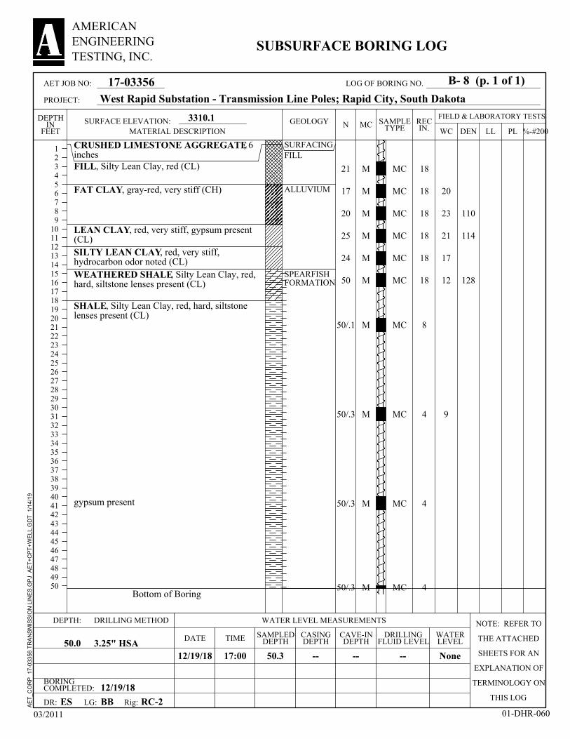
21
17
20
25
24
50
50/.1
50/.3
50/.3
50/.3
CRUSHED LIMESTONE AGGREGATE, 6inchesFILL, Silty Lean Clay, red (CL)
FAT CLAY, gray-red, very stiff (CH)
LEAN CLAY, red, very stiff, gypsum present(CL)SILTY LEAN CLAY, red, very stiff,hydrocarbon odor noted (CL)WEATHERED SHALE, Silty Lean Clay, red,hard, siltstone lenses present (CL)
SHALE, Silty Lean Clay, red, hard, siltstonelenses present (CL)
gypsum present
Bottom of Boring
110
114
128
SURFACINGFILL
ALLUVIUM
SPEARFISHFORMATION
18
18
18
18
18
18
8
4
4
4
M
M
M
M
M
M
M
M
M
M
MC
MC
MC
MC
MC
MC
MC
MC
MC
MC
20
23
21
17
12
9
BORINGCOMPLETED: 12/19/18
CAVE-INDEPTH
12/19/18 None
CASINGDEPTH
LG:
50.3
DEPTH:
DRILLINGFLUID LEVELDATE
--3.25" HSA
SURFACE ELEVATION:
RC-2
DRILLING METHOD NOTE: REFER TO
THE ATTACHED
SHEETS FOR AN
EXPLANATION OF
TERMINOLOGY ON
THIS LOGES
--
SAMPLEDDEPTH50.0
WATER LEVEL MEASUREMENTS
TIME
DR:
--
3310.1
BB
WATERLEVEL
17:00
Rig:
FIELD & LABORATORY TESTSMC
DEN
123456789
1011121314151617181920212223242526272829303132333435363738394041424344454647484950
DEPTHIN
FEET WC PLLL %-#200N REC
IN.
03/2011 01-DHR-060
17-03356
AMERICANENGINEERINGTESTING, INC.
SUBSURFACE BORING LOG
SAMPLETYPE
GEOLOGY
West Rapid Substation - Transmission Line Poles; Rapid City, South Dakota
MATERIAL DESCRIPTION
AET JOB NO:
PROJECT:
B- 8 (p. 1 of 1)LOG OF BORING NO.
AE
T_C
OR
P
17-0
3356
TR
AN
SM
ISS
ION
LIN
ES
.GP
J A
ET
+C
PT
+W
ELL
.GD
T
1/1
4/1
9

5
Boring Sample Depth Dry Density % Moisture2 3 7.5-9' 110.7 pcf 16.1%
Project: Job Number: 17-03356Location: Date: 1/2/2019
UNCONFINED COMPRESSION TEST RESULTS
Test ResultsStress at Failure Strain at Failure
2165 psf 9.5%
West Rapid Substation - Transmission Line PolesRapid City, South Dakota
Project Information
0
500
1,000
1,500
2,000
2,500
0.0% 2.0% 4.0% 6.0% 8.0% 10.0% 12.0% 14.0% 16.0%
Stre
ss (p
sf)
Strain (%)
Stress vs. Strain

5
Boring Sample Depth Dry Density % Moisture5 9 35-36.5 127.7 pcf 12.1%
Project: Job Number: 17-03356Location: Date: 1/2/2018
UNCONFINED COMPRESSION TEST RESULTS
Test ResultsStress at Failure Strain at Failure
2118 pcf 5.3%
West Rapid Substation - Transmission Line PolesRapid City, South Dakota
Project Information
0
500
1,000
1,500
2,000
2,500
0.0% 1.0% 2.0% 3.0% 4.0% 5.0% 6.0% 7.0% 8.0% 9.0%
Stre
ss (p
sf)
Strain (%)
Stress vs. Strain

5
Boring Sample Depth Dry Density % Moisture8 6 15-16.5' 128.4 pcf 12.2%
Project: Job Number: 17-03356Location: Date: 1/2/2018
UNCONFINED COMPRESSION TEST RESULTS
Test ResultsStress at Failure Strain at Failure
2,112 psf 5.6%
West Rapid Substation - Transmission Line PolesRapid City, South Dakota
Project Information
0
500
1,000
1,500
2,000
2,500
0.0% 1.0% 2.0% 3.0% 4.0% 5.0% 6.0% 7.0% 8.0% 9.0% 10.0%
Stre
ss (p
sf)
Strain (%)
Stress vs. Strain
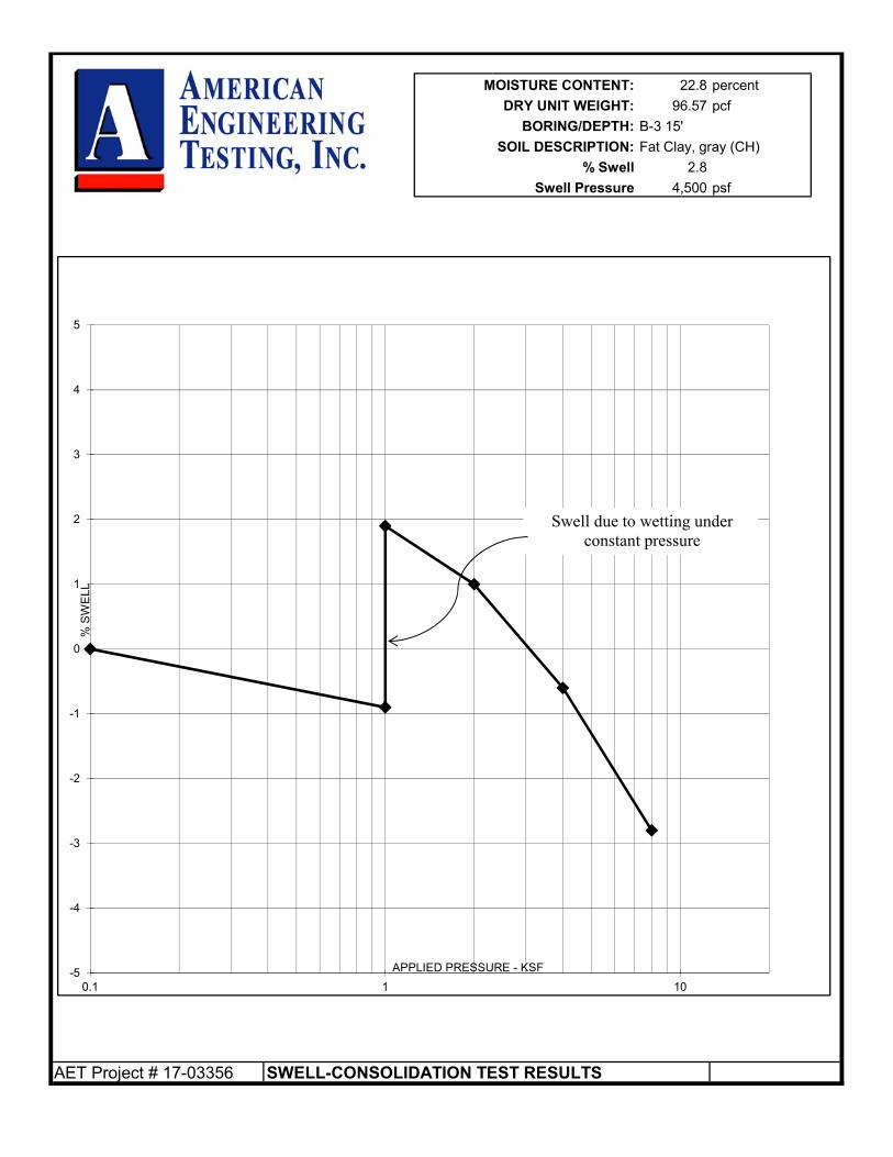
MOISTURE CONTENT: 22.8 percent
DRY UNIT WEIGHT: 96.57 pcf
BORING/DEPTH: B-3 15'
SOIL DESCRIPTION: Fat Clay, gray (CH)
% Swell 2.8
Swell Pressure 4,500 psf
AET Project # 17-03356 SWELL-CONSOLIDATION TEST RESULTS
-5
-4
-3
-2
-1
0
1
2
3
4
5
0.1 1 10
% S
WE
LL
APPLIED PRESSURE - KSF
Swell due to wetting under constant pressure

Report of Geotechnical Exploration and Review West Rapid Substation Transmission Line Poles – Rapid City, South Dakota AMERICAN January 16, 2019 ENGINEERING Report No. 17-03356 TESTING, INC.
Appendix B
Geotechnical Report Limitations and Guidelines for Use
Geotechnical Report Limitations and Guidelines for Use AET Project No. 17-03356
Appendix - Page 1 of 2 AMERICAN ENGINEERING TESTING, INC.
REFERENCE This appendix provides information to help you manage your risks relating to subsurface problems which are caused by construction delays, cost overruns, claims, and disputes. This information was developed and provided by ASFE1, of which, we are a member firm. RISK MANAGEMENT INFORMATION Geotechnical Services are Performed for Specific Purposes, Persons, and Projects Geotechnical engineers structure their services to meet the specific needs of their clients. A geotechnical engineering study conducted for a civil engineer may not fulfill the needs of a construction contractor or even another civil engineer. Because each geotechnical engineering study is unique, each geotechnical engineering report is unique, prepared solely for the client. No one except you should rely on your geotechnical engineering report without first conferring with the geotechnical engineer who prepared it. No one, not even you, should apply the report for any purpose or project except the one originally contemplated. Read the Full Report Serious problems have occurred because those relying on a geotechnical engineering report did not read it all. Do not rely on an executive summary. Do not read selected elements only. A Geotechnical Engineering Report is Based on A Unique Set of Project-Specific Factors Geotechnical engineers consider a number of unique, project-specific factors when establishing the scope of a study. Typically factors include: the client’s goals, objectives, and risk management preferences; the general nature of the structure involved, its size, and configuration; the location of the structure on the site; and other planned or existing site improvements, such as access roads, parking lots, and underground utilities. Unless the geotechnical engineer who conducted the study specifically indicates otherwise, do not rely on a geotechnical engineering report that was:
• not prepared for you, • not prepared for your project, • not prepared for the specific site explored, or • completed before important project changes were made.
Typical changes that can erode the reliability of an existing geotechnical engineering report include those that affect:
• the function of the proposed structure, as when it’s changed from a parking garage to an office building, or from a light industrial plant to a refrigerated warehouse,
• elevation, configuration, location, orientation, or weight of the proposed structure, • composition of the design team, or • project ownership.
As a general rule, always inform your geotechnical engineer of project changes, even minor ones, and request an assessment of their impact. Geotechnical engineers cannot accept responsibility or liability for problems that occur because their reports do not consider developments of which they were not informed. Subsurface Conditions Can Change A geotechnical engineering report is based on conditions that existed at the time the study was performed. Do not rely on a geotechnical engineering report whose adequacy may have been affected by: the passage of time; by man-made events, such as construction on or adjacent to the site; or by natural events, such as floods, earthquakes, or groundwater fluctuations. Always contact the geotechnical engineer before applying the report to determine if it is still reliable. A minor amount of additional testing or analysis could prevent major problems. 1 ASFE, 8811 Colesville Road/Suite G106, Silver Spring, MD 20910 Telephone: 301/565-2733 : www.asfe.org
Geotechnical Report Limitations and Guidelines for Use AET Project No. 17-03356
Appendix - Page 2 of 2 AMERICAN ENGINEERING TESTING, INC.
Most Geotechnical Findings Are Professional Opinions Site exploration identified subsurface conditions only at those points where subsurface tests are conducted or samples are taken. Geotechnical engineers review field and laboratory data and then apply their professional judgment to render an opinion about subsurface conditions throughout the site. Actual subsurface conditions may differ, sometimes significantly, from those indicated in your report. Retaining the geotechnical engineer who developed your report to provide construction observation is the most effective method of managing the risks associated with unanticipated conditions. A Report’s Recommendations Are Not Final Do not over rely on the construction recommendations included in your report. Those recommendations are not final, because geotechnical engineers develop them principally from judgment and opinion. Geotechnical engineers can finalize their recommendations only by observing actual subsurface conditions revealed during construction. The geotechnical engineer who developed your report cannot assume responsibility or liability for the report’s recommendations if that engineer does not perform construction observation. A Geotechnical Engineering Report Is Subject to Misinterpretation Other design team members’ misinterpretation of geotechnical engineering reports has resulted in costly problems. Lower that risk by having your geotechnical engineer confer with appropriate members of the design team after submitting the report. Also retain your geotechnical engineer to review pertinent elements of the design team’s plans and specifications. Contractors can also misinterpret a geotechnical engineering report. Reduce that risk by having your geotechnical engineer participate in prebid and preconstruction conferences, and by providing construction observation. Do Not Redraw the Engineer’s Logs Geotechnical engineers prepare final boring and testing logs based upon their interpretation of field logs and laboratory data. To prevent errors or omissions, the logs included in a geotechnical engineering report should never be redrawn for inclusion in architectural or other design drawings. Only photographic or electronic reproduction is acceptable, but recognize that separating logs from the report can elevate risk. Give Contractors a Complete Report and Guidance Some owners and design professionals mistakenly believe they can make contractors liable for unanticipated subsurface conditions by limiting what they provide for bid preparation. To help prevent costly problems, give contractors the complete geotechnical engineering report, but preface it with a clearly written letter of transmittal. In the letter, advise contractors that the report was not prepared for purposes of bid development and that the report’s accuracy is limited; encourage them to confer with the geotechnical engineer who prepared the report (a modest fee may be required) and/or to conduct additional study to obtain the specific types of information they need to prefer. A prebid conference can also be valuable. Be sure contractors have sufficient time to perform additional study. Only then might you be in a position to give contractors the best information available to you, while requiring them to at least share some of the financial responsibilities stemming from unanticipated conditions. Read Responsibility Provisions Closely Some clients, design professionals, and contractors do not recognize that geotechnical engineering is far less exact than other engineering disciplines. This lack of understanding has created unrealistic expectations that have led to disappointments, claims, and disputes. To help reduce the risk of such outcomes, geotechnical engineers commonly include a variety of explanatory provisions in their report. Sometimes labeled “limitations” many of these provisions indicate where geotechnical engineers’ responsibilities begin and end, to help others recognize their own responsibilities and risks. Read these provisions closely. Ask questions. Your geotechnical engineer should respond fully and frankly. Geoenvironmental Concerns Are Not Covered The equipment, techniques, and personnel used to perform a geoenvironmental study differ significantly from those used to perform a geotechnical study. For that reason, a geotechnical engineering report does not usually relate any geoenvironmental findings, conclusions, or recommendations; e.g., about the likelihood of encountering underground storage tanks or regulated contaminants. Unanticipated environmental problems have led to numerous project failures. If you have not yet obtained your own geoenvironmental information, ask your geotechnical consultant for risk management guidance. Do not rely on an environmental report prepared for someone else.