Embed Size (px)
Citation preview
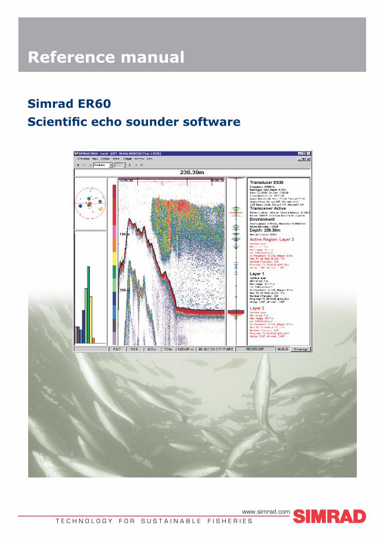
Reference manual
Simrad ER60
Scientific echo sounder software
T E C H N O L O G Y F O R S U S T A I N A B L E F I S H E R I E Swww.simrad.com

Simrad ER60Scientific echo sounder
Reference ManualRelease 2.2.0.
This reference manual describes how to use the SimradER60 scientific echo sounder application. This is thesoftware application used to operate and control the SimradEK60 scientific echo sounder system.
164692/C11 January 2008
Document history
Simrad document number: 164692 / ISBN-13: 978-8066-011-4
Rev.A July 2003 First version.
Rev.B September 2004 Revised for software version 2.1.0.
Rev.C January 2008 Revised for software version 2.2.0. Document transferred toXML format.
Copyright©2008 Kongsberg Maritime ASThe information contained in this document remains the sole property of Kongsberg Maritime AS. No partof this document may be copied or reproduced in any form or by any means, and the information containedwithin it is not to be communicated to a third party, without the prior written consent of KongsbergMaritime AS. The document, or any part of it, may not be translated to any other language without thewritten approval from Kongsberg Maritime AS.
DisclaimerKongsberg Maritime AS endeavours to ensure that all information in this document is correct and fairlystated, but does not accept liability for any errors or omissions.
WarningThe equipment to which this manual applies must only be used for the purpose for which it wasdesigned. Improper use or maintenance may cause damage to the equipment and/or injury to personnel.The user must be familiar with the contents of the appropriate manuals before attempting to install,operate or work on the equipment.Kongsberg Maritime AS disclaims any responsibility for damage or injury caused by improperinstallation, use or maintenance of the equipment.
SupportIf you require maintenance on your Simrad equipment, contact your local dealer. You can also contactSimrad using the following address:[email protected]. If you need other information aboutthis product, or any other Simrad products, visit www.simrad.com. On our web site you will also finda list of our dealers and distributors.
Kongsberg Maritime AS
Strandpromenaden 50
P.O.Box 111
N-3191 Horten, Norway
Simrad
Telephone: +47 33 03 40 00
Telefax: +47 33 04 29 87
www.simrad.com
Reference Manual
Table of contents
INTRODUCTION ................................................................ 9
OPERATIONAL PROCEDURES .......................................... 10Power on/off ........................................................................................................... 11
How to switch power on.............................................................................. 11How to set up transceiver channels............................................................... 11How to switch power off ............................................................................. 12
Basic operation .......................................................................................................13How to change the echogram settings........................................................... 13How to change the range ............................................................................. 13How to change the vertical resolution........................................................... 13How to define minimum and maximum depth............................................... 14
Transceiver installation ..........................................................................................15Background................................................................................................ 15How to install a channel .............................................................................. 15How to disconnect a channel ....................................................................... 15
Data recording and playback..................................................................................16Background................................................................................................ 16How to record raw data ............................................................................... 16How to play back raw data .......................................................................... 17
Calibration ..............................................................................................................19Introduction................................................................................................ 19Preparations and transducer maintenance...................................................... 19Calibration procedures ................................................................................ 20
Noise measurements at sea.....................................................................................32Basic guidelines.......................................................................................... 32Noise measurement procedure ..................................................................... 33Test results ................................................................................................. 35Evaluation .................................................................................................. 35
Multiplexer set-up ..................................................................................................37How to connect the multiplexer ................................................................... 37How to set up the transceiver ....................................................................... 37Technical information ................................................................................. 38
DISPLAY VIEWS.............................................................. 39Display organisation...............................................................................................40Main menu..............................................................................................................41Toolbar....................................................................................................................42Status bar ................................................................................................................43Channel windows ...................................................................................................44
Depth view................................................................................................. 45
164692/C 3
Simrad ER60
Single target position view .......................................................................... 46Single target histogram view........................................................................ 47Echogram view........................................................................................... 48Scope view................................................................................................. 49Colour scale view ....................................................................................... 50Numerical view .......................................................................................... 51
MENU SYSTEM ................................................................ 52Main menu..............................................................................................................53
Operation menu .......................................................................................... 53View menu ................................................................................................. 53Options menu ............................................................................................. 54Install menu................................................................................................ 54Output menu............................................................................................... 55Window menu ............................................................................................ 55Help menu.................................................................................................. 56
Short-cut menus......................................................................................................57Depth short-cut menu.................................................................................. 57Single Target Position short-cut menu .......................................................... 57Single Target Histogram short-cut menu....................................................... 57Echogram short-cut menu............................................................................ 58Scope short-cut menu.................................................................................. 59Colour Scale short-cut menu........................................................................ 59Numerical short-cut menu ........................................................................... 60
REFERENCES ................................................................... 61Alphabetical list of dialogue boxes and functions..................................................61Dialogue box and functions descriptions ...............................................................63
About......................................................................................................... 63Add User Account ...................................................................................... 64Annotation ................................................................................................. 65Bottom Detection........................................................................................ 67Bottom Range............................................................................................. 69Calculation Interval..................................................................................... 70Cascade...................................................................................................... 72Close All .................................................................................................... 73Colour Scale............................................................................................... 74Colours ...................................................................................................... 76Configure Statusbar..................................................................................... 77Configure Window...................................................................................... 78Contents..................................................................................................... 79Data Source................................................................................................ 80Delete Layer............................................................................................... 82Depth Output.............................................................................................. 83
4 164692/C

Reference Manual
Echogram................................................................................................... 84EK500 Datagram ........................................................................................ 90Environment............................................................................................... 94Errors......................................................................................................... 96Ethernet Output .......................................................................................... 97Exit............................................................................................................ 99File Output ............................................................................................... 100HAC Datagram......................................................................................... 106Hide View ................................................................................................ 108Histogram ................................................................................................ 109Horizontal Axis .........................................................................................110LAN Port Setup .........................................................................................111Layer Properties ........................................................................................112Load Settings.............................................................................................114Log In .......................................................................................................115Log Out ....................................................................................................116Motion ......................................................................................................117Navigation ................................................................................................118New Channel............................................................................................ 122New Layer ............................................................................................... 123Normal Operation ..................................................................................... 124Numerical View........................................................................................ 126Open All .................................................................................................. 127Ping Control ............................................................................................. 128Port Management...................................................................................... 130Port Monitor............................................................................................. 133Print......................................................................................................... 135Print Preview............................................................................................ 136Range ...................................................................................................... 138Remoting ................................................................................................. 139Replay ..................................................................................................... 144Save Settings ............................................................................................ 146Serial Port Setup ....................................................................................... 147Single Target Detection ............................................................................. 148Status bar ................................................................................................. 150Surface Range .......................................................................................... 151Tile .......................................................................................................... 153Toolbars ................................................................................................... 154Tooltip ..................................................................................................... 155Transceiver Installation ............................................................................. 156Transducer Parameters .............................................................................. 159Trawl ....................................................................................................... 160User Properties ......................................................................................... 162
164692/C 5
Simrad ER60
Users and Passwords................................................................................. 163Warnings.................................................................................................. 165
DATA FORMATS............................................................. 166Numeric type definition........................................................................................167Raw data ...............................................................................................................168
Data encapsulation.................................................................................... 169Configuration datagram............................................................................. 170NMEA datagrams ..................................................................................... 171Annotation datagrams ............................................................................... 172Sample datagram ...................................................................................... 173
Data subscriptions and remote control .................................................................174Data subscriptions overview ...................................................................... 175Request server information........................................................................ 176Connecting to server ................................................................................. 177Keep connection alive ............................................................................... 179Issue commands on the server.................................................................... 180Collecting data ......................................................................................... 183Parameter management ............................................................................. 187Disconnecting from server......................................................................... 190
Data subscription types ........................................................................................191Bottom detection ...................................................................................... 192Target strength (TS) detection.................................................................... 193Sample data.............................................................................................. 195Echogram................................................................................................. 197Targets echogram...................................................................................... 198Integration................................................................................................ 199Targets integration .................................................................................... 200
Parameter descriptions .........................................................................................202NMEA telegram specifications ............................................................................205
GGA Global positioning system fix data..................................................... 205GLL Geographical position latitude/longitude ............................................ 206HDG Heading, deviation and variation....................................................... 206HDM Heading, magnetic........................................................................... 206HDT Heading, true ................................................................................... 207RMC Recommended minimum specific GNSS data .................................... 207VHWWater speed and heading ................................................................. 207VLW Dual ground/water distance .............................................................. 208VTG Course over ground and Ground speed............................................... 208
Proprietary telegram specifications ......................................................................209ATS Annotation........................................................................................ 209DBS Depth of trawl below surface ............................................................. 209HFB Trawl headrope to footrope and bottom .............................................. 209
6 164692/C

Reference Manual
TPT Trawl position true vessel .................................................................. 210Ifremer trawl datagram.............................................................................. 210Kongsberg EM Attitude 1000 .................................................................... 212Kongsberg EM Attitude 3000 .................................................................... 213Sounder attitude........................................................................................ 214
164692/C 7

Simrad ER60
8 164692/C
Introduction
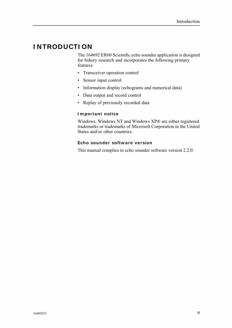
INTRODUCTIONThe 164692 ER60 Scientific echo sounder application is designedfor fishery research and incorporates the following primaryfeatures:• Transceiver operation control• Sensor input control• Information display (echograms and numerical data)• Data output and record control• Replay of previously recorded data
Important notice
Windows, Windows NT and Windows XP® are either registeredtrademarks or trademarks of Microsoft Corporation in the UnitedStates and/or other countries.
Echo sounder software version
This manual complies to echo sounder software version 2.2.0.
164692/C 9
Simrad ER60
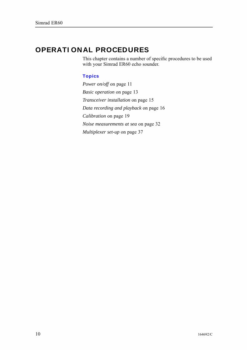
OPERATIONAL PROCEDURESThis chapter contains a number of specific procedures to be usedwith your Simrad ER60 echo sounder.
Topics
Power on/off on page 11Basic operation on page 13Transceiver installation on page 15Data recording and playback on page 16Calibration on page 19Noise measurements at sea on page 32Multiplexer set-up on page 37
10 164692/C

Operational procedures
Power on/offUse the following procedures to switch the ER60 echo sounderon and off.
Related topics
Log In on page 115Exit on page 99Transceiver Installation on page 156Normal Operation on page 124New Channel on page 122
How to switch power onIt is assumed that the echo sounder’s hardware and software areproperly installed and set up.1 Switch power on.
• The location of the power switches are individuallyassigned. The computer has its own power switch. Thetransceiver(s) must be connected to separate powersupplies, and should have a remote power switch.
2 Observe the hardware test messages and operating systemstart-up messages.
3 Start the ER60 program.4 If the Login dialogue box appears, enter user name and
password.5 Select Operation →Normal.6 Once the echo sounder is running, start pinging by pressing
the “Start” button on the toolbar.
Figure 1 The “Start” button on the toolbar
How to set up transceiver channelsIf no channels appear in the Normal Operation dialogue, observethe following procedure.1 Click Install →Transceiver to open the Transceiver
Installation dialogue.2 Check that all frequency channels are properly installed.3 Click Operation →Normal to open the Normal Operation
dialogue.4 Check the operational mode for each of the installed
channels. Adjust as required.
164692/C 11

Simrad ER60
5 ClickWindow→New channel to open a new channel window.
How to switch power offTo switch off the ER60 echo sounder, observe the followingprocedure.1 Click File →Exit.2 Allow the computer to close all the ER60 software
applications.• If desired, ER60 can be restarted using the desktop icon.
3 Switch off the power on the General Purpose Transceiver(GPT) and other peripherals (if any).
When the ER60 software has closed down, you need to closedown the computer as well.
12 164692/C
Operational procedures
Basic operationThis chapter presents a number of common procedures frequentlycarried out on the ER60 echo sounder.
Related topics
Echogram view on page 48Depth view on page 45Echogram on page 84Bottom Range on page 69Surface Range on page 151Normal Operation on page 124Bottom Detection on page 67
How to change the echogram settingsTo change the echogram settings:1 Position the cursor in the Echogram view.2 Click the right mouse button.3 Click Echogram on the short-cut menu, and observe that
the Echogram dialogue opens.4 Make the desired changes.5 Click Ok.
How to change the rangeTo change the range:1 Position the cursor in the Echogram view.2 Click the right mouse button.3 Click Range on the short-cut menu, and observe that either
the Bottom Range or the Surface Range dialogue opens(depending on the current setting).
4 Make the desired changes.5 Click Ok.
How to change the vertical resolutionThe vertical resolution of the echogram increases with a shorterpulse duration.Example: A pulse duration of 1.024 millisecond gives a verticalresolution of 19.2 cm, whereas a pulse duration of 0.256millisecond gives a vertical resolution of 4.8 cm. If the verticaldistance between two echoes is less than this, the two echoes willbe shown as one.Observe the following procedure to change the pulse duration:
164692/C 13
Simrad ER60
1 Click Operation →Normal, and observe that the NormalOperation dialogue opens.
2 Set the desired pulse duration for each of the frequencychannels.
3 Click Ok.A small value gives the best resolution, while larger valuesprovides you with a longer detection range.
How to define minimum and maximumdepthSetting the minimum and maximum depth enables the echosounder to search for bottom lock.
Note
Setting both Minimum Depth and Maximum Depth to 0 m willturn off bottom detection.
1 Position the cursor over the depth information in the Depthview.
2 Click the right mouse button.3 Click Bottom Detector on the short-cut menu, and observe
that the Bottom Detection dialogue opens.4 Set minimum and maximum depth to the desired values.5 Click Ok.
14 164692/C
Operational procedures
Transceiver installationUse the following procedures to install, modify or deletefrequency channels from the echo sounder setup.
Related topics
Transceiver Installation on page 156
BackgroundGeneral Purpose Transceivers (GPT) physically connected to theecho sounder’s ethernet interface are identified automatically bythe system. When you open the Transceiver Installation dialoguebox from the Install menu, a list will be provided. A singlefrequency transceiver occupies one entry in the list. This entryis identified as a Frequency Channel, and the line displays theparameters for the channel. Entries in the frequency channellist are shown in black, green, blue or red colour identifying itscurrent status.
How to install a channelTo install a channel:1 Click Install→Transceiver, and observe that the Transceiver
Installation dialogue opens.2 Click the desired entry (one of the black colour line
alternatives) in the Frequency Channel Selection list.3 Assign a transducer by clicking a transducer name in the
Transducer Selection list.4 Click Ok.
How to disconnect a channelTo disconnect a channel:1 Click Install→Transceiver, and observe that the Transceiver
Installation dialogue opens.2 Click the desired entry in the Frequency Channel Selection
list.3 Select the alternative None in the Transducer Selection list.4 Click Ok.
164692/C 15
Simrad ER60
Data recording and playbackUse the following procedures to install, modify or deletefrequency channels from the echo sounder setup.
Related topics
File Output on page 100Replay on page 144
BackgroundYou can set up the echo sounder to record unprocessed transducersignals (sample data) and external sensor information onto files.These files contain the necessary information to reconstruct thesituation during the real survey. The echo sounder program readsthese files during replay.
How to record raw dataObserve these procedures to record data.
Preparations
1 Click File →Output, and observe that the File Outputdialogue opens.
2 Click the Directory tab, and click the Browse button if youwish to change the directory to which the files are stored.
3 Click the Raw Data tab to define how the raw data is to berecorded.• Save raw data: Start/stop recording of raw data.• Range: Select the depth range to be recorded. This range,referring to the transducer face, is independent of anyother range settings in the echo sounder.
• Echogram data: This is user defined excerpts of theprocessed sample data (pixel data), ie the backscattervalue of the targets. The echograms are stored as timetagged datagrams in separate files.
4 Click Ok to exit the dialogue.
Start and stop recording
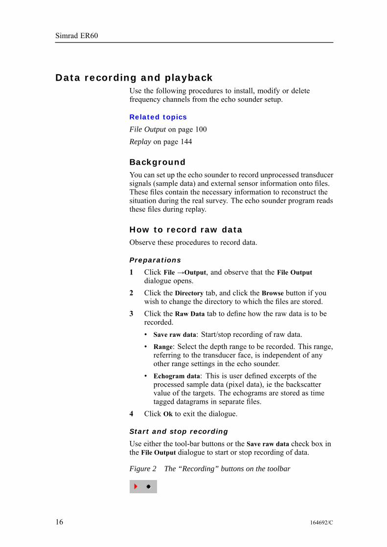
Use either the tool-bar buttons or the Save raw data check box inthe File Output dialogue to start or stop recording of data.
Figure 2 The “Recording” buttons on the toolbar
16 164692/C
Operational procedures
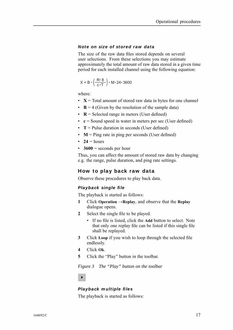
Note on size of stored raw data
The size of the raw data files stored depends on severaluser selections. From these selections you may estimateapproximately the total amount of raw data stored in a given timeperiod for each installed channel using the following equation:
X = B M 24 3600R 8
c T
where:• X = Total amount of stored raw data in bytes for one channel• B = 4 (Given by the resolution of the sample data)• R = Selected range in meters (User defined)• c = Sound speed in water in meters per sec (User defined)• T = Pulse duration in seconds (User defined)• M = Ping rate in ping per seconds (User defined)• 24 = hours• 3600 = seconds per hourThus, you can affect the amount of stored raw data by changinge.g. the range, pulse duration, and ping rate settings.
How to play back raw dataObserve these procedures to play back data.
Playback single file
The playback is started as follows:1 Click Operation →Replay, and observe that the Replay
dialogue opens.2 Select the single file to be played.
• If no file is listed, click the Add button to select. Notethat only one replay file can be listed if this single fileshall be replayed.
3 Click Loop if you wish to loop through the selected fileendlessly.
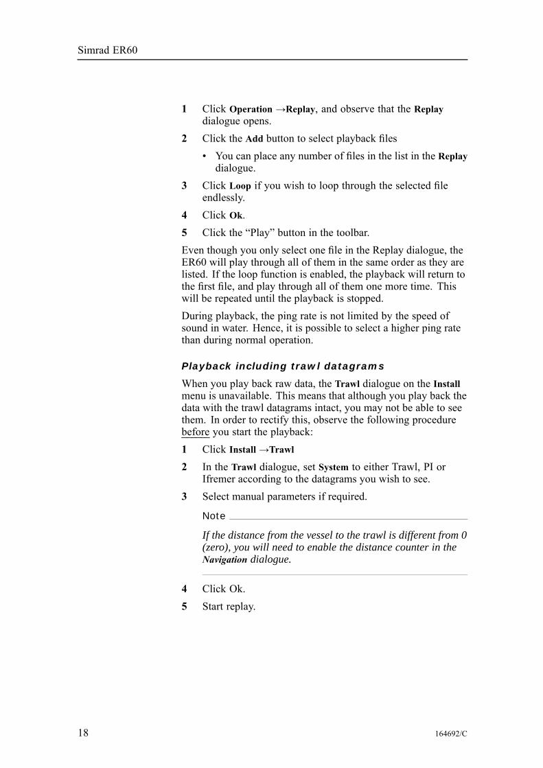
4 Click Ok.5 Click the “Play” button in the toolbar.
Figure 3 The “Play” button on the toolbar
Playback multiple files
The playback is started as follows:
164692/C 17
Simrad ER60
1 Click Operation →Replay, and observe that the Replaydialogue opens.
2 Click the Add button to select playback files• You can place any number of files in the list in the Replaydialogue.
3 Click Loop if you wish to loop through the selected fileendlessly.
4 Click Ok.5 Click the “Play” button in the toolbar.Even though you only select one file in the Replay dialogue, theER60 will play through all of them in the same order as they arelisted. If the loop function is enabled, the playback will return tothe first file, and play through all of them one more time. Thiswill be repeated until the playback is stopped.During playback, the ping rate is not limited by the speed ofsound in water. Hence, it is possible to select a higher ping ratethan during normal operation.
Playback including trawl datagrams
When you play back raw data, the Trawl dialogue on the Installmenu is unavailable. This means that although you play back thedata with the trawl datagrams intact, you may not be able to seethem. In order to rectify this, observe the following procedurebefore you start the playback:1 Click Install →Trawl2 In the Trawl dialogue, set System to either Trawl, PI or
Ifremer according to the datagrams you wish to see.3 Select manual parameters if required.
Note
If the distance from the vessel to the trawl is different from 0(zero), you will need to enable the distance counter in theNavigation dialogue.
4 Click Ok.5 Start replay.
18 164692/C
Operational procedures
CalibrationFor acoustic surveys where accurate quantitative measurementsare required it is essential that the echo sounder is correctlycalibrated. It is a safe practice to perform the calibration beforeand after the survey. If experiences over time show that noadjustments are necessary, it may be appropriate to reconsiderthe need for frequent calibrations. Simrad recommends thatcalibration is performed at least once a year, and in areas withdifferent summer and winter condition at least twice a year.
IntroductionDuring calibration a reference target with known target strengthis lowered into the sound beam, and the measured target strengthis compared with the known target strength. If it is necessaryto adjust the echo sounder, this is performed automatically bythe ER60 calibration software. Since the echo sounder is digitalright from the receiver front end, no analogue gain adjustmentis required.The reference target is normally a metal sphere. Simrad suppliesa variety of copper spheres, one for each frequency. The spherediameter is selected for minimum temperature dependence.
Preparations and transducer maintenanceThe transducer is heavily exposed to fouling. Make sure that thetransducer face is painted after installation, and that the paint ismaintained whenever the vessel is in dry dock. Always use anapproved anti-fouling paint.Depending on the environmental conditions where the vesseloperates, fouling must be removed from time to time. Failing todo so will degrade the echo sounder performance. Use a softpiece of wood and remove the fouling carefully. Afterwards, usea very fine grade emery paper.
Note
Do not remove fouling with a metal tool or wire brush.
164692/C 19
Simrad ER60
Calibration proceduresThis section holds the calibration procedures.
Topics
Check installation on page 20Anchoring on page 21Winches on page 22Attaching the sphere on page 23Lowering the sphere on page 24Reference target on page 24Calibration on page 25Views on page 27Data editing on page 29Updating transducer parameters on page 30Previously recorded data on page 30Offline calibration on page 30
Check installation
1 Check that the ER60 and all the transceivers and transducersare installed correctly, and that they are all fully functional.
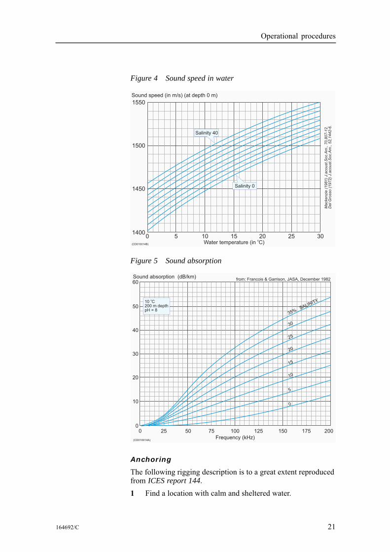
2 Measure the water salinity and temperature between thetransducer and the sphere depth.
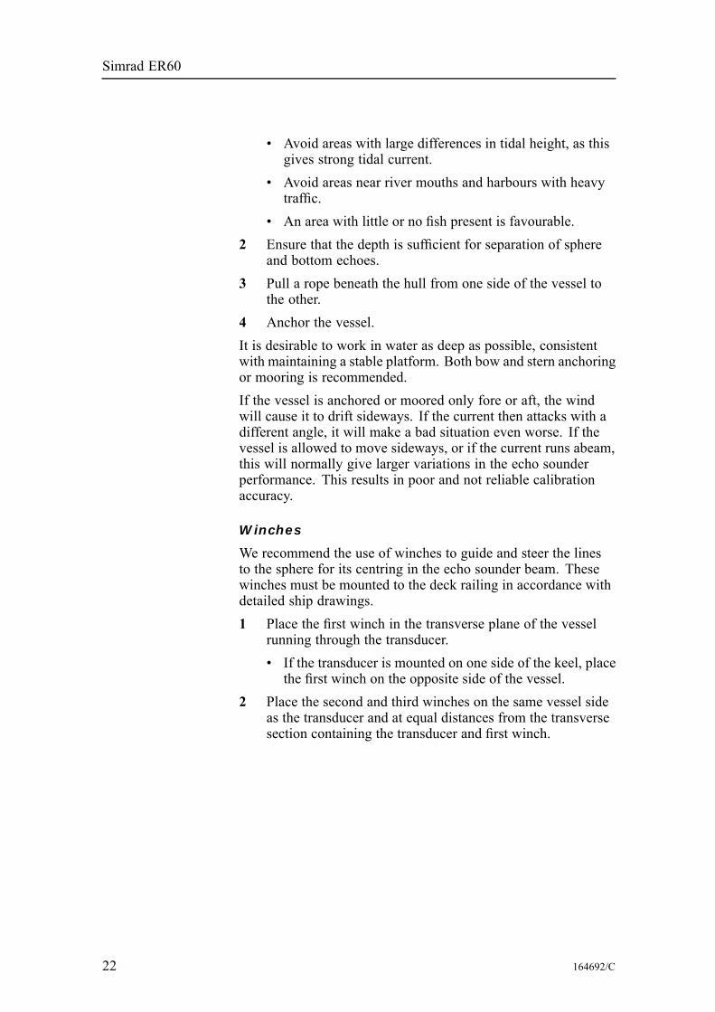
3 Calculate the average salinity and temperature values, andenter these data in the Environment dialogue box.• The sound velocity is automatically calculated by theecho sounder.
• The corresponding absorption coefficient is calculatedby the echo sounder according to Francois & Garrison,JASA December 1982.
• For additional information about the dialogue box, seeEnvironment on page 94.
Note
When you calculate the target strength (TS), you must usethe sound velocity at the sphere’s depth.
4 Use the ER60 to check that operation in Normal modefunctions properly for all transducers.
20 164692/C
Operational procedures
Figure 4 Sound speed in water
1550
Sound speed (in m/s) (at depth 0 m)
Mackenzie
(1981)
J.a
coust.S
oc.A
m.,
70,8
07-1
2.
DelG
rosso
(1972)
J.a
coust.S
oc.A
m.,
52,1
442-6
.
1500
1450
14000 5 10
Water temperature (in C)o
15 20 25 30(CD010014B)
Salinity 0
Salinity 40
Figure 5 Sound absorption
Frequency (kHz)
Sound absorption (dB/km)
0
(CD010014A)
0
10
20
30
40
50
60
25 50 75 100 125 150 175 200
35%SALINITY
30
25
20
15
10
5
0
from: Francois & Garrison, JASA, December 1982
10 C200 m depthpH = 8
o
Anchoring
The following rigging description is to a great extent reproducedfrom ICES report 144.1 Find a location with calm and sheltered water.
164692/C 21
Simrad ER60
• Avoid areas with large differences in tidal height, as thisgives strong tidal current.
• Avoid areas near river mouths and harbours with heavytraffic.
• An area with little or no fish present is favourable.2 Ensure that the depth is sufficient for separation of sphere
and bottom echoes.3 Pull a rope beneath the hull from one side of the vessel to
the other.4 Anchor the vessel.It is desirable to work in water as deep as possible, consistentwith maintaining a stable platform. Both bow and stern anchoringor mooring is recommended.If the vessel is anchored or moored only fore or aft, the windwill cause it to drift sideways. If the current then attacks with adifferent angle, it will make a bad situation even worse. If thevessel is allowed to move sideways, or if the current runs abeam,this will normally give larger variations in the echo sounderperformance. This results in poor and not reliable calibrationaccuracy.
Winches
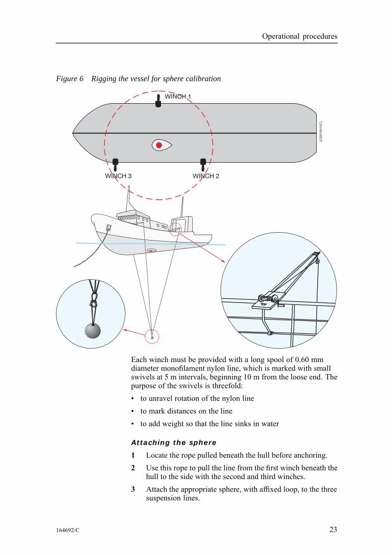
We recommend the use of winches to guide and steer the linesto the sphere for its centring in the echo sounder beam. Thesewinches must be mounted to the deck railing in accordance withdetailed ship drawings.1 Place the first winch in the transverse plane of the vessel
running through the transducer.• If the transducer is mounted on one side of the keel, placethe first winch on the opposite side of the vessel.
2 Place the second and third winches on the same vessel sideas the transducer and at equal distances from the transversesection containing the transducer and first winch.
22 164692/C
Operational procedures
Figure 6 Rigging the vessel for sphere calibration
WINCH 2WINCH 3
WINCH 1
(CD
010014C
)
Each winch must be provided with a long spool of 0.60 mmdiameter monofilament nylon line, which is marked with smallswivels at 5 m intervals, beginning 10 m from the loose end. Thepurpose of the swivels is threefold:• to unravel rotation of the nylon line• to mark distances on the line• to add weight so that the line sinks in water
Attaching the sphere
1 Locate the rope pulled beneath the hull before anchoring.2 Use this rope to pull the line from the first winch beneath the
hull to the side with the second and third winches.3 Attach the appropriate sphere, with affixed loop, to the three
suspension lines.
164692/C 23
Simrad ER60
For the smaller spheres it may be necessary to add a weight tokeep the sphere stable. This is done via a second line attached tothe three suspension lines. The length of the line must be at leasttwo pulse lengths, so that the echo from the additional weightdoes not interfere with the sphere echo. Immerse the spherein a solution of dishwasher detergent and freshwater and lift itoverboard by the fastened lines without touching it. The soaphelps to eliminate air bubbles attached to the sphere.
Lowering the sphere
Lower the sphere beneath the vessel to the desired depth, forexample 25 m, which is determined roughly by counting theswivels on each line.The required depth is mainly determined by the transducer beamwidth and the vessel geometry. The physical width of the beam,which increases linearly with range, should be sufficiently greatso that the sphere echo is unaffected by the small movements towhich it is inevitably subjected.In most cases calibration will be performed at depths larger than10 m. However, the chosen depth should be limited to ensurethat it is possible to cover the entire beam. The minimal depthmust also be convenient with respect to the vessel geometry.In particular, if the suspension lines do not hang freely, thencontrol of the sphere may be hindered by friction or possibleobstructions on the hull. Despite the number and variety of theseconsiderations, it is seldom difficult in practice to find a suitabledepth, which satisfies all of the above criteria.
Reference target
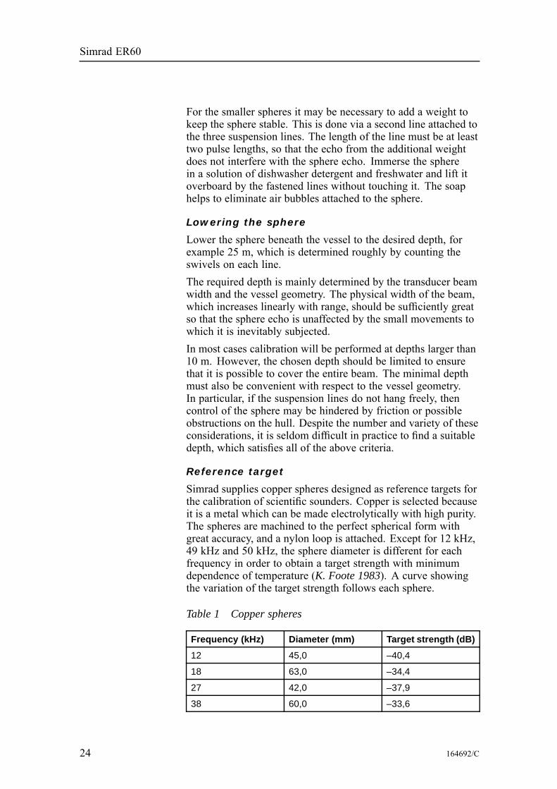
Simrad supplies copper spheres designed as reference targets forthe calibration of scientific sounders. Copper is selected becauseit is a metal which can be made electrolytically with high purity.The spheres are machined to the perfect spherical form withgreat accuracy, and a nylon loop is attached. Except for 12 kHz,49 kHz and 50 kHz, the sphere diameter is different for eachfrequency in order to obtain a target strength with minimumdependence of temperature (K. Foote 1983). A curve showingthe variation of the target strength follows each sphere.
Table 1 Copper spheres
Frequency (kHz) Diameter (mm) Target strength (dB)
12 45,0 –40,4
18 63,0 –34,4
27 42,0 –37,9
38 60,0 –33,6
24 164692/C
Operational procedures
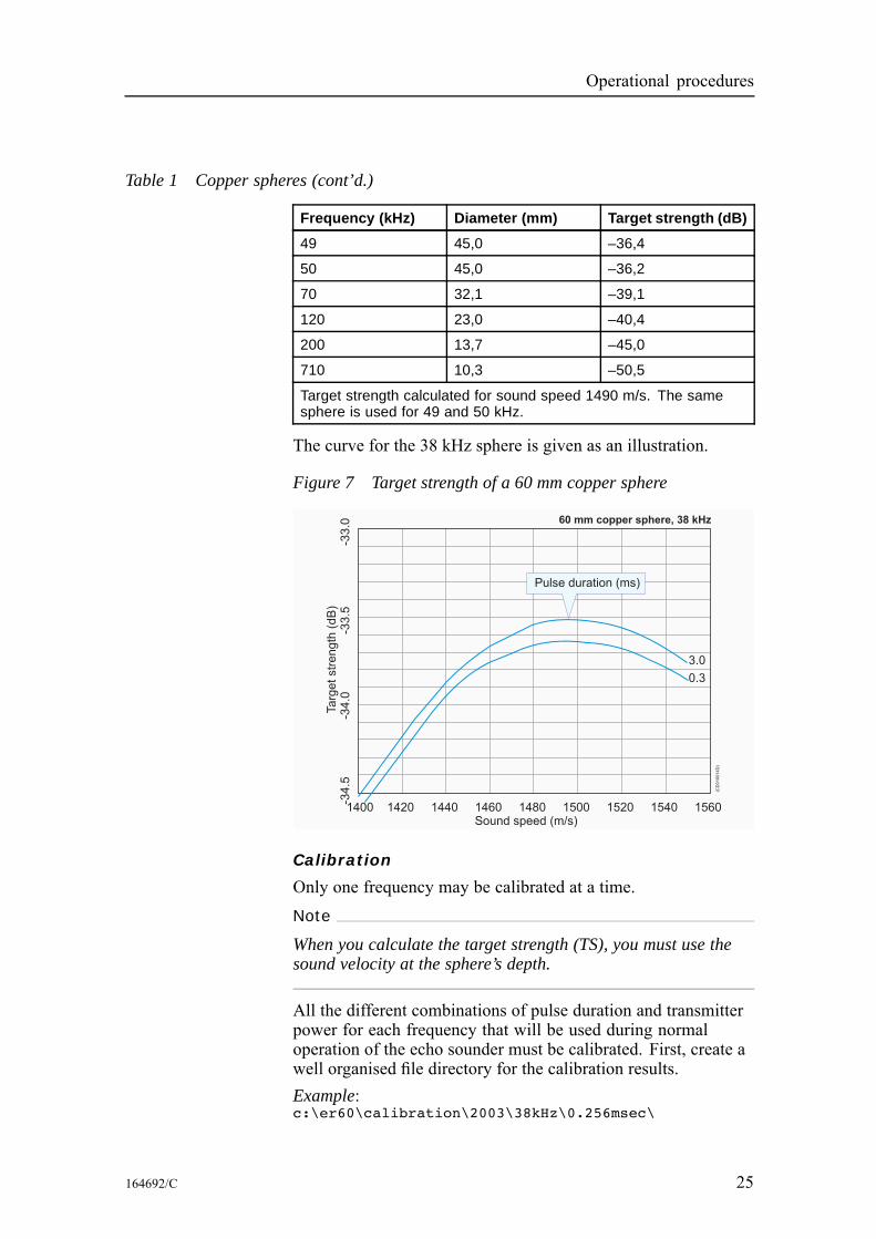
Table 1 Copper spheres (cont’d.)
Frequency (kHz) Diameter (mm) Target strength (dB)
49 45,0 –36,4
50 45,0 –36,2
70 32,1 –39,1
120 23,0 –40,4
200 13,7 –45,0
710 10,3 –50,5
Target strength calculated for sound speed 1490 m/s. The samesphere is used for 49 and 50 kHz.
The curve for the 38 kHz sphere is given as an illustration.
Figure 7 Target strength of a 60 mm copper sphere
60 mm copper sphere, 38 kHz
1400 1420 1440 1460 1480 1500 1520 1540 1560Sound speed (m/s)
Targ
etstr
ength
(dB
)-3
4.5
-34.0
-33.5
-33.0
3.0
0.3
(CD
010014D
)
Pulse duration (ms)
Calibration
Only one frequency may be calibrated at a time.Note
When you calculate the target strength (TS), you must use thesound velocity at the sphere’s depth.
All the different combinations of pulse duration and transmitterpower for each frequency that will be used during normaloperation of the echo sounder must be calibrated. First, create awell organised file directory for the calibration results.Example:c:\er60\calibration\2003\38kHz\0.256msec\
164692/C 25
Simrad ER60
The same structure can be repeated for the different pulseduration for each frequency. When you save the calibration file,create a file name that includes the current date and the currentoutput power. Save the information as a TXT file.Example:....\0.256msec\cal010603-2000w.txt
While the calibration takes place, we recommend that you alsocollect a raw data file. Browse the file directory in the Storedialogue box to locate the correct directory. The raw data filename will be generated automatically, but you may specify aprefix. The raw data file is used for replay.The same procedure can be repeated for each of the installedfrequencies. Observe the following calibration procedure.1 Click Operation →Ping control.2 In the Ping Control dialogue, set Ping rate to Interval and
1 second.• This can also be done from the toolbar.
3 Click Operation →Normal.4 In the Normal Operation dialogue:
1 Select transceiver, and switch to Active mode.2 Set the Transmit Power to the level you wish to
calibrate.3 Choose the Pulse Duration you wish to calibrate.
5 Right-click in an echogram, select Range on the short-cutmenu, and set the range for one of the echogram views tocover the range you wish to see.• This range should include the depth range where youexpect to find the reference target.
6 Check that you see the reference target in the Single Echoview.
7 Right-click in the Single Echo view corresponding to theechogram to open the Single Target Detection dialogue box.
8 In the Single Target Detection dialogue, click the Calibrationbutton to start the calibration program, and to create a newCalibration window.• The calibration program allows you to record newcalibration data, or read previously recorded calibrationdata.
9 In the Calibration window, click File →New to open theRecord dialogue and to start a new calibration.
10 Enter the following data in the Record dialogue box:1 Transducer’s serial number
26 164692/C
Operational procedures
2 Correct theoretical target strength (TS) for the referencetarget
3 Allowed deviation from the TS for the reference target• This is a window giving the limits for the system’sacceptance of single target echoes coming fromfish. The closer to the correct reference target TSthe limits have been set, the more of the unwantedfish echoes will be rejected. On the other hand, ifthe echo from the reference target is too close toone of the limits, the deviation has to be increasedbefore starting collecting data. This is because itwill always be a certain variation in TS values whenthe reference target is being moved to cover thecomplete beam.
4 Upper and lower depth limits for the target window• A narrow window will have same effect as above,reducing the possibility of detecting unwantedechoes from fish.
5 Any comments you may wish to add to the calibrationfile
11 Click OK when you have finished entering data.The calibration program will now begin recording data.
Views
You will see two views in the Calibration window; a Plot viewand an Information view.A vertical bar is shown on the left side of each view. A bluecolour indicates that the view is active, while gray colourindicates a passive view. If you wish to print a view, or performother operations connected to it, you must make sure that thedesired view is active.In the Plot view you will see recorded data plotted as blue and redcircles. Blue circles indicate TS values below the current beammodel, while red circles indicate values above the current beammodel. In the upper part of the Information view you will seevarious information associated with recording of the calibrationdata. Lines containing this information all begin with a #. Belowthis information, recorded values for each new TS detection areupdated continuously during data recording.1 Move the reference target slowly around to record a
sufficient number of data points (>100) evenly distributedinside the beam. Make sure that a reasonable number of hitsare made close to the centre of the beam. This is importantin order to ensure a correct estimate for the Sa correctionparameter.
164692/C 27
Simrad ER60
2 While moving the target you should keep the reference targetwithin the depth limits you entered in the Record dialogue.
3 While moving the target and recording of data points stops,the measured TS value may be outside the limits entered inthe Record dialogue.
4 Stop and restart recording as required by using the Stop/Startcommand found in the Main menu. It is recommended tostop collecting data if unwanted fish echoes are entering intothe depth window, and restart again when disappeared.
5 When you have finished data recording, click File→Save Asto open the Save As dialogue.
6 Choose the directory where you want the calibration file tobe saved, and enter a file name for your calibration file.
7 Click Save to finish.The calibration program will now use two different models to fitrecorded data, a polynomial model and a beam model.The Plot view will plot the model along with the recorded datapoints. Blue circles indicate values below the model; red circlesindicate values above the model. The green circles close tothe centre axis indicate the points that have been used whenestimating the Sa Correction value.In the View menu located on the menu bar you can control whatis shown in the Plot view. You can choose between results fromthe polynomial model or the beam model. In the View menu youcan also choose the plot type for each of the two models. Ifyou choose the Polar command you will see a polar plot from“above”. The other plot types are cartesian showing a slicethrough the model. You may toggle between the plot types usingthe space bar on your keyboard. The polynomial model is aflexible function capable of modelling complex function shapes.The polynomial model is only used to check in the Plot viewthat the estimated polynomial model has the same shape as theshape of the beam model. If the shape of the polynomial modelis very different from the shape of the beam model, this indicatesthat either insufficient data have been collected, or some datapoints may be associated with errors (broken cables or channelwires mixed).The beam model is the model actually used by the echo sounder.The calibration program will adjust the parameters in the beammodel to minimise the RMS error calculated on the recorded datapoints. The adjusted parameters, the RMS error, and the datapoints having maximum and minimum deviation from the modelare shown in the Information view. The adjusted parametersresulting from the beam model are the parameters, which can betransferred to the echo sounder and used for the transducer during
28 164692/C
Operational procedures
operation. Information on data deviation from the beam modelwill indicate how well the beam model fit the recorded data. Thiscan be used to evaluate the validity of the recorded data points.The data evaluation should start using the Plot view and thepolynomial model to check the shape of the polar plot. A circulartransducer should have a circular beam and an elliptic transduceran ellipse, both with only insignificant offset angles. If a circulartransducer in the Plot view shows an ellipse with approximately45 or 135 degrees axis, the reason may be one missing quadrantin the transducer or one missing quadrant in the receiver. Thissymptom should also give approximately 2 dB lower TS, i.e.1dB lower transducer gain to compensate.If a circular transducer in the Plot view shows an non circularshape, and in addition substantial offset angles both athwart andalongship, this indicates there may be something wrong in theway the transducer is connected. In this case, you must select theView menu and check the calibrated beamwidth, offset and gainvalues. If one quadrant of the transducer is inversely connected,the beamwidth will be approximately one degree too wide, theoffset angles will be approximately one degree off centre in bothdirections and the calibrated gain can be in the order of 6 dBlower than the default gain.If two of the quadrants have been mixed up, the referencesphere’s movements inside the beam will be incorrect. This canbe confirmed when the reference sphere is suspended in such away that you can move it in a specific direction. This directionis either transversal or longitudinal in the transducer beam.However, this is only possible if the split beam transducer hasbeen correctly installed.
Data editing
In both the Information and Plot views, you may perform dataediting in the sense of excluding or including an accepted singleecho detection. A left or right mouse click will act as a togglefunction for this editing. The model is completely recalculatedfor each change.In the Information view, a suspended single echo will beidentified with an asterisk (*) on the left side of the view.The Plot view will draw an “empty” circle to indicate suspensionof the single echo entry.The data deviation from the beam model should for a goodcalibration give a RMS value less than 0.2 dB. If unwantedechoes have been observed during data collection, these shouldpreferably be removed from the file. If, when collecting data, fishswim into the layer that includes the reference target, then notewhere in the file this happens, and delete these echoes before
164692/C 29
Simrad ER60
the beam data are updated. Data with large deviation from thecalculated curve are may be caused by poor acoustic conditionsor by back scattering objects other than the reference target.Isolated echoes with large deviation from the calculated beampattern can be removed, but when a large amount of the collecteddata diverge from the average, this indicates that the acousticconditions has been unfavourable. When the RMS value is inbetween 0.2 and 0.4 dB, this indicates conditions is not perfectbut still acceptable. When the RMS value is higher than 0.4 dBthe calibration is poor, and should preferably be rejected and notused for updating of the transducer parameters.
Updating transducer parameters
When you are satisfied with the calibration results you can use theresults to update your transducer parameters in the echo sounder.1 In the Calibration window, click File→Update Beam Data to
perform this task.Note
This is a serious operation, which will affect the transducerinstallation parameters and will thus affect all future results tobe obtained using the current transducer and pulse duration.Thus, to prevent accidentally use of this operation, you are askedto confirm this operation.
The changes take effect automatically the next time you startnormal operations on the echo sounder.
Previously recorded data
The Calibration program also allows you to work with previouslyrecorded calibration data.If you have used the ER60 to record raw data from a previouscalibration session you may operate the ER60 in replay modeand perform the described calibration procedure as if the ER60was operating in Normal mode. When operating in Replay modeyou can set the ping rate to maximum since this will not affectthe data quality.
Offline calibration
The calibration program may be run off-line without anoperational ER60. To start it, locate the file calibration.exe. Ifyou have performed a standard installation, this file is normallyfound in the following path:c:\program files\simrad\scientific\ek60\bin\calibration.exe
If you have a calibration file previously generated by the ER60calibration program, you can import the file in the calibrationprogram.
30 164692/C

Operational procedures
1 In the Calibration window, click File→Open.2 Select the file you would like to import, and click Ok.3 Examine and edit the previously recorded calibration data.Edited data may be saved and you can update the transducerparameters using the imported or edited calibration data. Thisalso enables you to use different calibration files from differentenvironmental conditions.
164692/C 31
Simrad ER60
Noise measurements at seaThe final result of the noise measurements should be a plot of theacoustic noise in front of the transducer versus vessel speed. Thisplot may be compared with similar plots for other transducers onthe same vessel, or plots from other vessels. It may thus serveas an evaluation of the transducer location and the vessel noiseradiation. In addition, the noise plot may be a guide in choosingthe vessel speed during acoustic surveys. Since the propellerpitch and revolutions per minute influence the noise level, itis important to determine the most favourable combination ofthese factors. Normally a slow rotation and a high pitch givethe lowest noise.
Basic guidelinesThe noise measurements should take place at least one nauticalmile off shore, away from other ship traffic and with calm sea.The water depth should be 200 m or more to avoid propellernoise reflections from the seabed. The important parameter toevaluate is the noise directly radiated from the propeller into thetransducer. This noise should be measured at different vesselspeeds, from 0 to maximum speed in steps of 1 or 2 knots. Thevessel’s course must be kept steady during these measurements.The noise level for 38 kHz with the vessel in deep water andwithout sailing should be approximately -145 dBW or lower.Minor increase can be expected for higher and lower frequencies.When the speed increases the noise level will normally increaseas well, but a properly designed vessel should only show a modestincrease and mainly when approaching the maximum speed.With the settings specified below, the printer may be used toproduce an echogram as documentation for all the installedtransceivers. With some experience it should be possible to revealthe acoustic noise source from looking at the echogram. Typicalsources may be propeller cavitation, small damages on thepropeller blade, the machinery, or flow-noise. It is a good routineto save the echogram for comparison with later recordings. Thepropeller noise will often be revealed by the pattern shown on theechogram. The distance between succeeding high intensity fieldsin the pattern should correspond with the number of propellerblades and the rotation speed.Electrical noise from the ship’s mains supply and electricalmotors will give a pattern with distinct lines on the echogramdetermined by the frequency of the mains supply. By choosing aconvenient range for the echogram, the distance between the lineswill give a good indication of the frequency causing the noise.
32 164692/C
Operational procedures
Noise speed tests should be performed after all the frequencieshave been calibrated. All the frequencies can be measuredsimultaneously. Thus, you should install all transceivers in ER60.
Noise measurement procedureObserve the following procedure.
Initial set-up
1 Click Install→Transceiver, and observe that the TransceiverInstallation dialogue opens.
2 Ensure that all the transceivers are installed.3 Click Operation →Normal, and observe that the Normal
Operation dialogue opens.4 Set the following parameters:
• Passive mode• Maximum transmit power• Same pulse duration as used during the calibration• 0.0 m transducer depth
5 Click Operation →Ping Control, and observe that the PingControl dialogue opens.
6 Set the following parameters:• Maximum ping rate• Switch off all external triggering
7 Right-click in the Echogram view, and select Echogram onthe short-cut menu to open the Echogram dialogue.
8 Set the following parameters:• Surface reference• Sv backscatter
9 Right-click in the Colour Scale view, and select Colour Scaleon the short-cut menu to open the Colour Scale dialogue.
10 Set the following parameters:• Minimum level -100 dB (chosen to give a reasonableping rate)
• Maximum level -64 dB11 Right-click in the Echogram view, and select Range on the
short-cut menu to open the Surface Range dialogue.12 Set the following parameters:
• Start relative surface: 0 m• Select a range that will provide a noise recording with atleast two or three colours on the echogram.
164692/C 33
Simrad ER60
13 Right-click in the Echogram view, and select BottomDetection on the short-cut menu to open the Bottom Detectiondialogue.
14 Set the following parameters:• Bottom detection = 0.0 m• This disables the bottom detection algorithm. Thisalgorithm reduces the ping rate in passive mode, and itis not required.
15 Click Output →File, and observe that the File Outputdialogue opens.
16 Set the following parameters:• Same range as in the echogram• 0 Mb maximum file size
17 Start the echo sounder.
Increasing speed
Start the test loop with vessel speed 0 knots.1 Make a short echogram recording, find the noise level in the
Numerical view, and note down the values.2 Increase the vessel speed with 1 or 2 knots, and wait until
the speed is stable.3 Repeat the loop until the vessel has reached maximum speed.
Decreasing speed
Start with maximum vessel speed.1 Start echogram recording2 Disengage the propeller as quickly as possible to allow the
vessel to slow down by itself.3 Use the annotation or event features to tag each 1 or 2 knots
speed decrease.4 Stop the echogram recording once the vessel has stopped.If the noise decreases quickly towards the same level as at 0knots when the propeller has been disengaged, this means that thepropeller mainly generates the noise. If the noise at decreasingvessel speed is more or less equal to the noise level at increasingspeed, the noise is probable flow-noise. Usually the noise isa combination of both.
34 164692/C
Operational procedures
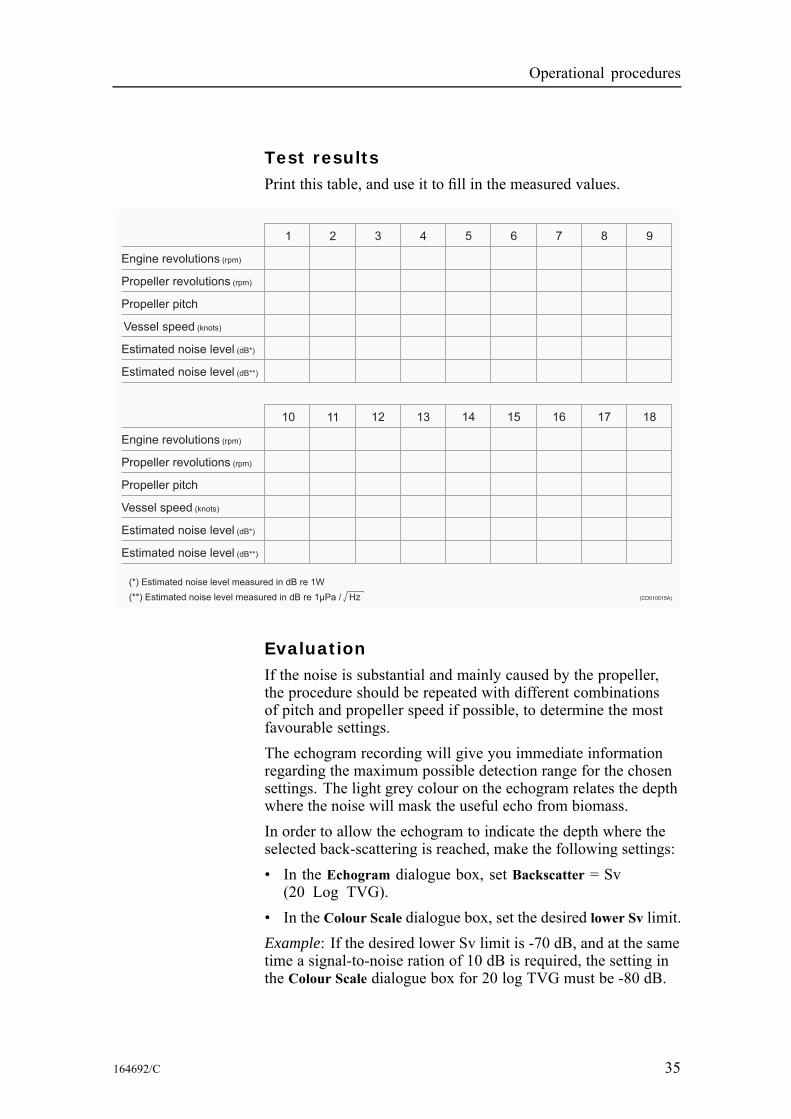
Test resultsPrint this table, and use it to fill in the measured values.
Engine revolutions (rpm)
1 2 3 4 5 6 7 8 9
Propeller revolutions (rpm)
Propeller pitch
(knots)Vessel speed
Estimated noise level (dB*)
Estimated noise level (dB**)
Engine revolutions (rpm)
10 11 12 13 14 15 16 17 18
Propeller revolutions (rpm)
Propeller pitch
Vessel speed (knots)
Estimated noise level (dB*)
(*) Estimated noise level measured in dB re 1W
(**) measured in dB re 1 Pa / HzμEstimated noise level
Estimated noise level (dB**)
(CD010015A)
EvaluationIf the noise is substantial and mainly caused by the propeller,the procedure should be repeated with different combinationsof pitch and propeller speed if possible, to determine the mostfavourable settings.The echogram recording will give you immediate informationregarding the maximum possible detection range for the chosensettings. The light grey colour on the echogram relates the depthwhere the noise will mask the useful echo from biomass.In order to allow the echogram to indicate the depth where theselected back-scattering is reached, make the following settings:• In the Echogram dialogue box, set Backscatter = Sv(20 Log TVG).
• In the Colour Scale dialogue box, set the desired lower Sv limit.Example: If the desired lower Sv limit is -70 dB, and at the sametime a signal-to-noise ration of 10 dB is required, the setting inthe Colour Scale dialogue box for 20 log TVG must be -80 dB.
164692/C 35
Simrad ER60
The depth where the light grey colour appears on the echogramthen indicates the maximum depth where the desired Sv limit isobtained with a signal-to-noise ratio of 10 dB.When you select Backscatter = Sp (40 log TVG) in the Echogramdialogue to record single object target strength, the desired lowerTS limit has to be set in the same way as above.Example: If the desired lower TS limit is -50 dB, and at the sametime a signal-to-noise ratio of 10 dB is required, the setting in theColour Scale dialogue box for 40 log TVG must be -60 dB. Thedepth where the light grey colour appears on the echogram thenindicates the maximum depth where the desired lower TS limit isobtained with a signal-to-noise ratio of 10 dB.
36 164692/C
Operational procedures
Multiplexer set-upUse the following procedures to connect the multiplexer unit tothe echo sounder transceiver, and to enable it for operational use.Technical information on page 38
Related topics
Transceiver Installation on page 156
How to connect the multiplexerThe multiplexer unit consists of a single metal box with twocables. Both cables are terminated with plugs. Observe thefollowing procedure.1 Switch off the echo sounder system.2 Connect the cable with the transducer plug to the transducer
socket on the echo sounder transceiver.3 Connect the cable with the D-Connector to the Auxiliary
socket on the echo sounder transceiver.4 Makes sure that the two transducers are properly connected
to the multiplexer unit.5 Power up the echo sounder system.
How to set up the transceiverIn order to put the multiplexer to use, observe the followingprocedure.1 Start up the echo sounder.2 Click Install→Transceiver, and observe that the Transceiver
Installation dialogue opens.3 Click to select a valid frequency channel, and make sure that
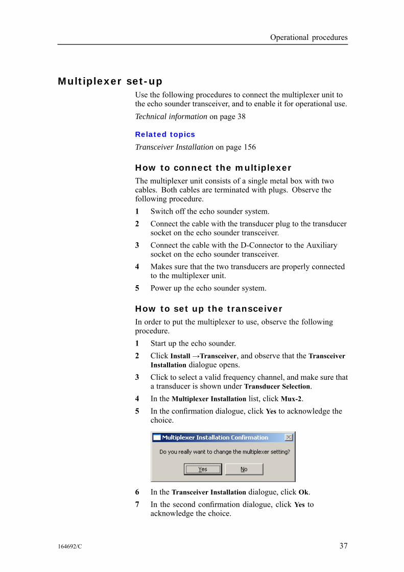
a transducer is shown under Transducer Selection.4 In the Multiplexer Installation list, click Mux-2.5 In the confirmation dialogue, click Yes to acknowledge the
choice.
6 In the Transceiver Installation dialogue, click Ok.7 In the second confirmation dialogue, click Yes to
acknowledge the choice.
164692/C 37
Simrad ER60
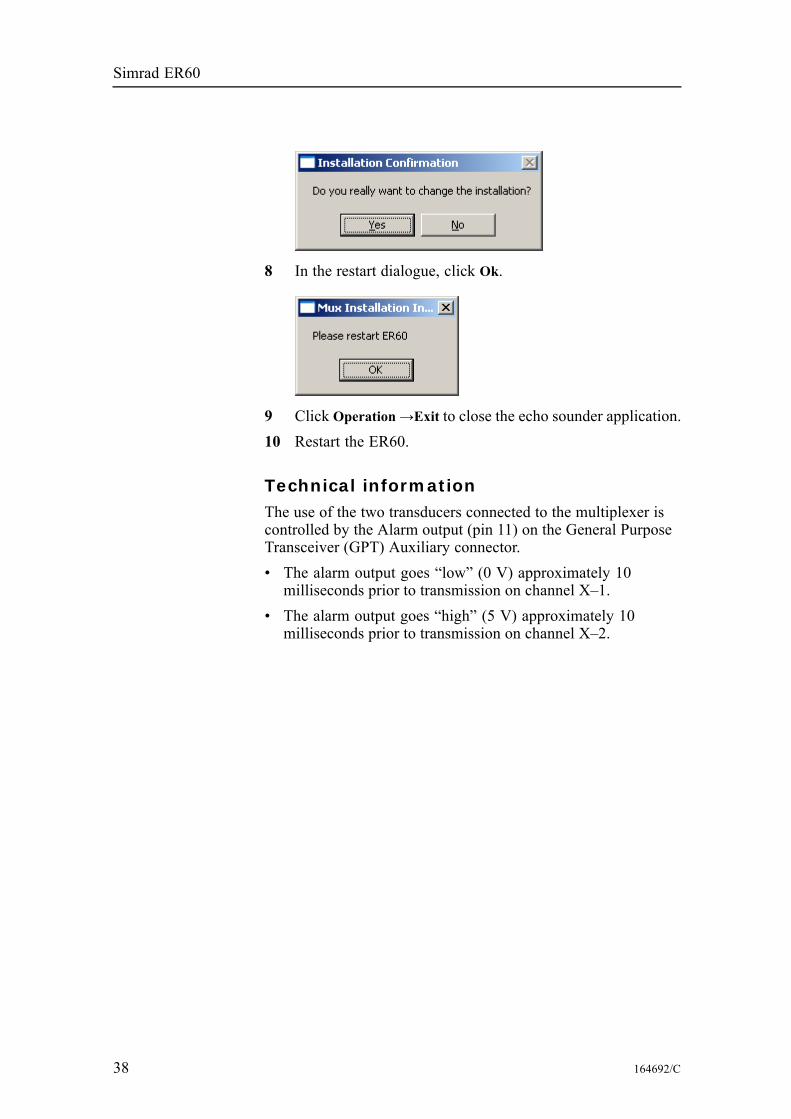
8 In the restart dialogue, click Ok.
9 Click Operation→Exit to close the echo sounder application.10 Restart the ER60.
Technical informationThe use of the two transducers connected to the multiplexer iscontrolled by the Alarm output (pin 11) on the General PurposeTransceiver (GPT) Auxiliary connector.• The alarm output goes “low” (0 V) approximately 10milliseconds prior to transmission on channel X–1.
• The alarm output goes “high” (5 V) approximately 10milliseconds prior to transmission on channel X–2.
38 164692/C

Display views
DISPLAY VIEWSThis chapter provides a brief overview of the informationdisplayed by the Simrad ER60, and how it is organised.
Topics
Display organisation on page 40Main menu on page 41Toolbar on page 42Status bar on page 43Channel windows on page 44
164692/C 39
Simrad ER60
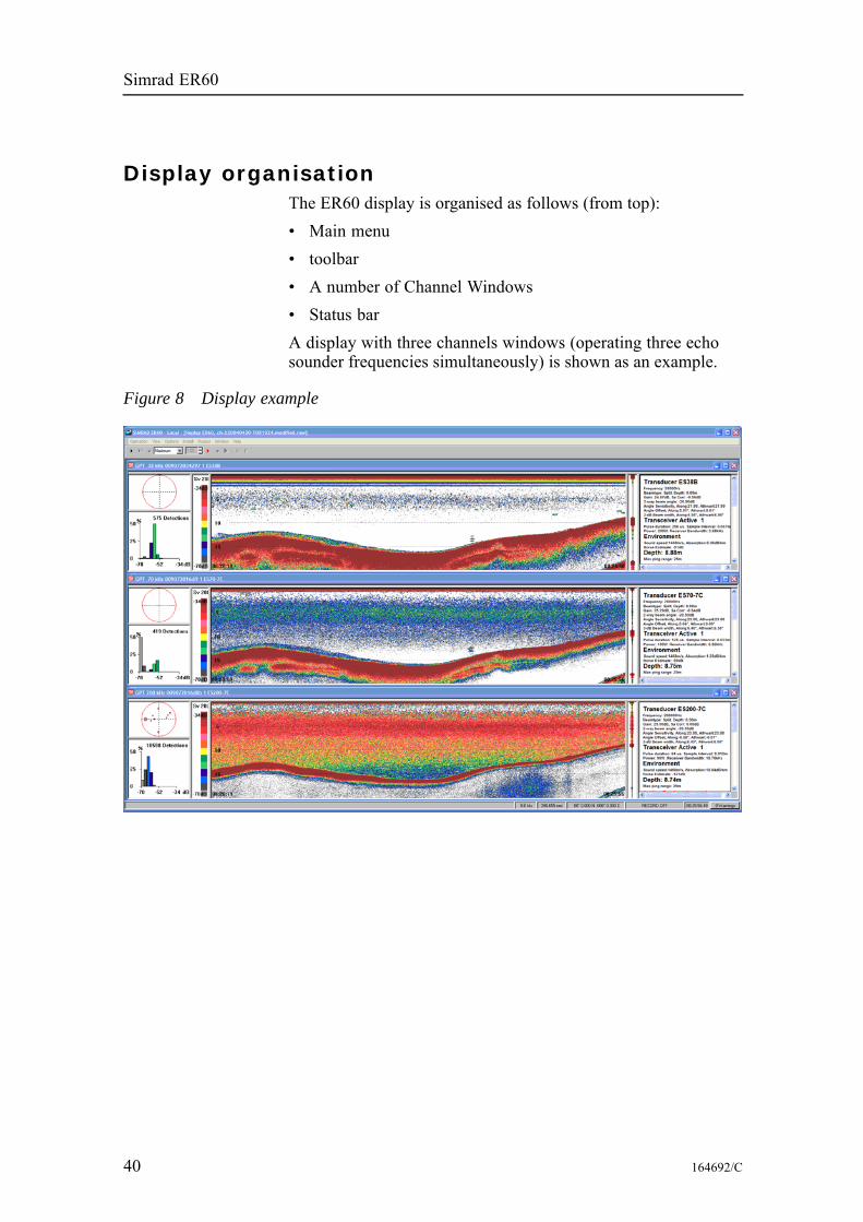
Display organisationThe ER60 display is organised as follows (from top):• Main menu• toolbar• A number of Channel Windows• Status barA display with three channels windows (operating three echosounder frequencies simultaneously) is shown as an example.
Figure 8 Display example
40 164692/C
Display views
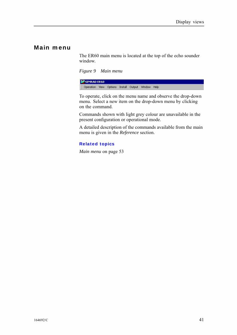
Main menuThe ER60 main menu is located at the top of the echo sounderwindow.
Figure 9 Main menu
To operate, click on the menu name and observe the drop-downmenu. Select a new item on the drop-down menu by clickingon the command.Commands shown with light grey colour are unavailable in thepresent configuration or operational mode.A detailed description of the commands available from the mainmenu is given in the Reference section.
Related topics
Main menu on page 53
164692/C 41
Simrad ER60
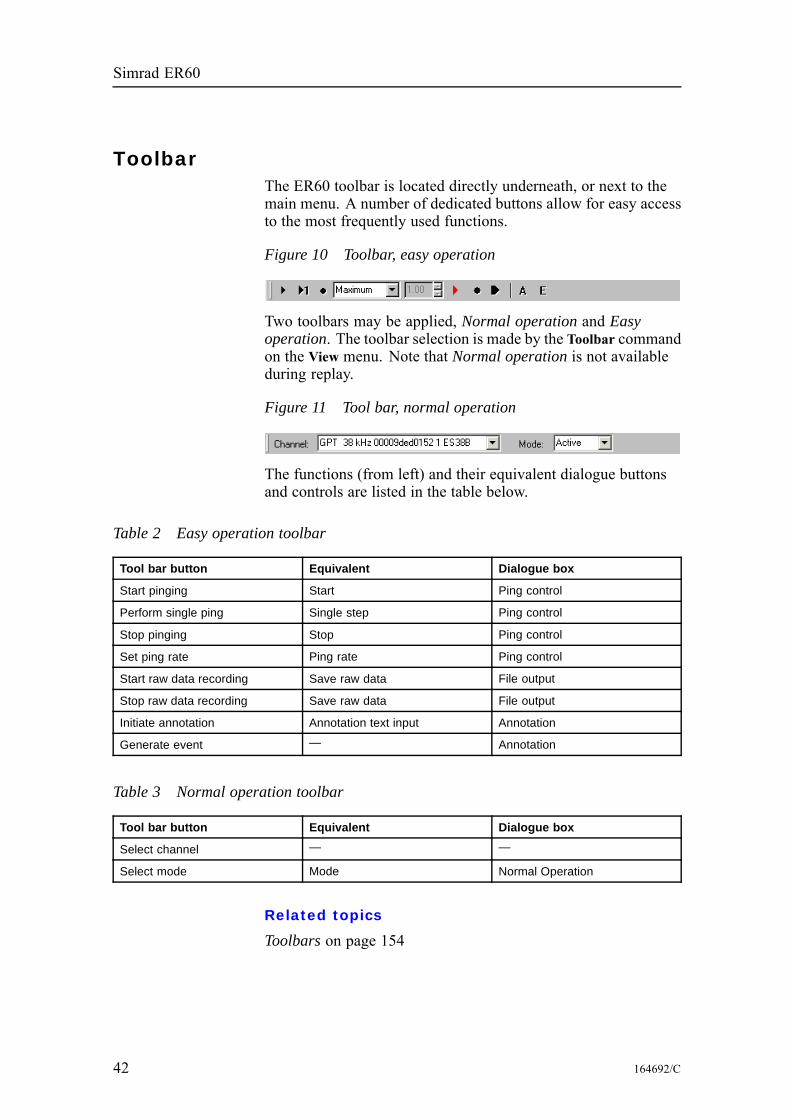
ToolbarThe ER60 toolbar is located directly underneath, or next to themain menu. A number of dedicated buttons allow for easy accessto the most frequently used functions.
Figure 10 Toolbar, easy operation
Two toolbars may be applied, Normal operation and Easyoperation. The toolbar selection is made by the Toolbar commandon the View menu. Note that Normal operation is not availableduring replay.
Figure 11 Tool bar, normal operation
The functions (from left) and their equivalent dialogue buttonsand controls are listed in the table below.
Table 2 Easy operation toolbar
Tool bar button Equivalent Dialogue box
Start pinging Start Ping control
Perform single ping Single step Ping control
Stop pinging Stop Ping control
Set ping rate Ping rate Ping control
Start raw data recording Save raw data File output
Stop raw data recording Save raw data File output
Initiate annotation Annotation text input Annotation
Generate event — Annotation
Table 3 Normal operation toolbar
Tool bar button Equivalent Dialogue box
Select channel — —
Select mode Mode Normal Operation
Related topics
Toolbars on page 154
42 164692/C
Display views
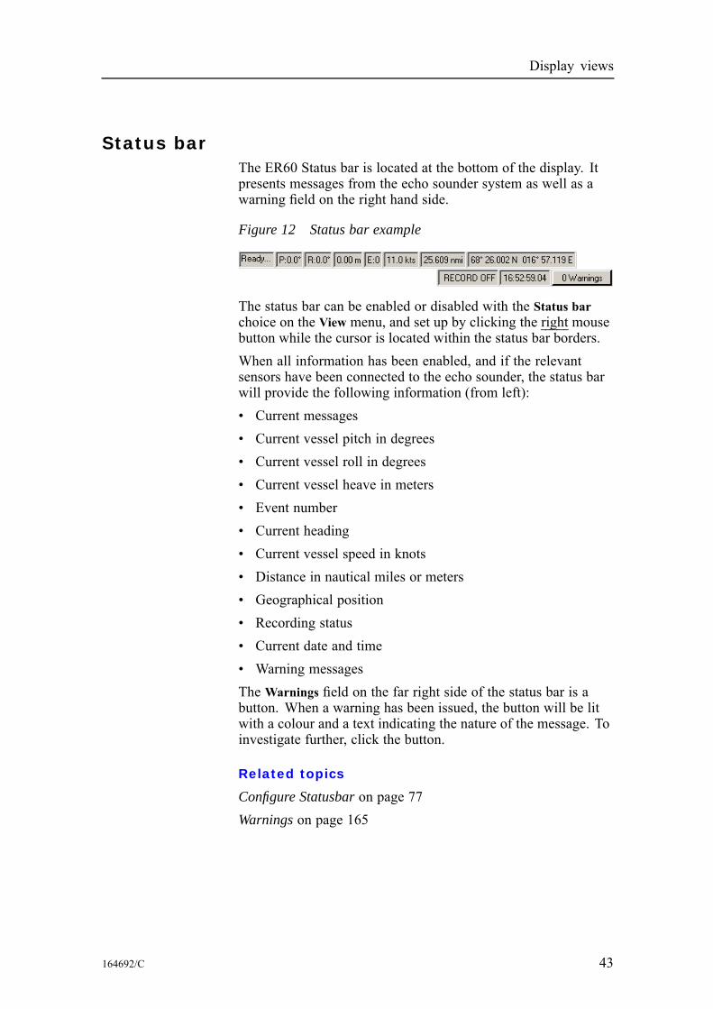
Status barThe ER60 Status bar is located at the bottom of the display. Itpresents messages from the echo sounder system as well as awarning field on the right hand side.
Figure 12 Status bar example
The status bar can be enabled or disabled with the Status barchoice on the View menu, and set up by clicking the right mousebutton while the cursor is located within the status bar borders.When all information has been enabled, and if the relevantsensors have been connected to the echo sounder, the status barwill provide the following information (from left):• Current messages• Current vessel pitch in degrees• Current vessel roll in degrees• Current vessel heave in meters• Event number• Current heading• Current vessel speed in knots• Distance in nautical miles or meters• Geographical position• Recording status• Current date and time• Warning messagesThe Warnings field on the far right side of the status bar is abutton. When a warning has been issued, the button will be litwith a colour and a text indicating the nature of the message. Toinvestigate further, click the button.
Related topics
Configure Statusbar on page 77Warnings on page 165
164692/C 43
Simrad ER60
Channel windowsThe ER60 channel window is the main information bearer onthe echo sounder display. One channel window is provided foreach operational frequency, and you can have many channelwindows open simultaneously. Each channel window containsthe following views:Depth view on page 45Single target position view on page 46Single target histogram view on page 47Echogram view on page 48Scope view on page 49Colour scale view on page 50Numerical view on page 51
44 164692/C
Display views
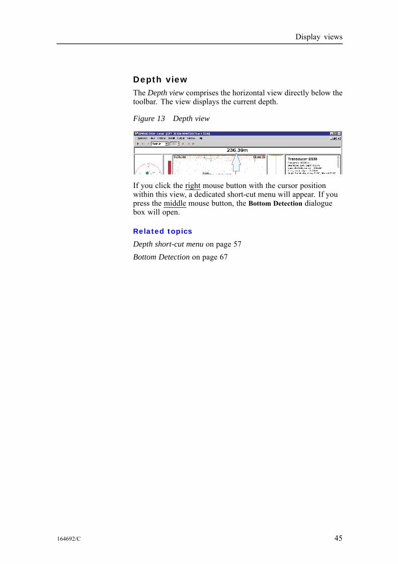
Depth viewThe Depth view comprises the horizontal view directly below thetoolbar. The view displays the current depth.
Figure 13 Depth view
(CD
010012B
)
If you click the right mouse button with the cursor positionwithin this view, a dedicated short-cut menu will appear. If youpress the middle mouse button, the Bottom Detection dialoguebox will open.
Related topics
Depth short-cut menu on page 57Bottom Detection on page 67
164692/C 45
Simrad ER60
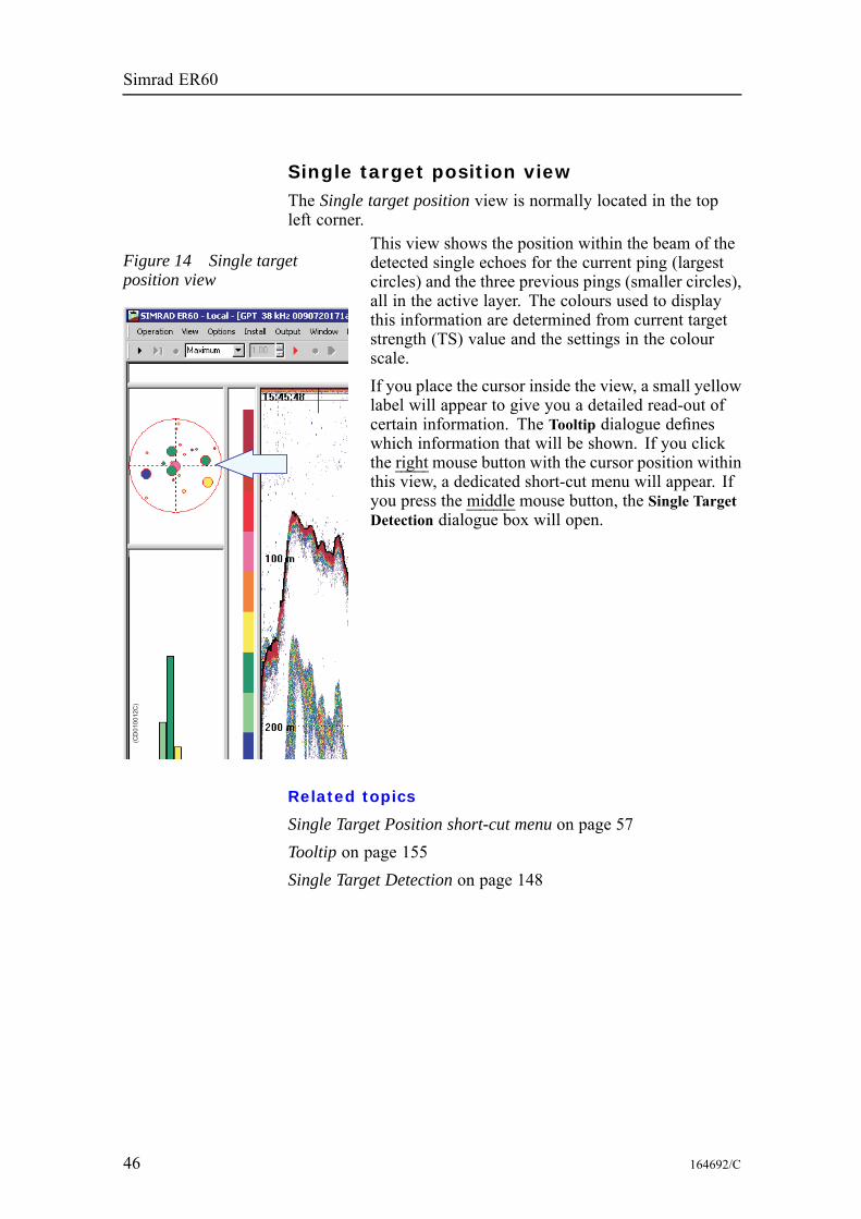
Single target position viewThe Single target position view is normally located in the topleft corner.
Figure 14 Single targetposition view
(CD
010012C
)
This view shows the position within the beam of thedetected single echoes for the current ping (largestcircles) and the three previous pings (smaller circles),all in the active layer. The colours used to displaythis information are determined from current targetstrength (TS) value and the settings in the colourscale.If you place the cursor inside the view, a small yellowlabel will appear to give you a detailed read-out ofcertain information. The Tooltip dialogue defineswhich information that will be shown. If you clickthe right mouse button with the cursor position withinthis view, a dedicated short-cut menu will appear. Ifyou press the middle mouse button, the Single TargetDetection dialogue box will open.
Related topics
Single Target Position short-cut menu on page 57Tooltip on page 155Single Target Detection on page 148
46 164692/C
Display views
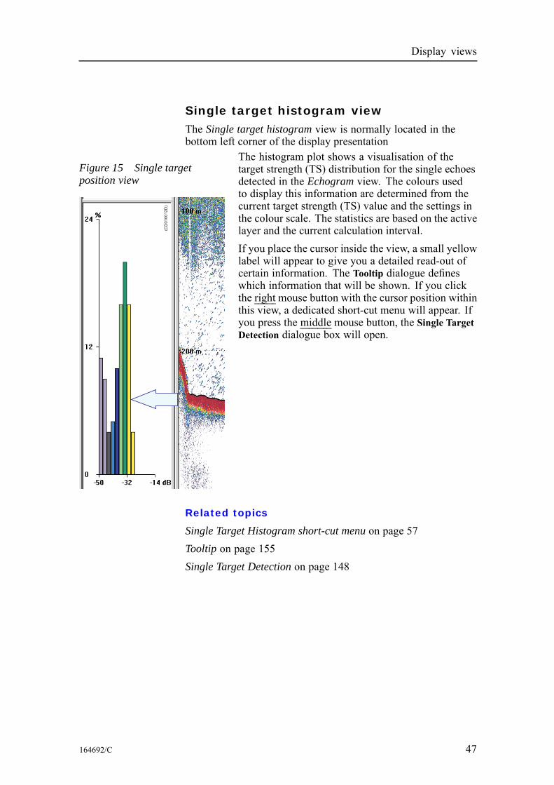
Single target histogram viewThe Single target histogram view is normally located in thebottom left corner of the display presentation
Figure 15 Single targetposition view
(CD
010012D
)
The histogram plot shows a visualisation of thetarget strength (TS) distribution for the single echoesdetected in the Echogram view. The colours usedto display this information are determined from thecurrent target strength (TS) value and the settings inthe colour scale. The statistics are based on the activelayer and the current calculation interval.If you place the cursor inside the view, a small yellowlabel will appear to give you a detailed read-out ofcertain information. The Tooltip dialogue defineswhich information that will be shown. If you clickthe right mouse button with the cursor position withinthis view, a dedicated short-cut menu will appear. Ifyou press the middle mouse button, the Single TargetDetection dialogue box will open.
Related topics
Single Target Histogram short-cut menu on page 57Tooltip on page 155Single Target Detection on page 148
164692/C 47
Simrad ER60
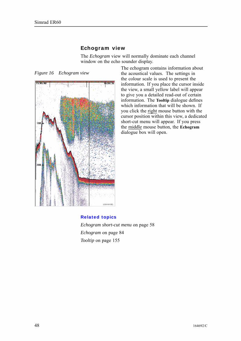
Echogram viewThe Echogram view will normally dominate each channelwindow on the echo sounder display.
Figure 16 Echogram view
(CD010012E)
The echogram contains information aboutthe acoustical values. The settings inthe colour scale is used to present theinformation. If you place the cursor insidethe view, a small yellow label will appearto give you a detailed read-out of certaininformation. The Tooltip dialogue defineswhich information that will be shown. Ifyou click the right mouse button with thecursor position within this view, a dedicatedshort-cut menu will appear. If you pressthe middle mouse button, the Echogramdialogue box will open.
Related topics
Echogram short-cut menu on page 58Echogram on page 84Tooltip on page 155
48 164692/C
Display views
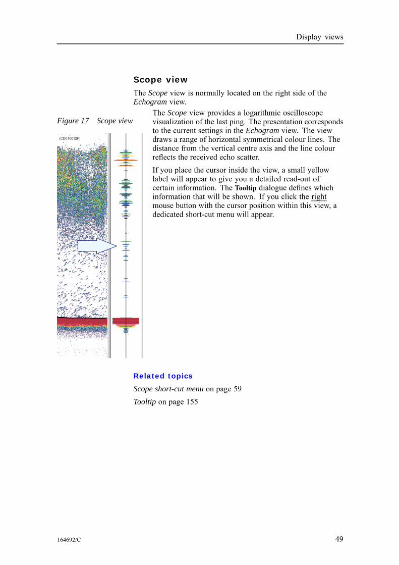
Scope viewThe Scope view is normally located on the right side of theEchogram view.
Figure 17 Scope view
(CD010012F)
The Scope view provides a logarithmic oscilloscopevisualization of the last ping. The presentation correspondsto the current settings in the Echogram view. The viewdraws a range of horizontal symmetrical colour lines. Thedistance from the vertical centre axis and the line colourreflects the received echo scatter.If you place the cursor inside the view, a small yellowlabel will appear to give you a detailed read-out ofcertain information. The Tooltip dialogue defines whichinformation that will be shown. If you click the rightmouse button with the cursor position within this view, adedicated short-cut menu will appear.
Related topics
Scope short-cut menu on page 59Tooltip on page 155
164692/C 49
Simrad ER60
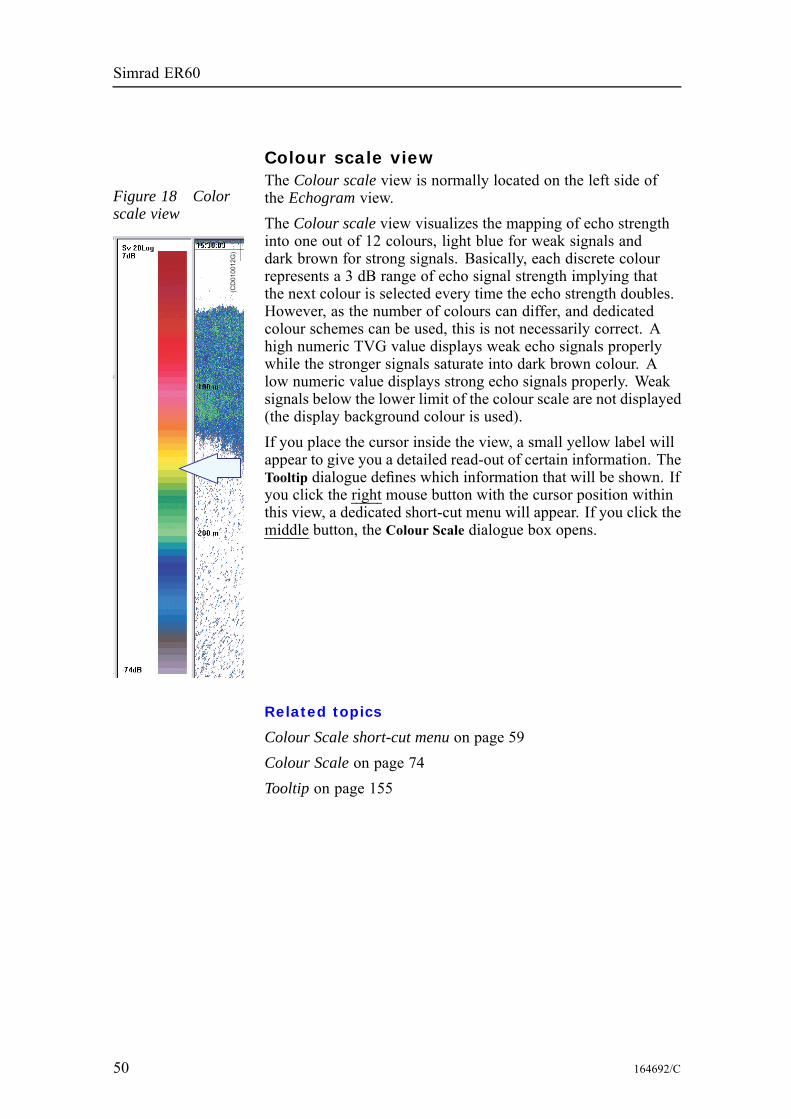
Colour scale view
Figure 18 Colorscale view
(CD
01
00
12
G)
The Colour scale view is normally located on the left side ofthe Echogram view.The Colour scale view visualizes the mapping of echo strengthinto one out of 12 colours, light blue for weak signals anddark brown for strong signals. Basically, each discrete colourrepresents a 3 dB range of echo signal strength implying thatthe next colour is selected every time the echo strength doubles.However, as the number of colours can differ, and dedicatedcolour schemes can be used, this is not necessarily correct. Ahigh numeric TVG value displays weak echo signals properlywhile the stronger signals saturate into dark brown colour. Alow numeric value displays strong echo signals properly. Weaksignals below the lower limit of the colour scale are not displayed(the display background colour is used).If you place the cursor inside the view, a small yellow label willappear to give you a detailed read-out of certain information. TheTooltip dialogue defines which information that will be shown. Ifyou click the right mouse button with the cursor position withinthis view, a dedicated short-cut menu will appear. If you click themiddle button, the Colour Scale dialogue box opens.
Related topics
Colour Scale short-cut menu on page 59Colour Scale on page 74Tooltip on page 155
50 164692/C
Display views
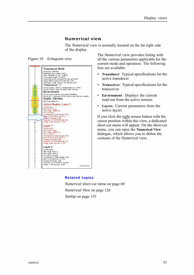
Numerical viewThe Numerical view is normally located on the far right sideof the display.
Figure 19 Echogram view
(CD010012H)
The Numerical view provides listing withall the various parameters applicable for thecurrent mode and operation. The followinglists are available:• Transducer: Typical specifications for theactive transducer
• Transceiver: Typical specifications for thetransceiver
• Environment: Displays the currentread-out from the active sensors
• Layers: Current parameters from theactive layers
If you click the right mouse button with thecursor position within this view, a dedicatedshort-cut menu will appear. On the short-cutmenu, you can open the Numerical Viewdialogue, which allows you to define thecontents of the Numerical view.
Related topics
Numerical short-cut menu on page 60Numerical View on page 126Tooltip on page 155
164692/C 51
Simrad ER60
MENU SYSTEMMenu navigation employed by the Simrad ER60 Scientific echosounder is similar to other Windows-based software. Main menutopics located in the menu bar at the top of the window provideaccess to drop-down menus. Menu choices that are shown in greyare not available for the current operation or operational mode.Several parameters are also available using short-cut menusaccessed by clicking the right mouse button. For more specificmenu information refer to the menu descriptions listed below.
Topics
Main menu on page 53Short-cut menus on page 57
52 164692/C
Menu system
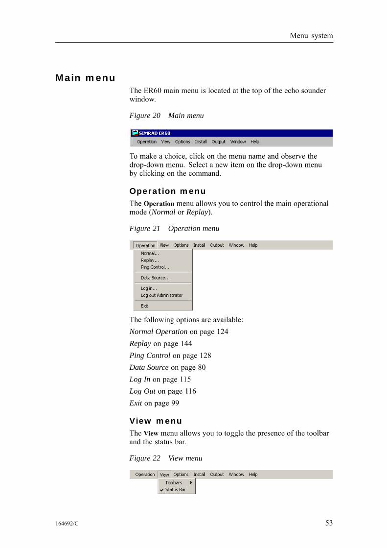
Main menuThe ER60 main menu is located at the top of the echo sounderwindow.
Figure 20 Main menu
To make a choice, click on the menu name and observe thedrop-down menu. Select a new item on the drop-down menuby clicking on the command.
Operation menuThe Operation menu allows you to control the main operationalmode (Normal or Replay).
Figure 21 Operation menu
The following options are available:Normal Operation on page 124Replay on page 144Ping Control on page 128Data Source on page 80Log In on page 115Log Out on page 116Exit on page 99
View menuThe View menu allows you to toggle the presence of the toolbarand the status bar.
Figure 22 View menu
164692/C 53
Simrad ER60
The following options are available:Toolbars on page 154Status bar on page 150
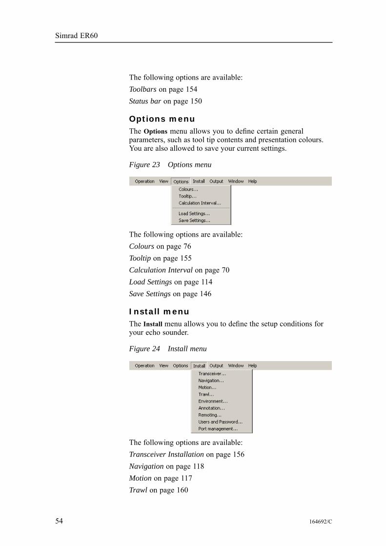
Options menuThe Options menu allows you to define certain generalparameters, such as tool tip contents and presentation colours.You are also allowed to save your current settings.
Figure 23 Options menu
The following options are available:Colours on page 76Tooltip on page 155Calculation Interval on page 70Load Settings on page 114Save Settings on page 146
Install menuThe Install menu allows you to define the setup conditions foryour echo sounder.
Figure 24 Install menu
The following options are available:Transceiver Installation on page 156Navigation on page 118Motion on page 117Trawl on page 160
54 164692/C
Menu system
Environment on page 94Annotation on page 65Remoting on page 139Users and Passwords on page 163Port Management on page 130
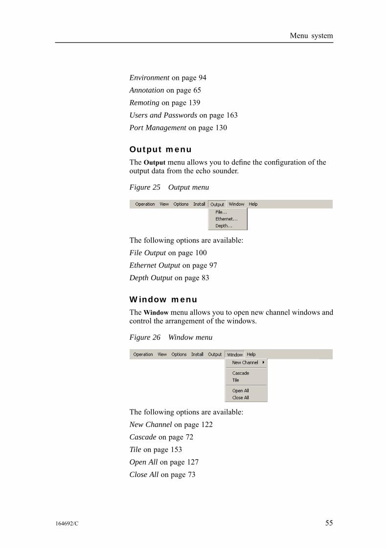
Output menuThe Output menu allows you to define the configuration of theoutput data from the echo sounder.
Figure 25 Output menu
The following options are available:File Output on page 100Ethernet Output on page 97Depth Output on page 83
Window menuTheWindow menu allows you to open new channel windows andcontrol the arrangement of the windows.
Figure 26 Window menu
The following options are available:New Channel on page 122Cascade on page 72Tile on page 153Open All on page 127Close All on page 73
164692/C 55
Simrad ER60
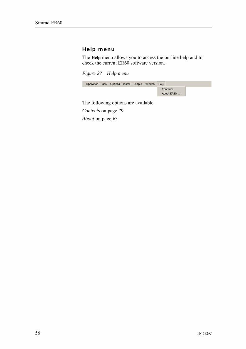
Help menuThe Help menu allows you to access the on-line help and tocheck the current ER60 software version.
Figure 27 Help menu
The following options are available:Contents on page 79About on page 63
56 164692/C
Menu system
Short-cut menusThe short-cut menus are accessed with the right mouse buttonwhen the cursor is located in any of the views. Various menusare provided depending on the current view. To make a choice,click on the menu name and observe the drop-down menu. Selecta new item on the drop-down menu by clicking on the command.
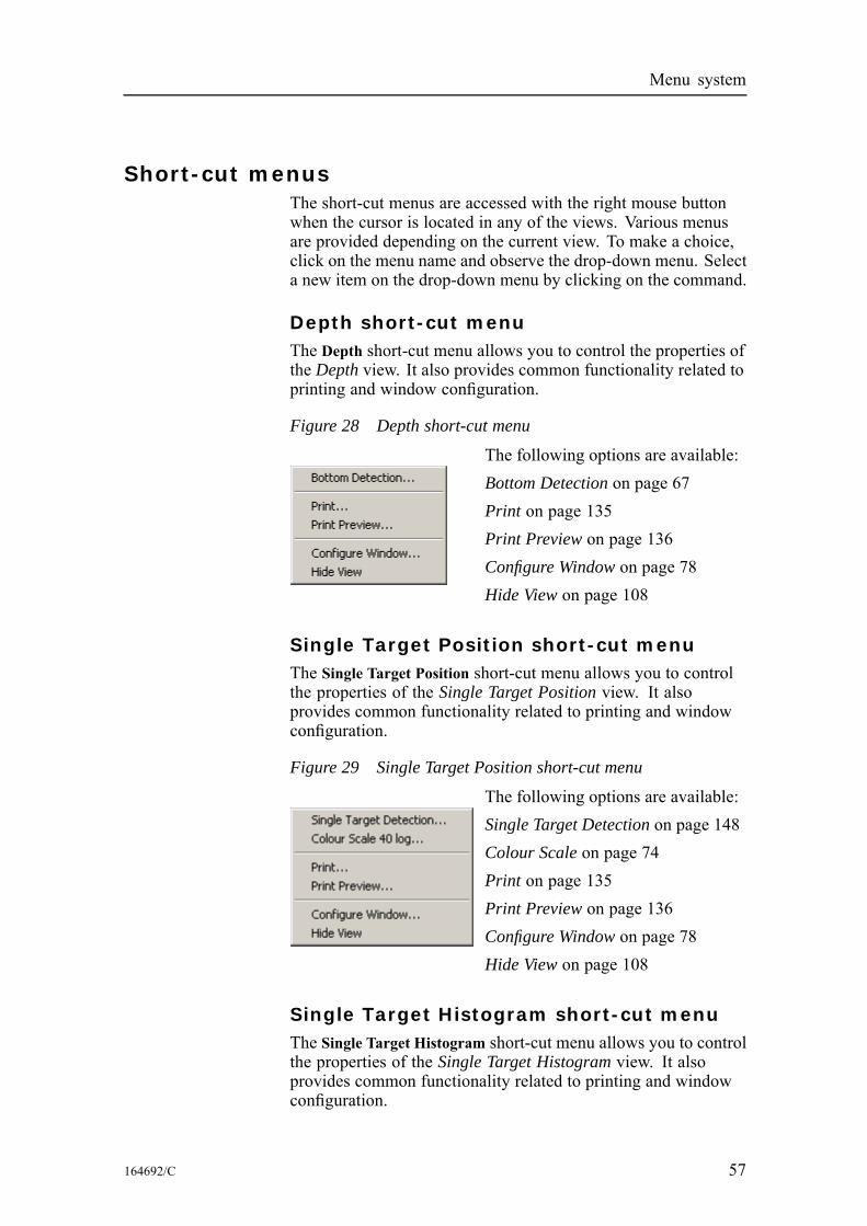
Depth short-cut menuThe Depth short-cut menu allows you to control the properties ofthe Depth view. It also provides common functionality related toprinting and window configuration.
Figure 28 Depth short-cut menu
The following options are available:Bottom Detection on page 67Print on page 135Print Preview on page 136Configure Window on page 78Hide View on page 108
Single Target Position short-cut menuThe Single Target Position short-cut menu allows you to controlthe properties of the Single Target Position view. It alsoprovides common functionality related to printing and windowconfiguration.
Figure 29 Single Target Position short-cut menu
The following options are available:Single Target Detection on page 148Colour Scale on page 74Print on page 135Print Preview on page 136Configure Window on page 78Hide View on page 108
Single Target Histogram short-cut menuThe Single Target Histogram short-cut menu allows you to controlthe properties of the Single Target Histogram view. It alsoprovides common functionality related to printing and windowconfiguration.
164692/C 57
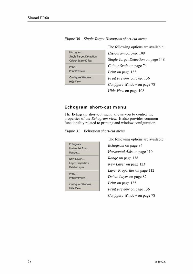
Simrad ER60
Figure 30 Single Target Histogram short-cut menu
The following options are available:Histogram on page 109Single Target Detection on page 148Colour Scale on page 74Print on page 135Print Preview on page 136Configure Window on page 78Hide View on page 108
Echogram short-cut menu
The Echogram short-cut menu allows you to control theproperties of the Echogram view. It also provides commonfunctionality related to printing and window configuration.
Figure 31 Echogram short-cut menu
The following options are available:Echogram on page 84Horizontal Axis on page 110Range on page 138New Layer on page 123Layer Properties on page 112Delete Layer on page 82Print on page 135Print Preview on page 136Configure Window on page 78
58 164692/C
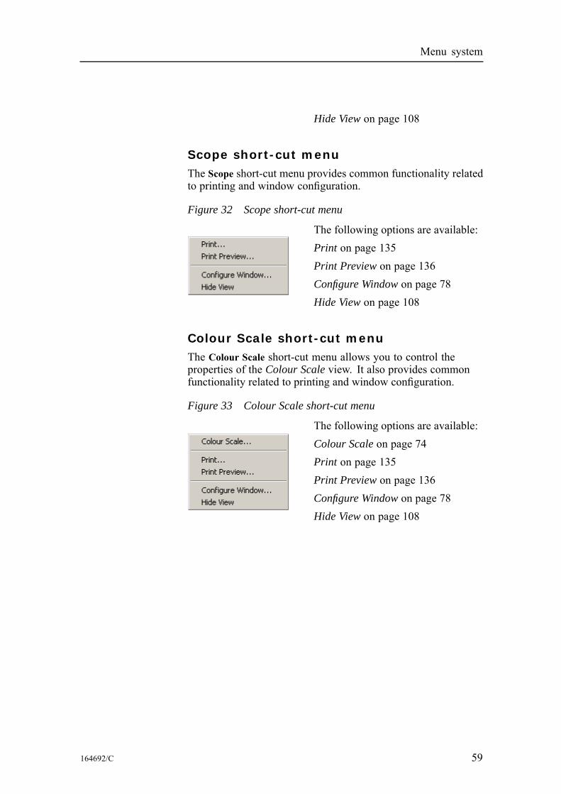
Menu system
Hide View on page 108
Scope short-cut menuThe Scope short-cut menu provides common functionality relatedto printing and window configuration.
Figure 32 Scope short-cut menu
The following options are available:Print on page 135Print Preview on page 136Configure Window on page 78Hide View on page 108
Colour Scale short-cut menuThe Colour Scale short-cut menu allows you to control theproperties of the Colour Scale view. It also provides commonfunctionality related to printing and window configuration.
Figure 33 Colour Scale short-cut menu
The following options are available:Colour Scale on page 74Print on page 135Print Preview on page 136Configure Window on page 78Hide View on page 108
164692/C 59
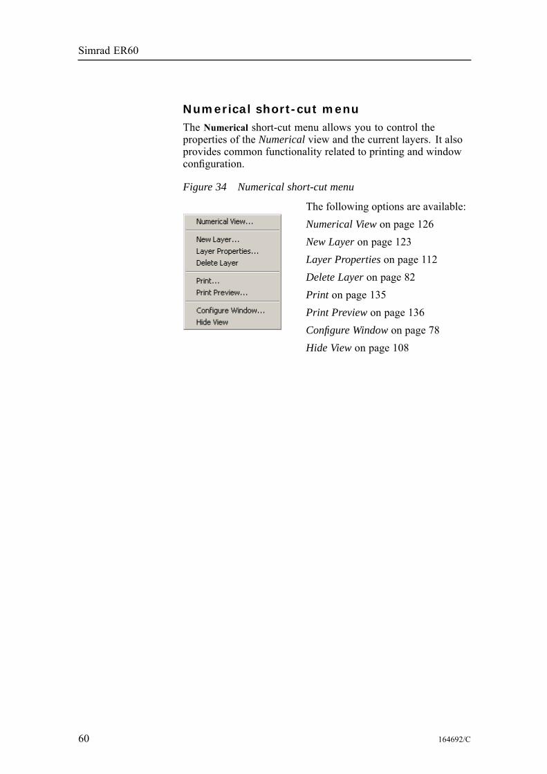
Simrad ER60
Numerical short-cut menuThe Numerical short-cut menu allows you to control theproperties of the Numerical view and the current layers. It alsoprovides common functionality related to printing and windowconfiguration.
Figure 34 Numerical short-cut menu
The following options are available:Numerical View on page 126New Layer on page 123Layer Properties on page 112Delete Layer on page 82Print on page 135Print Preview on page 136Configure Window on page 78Hide View on page 108
60 164692/C

References
REFERENCESThis chapter contains reference information about dialogue boxesand parameters.
Topics
Alphabetical list of dialogue boxes and functions on page 61Dialogue box and functions descriptions on page 63
Alphabetical list of dialogue boxes and functionsThis section provides an alphabetical list of all the dialogueboxes.About on page 63Add User Account on page 64Annotation on page 65Bottom Detection on page 67Bottom Range on page 69Calculation Interval on page 70Cascade on page 72Close All on page 73Colour Scale on page 74Colours on page 76Configure Statusbar on page 77Configure Window on page 78Contents on page 79Data Source on page 80Delete Layer on page 82Depth Output on page 83Echogram on page 84EK500 Datagram on page 90Environment on page 94Errors on page 96Ethernet Output on page 97Exit on page 99File Output on page 100HAC Datagram on page 106Hide View on page 108Histogram on page 109
164692/C 61
Simrad ER60
Horizontal Axis on page 110LAN Port Setup on page 111Layer Properties on page 112Load Settings on page 114Log In on page 115Log Out on page 116Motion on page 117Navigation on page 118New Channel on page 122New Layer on page 123Normal Operation on page 124Numerical View on page 126Open All on page 127Ping Control on page 128Port Management on page 130Port Monitor on page 133Print on page 135Print Preview on page 136Remoting on page 139Replay on page 144Save Settings on page 146Serial Port Setup on page 147Single Target Detection on page 148Status bar on page 150Surface Range on page 151Tile on page 153Toolbars on page 154Tooltip on page 155Transceiver Installation on page 156Transducer Parameters on page 159Trawl on page 160User Properties on page 162Users and Passwords on page 163Warnings on page 165
62 164692/C
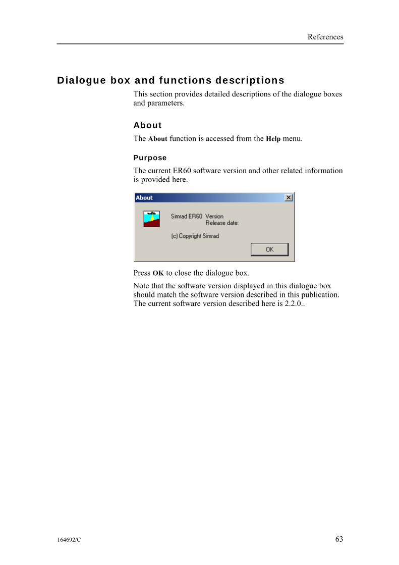
References
Dialogue box and functions descriptionsThis section provides detailed descriptions of the dialogue boxesand parameters.
AboutThe About function is accessed from the Help menu.
Purpose
The current ER60 software version and other related informationis provided here.
Press OK to close the dialogue box.Note that the software version displayed in this dialogue boxshould match the software version described in this publication.The current software version described here is 2.2.0..
164692/C 63
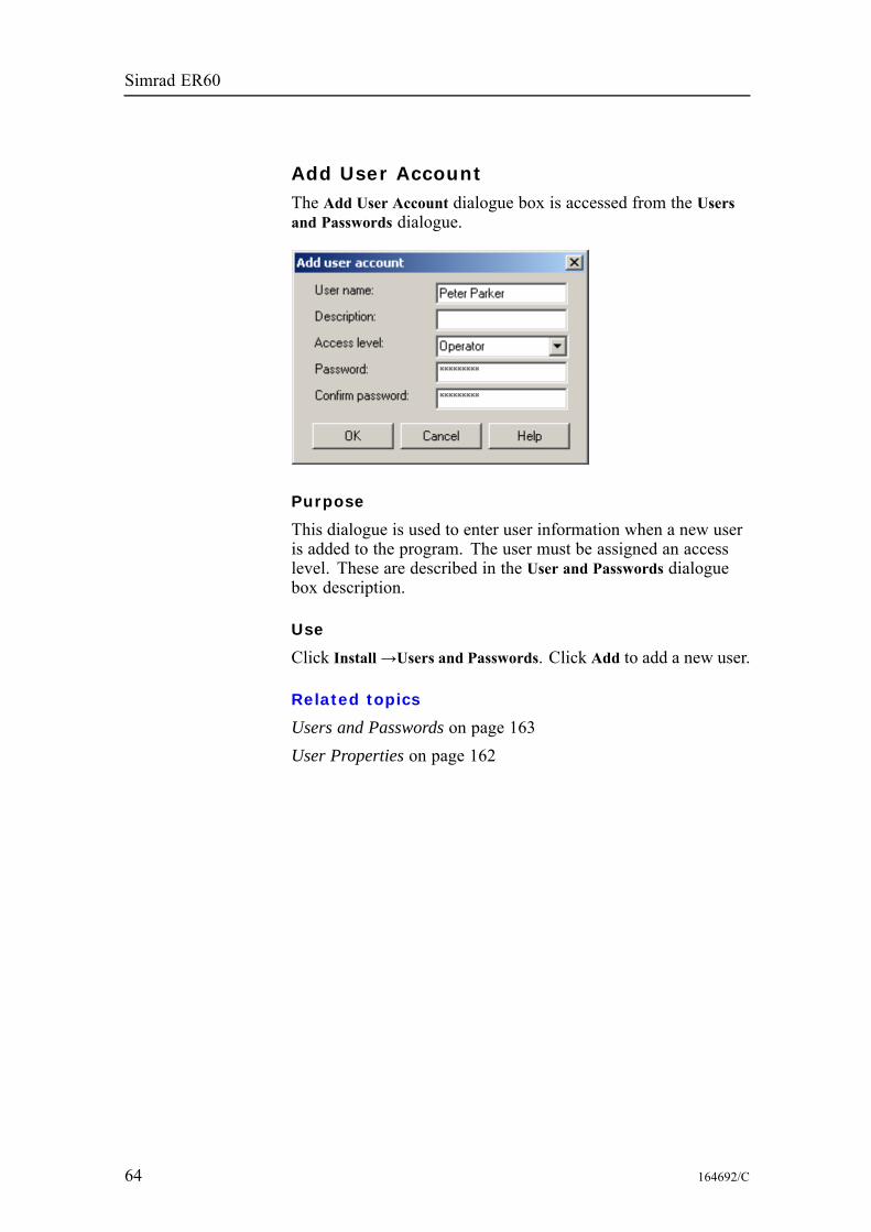
Simrad ER60
Add User AccountThe Add User Account dialogue box is accessed from the Usersand Passwords dialogue.
Purpose
This dialogue is used to enter user information when a new useris added to the program. The user must be assigned an accesslevel. These are described in the User and Passwords dialoguebox description.
Use
Click Install→Users and Passwords. Click Add to add a new user.
Related topics
Users and Passwords on page 163User Properties on page 162
64 164692/C
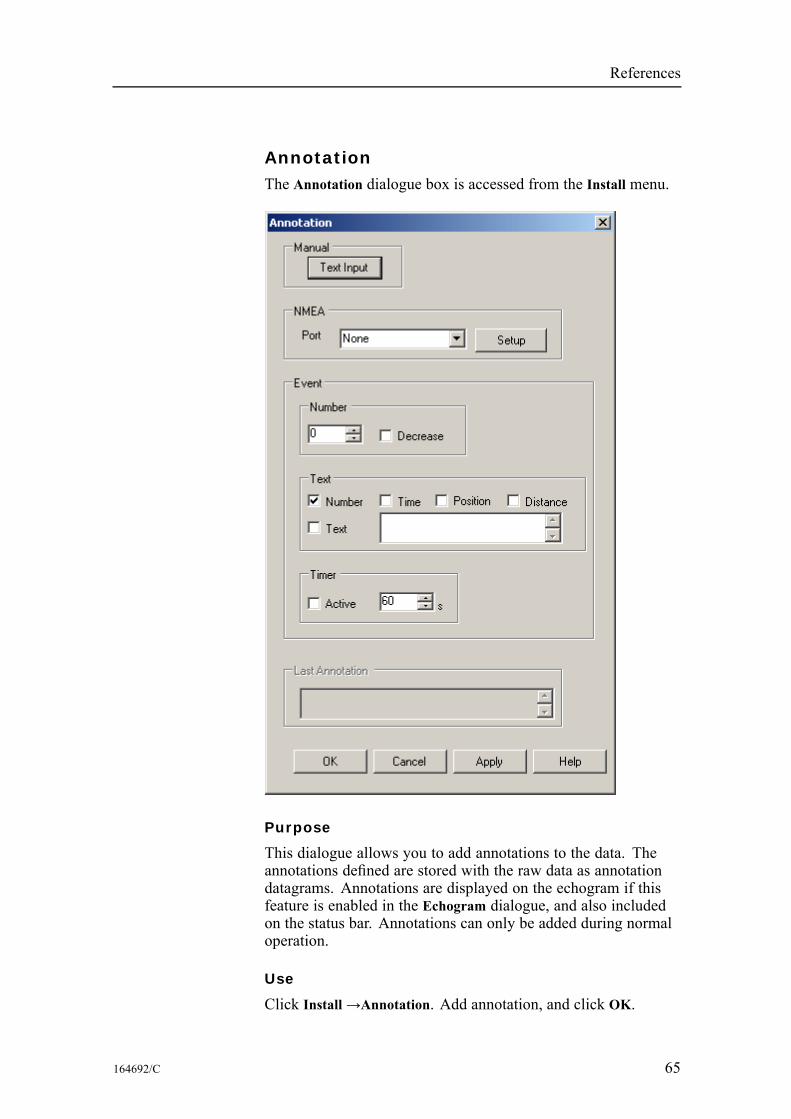
References
AnnotationThe Annotation dialogue box is accessed from the Install menu.
Purpose
This dialogue allows you to add annotations to the data. Theannotations defined are stored with the raw data as annotationdatagrams. Annotations are displayed on the echogram if thisfeature is enabled in the Echogram dialogue, and also includedon the status bar. Annotations can only be added during normaloperation.
Use
Click Install→Annotation. Add annotation, and click OK.
164692/C 65
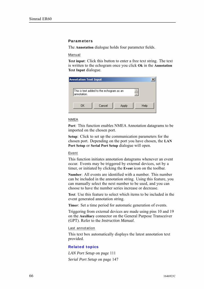
Simrad ER60
Parameters
The Annotation dialogue holds four parameter fields.
Manual
Text input: Click this button to enter a free text string. The textis written to the echogram once you click Ok in the AnnotationText Input dialogue.
NMEA
Port: This function enables NMEA Annotation datagrams to beimported on the chosen port.Setup: Click to set up the communication parameters for thechosen port. Depending on the port you have chosen, the LANPort Setup or Serial Port Setup dialogue will open.
Event
This function initiates annotation datagrams whenever an eventoccur. Events may be triggered by external devices, set by atimer, or initiated by clicking the Event icon on the toolbar.Number: All events are identified with a number. This numbercan be included in the annotation string. Using this feature, youcan manually select the next number to be used, and you canchoose to have the number series increase or decrease.Text: Use this feature to select which items to be included in theevent generated annotation string.Timer: Set a time period for automatic generation of events.Triggering from external devices are made using pins 10 and 19on the Auxiliary connector on the General Purpose Transceiver(GPT). Refer to the Instruction Manual.
Last annotation
This text box automatically displays the latest annotation textprovided.
Related topics
LAN Port Setup on page 111Serial Port Setup on page 147
66 164692/C
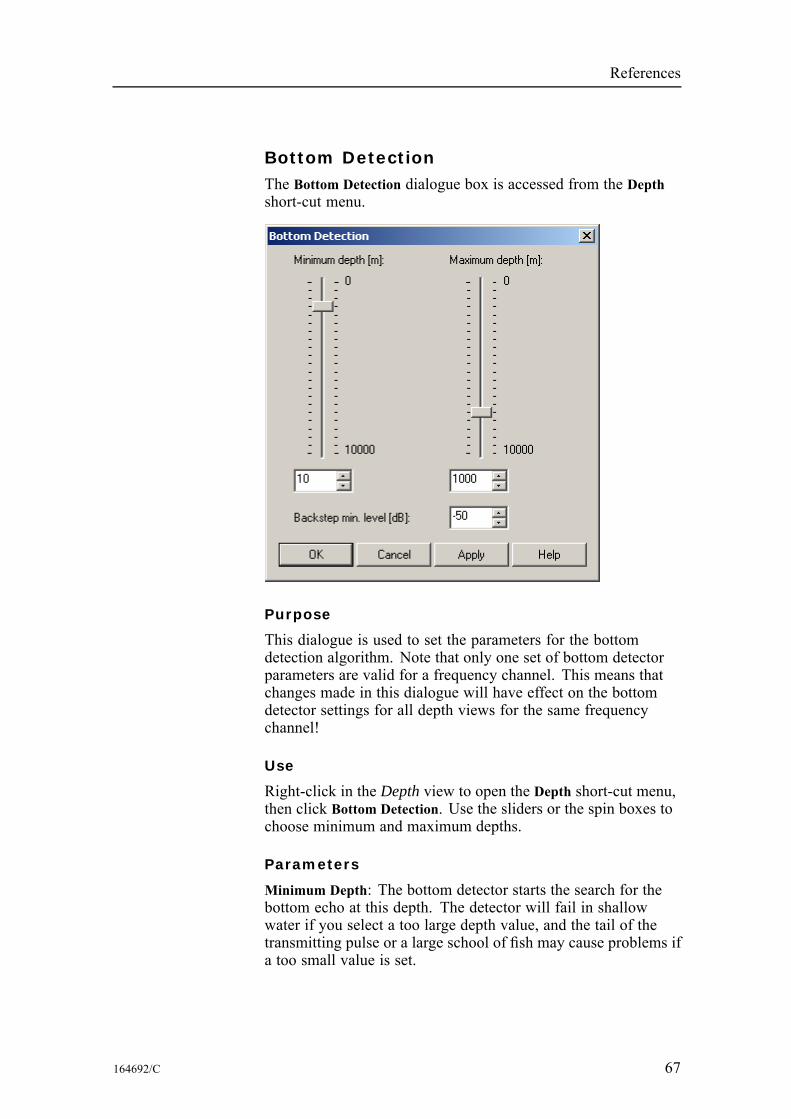
References
Bottom DetectionThe Bottom Detection dialogue box is accessed from the Depthshort-cut menu.
Purpose
This dialogue is used to set the parameters for the bottomdetection algorithm. Note that only one set of bottom detectorparameters are valid for a frequency channel. This means thatchanges made in this dialogue will have effect on the bottomdetector settings for all depth views for the same frequencychannel!
Use
Right-click in the Depth view to open the Depth short-cut menu,then click Bottom Detection. Use the sliders or the spin boxes tochoose minimum and maximum depths.
Parameters
Minimum Depth: The bottom detector starts the search for thebottom echo at this depth. The detector will fail in shallowwater if you select a too large depth value, and the tail of thetransmitting pulse or a large school of fish may cause problems ifa too small value is set.
164692/C 67
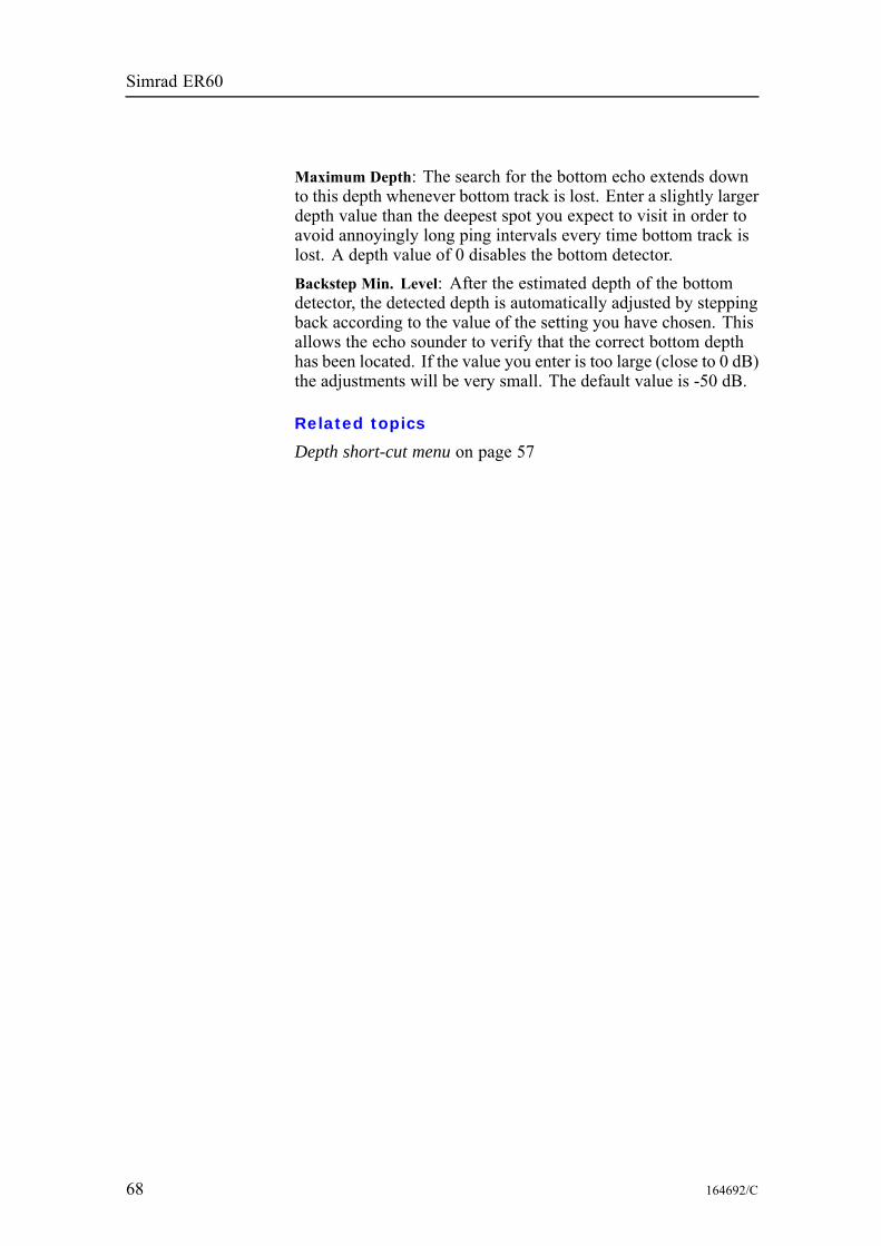
Simrad ER60
Maximum Depth: The search for the bottom echo extends downto this depth whenever bottom track is lost. Enter a slightly largerdepth value than the deepest spot you expect to visit in order toavoid annoyingly long ping intervals every time bottom track islost. A depth value of 0 disables the bottom detector.Backstep Min. Level: After the estimated depth of the bottomdetector, the detected depth is automatically adjusted by steppingback according to the value of the setting you have chosen. Thisallows the echo sounder to verify that the correct bottom depthhas been located. If the value you enter is too large (close to 0 dB)the adjustments will be very small. The default value is -50 dB.
Related topics
Depth short-cut menu on page 57
68 164692/C
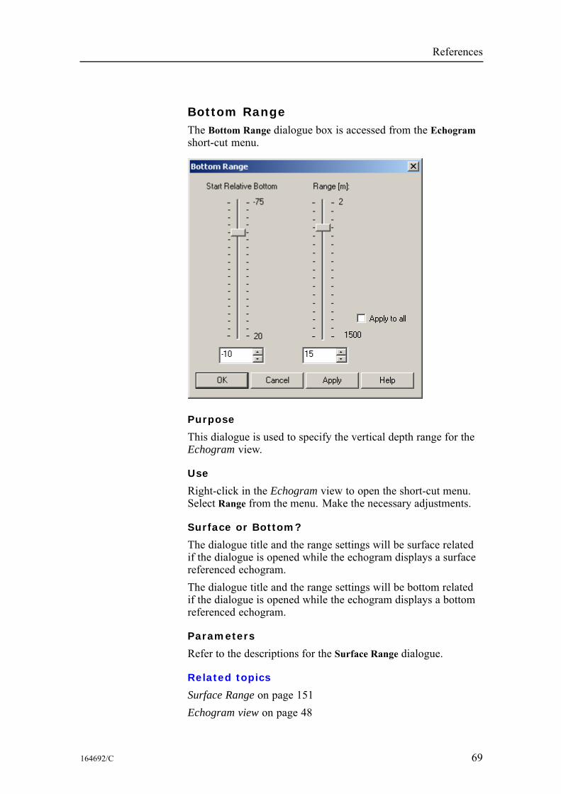
References
Bottom RangeThe Bottom Range dialogue box is accessed from the Echogramshort-cut menu.
Purpose
This dialogue is used to specify the vertical depth range for theEchogram view.
Use
Right-click in the Echogram view to open the short-cut menu.Select Range from the menu. Make the necessary adjustments.
Surface or Bottom?
The dialogue title and the range settings will be surface relatedif the dialogue is opened while the echogram displays a surfacereferenced echogram.The dialogue title and the range settings will be bottom relatedif the dialogue is opened while the echogram displays a bottomreferenced echogram.
Parameters
Refer to the descriptions for the Surface Range dialogue.
Related topics
Surface Range on page 151Echogram view on page 48
164692/C 69
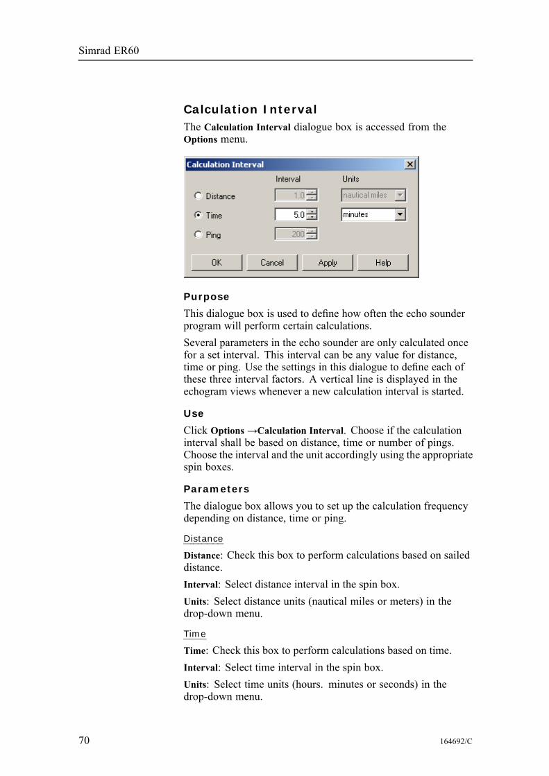
Simrad ER60
Calculation IntervalThe Calculation Interval dialogue box is accessed from theOptions menu.
Purpose
This dialogue box is used to define how often the echo sounderprogram will perform certain calculations.Several parameters in the echo sounder are only calculated oncefor a set interval. This interval can be any value for distance,time or ping. Use the settings in this dialogue to define each ofthese three interval factors. A vertical line is displayed in theechogram views whenever a new calculation interval is started.
Use
Click Options →Calculation Interval. Choose if the calculationinterval shall be based on distance, time or number of pings.Choose the interval and the unit accordingly using the appropriatespin boxes.
Parameters
The dialogue box allows you to set up the calculation frequencydepending on distance, time or ping.
Distance
Distance: Check this box to perform calculations based on saileddistance.Interval: Select distance interval in the spin box.Units: Select distance units (nautical miles or meters) in thedrop-down menu.
Time
Time: Check this box to perform calculations based on time.Interval: Select time interval in the spin box.Units: Select time units (hours. minutes or seconds) in thedrop-down menu.
70 164692/C

References
Ping
Ping: Check this box to perform calculations based on number ofpings.Interval: Select number of pings between each calculation inthe spin box.
Related topics
Numerical view on page 51
164692/C 71
Simrad ER60
CascadeThe Cascade function is accessed from theWindow menu.
Purpose
This command is used to display a new channel window. Thiscan either be a new frequency channel, or a new view of anexisting frequency channel.
Use
This function is identical to the common function available in theoperating system. The active windows are presented in cascade;that is partly on top of each other with the top bar shown.
Related topics
New Channel on page 122Close All on page 73Tile on page 153
72 164692/C
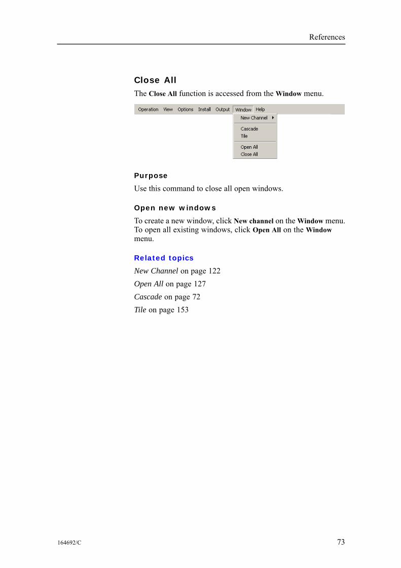
References
Close AllThe Close All function is accessed from theWindow menu.
Purpose
Use this command to close all open windows.
Open new windows
To create a new window, click New channel on theWindow menu.To open all existing windows, click Open All on the Windowmenu.
Related topics
New Channel on page 122Open All on page 127Cascade on page 72Tile on page 153
164692/C 73
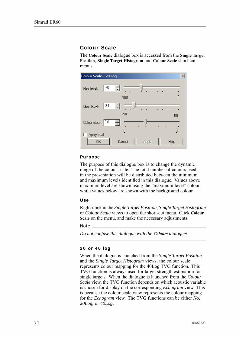
Simrad ER60
Colour ScaleThe Colour Scale dialogue box is accessed from the Single TargetPosition, Single Target Histogram and Colour Scale short-cutmenus.
Purpose
The purpose of this dialogue box is to change the dynamicrange of the colour scale. The total number of colours usedin the presentation will be distributed between the minimumand maximum levels identified in this dialogue. Values abovemaximum level are shown using the “maximum level” colour,while values below are shown with the background colour.
Use
Right-click in the Single Target Position, Single Target Histogramor Colour Scale views to open the short-cut menu. Click ColourScale on the menu, and make the necessary adjustments.Note
Do not confuse this dialogue with the Colours dialogue!
20 or 40 log
When the dialogue is launched from the Single Target Positionand the Single Target Histogram views, the colour scalerepresents colour mapping for the 40Log TVG function. ThisTVG function is always used for target strength estimation forsingle targets. When the dialogue is launched from the ColourScale view, the TVG function depends on which acoustic variableis chosen for display on the corresponding Echogram view. Thisis because the colour scale view represents the colour mappingfor the Echogram view. The TVG functions can be either No,20Log, or 40Log.
74 164692/C
References
Parameters
Min. level / Max. level: Use the spin boxes or sliders to setthe levels. Altering the maximum or minimum levels willautomatically adjust the colour step.Colour step: Use this setting to define the range in dB each colourwill cover. Altering the colour step will automatically adjust themaximum level.Apply to all: Check this box to make the chosen settings apply toall views.
Related topics
Colour scale view on page 50Single target histogram view on page 47Single target position view on page 46Colours on page 76
164692/C 75
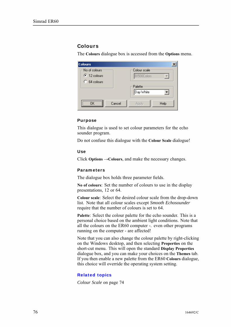
Simrad ER60
ColoursThe Colours dialogue box is accessed from the Options menu.
Purpose
This dialogue is used to set colour parameters for the echosounder program.Do not confuse this dialogue with the Colour Scale dialogue!
Use
Click Options→Colours, and make the necessary changes.
Parameters
The dialogue box holds three parameter fields.No of colours: Set the number of colours to use in the displaypresentations, 12 or 64.Colour scale: Select the desired colour scale from the drop-downlist. Note that all colour scales except Smooth Echosounderrequire that the number of colours is set to 64.Palette: Select the colour palette for the echo sounder. This is apersonal choice based on the ambient light conditions. Note thatall the colours on the ER60 computer -. even other programsrunning on the computer - are affected!Note that you can also change the colour palette by right-clickingon the Windows desktop, and then selecting Properties on theshort-cut menu. This will open the standard Display Propertiesdialogue box, and you can make your choices on the Themes tab.If you then enable a new palette from the ER60 Colours dialogue,this choice will override the operating system setting.
Related topics
Colour Scale on page 74
76 164692/C
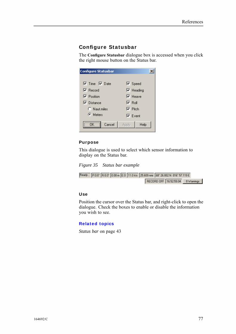
References
Configure StatusbarThe Configure Statusbar dialogue box is accessed when you clickthe right mouse button on the Status bar.
Purpose
This dialogue is used to select which sensor information todisplay on the Status bar.
Figure 35 Status bar example
Use
Position the cursor over the Status bar, and right-click to open thedialogue. Check the boxes to enable or disable the informationyou wish to see.
Related topics
Status bar on page 43
164692/C 77
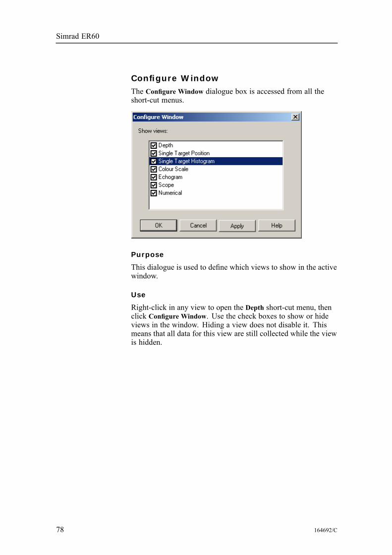
Simrad ER60
Configure WindowThe Configure Window dialogue box is accessed from all theshort-cut menus.
Purpose
This dialogue is used to define which views to show in the activewindow.
Use
Right-click in any view to open the Depth short-cut menu, thenclick Configure Window. Use the check boxes to show or hideviews in the window. Hiding a view does not disable it. Thismeans that all data for this view are still collected while the viewis hidden.
78 164692/C

References
ContentsThe Contents function is accessed from the Help menu.
Purpose
Use this option to open the first page of the context sensitiveon-line help system.
164692/C 79
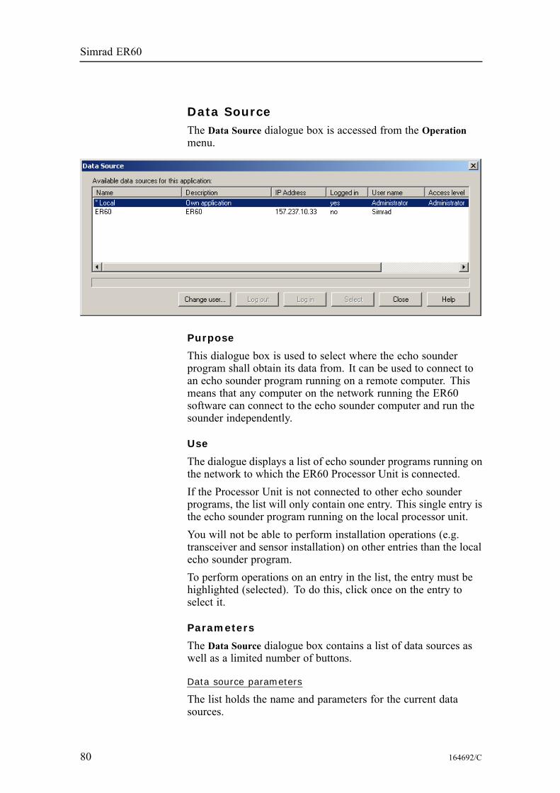
Simrad ER60
Data SourceThe Data Source dialogue box is accessed from the Operationmenu.
Purpose
This dialogue box is used to select where the echo sounderprogram shall obtain its data from. It can be used to connect toan echo sounder program running on a remote computer. Thismeans that any computer on the network running the ER60software can connect to the echo sounder computer and run thesounder independently.
Use
The dialogue displays a list of echo sounder programs running onthe network to which the ER60 Processor Unit is connected.If the Processor Unit is not connected to other echo sounderprograms, the list will only contain one entry. This single entry isthe echo sounder program running on the local processor unit.You will not be able to perform installation operations (e.g.transceiver and sensor installation) on other entries than the localecho sounder program.To perform operations on an entry in the list, the entry must behighlighted (selected). To do this, click once on the entry toselect it.
Parameters
The Data Source dialogue box contains a list of data sources aswell as a limited number of buttons.
Data source parameters
The list holds the name and parameters for the current datasources.
80 164692/C
References
Name: This column displays the installation name of the echosounder program entry. An asterisk (*) in front of an entry meansthat this entry is currently selected data source. Only one entrycan be selected at a time. The installation name is defined inthe Remoting dialogue.Description: This column displays a short description of thisprogram. The description is defined in the Remoting dialogue.IP address: This column displays the IP address of the computerrunning the echo sounder program.Logged in: This column displays if the you are logged in to thisecho sounder program entry.User name: This column displays the user name to be usedwhen logging in to the program. The user name must existon the remote application for the log in to succeed. For moreinformation on adding users refer to the Remoting dialogue.Access level: This column displays the access level for the username.
Buttons
Change user: Click this button to change the user name usedwhen logging in to the selected entry. Once pressed, the Usersand Passwords dialogue box opens.Log in: Click this button to log in to the selected entry.Log out: Click this button to log out from the selected entry.Select: Click this button to define the selected (highlighted) entryas the current data source.
Related topics
Remoting on page 139Log In on page 115Users and Passwords on page 163
164692/C 81
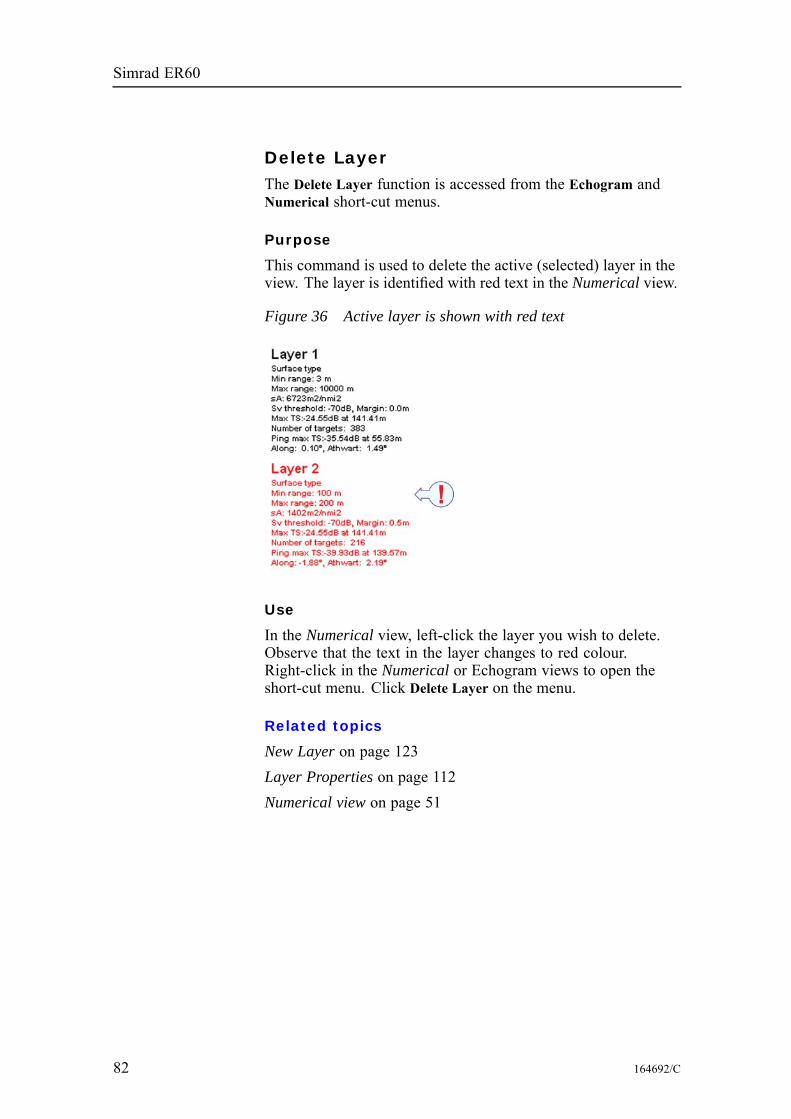
Simrad ER60
Delete LayerThe Delete Layer function is accessed from the Echogram andNumerical short-cut menus.
Purpose
This command is used to delete the active (selected) layer in theview. The layer is identified with red text in the Numerical view.
Figure 36 Active layer is shown with red text
Use
In the Numerical view, left-click the layer you wish to delete.Observe that the text in the layer changes to red colour.Right-click in the Numerical or Echogram views to open theshort-cut menu. Click Delete Layer on the menu.
Related topics
New Layer on page 123Layer Properties on page 112Numerical view on page 51
82 164692/C
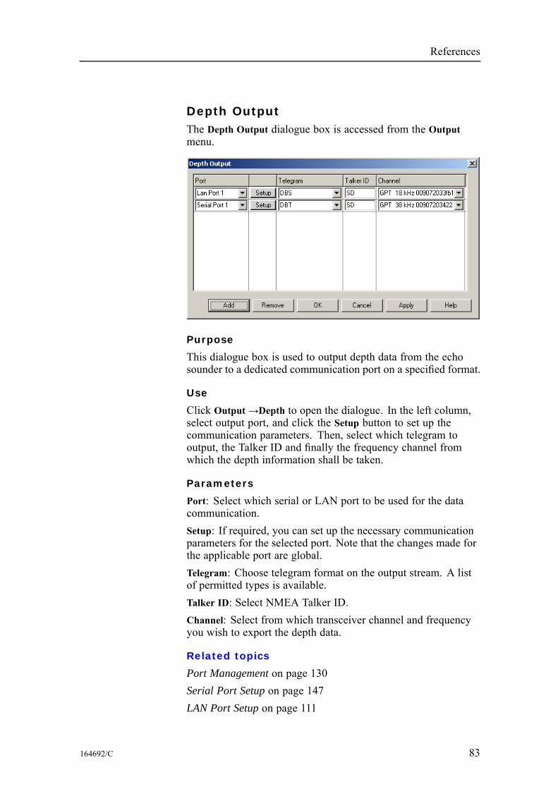
References
Depth OutputThe Depth Output dialogue box is accessed from the Outputmenu.
Purpose
This dialogue box is used to output depth data from the echosounder to a dedicated communication port on a specified format.
Use
Click Output→Depth to open the dialogue. In the left column,select output port, and click the Setup button to set up thecommunication parameters. Then, select which telegram tooutput, the Talker ID and finally the frequency channel fromwhich the depth information shall be taken.
Parameters
Port: Select which serial or LAN port to be used for the datacommunication.Setup: If required, you can set up the necessary communicationparameters for the selected port. Note that the changes made forthe applicable port are global.Telegram: Choose telegram format on the output stream. A listof permitted types is available.Talker ID: Select NMEA Talker ID.Channel: Select from which transceiver channel and frequencyyou wish to export the depth data.
Related topics
Port Management on page 130Serial Port Setup on page 147LAN Port Setup on page 111
164692/C 83

Simrad ER60
EchogramThe Echogram dialogue box is accessed from the Echogramshort-cut menu.
Purpose
This dialogue box is used to specify what should be displayed inthe Echogram view, and how sample data shall be converted topixel data. The following tabs are used:• Type• Lines• Pixels
Use
Right-click in the Echogram view to open the short-cut menu,and select Echogram. Make the necessary adjustments.
Related topics
Surface Range on page 151Bottom Range on page 69Echogram view on page 48Annotation on page 65
84 164692/C
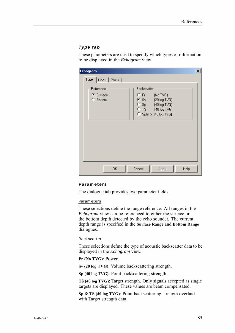
References
Type tab
These parameters are used to specify which types of informationto be displayed in the Echogram view.
Parameters
The dialogue tab provides two parameter fields.
Parameters
These selections define the range reference. All ranges in theEchogram view can be referenced to either the surface orthe bottom depth detected by the echo sounder. The currentdepth range is specified in the Surface Range and Bottom Rangedialogues.
Backscatter
These selections define the type of acoustic backscatter data to bedisplayed in the Echogram view.Pr (No TVG): Power.Sv (20 log TVG): Volume backscattering strength.Sp (40 log TVG): Point backscattering strength.TS (40 log TVG): Target strength. Only signals accepted as singletargets are displayed. These values are beam compensated.Sp & TS (40 log TVG): Point backscattering strength overlaidwith Target strength data.
164692/C 85
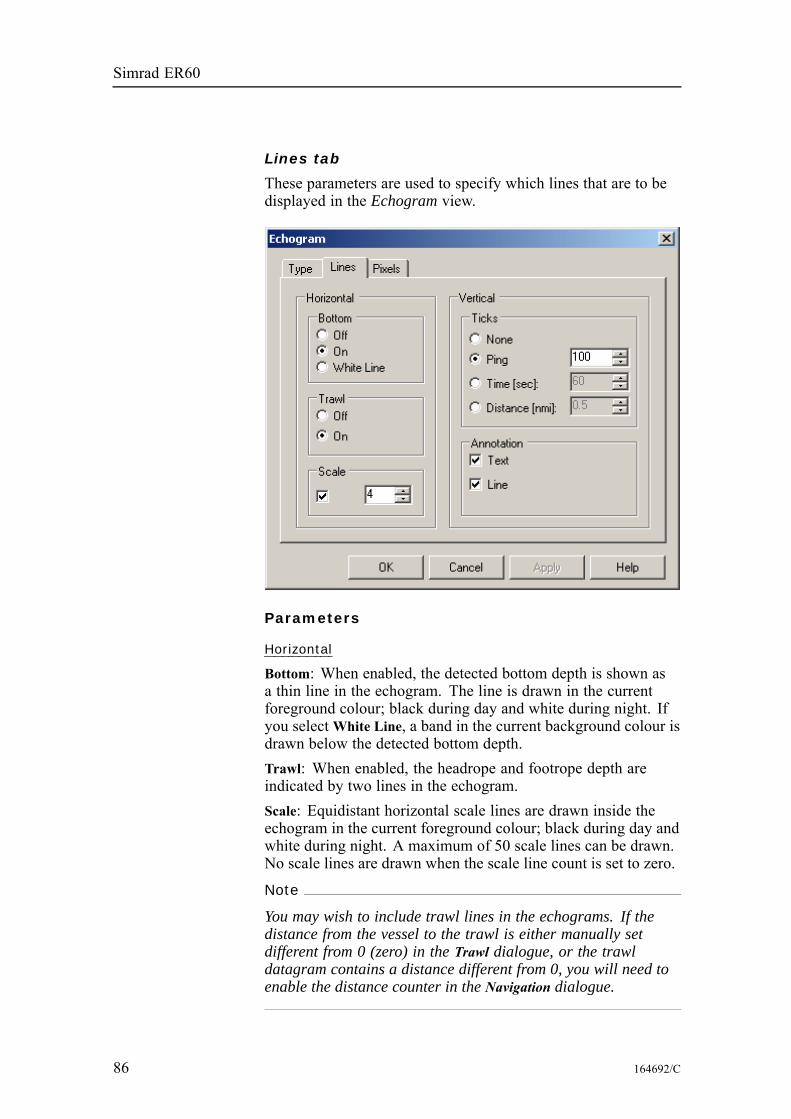
Simrad ER60
Lines tab
These parameters are used to specify which lines that are to bedisplayed in the Echogram view.
Parameters
Horizontal
Bottom: When enabled, the detected bottom depth is shown asa thin line in the echogram. The line is drawn in the currentforeground colour; black during day and white during night. Ifyou selectWhite Line, a band in the current background colour isdrawn below the detected bottom depth.Trawl: When enabled, the headrope and footrope depth areindicated by two lines in the echogram.Scale: Equidistant horizontal scale lines are drawn inside theechogram in the current foreground colour; black during day andwhite during night. A maximum of 50 scale lines can be drawn.No scale lines are drawn when the scale line count is set to zero.
Note
You may wish to include trawl lines in the echograms. If thedistance from the vessel to the trawl is either manually setdifferent from 0 (zero) in the Trawl dialogue, or the trawldatagram contains a distance different from 0, you will need toenable the distance counter in the Navigation dialogue.
86 164692/C
References
Vertical
Ticks: When enabled, this function places vertical markers on theechogram. If you select Ping, a short vertical line is drawn inthe upper part of the echogram once every specified number ofpings. Time places a short vertical line is drawn in the upper partof the echogram once every specified number of seconds, whileDistance inserts a short vertical line is drawn in the upper part ofthe echogram once every specified number of nautical miles.Annotation: Select Text or Line to allow annotations to bedisplayed in the Echogram view. If you click Line, the textannotation will be followed by a vertical line for improvedvisibility.
164692/C 87
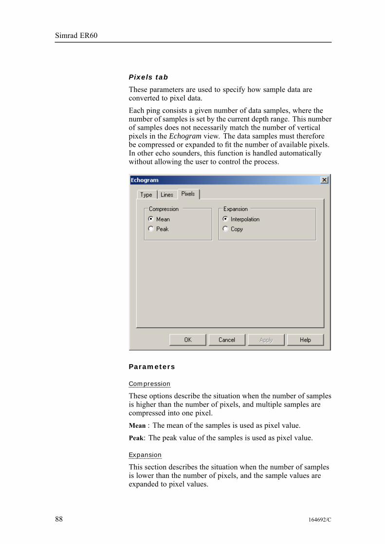
Simrad ER60
Pixels tab
These parameters are used to specify how sample data areconverted to pixel data.Each ping consists a given number of data samples, where thenumber of samples is set by the current depth range. This numberof samples does not necessarily match the number of verticalpixels in the Echogram view. The data samples must thereforebe compressed or expanded to fit the number of available pixels.In other echo sounders, this function is handled automaticallywithout allowing the user to control the process.
Parameters
Compression
These options describe the situation when the number of samplesis higher than the number of pixels, and multiple samples arecompressed into one pixel.Mean : The mean of the samples is used as pixel value.Peak: The peak value of the samples is used as pixel value.
Expansion
This section describes the situation when the number of samplesis lower than the number of pixels, and the sample values areexpanded to pixel values.
88 164692/C

References
Interpolation: Pixel values are interpolated between two samplevalues.Copy: A sample value is copied into multiple pixel values.
164692/C 89
Simrad ER60
EK500 DatagramThe EK500 Datagram dialogue box is accessed from the FileOutput and Ethernet Output dialogues.
Purpose
This dialogue is used to specify which EK500 datagrams tooutput. Note that changes made in this dialogue will have effectson both Ethernet and file output of EK500 data.• Datagram• Range• Echogram
Use
Access the dialogue from the File Output or Ethernet Outputdialogues. Make the necessary adjustments.
Related topics
Single Target Detection on page 148Surface Range on page 151Bottom Range on page 69
90 164692/C
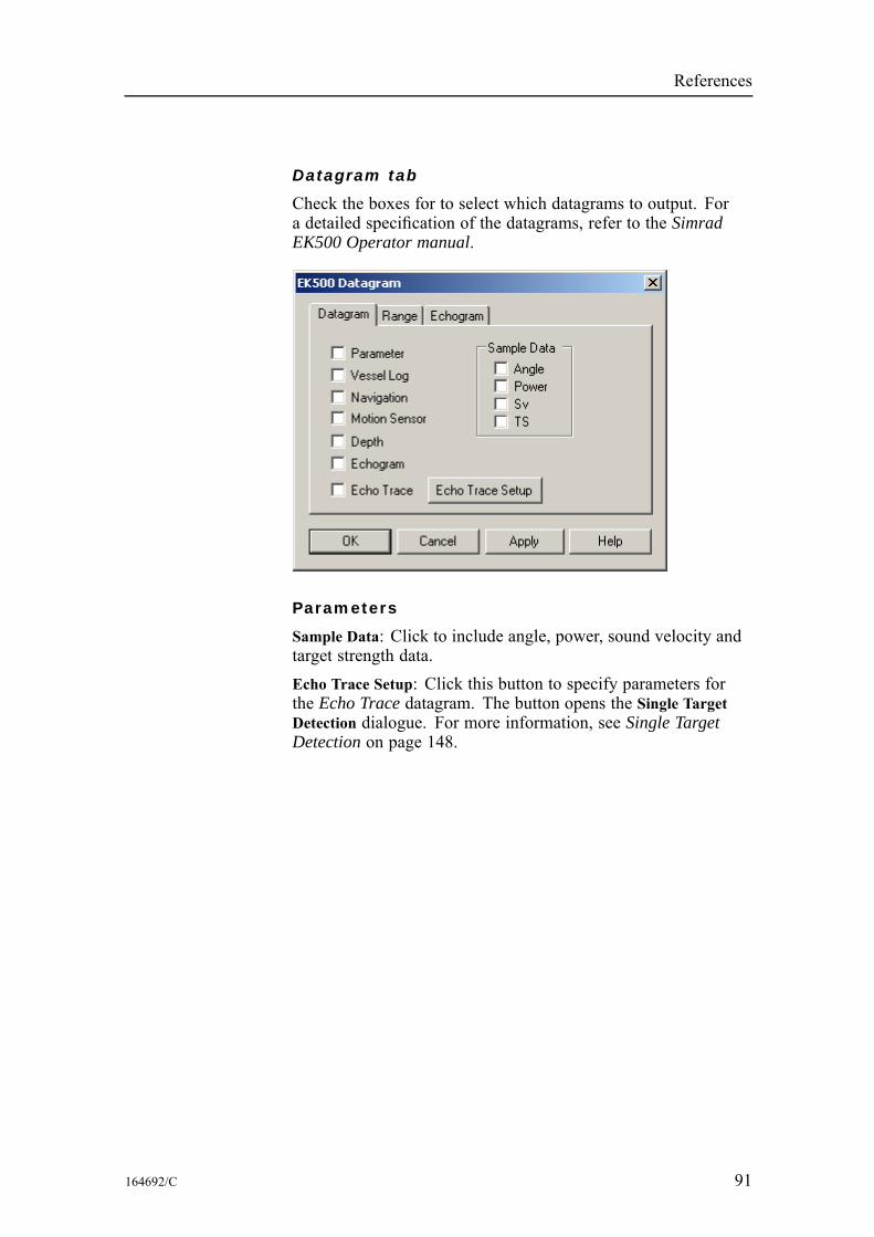
References
Datagram tab
Check the boxes for to select which datagrams to output. Fora detailed specification of the datagrams, refer to the SimradEK500 Operator manual.
Parameters
Sample Data: Click to include angle, power, sound velocity andtarget strength data.Echo Trace Setup: Click this button to specify parameters forthe Echo Trace datagram. The button opens the Single TargetDetection dialogue. For more information, see Single TargetDetection on page 148.
164692/C 91
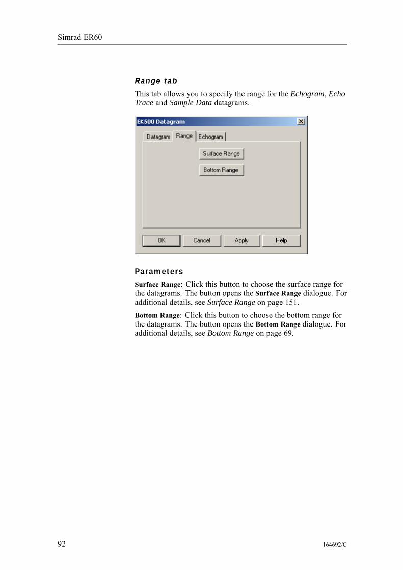
Simrad ER60
Range tab
This tab allows you to specify the range for the Echogram, EchoTrace and Sample Data datagrams.
Parameters
Surface Range: Click this button to choose the surface range forthe datagrams. The button opens the Surface Range dialogue. Foradditional details, see Surface Range on page 151.Bottom Range: Click this button to choose the bottom range forthe datagrams. The button opens the Bottom Range dialogue. Foradditional details, see Bottom Range on page 69.
92 164692/C
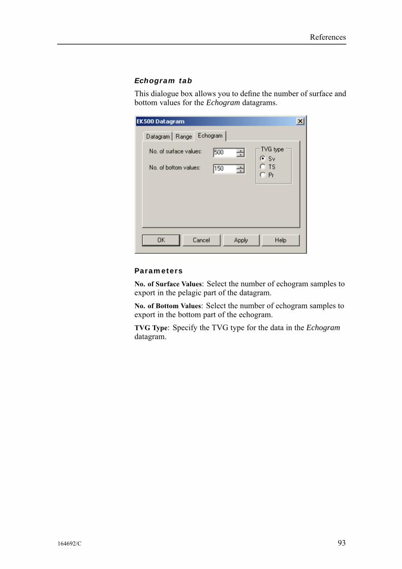
References
Echogram tab
This dialogue box allows you to define the number of surface andbottom values for the Echogram datagrams.
Parameters
No. of Surface Values: Select the number of echogram samples toexport in the pelagic part of the datagram.No. of Bottom Values: Select the number of echogram samples toexport in the bottom part of the echogram.TVG Type: Specify the TVG type for the data in the Echogramdatagram.
164692/C 93
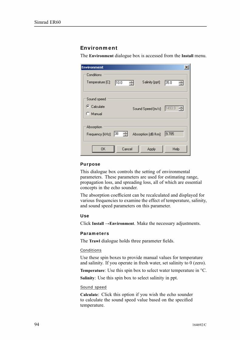
Simrad ER60
EnvironmentThe Environment dialogue box is accessed from the Install menu.
Purpose
This dialogue box controls the setting of environmentalparameters. These parameters are used for estimating range,propagation loss, and spreading loss, all of which are essentialconcepts in the echo sounder.The absorption coefficient can be recalculated and displayed forvarious frequencies to examine the effect of temperature, salinity,and sound speed parameters on this parameter.
Use
Click Install→Environment. Make the necessary adjustments.
Parameters
The Trawl dialogue holds three parameter fields.
Conditions
Use these spin boxes to provide manual values for temperatureand salinity. If you operate in fresh water, set salinity to 0 (zero).Temperature: Use this spin box to select water temperature in °C.Salinity: Use this spin box to select salinity in ppt.
Sound speed
Calculate: Click this option if you wish the echo sounderto calculate the sound speed value based on the specifiedtemperature.
94 164692/C

References
Manual: Click this option if you wish to enter the sound speedmanually. Use the spin box.
Absorption
Select the frequency in the top spin box, and read thecorresponding absorption value. This input has no effect on theecho sounder, it is simply a calculator!
164692/C 95
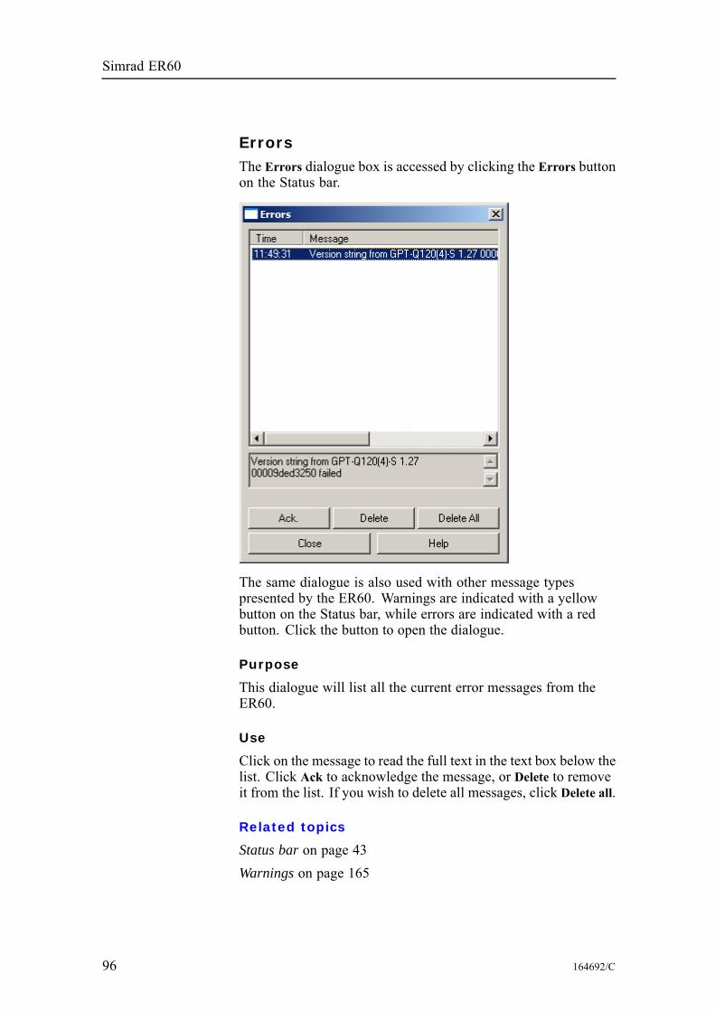
Simrad ER60
ErrorsThe Errors dialogue box is accessed by clicking the Errors buttonon the Status bar.
The same dialogue is also used with other message typespresented by the ER60. Warnings are indicated with a yellowbutton on the Status bar, while errors are indicated with a redbutton. Click the button to open the dialogue.
Purpose
This dialogue will list all the current error messages from theER60.
Use
Click on the message to read the full text in the text box below thelist. Click Ack to acknowledge the message, or Delete to removeit from the list. If you wish to delete all messages, click Delete all.
Related topics
Status bar on page 43Warnings on page 165
96 164692/C
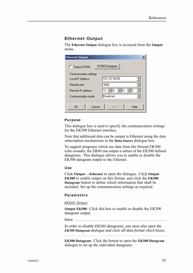
References
Ethernet OutputThe Ethernet Output dialogue box is accessed from the Outputmenu.
Purpose
This dialogue box is used to specify the communication settingsfor the EK500 Ethernet interface.Note that additional data can be output to Ethernet using the datasubscription mechanisms in the Data Source dialogue box.To support programs which use data from the Simrad EK500echo sounder, the ER60 can output a subset of the EK500 defineddatagrams. This dialogue allows you to enable or disable theEK500 datagram output to the Ethernet.
Use
Click Output →Ethernet to open the dialogue. Click OutputEK500 to enable output on this format, and click the EK500Datagram button to define which information that shall beincluded. Set up the communication settings as required.
Parameters
EK500 Output
Output EK500: Click this box to enable or disable the EK500datagram output.
Note
In order to disable EK500 datagrams, you must also open theEK500 Datagram dialogue and clear all data format check boxes.
EK500 Datagram: Click the button to open the EK500 Datagramdialogue to set up the individual datagrams.
164692/C 97
Simrad ER60
Communication parameters
Remote port: Use the spin box to define the UDP port number towhich the data shall be transmitted. Note that parameter request(PR) is only accepted on port 2000.Remote IP address: Use the spin boxes to define the IP Addressof the remote computer.Local IP Address: If you have more than one network cards inyour ER60 Processing Unit, use this box to select which networkcard to use for output data.Communication mode: Choose Broadcast or Point-to-Point.
Related topics
Data Source on page 80EK500 Datagram on page 90
98 164692/C
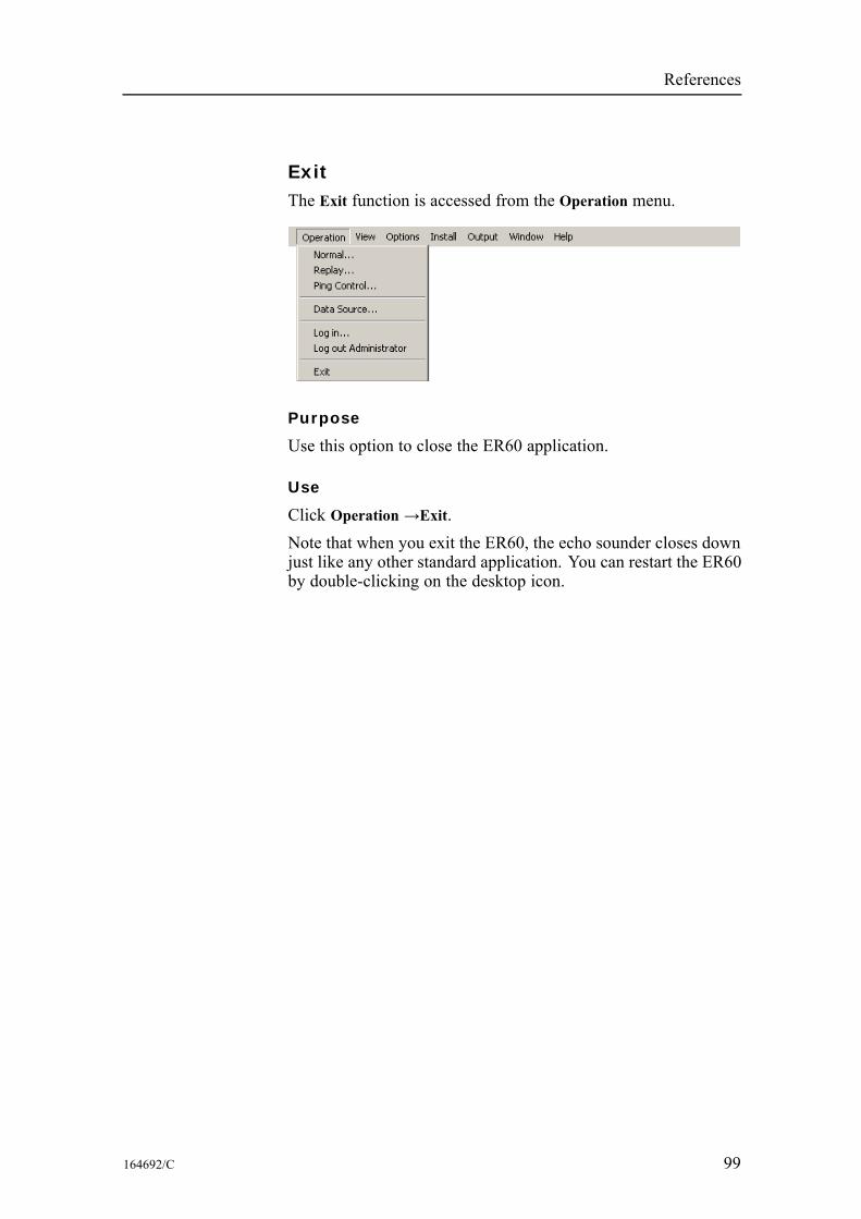
References
ExitThe Exit function is accessed from the Operation menu.
Purpose
Use this option to close the ER60 application.
Use
Click Operation →Exit.Note that when you exit the ER60, the echo sounder closes downjust like any other standard application. You can restart the ER60by double-clicking on the desktop icon.
164692/C 99
Simrad ER60
File OutputThe File Output dialogue box is accessed from the Output menu.
Purpose
This dialogue box is used to specify which output you wish tosave to a data file, and in which disk directory the data file(s)shall be placed. The dialogue provides three tabs:• Directory• Raw Data• Processed Data
Use
Click Output→File Output. Click one of the three tabs, and makethe necessary adjustments.
Related topics
Replay on page 144EK500 Datagram on page 90HAC Datagram on page 106
100 164692/C
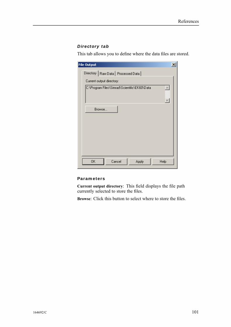
References
Directory tab
This tab allows you to define where the data files are stored.
Parameters
Current output directory: This field displays the file pathcurrently selected to store the files.Browse: Click this button to select where to store the files.
164692/C 101
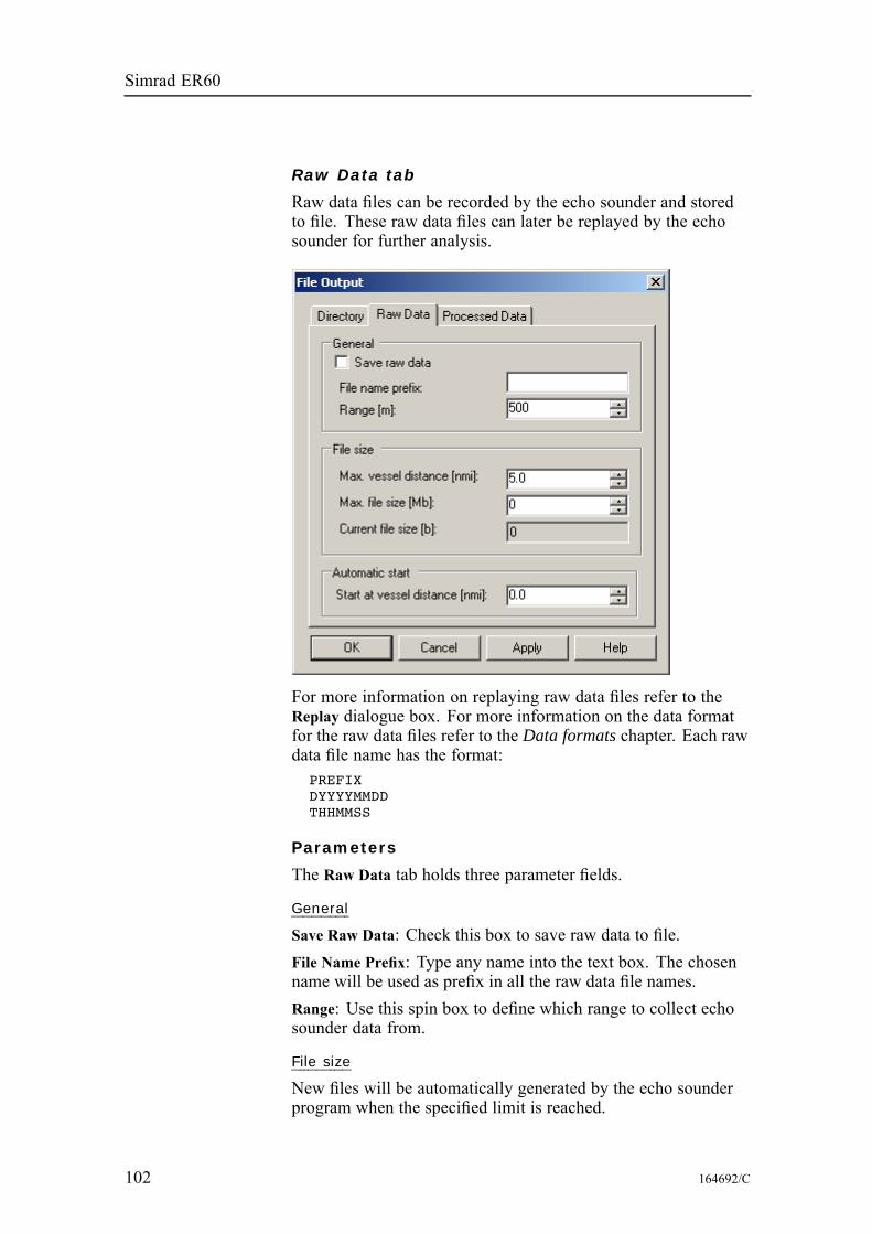
Simrad ER60
Raw Data tab
Raw data files can be recorded by the echo sounder and storedto file. These raw data files can later be replayed by the echosounder for further analysis.
For more information on replaying raw data files refer to theReplay dialogue box. For more information on the data formatfor the raw data files refer to the Data formats chapter. Each rawdata file name has the format:
PREFIXDYYYYMMDDTHHMMSS
Parameters
The Raw Data tab holds three parameter fields.
General
Save Raw Data: Check this box to save raw data to file.File Name Prefix: Type any name into the text box. The chosenname will be used as prefix in all the raw data file names.Range: Use this spin box to define which range to collect echosounder data from.
File size
New files will be automatically generated by the echo sounderprogram when the specified limit is reached.
102 164692/C
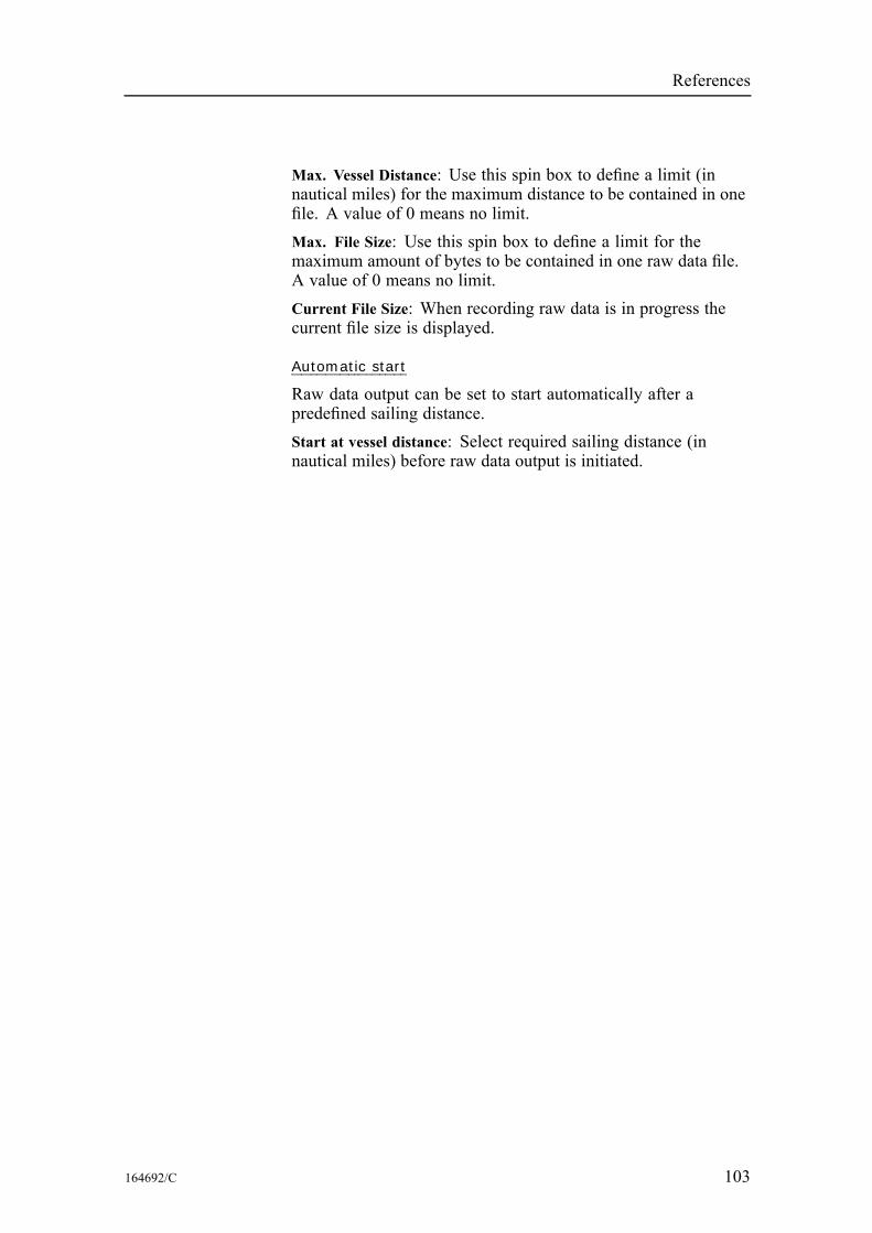
References
Max. Vessel Distance: Use this spin box to define a limit (innautical miles) for the maximum distance to be contained in onefile. A value of 0 means no limit.Max. File Size: Use this spin box to define a limit for themaximum amount of bytes to be contained in one raw data file.A value of 0 means no limit.Current File Size: When recording raw data is in progress thecurrent file size is displayed.
Automatic start
Raw data output can be set to start automatically after apredefined sailing distance.Start at vessel distance: Select required sailing distance (innautical miles) before raw data output is initiated.
164692/C 103
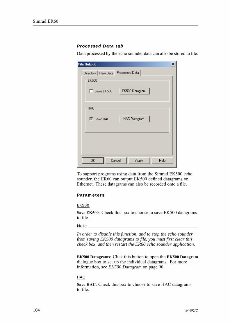
Simrad ER60
Processed Data tab
Data processed by the echo sounder data can also be stored to file.
To support programs using data from the Simrad EK500 echosounder, the ER60 can output EK500 defined datagrams onEthernet. These datagrams can also be recorded onto a file.
Parameters
EK500
Save EK500: Check this box to choose to save EK500 datagramsto file.
Note
In order to disable this function, and to stop the echo sounderfrom saving EK500 datagrams to file, you must first clear thischeck box, and then restart the ER60 echo sounder application.
EK500 Datagrams: Click this button to open the EK500 Datagramdialogue box to set up the individual datagrams. For moreinformation, see EK500 Datagram on page 90.
HAC
Save HAC: Check this box to choose to save HAC datagramsto file.
104 164692/C

References
HAC Datagram: Click this button to open the HAC Datagramdialogue box to set up the individual datagrams. For moreinformation, see HAC Datagram on page 106.
164692/C 105
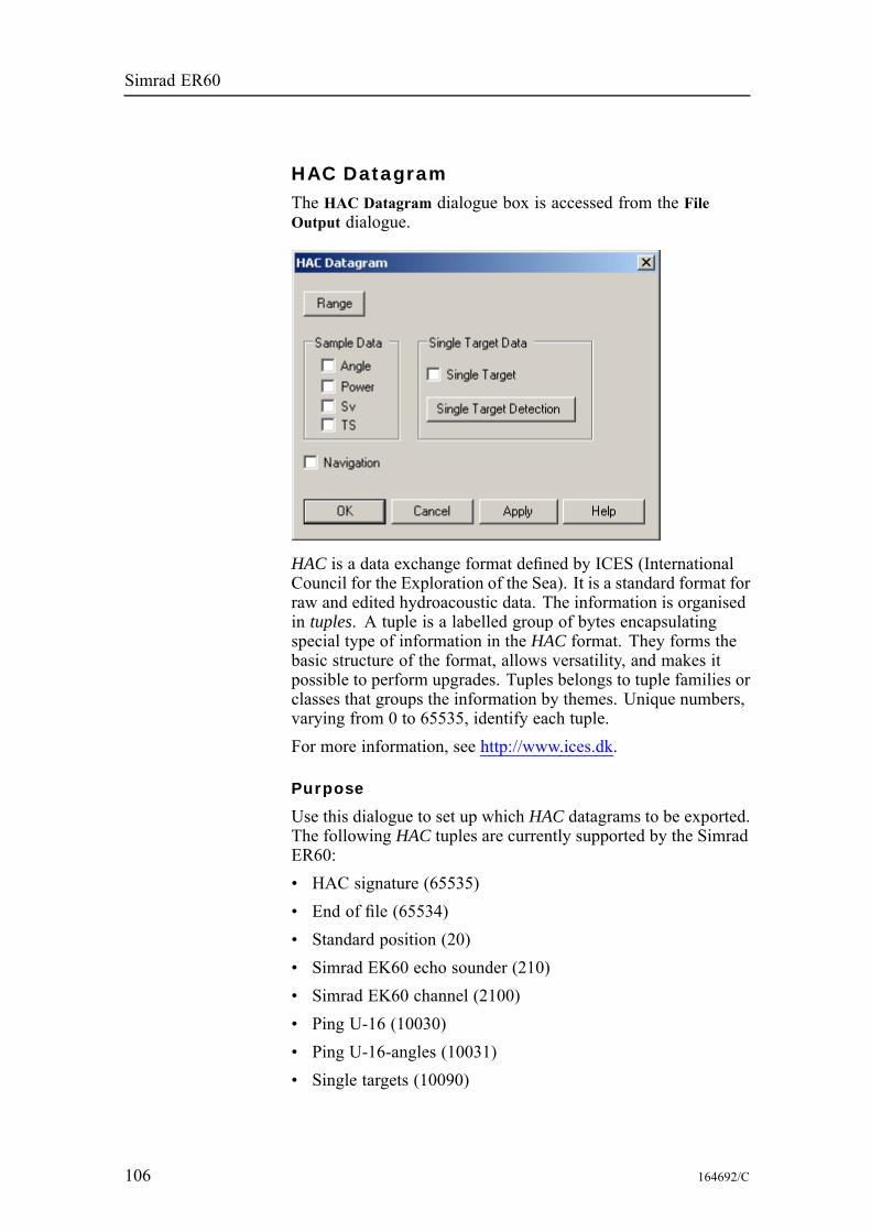
Simrad ER60
HAC DatagramThe HAC Datagram dialogue box is accessed from the FileOutput dialogue.
HAC is a data exchange format defined by ICES (InternationalCouncil for the Exploration of the Sea). It is a standard format forraw and edited hydroacoustic data. The information is organisedin tuples. A tuple is a labelled group of bytes encapsulatingspecial type of information in the HAC format. They forms thebasic structure of the format, allows versatility, and makes itpossible to perform upgrades. Tuples belongs to tuple families orclasses that groups the information by themes. Unique numbers,varying from 0 to 65535, identify each tuple.For more information, see http://www.ices.dk.
Purpose
Use this dialogue to set up which HAC datagrams to be exported.The following HAC tuples are currently supported by the SimradER60:• HAC signature (65535)• End of file (65534)• Standard position (20)• Simrad EK60 echo sounder (210)• Simrad EK60 channel (2100)• Ping U-16 (10030)• Ping U-16-angles (10031)• Single targets (10090)
106 164692/C
References
Use
Access the dialogue from the File Output dialogue. Make thenecessary adjustments.
Parameters
Range: Click to open the Surface Range dialogue. The rangespecified is the valid range for all ping and single targets HACdata.Navigation: Click to enable export of position data.
Sample data
Click to select which sample data types to export: angle, power,sound velocity or target strength.
Single target data
Single Target: Click to enable export of single target data.Single Target Detection: Click this button to define the singletarget detection properties. The Single Target Detection dialogueopens.
Related topics
File Output on page 100Single Target Detection on page 148Surface Range on page 151
164692/C 107
Simrad ER60
Hide ViewThe Hide View function is accessed from all the short-cut menus.
Purpose
This function hides the view from which the command waschosen.
Use
Right-click in any view to open the short-cut menu, then clickHide View.The view can be re-established by selecting Configure Windowfrom the short-cut menu in another view in the same window, andcheck the box for the view which was initially hidden.
Related topics
Configure Window on page 78
108 164692/C
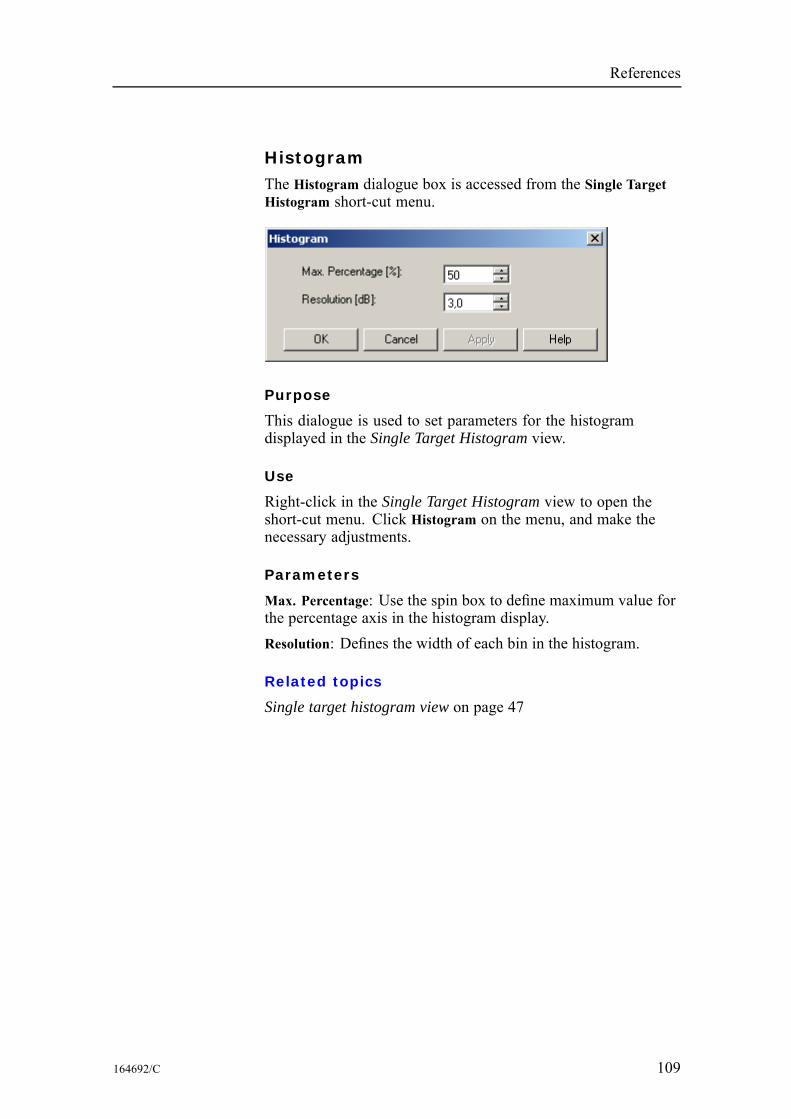
References
HistogramThe Histogram dialogue box is accessed from the Single TargetHistogram short-cut menu.
Purpose
This dialogue is used to set parameters for the histogramdisplayed in the Single Target Histogram view.
Use
Right-click in the Single Target Histogram view to open theshort-cut menu. Click Histogram on the menu, and make thenecessary adjustments.
Parameters
Max. Percentage: Use the spin box to define maximum value forthe percentage axis in the histogram display.Resolution: Defines the width of each bin in the histogram.
Related topics
Single target histogram view on page 47
164692/C 109
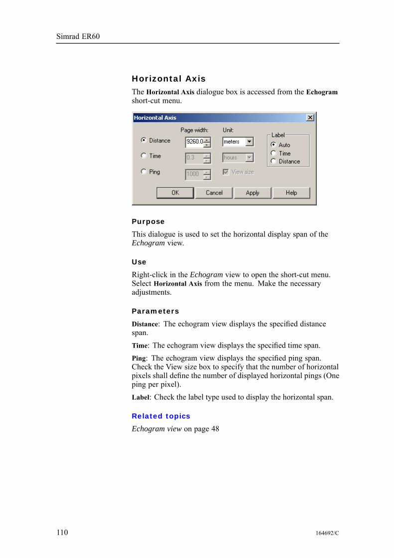
Simrad ER60
Horizontal AxisThe Horizontal Axis dialogue box is accessed from the Echogramshort-cut menu.
Purpose
This dialogue is used to set the horizontal display span of theEchogram view.
Use
Right-click in the Echogram view to open the short-cut menu.Select Horizontal Axis from the menu. Make the necessaryadjustments.
Parameters
Distance: The echogram view displays the specified distancespan.Time: The echogram view displays the specified time span.Ping: The echogram view displays the specified ping span.Check the View size box to specify that the number of horizontalpixels shall define the number of displayed horizontal pings (Oneping per pixel).Label: Check the label type used to display the horizontal span.
Related topics
Echogram view on page 48
110 164692/C
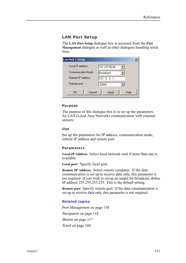
References
LAN Port SetupThe LAN Port Setup dialogue box is accessed from the PortManagement dialogue as well as other dialogues handling seriallines.
Purpose
The purpose of this dialogue box is to set up the parametersfor LAN (Local Area Network) communication with externalsensors.
Use
Set up the parameters for IP address, communication mode,remote IP address and remote port.
Parameters
Local IP Address: Select local network card if more than one isavailable.Local port: Specify local port.Remote IP Address: Select remote computer. If the datacommunication is set up to receive data only, this parameter isnot required. If you wish to set up an output for broadcast, defineIP address 255.255.255.255. This is the default setting.Remote port: Specify remote port. If the data communication isset up to receive data only, this parameter is not required.
Related topics
Port Management on page 130Navigation on page 118Motion on page 117Trawl on page 160
164692/C 111
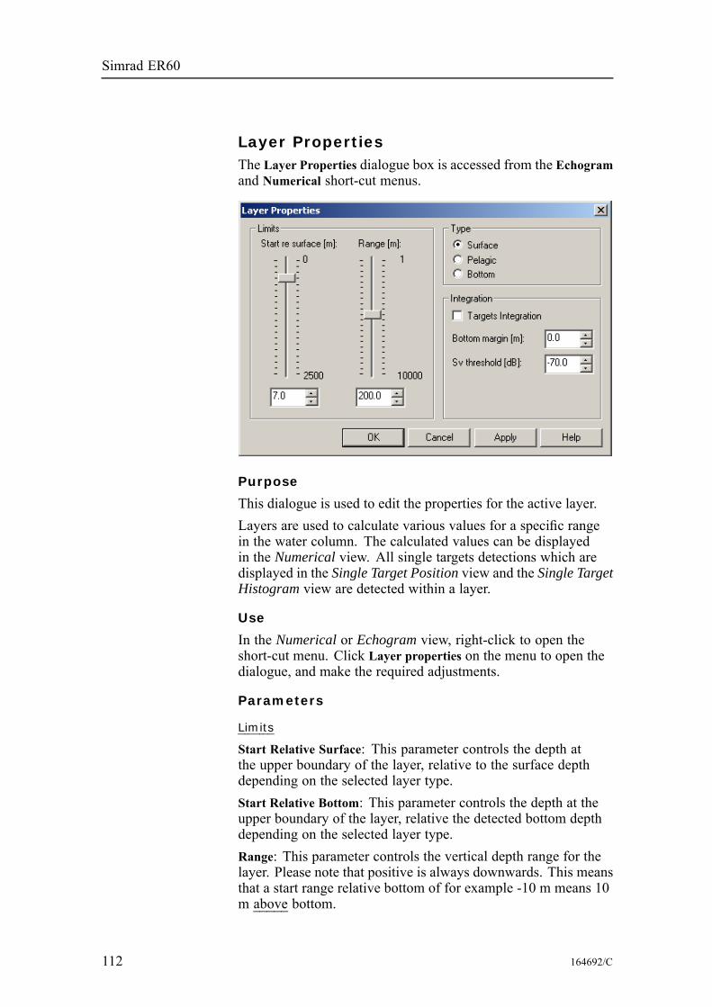
Simrad ER60
Layer PropertiesThe Layer Properties dialogue box is accessed from the Echogramand Numerical short-cut menus.
Purpose
This dialogue is used to edit the properties for the active layer.Layers are used to calculate various values for a specific rangein the water column. The calculated values can be displayedin the Numerical view. All single targets detections which aredisplayed in the Single Target Position view and the Single TargetHistogram view are detected within a layer.
Use
In the Numerical or Echogram view, right-click to open theshort-cut menu. Click Layer properties on the menu to open thedialogue, and make the required adjustments.
Parameters
Limits
Start Relative Surface: This parameter controls the depth atthe upper boundary of the layer, relative to the surface depthdepending on the selected layer type.Start Relative Bottom: This parameter controls the depth at theupper boundary of the layer, relative the detected bottom depthdepending on the selected layer type.Range: This parameter controls the vertical depth range for thelayer. Please note that positive is always downwards. This meansthat a start range relative bottom of for example -10 m means 10m above bottom.
112 164692/C
References
Type
Surface: The range settings for the layer are referenced to thesurface. The layer is downwards limited by the detected bottomdepth if this value is shallower than the specified lower rangelimit for the layer. Pings without bottom detections are ignoredin the calculations.Pelagic: The range settings for the layer are referenced to thesurface. The layer is not downwards limited by the detectedbottom depth.Bottom: The range settings for the layer are referenced to thebottom. The layer is downwards limited by the detected bottomdepth.
Integration
Targets Integration: Check this box to calculate integration valuesbased on single target detections. Compared with the normalintegration (sA) this value can be used to get an idea of howmuch of the biomass has been detected as single targets.Margin: This is the margin to the surface and the bottom usedwhen calculating integration values for Surface and Bottom types.Sv threshold: This is the lower threshold used when calculatingintegration values for the layer.
Related topics
New Layer on page 123Delete Layer on page 82Echogram view on page 48Numerical view on page 51
164692/C 113
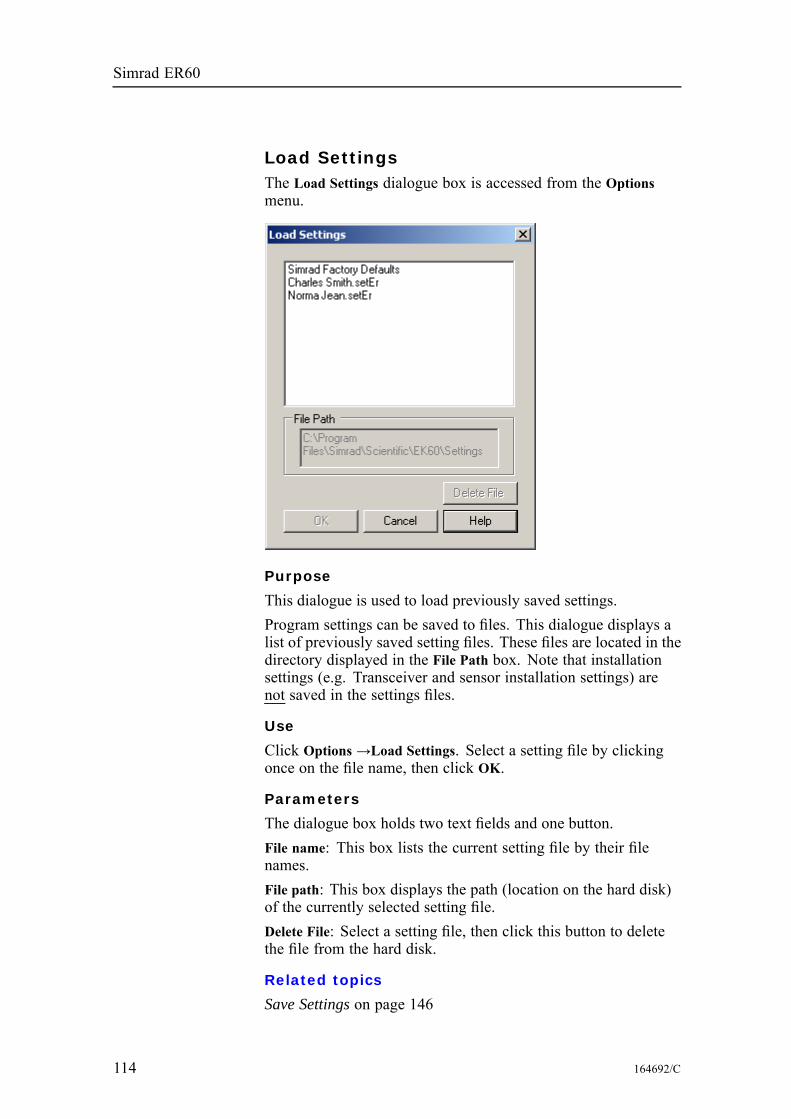
Simrad ER60
Load SettingsThe Load Settings dialogue box is accessed from the Optionsmenu.
Purpose
This dialogue is used to load previously saved settings.Program settings can be saved to files. This dialogue displays alist of previously saved setting files. These files are located in thedirectory displayed in the File Path box. Note that installationsettings (e.g. Transceiver and sensor installation settings) arenot saved in the settings files.
Use
Click Options →Load Settings. Select a setting file by clickingonce on the file name, then click OK.
Parameters
The dialogue box holds two text fields and one button.File name: This box lists the current setting file by their filenames.File path: This box displays the path (location on the hard disk)of the currently selected setting file.Delete File: Select a setting file, then click this button to deletethe file from the hard disk.
Related topics
Save Settings on page 146
114 164692/C
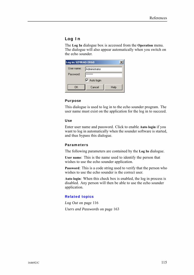
References
Log InThe Log In dialogue box is accessed from the Operation menu.The dialogue will also appear automatically when you switch onthe echo sounder.
Purpose
This dialogue is used to log in to the echo sounder program. Theuser name must exist on the application for the log in to succeed.
Use
Enter user name and password. Click to enable Auto login if youwant to log in automatically when the sounder software is started,and thus bypass this dialogue.
Parameters
The following parameters are contained by the Log In dialogue.User name: This is the name used to identify the person thatwishes to use the echo sounder application.Password: This is a code string used to verify that the person whowishes to use the echo sounder is the correct user.Auto login: When this check box is enabled, the log in process isdisabled. Any person will then be able to use the echo sounderapplication.
Related topics
Log Out on page 116Users and Passwords on page 163
164692/C 115
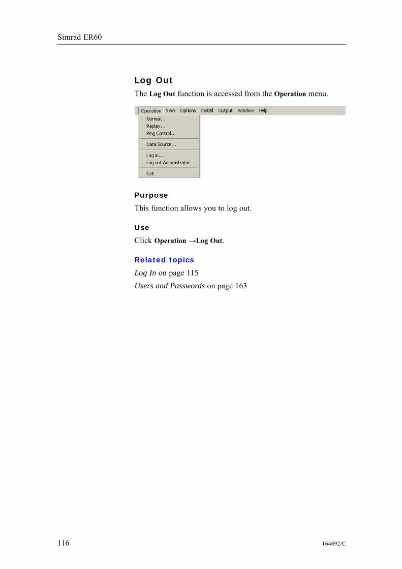
Simrad ER60
Log OutThe Log Out function is accessed from the Operation menu.
Purpose
This function allows you to log out.
Use
Click Operation →Log Out.
Related topics
Log In on page 115Users and Passwords on page 163
116 164692/C
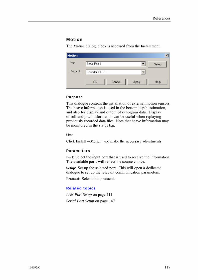
References
MotionThe Motion dialogue box is accessed from the Install menu.
Purpose
This dialogue controls the installation of external motion sensors.The heave information is used in the bottom depth estimation,and also for display and output of echogram data. Displayof roll and pitch information can be useful when replayingpreviously recorded data files. Note that heave information maybe monitored in the status bar.
Use
Click Install→Motion, and make the necessary adjustments.
Parameters
Port: Select the input port that is used to receive the information.The available ports will reflect the source choice.Setup: Set up the selected port. This will open a dedicateddialogue to set up the relevant communication parameters.Protocol: Select data protocol.
Related topics
LAN Port Setup on page 111Serial Port Setup on page 147
164692/C 117

Simrad ER60
NavigationThe Navigation dialogue box is accessed from the Install menu.
Purpose
This dialogue box controls the installation of position, speed,and travelled distance information from external sensors. Thedialogue provides three tabs:• Distance• Position• Speed
Use
Click Install→Navigation. Click one of the three tabs, and makethe necessary adjustments.
Related topics
LAN Port Setup on page 111Serial Port Setup on page 147
118 164692/C
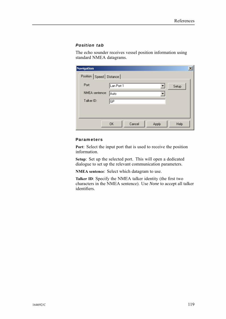
References
Position tab
The echo sounder receives vessel position information usingstandard NMEA datagrams.
Parameters
Port: Select the input port that is used to receive the positioninformation.Setup: Set up the selected port. This will open a dedicateddialogue to set up the relevant communication parameters.NMEA sentence: Select which datagram to use.Talker ID: Specify the NMEA talker identity (the first twocharacters in the NMEA sentence). Use None to accept all talkeridentifiers.
164692/C 119
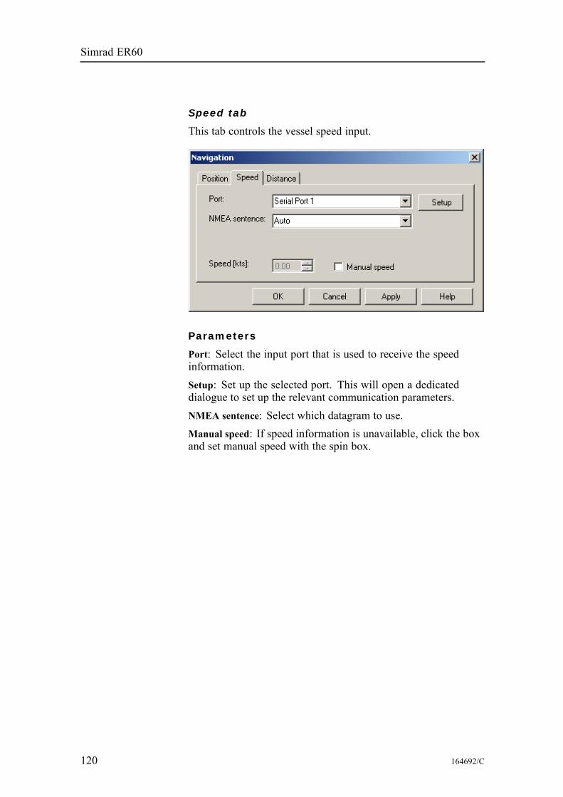
Simrad ER60
Speed tab
This tab controls the vessel speed input.
Parameters
Port: Select the input port that is used to receive the speedinformation.Setup: Set up the selected port. This will open a dedicateddialogue to set up the relevant communication parameters.NMEA sentence: Select which datagram to use.Manual speed: If speed information is unavailable, click the boxand set manual speed with the spin box.
120 164692/C
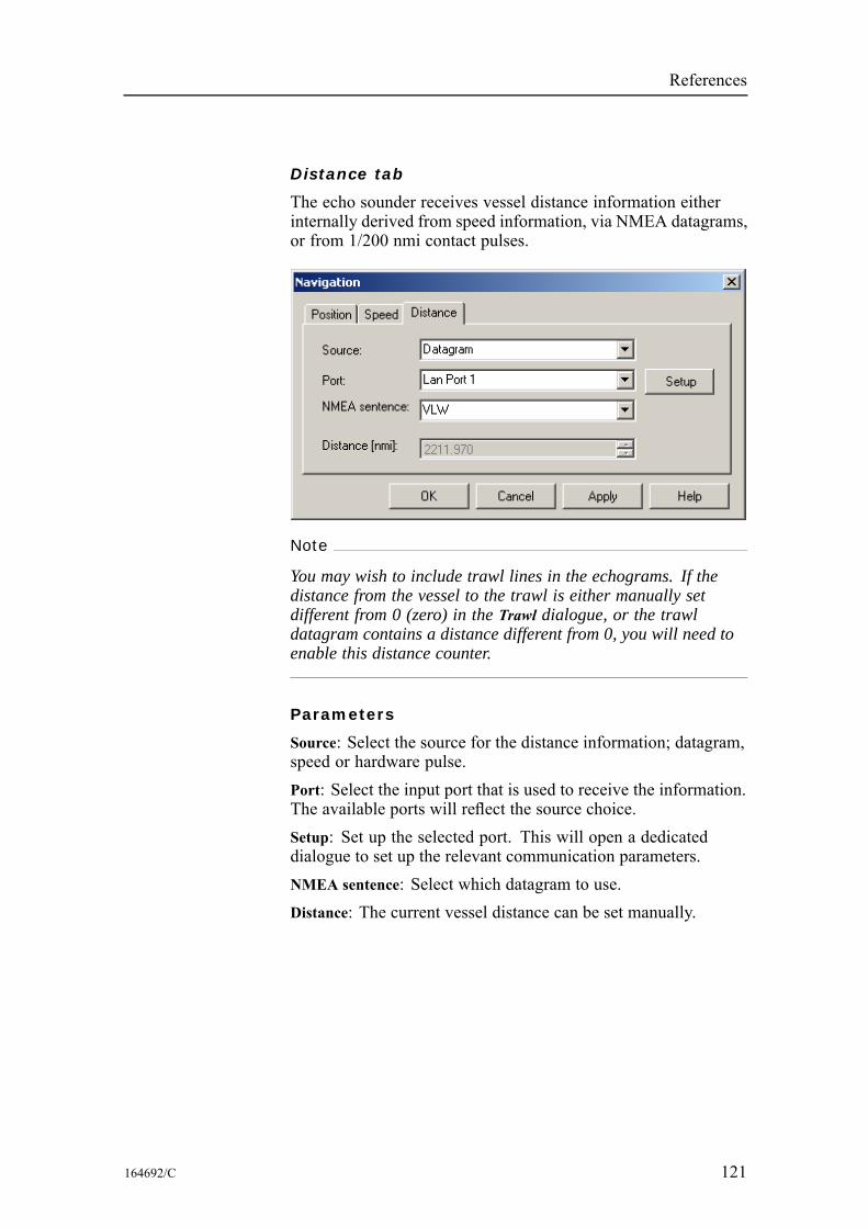
References
Distance tab
The echo sounder receives vessel distance information eitherinternally derived from speed information, via NMEA datagrams,or from 1/200 nmi contact pulses.
Note
You may wish to include trawl lines in the echograms. If thedistance from the vessel to the trawl is either manually setdifferent from 0 (zero) in the Trawl dialogue, or the trawldatagram contains a distance different from 0, you will need toenable this distance counter.
Parameters
Source: Select the source for the distance information; datagram,speed or hardware pulse.Port: Select the input port that is used to receive the information.The available ports will reflect the source choice.Setup: Set up the selected port. This will open a dedicateddialogue to set up the relevant communication parameters.NMEA sentence: Select which datagram to use.Distance: The current vessel distance can be set manually.
164692/C 121
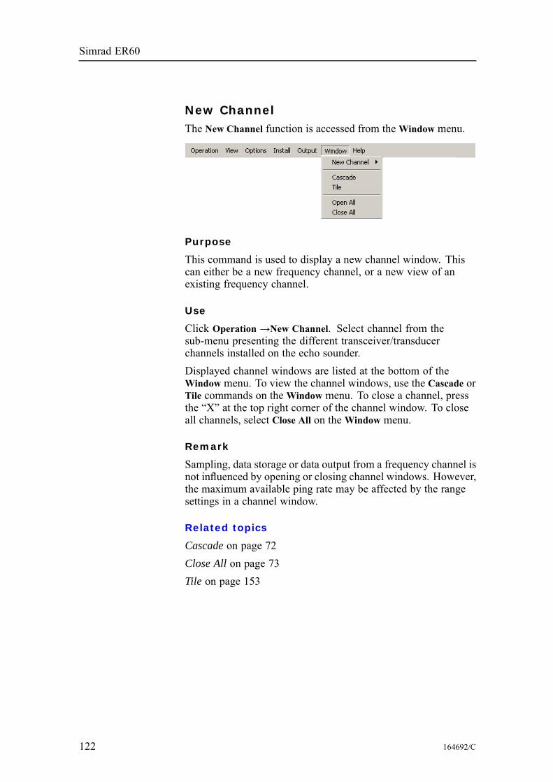
Simrad ER60
New ChannelThe New Channel function is accessed from theWindow menu.
Purpose
This command is used to display a new channel window. Thiscan either be a new frequency channel, or a new view of anexisting frequency channel.
Use
Click Operation →New Channel. Select channel from thesub-menu presenting the different transceiver/transducerchannels installed on the echo sounder.Displayed channel windows are listed at the bottom of theWindow menu. To view the channel windows, use the Cascade orTile commands on theWindow menu. To close a channel, pressthe “X” at the top right corner of the channel window. To closeall channels, select Close All on theWindow menu.
Remark
Sampling, data storage or data output from a frequency channel isnot influenced by opening or closing channel windows. However,the maximum available ping rate may be affected by the rangesettings in a channel window.
Related topics
Cascade on page 72Close All on page 73Tile on page 153
122 164692/C
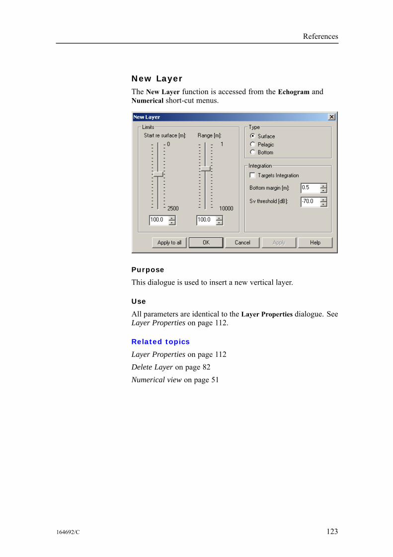
References
New LayerThe New Layer function is accessed from the Echogram andNumerical short-cut menus.
Purpose
This dialogue is used to insert a new vertical layer.
Use
All parameters are identical to the Layer Properties dialogue. SeeLayer Properties on page 112.
Related topics
Layer Properties on page 112Delete Layer on page 82Numerical view on page 51
164692/C 123
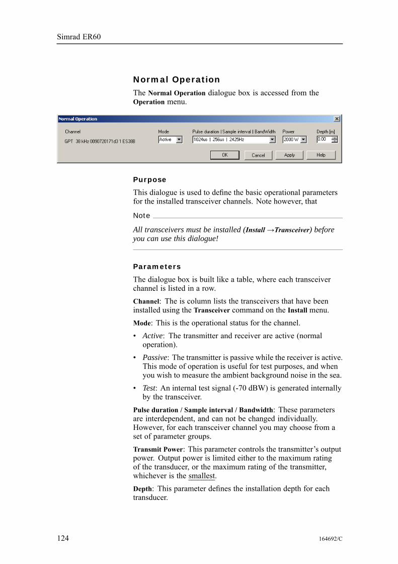
Simrad ER60
Normal OperationThe Normal Operation dialogue box is accessed from theOperation menu.
Purpose
This dialogue is used to define the basic operational parametersfor the installed transceiver channels. Note however, that
Note
All transceivers must be installed (Install →Transceiver) beforeyou can use this dialogue!
Parameters
The dialogue box is built like a table, where each transceiverchannel is listed in a row.Channel: The is column lists the transceivers that have beeninstalled using the Transceiver command on the Install menu.Mode: This is the operational status for the channel.• Active: The transmitter and receiver are active (normaloperation).
• Passive: The transmitter is passive while the receiver is active.This mode of operation is useful for test purposes, and whenyou wish to measure the ambient background noise in the sea.
• Test: An internal test signal (-70 dBW) is generated internallyby the transceiver.
Pulse duration / Sample interval / Bandwidth: These parametersare interdependent, and can not be changed individually.However, for each transceiver channel you may choose from aset of parameter groups.Transmit Power: This parameter controls the transmitter’s outputpower. Output power is limited either to the maximum ratingof the transducer, or the maximum rating of the transmitter,whichever is the smallest.Depth: This parameter defines the installation depth for eachtransducer.
124 164692/C
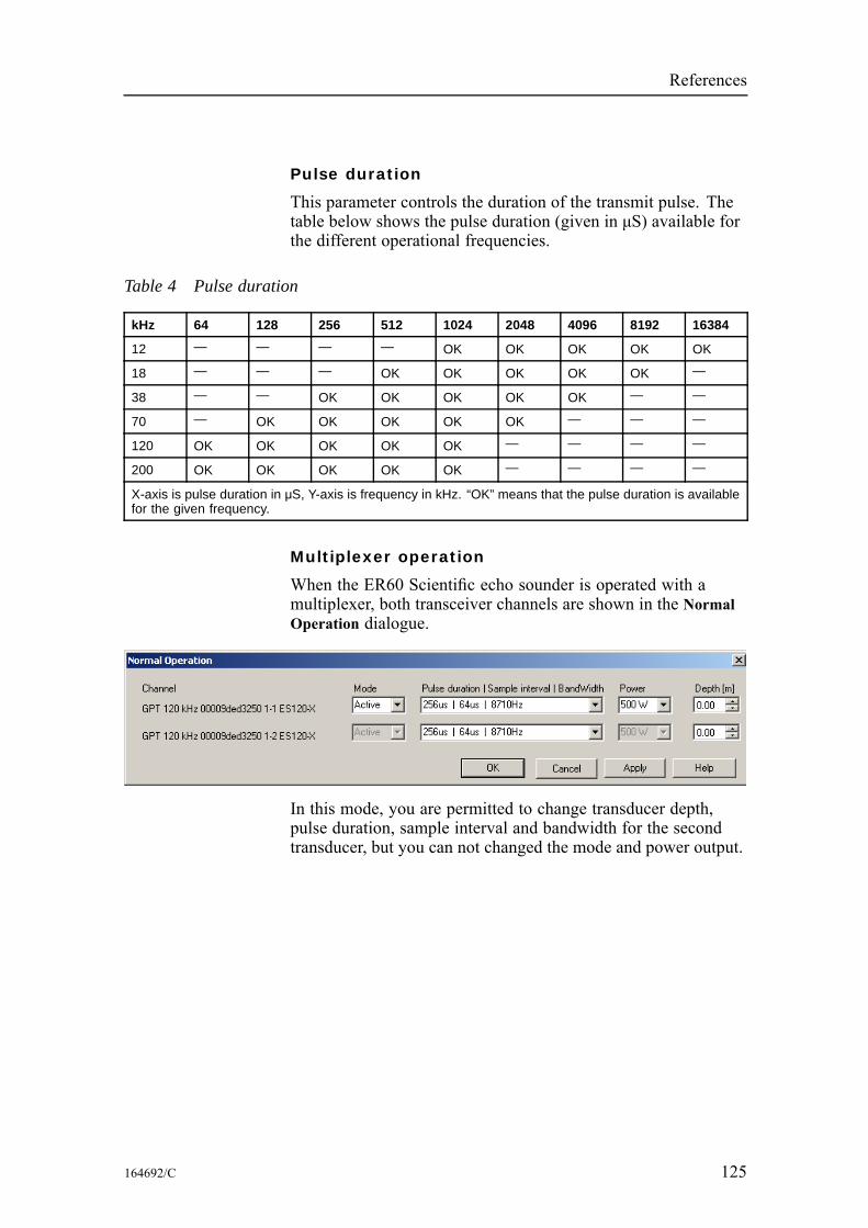
References
Pulse duration
This parameter controls the duration of the transmit pulse. Thetable below shows the pulse duration (given in μS) available forthe different operational frequencies.
Table 4 Pulse duration
kHz 64 128 256 512 1024 2048 4096 8192 16384
12 — — — — OK OK OK OK OK
18 — — — OK OK OK OK OK —
38 — — OK OK OK OK OK — —
70 — OK OK OK OK OK — — —
120 OK OK OK OK OK — — — —
200 OK OK OK OK OK — — — —
X-axis is pulse duration in μS, Y-axis is frequency in kHz. “OK” means that the pulse duration is availablefor the given frequency.
Multiplexer operation
When the ER60 Scientific echo sounder is operated with amultiplexer, both transceiver channels are shown in the NormalOperation dialogue.
In this mode, you are permitted to change transducer depth,pulse duration, sample interval and bandwidth for the secondtransducer, but you can not changed the mode and power output.
164692/C 125
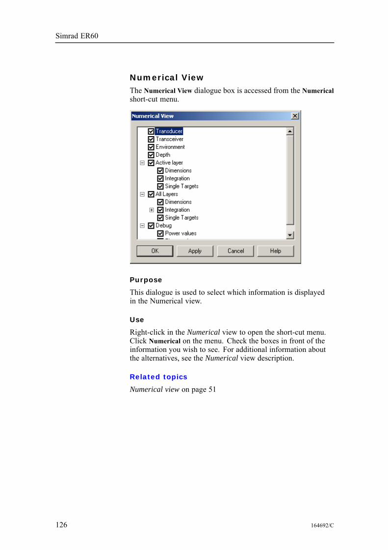
Simrad ER60
Numerical ViewThe Numerical View dialogue box is accessed from the Numericalshort-cut menu.
Purpose
This dialogue is used to select which information is displayedin the Numerical view.
Use
Right-click in the Numerical view to open the short-cut menu.Click Numerical on the menu. Check the boxes in front of theinformation you wish to see. For additional information aboutthe alternatives, see the Numerical view description.
Related topics
Numerical view on page 51
126 164692/C
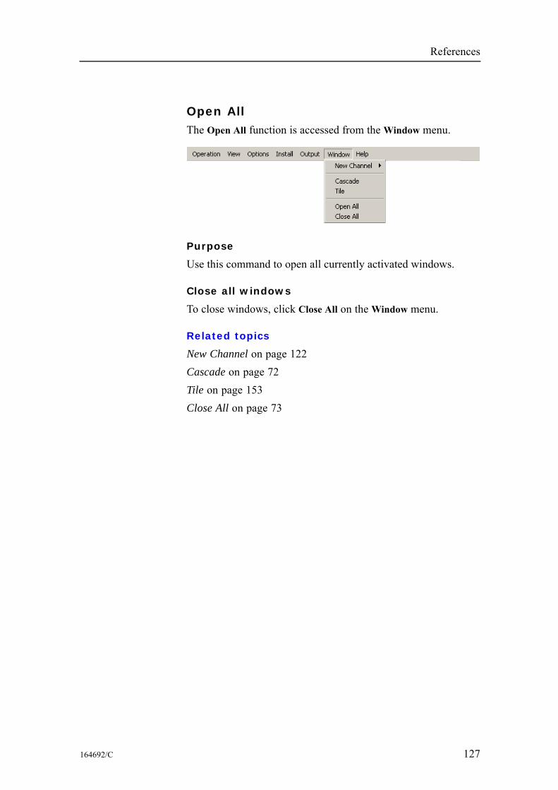
References
Open AllThe Open All function is accessed from theWindow menu.
Purpose
Use this command to open all currently activated windows.
Close all windows
To close windows, click Close All on theWindow menu.
Related topics
New Channel on page 122Cascade on page 72Tile on page 153Close All on page 73
164692/C 127
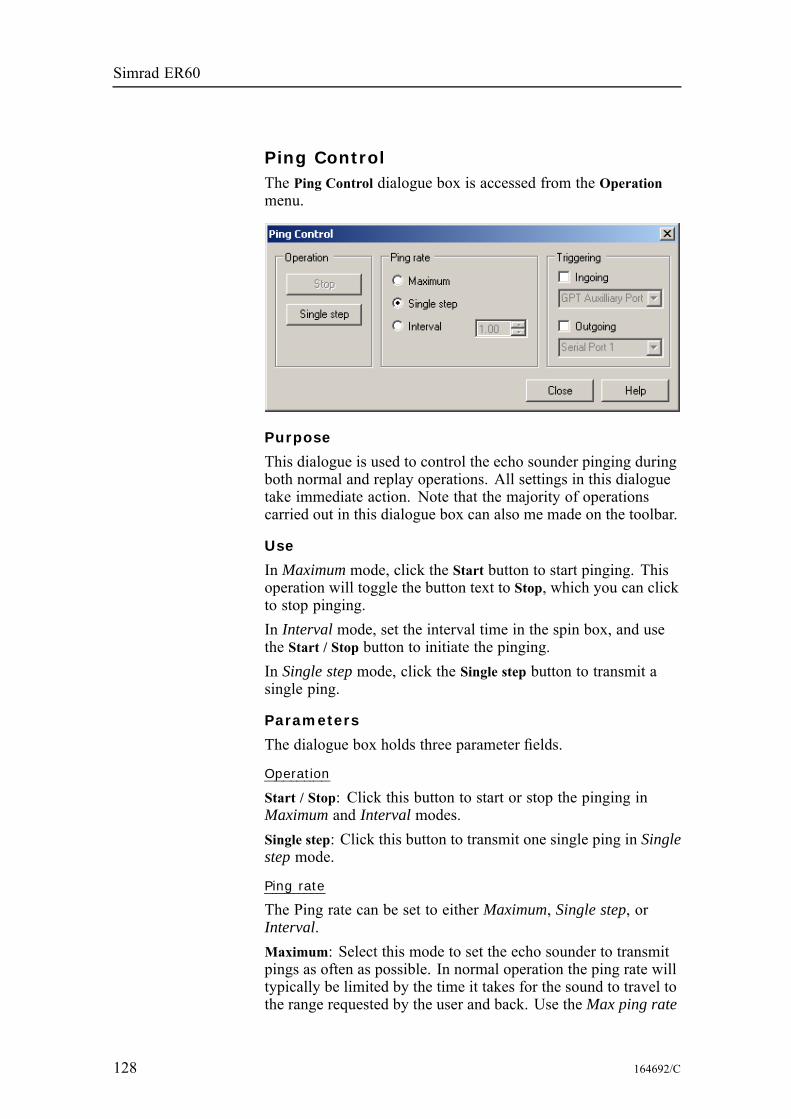
Simrad ER60
Ping ControlThe Ping Control dialogue box is accessed from the Operationmenu.
Purpose
This dialogue is used to control the echo sounder pinging duringboth normal and replay operations. All settings in this dialoguetake immediate action. Note that the majority of operationscarried out in this dialogue box can also me made on the toolbar.
Use
In Maximum mode, click the Start button to start pinging. Thisoperation will toggle the button text to Stop, which you can clickto stop pinging.In Interval mode, set the interval time in the spin box, and usethe Start / Stop button to initiate the pinging.In Single step mode, click the Single step button to transmit asingle ping.
Parameters
The dialogue box holds three parameter fields.
Operation
Start / Stop: Click this button to start or stop the pinging inMaximum and Interval modes.Single step: Click this button to transmit one single ping in Singlestep mode.
Ping rate
The Ping rate can be set to either Maximum, Single step, orInterval.Maximum: Select this mode to set the echo sounder to transmitpings as often as possible. In normal operation the ping rate willtypically be limited by the time it takes for the sound to travel tothe range requested by the user and back. Use the Max ping rate
128 164692/C
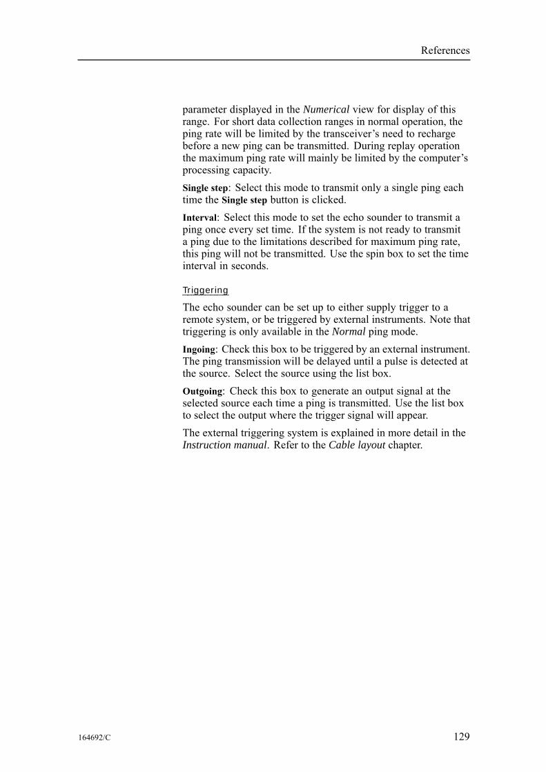
References
parameter displayed in the Numerical view for display of thisrange. For short data collection ranges in normal operation, theping rate will be limited by the transceiver’s need to rechargebefore a new ping can be transmitted. During replay operationthe maximum ping rate will mainly be limited by the computer’sprocessing capacity.Single step: Select this mode to transmit only a single ping eachtime the Single step button is clicked.Interval: Select this mode to set the echo sounder to transmit aping once every set time. If the system is not ready to transmita ping due to the limitations described for maximum ping rate,this ping will not be transmitted. Use the spin box to set the timeinterval in seconds.
Triggering
The echo sounder can be set up to either supply trigger to aremote system, or be triggered by external instruments. Note thattriggering is only available in the Normal ping mode.Ingoing: Check this box to be triggered by an external instrument.The ping transmission will be delayed until a pulse is detected atthe source. Select the source using the list box.Outgoing: Check this box to generate an output signal at theselected source each time a ping is transmitted. Use the list boxto select the output where the trigger signal will appear.The external triggering system is explained in more detail in theInstruction manual. Refer to the Cable layout chapter.
164692/C 129
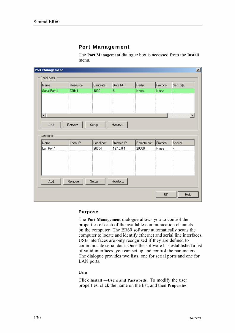
Simrad ER60
Port ManagementThe Port Management dialogue box is accessed from the Installmenu.
Purpose
The Port Management dialogue allows you to control theproperties of each of the available communication channelson the computer. The ER60 software automatically scans thecomputer to locate and identify ethernet and serial line interfaces.USB interfaces are only recognized if they are defined tocommunicate serial data. Once the software has established a listof valid interfaces, you can set up and control the parameters.The dialogue provides two lists, one for serial ports and one forLAN ports.
Use
Click Install →Users and Passwords. To modify the userproperties, click the name on the list, and then Properties.
130 164692/C
References
Parameters
Serial ports
Protocol: Each serial line can communicate with more than onesensor simultaneously provided that each sensor use the sameprotocol.Sensors: This column is used to identify the external sensorcurrently connected to the serial line.Add: If you have added additional serial lines to the computer(for example by installing an extra interface circuit board), youcan click Add to identify the new ports. If you have previouslyreleased an unused serial port, but wish to bring it back to ER60use, you must also press Add to include it.Remove: Once the ER60 has identified and listed all the availableserial lines on the computer, these can not be used by any othersoftware applications on the same computer. However, if theER60 does not need a specific serial line, it can be released forother use when you select it and press the Remove button.Setup: Select a serial line and press the Setup button to definethe communication parameters.Monitor: Select a serial line and press theMonitor button to openthe Port Monitor dialogue. This feature allows you to monitor thetraffic on the serial line.
LAN ports
Local IP: This is the IP number of the network card in yourcomputer that you wish to use.Local port: This is local port you wish to use.Remote IP: This is the IP number of a remote computer.For point-to-point communication, you must define this IPaddress. If you wish to broadcast information, enter IP number255.255.255.255. For inputs, you do not need to set up thisparameter.Remote port: Set up the remote port only if applicable forpoint-to-point data export.Protocol: Each ethernet line can communicate with more thanone sensor simultaneously provided that each sensor use thesame protocol.Sensors: This column is used to identify the external sensorcurrently connected to the serial line.Add: If you wish to assign a new port to the existing networkcard, or add a new network card, press Add to identify the newport(s).Remove: Use this feature to remove ports you do not need.
164692/C 131

Simrad ER60
Setup: Select a LAN port and press the Setup button to definethe communication parameters.Monitor: Select a LAN port and press theMonitor button to openthe Port Monitor dialogue. This feature allows you to monitor thetraffic on the LAN port.
Related topics
Serial Port Setup on page 147LAN Port Setup on page 111Port Monitor on page 133
132 164692/C
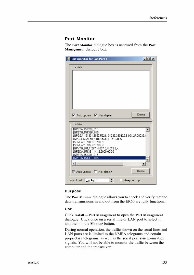
References
Port MonitorThe Port Monitor dialogue box is accessed from the PortManagement dialogue box.
Purpose
The Port Monitor dialogue allows you to check and verify that thedata transmissions in and out from the ER60 are fully functional.
Use
Click Install →Port Management to open the Port Managementdialogue. Click once on a serial line or LAN port to select it,and then on the Monitor button.During normal operation, the traffic shown on the serial lines andLAN ports are is limited to the NMEA telegrams and certainproprietary telegrams, as well as the serial port synchronisationsignals. You will not be able to monitor the traffic between thecomputer and the transceiver.
164692/C 133
Simrad ER60
During replay, the NMEA telegrams and certain proprietarytelegrams stored in the raw data file are shown on the LAN ports.
Parameters
Tx data
Text window: The text window is used to display the datacommunication transmitted from the ER60.Auto update: Check this box to allow the information in the textwindow to be automatically updated.Hex display: Check this box to have the data communicationpresented in hex format.Delete: Click this button to clear the text window.
Rx data
Text window: The text window is used to display the datacommunication received by the ER60.Auto update: Check this box to allow the information in the textwindow to be automatically updated.Hex display: Check this box to have the data communicationpresented in hex format.Delete: Click this button to clear the text window.
Other parameters
Current port: You can use this spin box to select an other serialline or LAN port. This allows you to choose an other port withoutreturning to the Port Management dialogue.Always on top: Check this box if you with the dialogue to stay ontop of the echo sounder windows. You are not recommended touse this feature during normal operations.
Related topics
Serial Port Setup on page 147LAN Port Setup on page 111Port Management on page 130
134 164692/C
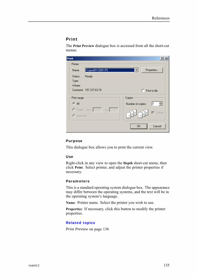
References
PrintThe Print Preview dialogue box is accessed from all the short-cutmenus.
Purpose
This dialogue box allows you to print the current view.
Use
Right-click in any view to open the Depth short-cut menu, thenclick Print. Select printer, and adjust the printer properties ifnecessary.
Parameters
This is a standard operating system dialogue box. The appearancemay differ between the operating systems, and the text will be inthe operating system’s language.Name: Printer name. Select the printer you wish to use.Properties: If necessary, click this button to modify the printerproperties.
Related topics
Print Preview on page 136
164692/C 135
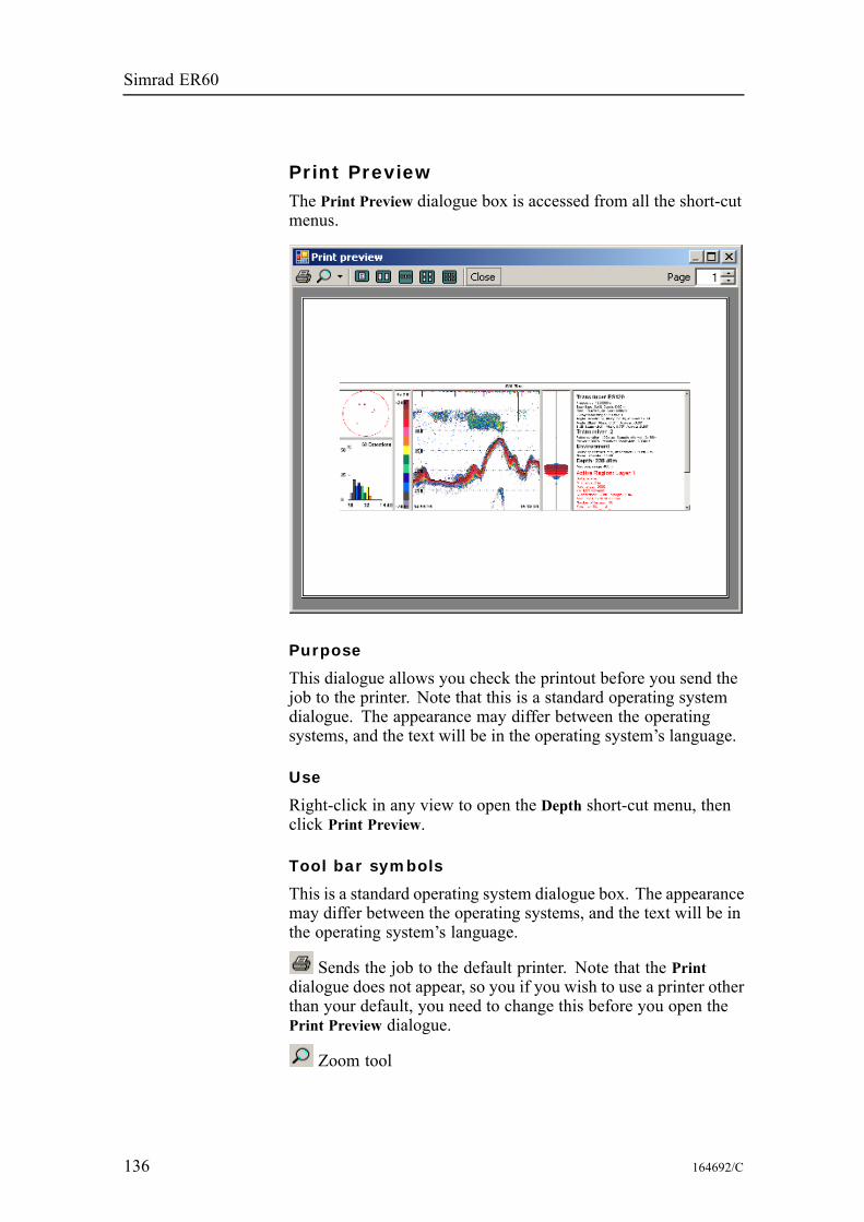
Simrad ER60
Print PreviewThe Print Preview dialogue box is accessed from all the short-cutmenus.
Purpose
This dialogue allows you check the printout before you send thejob to the printer. Note that this is a standard operating systemdialogue. The appearance may differ between the operatingsystems, and the text will be in the operating system’s language.
Use
Right-click in any view to open the Depth short-cut menu, thenclick Print Preview.
Tool bar symbols
This is a standard operating system dialogue box. The appearancemay differ between the operating systems, and the text will be inthe operating system’s language.
Sends the job to the default printer. Note that the Printdialogue does not appear, so you if you wish to use a printer otherthan your default, you need to change this before you open thePrint Preview dialogue.
Zoom tool
136 164692/C
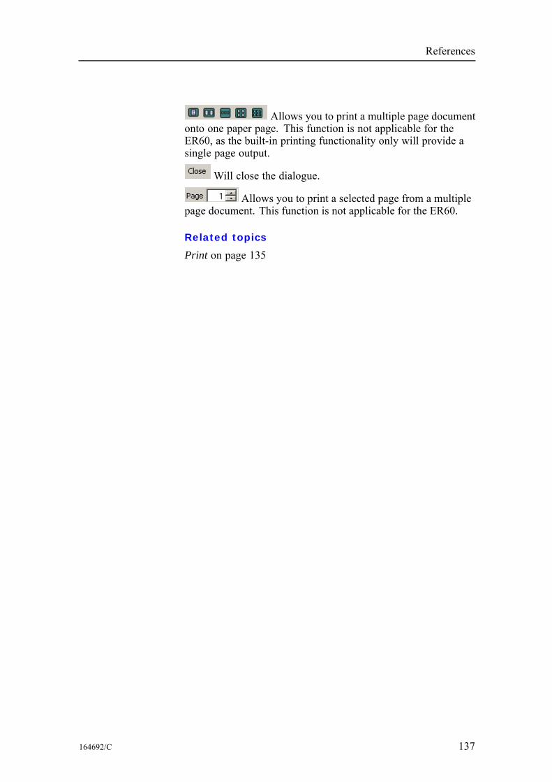
References
Allows you to print a multiple page documentonto one paper page. This function is not applicable for theER60, as the built-in printing functionality only will provide asingle page output.
Will close the dialogue.
Allows you to print a selected page from a multiplepage document. This function is not applicable for the ER60.
Related topics
Print on page 135
164692/C 137
Simrad ER60
RangeThe Range dialogue boxes are accessed from the Echogramshort-cut menu.The dialogue title and the range settings will be surface relatedif the dialogue is opened while the echogram displays a surfacereferenced echogram.The dialogue title and the range settings will be bottom relatedif the dialogue is opened while the echogram displays a bottomreferenced echogram.
Related topics
Bottom Range on page 69Surface Range on page 151
138 164692/C
References
RemotingThe Remoting dialogue box is accessed from the Install menu.
Purpose
This dialogue controls setting of parameters related to remoteoperation of the echo sounder. With these parameters, you canoperate the echo sounder from an other computer connected tothe network. The dialogue provides two tabs:• Server• Client
Use
Click Install→Remoting. Click one of the two tabs, and make thenecessary adjustments.
Related topics
Data Source on page 80
164692/C 139
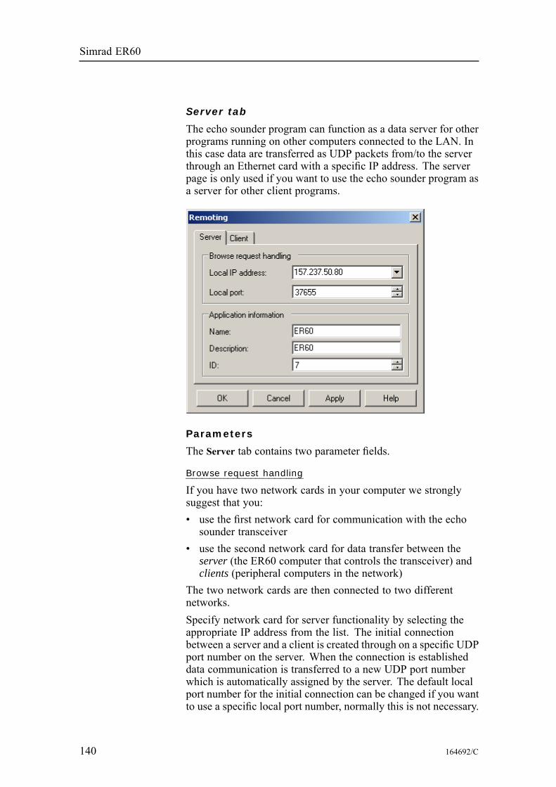
Simrad ER60
Server tab
The echo sounder program can function as a data server for otherprograms running on other computers connected to the LAN. Inthis case data are transferred as UDP packets from/to the serverthrough an Ethernet card with a specific IP address. The serverpage is only used if you want to use the echo sounder program asa server for other client programs.
Parameters
The Server tab contains two parameter fields.
Browse request handling
If you have two network cards in your computer we stronglysuggest that you:• use the first network card for communication with the echosounder transceiver
• use the second network card for data transfer between theserver (the ER60 computer that controls the transceiver) andclients (peripheral computers in the network)
The two network cards are then connected to two differentnetworks.Specify network card for server functionality by selecting theappropriate IP address from the list. The initial connectionbetween a server and a client is created through on a specific UDPport number on the server. When the connection is establisheddata communication is transferred to a new UDP port numberwhich is automatically assigned by the server. The default localport number for the initial connection can be changed if you wantto use a specific local port number, normally this is not necessary.
140 164692/C

References
Local IP address: Choose the IP address of the network card inyour computer that shall communicate with other clients.Local port: Define the port on the computer. Unless specialrequirements dictate otherwise, use 37655. This is the defaultvalue.
Application information
When the server application (the ER60 Scientific echo sounder)exposes itself it exposes various application information. Thedescription and ID exposed can be set here.
164692/C 141
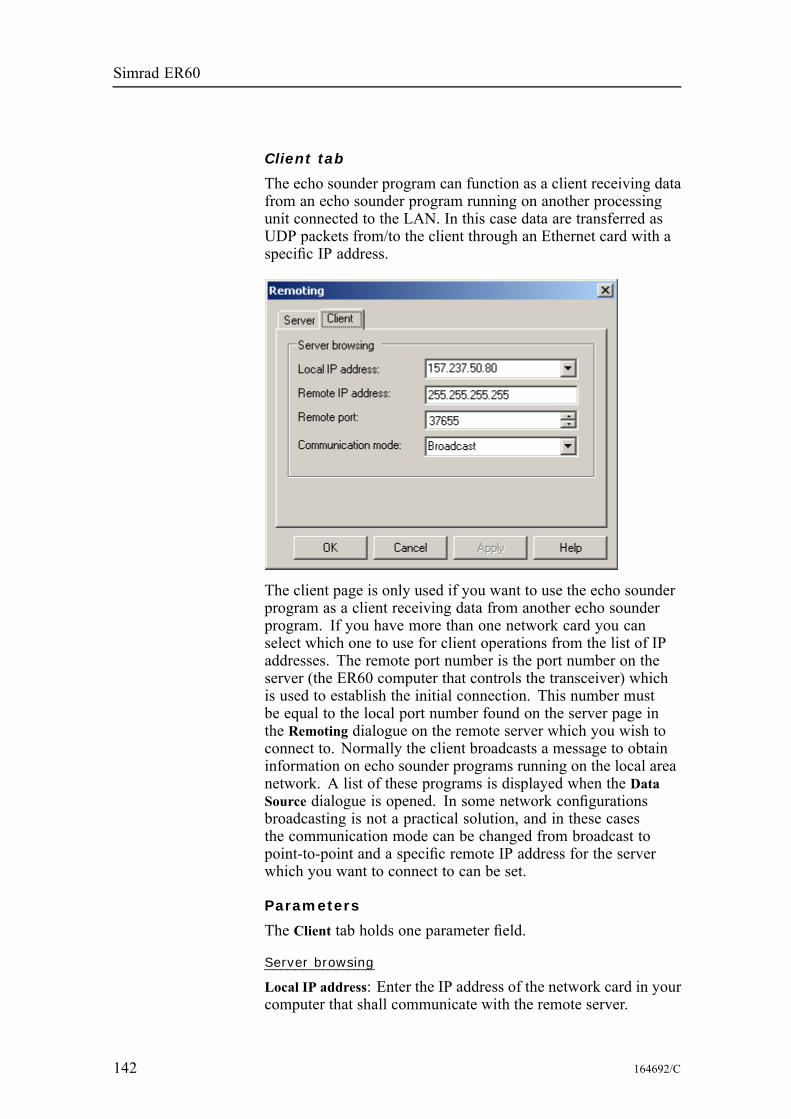
Simrad ER60
Client tab
The echo sounder program can function as a client receiving datafrom an echo sounder program running on another processingunit connected to the LAN. In this case data are transferred asUDP packets from/to the client through an Ethernet card with aspecific IP address.
The client page is only used if you want to use the echo sounderprogram as a client receiving data from another echo sounderprogram. If you have more than one network card you canselect which one to use for client operations from the list of IPaddresses. The remote port number is the port number on theserver (the ER60 computer that controls the transceiver) whichis used to establish the initial connection. This number mustbe equal to the local port number found on the server page inthe Remoting dialogue on the remote server which you wish toconnect to. Normally the client broadcasts a message to obtaininformation on echo sounder programs running on the local areanetwork. A list of these programs is displayed when the DataSource dialogue is opened. In some network configurationsbroadcasting is not a practical solution, and in these casesthe communication mode can be changed from broadcast topoint-to-point and a specific remote IP address for the serverwhich you want to connect to can be set.
Parameters
The Client tab holds one parameter field.
Server browsing
Local IP address: Enter the IP address of the network card in yourcomputer that shall communicate with the remote server.
142 164692/C

References
Remote IP address: Enter the IP address of the remote server.Remote port: Enter the port number used on the remote server.Communication mode: Choose Broadcast or Point-to-pointdepending on the data distribution requirements.
164692/C 143
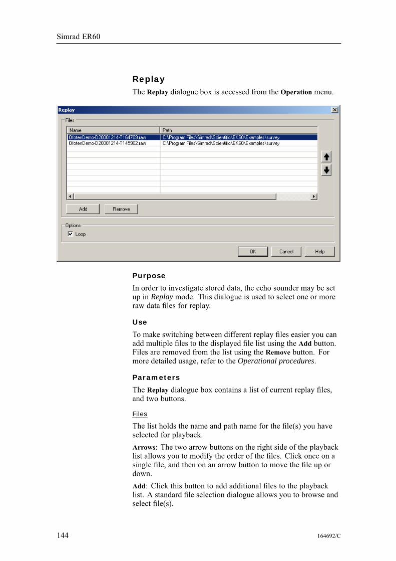
Simrad ER60
ReplayThe Replay dialogue box is accessed from the Operation menu.
Purpose
In order to investigate stored data, the echo sounder may be setup in Replay mode. This dialogue is used to select one or moreraw data files for replay.
Use
To make switching between different replay files easier you canadd multiple files to the displayed file list using the Add button.Files are removed from the list using the Remove button. Formore detailed usage, refer to the Operational procedures.
Parameters
The Replay dialogue box contains a list of current replay files,and two buttons.
Files
The list holds the name and path name for the file(s) you haveselected for playback.Arrows: The two arrow buttons on the right side of the playbacklist allows you to modify the order of the files. Click once on asingle file, and then on an arrow button to move the file up ordown.Add: Click this button to add additional files to the playbacklist. A standard file selection dialogue allows you to browse andselect file(s).
144 164692/C

References
Remove: Click on a file name in the playback list, and then clickthis button to remove the file from the list. This button will notdelete the file from the hard disk.
Options
Loop: Click to enable continuous playback of the file(s) in theplayback list.
164692/C 145
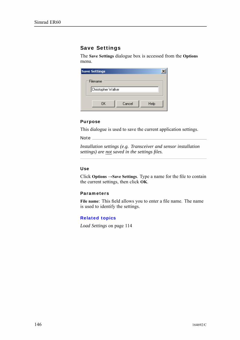
Simrad ER60
Save SettingsThe Save Settings dialogue box is accessed from the Optionsmenu.
Purpose
This dialogue is used to save the current application settings.
Note
Installation settings (e.g. Transceiver and sensor installationsettings) are not saved in the settings files.
Use
Click Options→Save Settings. Type a name for the file to containthe current settings, then click OK.
Parameters
File name: This field allows you to enter a file name. The nameis used to identify the settings.
Related topics
Load Settings on page 114
146 164692/C
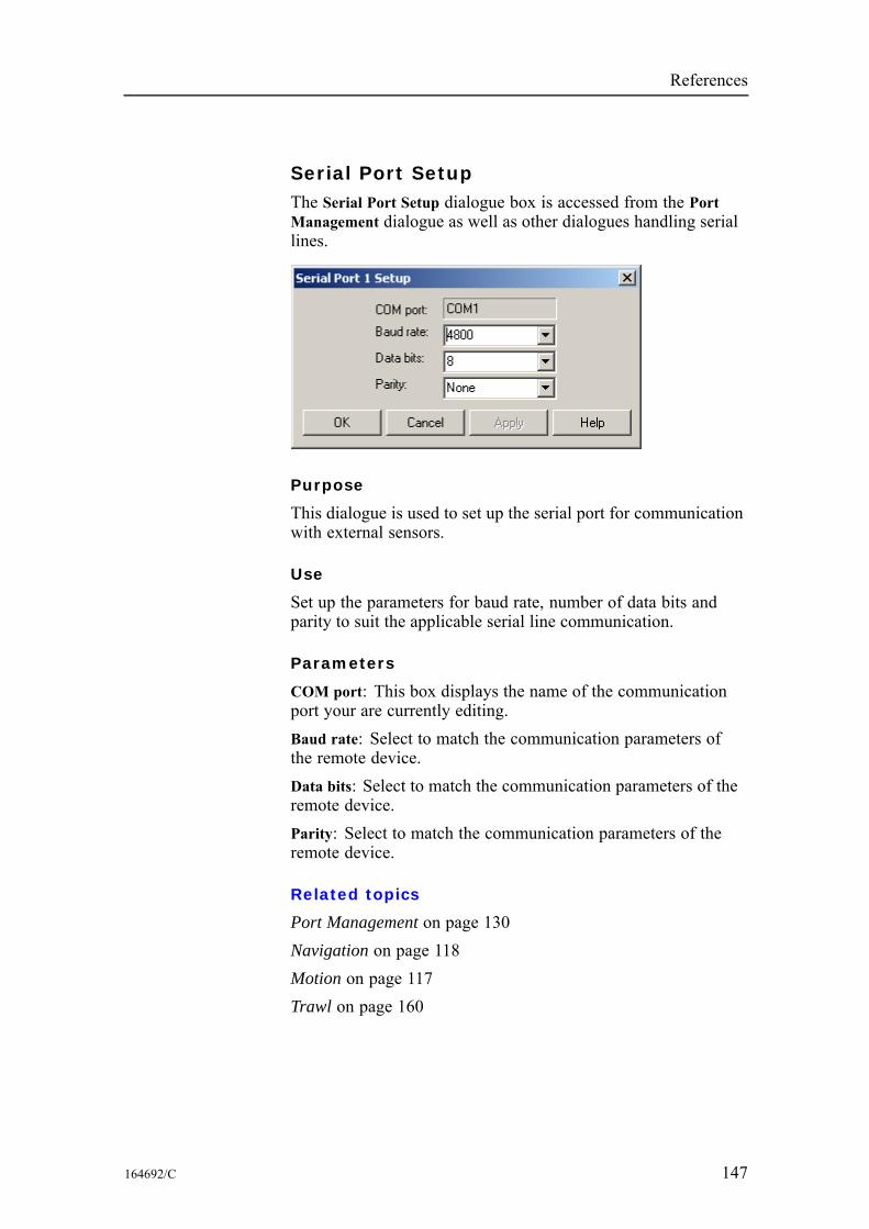
References
Serial Port SetupThe Serial Port Setup dialogue box is accessed from the PortManagement dialogue as well as other dialogues handling seriallines.
Purpose
This dialogue is used to set up the serial port for communicationwith external sensors.
Use
Set up the parameters for baud rate, number of data bits andparity to suit the applicable serial line communication.
Parameters
COM port: This box displays the name of the communicationport your are currently editing.Baud rate: Select to match the communication parameters ofthe remote device.Data bits: Select to match the communication parameters of theremote device.Parity: Select to match the communication parameters of theremote device.
Related topics
Port Management on page 130Navigation on page 118Motion on page 117Trawl on page 160
164692/C 147
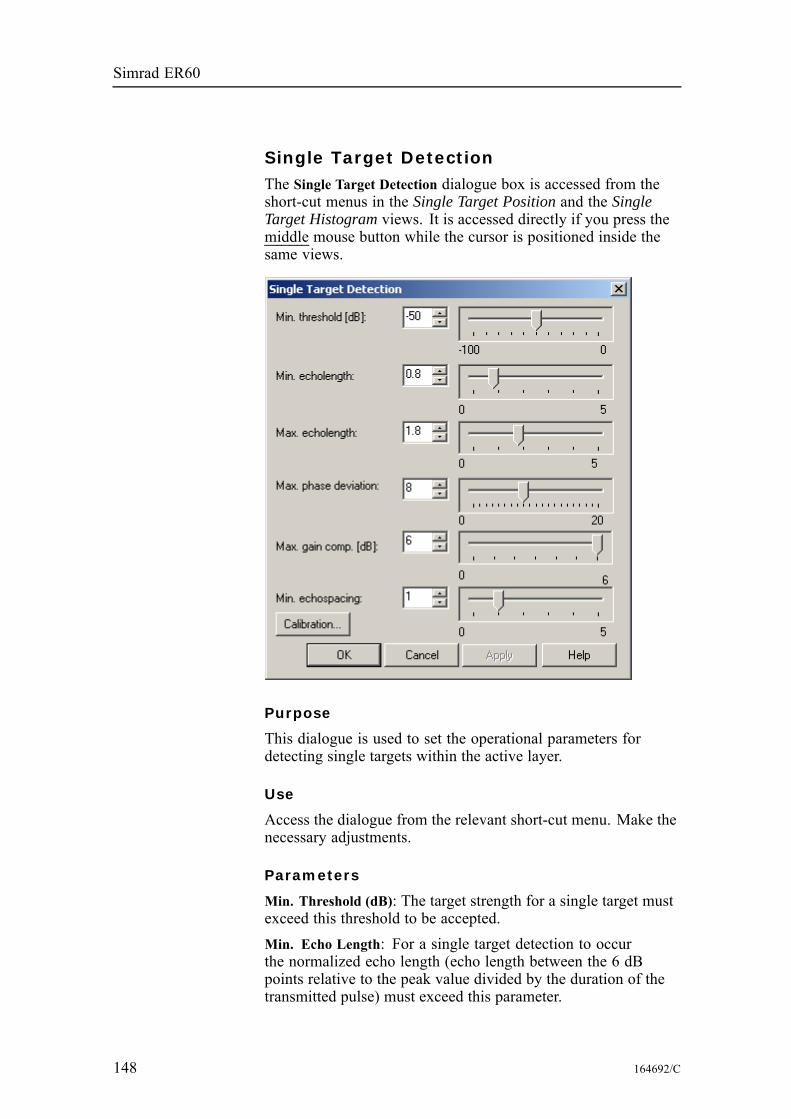
Simrad ER60
Single Target DetectionThe Single Target Detection dialogue box is accessed from theshort-cut menus in the Single Target Position and the SingleTarget Histogram views. It is accessed directly if you press themiddle mouse button while the cursor is positioned inside thesame views.
Purpose
This dialogue is used to set the operational parameters fordetecting single targets within the active layer.
Use
Access the dialogue from the relevant short-cut menu. Make thenecessary adjustments.
Parameters
Min. Threshold (dB): The target strength for a single target mustexceed this threshold to be accepted.Min. Echo Length: For a single target detection to occurthe normalized echo length (echo length between the 6 dBpoints relative to the peak value divided by the duration of thetransmitted pulse) must exceed this parameter.
148 164692/C
References
Max. Echo Length: A single target detection requires thenormalized echo length to be less than the maximum echo lengthsetting.Max. Phase Deviation: Average electrical phase jitter betweensamples inside an echo from a single target must not exceedthe maximum phase deviation setting where maximum phasedeviation is set in units of phase steps (128 phase steps = 180electrical degrees). Recommended setting is 2 to 3 for normalconditions. For weak echoes in noisy conditions you shouldallow for more jitter (4 to 10).Max. Gain Compensation: The correction value returned fromthe transducer gain model must not exceed the maximum gaincompensation setting. (This is the one-way maximum gaincompensation. The two-way maximum compensation will be 12dB). All single targets outside the angle corresponding to thechosen gain compensation are skipped. Thus you can reducethe sample volume (beam angle) by choosing a lower value formaximum gain compensation.Min. Echo Spacing: The is the minimum spacing between twosingle echoes required for acceptance.
Calibration
Click the Calibration button to start the dedicated calibrationprogram with single target detections for this layer.Note that you must click the Apply button before you start thecalibration program if you have made changes to the single targetdetection parameters. This is to ensure that the parameters havebeen applied for the layer.
Related topics
Single target histogram view on page 47Single target position view on page 46Calibration on page 19
164692/C 149
Simrad ER60
Status barThe Status bar function is accessed from the View menu.
Purpose
This is simply an “on/off” switch to show or hide the status bar.When enabled, the status bar will appear at the bottom of theecho sounder window.
Use
Click View→Status bar to enable the status bar.To remove the status bar, repeat the sequence.
Related topics
Status bar on page 43
150 164692/C
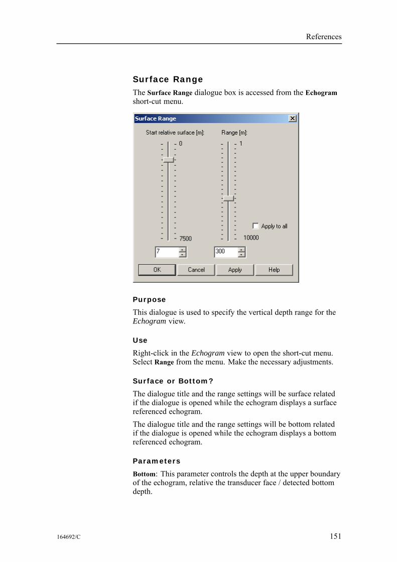
References
Surface RangeThe Surface Range dialogue box is accessed from the Echogramshort-cut menu.
Purpose
This dialogue is used to specify the vertical depth range for theEchogram view.
Use
Right-click in the Echogram view to open the short-cut menu.Select Range from the menu. Make the necessary adjustments.
Surface or Bottom?
The dialogue title and the range settings will be surface relatedif the dialogue is opened while the echogram displays a surfacereferenced echogram.The dialogue title and the range settings will be bottom relatedif the dialogue is opened while the echogram displays a bottomreferenced echogram.
Parameters
Bottom: This parameter controls the depth at the upper boundaryof the echogram, relative the transducer face / detected bottomdepth.
164692/C 151

Simrad ER60
Range: This parameter controls the vertical depth range acrossthe echogram view. Note that positive is always downwards.This means that a start range relative bottom of -10 m means 10m above bottom!Apply to all: Check this box to apply the new range setting to allcurrent surface and bottom echograms.
Related topics
Bottom Range on page 69Echogram view on page 48
152 164692/C
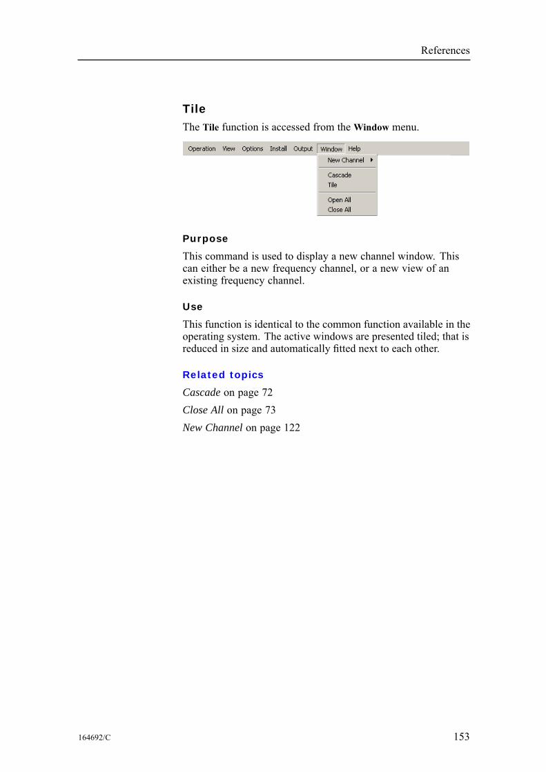
References
TileThe Tile function is accessed from theWindow menu.
Purpose
This command is used to display a new channel window. Thiscan either be a new frequency channel, or a new view of anexisting frequency channel.
Use
This function is identical to the common function available in theoperating system. The active windows are presented tiled; that isreduced in size and automatically fitted next to each other.
Related topics
Cascade on page 72Close All on page 73New Channel on page 122
164692/C 153
Simrad ER60
ToolbarsThe Toolbars function is accessed from the View menu.
Purpose
This is simply an “on/off” switch to show or hide the toolbars.You can choose to open the Normal Operation or the EasyOperation toolbars, or both. When enabled, the toolbars willappear directly below or next to the main menu.
Use
Click View→Toolbars→Normal Operation to enable the NormalOperation toolbar.Click View →Toolbars →Easy Operation to enable the EasyOperation toolbar.To remove a toolbar, repeat the sequence.
Related topics
Toolbar on page 42
154 164692/C
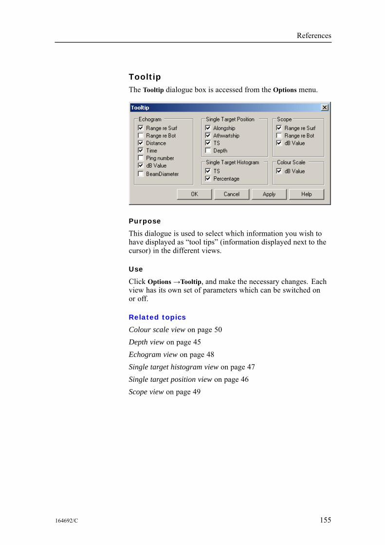
References
TooltipThe Tooltip dialogue box is accessed from the Options menu.
Purpose
This dialogue is used to select which information you wish tohave displayed as “tool tips” (information displayed next to thecursor) in the different views.
Use
Click Options→Tooltip, and make the necessary changes. Eachview has its own set of parameters which can be switched onor off.
Related topics
Colour scale view on page 50Depth view on page 45Echogram view on page 48Single target histogram view on page 47Single target position view on page 46Scope view on page 49
164692/C 155
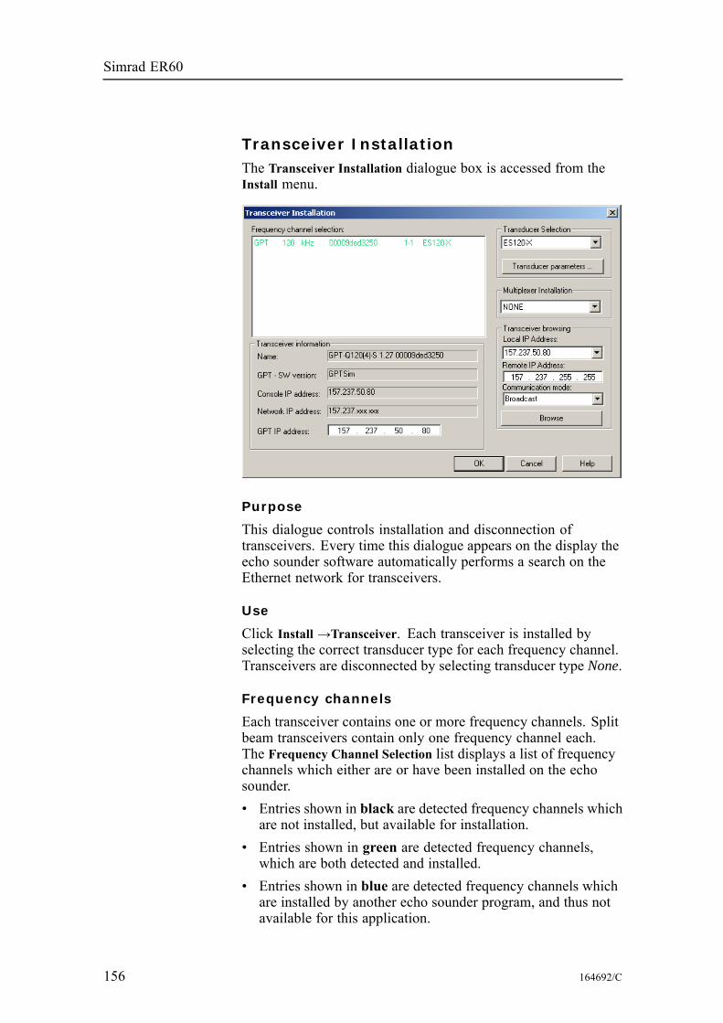
Simrad ER60
Transceiver InstallationThe Transceiver Installation dialogue box is accessed from theInstall menu.
Purpose
This dialogue controls installation and disconnection oftransceivers. Every time this dialogue appears on the display theecho sounder software automatically performs a search on theEthernet network for transceivers.
Use
Click Install →Transceiver. Each transceiver is installed byselecting the correct transducer type for each frequency channel.Transceivers are disconnected by selecting transducer type None.
Frequency channels
Each transceiver contains one or more frequency channels. Splitbeam transceivers contain only one frequency channel each.The Frequency Channel Selection list displays a list of frequencychannels which either are or have been installed on the echosounder.• Entries shown in black are detected frequency channels whichare not installed, but available for installation.
• Entries shown in green are detected frequency channels,which are both detected and installed.
• Entries shown in blue are detected frequency channels whichare installed by another echo sounder program, and thus notavailable for this application.
156 164692/C
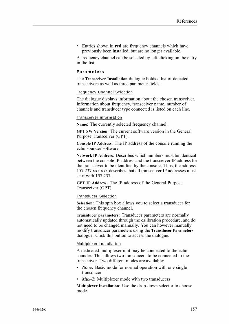
References
• Entries shown in red are frequency channels which havepreviously been installed, but are no longer available.
A frequency channel can be selected by left clicking on the entryin the list.
Parameters
The Transceiver Installation dialogue holds a list of detectedtransceivers as well as three parameter fields.
Frequency Channel Selection
The dialogue displays information about the chosen transceiver.Information about frequency, transceiver name, number ofchannels and transducer type connected is listed on each line.
Transceiver information
Name: The currently selected frequency channel.GPT SW Version: The current software version in the GeneralPurpose Transceiver (GPT).Console IP Address: The IP address of the console running theecho sounder software.Network IP Address: Describes which numbers must be identicalbetween the console IP address and the transceiver IP address forthe transceiver to be identified by the console. Thus, the address157.237.xxx.xxx describes that all transceiver IP addresses muststart with 157.237.GPT IP Address: The IP address of the General PurposeTransceiver (GPT).
Transducer Selection
Selection: This spin box allows you to select a transducer forthe chosen frequency channel.Transducer parameters: Transducer parameters are normallyautomatically updated through the calibration procedure, and donot need to be changed manually. You can however manuallymodify transducer parameters using the Transducer Parametersdialogue. Click this button to access the dialogue.
Multiplexer Installation
A dedicated multiplexer unit may be connected to the echosounder. This allows two transducers to be connected to thetransceiver. Two different modes are available:• None: Basic mode for normal operation with one singletransducer
• Mux-2: Multiplexer mode with two transducersMultiplexer Installation: Use the drop-down selector to choosemode.
164692/C 157
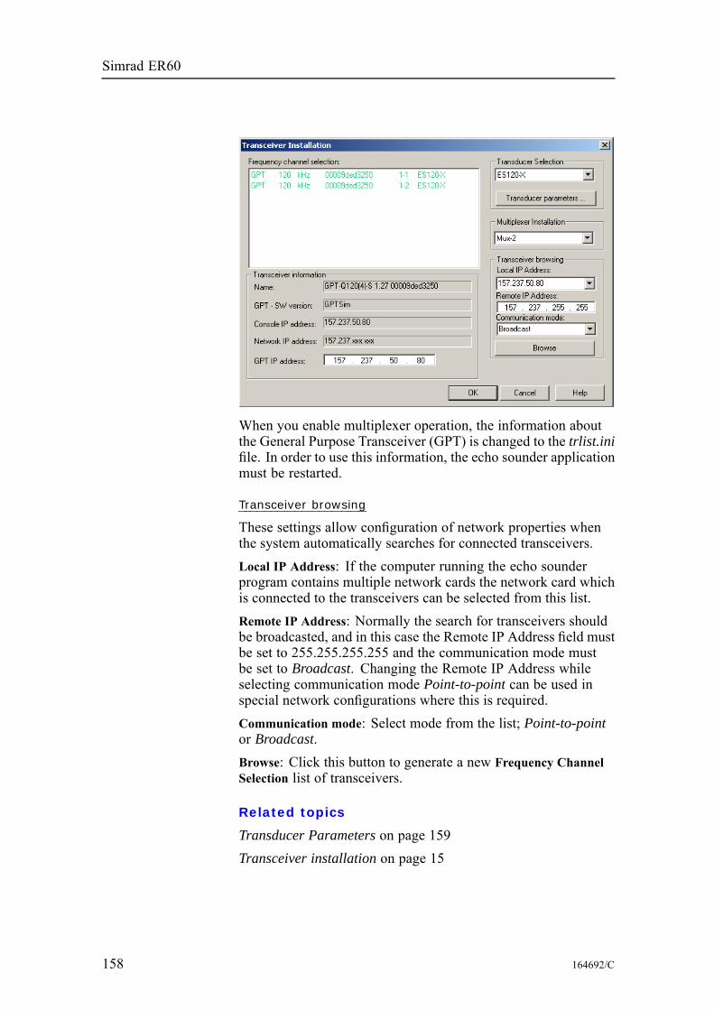
Simrad ER60
When you enable multiplexer operation, the information aboutthe General Purpose Transceiver (GPT) is changed to the trlist.inifile. In order to use this information, the echo sounder applicationmust be restarted.
Transceiver browsing
These settings allow configuration of network properties whenthe system automatically searches for connected transceivers.Local IP Address: If the computer running the echo sounderprogram contains multiple network cards the network card whichis connected to the transceivers can be selected from this list.Remote IP Address: Normally the search for transceivers shouldbe broadcasted, and in this case the Remote IP Address field mustbe set to 255.255.255.255 and the communication mode mustbe set to Broadcast. Changing the Remote IP Address whileselecting communication mode Point-to-point can be used inspecial network configurations where this is required.Communication mode: Select mode from the list; Point-to-pointor Broadcast.Browse: Click this button to generate a new Frequency ChannelSelection list of transceivers.
Related topics
Transducer Parameters on page 159Transceiver installation on page 15
158 164692/C
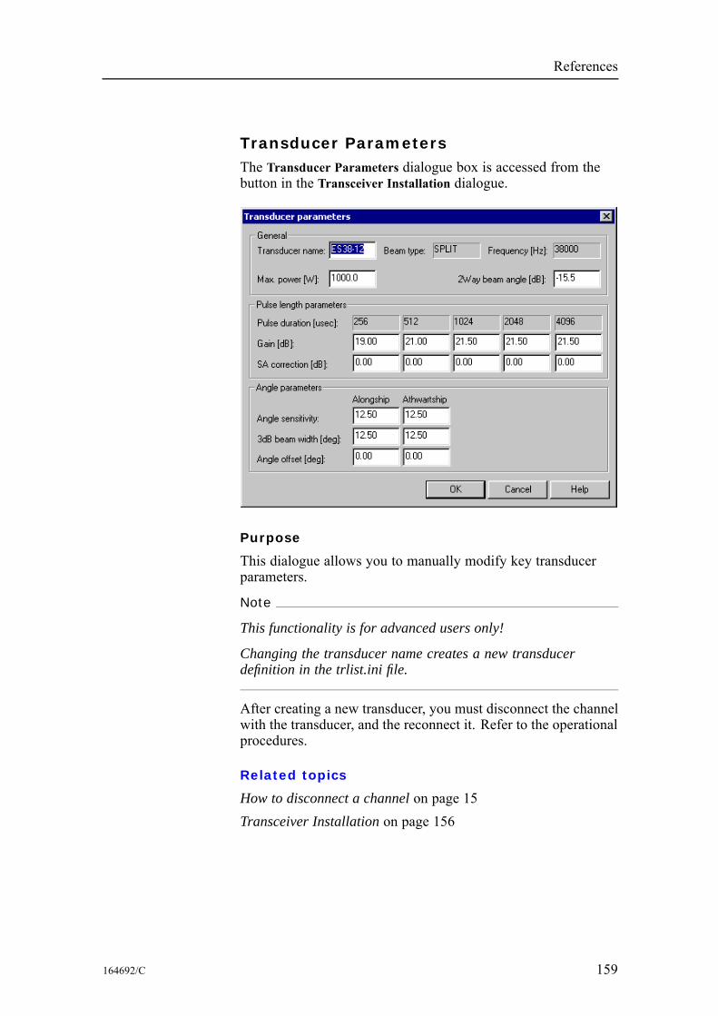
References
Transducer ParametersThe Transducer Parameters dialogue box is accessed from thebutton in the Transceiver Installation dialogue.
Purpose
This dialogue allows you to manually modify key transducerparameters.
Note
This functionality is for advanced users only!
Changing the transducer name creates a new transducerdefinition in the trlist.ini file.
After creating a new transducer, you must disconnect the channelwith the transducer, and the reconnect it. Refer to the operationalprocedures.
Related topics
How to disconnect a channel on page 15Transceiver Installation on page 156
164692/C 159
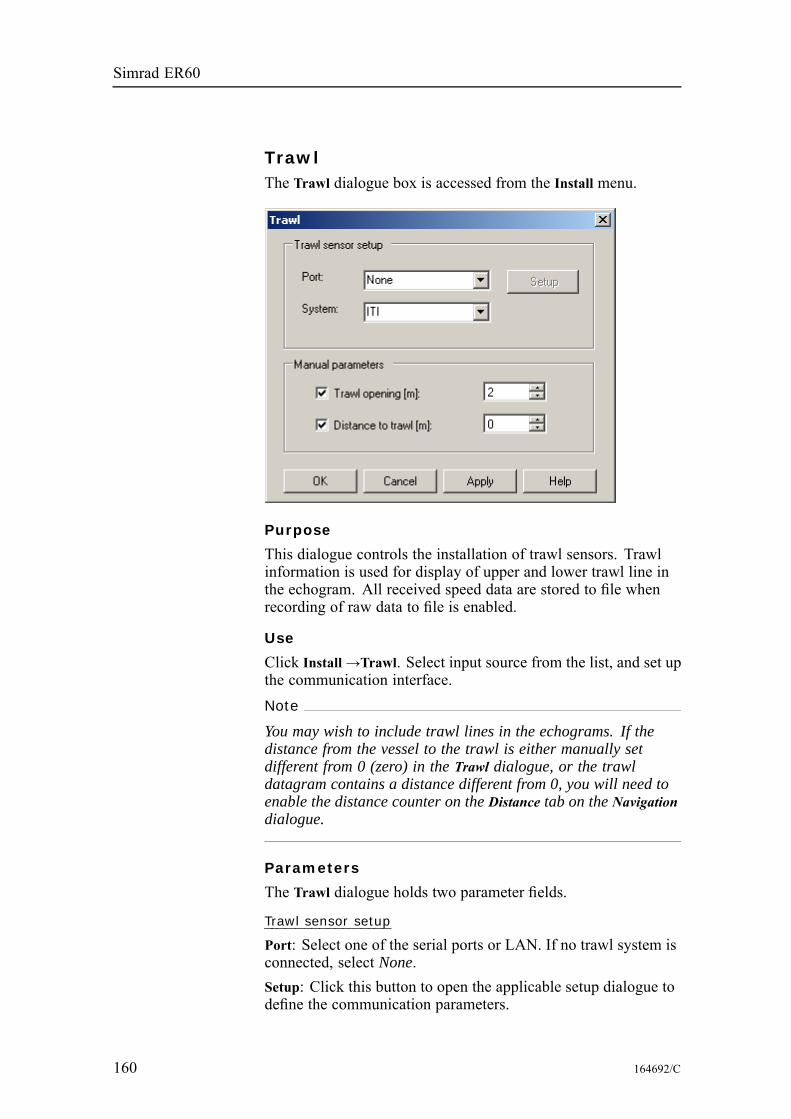
Simrad ER60
TrawlThe Trawl dialogue box is accessed from the Install menu.
Purpose
This dialogue controls the installation of trawl sensors. Trawlinformation is used for display of upper and lower trawl line inthe echogram. All received speed data are stored to file whenrecording of raw data to file is enabled.
Use
Click Install→Trawl. Select input source from the list, and set upthe communication interface.Note
You may wish to include trawl lines in the echograms. If thedistance from the vessel to the trawl is either manually setdifferent from 0 (zero) in the Trawl dialogue, or the trawldatagram contains a distance different from 0, you will need toenable the distance counter on the Distance tab on the Navigationdialogue.
Parameters
The Trawl dialogue holds two parameter fields.
Trawl sensor setup
Port: Select one of the serial ports or LAN. If no trawl system isconnected, select None.Setup: Click this button to open the applicable setup dialogue todefine the communication parameters.
160 164692/C
References
System: Select ITI, PI30 or Ifremer trawl monitoring systems.Other third party systems are not supported.
Manual parameters
If trawl opening and/or distance to trawl information is notautomatically available from a trawl system, the parameters canbe set manually.Trawl opening: Enter the current trawl opening (in meters).Distance to trawl: Enter the current distance between the echosounder transducer and the trawl opening (in meters).
Related topics
Distance tab on page 121Transducer Parameters on page 159Transceiver installation on page 15
164692/C 161
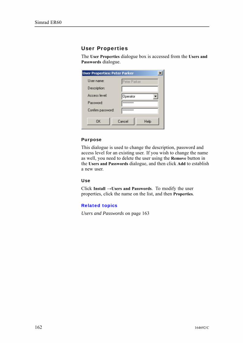
Simrad ER60
User PropertiesThe User Properties dialogue box is accessed from the Users andPasswords dialogue.
Purpose
This dialogue is used to change the description, password andaccess level for an existing user. If you wish to change the nameas well, you need to delete the user using the Remove button inthe Users and Passwords dialogue, and then click Add to establisha new user.
Use
Click Install →Users and Passwords. To modify the userproperties, click the name on the list, and then Properties.
Related topics
Users and Passwords on page 163
162 164692/C
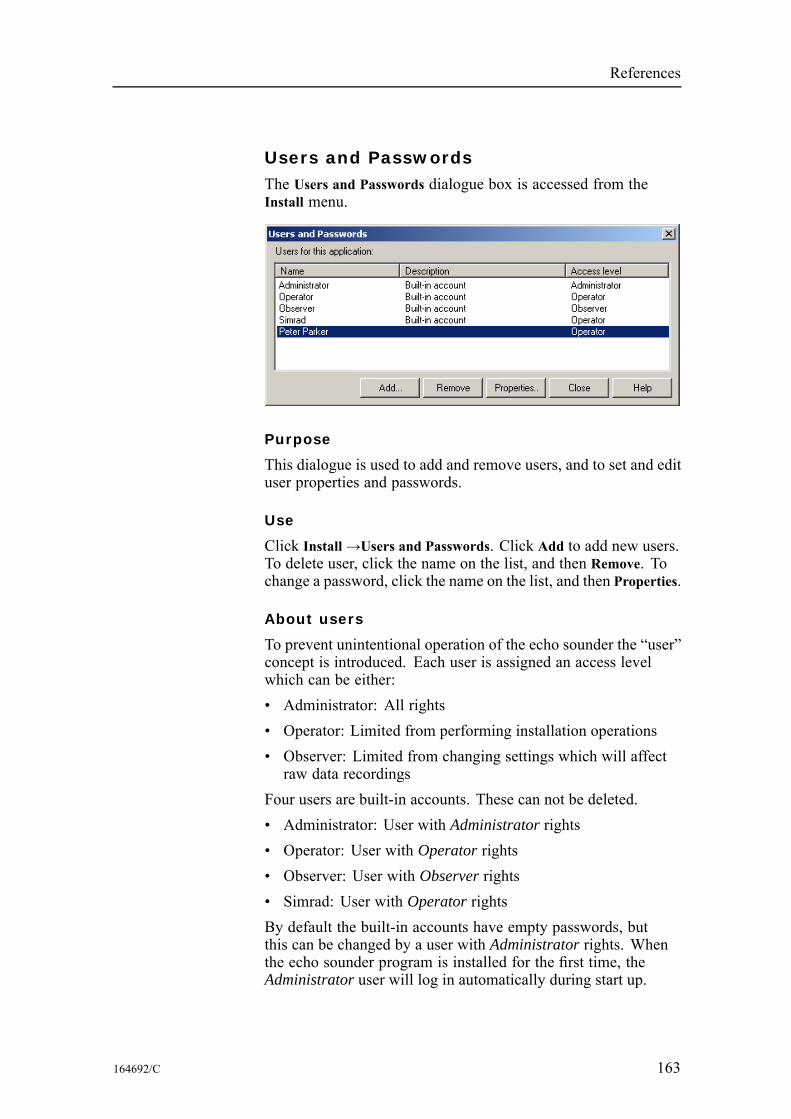
References
Users and PasswordsThe Users and Passwords dialogue box is accessed from theInstall menu.
Purpose
This dialogue is used to add and remove users, and to set and edituser properties and passwords.
Use
Click Install→Users and Passwords. Click Add to add new users.To delete user, click the name on the list, and then Remove. Tochange a password, click the name on the list, and then Properties.
About users
To prevent unintentional operation of the echo sounder the “user”concept is introduced. Each user is assigned an access levelwhich can be either:• Administrator: All rights• Operator: Limited from performing installation operations• Observer: Limited from changing settings which will affectraw data recordings
Four users are built-in accounts. These can not be deleted.• Administrator: User with Administrator rights• Operator: User with Operator rights• Observer: User with Observer rights• Simrad: User with Operator rightsBy default the built-in accounts have empty passwords, butthis can be changed by a user with Administrator rights. Whenthe echo sounder program is installed for the first time, theAdministrator user will log in automatically during start up.
164692/C 163

Simrad ER60
Parameters
List of users
The list of current users hold their names, descriptions and accesslevels. To select a user, click once on the name in the list.
Buttons
Three buttons are provided to maintain the user list.Add: Click to add a new user. The Add User Account dialogueappears to accept user name, description, access level andpassword.Remove: Click to delete the currently select user.Properties: Click to modify the properties of the currently selectuser. The User Properties dialogue appears. It allows you tochange the description, access level and password.
Related topics
Add User Account on page 64User Properties on page 162Log In on page 115Log Out on page 116
164 164692/C
References
WarningsTheWarnings dialogue box is accessed by clicking theWarningsbutton on the Status bar.The same dialogue is also used with other message typespresented by the ER60. Warnings are indicated with a yellowbutton on the Status bar, while errors are indicated with a redbutton. Click the button to open the dialogue.
Purpose
This dialogue will list all the current warning messages fromthe ER60.
Use
Click on the message to read the full text in the text box below thelist. Click Ack to acknowledge the message, or Delete to removeit from the list. If you wish to delete all messages, click Delete all.
Related topics
Status bar on page 43Errors on page 96
164692/C 165
Simrad ER60
DATA FORMATSThis chapter describes how the echo sounder handles dataformats and interfaces.The information contained in this chapter is provided forprogrammers and technical personnel designing third partysoftware to communicate with the Simrad ER60 Scientific echosounder.
Topics
Numeric type definition on page 167Raw data on page 168Data subscriptions and remote control on page 174Data subscription types on page 191Parameter descriptions on page 202NMEA telegram specifications on page 205Proprietary telegram specifications on page 209
166 164692/C
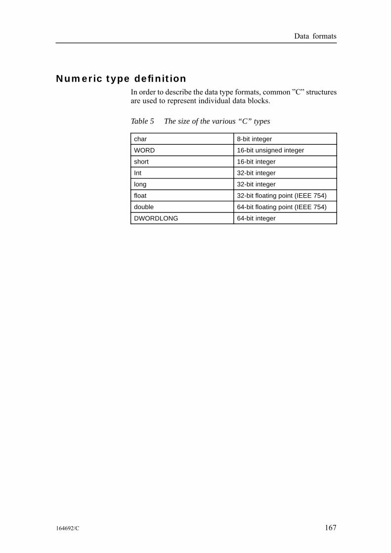
Data formats
Numeric type definitionIn order to describe the data type formats, common ”C” structuresare used to represent individual data blocks.
Table 5 The size of the various “C” types
char 8-bit integer
WORD 16-bit unsigned integer
short 16-bit integer
Int 32-bit integer
long 32-bit integer
float 32-bit floating point (IEEE 754)
double 64-bit floating point (IEEE 754)
DWORDLONG 64-bit integer
164692/C 167
Simrad ER60
Raw dataThe *.raw file may contain one or more of the following datagramtypes:• Configuration• NMEA• Annotation• SampleEvery *.raw file begins with a configuration telegram. A secondconfiguration datagram, within the file, is illegal. The datacontent of the configuration datagram of an already existing filecannot be altered from the echo sounder. NMEA, annotation andsample datagrams constitute the remaining file content. Thesedatagrams are written to the *.raw file in the order that they aregenerated by the sounder.Note that the information following the “//” sign are commentsto that line.
Topics
Data encapsulation on page 169Configuration datagram on page 170NMEA datagrams on page 171Annotation datagrams on page 172Sample datagram on page 173
168 164692/C
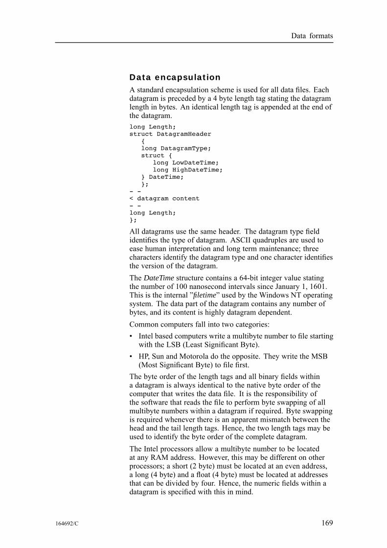
Data formats
Data encapsulationA standard encapsulation scheme is used for all data files. Eachdatagram is preceded by a 4 byte length tag stating the datagramlength in bytes. An identical length tag is appended at the end ofthe datagram.long Length;struct DatagramHeader
{long DatagramType;struct {
long LowDateTime;long HighDateTime;
} DateTime;};
- -< datagram content- -long Length;};
All datagrams use the same header. The datagram type fieldidentifies the type of datagram. ASCII quadruples are used toease human interpretation and long term maintenance; threecharacters identify the datagram type and one character identifiesthe version of the datagram.The DateTime structure contains a 64-bit integer value statingthe number of 100 nanosecond intervals since January 1, 1601.This is the internal ”filetime” used by the Windows NT operatingsystem. The data part of the datagram contains any number ofbytes, and its content is highly datagram dependent.Common computers fall into two categories:• Intel based computers write a multibyte number to file startingwith the LSB (Least Significant Byte).
• HP, Sun and Motorola do the opposite. They write the MSB(Most Significant Byte) to file first.
The byte order of the length tags and all binary fields withina datagram is always identical to the native byte order of thecomputer that writes the data file. It is the responsibility ofthe software that reads the file to perform byte swapping of allmultibyte numbers within a datagram if required. Byte swappingis required whenever there is an apparent mismatch between thehead and the tail length tags. Hence, the two length tags may beused to identify the byte order of the complete datagram.The Intel processors allow a multibyte number to be locatedat any RAM address. However, this may be different on otherprocessors; a short (2 byte) must be located at an even address,a long (4 byte) and a float (4 byte) must be located at addressesthat can be divided by four. Hence, the numeric fields within adatagram is specified with this in mind.
164692/C 169
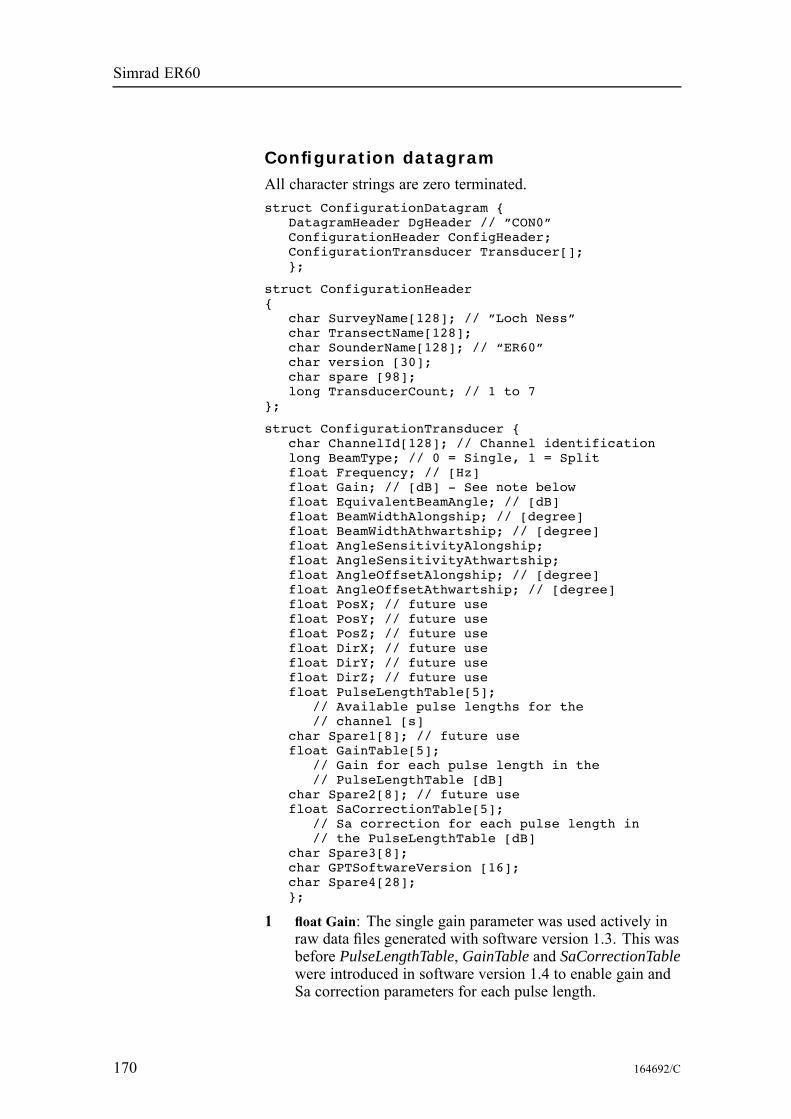
Simrad ER60
Configuration datagramAll character strings are zero terminated.struct ConfigurationDatagram {
DatagramHeader DgHeader // ”CON0”ConfigurationHeader ConfigHeader;ConfigurationTransducer Transducer[];};
struct ConfigurationHeader{
char SurveyName[128]; // ”Loch Ness”char TransectName[128];char SounderName[128]; // “ER60”char version [30];char spare [98];long TransducerCount; // 1 to 7
};
struct ConfigurationTransducer {char ChannelId[128]; // Channel identificationlong BeamType; // 0 = Single, 1 = Splitfloat Frequency; // [Hz]float Gain; // [dB] - See note belowfloat EquivalentBeamAngle; // [dB]float BeamWidthAlongship; // [degree]float BeamWidthAthwartship; // [degree]float AngleSensitivityAlongship;float AngleSensitivityAthwartship;float AngleOffsetAlongship; // [degree]float AngleOffsetAthwartship; // [degree]float PosX; // future usefloat PosY; // future usefloat PosZ; // future usefloat DirX; // future usefloat DirY; // future usefloat DirZ; // future usefloat PulseLengthTable[5];
// Available pulse lengths for the// channel [s]
char Spare1[8]; // future usefloat GainTable[5];
// Gain for each pulse length in the// PulseLengthTable [dB]
char Spare2[8]; // future usefloat SaCorrectionTable[5];
// Sa correction for each pulse length in// the PulseLengthTable [dB]
char Spare3[8];char GPTSoftwareVersion [16];char Spare4[28];};
1 float Gain: The single gain parameter was used actively inraw data files generated with software version 1.3. This wasbefore PulseLengthTable, GainTable and SaCorrectionTablewere introduced in software version 1.4 to enable gain andSa correction parameters for each pulse length.
170 164692/C

Data formats
NMEA datagramsThe NMEA datagrams contain original NMEA 0183 inputsentences.struct TextDatagram{
DatagramHeader DgHeader; // “NME0”char Text[]; // ”$GPGLL,5713.213,N......”
};
The size of the datagram depends on the sentence length.
164692/C 171

Simrad ER60
Annotation datagramsThe annotation datagram contains comment text.struct TextDatagram{
DatagramHeader DgHeader; // “TAG0”char Text[]; // ”Dangerous wreck”
};
The text string is zero terminated. The size of the completedatagram depends on the annotation length (maximum 80characters).
172 164692/C
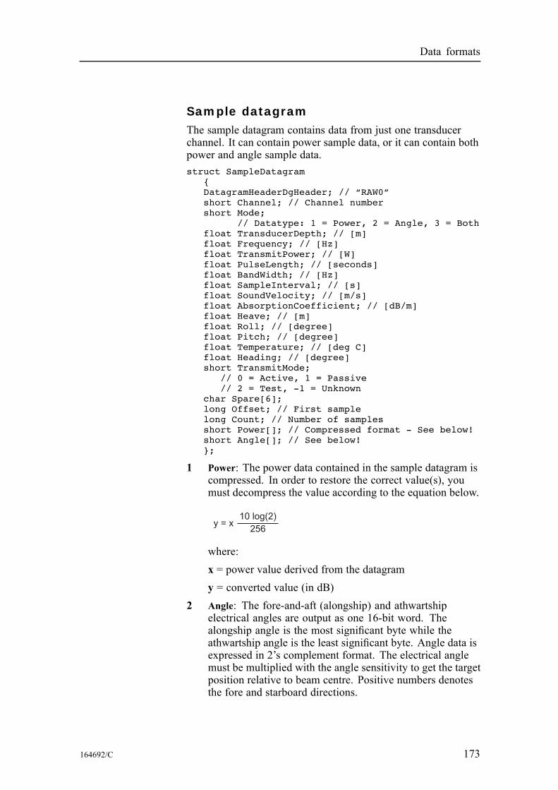
Data formats
Sample datagramThe sample datagram contains data from just one transducerchannel. It can contain power sample data, or it can contain bothpower and angle sample data.struct SampleDatagram
{DatagramHeaderDgHeader; // “RAW0”short Channel; // Channel numbershort Mode;
// Datatype: 1 = Power, 2 = Angle, 3 = Bothfloat TransducerDepth; // [m]float Frequency; // [Hz]float TransmitPower; // [W]float PulseLength; // [seconds]float BandWidth; // [Hz]float SampleInterval; // [s]float SoundVelocity; // [m/s]float AbsorptionCoefficient; // [dB/m]float Heave; // [m]float Roll; // [degree]float Pitch; // [degree]float Temperature; // [deg C]float Heading; // [degree]short TransmitMode;
// 0 = Active, 1 = Passive// 2 = Test, -1 = Unknown
char Spare[6];long Offset; // First samplelong Count; // Number of samplesshort Power[]; // Compressed format - See below!short Angle[]; // See below!};
1 Power: The power data contained in the sample datagram iscompressed. In order to restore the correct value(s), youmust decompress the value according to the equation below.
y = x10 log(2)
256
where:x = power value derived from the datagramy = converted value (in dB)
2 Angle: The fore-and-aft (alongship) and athwartshipelectrical angles are output as one 16-bit word. Thealongship angle is the most significant byte while theathwartship angle is the least significant byte. Angle data isexpressed in 2’s complement format. The electrical anglemust be multiplied with the angle sensitivity to get the targetposition relative to beam centre. Positive numbers denotesthe fore and starboard directions.
164692/C 173
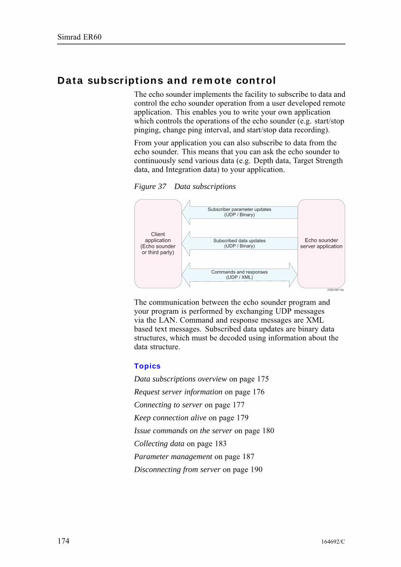
Simrad ER60
Data subscriptions and remote controlThe echo sounder implements the facility to subscribe to data andcontrol the echo sounder operation from a user developed remoteapplication. This enables you to write your own applicationwhich controls the operations of the echo sounder (e.g. start/stoppinging, change ping interval, and start/stop data recording).From your application you can also subscribe to data from theecho sounder. This means that you can ask the echo sounder tocontinuously send various data (e.g. Depth data, Target Strengthdata, and Integration data) to your application.
Figure 37 Data subscriptions
Clientapplication
(Echo sounderor third party)
Subscriber parameter updates(UDP / Binary)
Subscribed data updates(UDP / Binary)
Commands and responses(UDP / XML)
Echo sounderserver application
(CD010017A)
The communication between the echo sounder program andyour program is performed by exchanging UDP messagesvia the LAN. Command and response messages are XMLbased text messages. Subscribed data updates are binary datastructures, which must be decoded using information about thedata structure.
Topics
Data subscriptions overview on page 175Request server information on page 176Connecting to server on page 177Keep connection alive on page 179Issue commands on the server on page 180Collecting data on page 183Parameter management on page 187Disconnecting from server on page 190
174 164692/C
Data formats
Data subscriptions overviewThe following is an overview of the process for data subscriptionand remote control.1 Request server information2 Connect to server3 Keep connection alive4 Issue commands on server
• Subscription of data:a Create data subscriptionsb Handle datac Change data subscriptionsd Destroy data subscriptions
• Parameter management:a Get parameterb Set parameterc Start parameter notificationsd Stop parameter notifications
5 Disconnecting from server
164692/C 175
Simrad ER60
Request server informationBefore you connect to the server running the echo sounderprogram, your client application must obtain information aboutthe server’s IP address and command port number.
RequestServerInfo
Send the following RequestServerInfo message to the specific IPaddress of the server, or broadcast the message to receive serverinformation from all servers on the LAN. The message shouldbe send to the UDP port number found in the Local port fieldon the Server page in the Remoting dialogue box in the serverapplication.struct RequestServerInfo
{char Header[4]; // ”RSI\0”};
ServerInfo2
The server applications will respond to the requesting applicationwith a message containing information about the serverapplication. The content of the ServerInfo2 message is shownbelow.struct ServerInfo2
{char Header[4]; // ”SI2\0”char ApplicationType[64];char ApplicationName[64];
// Name of the current applicationchar ApplicationDescription[128];
// Description of the current applicationlong ApplicationID;
// ID of the current applicationlong CommandPort;
// Port number to send commands tolong Mode;
// If the application is// running against the local data source// or a remote data source
char HostName[64];// IP address of the computer the// application is running on
};
CommandPort
The server UDP port number CommandPort must be used fromnow on to send commands to the server application.
176 164692/C
Data formats
Connecting to serverBefore commands can be sent to the server application, theclient application must identify itself to the server applicationby sending a connect command, ConnectRequest, to the server.This connect command must contain user account and passwordinformation.
ConnectRequest
The contents of the connect message is shown below.struct ConnectRequest
{char Header[4]; // ”CON\0”char ClientInfo[1024];
// e.g. ”Name:Simrad;Password:\0”};
Response
The server application will respond with a Response messagecontaining at least the client id if the connect commandsucceeded, or an error if the connect command failed. Thecontents of the various parts of a response message for asuccessful connect command is shown below.struct Response
{char Header[4]; // ”RES\0”char Request[4]; // ”CON/0”char MsgControl[22]; // ”\0”char MsgResponse[1400];
// Response text containing result of// connection request
};
MsgResponse
The contents of the MsgResponse field consist of ResultCode andParameters.ResultCode: Result of the operation. The following values canbe present:• S_OK: operation was successful• E_ACCESSDENIED: operation failed due to unknown accountor wrong password
• E_FAIL: operation failed due to an unspecified errorParameters: Comma separated list of various name:value pairsthat may be present, only provided if the ConnectRequest issuccessful.• ClientID: identification of the current client, to be used in allfurther communication with the server application
• AccessLevel: general access level for the current client
164692/C 177

Simrad ER60
A successful connection will for example provide a MsgResponsecontaining:ResultCode:S_OK,Parameters:{ClientID:1,AccessLevel:1}\0
Connection failure
In case the connect command fails, the ResponseField will containa ResultInfo field.ResultInfo: Text describing the failure
178 164692/C
Data formats
Keep connection aliveOnce the client application is connected to the server applicationa two-way monitoring of the application and communication”health” must be started. This means that both the client and theserver application must send an ”alive” message, AliveReport,periodically (each second).
AliveReport
The content of the AliveReport message is shown below.struct AliveReport
{char Header[4]; // ”ALI\0”char Info[1024]; // e.g. ”ClientID:1,SeqNo:1\0”
};
The Info field in an AliveReport message from the client to theserver may contain (example):ClientID:1,SeqNo:1\0
SeqNo
The SeqNo part of the Info field shall contain the sequencenumber of the next request message from the client to the server(the sequence number shall start on 1). The server will use this todetect if any messages from the client have been lost, if a loss isdetected, the server will issue a re-transmit request to the client.The AliveReportDef message from the server to the client maycontain (for example):SeqNo:1\0
Similar, the SeqNo part of the Info field shall contain the sequencenumber of the next response message from the server to theclient. The client application can use this to detect if any messagefrom the server is lost, and may then issue a re-transmit requestto the server.
164692/C 179
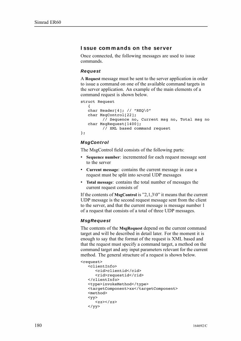
Simrad ER60
Issue commands on the serverOnce connected, the following messages are used to issuecommands.
Request
A Request message must be sent to the server application in orderto issue a command on one of the available command targets inthe server application. An example of the main elements of acommand request is shown below.struct Request
{char Header[4]; // ”REQ\0”char MsgControl[22];
// Sequence no, Current msg no, Total msg nochar MsgRequest[1400];
// XML based command request};
MsgControl
The MsgControl field consists of the following parts:• Sequence number: incremented for each request message sentto the server
• Current message: contains the current message in case arequest must be split into several UDP messages
• Total message: contains the total number of messages thecurrent request consists of
If the contents ofMsgControl is ”2,1,3\0” it means that the currentUDP message is the second request message sent from the clientto the server, and that the current message is message number 1of a request that consists of a total of three UDP messages.
MsgRequest
The contents of theMsgRequest depend on the current commandtarget and will be described in detail later. For the moment it isenough to say that the format of the request is XML based andthat the request must specify a command target, a method on thecommand target and any input parameters relevant for the currentmethod. The general structure of a request is shown below.<request>
<clientInfo><cid>clientid</cid><rid>requestid</rid>
</clientInfo><type>invokeMethod</type><targetComponent>xx</targetComponent><method><yy>
<zz></zz></yy>
180 164692/C
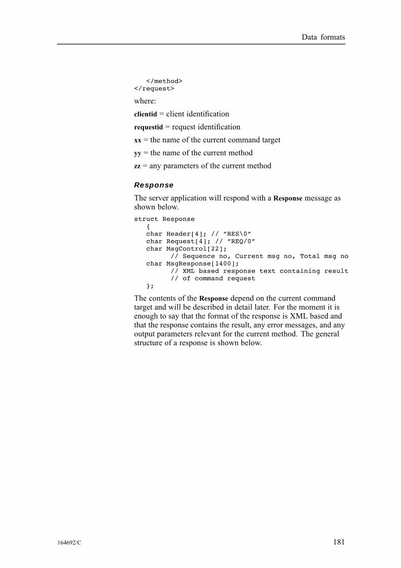
Data formats
</method></request>
where:clientid = client identificationrequestid = request identificationxx = the name of the current command targetyy = the name of the current methodzz = any parameters of the current method
Response
The server application will respond with a Response message asshown below.struct Response
{char Header[4]; // ”RES\0”char Request[4]; // ”REQ/0”char MsgControl[22];
// Sequence no, Current msg no, Total msg nochar MsgResponse[1400];
// XML based response text containing result// of command request
};
The contents of the Response depend on the current commandtarget and will be described in detail later. For the moment it isenough to say that the format of the response is XML based andthat the response contains the result, any error messages, and anyoutput parameters relevant for the current method. The generalstructure of a response is shown below.
164692/C 181
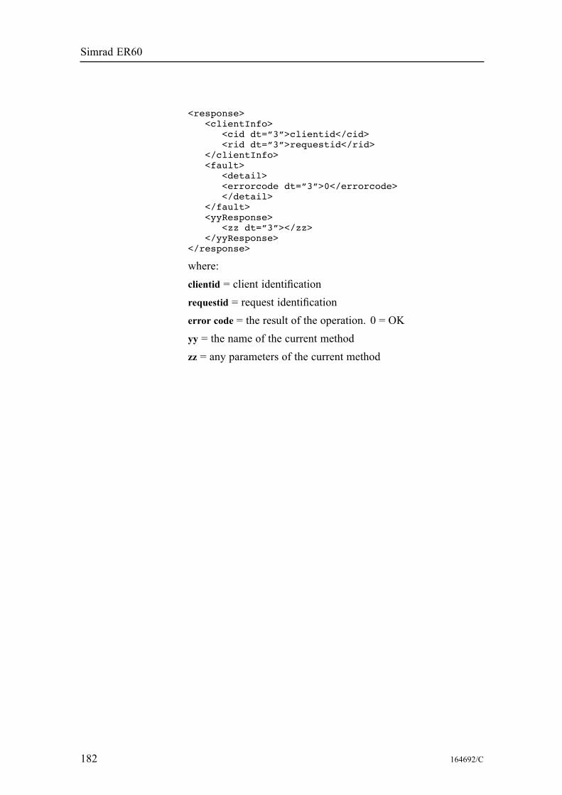
Simrad ER60
<response><clientInfo>
<cid dt=”3”>clientid</cid><rid dt=”3”>requestid</rid>
</clientInfo><fault>
<detail><errorcode dt=”3”>0</errorcode></detail>
</fault><yyResponse>
<zz dt=”3”></zz></yyResponse>
</response>
where:clientid = client identificationrequestid = request identificationerror code = the result of the operation. 0 = OKyy = the name of the current methodzz = any parameters of the current method
182 164692/C
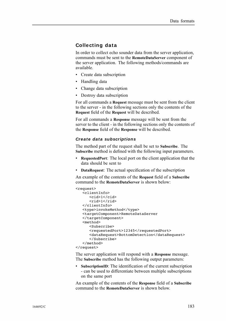
Data formats
Collecting dataIn order to collect echo sounder data from the server application,commands must be sent to the RemoteDataServer component ofthe server application. The following methods/commands areavailable.• Create data subscription• Handling data• Change data subscription• Destroy data subscriptionFor all commands a Request message must be sent from the clientto the server - in the following sections only the contents of theRequest field of the Request will be described.For all commands a Response message will be sent from theserver to the client - in the following sections only the contents ofthe Response field of the Response will be described.
Create data subscriptions
The method part of the request shall be set to Subscribe. TheSubscribe method is defined with the following input parameters.• RequestedPort: The local port on the client application that thedata should be sent to
• DataRequest: The actual specification of the subscriptionAn example of the contents of the Request field of a Subscribecommand to the RemoteDataServer is shown below:<request>
<clientInfo><cid>1</cid><rid>1</rid>
</clientInfo><type>invokeMethod</type><targetComponent>RemoteDataServer</targetComponent><method>
<Subscribe><requestedPort>12345</requestedPort><dataRequest>BottomDetection</dataRequest></Subscribe>
</method></request>
The server application will respond with a Response message.The Subscribe method has the following output parameters:• SubscriptionID: The identification of the current subscription- can be used to differentiate between multiple subscriptionson the same port
An example of the contents of the Response field of a Subscribecommand to the RemoteDataServer is shown below.
164692/C 183
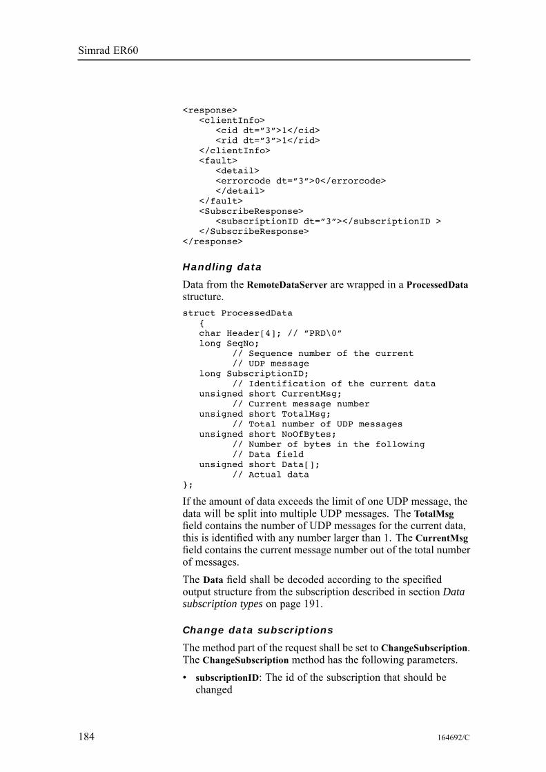
Simrad ER60
<response><clientInfo>
<cid dt=”3”>1</cid><rid dt=”3”>1</rid>
</clientInfo><fault>
<detail><errorcode dt=”3”>0</errorcode></detail>
</fault><SubscribeResponse>
<subscriptionID dt=”3”></subscriptionID ></SubscribeResponse>
</response>
Handling data
Data from the RemoteDataServer are wrapped in a ProcessedDatastructure.struct ProcessedData
{char Header[4]; // ”PRD\0”long SeqNo;
// Sequence number of the current// UDP message
long SubscriptionID;// Identification of the current data
unsigned short CurrentMsg;// Current message number
unsigned short TotalMsg;// Total number of UDP messages
unsigned short NoOfBytes;// Number of bytes in the following// Data field
unsigned short Data[];// Actual data
};
If the amount of data exceeds the limit of one UDP message, thedata will be split into multiple UDP messages. The TotalMsgfield contains the number of UDP messages for the current data,this is identified with any number larger than 1. The CurrentMsgfield contains the current message number out of the total numberof messages.The Data field shall be decoded according to the specifiedoutput structure from the subscription described in section Datasubscription types on page 191.
Change data subscriptions
The method part of the request shall be set to ChangeSubscription.The ChangeSubscription method has the following parameters.• subscriptionID: The id of the subscription that should bechanged
184 164692/C
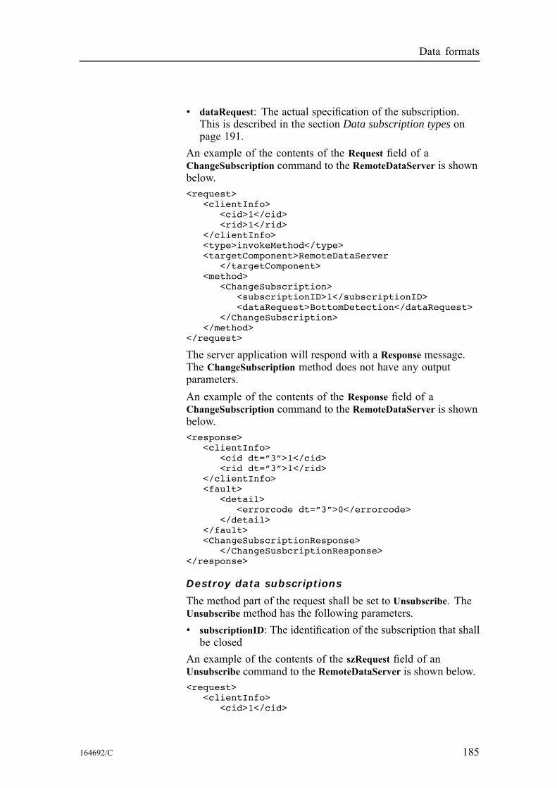
Data formats
• dataRequest: The actual specification of the subscription.This is described in the section Data subscription types onpage 191.
An example of the contents of the Request field of aChangeSubscription command to the RemoteDataServer is shownbelow.<request>
<clientInfo><cid>1</cid><rid>1</rid>
</clientInfo><type>invokeMethod</type><targetComponent>RemoteDataServer
</targetComponent><method>
<ChangeSubscription><subscriptionID>1</subscriptionID><dataRequest>BottomDetection</dataRequest>
</ChangeSubscription></method>
</request>
The server application will respond with a Response message.The ChangeSubscription method does not have any outputparameters.An example of the contents of the Response field of aChangeSubscription command to the RemoteDataServer is shownbelow.<response>
<clientInfo><cid dt=”3”>1</cid><rid dt=”3”>1</rid>
</clientInfo><fault>
<detail><errorcode dt=”3”>0</errorcode>
</detail></fault><ChangeSubscriptionResponse>
</ChangeSusbcriptionResponse></response>
Destroy data subscriptions
The method part of the request shall be set to Unsubscribe. TheUnsubscribe method has the following parameters.• subscriptionID: The identification of the subscription that shallbe closed
An example of the contents of the szRequest field of anUnsubscribe command to the RemoteDataServer is shown below.<request>
<clientInfo><cid>1</cid>
164692/C 185
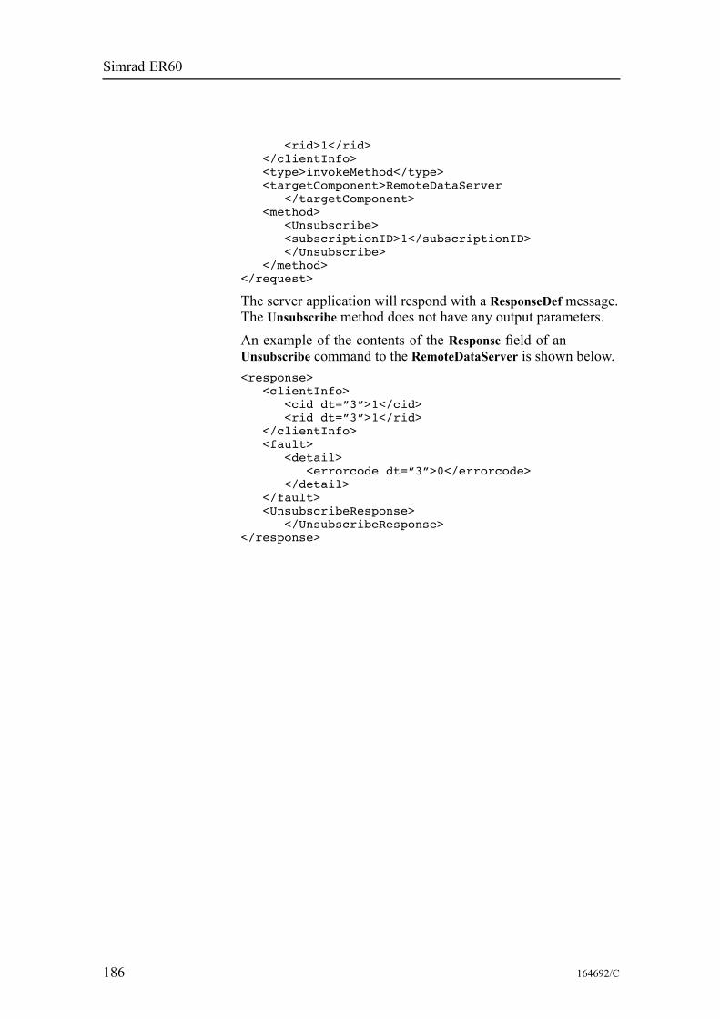
Simrad ER60
<rid>1</rid></clientInfo><type>invokeMethod</type><targetComponent>RemoteDataServer
</targetComponent><method>
<Unsubscribe><subscriptionID>1</subscriptionID></Unsubscribe>
</method></request>
The server application will respond with a ResponseDef message.The Unsubscribe method does not have any output parameters.An example of the contents of the Response field of anUnsubscribe command to the RemoteDataServer is shown below.<response>
<clientInfo><cid dt=”3”>1</cid><rid dt=”3”>1</rid>
</clientInfo><fault>
<detail><errorcode dt=”3”>0</errorcode>
</detail></fault><UnsubscribeResponse>
</UnsubscribeResponse></response>
186 164692/C
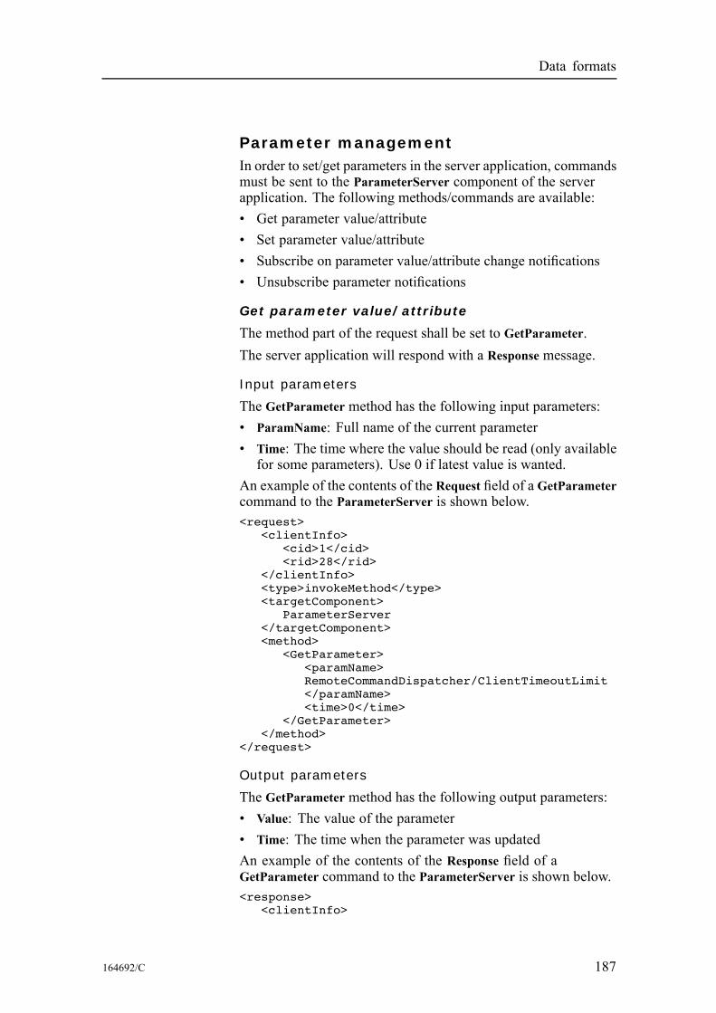
Data formats
Parameter managementIn order to set/get parameters in the server application, commandsmust be sent to the ParameterServer component of the serverapplication. The following methods/commands are available:• Get parameter value/attribute• Set parameter value/attribute• Subscribe on parameter value/attribute change notifications• Unsubscribe parameter notifications
Get parameter value/attribute
The method part of the request shall be set to GetParameter.The server application will respond with a Response message.
Input parameters
The GetParameter method has the following input parameters:• ParamName: Full name of the current parameter• Time: The time where the value should be read (only availablefor some parameters). Use 0 if latest value is wanted.
An example of the contents of the Request field of a GetParametercommand to the ParameterServer is shown below.<request>
<clientInfo><cid>1</cid><rid>28</rid>
</clientInfo><type>invokeMethod</type><targetComponent>
ParameterServer</targetComponent><method>
<GetParameter><paramName>RemoteCommandDispatcher/ClientTimeoutLimit</paramName><time>0</time>
</GetParameter></method>
</request>
Output parameters
The GetParameter method has the following output parameters:• Value: The value of the parameter• Time: The time when the parameter was updatedAn example of the contents of the Response field of aGetParameter command to the ParameterServer is shown below.<response>
<clientInfo>
164692/C 187
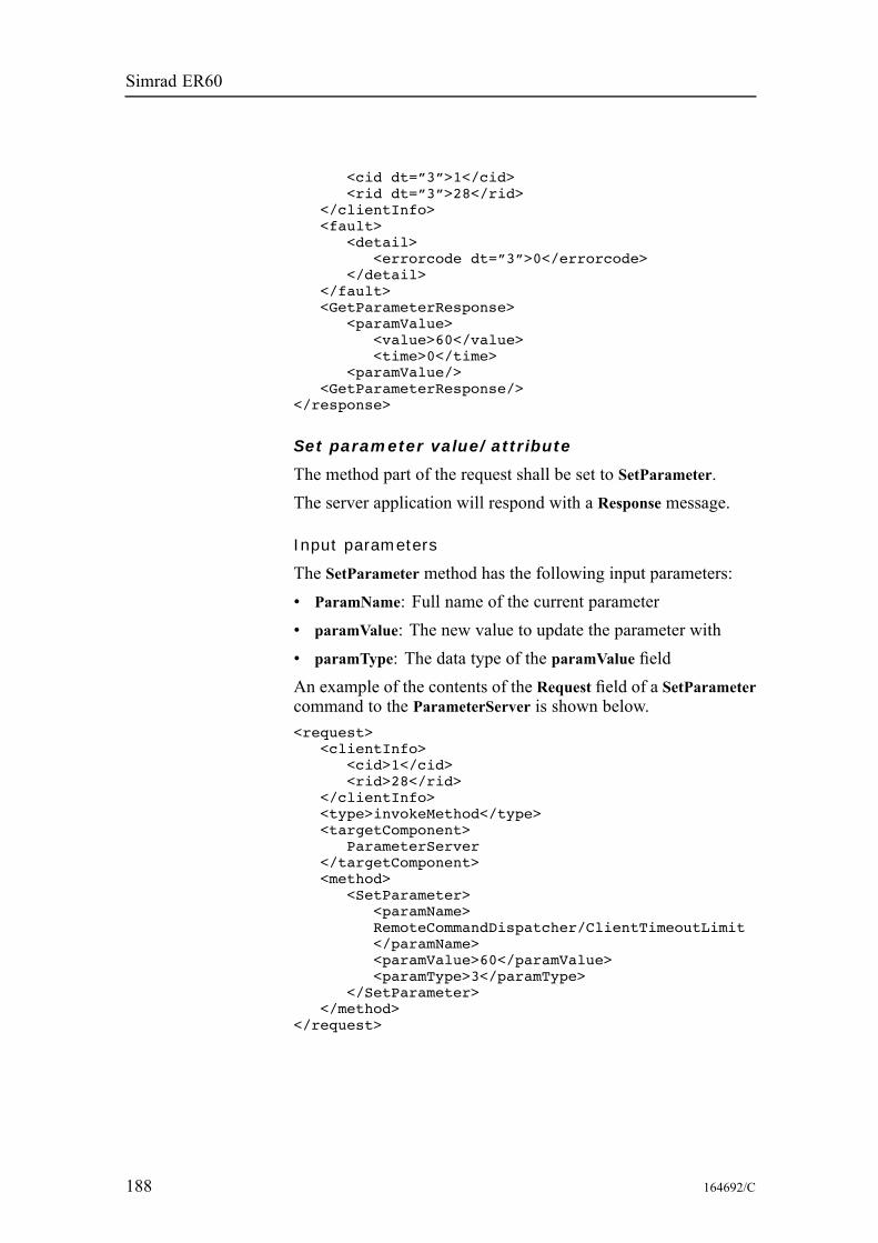
Simrad ER60
<cid dt=”3”>1</cid><rid dt=”3”>28</rid>
</clientInfo><fault>
<detail><errorcode dt=”3”>0</errorcode>
</detail></fault><GetParameterResponse>
<paramValue><value>60</value><time>0</time>
<paramValue/><GetParameterResponse/>
</response>
Set parameter value/attribute
The method part of the request shall be set to SetParameter.The server application will respond with a Response message.
Input parameters
The SetParameter method has the following input parameters:• ParamName: Full name of the current parameter• paramValue: The new value to update the parameter with• paramType: The data type of the paramValue fieldAn example of the contents of the Request field of a SetParametercommand to the ParameterServer is shown below.<request>
<clientInfo><cid>1</cid><rid>28</rid>
</clientInfo><type>invokeMethod</type><targetComponent>
ParameterServer</targetComponent><method>
<SetParameter><paramName>RemoteCommandDispatcher/ClientTimeoutLimit</paramName><paramValue>60</paramValue><paramType>3</paramType>
</SetParameter></method>
</request>
188 164692/C
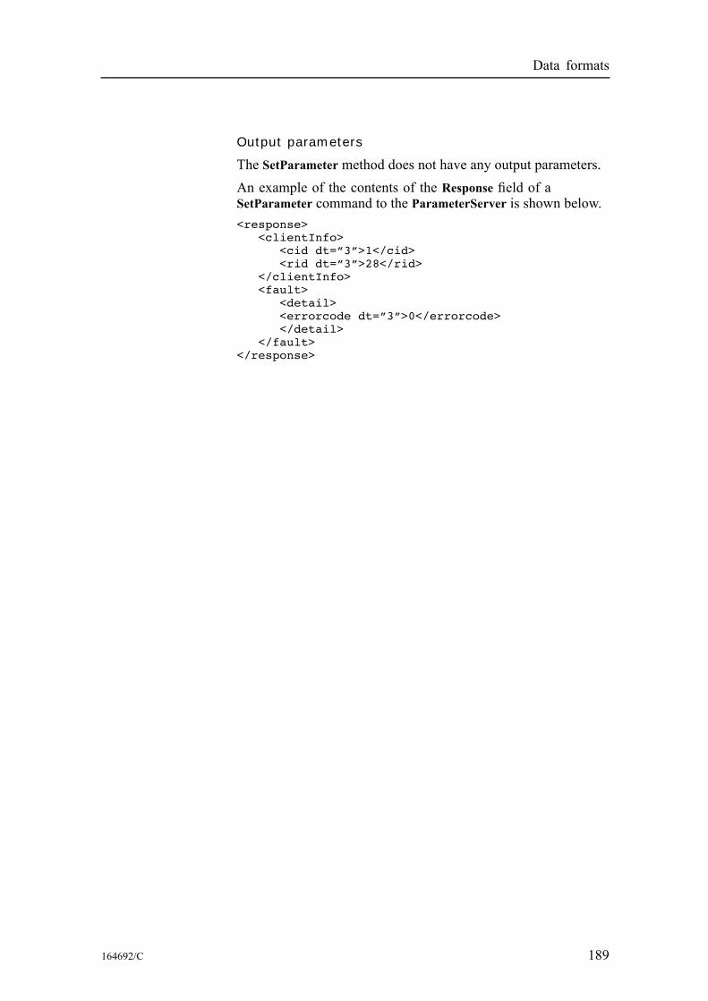
Data formats
Output parameters
The SetParameter method does not have any output parameters.An example of the contents of the Response field of aSetParameter command to the ParameterServer is shown below.<response>
<clientInfo><cid dt=”3”>1</cid><rid dt=”3”>28</rid>
</clientInfo><fault>
<detail><errorcode dt=”3”>0</errorcode></detail>
</fault></response>
164692/C 189

Simrad ER60
Disconnecting from serverThe client application shall send a DisconnectRequestDef messageto the server application when the client is finished with itsoperation against the server.The parameters are:• Header: DIS\0• szClientInfo: Name:Simrad;Password:\0
190 164692/C
Data formats
Data subscription typesThis section describes the available data subscriptions in theecho sounder.All data subscriptions require the ChannelID (channel identifier)for the frequency channel from which the subscription data isrequested. A comma separated list of available identifiers canbe obtained using the ParameterServer component to get theparameter TransceiverMgr Channels.The data output will always start with a 64-bit integer time value,which identifies the number of 100 nanoseconds intervals that haselapsed since January 1, 1601. If a parameter is skipped in thesubscription input string it will be replaced by the default value.The decoding of the subscription will be case insensitive. In theoutput data to be received by external devices, the informationabout the current structure length is given. From this information,the number of elements in an array may be calculated.
Topics
Bottom detection on page 192Target strength (TS) detection on page 193Sample data on page 195Echogram on page 197Targets echogram on page 198Integration on page 199Targets integration on page 200
164692/C 191
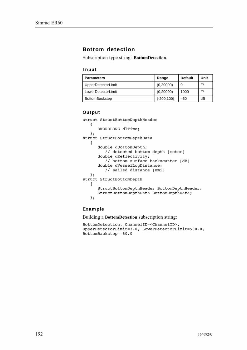
Simrad ER60
Bottom detectionSubscription type string: BottomDetection.
Input
Parameters Range Default Unit
UpperDetectorLimit (0,20000) 0 m
LowerDetectorLimit (0,20000) 1000 m
BottomBackstep (-200,100) –50 dB
Output
struct StructBottomDepthHeader{
DWORDLONG dlTime;};
struct StructBottomDepthData{
double dBottomDepth;// detected bottom depth [meter]
double dReflectivity;// bottom surface backscatter [dB]
double dVesselLogDistance;// sailed distance [nmi]
};struct StructBottomDepth
{StructBottomDepthHeader BottomDepthHeader;StructBottomDepthData BottomDepthData;
};
Example
Building a BottomDetection subscription string:BottomDetection, ChannelID=<ChannelID>,UpperDetectorLimit=3.0, LowerDetectorLimit=500.0,BottomBackstep=-60.0
192 164692/C
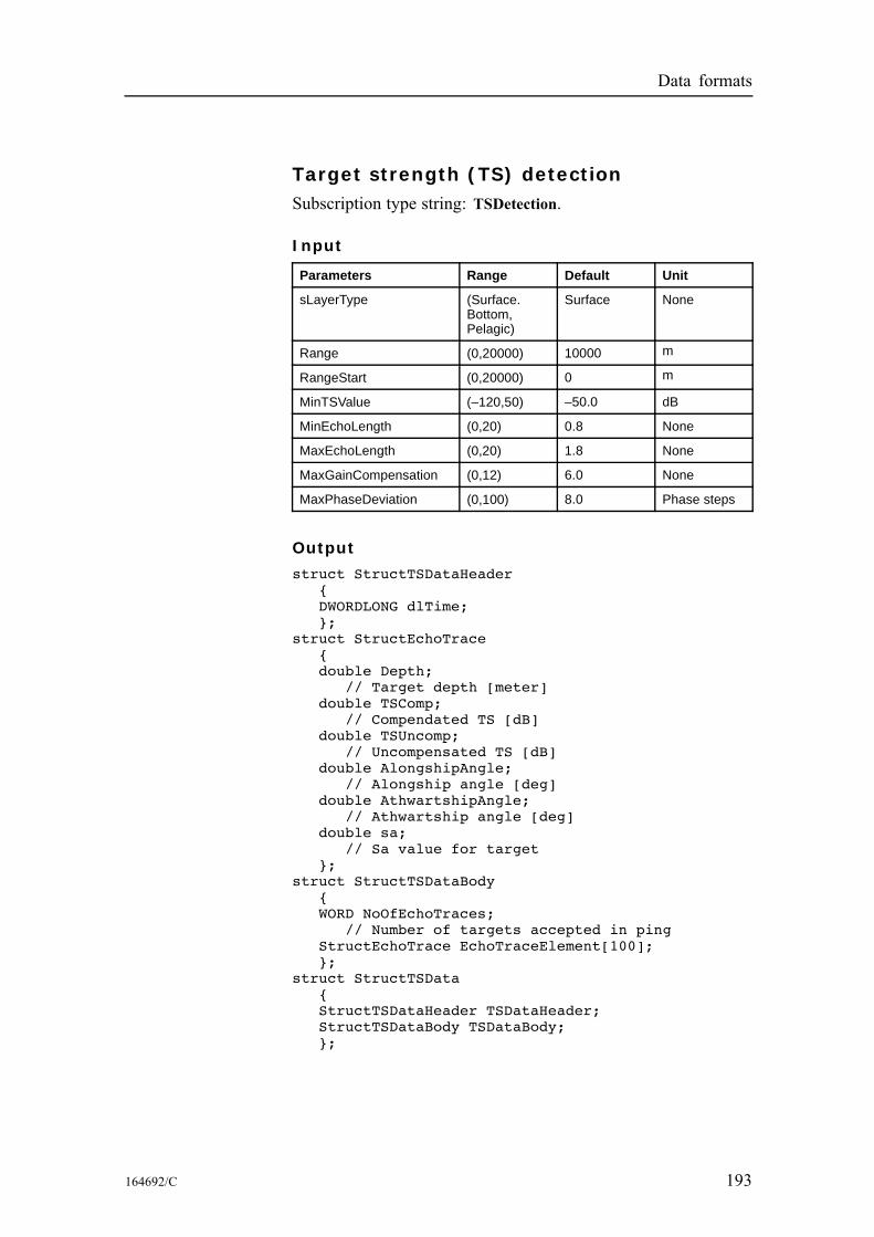
Data formats
Target strength (TS) detectionSubscription type string: TSDetection.
Input
Parameters Range Default Unit
sLayerType (Surface.Bottom,Pelagic)
Surface None
Range (0,20000) 10000 m
RangeStart (0,20000) 0 m
MinTSValue (–120,50) –50.0 dB
MinEchoLength (0,20) 0.8 None
MaxEchoLength (0,20) 1.8 None
MaxGainCompensation (0,12) 6.0 None
MaxPhaseDeviation (0,100) 8.0 Phase steps
Output
struct StructTSDataHeader{DWORDLONG dlTime;};
struct StructEchoTrace{double Depth;
// Target depth [meter]double TSComp;
// Compendated TS [dB]double TSUncomp;
// Uncompensated TS [dB]double AlongshipAngle;
// Alongship angle [deg]double AthwartshipAngle;
// Athwartship angle [deg]double sa;
// Sa value for target};
struct StructTSDataBody{WORD NoOfEchoTraces;
// Number of targets accepted in pingStructEchoTrace EchoTraceElement[100];};
struct StructTSData{StructTSDataHeader TSDataHeader;StructTSDataBody TSDataBody;};
164692/C 193

Simrad ER60
Example
Building a TSDetection subscription string:TSDetection, ChannelID=<ChannelID>,LayerType=Surface, Range=200,RangeStart=3, MinTSValue=-55,MinEcholength=0.7, MaxEcholength=2.0,MaxGainCompensation=6.0, MaxPhasedeviation=7.0
194 164692/C
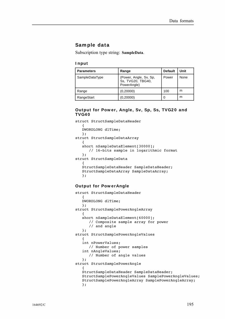
Data formats
Sample dataSubscription type string: SampleData.
Input
Parameters Range Default Unit
SampleDataType (Power, Angle, Sv, Sp,Ss, TVG20, TBG40,PowerAngle)
Power None
Range (0,20000) 100 m
RangeStart (0,20000) 0 m
Output for Power, Angle, Sv, Sp, Ss, TVG20 andTVG40
struct StructSampleDataHeader{DWORDLONG dlTime;};
struct StructSampleDataArray{short nSampleDataElement[30000];
// 16-bits sample in logarithmic format};
struct StructSampleData{StructSampleDataHeader SampleDataHeader;StructSampleDataArray SampleDataArray;};
Output for PowerAngle
struct StructSampleDataHeader{DWORDLONG dlTime;};
struct StructSamplePowerAngleArray{short nSampleDataElement[60000];
// Composite sample array for power// and angle
};struct StructSamplePowerAngleValues
{int nPowerValues;
// Number of power samplesint nAngleValues;
// Number of angle values};
struct StructSamplePowerAngle{StructSampleDataHeader SampleDataHeader;StructSamplePowerAngleValues SamplePowerAngleValues;StructSamplePowerAngleArray SamplePowerAngleArray;};
164692/C 195

Simrad ER60
Example
Building an SampleData subscription string:SampleData,ChannelID=<ChannelID>,SampleDataType=Power, Range=100,RangeStart=10
196 164692/C
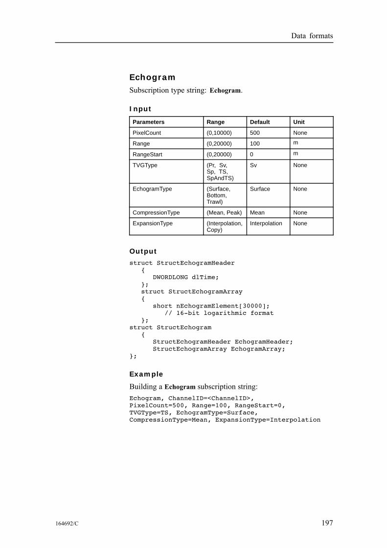
Data formats
EchogramSubscription type string: Echogram.
Input
Parameters Range Default Unit
PixelCount (0,10000) 500 None
Range (0,20000) 100 m
RangeStart (0,20000) 0 m
TVGType (Pr, Sv,Sp, TS,SpAndTS)
Sv None
EchogramType (Surface,Bottom,Trawl)
Surface None
CompressionType (Mean, Peak) Mean None
ExpansionType (Interpolation,Copy)
Interpolation None
Output
struct StructEchogramHeader{
DWORDLONG dlTime;};struct StructEchogramArray{
short nEchogramElement[30000];// 16-bit logarithmic format
};struct StructEchogram
{StructEchogramHeader EchogramHeader;StructEchogramArray EchogramArray;
};
Example
Building a Echogram subscription string:Echogram, ChannelID=<ChannelID>,PixelCount=500, Range=100, RangeStart=0,TVGType=TS, EchogramType=Surface,CompressionType=Mean, ExpansionType=Interpolation
164692/C 197
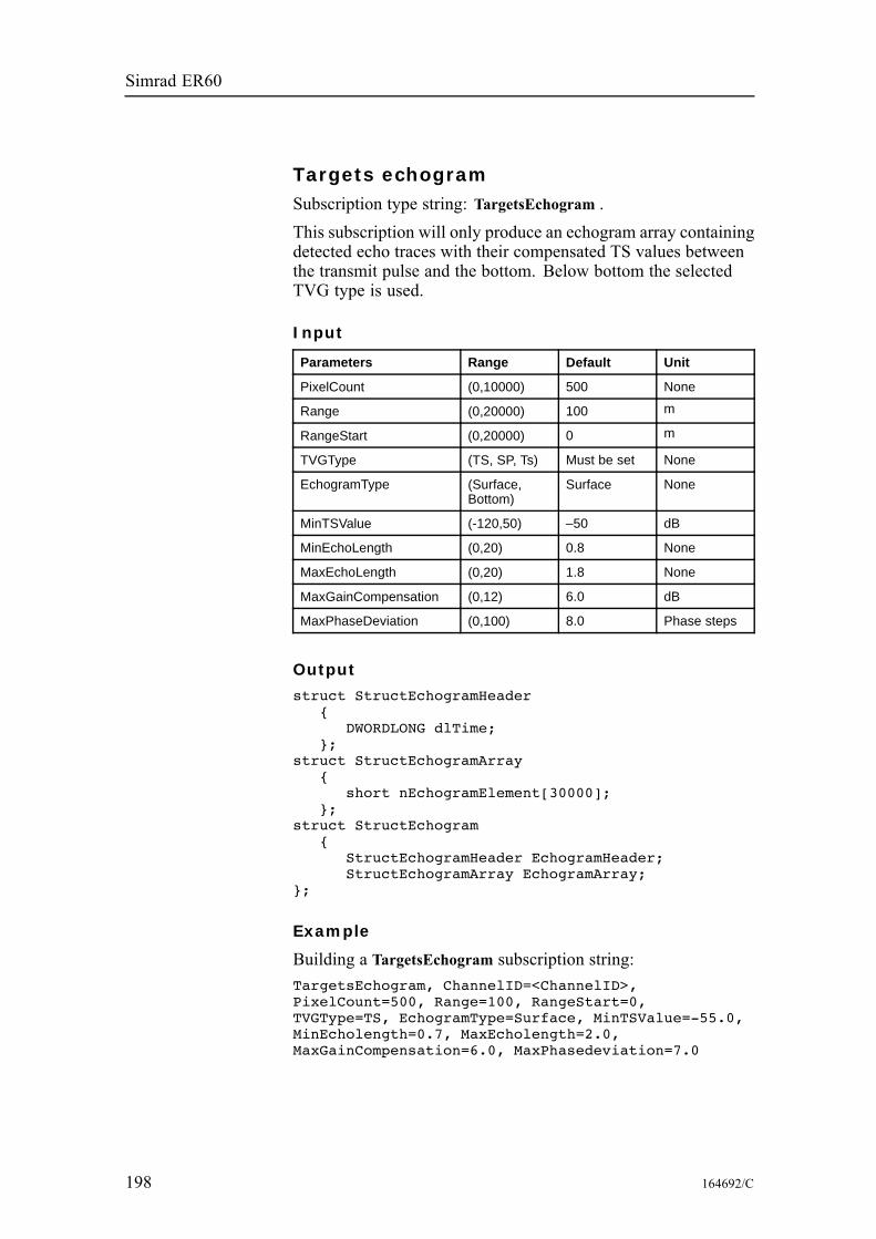
Simrad ER60
Targets echogramSubscription type string: TargetsEchogram .This subscription will only produce an echogram array containingdetected echo traces with their compensated TS values betweenthe transmit pulse and the bottom. Below bottom the selectedTVG type is used.
Input
Parameters Range Default Unit
PixelCount (0,10000) 500 None
Range (0,20000) 100 m
RangeStart (0,20000) 0 m
TVGType (TS, SP, Ts) Must be set None
EchogramType (Surface,Bottom)
Surface None
MinTSValue (-120,50) –50 dB
MinEchoLength (0,20) 0.8 None
MaxEchoLength (0,20) 1.8 None
MaxGainCompensation (0,12) 6.0 dB
MaxPhaseDeviation (0,100) 8.0 Phase steps
Output
struct StructEchogramHeader{
DWORDLONG dlTime;};
struct StructEchogramArray{
short nEchogramElement[30000];};
struct StructEchogram{
StructEchogramHeader EchogramHeader;StructEchogramArray EchogramArray;
};
Example
Building a TargetsEchogram subscription string:TargetsEchogram, ChannelID=<ChannelID>,PixelCount=500, Range=100, RangeStart=0,TVGType=TS, EchogramType=Surface, MinTSValue=-55.0,MinEcholength=0.7, MaxEcholength=2.0,MaxGainCompensation=6.0, MaxPhasedeviation=7.0
198 164692/C
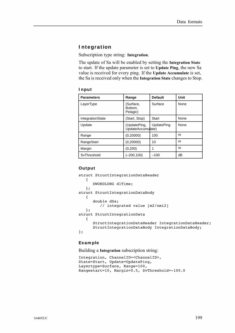
Data formats
IntegrationSubscription type string: Integration.The update of Sa will be enabled by setting the Integration Stateto start. If the update parameter is set to Update Ping, the new Savalue is received for every ping. If the Update Accumulate is set,the Sa is received only when the Integration State changes to Stop.
Input
Parameters Range Default Unit
LayerType (Surface,Bottom,Pelagic)
Surface None
IntegrationState (Start, Stop) Start None
Update (UpdatePing,UpdateAccumulate)
UpdatePing None
Range (0,20000) 100 m
RangeStart (0,20000) 10 m
Margin (0,200) 1 m
SvThreshold (–200,100) –100 dB
Output
struct StructIntegrationDataHeader{
DWORDLONG dlTime;};
struct StructIntegrationDataBody{
double dSa;// integrated value [m2/nmi2]
};struct StructIntegrationData
{StructIntegrationDataHeader IntegrationDataHeader;StructIntegrationDataBody IntegrationDataBody;
};
Example
Building a Integration subscription string:Integration, ChannelID=<ChannelID>,State=Start, Update=UpdatePing,Layertype=Surface, Range=100,Rangestart=10, Margin=0.5, SvThreshold=-100.0
164692/C 199
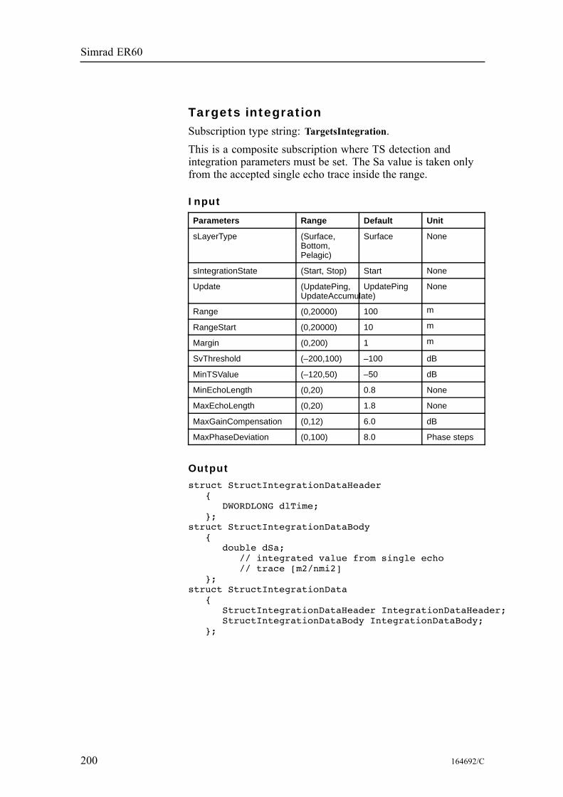
Simrad ER60
Targets integrationSubscription type string: TargetsIntegration.This is a composite subscription where TS detection andintegration parameters must be set. The Sa value is taken onlyfrom the accepted single echo trace inside the range.
Input
Parameters Range Default Unit
sLayerType (Surface,Bottom,Pelagic)
Surface None
sIntegrationState (Start, Stop) Start None
Update (UpdatePing,UpdateAccumulate)
UpdatePing None
Range (0,20000) 100 m
RangeStart (0,20000) 10 m
Margin (0,200) 1 m
SvThreshold (–200,100) –100 dB
MinTSValue (–120,50) –50 dB
MinEchoLength (0,20) 0.8 None
MaxEchoLength (0,20) 1.8 None
MaxGainCompensation (0,12) 6.0 dB
MaxPhaseDeviation (0,100) 8.0 Phase steps
Output
struct StructIntegrationDataHeader{
DWORDLONG dlTime;};
struct StructIntegrationDataBody{
double dSa;// integrated value from single echo// trace [m2/nmi2]
};struct StructIntegrationData
{StructIntegrationDataHeader IntegrationDataHeader;StructIntegrationDataBody IntegrationDataBody;
};
200 164692/C

Data formats
Example
Building a TargetsIntegration subscription string:TargetsIntegration, ChannelID=<ChannelID>,State=Start, Layertype=Surface, Range=100,Rangestart=10, Margin=0.5, SvThreshold=-100.0,MinTSValue=-55.0, MinEcholength=0.7,MaxEcholength=2.0, MaxGainCompensation=6.0,MaxPhasedeviation=7.0
164692/C 201
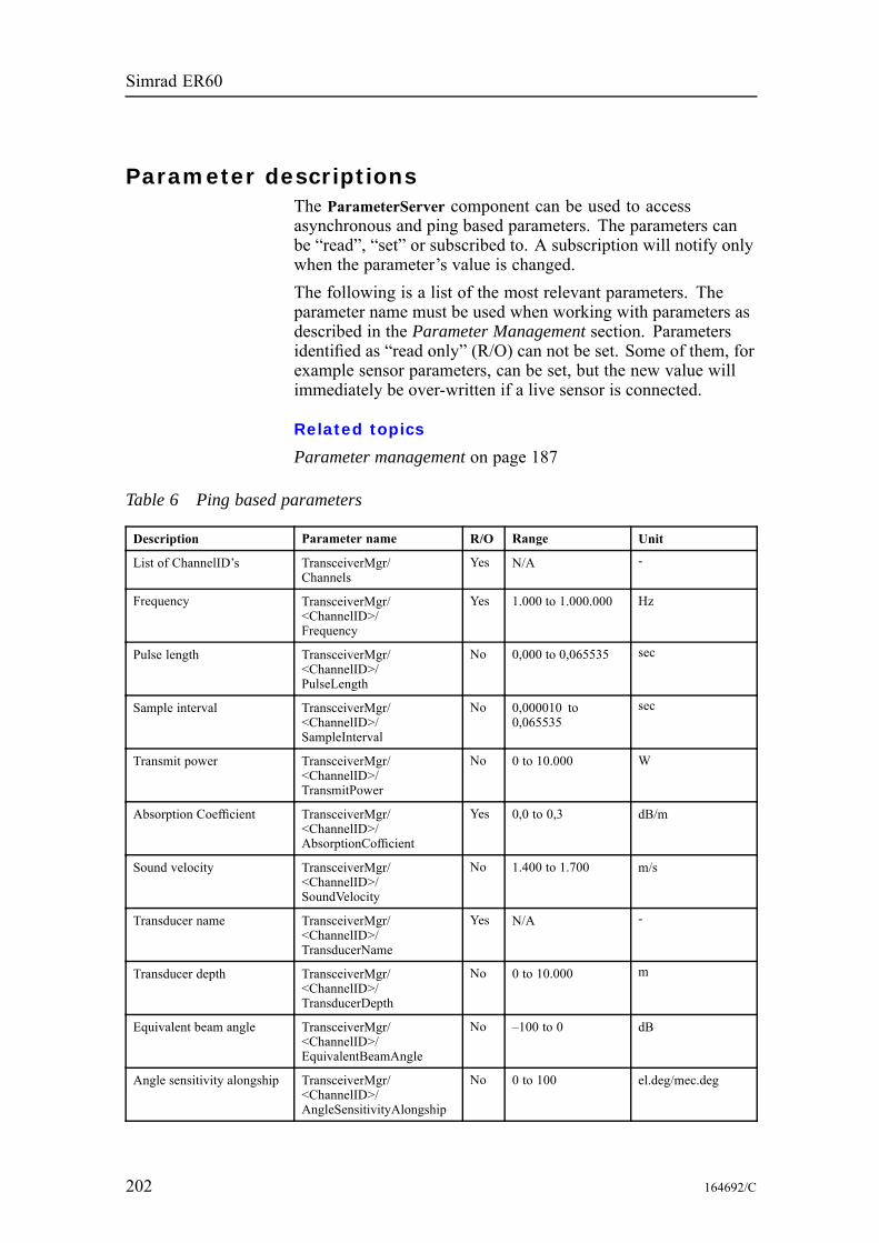
Simrad ER60
Parameter descriptionsThe ParameterServer component can be used to accessasynchronous and ping based parameters. The parameters canbe “read”, “set” or subscribed to. A subscription will notify onlywhen the parameter’s value is changed.The following is a list of the most relevant parameters. Theparameter name must be used when working with parameters asdescribed in the Parameter Management section. Parametersidentified as “read only” (R/O) can not be set. Some of them, forexample sensor parameters, can be set, but the new value willimmediately be over-written if a live sensor is connected.
Related topics
Parameter management on page 187
Table 6 Ping based parameters
Description Parameter name R/O Range Unit
List of ChannelID’s TransceiverMgr/Channels
Yes N/A -
Frequency TransceiverMgr/<ChannelID>/Frequency
Yes 1.000 to 1.000.000 Hz
Pulse length TransceiverMgr/<ChannelID>/PulseLength
No 0,000 to 0,065535 sec
Sample interval TransceiverMgr/<ChannelID>/SampleInterval
No 0,000010 to0,065535
sec
Transmit power TransceiverMgr/<ChannelID>/TransmitPower
No 0 to 10.000 W
Absorption Coefficient TransceiverMgr/<ChannelID>/AbsorptionCofficient
Yes 0,0 to 0,3 dB/m
Sound velocity TransceiverMgr/<ChannelID>/SoundVelocity
No 1.400 to 1.700 m/s
Transducer name TransceiverMgr/<ChannelID>/TransducerName
Yes N/A -
Transducer depth TransceiverMgr/<ChannelID>/TransducerDepth
No 0 to 10.000 m
Equivalent beam angle TransceiverMgr/<ChannelID>/EquivalentBeamAngle
No –100 to 0 dB
Angle sensitivity alongship TransceiverMgr/<ChannelID>/AngleSensitivityAlongship
No 0 to 100 el.deg/mec.deg
202 164692/C
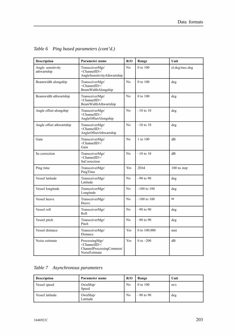
Data formats
Table 6 Ping based parameters (cont’d.)
Description Parameter name R/O Range Unit
Angle sensitivityathwartship
TransceiverMgr/<ChannelID>/AngleSensitivityAthwartship
No 0 to 100 el.deg/mec.deg
Beamwidth alongship TransceiverMgr/<ChannelID>/BeamWidthAlongship
No 0 to 100 deg
Beamwidth athwartship TransceiverMgr/<ChannelID>/BeamWidthAthwartship
No 0 to 100 deg
Angle offset alongship TransceiverMgr/<ChannelID>/AngleOffsetAlongship
No –10 to 10 deg
Angle offset athwartship TransceiverMgr/<ChannelID>/AngleOffsetAthwartship
No –10 to 10 deg
Gain TransceiverMgr/<ChannelID>/Gain
No 1 to 100 dB
Sa correction TransceiverMgr/<ChannelID>/SaCorrection
No –10 to 10 dB
Ping time TransceiverMgr/PingTime
Yes 2E64 100 ns step
Vessel latitude TransceiverMgr/Latitude
No –90 to 90 deg
Vessel longitude TransceiverMgr/Longitude
No –180 to 180 deg
Vessel heave TransceiverMgr/Heave
No –100 to 100 m
Vessel roll TransceiverMgr/Roll
No –90 to 90 deg
Vessel pitch TransceiverMgr/Pitch
No –90 to 90 deg
Vessel distance TransceiverMgr/Distance
Yes 0 to 100.000 nmi
Noise estimate ProcessingMgr/<ChannelID>/ChannelProcessingCommon/NoiseEstimate
Yes 0 to –200 dB
Table 7 Asynchronous parameters
Description Parameter name R/O Range Unit
Vessel speed OwnShip/Speed
No 0 to 100 m/s
Vessel latitude OwnShip/Latitude
No –90 to 90 deg
164692/C 203
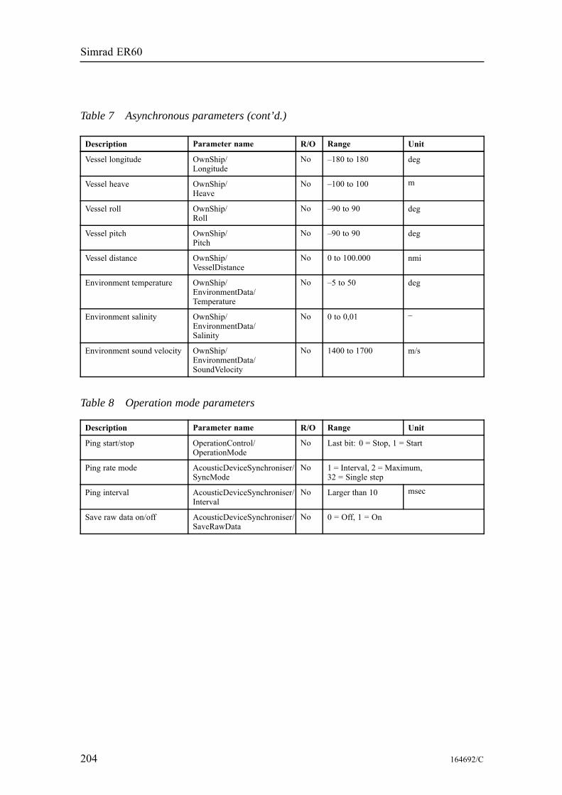
Simrad ER60
Table 7 Asynchronous parameters (cont’d.)
Description Parameter name R/O Range Unit
Vessel longitude OwnShip/Longitude
No –180 to 180 deg
Vessel heave OwnShip/Heave
No –100 to 100 m
Vessel roll OwnShip/Roll
No –90 to 90 deg
Vessel pitch OwnShip/Pitch
No –90 to 90 deg
Vessel distance OwnShip/VesselDistance
No 0 to 100.000 nmi
Environment temperature OwnShip/EnvironmentData/Temperature
No –5 to 50 deg
Environment salinity OwnShip/EnvironmentData/Salinity
No 0 to 0,01 –
Environment sound velocity OwnShip/EnvironmentData/SoundVelocity
No 1400 to 1700 m/s
Table 8 Operation mode parameters
Description Parameter name R/O Range Unit
Ping start/stop OperationControl/OperationMode
No Last bit: 0 = Stop, 1 = Start
Ping rate mode AcousticDeviceSynchroniser/SyncMode
No 1 = Interval, 2 = Maximum,32 = Single step
Ping interval AcousticDeviceSynchroniser/Interval
No Larger than 10 msec
Save raw data on/off AcousticDeviceSynchroniser/SaveRawData
No 0 = Off, 1 = On
204 164692/C

Data formats
NMEA telegram specificationsThe NMEA telegrams supported by the Simrad ER60 Scientificecho sounder are briefly described in this section. For detailedinformation about the telegrams, refer to the official NMEAdocumentation.
Topics
GGA Global positioning system fix data on page 205GLL Geographical position latitude/longitude on page 206HDG Heading, deviation and variation on page 206HDM Heading, magnetic on page 206HDT Heading, true on page 207RMC Recommended minimum specific GNSS data on page 207VHW Water speed and heading on page 207VLW Dual ground/water distance on page 208VTG Course over ground and Ground speed on page 208
GGA Global positioning system fix dataThis telegram contains time, position and fix related data from aglobal positioning system (GPS).$--GGA,hhmmss.ss,llll.ll,a,yyyyy.yy,a,x,zz,d.d,a.a,M,g.g,M,r.r,cccc*hh<CR><LF>
• GGA = telegram identifier• hhmmss.ss = coordinated universal time (UTC) of position• llll.ll,a = latitude nort/south, position in degrees, minutes andhundredths. Characters N (North) or S (South) identifies thebearing.
• yyyyy.yy,a = longitude east/west, position in degrees, minutesand hundredths. Characters W (West) or E (East) identifiesthe bearing.
• x = GPS quality indicator (refer to the NMEA standard forfurther details)
• zz = number of satellites in use, 00 to 12, may be differentfrom the number in view
• d.d = horizontal dilution of precision• a.a,M = altitude related to mean sea level (geoid) in meters• g.g,M = geoidal separation in meters• r.r = age of differential GPS data• cccc = differential reference station identification, 0000 to1023
164692/C 205
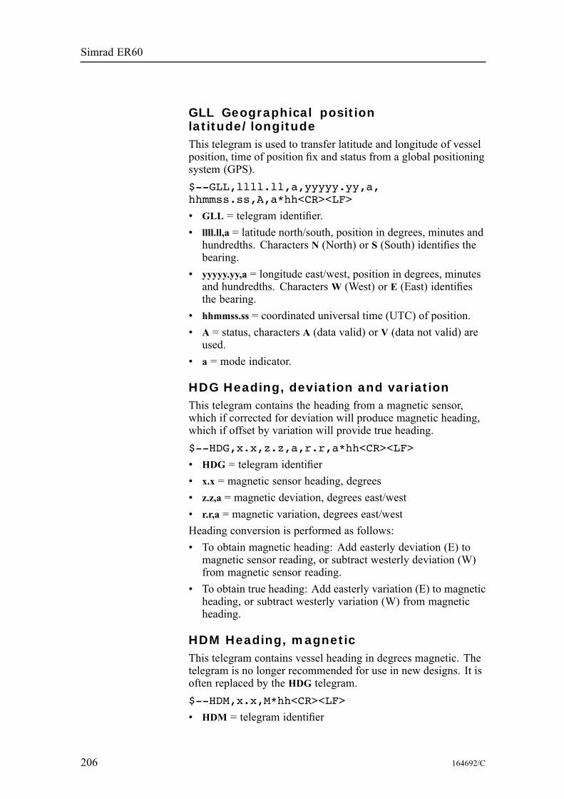
Simrad ER60
GLL Geographical positionlatitude/longitudeThis telegram is used to transfer latitude and longitude of vesselposition, time of position fix and status from a global positioningsystem (GPS).$--GLL,llll.ll,a,yyyyy.yy,a,hhmmss.ss,A,a*hh<CR><LF>
• GLL = telegram identifier.• llll.ll,a = latitude north/south, position in degrees, minutes andhundredths. Characters N (North) or S (South) identifies thebearing.
• yyyyy.yy,a = longitude east/west, position in degrees, minutesand hundredths. Characters W (West) or E (East) identifiesthe bearing.
• hhmmss.ss = coordinated universal time (UTC) of position.• A = status, characters A (data valid) or V (data not valid) areused.
• a = mode indicator.
HDG Heading, deviation and variationThis telegram contains the heading from a magnetic sensor,which if corrected for deviation will produce magnetic heading,which if offset by variation will provide true heading.$--HDG,x.x,z.z,a,r.r,a*hh<CR><LF>
• HDG = telegram identifier• x.x = magnetic sensor heading, degrees• z.z,a = magnetic deviation, degrees east/west• r.r,a = magnetic variation, degrees east/westHeading conversion is performed as follows:• To obtain magnetic heading: Add easterly deviation (E) tomagnetic sensor reading, or subtract westerly deviation (W)from magnetic sensor reading.
• To obtain true heading: Add easterly variation (E) to magneticheading, or subtract westerly variation (W) from magneticheading.
HDM Heading, magneticThis telegram contains vessel heading in degrees magnetic. Thetelegram is no longer recommended for use in new designs. It isoften replaced by the HDG telegram.$--HDM,x.x,M*hh<CR><LF>
• HDM = telegram identifier
206 164692/C

Data formats
• x.x = heading in degrees, magnetic
HDT Heading, trueThis telegram is used to transfer heading information from a gyro.$--HDT,x.x,T*hh<CR><LF>
• HDT = telegram identifier• x.x,T = heading, degrees true
RMC Recommended minimum specificGNSS dataThis telegram contains time, date, position, course and speed dataprovided by a global navigation satellite system (GNSS) receiver.$--RMC,hhmmss.ss,A,llll.ll,a,yyyyy.yy,a,x.x,z.z,ddmmyy,r.r,a,a*hh<CR><LF>
• RMC = telegram identifier• hhmmss.ss = coordinated universal time (UTC) of position fix• A = status, characters A (data valid) or V (Navigation receiverwarning) are used.
• llll.ll,a = latitude nort/south. Characters N (North) or S (South)identifies the bearing.
• yyyyy.yy.a = longitude east/west. Characters E (East) or W(West) identifies the bearing.
• x.x = speed over ground, knots• z.z = course over ground, degrees true• ddmmyy = date• r.r,a = magnetic variation, degrees east/west. Characters E(East) orW (West) identifies the bearing.
• a = mode indicator
VHW Water speed and headingThis telegram contains the compass heading to which the vesselpoints and the speed of the vessel relative to the water.$--VHW,x.x,T,x.x,M,x.x,N,x.x,K*hh<CR><LF>
• VHW = telegram identifier• x.x,T = heading, degrees true• x.x,M = heading, degrees magnetic• x.x,N = speed relative to water, knots, resolution 0.1• x.x,K = speed relative to water, km/hr, resolution 0.1
164692/C 207

Simrad ER60
VLW Dual ground/water distanceThis telegram contains the distance travelled relative to the waterand over the ground.$--VLW,x.x,N,y.y,N,z.z,N,g.g,N*hh<CR><LF>
• VLW = telegram identifier• x.x,N = total cumulative water distance, nautical miles.• y.y,N = water distance since reset, nautical miles.• z.z,N = total cumulative ground distance, nautical miles.• g.g,N = ground distance since reset, nautical miles.
VTG Course over ground and Ground speedThis telegram contains the actual course and speed relative tothe ground.$--VTG,x.x,T,y.y,M,z.z,N,g.g,K,a*hh<CR><LF>
• VTG = telegram identifier• x.x,T = course over ground, degrees true• y.y,M = course over ground, degrees magnetic• z.z,N = speed over ground, knots, resolution 0.1• g.g,K = speed over ground, km/hr, resolution 0.1• a = mode indicator
208 164692/C
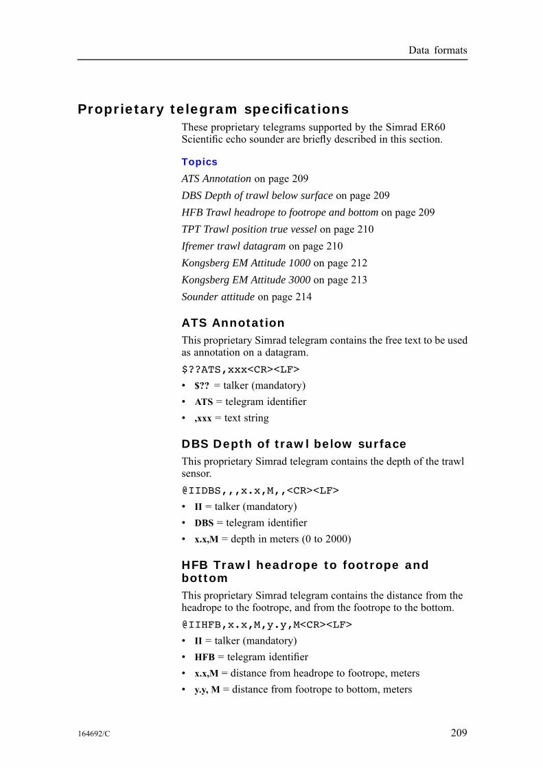
Data formats
Proprietary telegram specificationsThese proprietary telegrams supported by the Simrad ER60Scientific echo sounder are briefly described in this section.
Topics
ATS Annotation on page 209DBS Depth of trawl below surface on page 209HFB Trawl headrope to footrope and bottom on page 209TPT Trawl position true vessel on page 210Ifremer trawl datagram on page 210Kongsberg EM Attitude 1000 on page 212Kongsberg EM Attitude 3000 on page 213Sounder attitude on page 214
ATS AnnotationThis proprietary Simrad telegram contains the free text to be usedas annotation on a datagram.$??ATS,xxx<CR><LF>
• $?? = talker (mandatory)• ATS = telegram identifier• ,xxx = text string
DBS Depth of trawl below surfaceThis proprietary Simrad telegram contains the depth of the trawlsensor.@IIDBS,,,x.x,M,,<CR><LF>
• II = talker (mandatory)• DBS = telegram identifier• x.x,M = depth in meters (0 to 2000)
HFB Trawl headrope to footrope andbottomThis proprietary Simrad telegram contains the distance from theheadrope to the footrope, and from the footrope to the bottom.@IIHFB,x.x,M,y.y,M<CR><LF>
• II = talker (mandatory)• HFB = telegram identifier• x.x,M = distance from headrope to footrope, meters• y.y, M = distance from footrope to bottom, meters
164692/C 209
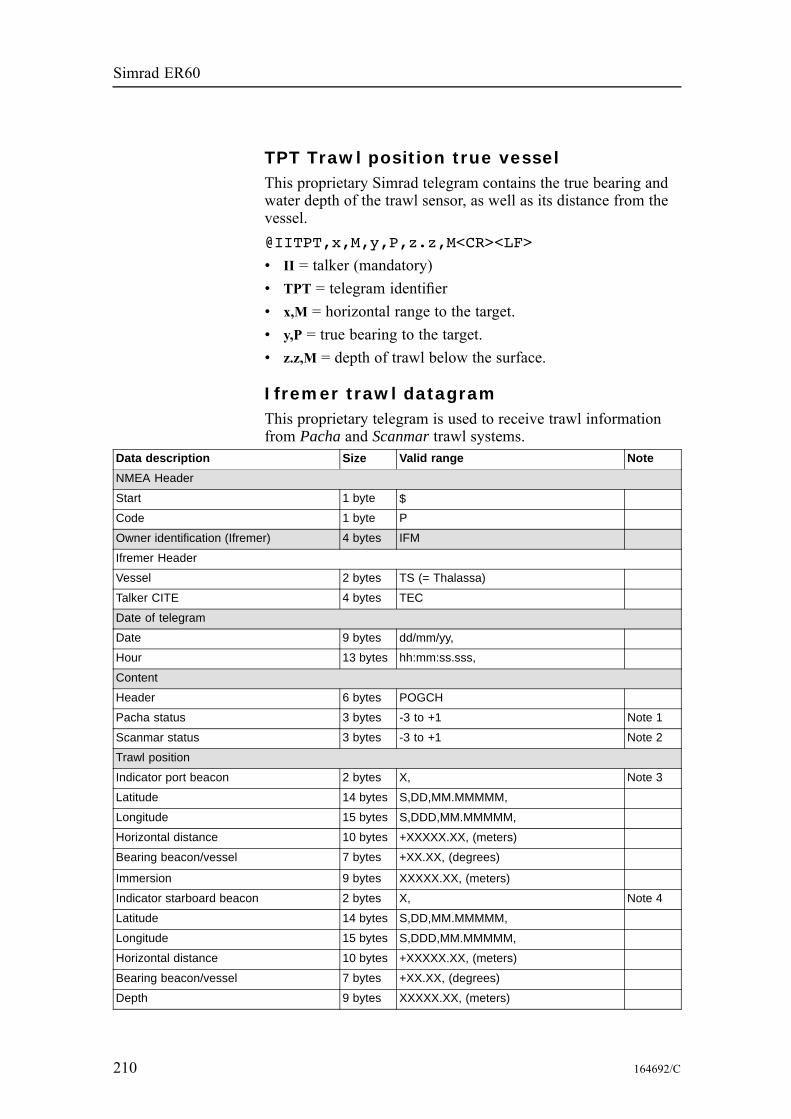
Simrad ER60
TPT Trawl position true vesselThis proprietary Simrad telegram contains the true bearing andwater depth of the trawl sensor, as well as its distance from thevessel.@IITPT,x,M,y,P,z.z,M<CR><LF>
• II = talker (mandatory)• TPT = telegram identifier• x,M = horizontal range to the target.• y,P = true bearing to the target.• z.z,M = depth of trawl below the surface.
Ifremer trawl datagramThis proprietary telegram is used to receive trawl informationfrom Pacha and Scanmar trawl systems.
Data description Size Valid range NoteNMEA Header
Start 1 byte $Code 1 byte P
Owner identification (Ifremer) 4 bytes IFM
Ifremer Header
Vessel 2 bytes TS (= Thalassa)
Talker CITE 4 bytes TEC
Date of telegram
Date 9 bytes dd/mm/yy,
Hour 13 bytes hh:mm:ss.sss,
Content
Header 6 bytes POGCH
Pacha status 3 bytes -3 to +1 Note 1
Scanmar status 3 bytes -3 to +1 Note 2
Trawl position
Indicator port beacon 2 bytes X, Note 3
Latitude 14 bytes S,DD,MM.MMMMM,
Longitude 15 bytes S,DDD,MM.MMMMM,
Horizontal distance 10 bytes +XXXXX.XX, (meters)
Bearing beacon/vessel 7 bytes +XX.XX, (degrees)
Immersion 9 bytes XXXXX.XX, (meters)
Indicator starboard beacon 2 bytes X, Note 4
Latitude 14 bytes S,DD,MM.MMMMM,
Longitude 15 bytes S,DDD,MM.MMMMM,
Horizontal distance 10 bytes +XXXXX.XX, (meters)
Bearing beacon/vessel 7 bytes +XX.XX, (degrees)
Depth 9 bytes XXXXX.XX, (meters)
210 164692/C
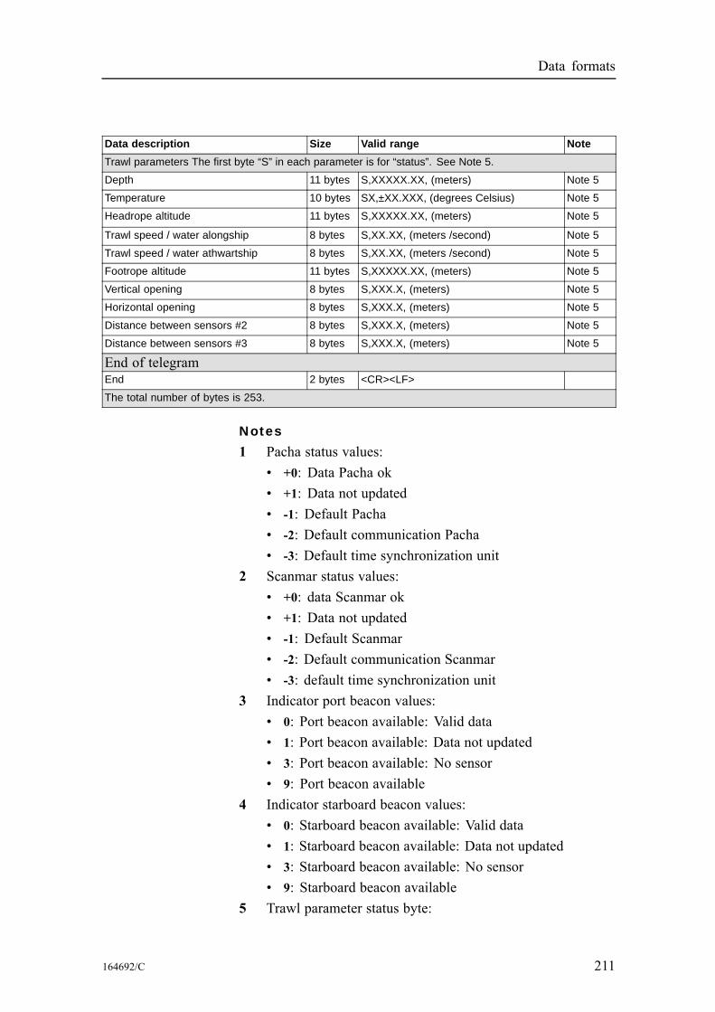
Data formats
Data description Size Valid range NoteTrawl parameters The first byte “S” in each parameter is for “status”. See Note 5.
Depth 11 bytes S,XXXXX.XX, (meters) Note 5
Temperature 10 bytes SX,±XX.XXX, (degrees Celsius) Note 5
Headrope altitude 11 bytes S,XXXXX.XX, (meters) Note 5
Trawl speed / water alongship 8 bytes S,XX.XX, (meters /second) Note 5
Trawl speed / water athwartship 8 bytes S,XX.XX, (meters /second) Note 5
Footrope altitude 11 bytes S,XXXXX.XX, (meters) Note 5
Vertical opening 8 bytes S,XXX.X, (meters) Note 5
Horizontal opening 8 bytes S,XXX.X, (meters) Note 5
Distance between sensors #2 8 bytes S,XXX.X, (meters) Note 5
Distance between sensors #3 8 bytes S,XXX.X, (meters) Note 5
End of telegramEnd 2 bytes <CR><LF>
The total number of bytes is 253.
Notes
1 Pacha status values:• +0: Data Pacha ok• +1: Data not updated• -1: Default Pacha• -2: Default communication Pacha• -3: Default time synchronization unit
2 Scanmar status values:• +0: data Scanmar ok• +1: Data not updated• -1: Default Scanmar• -2: Default communication Scanmar• -3: default time synchronization unit
3 Indicator port beacon values:• 0: Port beacon available: Valid data• 1: Port beacon available: Data not updated• 3: Port beacon available: No sensor• 9: Port beacon available
4 Indicator starboard beacon values:• 0: Starboard beacon available: Valid data• 1: Starboard beacon available: Data not updated• 3: Starboard beacon available: No sensor• 9: Starboard beacon available
5 Trawl parameter status byte:
164692/C 211
Simrad ER60
• 0: Parameter available: Valid data• 1: Parameter available: Data not updated• 2: Parameter available: Problem with acousticinterference
• 3: Parameter available: No data• 9: Parameter available
Kongsberg EM Attitude 1000This proprietary Kongsberg binary telegram consists of a fixedlength 10-bytes message. It is defined as follows:• Byte 1: Sync byte 1 = 00h• Byte 2: Sync byte 2 = 90h• Byte 3: Roll LSB• Byte 4: Roll MSB• Byte 5: Pitch LSB• Byte 6: Pitch MSB• Byte 7: Heave LSB• Byte 8: Heave MSB• Byte 9: Heading LSB• Byte 10: Heading MSBwhere LSB = least significant byte, MSB = most significant byte.All data are in 2’s complement binary, with 0.01° resolution forroll, pitch and heading, and 1 cm resolution for heave.• Roll is positive with port side up with ±179.99° valid range• Pitch is positive with bow up with ±179.99° valid range• Heave is positive up with ±9.99 m valid range• Heading is positive clockwise with 0 to 359.99° valid rangeNon-valid data are assumed when a value is outside the validrange.You can define how roll is assumed to be measured, eitherwith respect to the horizontal plane (the Hippy 120 or TSSconvention), or to the plane tilted by the given pitch angle (i.e. asa rotation angle around the pitch tilted forward pointing x-axis).The latter convention (called Tate-Bryant in the POS/MVdocumentation) is used inside the system in all data displays andin logged data (a transformation is applied if the roll is givenwith respect to the horizontal).Note that heave is displayed and logged as positive downwards(the sign is changed) including roll and pitch induced lever armtranslation to the system’s transmit transducer.
212 164692/C
Data formats
This format was originally designed for use with the EM 950and the EM 1000 multibeam echo sounders with the firstsynchronisation byte always assumed to be zero. The sensormanufacturers was then requested to include sensor status in theformat using the first synchronisation byte for this purpose. Withthis additional information added, the datagram format is knownas “Kongsberg EM Attitude 3000”.
Kongsberg EM Attitude 3000This proprietary Kongsberg binary telegram consists of a fixedlength 10-bytes message. It is defined as follows:• Byte 1: Sync byte 1 = 00h, or Sensor status = 90h-AFh• Byte 2: Sync byte 2 = 90h• Byte 3: Roll LSB• Byte 4: Roll MSB• Byte 5: Pitch LSB• Byte 6: Pitch MSB• Byte 7: Heave LSB• Byte 8: Heave MSB• Byte 9: Heading LSB• Byte 10: Heading MSBwhere LSB = least significant byte, MSB = most significant byte.All data are in 2’s complement binary, with 0.01° resolution forroll, pitch and heading, and 1 cm resolution for heave.• Roll is positive with port side up with ±179.99° valid range• Pitch is positive with bow up with ±179.99° valid range• Heave is positive up with ±9.99 m valid range• Heading is positive clockwise with 0 to 359.99° valid rangeNon-valid data are assumed when a value is outside the validrange.You can define how roll is assumed to be measured, either withrespect to the horizontal plane (theHippy 120 or TSS convention),or to the plane tilted by the given pitch angle (i.e. as a rotationangle around the pitch tilted forward pointing x-axis). The latterconvention (called Tate-Bryant in the POS/MV documentation)is used inside the system in all data displays and in logged data(a transformation is applied if the roll is given with respect tothe horizontal).Note that heave is displayed and logged as positive downwards(the sign is changed) including roll and pitch induced lever armtranslation to the system’s transmit transducer.
164692/C 213
Simrad ER60
This format has previously been used with the EM 950 and theEM 1000 with the first synchronisation byte always assumed tobe zero (Datagram “Kongsberg EM Attitude 1000”). The sensormanufacturers have been requested to include sensor status inthe format using the first synchronisation byte for this purpose.It is thus assumed that:• 90h in the first byte indicates a valid measurement with fullaccuracy
• any value from 91h to 99h indicates valid data with reducedaccuracy (decreasing accuracy with increasing number)
• any value from 9Ah to 9Fh indicates non-valid data but normaloperation (for example configuration or calibration mode)
• and any value from A0h to AFh indicates a sensor error status
Sounder attitudeThe Sounder attitude telegram protocol may be the most commoninterface for heave, roll and pitch compensation. When youselect this protocol, the number of sensor variables is fixed, andthere is no token associated with it. However, baud rate andoutput rate may be adjusted to fit your needs. The format is basedon ASCII characters, the datagrams have fixed length, and it isterminated with a carriage return and line feed.Format:aabbbb shhhhxsrrrr spppp<CR><LF>
• aa = Sway; 2 characters hex number with sway acceleration,in 0.03835 m/ss units
• bbbb = Heave; 4 characters hex number with heaveacceleration, in 0.000625 m/ss units
• s = 1 character with a [space] value if positive, or [-] if negative• hhhh = Heave: 4 characters decimal number with heaveposition in centimetres, positive up
• x = Status character, check the comments below.• s = 1 character with a [space] value if positive, or [-] if negative• rrrr = Roll: 4 character decimal number with roll angle inhundreds of a degree
• s = 1 character with a [space] value if positive, or [-] if negative• pppp = Pitch: 4 character decimal number with pitch anglein hundres of a degree
The definition of the attitude angles in this format is differentfrom the Euler angles definition used elsewhere. The differenceappears in the roll angle, where:
214 164692/C
Data formats
roll arcsin [ sin (roll ) cos (pitch ) ]=echosounder euler euler
The various status characters have the following meanings:• U = Unaided mode and stable data. The sensor operateswithout external input data.
• u = Unaided mode, but unstable data. The sensor is withoutexternal input data, but the data from the sensor is unstable. Aprobable cause for this is the lack of alignment after the sensorhas been switched on restarted. The alignment period from apower recycle is normally approximately five minutes.
• G = Speed aided mode and stable data. The sensor operateswith external input of speed data.
• g = Speed aided mode, but unstable data. The sensor operateswith external input of speed data, but the data from the sensoris unstable. A probable cause for this is the lack of alignmentafter the sensor has been switched on restarted, or a failurein the speed data input.
• H = Heading aided mode and stable data. The sensor operateswith external input of heading data.
• h = Heading aided mode, but unstable data. The sensoroperates with external input of heading data, but the data fromthe sensor is unstable. A probable cause for this is the lack ofalignment after the sensor has been switched on restarted, or afailure in the heading data input.
• F = Full aided mode and stable data. The sensor operates withexternal input of both speed and heading data.
• f = Full aided mode, but unstable data. The sensor operateswith external input of heading and speed data, but the datafrom the sensor is unstable. A probable cause for this isthe lack of alignment after the sensor has been switched onrestarted, or a failure in the heading and/or speed data input.)
164692/C 215

Simrad ER60
12colours, 76
64colours, 76
AAboutfunction, 63HAC, 106users, 163
Access leveldata source, 80users, 163
Activeoperational status, 124
Addplayback file, 144user, 164
Add User Accountdialogue, 64
Administratoruser, 163
Annotationdialogue, 65event, 66NMEA datagrams, 66telegram, 209text input, 66
Annotation Text Inputdialogue, 66
Attitudeheading, 212–213heave, 212–213pitch, 212–213roll, 212–213telegramSounder, 214
Autolog in, 115
BBandwidthoperational status, 124
Baud rateserial linesetup, 147
Bottomlayer properties, 113reference(Echogram), 85
Bottom Detectiondialogue, 67
Bottom Rangedialogue, 69EK500 datagram, 92
Browsefile path
output files, 101
CCalculatesound speed, 94
Calculation Intervaldialogue, 70
Calibrationprocedure, 19
Cascadefunction, 72
Changepassword, 164
Change userdata source, 81
Channelactive, 124depth output, 83disconnecthow to, 15
installationhow to, 15
Channel windowColour scale, 50depth, 45Echogram, 48Numerical, 51Scope, 49Single target histogram, 47Single target position, 46
Channel windowsoverview, 44
Channelshow toset up, 11, 37
ClientRemoting, 142
Close Allfunction, 73
Colour scalepresentation, 76view, 50–51
Colour Scaledialogue, 74short-cut menu, 59–60
Coloursdialogue, 76
Communicationmode, 158(Remoting), 142
parametersethernet output, 98LAN port, 111serial line, 147
CompressionEchogram, 88
Configure Statusbar
dialogue, 77Configure Windowdialogue, 78
ConsoleIP address, 157
Course dataground referencedtelegram, 208
water referenced, 207
DData bitsserial linesetup, 147
Data recordingabout, 16how to, 16
Data replayhow to, 17
Data sourceparameters, 80
Data Sourcedialogue, 80
DatagramNMEAdistance, 93, 104, 121position, 119speed, 120
protocolmotion, 117
tab(EK500 Datagram), 91
Talker IDposition, 119
DBStelegram, 209
Deletesetting file, 114
Delete Layerfunction, 82
Depthreferences(Echogram), 85
short-cut menu, 57transducer installation, 124view, 45
Depth Outputdialogue, 83
Descriptiondata source, 80
DialogueAdd User Account, 64Annotation, 65Annotation Text Input, 66Bottom Detection, 67Bottom Range, 69Calculation Interval, 70
216 164692/C

Index
Colour Scale, 74Colours, 76Configure Statusbar, 77Configure Window, 78Data Source, 80Depth Output, 83Echogram, 84EK500 Datagram, 90Environment, 94Errors, 96, 165Ethernet Output, 97File Output, 100HAC Datagram, 106Histogram, 109Horizontal Axis, 110LAN Port Setup, 111Layer Properties, 112Load Settings, 114Log In, 115Motion, 117Navigation, 118Normal Operation, 124Numerical View, 126Ping Control, 128Port Management, 130Port Monitor, 133Print, 135Print Preview, 136Remoting, 139Replay, 144Save Settings, 146Serial Port Setup, 147Single Target Detection, 148Surface Range, 151Tooltip, 155Transceiver Installation, 156Transducer Parameters, 159Trawl, 160User Properties, 162Users and Passwords, 163Warnings, 165
Displaycolour scalepresentation, 76
number of colourspresentation, 76
organisation, 39–40palettepresentation, 76
views, 39DistanceCalculation Interval, 70Horizontal Axis, 110input, 93, 104, 121manual, 93, 104, 121travelled, 208vesselraw data recording, 102
EEcho trace setupEK500 datagram, 91
Echogramcompression, 88dialogue, 84expansion, 88interpolation, 88rangehow to change, 13
scale lines, 86settinghow to change, 13
short-cut menu, 58view, 48
Echogram channelhow to disconnect, 15how to install, 15
EK500datagram output, 97
EK500 Datagramdialogue, 90
EM Attitudetelegram, 212–213
Environmentdialogue, 94
Errorsdialogue, 96, 165
Ethernet Outputdialogue, 97
Eventannotationinput, 66
Exitfunction, 79, 99
ExpansionEchogram, 88
FFeaturesecho sounder, 9
Filedeletesetting file, 114
namesetting file, 114, 146
pathsetting file, 114
File nameprefixraw data, 102
File Outputdialogue, 100
File sizeraw data recording, 102
Footropedepth
view, 86Frequencychannelabout, 156selection, 157
Frequency channeldepth output, 83
FunctionAbout, 63Cascade, 72Close All, 73Delete Layer, 82Exit, 79, 99Hide View, 108Log Out, 116New Channel, 122New Layer, 123Open All, 127Status bar, 150Tile, 153Tool bar, 154
GGeographicalpositiontelegram, 206
GGAtelegram, 205
GLLtelegram, 206
Global navigation satellitesystemspecific data, 207
Global positioningsystem fixed datatelegram, 205
GNSSspecific data, 207
HHACabout, 106
HAC Datagramdialogue, 106
HDGtelegram, 206
HDMtelegram, 206
HDTtelegram, 207
Headingattitude telegram, 212–213magnetictelegram, 206
relative, 206telegram, 207
164692/C 217

Simrad ER60
telegram, 206Headropedepthview, 86
Heaveattitude telegram, 212–213
Helpmenu, 56
HFBtelegram, 209
Hide Viewfunction, 108
Histogramdialogue, 109properties, 109
Horizontal Axisdialogue, 110
How tocalibrate the echosounder, 19changeechogram range, 13echogram settings, 13vertical resolution, 13
connect multiplexer, 37definemaximum depth, 14minimum depth, 14
disconnect channel, 15install channel, 15measure noise, 32power off, 12power on, 11record raw data, 16replay raw data, 17transceiver channelssetup, 11transceiver setup, 37
IICES, 106Ifremertrawl telegram, 210
Installmenu, 54
Intervalping rate, 128
Introduction, 9IP addressconsole, 157data source, 80local, 158(Ethernet Output), 98(LAN port setup), 111(Remoting), 140, 142
network, 157remote, 158
(Ethernet Output), 98(LAN port setup), 111(Remoting), 142
transceiver, 157
LLabelHorizontal Axis, 110
LAN Port Setupdialogue, 111
Layer Propertiesdialogue, 112
Lineannotationechogram, 87
Linestab(Echogram), 86
Load Settingsdialogue, 114
LocalIP address(Ethernet Output), 98(LAN port setup), 111(Remoting), 140, 142
port(LAN port setup), 111(Remoting), 140
remote(LAN port setup), 111
Log indata source, 81
Log Indialogue, 115
Log outdata source, 81
Log Outfunction, 116
Loopplayback file, 145
MMain menu, 41, 53Manualsound speed, 94
Marginlayer properties, 113
Markerverticalechogram, 87
Maximumdepthhow to define, 14
percentageHistogram, 109
ping rate, 128Menu
Help, 56Install, 54Operation, 53Options, 54Output, 55short-cutColour Scale, 59–60Depth, 57Echogram, 58Scope, 59Single TargetHistogram, 57Single TargetPosition, 57
View, 53Window, 55
Menu system, 52Minimumdepthhow to define, 14
Modecommunication, 158operational status, 124
Modifyuser properties, 164
Motiondialogue, 117input, 117
Multiplexerconnectionprocedure, 37
selection, 157
NNamedata source, 80setting file, 114, 146
Navigationdialogue, 118
NetworkIP address, 157
New Channelfunction, 122
New Layerfunction, 123
NMEAannotationinput, 66
sentencedistance, 93, 104, 121position, 119speed, 120
Noise measurementsprocedure, 32
Normal Operationdialogue, 124
Number
218 164692/C

Index
annotationidentification, 66of colours, 76
Numericalview, 51
Numerical Viewdialogue, 126
OObserveruser, 163
Open Allfunction, 127
Operationmenu, 53
Operatoruser, 163
Optionsmenu, 54
OutputEK500 datagrams, 97menu, 55
PPalettepresentation, 76
Parityserial linesetup, 147
Passiveoperational status, 124
Passwordchange, 164log in, 115
Pathsetting file, 114
Pelagiclayer properties, 113
PingCalculation Interval, 71Horizontal Axis, 110
Ping Controldialogue, 128
Ping ratemodes, 128
Pingingstart/stop, 128
Pitchattitude telegram, 212–213
PixeladjustmentEchogram, 88
Playbackraw datahow to, 17
Playback fileadd, 144
loop, 144remove, 144
Portdepth output, 83local(LAN port setup), 111(Remoting), 140
remote(Ethernet Output), 98(Remoting), 142
Port Managementdialogue, 130
Port Monitordialogue, 133
Positiongeographicaltelegram, 206
GNSS data, 207input, 119system fixed datatelegram, 205
Poweroffprocedure, 12
onprocedure, 11
Presentationcolour scale, 76colours, 76palette, 76
Printdialogue, 135
Print Previewdialogue, 136
Procedurecalibration, 19channel disconnect, 15channel installation, 15connect multiplexer, 37data recording, 16data replay, 17define maximum depth, 14define minimum depth, 14echogram channeldisconnect, 15echogram channelinstallation, 15echogram range, 13echogram settings, 13noise measurements, 32power off, 12power on, 11raw data recording, 16raw data replay, 17set up transceiverchannels, 11, 37vertical resolution, 13
Protocol
sentencemotion, 117
Pulse durationoperational status, 124
RRangeechogramhow to change, 13
layer properties, 112raw data recording, 102tab(EK500 Datagram), 92
Raw datahow to record, 16how to replay, 17recordingabout, 16
Recordingabout, 16raw datahow to, 16
RemoteIP address(Ethernet Output), 98(LAN port setup), 111(Remoting), 142
local(LAN port setup), 111
port(Ethernet Output), 98(Remoting), 142
Remotingdialogue, 139
Removeplayback file, 144user, 164
Replaydialogue, 144raw datahow to, 17
Replay fileadd, 144loop, 145remove, 144
ResolutionHistogram, 109verticalhow to change, 13
RMCtelegram, 207
Rollattitude telegram, 212–213
SSalinitywater
164692/C 219

Simrad ER60
input, 94Sample dataEK500 datagram, 91
Sample intervaloperational status, 124
Saveraw data, 102
Save Settingsdialogue, 146
Scale linesEchogram, 86
Scopeshort-cut menu, 59view, 49
Selectdata source, 81
Serial linesetup, 147
Serial Port Setupdialogue, 147
ServerRemoting, 140
Settingsechogramhow to change, 13
Setupdepth outputcommunication port, 83
Short-cut menuColour Scale, 59–60Depth, 57Echogram, 58Scope, 59Single TargetHistogram, 57Single Target Position, 57
Short-cut menus, 57Simraduser, 163
Single pingtransmission, 128
Single stepping rate, 128
Single Target Detectiondialogue, 148
Single target histogramview, 47
Single Target Histogramshort-cut menu, 57
Single target positionview, 46
Single Target Positionshort-cut menu, 57
Softwareversion, 9
Sound speedinput, 94
Sounder
attitude datagram, 214Speedinput, 120manual, 120
Speed dataground referencedtelegram, 208
water referenced, 207Startpinging, 128
Start Relative Bottomlayer properties, 112
Start Relative Surfacelayer properties, 112
Status barcontent, 43enable, 43, 150function, 150location, 43
Stoppinging, 128
Surfacelayer properties, 113reference(Echogram), 85
Surface Rangedialogue, 151EK500 datagram, 92
Sv thresholdlayer properties, 113
TTalker IDdepth output, 83
Targets Integrationlayer properties, 113
Telegramdepth output, 83
Telegram codeAnnotation, 209DBS, 209EM Attitude 1000, 212EM Attitude 3000, 213GGA, 205GLL, 206HDG, 206HDM, 206HDT, 207HFB, 209Ifremer, 210RMC, 207Sounder attitude, 214TPT, 210VHW, 207VLW, 208VTG, 208
Telegram name
Annotation, 209Course over ground andGround speed, 208Depth of trawl belowsurface, 209Dual ground/waterdistance, 208Geographical positionlatitude/longitude, 206Global positioningsystem fix data, 205Heading, deviation andvariation, 206Heading, magnetic, 206Heading, true, 207Ifremer trawl datagram, 210Kongsberg EM Attitude1000, 212Kongsberg EM Attitude3000, 213Recommendedminimum specificGNSS data, 207Sounder attitude, 214Trawl headrope tofootrope and bottom, 209Trawl position truevessel, 210Water speed andheading, 207
Temperaturewaterinput, 94
Testoperational status, 124
Textannotation, 66echogram, 87
event annotationinput, 66
Ticksechogram, 87
Tilefunction, 153
TimeCalculation Interval, 70Horizontal Axis, 110
Timerevent annotationinput, 66
Tool barEasy Operationenable, 154
function, 154Normal Operationenable, 154
Toolbareasy operation, 42
220 164692/C

Index
location, 42normal operation, 42
Tooltipdialogue, 155
TPTtelegram, 210
Transceiverchannelsset up, 11, 37
information, 157IP address, 157name, 157software version, 157
Transceiver Installationdialogue, 156
Transducerinstallation depth, 124multiplexer, 157parameters, 157selection, 157
Transducer Parametersdialogue, 159
Transmit Poweroperational status, 124
Trawlbottomtelegram, 209
depth, 210telegram, 209
dialogue, 160distancemanual, 161
footropetelegram, 209
headropetelegram, 209
Ifremer datagram, 210input, 160, 164openingmanual, 161
range, 210system, 160, 164true bearingtelegram, 210
Trawl linesEchogram, 86
Tuples, 106Typetab(Echogram), 85
UUDPport number(Ethernet Output), 98
Userrights, 163
User namedata source, 80log in, 115
User Propertiesdialogue, 162
Users and Passwordsdialogue, 163
VVersionsoftware, 9
Verticalmarkerechogram, 87
resolutionhow to change, 13
Vessel distanceraw data recording, 102
VHWtelegram, 207
Viewmenu, 53
VLWtelegram, 208
VTGtelegram, 208
WWarningsdialogue, 165
White lineEchogram, 86
WindowColour scale, 50depth, 45Echogram, 48menu, 55Numerical, 51Scope, 49Single target histogram, 47Single target position, 46
164692/C 221

ISBN-10: 82-8066-011-9
ISBN-13: 978-8066-011-4©2008 Kongsberg Maritime AS
Kongsberg Maritime AS
Strandpromenaden 50
P.O.Box 111
N-3191 Horten, Norway
Simrad
Telephone: +47 33 03 40 00
Telefax: +47 33 04 29 87
www.simrad.com


Sim
rad
ER
60
Scie
ntifi
c ech
o so
un
der so
ftware
Refe
ren
ce m
an
ual
Sim
rad
ER
60
Scie
ntifi
c ech
o so
un
der so
ftware
Refe
ren
ce m
an
ual
Sim
rad
ER
60
Scie
ntifi
c ech
o so
un
der so
ftware
Refe
ren
ce m
an
ual