Embed Size (px)
Citation preview

EM 120Multibeam echo sounder
Product Description


855-160930
EM 120Multibeam echo sounder
Product descriptionThis document presents a brief technical description of theEM 120 multibeam echo sounder.

About this document
Rev Date Written by Checked by Approved by
A 20.05.98 RBr EHa MGj
Original issue.
B 29.05.98 RBr EHa MGj
Minor changes to technical specifications. Mapping examples replaced.One accuracy curve replaced.
C 27.04.99 RBr EHa EHa
Minor changes to document and to technical specifications. System over-view diagram replaced with new version. Preamplifier Unit added.
D 19.11.99 RBr EHa
System overview drawing replaced. Layout in “Technical specifications”reformatted for HTML publishing. Outline dimensions on Tx Junction Boxand Guarantee conditions added to “Technical specifications”.
E 10.11.00 RBr EHa EHa
Several minor changes implemented. Updated outline dimension drawingsadded. Changes to “Technical specifications”. Small errors and misprintscorrected throughout the document.
F 09.04.02 RBr EHa FP
Additional images added, several small corrections to the text.
G 11.11.02 RBr EHa KEN
Minor corrections.
H 18.03.05 EB KEN FP
Implementation of SIS (Seafloor Information System software) and HWS10 (Hydrographic Work Station). Other minor corrections.
© 2005 Kongsberg Maritime AS. All rights reserved.No part of this work covered by the copyright hereon may be reproduced or otherwisecopied without prior permission from Kongsberg Maritime AS.The information contained in this document is subject to change without prior notice.Kongsberg Maritime AS shall not be liable for errors contained herein, or for incidentalor consequential damages in connection with the furnishing, performance, or use of thisdocument.
Strandpromenaden 50P.O.Box 111N-3191 Horten,Norway

Product description
III855-160930 / Rev H
Table of contents
SYSTEM OVERVIEW 1.. . . . . . . . . . . . . . . . . . . . . . . . . . . . . . . . . . . . . . . . .Key facts 1. . . . . . . . . . . . . . . . . . . . . . . . . . . . . . . . . . . . . . . . . . . . . . .System drawing 3. . . . . . . . . . . . . . . . . . . . . . . . . . . . . . . . . . . . . . . . . .System characteristics 4. . . . . . . . . . . . . . . . . . . . . . . . . . . . . . . . . . . . .
PERFORMANCE 7. . . . . . . . . . . . . . . . . . . . . . . . . . . . . . . . . . . . . . . . . . . . . . .Basic specifications 7. . . . . . . . . . . . . . . . . . . . . . . . . . . . . . . . . . . . . . .Pulse lengths 7. . . . . . . . . . . . . . . . . . . . . . . . . . . . . . . . . . . . . . . . . . . .Depth accuracy 8. . . . . . . . . . . . . . . . . . . . . . . . . . . . . . . . . . . . . . . . . .Transducer arrays for individual requirements 9. . . . . . . . . . . . . . . . . .
INSTALLATION 12. . . . . . . . . . . . . . . . . . . . . . . . . . . . . . . . . . . . . . . . . . . . . . .Introduction 12. . . . . . . . . . . . . . . . . . . . . . . . . . . . . . . . . . . . . . . . . . . . .Operator Station and electronic cabinets 12. . . . . . . . . . . . . . . . . . . . . . .Transducer arrays 12. . . . . . . . . . . . . . . . . . . . . . . . . . . . . . . . . . . . . . . .
OPERATION 15. . . . . . . . . . . . . . . . . . . . . . . . . . . . . . . . . . . . . . . . . . . . . . . . . .System features 15. . . . . . . . . . . . . . . . . . . . . . . . . . . . . . . . . . . . . . . . . .Quality control 15. . . . . . . . . . . . . . . . . . . . . . . . . . . . . . . . . . . . . . . . . .Graphical user interface 16. . . . . . . . . . . . . . . . . . . . . . . . . . . . . . . . . . . .Data logging 17. . . . . . . . . . . . . . . . . . . . . . . . . . . . . . . . . . . . . . . . . . . .
POST-PROCESSING 21. . . . . . . . . . . . . . . . . . . . . . . . . . . . . . . . . . . . . . . . . .Post-processing options 21. . . . . . . . . . . . . . . . . . . . . . . . . . . . . . . . . . . .Brief descriptions 21. . . . . . . . . . . . . . . . . . . . . . . . . . . . . . . . . . . . . . . .
CUSTOMER SUPPORT 22. . . . . . . . . . . . . . . . . . . . . . . . . . . . . . . . . . . . . . . .Introduction 22. . . . . . . . . . . . . . . . . . . . . . . . . . . . . . . . . . . . . . . . . . . . .Installation 22. . . . . . . . . . . . . . . . . . . . . . . . . . . . . . . . . . . . . . . . . . . . . .Documentation and training 22. . . . . . . . . . . . . . . . . . . . . . . . . . . . . . . .Service 22. . . . . . . . . . . . . . . . . . . . . . . . . . . . . . . . . . . . . . . . . . . . . . . . .FEMME 23. . . . . . . . . . . . . . . . . . . . . . . . . . . . . . . . . . . . . . . . . . . . . . .Warranty and maintenance contract 23. . . . . . . . . . . . . . . . . . . . . . . . . .
SCOPE OF SUPPLY AND OPTIONS 24. . . . . . . . . . . . . . . . . . . . . . . . . . .Standard system 24. . . . . . . . . . . . . . . . . . . . . . . . . . . . . . . . . . . . . . . . .Options 24. . . . . . . . . . . . . . . . . . . . . . . . . . . . . . . . . . . . . . . . . . . . . . . .System integration 24. . . . . . . . . . . . . . . . . . . . . . . . . . . . . . . . . . . . . . . .
TECHNICAL SPECIFICATIONS 26. . . . . . . . . . . . . . . . . . . . . . . . . . . . . . .Interfaces 26. . . . . . . . . . . . . . . . . . . . . . . . . . . . . . . . . . . . . . . . . . . . . . .Physical specifications 27. . . . . . . . . . . . . . . . . . . . . . . . . . . . . . . . . . . .

EM 120 Multibeam echo sounder
IV 855-160930 / Rev H
Power requirements 28. . . . . . . . . . . . . . . . . . . . . . . . . . . . . . . . . . . . . . .Restrictions for use - limitations 28. . . . . . . . . . . . . . . . . . . . . . . . . . . . .Surface finish 29. . . . . . . . . . . . . . . . . . . . . . . . . . . . . . . . . . . . . . . . . . .Environmental specifications 29. . . . . . . . . . . . . . . . . . . . . . . . . . . . . . .System performance data 29. . . . . . . . . . . . . . . . . . . . . . . . . . . . . . . . . .
COMPANY PROFILE 34. . . . . . . . . . . . . . . . . . . . . . . . . . . . . . . . . . . . . . . . . .Kongsberg Maritime 34. . . . . . . . . . . . . . . . . . . . . . . . . . . . . . . . . . . . . .Kongsberg Group 36. . . . . . . . . . . . . . . . . . . . . . . . . . . . . . . . . . . . . . . .

Product description
1855-160930 / Rev H
SYSTEM OVERVIEW
Key factsThe EM 120 is designed to perform seabed mapping to fullocean depth with an unsurpassed resolution, coverage andaccuracy. The system is cost effective, reliable, and easilyoperated on workstations with familiar operating systems.The design of the EM 120 is based on more than 50 years ofhydrographic experience with echo sounders, sonars andunderwater positioning for civilian and military use. KongsbergMaritime is today a part of the Kongsberg Group, a world wideorganisation supplying advanced instrumentation for civilian,research and military maritime communities.The EM 120 is a complete system. All necessary sensorinterfaces, data displays for quality control and sensorcalibration, seabed visualization, and data logging are a standardpart of the system, as is integrated seabed acoustical imagingcapability (sidescan).Including a shallow water multibeam echo sounder with the EM120 system will give a total system solution meeting IHOrequirements for all depths.
Operating frequency and coverage sector
The nominal sonar frequency is 12 kHz with an angularcoverage sector of up to 150 degrees and 191 beams per ping asnarrow as 1 degree. Achievable swath width on a flat bottomwill normally be up to 5.5 times the water depth. The angularcoverage sector and beam pointing angles may be set to varyautomatically with depth according to achievable coverage. Thismaximizes the number of usable beams. The beam spacing isnormally equidistant with equiangle available.
Transmission
The transmit fan is split in several individual sectors withindependent active steering according to vessel roll, pitch andyaw. This place all soundings on a “best fit” to a lineperpendicular to the survey line, thus ensuring a uniformsampling of the bottom and 100% coverage.

EM 120 Multibeam echo sounder
2 855-160930 / Rev H
The sectors are frequency coded (11.25 to 12.60 kHz), and theyare transmitted sequentially at each ping. The sector steering isfully taken into account when the position and depth of eachsounding is calculated, as is the refraction due to the soundspeed profile, vessel attitude and installation angles. Pulselength and range sampling rate are variable with depth for bestresolution, and in shallow waters due care is taken to the nearfield effects.The ping rate is mainly limited by the round trip travel time inthe water up to a ping rate of 5 Hz.
Transducer arrays
The EM 120 transducers are linear arrays in a Mills crossconfiguration with separate units for transmit and receive. Thearrays are divided into modules, these may be replaced by adiver. The number of modules used (and hence the beamwidth)may be adjusted according to particular installationrequirements. For both arrays 1 and 2 degrees beamwidths arestandard options, and 4 degrees beamwidth is available for thereceive array. The resulting array lengths are between 2 and 8 m.A combination of phase and amplitude detection is used,resulting in an instrument measurement accuracy practicallyindependent of beam pointing angle.
Post-processing
Postprocessing software is available from both KongsbergMaritime and third-party suppliers. A world-wide marketing andservice organization having many years of multibeamexperience is in place for supporting the EM 120.
Optional sub-bottom profiling
The receive transducer is wideband. In conjunction with aseparate low frequency transmit transducer, the EM 120 mayoptionally be able to deliver sub-bottom profiling capabilitieswith a very narrow beamwidth. This system is known as theSBP 120 Sub-Bottom Profiler. For more information, refer tothe dedicated product information.

Product description
3855-160930 / Rev H
System drawing
Figure 1 EM 120 system units and interfaces
Transmit transducer array
Receive transducer array
Interfaces:Positioning systemsAttitude (roll, pitch and heave)HeadingClockTrigger input/outputClock synchronization
8 ---- 24
-- 2424 --
-- 12 -- 12
-- 16(CD
2101
2A)
Sub BottomProfilerTransceiverUnit(Option)
TransceiverUnit
PreamplifierUnit
TX JunctionBox no.1
TX JunctionBox no.2
Remote Control
Optional, may also be connected to the ship's ethernet.
Ethernet
InternalEthernet
OperatorStation
Interfaces:Sound Speed SensorTideCenter depth outputEthernet and serial lines (data i/o)

EM 120 Multibeam echo sounder
4 855-160930 / Rev H
System characteristics
Main units
The EM 120 multibeam echo sounder consists of the followingunits:
• Transmit transducer array (with TX Junction Box(es))
• Receive transducer array
• Transceiver Unit
• Preamplifier Unit
• Operator Station
Figure 2 The Transceiver Unit andTX Junction Boxes on “Bligh”.
A complete mapping system will also include the followingadditional units:
• Vessel motion sensor(s)
• Positioning system(s)
• Sound speed sensor(s)
• Post-processing system
An extra low frequency transmit transducer and transceiver maybe added for the optional high resolution sub-bottom profilingcapability; the SBP 120.

Product description
5855-160930 / Rev H
Transducer arrays
The transmit transducer array contains up to 48 modules inaccordance with the chosen beamwidth. Each module contains18 elements arranged in rows of 6 elements. Each element isindividually connected through the TX Junction Box to itscorresponding transmitter in the Transceiver Unit. It can thus bedriven with an unique amplitude level and phase to allowforming of the required transmit sectors with individual steering.The receive transducer contains up to 16 modules in accordancewith the chosen beamwidth. Each module contains 8 transducerstaves, and these have individual electrical connections to theircorresponding preamplifiers in the Preamplifier Unit. Each stavecan thus be given unique amplitude and phase weighting toallow forming of the required receive beams.The flat and horizontally mounted transducers of the EM 120makes the accuracy almost independent of variations in soundspeed at the transducer depth, unless the roll and pitch are nottoo excessive (exceeding 10 degrees with a 1 m/s sound speederror). Installation of a sensor to allow real-time measurement ofsound speed variation can be made if this is expected, andrecommended if a reduction in angular coverage is unacceptableduring survey in heavy seas. The system will take into accountthe sensor measurements in its calculations of beam pointingangles and raybending. The system is prepared for using anAML Smart Probe directly. Due to possible marine growth, andto ease of cleaning or servicing of the sensor, it would beadvisable to mount the sensor in a tank inside the hull, andpump water taken from the transducer depth through the tank.
Transceiver Unit
The EM 120 Transceiver Unit contains the transmit and receiveelectronics and processors for beamforming, bottom detection,and control of all parameters with respect to gain, ping rate andtransmit angles. It has serial interfaces for all time-criticalexternal sensors such as vessel attitude (roll, pitch, heading andheave), vessel position, and external clock. The Transceiver Unitis a wall mounted cabinet with integrated shock and vibrationabsorbers. The same cabinet is used for all combinations ofbeamwidths. An Ethernet cable connects the Transceiver Unit tothe Operator Station.
Preamplifier Unit
The EM 120 Preamplifier Unit contains the preamplifiers for thereceive signals. The unit also provides the frequency splittingcircuitry to feed low frequency signals to the optionalSub-Bottom Profiler.

EM 120 Multibeam echo sounder
6 855-160930 / Rev H
Tx Junction box(es)
The Tx Junction box serves as an interface routing box for easytransmit transducer cable installation. One or two units must beused depending on the chosen beamwidth.
Operator Station
The Operator Station of the EM 120 is the HWS 10 highperformance dual-processor PC workstation. The operatorsoftware is the Seafloor Information System (SIS). The HWS 10is dual bootable to either Linux® or Windows XP®.SIS allows setting the EM 120 installation and runtimeparameters, data logging and running self-test on the systemwithout restrictions.The SIS software also includes functionality for surveyplanning, 2D and 3D geographical display of the survey results,seabed image and water column displays, plus real-time datacleaning algorithms.The HWS 10 is normally supplied with a 17.4” industrializedLCD monitor with a resolution of 1280x1024 pixels. Supportfor a second monitor is included. A spill-proof US keyboard anda standard optical mouse is normally supplied, but optionally asmall IP 65 rated keyboard with integrated track stick can bedelivered.
SPB 120 Sub-Bottom Profiler (optional)
The EM 120 system may be expanded to include an optionalSBP 120 Sub-Bottom Profiler. The SBP 120 system capabilityincludes the following items:• An additional low frequency transmit transducer array, with
the EM 120 hydrophone array being used for reception• A sub-bottom profiler transceiver unit
• Operator Station(s)
For further information about the SBP 120 system, refer to theapplicable product description.

Product description
7855-160930 / Rev H
PERFORMANCE
Basic specifications
The operating frequency of the EM 120 multibeam echosounder is 12 kHz. This frequency is standard for deep oceanecho sounding, and gives a good balance between reasonablysmall dimensions, narrow beams, and good range capability.
The swath width in shallow waters is typically 6 times the waterdepth to about 2000 m depth. A swath width of about 20 km ormore is generally achievable for deep waters, depending uponbottom conditions and chosen system beamwidths.
The system has 191 beams with pointing angles automaticallyadjusted according to achievable coverage or operator definedlimits. The beam spacing is normally equidistant, correspondingto 1% of depth at 90 degrees angular coverage, 2% at 120degrees and 3% at 140 degrees. Equiangle beam spacing is alsoavailable, as is an in-between spacing.
Pulse lengths
Deep waters
In deep waters a pulse length of 15 ms is normally used. Thetransmit fan is split into nine different sectors transmittedsequentially within the same ping. This method increases thesystem source level, and thus depth and coverage capabilitysignificantly. Using electronic steering, the sectors areindividually tilted alongtrack to take into account the vessel’scurrent roll, pitch and yaw with respect to the survey lineheading. The swath can then be stabilized to fall on a lineperpendicular to the survey line. Pitch and especially yawsteering in individual sectors is required to guarantee 100%bottom coverage in deep waters.
The EM 300 was the first multibeam echo sounderimplementing such yaw steering, while the EM 120 now usesthis technique to reach full ocean depth.
Intermediate depths
At intermediate depths a pulse length of 5 ms is used and thetransmit fan is split in three sectors which are stabilizedaccording to vessel roll, pitch and yaw. Note that yaw steeringmay be required even at a few hundred meters depth despite thehigher ping rate the lesser depth allows.
EM 120 Multibeam echo sounder
8 855-160930 / Rev H
Shallow waters
In shallow waters a pulse length of 2 ms is used, and specialprocessing is used to handle the detrimental near field effects.An increased resolution is then possible, allowing a systemperformance meeting Order 2 IHO accuracy requirements evenat 100 m depth.
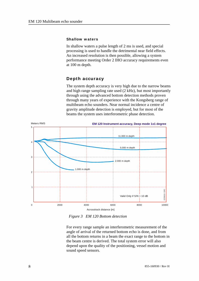
Depth accuracy
The system depth accuracy is very high due to the narrow beamsand high range sampling rate used (2 kHz), but most importantlythrough using the advanced bottom detection methods proventhrough many years of experience with the Kongsberg range ofmultibeam echo sounders. Near normal incidence a centre ofgravity amplitude detection is employed, but for most of thebeams the system uses interferometric phase detection.
Figure 3 EM 120 Bottom detection
EM 120 Instrument accuracy, Deep mode 1x1 degree
5.000 m depth
2.000 m depth
11.000 m depth
1.000 m depth
1
2
3
4
5
0 2000 4000 6000 8000 10000
Acrosstrack distance [m]
Meters RMS
Valid Only if S/N > 10 dB
(CD
5810
/ G
IF)
For every range sample an interferometric measurement of theangle of arrival of the returned bottom echo is done, and fromall the bottom returns in a beam the exact range to the bottom inthe beam centre is derived. The total system error will alsodepend upon the quality of the positioning, vessel motion andsound speed sensors.

Product description
9855-160930 / Rev H
The expected total system RMS accuracy (assuming goodexternal sensor data) is then:• 0.2% of depth (from vertical up to 45 degrees)
• 0.3% of the depth (up to 60 degrees)
• 0.5% of the depth (between 60 and 70 degrees)
Note that the achievable accuracy may be limited by the selectedpulse length (to 0.25 m for 1 ms pulse length, scaleable withpulse length).The signal-to-noise ratio must be better than 10 dB.
Transducer arrays for individualrequirementsSystem accuracy, resolution and coverage capability improveswith decreasing beamwidth, and a beamwidth of 1 x 1 degreewith 8 m long transducer arrays is a standard option for theutmost performance. However, long arrays are expensive andmay be difficult to install, especially with regard to the receivearray which is long athwartship. The transducer array lengthsmay therefore be tailored to individual requirements. Transmitbeamwidth is the most important performance factor, and 1 and2 degrees transmit beamwidths are standard options. For thereceive array 1, 2 and 4 degrees are standard options.The beamwidth of the receive array is normally set to twice thetransmit beamwidth.

EM 120 Multibeam echo sounder
10 855-160930 / Rev H
0
5
10
15
20
25
35
30
Swath width [km] EM 120 Coverage, deep mode 1 x 1 degrees
Gravel [-20 dB]
Sand [-30 dB]
Mud [-40 dB]
0 2000 4000 6000 8000 10000Depth [m]
(CD
4326
A)
0
5
10
15
20
25
30
35Swath width [km] EM 120 Coverage, deep mode 1 x 2 degrees
Gravel [-20 dB]
Sand [-30 dB]
Mud [-40 dB]
0 2000 4000 6000 8000 10000Depth [m]
(CD
4326
B)

Product description
11855-160930 / Rev H
Gravel [-20 dB]
Sand [-30 dB]
Mud [-40 dB]
0 2000 4000 6000 8000 10000Depth [m]
0
5
10
15
20
25
30Swath width [km] EM 120 Coverage, deep mode 2 x 2 degrees
(CD
4326
c)
0
5
10
15
20
25
0 2000 4000 6000 8000 10000Depth [m]
Swath width [km] EM 120 Coverage, deep mode 2 x 4 degrees
Gravel [-20 dB]
Sand [-30 dB]
Mud [-40 dB]
(CD
4326
D)

EM 120 Multibeam echo sounder
12 855-160930 / Rev H
INSTALLATION
IntroductionThe compactness of the EM 120 multibeam echo sounder is aguarantee for a fast and easy installation.
Operator Station and electronic cabinetsThe Operator Station is usually mounted on a desk in theoperation room and suitably tied down. The TX JunctionBox(es) and the Preamplifier Unit are intended to be mountedon a bulkhead in a room close to the transducers to reduce theamount of cabling. The Transceiver Unit is usually installed inthe same room, but may be moved elsewhere to allow for easieraccess.
Transducer arraysThe transducer arrays should be mounted in the forward part ofthe vessel, taking into account hull shape, potential aerationproblems and ease of cable installation.The transducer modules are fixed to a frame with bolts from thefront. The frames may either be mounted directly on or recessedinto the hull, or within sea chests. The latter solution may besomewhat more expensive, but will ensure that the transducersare properly mounted within the tolerances required. A fairingwill usually be added around the transducers to ensure a laminarwater flow without any aeration problems. Ice protectionwindows may be added if required, but angular coverage maythen be restricted.A blister or gondola installation will usually help in avoiding airbubble blockage of the transducers and may contain additionaltransducers for other systems. The receive transducer array maybe folded to fit the vessel’s hull.EM 120 installation examples has been provided.The cables from the modules have a standard length of 20 m,and are terminated with connectors which plug directly into thePreamplifier Unit cabinet. Normally the cables enter the hullthrough tubes which are fitted with standard ship type cableglands (Brattberg or equivalent) to provide water tightness. Thecable glands should be of the type having a pressure rating of 4bars or more. The glands should be installed above the vesselwater-line if diver replacement of transducer modules isenvisioned. If the tubes end below the water-line, classificationrequirements may require a double set of glands.
Product description
13855-160930 / Rev H
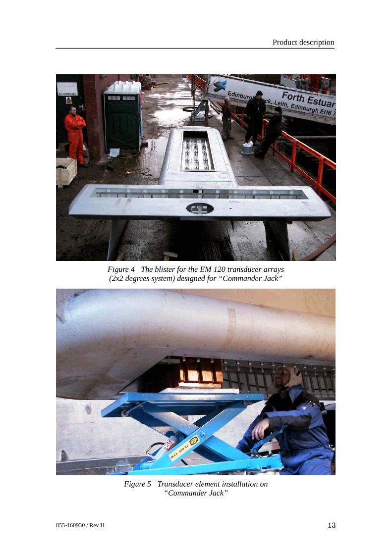
Figure 4 The blister for the EM 120 transducer arrays(2x2 degrees system) designed for “Commander Jack”
Figure 5 Transducer element installation on“Commander Jack”

EM 120 Multibeam echo sounder
14 855-160930 / Rev H
Figure 6 The flush blister for the EM 120 transducer arraydesigned for “James Clark Ross”
Figure 7 Forward view of the transducer blister on “Bligh”.An EM 1002 transducer array is also mounted.

Product description
15855-160930 / Rev H
OPERATION
System featuresThe EM 120 multibeam echo sounder is controlled from theHWS 10 Operator Station using a standard click and pointgraphical user interface. The software, Seafloor InformationSystem (SIS), may either be run under the Microsoft WindowsXP or Linux operating systems which are both installed on theHWS 10. As standard, the system software includes thenecessary features for system installation, testing and runningthe multibeam, ping related displays (including water columndisplay) and the capability of logging the acquired bathymetrydata.The EM 120 system does not require operator interventionduring normal operation, but tracks the bottom automaticallywhile adjusting mode, gain and range dependent parameters asrequired. Before operation is started, the necessary externalsensors, such as positioning and vessel motion sensors, areconnected and calibration procedures followed in order to definethe system and sensor installation parameters.Parameters critical to data quality are password protected, andmost of the parameters can be recalled from a disk file.Seabed imagery data is available from the system as standard.The imagery data, representing the acoustic backscatter strengthof the bottom in 0.5 dB resolution, is available in two forms,one with range resolution nominally corrected for the effect ofincidence angle, the other given per beam as an absolutemeasure. The imagery data may be useful for object detection,but the most important application is probably geophysical forseabed characterization.
Quality controlQuality control of the acquired data is done through graphicaldisplays. In addition a message window and alphanumericdisplays are included to allow a quick overview of the systemstatus, indicating any interface or hardware related problems.SIS provides the graphical displays required for real-timechecking of the EM 120. These include:• Cross-track depth profiles• Beam intensities and quality measures• Time series display of beam samples and sensor values• 3D waterfall display• Sound speed profile display and editor

EM 120 Multibeam echo sounder
16 855-160930 / Rev H
Graphical user interfaceUsing the SIS software, the operator will normally be viewinggridded data in a geographically oriented 2D or 3D display ashis primary means of quality control of the survey. The grid hassix levels of detail, allowing rapid zoom in and out. Previoussurvey results can be imported to allow visualisation of anydifferences between the current and old surveys in overlappingareas.
Figure 8 Example of SIS graphical user interface
The grid may also be utilized for real-time data cleaning. Basedupon a set of user defined rules, outliers in a grid cell, whetherfrom old or new survey lines, are flagged. The flags may beretained or updated through the processing. Optionally theCUBE data-cleaning package from the Center for Coastal andOcean Mapping Center at the University of New Hampshire isalso available in SIS.

Product description
17855-160930 / Rev H
Among other features included are:• System (sensor) calibration• Planning of surveys• Real time cleaning of data, for separate survey lines or for
the complete survey area• Helmsman Display• Full use of the chosen operating system for data export,
plotting and printingElectronic chart data can be displayed as a background in thegeographical displays.
Data loggingIt is of the utmost importance to ensure that all survey relateddata is logged in a safe way. The data is always stored on diskand the geographical displays take data only from disk. In thisway, what the operator sees is what is safeguarded and alreadystored. As standard the HWS 10 runs two high performanceSerialATA disks connected in a RAID1 array, i.e. one disk mayfail without loss of data. The disks are mounted in mobilestorage bays, thus they may be removed for security reasons orfor transporting the acquired data The stored data may bewritten to DVD at any time. The Firewire, SCSI and USBinterfaces may be used for transfer of data to external storagedevices, such as disk or tape, according to user preferences. Alldata are also available on an external Ethernet.The logged data sets include:• Raw sensor data• Beam ranges and beam pointing angles• Depth datagrams
- In each depth datagram range/angle data from one pinghave been merged with motion sensor data and the currentsound velocity profile to derive a rigorous solution forvessel motion and raybending, calculating sounding depthand position as Cartesian coordinates. The depthdatagrams are suited for immediate presentation in thegeographical display.
• Seabed image data• System parameter settingsThe gridded data (terrain model) is also available for logging.The data formats are public and published on the KongsbergMaritime web site, ensuring that EM 120 is a truly opensolution, allowing third party or own software to be developedfor data processing.

EM 120 Multibeam echo sounder
18 855-160930 / Rev H
Figure 9 Bathymetry contours,survey example from “Jan Mayen”,courtesy of the NorwegianPetroleum Directorate
Figure 10 Sonar mosaic, surveyexample from “Jan Mayen”,courtesy of the NorwegianPetroleum Directorate

Product description
19855-160930 / Rev H
Figure 11 Survey example from “Roger Revelle”
EM 120 Multibeam echo sounder
20 855-160930 / Rev H
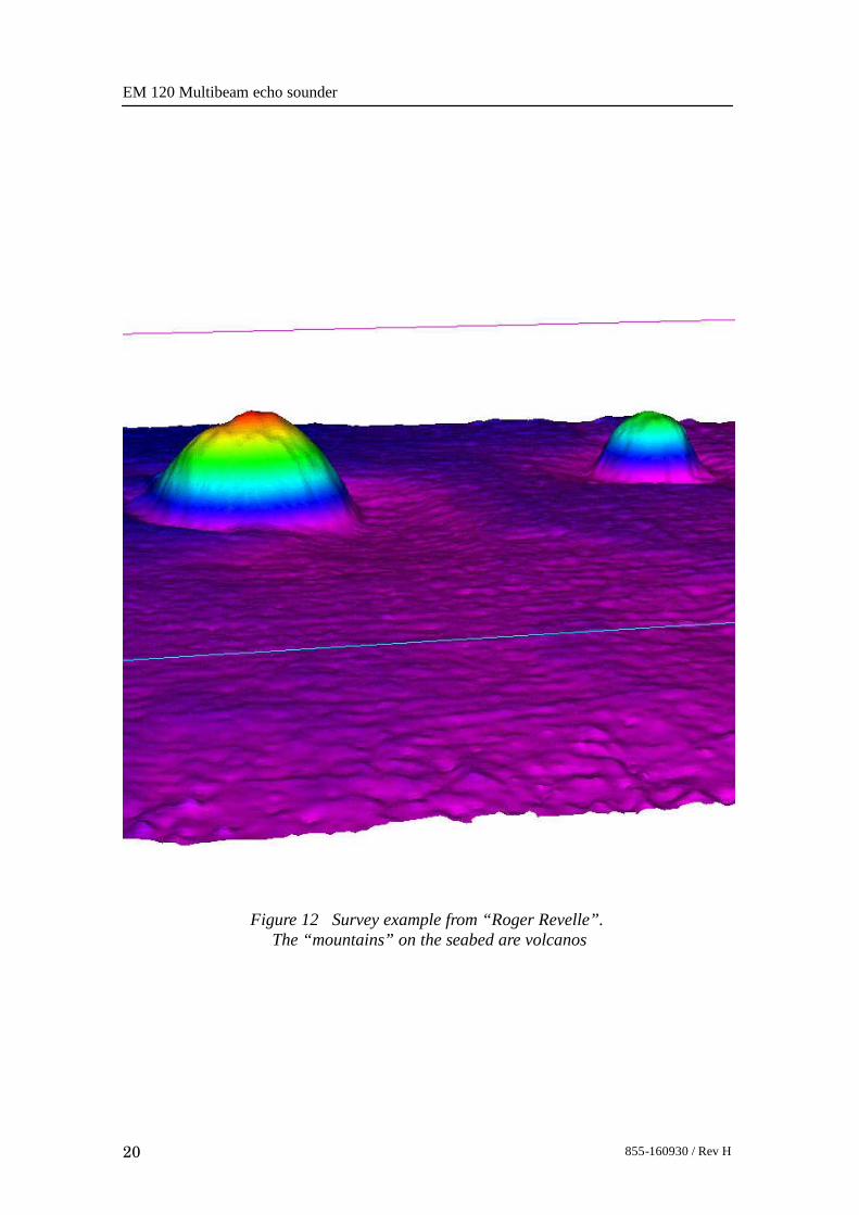
Figure 12 Survey example from “Roger Revelle”.The “mountains” on the seabed are volcanos

Product description
21855-160930 / Rev H
POST-PROCESSING
Post-processing optionsThe high quality data produced by the EM 120 multibeam echosounder is an excellent basis for producing a completedescription of the seabed in the form of charts, 3D displays,combined bathymetry and acoustic imagery, seabedclassification, etc. Kongsberg Maritime can deliver a completeset of products for post-processing EM 120 bathymetric data.Interfaces to other post-processing software is also available.
Brief descriptionsThe Neptune software is used for post-processing ofbathymetric data. Such post-processing involves cleaning andfiltering of position data, analysis and corrections for depth data,tidal height adjustment, automated data cleaning based uponstatistical rules, manual editing, controlled data thinning, andexport of the final sounding data to further processing.The Poseidon software is used for post-processing of seabedimage data into seabed image mosaic map overlay. Thisinvolves merging of data from overlapping survey lines,applying systematic corrections which are required, filtering andinterpolation.The Triton software is used for seabed sediment classification.This process extracts signal features from the seabed image data,and applies this data to a statistical classification procedure inorder to obtain the best estimate for seabed sediment type as afunction of position in the form of a map overlay. The classifiercan be trained and adapted to local conditions by use of atraining module to correlate acoustical signature to ground truthinformation.Software to be used for digital terrain modelling and plotgeneration can be delivered integrated with Neptune to derive adigital terrain model from an interpolation of the cleanedsounding data. From the terrain model contour maps, 3D plots,depth profiles along specified routes, fairsheets, volumecalculations, etc, are easily produced. This additional third-partysoftware is usually the Cfloor system.

EM 120 Multibeam echo sounder
22 855-160930 / Rev H
CUSTOMER SUPPORT
IntroductionAs a major supplier of multibeam echo sounders with manyyears of experience, Kongsberg Maritime has developed amarketing and service organization tuned to customer needs.
InstallationAs part of the discussions with the client Kongsberg Maritimewill - free of charge and without any obligations - give adviceregarding the practical installation of the EM 120 system. Wewill also - upon request - prepare proposals for the supply ofcomplete instrument packages and/or systems. A projectmanager will usually be appointed to supervise the delivery,installation and testing of larger instrumentation systems.The installation and final testing of an EM 120 system shouldbe done according to Kongsberg Maritime’s documentation. Ifrequired, Kongsberg Maritime field engineers can be madeavailable to:• Supervise the installation.• Perform the measurement of final location and attitude of the
transducers and/or sensors.• Perform system check-out and final testing.
Documentation and trainingThe EM 120 is delivered with complete documentation forinstallation, operation and maintenance. If required, the manualsare prepared to reflect the actual system on the client’s vessel.Kongsberg Maritime can conduct the training of operators andmaintenance personnel to the extent required by the client. Suchtraining courses can take place on the vessel, on any ofKongsberg Maritime’s facilities, or any other location decidedby the client.
ServiceThe Kongsberg Maritime service department has a 24 hour dutyarrangement, and can thus be contacted by telephone at anytime. The service department will assist in solving all problemsthat may be encountered during the operation of the system,whether the problem is caused by finger trouble, insufficientdocumentation, software bugs or equipment breakdown.

Product description
23855-160930 / Rev H
FEMMEA forum for users of Kongsberg Maritime’s multibeam echosounder systems (FEMME), with the aim of improvingcommunication both between the users and KongsbergMaritime, but also between the system users, is arranged atapproximately 18 months intervals. Close to 100% userparticipation has been experienced at these meetings.
Warranty and maintenance contractThe normal warranty period of the EM 120 is 24 months afterdelivery.A system maintenance contract tailored to fit the needs of theclient is available. This contract can be defined so that it coversrepair work only, or complete support for preventivemaintenance, repair work, and system upgrading of bothhardware and software as the system design is improved byKongsberg Maritime.The maintenance contract could also include a life-timewarranty of transducers, upgrading of spare parts anddocumentation, and repeated or additional training courses.

EM 120 Multibeam echo sounder
24 855-160930 / Rev H
SCOPE OF SUPPLY AND OPTIONS
Standard systemA basic EM 120 multibeam echo sounder delivery includes:1 Operator Station HWS 10 with 17.4” LCD monitor.2 Transducer modules.
These include necessary cables and mounting frames inaccordance with chosen beamwidths.
3 Preamplifier Unit.4 Transceiver Unit.5 TX Junction Box(es).6 Signal and control cables between cabinets. Standard
length is 5 m.7 All system software.8 System manuals covering system installation, operation
and maintenance.
OptionsSystem options available include:• Sea chests for transducers.• Ice protection windows (may limit angular coverage).• Raw data recorder.• Non-standard cable lengths between the the TX Junction
Box(es), Preamplifier Unit and Transceiver Unit. Maximumlength is 25 m.
• Helmsman Display and/or additional monitors.• Postscript colour graphic printer/plotter.• High resolution grayscale recorder for continuous seabed
image hardcopy.• Spare parts.• SPB 120 Sub-Bottom Profiler system.
System integrationComplimentary to the EM 120, the following software productsmay be delivered:• Neptune for post-processing of bathymetric data.• Cfloor integrated with Neptune for digital terrain modelling.

Product description
25855-160930 / Rev H
• Triton for seabed classification.
• Poseidon for seabed image mosaicing.
Additionally Kongsberg Maritime may deliver the EM 120 aspart of a complete survey system. This may include integrationwith single beam echo sounders and/or other multibeam echosounders for seamless coverage of any depth range.An integrated system may share electronic chart display(ECDIS), dynamic positioning and vessel management systems,and third-party equipment such as sound speed sensors, vesselmotion sensor and positioning systems.
EM 120 Multibeam echo sounder
26 855-160930 / Rev H
TECHNICAL SPECIFICATIONS
Note Kongsberg Maritime is engaged in continuous developments ofits products and reserves the right to alter specifications withoutprior notice.
Interfaces• Serial lines with operator adjustable baud rate, parity, data
length and stop bit length for:- Motion sensor (roll, pitch, heave and optionally heading)
in format supported by sensors from Applanix, iXSEA,Kongsberg Seatex and VT TSS
- Heading (gyrocompass) in either NMEA 0183 HDT orSKR82/LR60 or Sperry Mk39 format
- Positions in either Simrad 90, NMEA 0183 GGA or GGKformat
- External clock in NMEA 0183 ZDA format- Sound speed at transducer- Sea level height (tide)- Single beam echo sounder depths- Output of depth straight down in NMEA 0183 DPT
format• Interface for 1PPS (pulse per second) clock synchronisation
signal• SCSI interface intended for tape drive
• Firewire interface for external data storage device (tape ordisk)
• USB 2.0 interfaces for data storage, printing or plotting
• Parallel interface for Postscript colour graphics printer/plotter
• Ethernet interface for input of sound speed profile, tide andecho sounder depths, and output of all data normally loggedto disk

Product description
27855-160930 / Rev H
Physical specifications
Transmit transducer
• Module:- Length: 178.6 mm / 131.4 mm- Width: 760 mm (780 mm with frame)- Height: 197 mm (261.5 mm with 1 degree frame, 249.5
mm with 2 degrees frame)- Weight: 58 kg
• Frame length:- 4020 mm (2 degrees)- 7770 mm (1 degree)
Receive transducer
• Module:- Length: 447 mm- Width: 342 mm (420 mm with frame)- Height: 120 mm (177 mm with frame)- Weight: 24 kg
• Frame length:- 1808 mm (4 degrees)- 3600 mm (2 degrees)- 7200 mm (1 degree)
Transceiver Unit
• Height: 1760 mm• Width: 600 mm• Depth: 630 mm• Weight: Approximately 197 kg
Preamplifier Unit
• Height: 920 mm• Width: 600 mm• Depth: 630 mm• Weight: Approximately 96 kg
TX Junction Box
• Height: 440 mm• Width: 500 mm• Depth: 303 mm• Weight: Approximately 15 kg

EM 120 Multibeam echo sounder
28 855-160930 / Rev H
Operator Station
• Height: 127 mm• Width: 427 mm (excluding rack fixing brackets)• Depth: 480 mm (excluding handles and connectors)• Weight: Approximately 20 kg
LCD monitor
• Height: 400 mm (excluding mounting brackets)• Width: 460 mm (excluding mounting brackets)• Depth: 71 mm (excluding mounting brackets)• Weight: 9.2 kg
Power requirements• Fuse: The single phase supply must be protected with 16A
slow-blow fuses.• Operational voltage and frequency:
- Transceiver Unit: 115 or 230 Vac (±10%), < 1100 W, 47to 63 Hz
- Operator Station: 110 or 240 Vac (±10%), < 250 W, 47to 63 Hz
- LCD monitor: 110 or 240 Vac (±10%), < 60 W, 47 to 63Hz
- Preamplifier Unit: 110 or 240 Vac (±10%), < 300 W, 47to 63 Hz
- TX Junction Box: None
Note For 110 Vac operation, please [email protected]
• Acceptable transients:- Short time (max 2 sec): ±25%, 42 to 69 Hz- Spikes (max 50 µS): < 1000 V
• Power interrupts: Menu settings, all parameters and thesound speed profile are stored on the Operator Station’sharddisk during operation, so operation can continue afterpower interruption. However, the file system may bedamaged, so the use of an uninterruptable power supply(UPS) is higly recommended.
Restrictions for use - limitationsNo specific restrictions apply.

Product description
29855-160930 / Rev H
Surface finishAll cabinets are painted. System units exposed to salt watermust be treated accordingly.
Environmental specifications• IP rating:
- Transceiver Unit: IP54- Preamplifier Unit: IP54- Operator Station: IP22- LCD Monitor: IP22
• Operating temperatures:- Transceiver Unit: 0 to +45_C- Preamplifier Unit: 0 to +40_C- Operator Station: 5 to +55_C
• Storage temperatures:- Transceiver Unit: -30 to +70_C- Preamplifier Unit: -30 to +70_C- Operator Station: -30 to +70_C
System performance data• Main operational frequency: 12 kHz
- Frequencies in the range of 11.25 to 12.60 kHz areemployed to code the different transmit sectors.
• Maximum ping rate: 5 Hz• Number of beams for each ping: 191• Beamwidths: 1x1, 1x2, 2x2 or 2x4 degrees
- Other beamwidth combinations are are possible inaccordance with the number of transducer modulesinstalled.
• Beam spacing: Equidistant or equiangle• Coverage sector: Up to 150 degrees• Transmit beam steering: Stabilized for roll, pitch and yaw• Receive beam steering: Stabilized for roll• Depth range from transducers: 20 to 11.000 metres• Depth resolution: 10 to 40 cm• Pulse lengths: 2, 5 and 15 ms• Range sampling rate: 2 kHz (37 cm)

EM 120 Multibeam echo sounder
30 855-160930 / Rev H
830-211291Rev.A
Page 1 of 2(CD5646) Transceiver Unit, outline dimensions

Product description
31855-160930 / Rev H
830-211291Rev.A
Page 2 of 2(CD5646) Transceiver Unit, outline dimensions

EM 120 Multibeam echo sounder
32 855-160930 / Rev H
830-213112Rev.B
Page 1 of 1(CD5649) Preamplifier Unit, outline dimensions
Weight: Approx. 96 kgAll measurements in mm.

Product description
33855-160930 / Rev H
830-213111Rev.B
Page 1 of 1(CD5648) TX Junction Box, outline dimensions
Weight: Approx 15.5 kgAll measurements in mm.

EM 120 Multibeam echo sounder
34 855-160930 / Rev H
COMPANY PROFILE
Kongsberg Maritime
Kongsberg Maritime is a leading supplier of advanced maritimeautomation and instrumentation systems. The company hasapproximately 2400 employees and an annual turnover ofMNOK 3.700 (year 2004). Kongsberg Maritime ownssubsidiaries in Canada, Italy, the Netherlands, Germany,Sweden, Singapore, China, Korea, the UK and the USA inaddition to four locations in Norway. Decentralisation letssubsidiary company optimise customer relationships whileproviding maximum flexibility in relation to product design,production and marketing. Kongsberg Maritime currentlyexports its products to all of the world’s major markets.
Figure 13 Kongsberg Maritime’s facilities in Horten.

Product description
35855-160930 / Rev H
Kongsberg Maritime’s main office is situated in Horten,Norway. The Hydroacoustics department responsible for thedesign and production of the EM 120 is also located in Horten,close to the Oslo fjord. Sharing premises with Simrad AS,producer of echo sounder and sonars for the world’s fishingfleet, the companies also share more than 50 years of experiencein single and multibeam echo sounding, sonar technology andunderwater communication and instrumentation.Kongsberg Maritime’s location close to the waterfront providesexcellent surroundings for the design, test and manufacturing ofthe advanced products. Two in-house test tanks, a sea based teststation as well as two vessels are available for extensive testingand quality control.
Figure 14 The test and demonstration yacht “M/K Simrad Echo”
The product range provided by Kongsberg Maritime in Hortenincludes:• Single and multibeam echo sounders for hydrographic use• Underwater communication• Underwater positioning reference systems (including the
highly accurate HiPAPR system)• Naval sonars and echo sounders (hull mounted and towed
systems)• Oil and gas simulator systemsKongsberg Maritime is fully owned by the Kongsberg Group.

EM 120 Multibeam echo sounder
36 855-160930 / Rev H
Kongsberg GroupKongsberg Gruppen ASA (the Kongsberg Group) is one ofNorway’s leading high-technology companies. With an annualturnover of approximately MNOK 6.400 (in 2004), it is listed atthe Oslo Stock Exchange. The largest shareholder is theNorwegian Ministry of Industry and Energy holding 51% of theshares. The rest is publicly owned.The Kongsberg Group operates through two major businessareas:• Kongsberg Defence & Aerospace AS• Kongsberg Maritime ASThese companies are fully owned by the Kongsberg Group.Kongsberg Defence & Aerospace is engaged in defenceactivities, while the commercial market activities are allocatedwithin Kongsberg Maritime.The Kongsberg Group is represented world wide.For more information, visit www.kongsberg.com


E 2005 Kongsberg Maritime