Embed Size (px)
Citation preview

Scheme to improve transient responseof industrial systems
S.N. Fisher, B.Sc, and W.H. Jewell, C.Eng., M.I.E.E.
Indexing terms: Power systems and plant, Transients
Abstract: This paper is based on recent electrical system studies carried out on an Imperial Chemical Indus-tries (ICI) plant located in Scotland, which derives its power supplies from both in-house generators and gridinterconnection. The objective was to examine methods of improving the transient response of the industrialsystem under various external and internal fault conditions, with a view to improving the security of suppliesto important drives and auxiliaries. High levels of plant security and enhanced synchronous-generator stabilityare normally associated with multiple-grid and in-house distribution feeders, with corresponding low valuesof impedance between the supply sources and motor drives. However, this paper examines all aspects ofsystem behaviour during fault conditions and concludes that, in this instance, an improvement to overalltransient performance is achieved by increasing grid feeder reactance immediately after fault inception. Inthe case of external faults developing on the interconnected grid, computer-aided studies show the advantageof rapidly switching out one of the grid transformer feeders. Similarly, in the event of selected internal faultsoccurring, study results show the improvement achieved by rapidly opening normally closed ring mains,thereby doubling the effective ring feeder reactance.
1 Introduction
Industrial process plants normally require very high levelsof electrical security to be maintained during both steady-state and transient conditions. This is particularly relevantfor a continuous, as opposed to batch, process since theunscheduled shutdown of a small number of critical electricmotor drives could result in unstable process conditionsarising, thus initiating the automatic shutdown of thecomplete process. In cases of more serious transient dis-turbances, the process may sustain a 'crash' shutdown,possibly leading to plant damage, but certainly involvingwider disruption to auxiliary and services systems. Thus,the time required to restart the plant and re-establish stableprocess conditions can range from hours up to days, and itmay result in very high cost penalties.1
Hence, for an interconnected industrial complex that hasin-house turbine-driven generators installed, it is normalto adopt a design philosophy based on the retention ofin-house generation to provide power to essential suppliesin the event of a very onerous transient fault conditionarising. On this basis it is often possible to either avoid acomplete process shutdown, or at least to ensure that anyunavoidable plant shutdowns are accomplished in a pro-grammed and safe manner, thereby enabling an earlyrestart to be achieved when main grid supplies are restored.This technique is known as an 'island' running condition,and is a well-proven design method.
Such designs may typically include the transition ofin-house set governing from back pressure to speed controlon the loss of grid supplies, in conjunction with the auto-matic load shedding of nonessential drives. Reaccelerationschemes may also be included to aid speedy recovery of thesystem. The correct selection and setting of electricalprotection equipment is also important to ensure thesuccess of such schemes.
In the case of the ICI plant in Scotland, the design of the
Paper 898B, first received 28th March and in revised form 3rd July1980Mr. Fisher is with Imperial Chemical Industries Limited, Petro-chemicals Division Headquarters, Wilton, Cleveland, England, andMr. Jewell is with Ewbank and Partners Limited, ConsultingEngineers, Brighton, Sussex
IEEPROC, Vol. 127, Pt. B, No. 6, NOVEMBER 1980
electrical supply system was basically sound and includedmost of the conventional features described above. However,the requirement to review the system security arose from ahistorical record of occasional, yet recurring, partial, orcomplete, plant shutdowns, and the decision to examine thepossibility of effecting an improvement to plant securityduring transient fault conditions. In this situation, anymajor plant-design changes are rarely feasible, or necessary.
However, there is often scope for improving the overalltransient response by approaching the problem withoutpreconceived ideas, and examining the particular systemindetail, since designs and circumstances can vary considerablyfor different plants. In this context, the term overalltransient response includes not only the stability ofsynchronous generators (or motors), but also the slip ofrunning induction motors and per unit transient voltagelevel during both the fault and immediate postfaultperiods.2
This paper describes how such an approach was adoptedfor the ICI plant in Scotland, and describes the method-ology leading to innovative design proposals for a schemeto improve plant security under selected external andinternal fault conditions. The scheme is based on increasingfeeder reactance immediately after fault inception.
2 Methodology and fault records
Where historical fault records are available, the best startingpoint is to analyse this data and carry out computer-aideddynamic studies to simulate typical fault conditions andinvestigate corresponding plant behaviour for differentrealistic prefault operating conditions.
This historical information provides art excellent insightinto the types of fault which occur most frequently, andwhich faults cause partial, or complete, shutdown of servicesor process plant. The sequence of shutdown is also veryimportant. For instance, the tripping of in-house servicegenerators during a closeup fault may be caused by loss ofstability, an overspeed condition, or simply failure tomaintain minimum control oil-pressure conditions owing tothe increased slip of an a.c.-control oil-pump motor driveduring a transient undervoltage condition. It is appreciatedthat a well-designed modern plant should not allow the last
349
0143-7038/80/060349 + 09 $01-50/0

two conditions to arise; however, in practice, such con-ditions do occasionally arise on existing plants. Since eachof these shutdown mechanisms may require a different tech-nique to remedy the problem and improve security, itfollows that considerable advantages may accrue fromreferring to site records which schedule the fault events.Records of consequential loss of production, any additionalenergy costs, or damage, provide a useful basis for derivingeconomic justifications for any proposed schemes toimprove transient response and hence security.
Very comprehensive fault records were available for theICI plant in Scotland. The results of this fault analysis canbe summarised very briefly as follows:
(a) External faults accounted for the majority of plantshutdowns, although the faults were mostly of a fairlyshort duration (< 0-5 s) and were generally only associatedwith the partial shutdown of selected process plants. Itappeared that lightning strokes were mainly responsible forthese shutdowns.
(b) Although internal 11 kV fault occurrences were lessfrequent than external system faults, the fault duration wasnormally increased to one second or more, and a completeshutdown of both services and process plant sometimesresulted.
Another useful and more accurate source of transientdisturbance data can be provided by the installation ofevent oscillograph recorders. This equipment can establishboth prefault steady-state and postfault transient records ofcurrent and voltage inputs, as well as providing eventmarkers to monitor the sequence of circuit breaker tripsetc. ICI have recently installed two such instruments at oneo£their other UK plants.
Subsequent sections describe how the interconnectedSystem' was modelled on computer programs and the studiescarried out to investigate the effect of representative faultconditions on system transient performance,3"9 together
132kV grid system
earthing tx.TIB T2B
'60 MVA 60 MVAJ21 J21
33kV substation
33/11kVfeeders(via o/hlines)
11kV substation
main 11kV substation
T1 T221 MVA 21MVAJ103 j103
l.p. h.p. f©25MVA Q ici
|x'd80°/o | system
ji—L
11'KV services and works plantswitchboards equipped similarlyto bd.1
Fig. 1 Schematic of interconnected system
All impedance values % to 100 MVA base
350
with methods adopted to develop a novel protectionscheme based on the introduction of increased reactance.
3 System modelling
The ICI plant in Scotland is interconnected with the gridvia two 21 MVA 33/11 kV transformer feeders. Since thisindustrial complex is a large steam user, the installationincludes two steam-turbine generators to offset energycosts. A simplified arrangement of the interconnectedsystem is shown in Fig. 1, and this also shows the imped-ance values of main plant.
It will be appreciated that a more comprehensive repre-sentation is used to model a system in computer-aideddynamic studies than the simplified schematic shown.
3.1 Modelling in-house industrial plant
For the ICI plant, the majority of plant loads compriseinduction motors which were scheduled to identify essentialand nonessential drives. In this instance, there are nosynchronous motors.. A maximum plant load of 28 MW and18 Mvar has been represented, to include services auxiliaries.It is also necessary to identify the type of driven unit,which for study purposes can generally be classified intothree groups:
(a) Centrifugal drives — pumps etc., torque proportionalto speed squared.
(Z>) Fan drives — again torque is proportional to speedsquared, but characterised by very high inertia constants.
(c) Reciprocating drives — compressors etc., constanttorque characteristic, and thus prone to stalling undersystem undervoltage conditions when pullout torque isexceeded.
In this case, the total reciprocating drive load summatesto 3-5 MW, of which 1 MW constitutes part of the essentialload. All the loads have been represented as inductionmotors, and for simplicity they have been modelled asbeing directly connected to the 11 kV ring-main switch-boards. Whereas the peak torque of a 415 V motor wouldtypically be within 2-5 x f.l.t., Fig. 2 shows that the charac-teristics of the motor model adopted includes a high peak-torque value of 3-2. The reason for selecting this value and
load/torque characteristicsreciprocating drives \
load/torque characteristicscentrifugal drives \
10
Fig. 2 Torque/slip and current I slip characteristics of induction-motor model, and load/torque characteristics
IEEPROC, Vol. 127, Pt. B, No. 6, NOVEMBER 1980
shape of torque/slip characteristic was to ensure the systemmotor loads draw high Mvar demands as the slip increases,thereby representing an onerous transient study conditionto provide a pessimistic bias to the results. For many typesof studies, it is necessary to base motor models at eachvoltage level on actual machine-equivalent circuit andinertia data, to be provided by the manufacturers. However,in this instance, a simplified and more expeditious approachbased on a single-motor model was acceptable because thestudies concentrate on the derivation of overall systemperformance, with particular emphasis on transient voltagelevels, rather than the accurate prediction of individualmotor slips.
The active and reactive power outputs of the 25 MVAback-pressure generators have been represented throughoutmost of the studies at values of 11 MW/8 Mvar (h.p. set) and16MW/12Mvar (l.p. set) to represent normal operatingconditions. Comprehensive design data for the turbinegenerators and associated excitation equipment was pro-vided by the manufacturer, to enable accurate computermodelling of the machines.
Each study has been carried out to represent normaloperating conditions with both 132/33 kV and 33/11 kVgrid transformers initially connected, both in-house 25 MVAgenerators connected, and the inner and outer industrialcomplex 11 kV services/process plant rings run closed.
For the loading conditions described, it will be notedthat under normal operation there is no significant importof power from the grid; in fact, there is a minor export ofreactive Mvar. Hence this system provides ideal scope foroptimising on the phased disconnection of the 33/11 kVgrid feeders under external fault conditions, since withboth in-house generators in service the industrial complexcan survive as an isolated 'island' without even the require-ment to implement automatic load-shedding. Where appro-priate, the effect of load shedding resulting from thesimulated dropoff of a.c.-held contactors during lowtransient voltage levels has been represented in the studies.
In the more usual case, where a significant grid importnormally prevails, the design philosophy would be verysimilar, although any proposal to trip both feeders wouldinvariably require the initiation of programmed loadshedding to avoid overloading the in-house generators.
In any event, it will be appreciated that the practice ofcomplete disconnection from the grid should be avoidedwherever possible, since there could be a prior outageof selected in-house generators, with resultant need forload shedding, apart from the risk of failure of the islandsystem during transition of in-house set governors fromback-pressure to speed-control mode, plus the need toresynchronise on restoration of external supplies.
3.2 Modelling grid supply network
It is usually necessary to commence investigations byobtaining predicted grid fault incident rates, system faultlevels and representation, protection co-ordination anddetails of earthing practices. Typical clearance times, toinclude circuit-breaker opening times, for the discon-nection of 33 kV and 11 kV faults, are shown in Table 1.
Since dynamic stability conditions under both sym-metrical and unbalanced fault conditions are being investi-gated, it is necessary to obtain the positive-, negative- andzero-sequence impedance representation of the gridnetwork.
IEEPROC, Vol. 127, Pt. B, No. 6, NOVEMBER 1980
Voltage
33
11
Table 1 :
level, kV
Typical protection clearance times
Protection
mainback-upmainback-up
Total clearance time, s
0-21-1-5
2-5-34
4 External faults and introduction of phasedtransformer-feeder tripping scheme
4.1 Type and duration of faults
This Section of the paper includes investigations intoexternal fault mechanisms, together with system studiesto examine the effect of both external symmetrical andunbalanced faults on the security of both the ICI worksservices and process plant, and includes proposals to effectimprovements.
Initial studies quickly showed that most 132kV or11 kV faults on the grid system would be sufficientlyelectrically remote as to have no significant effect on theintegrity of the industrial complex, provided the in-housegenerator a.v.r.s were functioning correctly. Hence, it isonly necessary to examine 33 kV fault conditions in furtherdetail.
As mentioned in an earlier Section, investigations indi-cated that the more severe voltage depressions weregenerally associated with 33 kV overhead line lightningstrokes on feeders to other users. The frequency of theselightning strokes was somewhat high since several of theoverhead lines followed a fairly exposed route.
The 33 kV conductor support structures comprisedunearthed wood poles, horizontal steel crossarms and pininsulators. The average impulse flashover value for a Balticfir wood pole would be typcially 045kV/mm, but couldreduce to as low as 0-1 kV/mm during wet surface-trackingconditions. However since, as shown in Fig. 1, the 33 kVsystem neutral is earthed via high-impedance earthingtransformers, the earth-fault currents are very low andshould not prove to be a problem. However, the con-structional features of these overhead lines would permitsingle-phase faults to fairly readily develop into the moresevere type of two- or three-phase faults, and later studyresults show that a multiphase 33 kV fault would be com-patible with the recorded voltage levels at the ICI plant11 kV switchboard when selected process plant shutdownsoccurred.
A line-to-line fault condition is very similar to a line-to-line-to-ground fault. Such phase-to-phase faults would rarelybe self extinguishing, and the ionised arc would normallybe cleared by electrical protection equipment.
Published information for the performance of typical33 kV lines indicates that up to a total of ten directlightning strokes and induced overvoltage flashover faultscan occur per 100 kilometres per year,10 which generallyaligns with the several multiphase faults per year experi-enced in the vicinity of the ICI plant in Scotland.
Symmetrical and unbalanced fault studies have beencarried out to determine the industrial complex transientvoltage levels, currents, generator rotor swings and theabsolute slip of running motors during the occurrence ofvarious external faults.
Study results showed that 33 kV line-to-ground faultshave virtually no effect on the industrial complex 11 kVvoltage levels, and that the fault current contributionthrough each 21 MVA 33/1 lkV transformer remains less
351

than 3 MVA 3-phase equivalent, which is less than 15% ofthe transformer ratings.
Further study results showed that 33 kV line-to-groundand line-to-line-to-ground faults, cleared within a typicalgrid main protection time of 0-2 s, would not result inexcessive generator rotor swings or running motor slips.The 3-phase voltage vectors at the main industrial complexl l k V switchboard remain symmetrical to within 12°and the phase voltage to neutral magnitudes are 0-85 p.u.,0-85 p.u. and 0-71 p.u. for the red, blue and yellow phases,respectively, immediately before fault clearance. The post-voltage recovery is satisfactory without any load shedding.
Fig. 3 shows that if the disconnection of this type offault is delayed until l-5s, representing the limit of gridbackup protection clearance time for 33 kV faults, then themagnitude of the industrial complex 11 kV phase voltagevectors to neutral falls to 0-77 p.u., 0-77 p.u. and 0-65 p.u.for phases red, blue and yellow, respectively, with bothin-house generators in service and a.v.r.s operative. Thecorresponding 33/11 kV transformer feeder branch phasecurrent magnitudes increase to over 60 MVA and 38 MVA
"£ j l.p.25MVAset-5? 40-, h.p.25MVAset
l a1
8"
£ o
reciprocating drives
nonreciprocating drives
10-
0 8-
R.v Bthrough each 33/11
I kV transformer
-i-0|g0-4 08 1-2 *16 2 0 2 A
fault on fault offtime.s
c
Fig. 3 l-5s duration, type line-to-line-to-ground fault on grid33kV substation. Phases yellow and blue shorted to earth duringfault
a Generator rotor swingsb Absolute slip of running motorsc Transient voltages and currentsSubscripts B, R and Y indicate blue, red and yellow phases,respectively
export for the faulted yellow and blue phases respectivelybefore fault clearance. Generator rotor swings and motorslips are again not a problem, and the postfault voltagerecovery is fairly satisfactory.
Symmetrical fault study results showed that the onlysignificantly adverse effect of 0*2 s duration line-to-line-to-line 33 kV faults is the voltage depression at the 11 kVbusbars to 0-6 p.u. immediately before fault clearance. Forthis reason, it is very advantageous to effect fast clearancefor this type of fault, as discussed later.
Fig. 4 shows the very adverse effect of a 15s duration33 kV 3-phase fault on the industrial works services andprocess plant. Although the generators should retainsynchronous stability (ignoring the effect of any turbine-generator auxiliary failure on generator integrity) it willbe noted that the 11 kV voltage levels fall to the very lowvalues of 0-54p.u. at the main l l k V switchboard and0-50 p.u. at the six services/process ring main switchboards.It will also be noted that these 11 kV voltage levels fall toapproximately 06p.u. within 0-2s. The slip of runningmotors increases to just over 10% and 8% for the repre-sentative reciprocating and non-reciprocating drives,respectively, which could possibly result in the stalling ofselected drives, depending on the actual electrical-motorand mechanical-load torque design characteristics.
4.2 Control equipment dropoff characteristics
At these voltage levels, many a.c.-held (nonlatched) con-tactors would be expected to trip several of the processdrives. The ICI 415 V contactors comply with the earlierBS 775: Part 1, 'Contactors for voltages up to and including1000 volts a.c. and 1200 volts d.c.', which states thatcontactor dropoff should only occur for voltages below0-75 p.u.
In practice, the dropoff characteristics of contactors willvary considerably with manufacturer and type, with respectto both voltage magnitude and dropoff time delay. Duringunbalanced fault conditions the contactor performance willbe influenced by the phase connections of the contactorcoils, which are normally connected between phase andneutral for medium voltage plant, although they may beconnected between phases. Hence, any contactor dropoffsimulations in computer studies can only be deemed asapproximate if dropoff predictions are based on 11 kV p.u.voltage levels.
The cumulative curve in Fig. 5 was derived from a testprogramme carried out on 230 contactors, and shows thedropoff characteristics for this group which was installedon another ICI plant. This curve shows a threshold ofcontactor dropoff at a 67% voltage level; also that thesecontactors drop off in the range 67% down to 30% voltage,the majority dropping off at around 50% volts.
Actual site tests are normally required to ascertain thecontactor dropoff characteristics for a particular workssituation, and checks are needed to establish the extentof secure latched or d.c.-held contactors.
In the instance of the ICI plant, no firm contactordropoff data was available, so predictions were based on theFig. 5 curve.
The voltage level at which control circuits fail also variesconsiderably for different manufacturing types, normaloperating voltages, and whether the supply is a.c. or d.c.Process-plant control circuits are normally designed on afail-safe basis, such that plant shutdowns can occur onpartial or complete loss of continual supplies. Hence, it
352 IEEPROC, Vol. 127, Pt. B, No. 6, NOVEMBER 1980

would again be necessary to carry out actual site tests toestablish what voltage depression levels can be toleratedwithout prejudicing plant security.
4.3 Investigations to improve system transient response
It will be noted from the foregoing, that, for the conditions
40-
12-
nonreciprocating drives-.
5 i ring-main switchboardo O"A"
02
0-4 0-8 12 11-6 2 0
fault on fault ontime.s
c
Fig. 4 1 -5s duration, type line-to-line-to-line fault on grid 33kVsubstation
a Generator rotor swingsb Absolute slip of running motorsc Transient voltages
IEEPROC, Vol. 127, Pt. B, No. 6, NOVEMBER 1980
studied, with both 33/1 lkV transformers and in-housegenerators in service, then if an external line-line-line, orpossibly even a line-line or line-line-ground 33 kV faultpersists for more than 02s , the security of both servicesand process plant can be adversely affected, mainly becauseof undervoltage conditions developing on the works system.Should such an external fault not be cleared within its mainprotection period of 0 2 s, then it is not possible for theindustrial user to install a standard backup protectionscheme to clear the fault quickly without the risk of indis-criminate disconnection from the grid. However, it ispossible to design a special backup protection schemewhich is initiated by directional overcurrent relays, andinitially rapidly disconnects only one of the two 33/11 kVtransformers when a severe external multiphase fault hasbeen detected. This disconnection procedure rapidlyintroduces additional impedance between the externalfault and the industrial complex system in order to improvevoltage levels, and hence plant security.
Since, for the system under study, the power transferacross the two 21MVA33/llkV transformers will onlybe nominal, there would normally be no significant dis-advantages in tripping one of the incoming 33/11 kVfeeders in a very fast time, denoted as stage 1, which isfaster than the grid main protection clearance time of0-2 s. Since this stage 1 time setting is not required to dis-criminate with the grid main protection, it can be set toa very short duration, subject to the avoidance of nuisancetripping in the event of minor very short duration systemdisturbances occurring. In this study, a Stage 1 trippingtime of 150 ms has been assumed, which is based on an11 kV circuit-breaker opening time of 80 ms and a fast-acting directional relay time of 10 ms, and a timer settingof 60 ms.
Comparison of the results presented in Figs. 4 and 6shows the considerable improvement to the transient-voltage profiles if one 33/11 kV transformer is rapidlytripped at around 015 s, even for an uncleared 33 kVclose-up line-line-line fault, and could prevent the occur-rence of significant contact dropoff; motor slips are alsoconsiderably reduced.
However, the improved system voltage levels wouldresult in increased dynamic-motor load reacceleratingdemands, with a corresponding small adverse effect ongenerator stability. Fig. 6 shows that it is doubtful whethersynchronous stability would be maintained between thein-house generators and the grid if the external protectiondid not clear the 33 kV fault within 1 -2 s.
For this reason, it would be preferable to disconnect thesecond 33/11 kV transformer in a fairly fast time of, say,
percentage dropoff (volts)
F ig. 5 Typical contactor dropoff characteristics353

10s (in the event of grid main protection not operating) toenable the in-house generators to remain operative andmaintain the majority of industrial complex supplies under'island' running conditions.
Hence the effect of stage 1 (015 s) and stage 2 (10 s)disconnection times for the first and second 33/11 kVtransformer feeders results in the satisfactory dynamic
40-
-LP25MVAset
-HP25MVAset
in-house generators
disconnected from grid
8-
10
11kV ring-mainswitchboards '
current througheach33/11kVtx.
current throughremaining33/ilkV tx.
I("80 ^I u -
[eofj
— CO
0-4 0-8 A 12 16 20Ltrip 1st 33/11kV tx. Mrlp 2nd 33/11kV tx.
fault on time.sc
Fig. 6 Uncleared type line-to-line-to-line fault on grid 33 kVsubstation. 33/11 kV transformers tripped after 015 and l-0s
a Generator rotor swingsb Absolute slip of running motorsc Transient voltages and currents
performance of the services and process plant throughoutthe more onerous multiphase external faults.
It is also necessary to consider initial system operatingconditions, where both 33/11 kV transformers are inservice, but only one in-house generator is connected. Basedon a total works load demand of 28MW at 085p.f.(i.e. 33MVA) and initial operation of the connectedin-house generator at, say, 20MVA output, then withoutany load shed or contactor dropoff due to low volts, anoverload of approximately 13MVA could exist if both33/11 kV transformers were tripped. However, in practicethe ICI plant in Scotland would not normally choose tomaintain maximum throughput in the event of a generatoroutage due to energy charges, and furthermore, under-voltage conditions could be assumed to automaticallydisconnect less-essential loads owing to contactor dropoffetc. For this reason, it is not considered necessary oradvisable in this case to inhibit operation of the directionalovercurrent tripping scheme in the event of a prior outageof an in-house generator, and the risk of a possible gener-ator overload trip is acknowledged.
4.4 Design of enhanced protection scheme
The magnitude of 33/11 kV transformer l.v. branch phasecurrent for both the line-line and line-line-line faults readilyenables discrimination with the nonimportant line-groundfaults for the initiation of directional overcurrent trips.
Fig. 7 shows a suitable directional overcurrent protectionscheme (d.o.c.) to provide Stage 1 and 2 tripping of the twoincoming grid feeders in order to improve the security ofthe industrial plant during the occurrence of sustainedexternal grid multiphase faults. The sequential tripping ofthe two incoming circuit breakers is simplified by hard-wiring stage 1 and 2 trip circuitry to the grid feeders 1 and2, respectively. Further logic is included to prevent stage 1timer initiation in the event of one 33/11 kV transformer
R Y B[o/c relays set
Ireactive currenti i
overcurrentelement(50-2007o)
0-0-5s(set=006s)
to d.o.c. relays onno. 2 incomer
11kV circuit-breakertrip circuits
stage 2
Fig. 7 Directional overcurrent scheme for stages 1 and 2 tripping3311 lkVgrid incomers
354 1EEPROC, Vol. 127, Pt. B, No. 6, NOVEMBER 1980

being initially out of service, yet allowing the stage 2 timertrip to operate in all conditions.
To meet the foregoing derived timing requirement asaccurately as possible for varying magnitudes of line-to-lineand line-to-line-to-line 33 kV fault branch currents, it isnecessary to specify overcurrent elements which operate ina short duration, ideally in a definite time. This require-ment is best met by a responsive relay which operates in therange of approximately 10—20 ms for currents in excess ofsetting. Timers are included in the d.o.c. scheme to providethe corresponding stage 1 and 2 delay times. A setting ofapproximately 0-75 p.u. reactive output current has beenrecommended to prevent operation under grid 33 kVline-to-ground or any healthy reactive export conditionsfrom the industrial complex.
A specified operating angle of 45° for the directionalelements is designed to ensure satisfactory operatingtorques within the operate zone, and yet inhibit relayoperation for any internal fault or normal load variations.
The installation of this d.o.c. protection scheme alsoprovides a useful record of the type and approximateduration of any external fault occurrences, and for thisreason flagged relays are recommended.
5 Internal faults and introduction of ring-splittingscheme
5. / Performance o f existing system
A similar approach has been adopted to examine the possi-bility of improving plant security in the event of selectedonerous internal faults occurring, particularly since thehistorical fault records showed that internal faults generallypersist for a longer duration and sometimes cause a com-plete works shutdown to occur.
As discused in this Section, investigations and systemstudies confirmed that the 11 kV ring-main services andprocess-plant switchboards included slow-acting protectionequipment which would permit widespread tripping in theevent of infrequent multiphase l l k V faults. However, inview of the very low inception rate of this type of faultthere was not sufficient justification to undertake anymajor protection improvement programme, particularlysince it would be very difficult to obtain access to oper-ating circuits. To overcome these restrictions, a novelscheme was developed which was cheap and easy to install,and was based on the rapid introduction of additionalimpedance between the faulted ring switchboard and the'healthy' plant motor drives, immediately a severe faulthad been detected.
Because of space restrictions, only a brief descriptionof this scheme is included in this paper, and it is ack-nowledged that in the instance of the ICI plant in Scotland,the existing ring-main feeder reactance values are somewhatlow and result in the proposed ring-splitting scheme onlyachieving a marginal recovery of essential drives. However,the design philosophy is a useful sequel to Section 4, andcould have an application on other networks with suitablefeeder reactance values.
Fig. 8 shows a key protection diagram for the 11 kVring-main switchboards. Early calculations showed thatsince all unit drive and distribution step-down transformersare rated less than 1 MVA, then due to the correspondinglyhigh reactance, any l.v. fault will not seriously affectdynamic conditions at the main distribution 11 kV voltagelevel. Hence such a fault would not cause widespreadtripping of plant, and is not pursued further.
IEEPROC, Vol. 127, Pt. B, No. 6, NOVEMBER 1980
The following circuits are equipped with fast operatingprotection equipment, which would normally effect faultclearance within 0 2s:
(a) main 11 kV switchboard — equipped with bus-zoneprotection
(b) 11 kV feeder cables — equipped with Solkor Rprotection
(c) unit motor drives - equipped with high-set over-current protection to clear 11 kV faults
System studies verified that, subject to confirmation,essential services and process drives are supplied via latchedor d.c.-held contactors, and then essential plant shouldnormally ride through 11 kV line-to-line-to-line faults seenby the above protection.
The following circuits were identified as being equippedwith relatively slow-acting protection equipment:
(a) ring-main services and process-plant 11 kV switch-
j80
main 11kV switchboard
2o.ci.t
e.i.t.
filkr only one ring shown
j 30-4
<1MV/
j 30-A
-X-swbd. 2
equipped as switchboard 1
Fig. 8 Existing ring-main protection scheme
e.f.f.s.l.k.r.h.s.o.c.
p.h.O.I.
t.l.f.1
= earth fault= unit feeder Solkor R= high-set overcurrent= phase unbalance= thermal overload= time-log fuse= i.d.m.t. overcurrent and earth fault
355

boards - equipped with i.d jn.t. overcurrent and earth-faultprotection
(b) 11/0-415 kV distribution transformer feeders —equipped with time-lag fuse overcurrent and earth-faultprotection
Protection grading checks revealed that faults on thesecircuits could result in slow fault-clearance times, such that,for a fault on switchboard 1, the relay A (Fig. 8) wouldcause the ring main to split in 0 4s, with disconnection(via relay B in Fig. 8) of the faulted switchboard in a totaltime of approximately 1 -2 s. System studies predictablyconfirmed that these slow clearance times would result intotal system collapse, as also confirmed by historicalfault records.
5.2 Development of enhanced protection scheme
Consideration was initially given to the introduction ofdirectional overcurrent relays in the ring mains, but pro-tection grading checks indicated that no correspondingimprovement to fault-clearance times would result. Henceit was pertinent to seek an alternative solution to the instal-lation of bus-zone protection on the six 11 kV ring-mainswitchboards and high-speed protection on the 11/0-415 kVdistribution transformer feeders.
The system study results for the above 0-4/1-2 s slowfault-clearance case were analysed in order to obtain abetter understanding of the actual cause of works shut-downs. This showed that shutdowns would occur mainlybecause of extremely low voltage levels developing on allsix 11 kV ring-main switchboards. Although the stabilityof in-house generators would be retained, the slip of motorson the nonfaulted ring main increases to over 18% forreciprocating drives and 15% for centrifugal drives; muchhigher slips in the range 22—28% are developed on the tworemaining switchboards connected to the faulted ring.Hence all motors would probably stall (or crawl), par-ticularly since the post-fault voltage recovery is unsatis-factory. It will also be appreciated that such stall con-ditions could also trip the in-house generators via loss ofa.c. essential auxiliaries such as control oil supplies. Furtherstudies showed that the introduction of load shedding onlyachieved a minor improvement.
Basic voltage profile calculations were carried out topredict the effect of splitting a ring main immediately an11 kV line-to-line-to-line fault developed on one of the11 kV ring switchboards. These results showed a significantimprovement to the voltage level of all nonfaulted switch-boards. Referring to Fig. 8, it can be seen that both ringfeeders include a reactor with a value of 30-4% on 100 MVAbase, which reduces to 15-2% for the normal condition ofparallel feeder operation. Hence by introducing a scheme torapidly split the faulted ring at the centre switchboardbus-section circuit breaker (location C in Fig. 8) shortlyafter fault inception, the system impedance between thefaulted-plant switchboard and main switchboard source ofgeneration is doubled, and the fault thereby becomeselectrically more remote from all nonfaulted ring-mainswitchboards. Hence investigations showed that, whereasfor reasons of security and voltage drop considerationsduring the direct-online start of large motor drives, thepolicy of running the ring mains normally closed duringsteady-state conditions is correct, a distinct advantagecould be shown by rapidly opening the rings duringselected fault conditions.
Consideration was then given to the fastest feasibleoperation of the ring-split feature to maintain discrimi-nation with the existing ring-feeder Solkor R zone pro-tection, and to a lesser degree the existing unit drive high-set overcurrent protection. Failure to discriminate with theformer could result in the loss of supply to healthy switch-boards, and the latter would only cause the unnecessaryopening of the ring main under unit drive h.v. main pro-tection operating conditions. Investigations showed that,although very fast operation (within 0-2 s) of the ring-splitscheme was required to avoid a complete works shutdown,the need to discriminate with feeder cable Solkor R pro-tection (together with its associated circuit-breaker openingtime) required the ring split to be delayed to around 0-3 s.This problem was resolved by introducing a feature toblock bus-section trip signals in the event of any Solkor Rrelay operating. On this basis, ring-split operating times of160 and 225 ms were established to maintain discriminationwith the Solkor R and unit drive high-set protection relays,respectively.
In this study, the nonessential maintenance of discrimi-nation with unit drive high-set protection has been adopted,and results in the slower clearance time of 0-225 s. An over-current and earth-fault relay with a low overshoot charac-teristic has been selected for this bus-section trip function.An overcurrent setting of 1800 A has been selected, whichensures operation under minimum generation conditions,yet discriminates against spurious operation during motor-start or plant-reacceleration conditions. The introductionof this ring-split relay also enables an improvementto overall protection grading, such that total fault dis-connection time is reduced from 1-2 to 0-9 s.
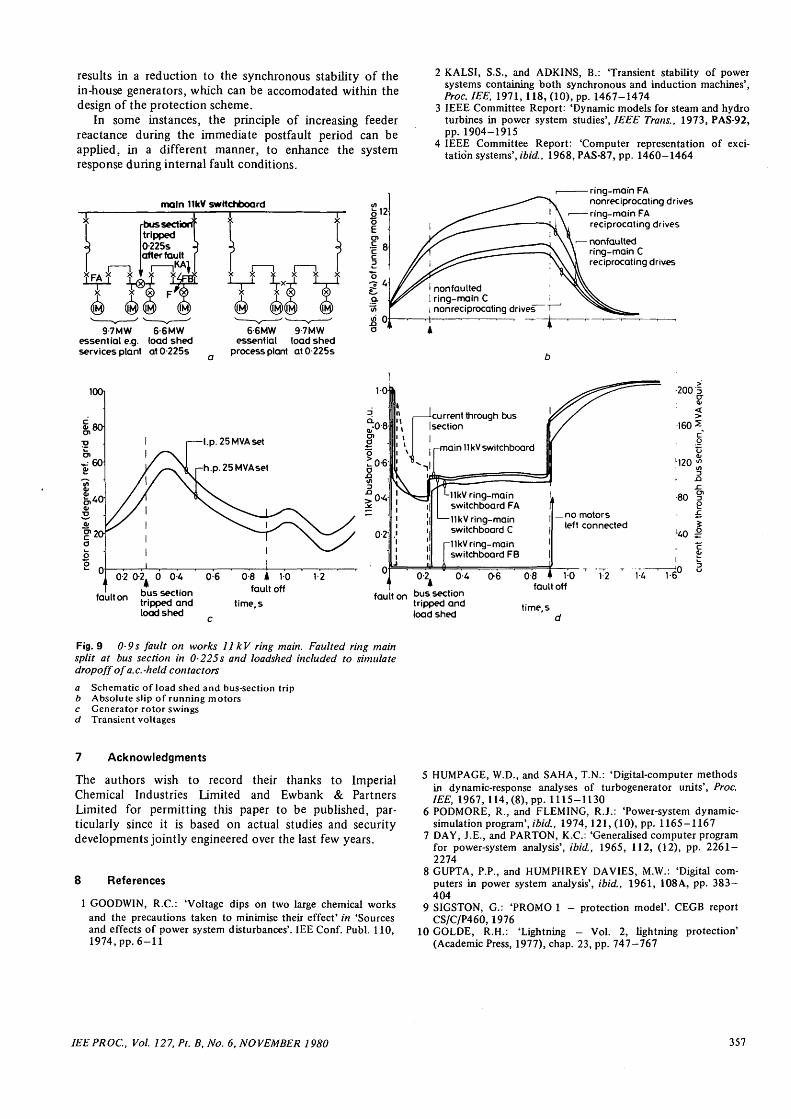
Fig. 9 shows that, during the period 0-225 to 0-9 s,when the faulted switchboard is split, the voltage of thenonfaulted switchboards is improved to approximately0-5 p.u. (when allowance is made for a 50% load-shed tosimulate the effect of a.c.-held contactor dropoff). It canbe seen that, for this condition, the essential drives whichare fitted with latched contactors should be able to justride through the fault without disconnection. Good post-fault voltage recovery is achieved, though motor slipscould increase to reasonably high values in the range7—13%. It will be appreciated that higher values of ringreactance would effect yet further improvements to overalldynamic stability under these internal fault conditions. Itwould also be advantageous, wherever possible, to installprotection equipment (such as instantaneous undervoltage)to ensure the early trip of nonessential reciprocating driveswhich tend to 'brake' the system.
6 Conclusions
The paper shows that where industrial systems derive theirpower supplies from both in-house generators and gridinterconnection, the overall plant security level may beimproved during external fault conditions by increasing thegrid feeder reactance immediately after fault inception. Thiscan be achieved by the installation of a directional over-current scheme, designed to rapidly trip one of the gridtransformer feeders when an external multiphase fault isdetected. The improved overall transient response isachieved by reducing the severity of voltage drops at plantswitchboards, thereby minimising the extent of disturb-ances caused by contactor dropoff and stalling motors.However, the increased reactance of the grid connections
356 IEEPROC, Vol. 127, Pt. B, No. 6, NOVEMBER 1980
results in a reduction to the synchronous stability of thein-house generators, which can be accomodated within thedesign of the protection scheme.
In some instances, the principle of increasing feederreactance during the immediate postfault period can beapplied, in a different manner, to enhance the systemresponse during internal fault conditions.
2 KALSI, S.S., and ADKINS, B.: Transient stability of powersystems containing both synchronous and induction machines',Proc. IEE, 1971, 118, (10), pp. 1467-1474
3 IEEE Committee Report: 'Dynamic models for steam and hydroturbines in power system studies', IEEE Trans., 1973, PAS-92,pp. 1904-1915
4 IEEE Committee Report: 'Computer representation of exci-tation systems', ibid., 1968, PAS-87, pp. 1460-1464
main 11kV switchboard
-bus sect ioriftripped I0-225s Aafter fault r
9-7MW 6-6MWessential e.g. load shedservices plant atO-225s
6-6MW 9-7MWessential load shed
process plant at 0 225s
o12
ring-main FAnonreciprocating drivesring-main FAreciprocating drives
nonfaultedring-main Creciprocating drives
nonfaultedring-main Cnonreciprocating drives"
100i
5
u 0
-l.p. 25MVAset
-h.p.25MVAset
02 0-2 0 0U 0 6
fault on bus sectiontripped andload shed
08 A 10
fault off
time.s
12
Ilkv ring-mainswitchboard FA
—Ilkv ring-mainswitchboard C
Ilkv ring-mainswitchboard FB
ifault on bus section
tripped andload shed
08 • 10fault off
time.s
Fig. 9 0-9 s fault on works 11 kV ring main. Faulted ring mainsplit at bus section in 0-225s and loadshed included to simulatedropoff of a.c.-held contactors
a Schematic of load shed and bus-section tripb Absolute sJip of running motorsc Generator rotor swingsd Transient voltages
7 Acknowledgments
The authors wish to record their thanks to ImperialChemical Industries Limited and Ewbank & PartnersLimited for permitting this paper to be published, par-ticularly since it is based on actual studies and securitydevelopments jointly engineered over the last few years.
8 References
1 GOODWIN, R.C.: 'Voltage dips on two large chemical worksand the precautions taken to minimise their effect' in 'Sourcesand effects of power system disturbances'. IEE Conf. Publ. 110,1974, pp. 6-11
5 HUMPAGE, W.D., and SAHA, T.N.: 'Digital-computer methodsin dynamic-response analyses of turbogenerator units', Proc.IEE, 1967, 114,(8), pp. 1115-1130
6 PODMORE, R., and FLEMING, R.J.: 'Power-system dynamic-simulation program', ibid., 1974, 121, (10), pp. 1165-1167
7 DAY, J.E., and PARTON, K.C.: 'Generalised computer programfor power-system analysis', ibid., 1965, 112, (12), pp. 2261-2274
8 GUPTA, P.P., and HUMPHREY DAVIES, M.W.: 'Digital com-puters in power system analysis', ibid., 1961, 108A, pp. 383-404
9 SIGSTON, G.: 'PROMO 1 - protection model'. CEGB reportCS/C/P460,1976
10 GOLDE, R.H.: 'Lightning - Vol. 2, lightning protection'(Academic Press, 1977), chap. 23, pp. 747-767
IEE PROC, Vol. 127, Pt. B, No. 6, NOVEMBER 1980 357


![Shifter: A Consistent Multicast Routing Update Scheme in ...linghe.kong/2018/WuICNP2018Shifter.pdf · The multicast routing update suffers transient drop and duplicate packets [18]](https://img.pdfslide.us/doc/110x75/601e71a55130130c334548c5/shifter-a-consistent-multicast-routing-update-scheme-in-the-multicast-routing.jpg)