Embed Size (px)
Citation preview
IEEE TRANSACTIONS ON INDUSTRY APPLICATIONS, VOL. 48, NO. 2, MARCH/APRIL 2012 823
FLC-Based DTC Scheme to Improve theDynamic Performance of an IM Drive
M. Nasir Uddin, Senior Member, IEEE, and Muhammad Hafeez
Abstract—This paper presents a fuzzy logic hysteresiscomparator-based direct torque control (DTC) scheme of an in-duction motor (IM) under varying dynamic conditions. The fuzzylogic controller (FLC) is used to adjust the bandwidth of thetorque hysteresis controller in order to reduce the torque andflux ripples and, hence, to improve motor dynamic response.The effects of torque hysteresis bandwidth on the amplitude oftorque ripples of an IM are also discussed in this paper. Basedon the slopes of motor-estimated torque and stator current, anFLC is designed to select the optimum bandwidth of the torquehysteresis controller. This paper also proposes a simpler algorithmthan the conventional trigonometric function-based algorithmto evaluate the sector number (required for DTC scheme) of thestator flux-linkage space vector. The proposed algorithm reducesthe computational burden on the microprocessor. In order to testthe performance of the proposed FLC-based DTC scheme for IMdrive, a complete simulation model is developed using MATLAB/Simulink. The proposed FLC-based DTC scheme is also imple-mented in real time using DSP board DS1104 for a prototype1/3 hp motor. The performance of the proposed drive is tested inboth simulation and experiment.
Index Terms—Direct torque control (DTC), field-oriented con-trol (FOC), fuzzy logic controller (FLC), induction motor (IM),torque and flux hysteresis controllers, torque ripples.
I. INTRODUCTION
THE advantages of direct torque control (DTC) over itscompetitor field-oriented control (FOC) are well known
[1]. The DTC utilizes hysteresis band controllers for both statorflux-linkage and motor-developed torque controls. Unlike FOC,the DTC scheme does not need any coordinate transformation,pulsewidth modulation (PWM), and current regulators. ThePWM stage takes almost ten times longer processing time thanthe DTC to respond to the actual change [2]. The DTC usesflux and torque as primary control variables which are directlyobtained from the motor itself. Therefore, there is no need for aseparate voltage and frequency controllable PWM. This charac-teristic makes the DTC simpler and much faster in responding
Manuscript received December 7, 2010; revised April 4, 2011 andSeptember 15, 2011; accepted October 3, 2011. Date of publicationDecember 22, 2011; date of current version March 21, 2012. Paper 2010-IACC-413.R2, presented at the 2010 Industry Applications Society AnnualMeeting, Houston, TX, October 3–7, and approved for publication in the IEEETRANSACTIONS ON INDUSTRY APPLICATIONS by the Industrial Automationand Control Committee of the IEEE Industry Applications Society.
M. Nasir Uddin is with the Department of Electrical Engineering, Lake-head University, Thunder Bay, ON P7B 5E1, Canada (e-mail: [email protected]).
M. Hafeez is with the Thunder Bay Regional Research Centre, Thunder Bay,ON P7B 6V4, Canada (e-mail: [email protected]).
Color versions of one or more of the figures in this paper are available onlineat http://ieeexplore.ieee.org.
Digital Object Identifier 10.1109/TIA.2011.2181287
to load changes as compared to the FOC. The major problem ina DTC-based motor drive is the presence of ripples in themotor-developed torque and stator flux. Generally, there aretwo main techniques to reduce the torque ripples. The first oneis to use a multilevel inverter [3] which will provide the moreprecise control of motor torque and flux. However, the cost andcomplexity of the controller increase proportionally. The othermethod is space vector modulation [4]. Its drawback is that theswitching frequency still changes continuously.
Advantages of intelligent controllers such as fuzzy logic,neural network, neuro-fuzzy, etc., are well known as theirdesigns do not depend on accurate mathematical model of thesystem and they can handle nonlinearity of arbitrary complexity[5]–[7]. Among different intelligent algorithms, fuzzy logic isthe simplest, and it does not require intensive mathematicalanalysis [5], [7]. Artificial intelligence-based controllers havebeen used by the researchers for the minimization of torque andstator flux ripples in DTC scheme-based induction motor (IM)drives [6], [8]–[13]. In [6], the authors have used a proportional-integral (PI) and fuzzy logic controller (FLC)-based hybridspeed controller. It uses an FLC in the transient state and aPI controller in the steady state. The switching mechanismbetween the two controllers is based on the speed error betweenthe reference and actual speed of the motor. The threshold of theswitching limit for the two controllers is based on the samplingfrequency and the type of FLC used. This feature makes theswitching transition complicated. Moreover, the PI controller isused in the steady state which, inherently, is motor parameterand disturbance dependent. The FLC used by every authorof [8]–[10] has two input variables. Each variable has sevenmembership functions, and the controller uses 49 fuzzy rules toevaluate the output. Due to high computational burden of thecontroller, each work is not embodied by the real-time imple-mentation and is only supported by the simulation results. Theauthors [11]–[13] have replaced the classical DTC switchingtable by an artificial intelligence-based switching mechanism toproduce the inverter input voltage vector. The implementationof these schemes is almost impossible in real time due to highcomputational burden of the selected neural and fuzzy network.In particular, the author of [11] has used three input variableswith 3, 5, and 12 membership functions. The controller uses240 rules to evaluate the output. Another strategy to cope withthe torque and ripple problem is the online updating of thetorque and flux hysteresis comparator amplitude to evaluatethe switching frequency of the inverter [14]. The proposedswitching frequency regulator needs an output pulse counter foreach hysteresis comparator. The alternate to the hysteresis com-parator pulse counter is an amplitude predictor. This predictor
0093-9994/$26.00 © 2011 IEEE
Downloaded from http://www.elearnica.ir
824 IEEE TRANSACTIONS ON INDUSTRY APPLICATIONS, VOL. 48, NO. 2, MARCH/APRIL 2012
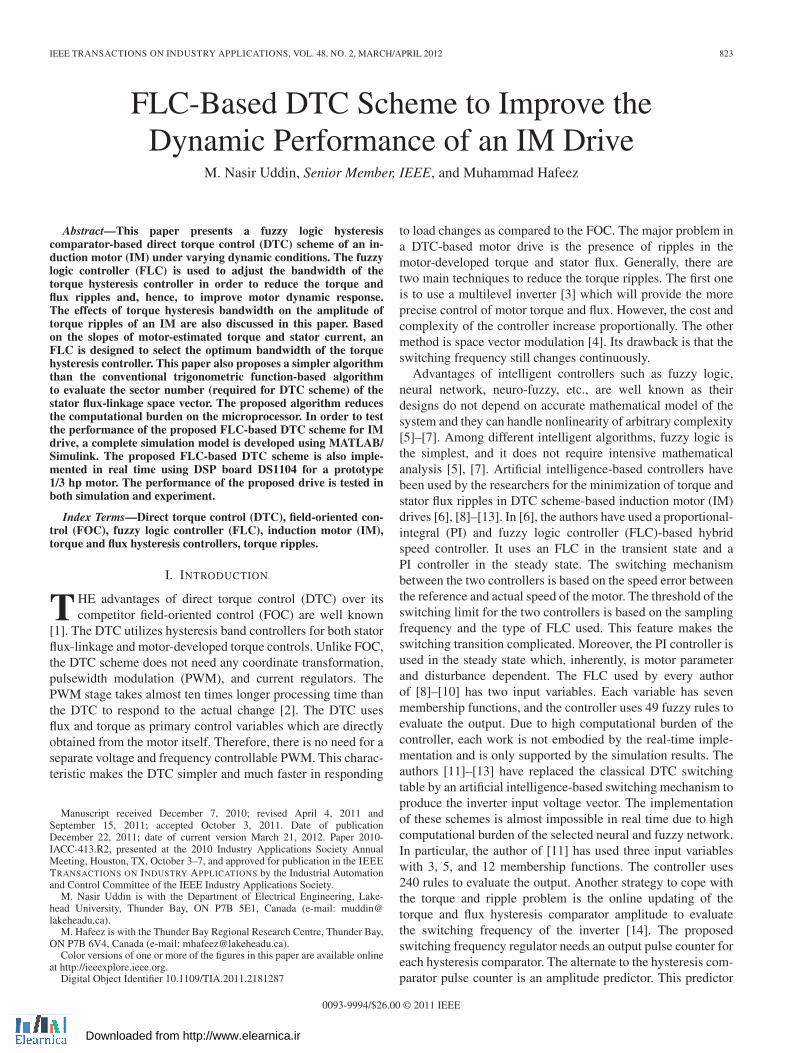
Fig. 1. Conventional DTC scheme for IM drive.
is highly motor parameter and speed dependent. There is no ex-act strategy or formula to get the command inverter frequency.Hence, there is no real-time implementation of the work.
Some researchers have tried to minimize the ripples, keepingthe constant switching frequency by evaluating the switchinginstant of the voltage vector to inverter [15], [16]. The authorshave derived a mathematical model for motor torque slope andtorque rms values. The relations are based on many assumptionsand are highly motor parameter dependent. The designed modelis not robust to motor parameters and load disturbances. Thepaper [15] does not have any real-time results. Reference [16]has some real-time results, but the implementation was notfully successful as they only provide the results at low-speedcondition. Moreover, there is no real-time result under varyingspeed or torque commands.
Therefore, in this paper, a simpler practically feasible FLC isdesigned that selects the appropriate bandwidth for the torquehysteresis controller to optimize the ripple level in the devel-oped torque and, hence, to improve the motor speed response.
Conventionally, the determination of the sector number of thestator flux-linkage space vector for the DTC scheme involvesa trigonometric function (tangent) [17]. The microprocessorevaluates the trigonometric function by using time-consumingcomplex calculations as compared to normal arithmetic rela-tions [18]. The requirement for the working of the DTC schemeis only the sector number, in which the stator flux-linkage spacevector is positioned and not its accurate position. Therefore,this paper presents a simpler efficient algorithm to determinethe stator flux-linkage sector without using any trigonometricor complex function. Hence, the proposed algorithm reducesthe calculation burden for the processor.
A complete simulation model for the proposed drive isdeveloped using MATLAB/Simulink. The proposed FLC-basedDTC scheme is implemented in real time using DSP boardDS1104 for a prototype 1/3 hp motor. The effectiveness ofthe proposed drive is verified at different dynamic operatingconditions by both simulation and experimental results.
II. MODELING OF IM FOR DTC
A. Stator Voltage and Flux
The block diagram for the conventional DTC scheme of anIM drive is shown in Fig. 1 [1], [19]. Based on the three inputs
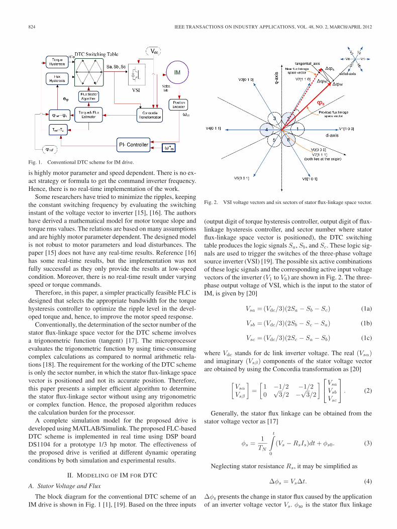
Fig. 2. VSI voltage vectors and six sectors of stator flux-linkage space vector.
(output digit of torque hysteresis controller, output digit of flux-linkage hysteresis controller, and sector number where statorflux-linkage space vector is positioned), the DTC switchingtable produces the logic signals Sa, Sb, and Sc. These logic sig-nals are used to trigger the switches of the three-phase voltagesource inverter (VSI) [19]. The possible six active combinationsof these logic signals and the corresponding active input voltagevectors of the inverter (V1 to V6) are shown in Fig. 2. The three-phase output voltage of VSI, which is the input to the stator ofIM, is given by [20]
Vsa = (Vdc/3)(2Sa − Sb − Sc) (1a)
Vsb = (Vdc/3)(2Sb − Sc − Sa) (1b)
Vsc = (Vdc/3)(2Sc − Sa − Sb) (1c)
where Vdc stands for dc link inverter voltage. The real (Vsα)and imaginary (Vsβ) components of the stator voltage vectorare obtained by using the Concordia transformation as [20]
[Vsα
Vsβ
]=
[1 −1/2 −1/20
√3/2 −√
3/2
] ⎡⎣Vsa
Vsb
Vsc
⎤⎦ . (2)
Generally, the stator flux linkage can be obtained from thestator voltage vector as [17]
φs =1
TN
t∫0
(Vs − RsIs)dt + φs0. (3)
Neglecting stator resistance Rs, it may be simplified as
Δφs = VsΔt. (4)
Δφs presents the change in stator flux caused by the applicationof an inverter voltage vector Vs. φso is the stator flux linkage
UDDIN AND HAFEEZ: FLC-BASED DTC SCHEME TO IMPROVE THE DYNAMIC PERFORMANCE OF AN IM DRIVE 825
at t = 0. The electromagnetic developed torque in IM is givenby [19]
Te = PLm
σLsLr|φs|∗|φr|∗ sin θsr (5)
where σ = 1 − (L2m/LsLr) is the leakage factor, P is the
number of pole pairs, Ls and Lr are the stator and the rotor self-inductances, respectively, and θsr is the angle between the stator(φs) and rotor (φr) flux-linkage space vectors. In the steadystate, |φr | and |φs | are almost constant, and Te depends on thetorque angle θsr.
Fig. 2 shows the change in stator flux linkage Δφs which iscaused by the application of new stator voltage vector V3. Thestator flux-linkage space vector “φs” before and after the appli-cation of vector V3 is shown by continuous and dotted vectors,respectively. From (4), it is clear that the change in stator fluxΔφs has the same direction of the applied voltage and its am-plitude is dependent on the stator input voltage vector and theduration “Δt” for which this vector is applied. Fig. 2 also showsthe radial component (Δφsr ) and tangential component (Δst)of Δφs . The radial component Δφsr , being in phase with φs ,causes a direct change in the amplitude of the stator flux-linkagespace vector. The tangential component Δφst , being orthogonalto φs , only changes the position of stator flux-linkage spacevector φs . Thus, Δφst indirectly controls the angle betweenthe stator and rotor flux-linkage space vectors, i.e., the torqueangle θsr, and hence, it controls the motor-developed torque(5). Therefore, Δφst is the torque-producing component ofΔφs . From Fig. 2, it can also be observed that, with respectto the current sector number of the stator flux-linkage spacevector, the application of a voltage vector from the forwarddirection/(direction of rotation)/(anticlockwise direction) byone or two sectors increases the torque-producing component ofΔφs and vice versa which is the case for the rotation in reversedirection. Similarly, the amplitude of the stator flux-linkagespace vector increases by the application of a voltage vectorfrom a sector which is one step forward/backward directionwith respect to its current sector number. For example, if,currently, the stator flux-linkage space vector is lying in sector2 and it is required to increase both the motor-developed torqueand stator flux linkage, then the inverter voltage vector V3
should be selected in the next sampling period. However, if itis required to decrease the torque but increase the flux, then theinverter voltage vector V1 should be selected in the next sam-pling period. Following this pattern, one can explain the logicbehind the selection of voltage vectors in the DTC switchingtable.
When a zero stator voltage vector (V0, V7) is applied, φs
stops while φr continues to move forward, reducing θsr aswell as Te. If the application of zero vectors is sufficientlylong enough so that φr overtakes the φs vector, then θsr be-comes negative. It will produce the retarding torque. Hence,the duration of application of any stator voltage vector playsan important role on the torque ripple. By cyclic switching ofactive and zero stator voltage vectors, we can control the motortorque with optimal level of the ripple. At low rotor speeds,the φr motion is too slow to achieve rapid torque reduction. In
such situation, instead of zero vectors, an active vector movingbackward is the preferred choice for effective torque control.This section elaborates the idea of voltage vector selection inthe DTC switching table.
B. Flux and Torque Hysteresis Controllers
For the DTC scheme, the motor-developed torque and statorflux linkage are estimated as [17]
Te =32P [φsαIsβ − φsβIsα] (6)
φs =√(
φ2sα + φ2
sβ
)(7)
where Isα and Isβ are the direct and quadrature components ofstator current, respectively. As shown in Fig. 1, these estimatedvalues of torque and flux are compared with the correspondingcommand/reference values, and the error signals are deliveredto the respective hysteresis controllers. On the basis of themagnitude of the error signals and allowable bandwidth, eachhysteresis controller produces a digit. Then, the position of thestator flux-linkage space vector is evaluated as
θs = tan−1(φsβ/φsα). (8)
Using this angle, the flux sector number (1 to 6) is determinedby using the flux sector algorithm [17]. Therefore, two digitsproduced by hysteresis controllers and one by flux positionare collectively used to trigger the switches of the VSI whichselects the appropriate voltage vector by using the classicalDTC lookup table [19]. Fig. 2 shows the possible voltage vec-tors which are employed in the DTC scheme. The appropriatevoltage vector in each sampling period is selected in such a waythat the torque and flux remain within their respective bandlimits.
C. Torque Ripple Analysis
Under the influence of any active VSI voltage vector, themotor torque keeps on increasing or decreasing until it touchesthe boundary defined by torque hysteresis bands. The torqueripple is only affected by the width of the torque hysteresis bandand is almost independent of the width of the flux hysteresisband [21]. Torque ripple changes proportionally with change inthe torque hysteresis bandwidth. However, due to the discretenature of the control system, there might be still torque rippleseven with the zero bandwidth of the hysteresis controller. Onthe other hand, if the bandwidth decreases, the VSI switchingfrequency increases, which proportionally increases its switch-ing losses. Consequently, the bandwidth of the torque hysteresiscontroller must be optimized in such as a way that the torqueripple level and switching frequency of the inverter are withinacceptable limits. A too small band may result in the selectionof reverse voltage vector instead of zero vector to reduce thetorque. The selection of reverse voltage vector may then causetorque undershoot. Hence, the torque ripple will become higherthan those specified by the hysteresis controller band limits. The
826 IEEE TRANSACTIONS ON INDUSTRY APPLICATIONS, VOL. 48, NO. 2, MARCH/APRIL 2012
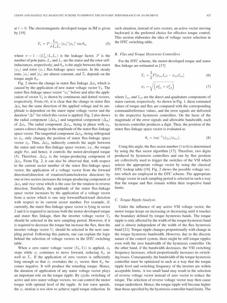
Fig. 3. Stator flux-linkage vector with six sectors. The stator flux-linkagevector with its coordinates is shown at the boundary of each sector.
torque slope is a function of motor speed, stator voltage andflux, and rotor flux vector and is given by [22]
slope+ = − Te(n)στsr
+3PLm
2σLsLr[(Vs − jωmφs).jφr] (9)
slope− = − Te(n)στsr
+3PLm
2σLsLr[(−jωmφs).jφr] (10)
where Te(n) is the nth sample of torque and ωm is the rotorspeed. Both of these equations are speed dependent, but at lowerspeed range, the positive slope is greater than the negative slope.It means that the time taken by torque to reach upper and lowerband limits, as well as switching frequency, varies with the rotorspeed.
III. PROPOSED FLUX-LINKAGE SECTOR ALGORITHM
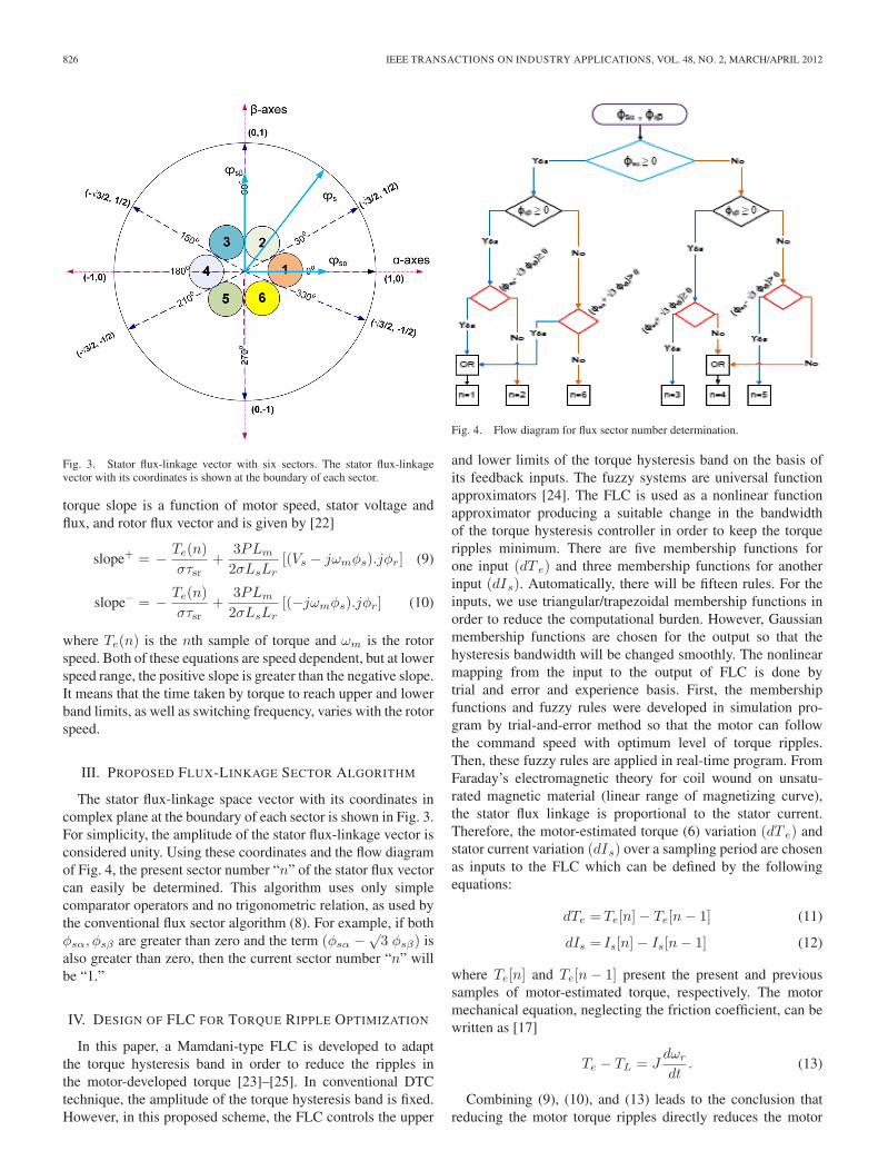
The stator flux-linkage space vector with its coordinates incomplex plane at the boundary of each sector is shown in Fig. 3.For simplicity, the amplitude of the stator flux-linkage vector isconsidered unity. Using these coordinates and the flow diagramof Fig. 4, the present sector number “n” of the stator flux vectorcan easily be determined. This algorithm uses only simplecomparator operators and no trigonometric relation, as used bythe conventional flux sector algorithm (8). For example, if bothφsα, φsβ are greater than zero and the term (φsα −√
3 φsβ) isalso greater than zero, then the current sector number “n” willbe “1.”
IV. DESIGN OF FLC FOR TORQUE RIPPLE OPTIMIZATION
In this paper, a Mamdani-type FLC is developed to adaptthe torque hysteresis band in order to reduce the ripples inthe motor-developed torque [23]–[25]. In conventional DTCtechnique, the amplitude of the torque hysteresis band is fixed.However, in this proposed scheme, the FLC controls the upper
Fig. 4. Flow diagram for flux sector number determination.
and lower limits of the torque hysteresis band on the basis ofits feedback inputs. The fuzzy systems are universal functionapproximators [24]. The FLC is used as a nonlinear functionapproximator producing a suitable change in the bandwidthof the torque hysteresis controller in order to keep the torqueripples minimum. There are five membership functions forone input (dT e) and three membership functions for anotherinput (dIs). Automatically, there will be fifteen rules. For theinputs, we use triangular/trapezoidal membership functions inorder to reduce the computational burden. However, Gaussianmembership functions are chosen for the output so that thehysteresis bandwidth will be changed smoothly. The nonlinearmapping from the input to the output of FLC is done bytrial and error and experience basis. First, the membershipfunctions and fuzzy rules were developed in simulation pro-gram by trial-and-error method so that the motor can followthe command speed with optimum level of torque ripples.Then, these fuzzy rules are applied in real-time program. FromFaraday’s electromagnetic theory for coil wound on unsatu-rated magnetic material (linear range of magnetizing curve),the stator flux linkage is proportional to the stator current.Therefore, the motor-estimated torque (6) variation (dT e) andstator current variation (dIs) over a sampling period are chosenas inputs to the FLC which can be defined by the followingequations:
dTe =Te[n] − Te[n − 1] (11)
dIs = Is[n] − Is[n − 1] (12)
where Te[n] and Te[n − 1] present the present and previoussamples of motor-estimated torque, respectively. The motormechanical equation, neglecting the friction coefficient, can bewritten as [17]
Te − TL = Jdωr
dt. (13)
Combining (9), (10), and (13) leads to the conclusion thatreducing the motor torque ripples directly reduces the motor
UDDIN AND HAFEEZ: FLC-BASED DTC SCHEME TO IMPROVE THE DYNAMIC PERFORMANCE OF AN IM DRIVE 827
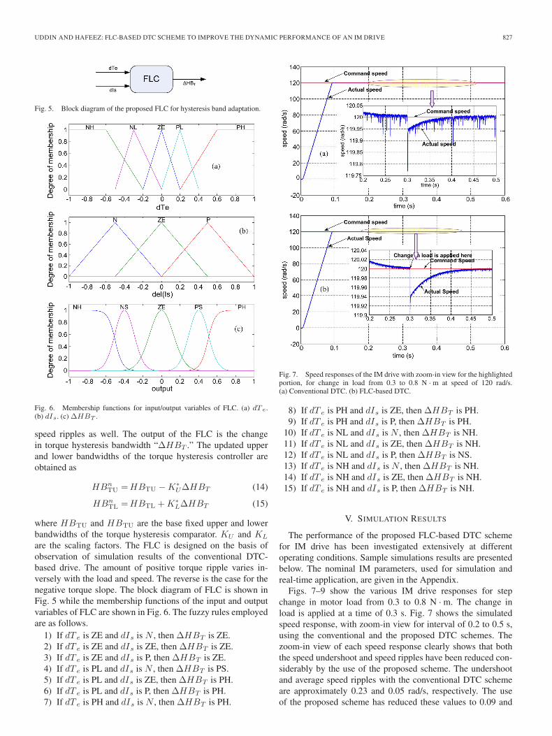
Fig. 5. Block diagram of the proposed FLC for hysteresis band adaptation.
Fig. 6. Membership functions for input/output variables of FLC. (a) dT e.(b) dIs. (c) ΔHBT .
speed ripples as well. The output of the FLC is the changein torque hysteresis bandwidth “ΔHBT .” The updated upperand lower bandwidths of the torque hysteresis controller areobtained as
HBnTU = HBTU − K∗
UΔHBT (14)
HBnTL = HBTL + K∗
LΔHBT (15)
where HBTU and HBTU are the base fixed upper and lowerbandwidths of the torque hysteresis comparator. KU and KL
are the scaling factors. The FLC is designed on the basis ofobservation of simulation results of the conventional DTC-based drive. The amount of positive torque ripple varies in-versely with the load and speed. The reverse is the case for thenegative torque slope. The block diagram of FLC is shown inFig. 5 while the membership functions of the input and outputvariables of FLC are shown in Fig. 6. The fuzzy rules employedare as follows.
1) If dT e is ZE and dIs is N , then ΔHBT is ZE.2) If dT e is ZE and dIs is ZE, then ΔHBT is ZE.3) If dT e is ZE and dIs is P, then ΔHBT is ZE.4) If dT e is PL and dIs is N , then ΔHBT is PS.5) If dT e is PL and dIs is ZE, then ΔHBT is PH.6) If dT e is PL and dIs is P, then ΔHBT is PH.7) If dT e is PH and dIs is N , then ΔHBT is PH.
Fig. 7. Speed responses of the IM drive with zoom-in view for the highlightedportion, for change in load from 0.3 to 0.8 N · m at speed of 120 rad/s.(a) Conventional DTC. (b) FLC-based DTC.
8) If dT e is PH and dIs is ZE, then ΔHBT is PH.9) If dT e is PH and dIs is P, then ΔHBT is PH.
10) If dT e is NL and dIs is N , then ΔHBT is NH.11) If dT e is NL and dIs is ZE, then ΔHBT is NH.12) If dT e is NL and dIs is P, then ΔHBT is NS.13) If dT e is NH and dIs is N , then ΔHBT is NH.14) If dT e is NH and dIs is ZE, then ΔHBT is NH.15) If dT e is NH and dIs is P, then ΔHBT is NH.
V. SIMULATION RESULTS
The performance of the proposed FLC-based DTC schemefor IM drive has been investigated extensively at differentoperating conditions. Sample simulations results are presentedbelow. The nominal IM parameters, used for simulation andreal-time application, are given in the Appendix.
Figs. 7–9 show the various IM drive responses for stepchange in motor load from 0.3 to 0.8 N · m. The change inload is applied at a time of 0.3 s. Fig. 7 shows the simulatedspeed response, with zoom-in view for interval of 0.2 to 0.5 s,using the conventional and the proposed DTC schemes. Thezoom-in view of each speed response clearly shows that boththe speed undershoot and speed ripples have been reduced con-siderably by the use of the proposed scheme. The undershootand average speed ripples with the conventional DTC schemeare approximately 0.23 and 0.05 rad/s, respectively. The useof the proposed scheme has reduced these values to 0.09 and
828 IEEE TRANSACTIONS ON INDUSTRY APPLICATIONS, VOL. 48, NO. 2, MARCH/APRIL 2012
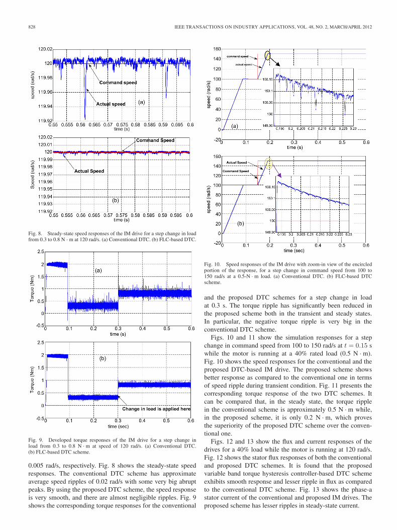
Fig. 8. Steady-state speed responses of the IM drive for a step change in loadfrom 0.3 to 0.8 N · m at 120 rad/s. (a) Conventional DTC. (b) FLC-based DTC.
Fig. 9. Developed torque responses of the IM drive for a step change inload from 0.3 to 0.8 N · m at speed of 120 rad/s. (a) Conventional DTC.(b) FLC-based DTC scheme.
0.005 rad/s, respectively. Fig. 8 shows the steady-state speedresponses. The conventional DTC scheme has approximateaverage speed ripples of 0.02 rad/s with some very big abruptpeaks. By using the proposed DTC scheme, the speed responseis very smooth, and there are almost negligible ripples. Fig. 9shows the corresponding torque responses for the conventional
Fig. 10. Speed responses of the IM drive with zoom-in view of the encircledportion of the response, for a step change in command speed from 100 to150 rad/s at a 0.5-N · m load. (a) Conventional DTC. (b) FLC-based DTCscheme.
and the proposed DTC schemes for a step change in loadat 0.3 s. The torque ripple has significantly been reduced inthe proposed scheme both in the transient and steady states.In particular, the negative torque ripple is very big in theconventional DTC scheme.
Figs. 10 and 11 show the simulation responses for a stepchange in command speed from 100 to 150 rad/s at t = 0.15 swhile the motor is running at a 40% rated load (0.5 N · m).Fig. 10 shows the speed responses for the conventional and theproposed DTC-based IM drive. The proposed scheme showsbetter response as compared to the conventional one in termsof speed ripple during transient condition. Fig. 11 presents thecorresponding torque response of the two DTC schemes. Itcan be compared that, in the steady state, the torque ripplein the conventional scheme is approximately 0.5 N · m while,in the proposed scheme, it is only 0.2 N · m, which provesthe superiority of the proposed DTC scheme over the conven-tional one.
Figs. 12 and 13 show the flux and current responses of thedrives for a 40% load while the motor is running at 120 rad/s.Fig. 12 shows the stator flux responses of both the conventionaland proposed DTC schemes. It is found that the proposedvariable band torque hysteresis controller-based DTC schemeexhibits smooth response and lesser ripple in flux as comparedto the conventional DTC scheme. Fig. 13 shows the phase-astator current of the conventional and proposed IM drives. Theproposed scheme has lesser ripples in steady-state current.
UDDIN AND HAFEEZ: FLC-BASED DTC SCHEME TO IMPROVE THE DYNAMIC PERFORMANCE OF AN IM DRIVE 829
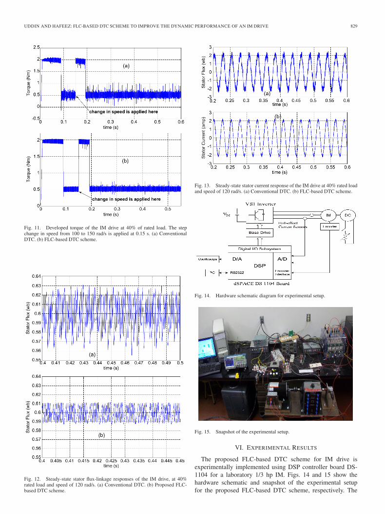
Fig. 11. Developed torque of the IM drive at 40% of rated load. The stepchange in speed from 100 to 150 rad/s is applied at 0.15 s. (a) ConventionalDTC. (b) FLC-based DTC scheme.
Fig. 12. Steady-state stator flux-linkage responses of the IM drive, at 40%rated load and speed of 120 rad/s. (a) Conventional DTC. (b) Proposed FLC-based DTC scheme.
Fig. 13. Steady-state stator current response of the IM drive at 40% rated loadand speed of 120 rad/s. (a) Conventional DTC. (b) FLC-based DTC scheme.
Fig. 14. Hardware schematic diagram for experimental setup.
Fig. 15. Snapshot of the experimental setup.
VI. EXPERIMENTAL RESULTS
The proposed FLC-based DTC scheme for IM drive isexperimentally implemented using DSP controller board DS-1104 for a laboratory 1/3 hp IM. Figs. 14 and 15 show thehardware schematic and snapshot of the experimental setupfor the proposed FLC-based DTC scheme, respectively. The
830 IEEE TRANSACTIONS ON INDUSTRY APPLICATIONS, VOL. 48, NO. 2, MARCH/APRIL 2012
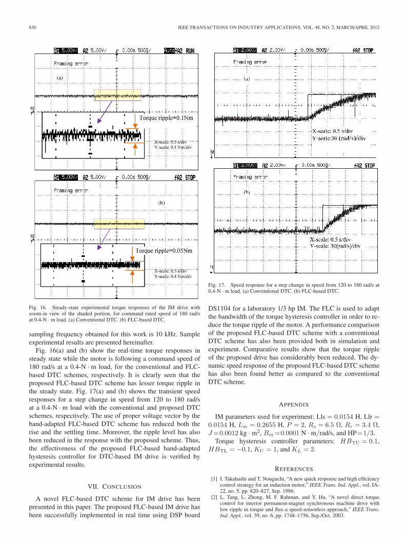
Fig. 16. Steady-state experimental torque responses of the IM drive withzoom-in view of the shaded portion, for command rated speed of 180 rad/sat 0.4-N · m load. (a) Conventional DTC. (b) FLC-based DTC.
sampling frequency obtained for this work is 10 kHz. Sampleexperimental results are presented hereinafter.
Fig. 16(a) and (b) show the real-time torque responses insteady state while the motor is following a command speed of180 rad/s at a 0.4-N · m load, for the conventional and FLC-based DTC schemes, respectively. It is clearly seen that theproposed FLC-based DTC scheme has lesser torque ripple inthe steady state. Fig. 17(a) and (b) shows the transient speedresponses for a step change in speed from 120 to 180 rad/sat a 0.4-N · m load with the conventional and proposed DTCschemes, respectively. The use of proper voltage vector by theband-adapted FLC-based DTC scheme has reduced both therise and the settling time. Moreover, the ripple level has alsobeen reduced in the response with the proposed scheme. Thus,the effectiveness of the proposed FLC-based band-adaptedhysteresis controller for DTC-based IM drive is verified byexperimental results.
VII. CONCLUSION
A novel FLC-based DTC scheme for IM drive has beenpresented in this paper. The proposed FLC-based IM drive hasbeen successfully implemented in real time using DSP board
Fig. 17. Speed response for a step change in speed from 120 to 180 rad/s at0.4-N · m load. (a) Conventional DTC. (b) FLC-based DTC.
DS1104 for a laboratory 1/3 hp IM. The FLC is used to adaptthe bandwidth of the torque hysteresis controller in order to re-duce the torque ripple of the motor. A performance comparisonof the proposed FLC-based DTC scheme with a conventionalDTC scheme has also been provided both in simulation andexperiment. Comparative results show that the torque rippleof the proposed drive has considerably been reduced. The dy-namic speed response of the proposed FLC-based DTC schemehas also been found better as compared to the conventionalDTC scheme.
APPENDIX
IM parameters used for experiment: Lls = 0.0154 H, Llr =0.0154 H, Lm = 0.2655 H, P = 2, Rs = 6.5 Ω, Rr = 3.4 Ω,J =0.0012 kg · m2, Bm =0.0001 N · m/rad/s, and HP=1/3.
Torque hysteresis controller parameters: HBTU = 0.1,HBTL = −0.1, KU = 1, and KL = 2.
REFERENCES
[1] I. Takahashi and T. Nouguchi, “A new quick response and high efficiencycontrol strategy for an induction motor,” IEEE Trans. Ind. Appl., vol. IA-22, no. 5, pp. 820–827, Sep. 1986.
[2] L. Tang, L. Zhong, M. F. Rahman, and Y. Hu, “A novel direct torquecontrol for interior permanent-magnet synchronous machine drive withlow ripple in torque and flux-a speed-sensorless approach,” IEEE Trans.Ind. Appl., vol. 39, no. 6, pp. 1748–1756, Sep./Oct. 2003.
UDDIN AND HAFEEZ: FLC-BASED DTC SCHEME TO IMPROVE THE DYNAMIC PERFORMANCE OF AN IM DRIVE 831
[3] S. Kouro, R. Bernal, H. Miranda, C. A. Silva, and J. Rodriguez, “High-performance torque and flux control for multilevel inverter fed inductionmotors,” IEEE Trans. Power Electron., vol. 22, no. 6, pp. 2116–2123,Nov. 2007.
[4] D. Casadei and T. Angelo, “Implementation of a direct torque control al-gorithm for induction motors based on discrete space vector modulation,”IEEE Trans. Power Electron., vol. 15, no. 4, pp. 769–777, July 2000.
[5] C.-T. Lin and C. S. G. Lee, Neural Fuzzy Systems: A Neuro-Fuzzy Syn-ergism to Intelligent Systems. Upper Saddle River, NJ: Prentice-Hall,1996.
[6] Y.-S. Lai and J.-C. Lin, “New hybrid fuzzy controller for direct torquecontrol induction motor drives,” IEEE Trans. Power Electron., vol. 18,no. 5, pp. 1211–1219, Sep. 2003.
[7] L. Youb and A. Craciunescu, “Direct torque control of induction motorswith fuzzy minimization torque ripple,” in Proc. WESCO, 2009, vol. 2,pp. 713–717.
[8] A. F. Aimer, A. Bendiabdellah, A. Miloudi, and C. Mokhtar, “Applica-tion of fuzzy logic for a ripple reduction strategy in DTC scheme of aPWM inverter fed induction motor drives,” J. Elect. Syst., Special Issue 1,pp. 13–17, Nov. 2009.
[9] G. Sheng-wei and C. Yan, “Research on torque ripple minimization strat-egy for direct torque control of induction motors,” in Proc. ICCASM,2010, pp. VI-278–VI-281.
[10] G. M. Gadoue, D. Giaouris, and J. W. Finch, “Artificial intelligence-basedspeed control of DTC induction motor drives—A comparative study,”Elect. Power Syst. Res., vol. 79, no. 1, pp. 210–219, 2009.
[11] R. Toufouti, S. Meziane, and H. Benalla, “Direct torque control for in-duction motor using fuzzy logic,” ACSE J., vol. 6, no. 2, pp. 19–26,Jun. 2006.
[12] F. Sheidaei, M. Sedighizadeh, S. H. Mohseni-Zonoozi, andY. Alinejad-Beromi, “A fuzzy logic direct torque control for inductionmotor sensorless drive,” in Proc. UPEC, 2007, pp. 197–202.
[13] Y. V. S. Reddy, M. Vijayakumar, and T. Brahmananda Reddy, “Directtorque control of induction motor using sophisticated lookup tables basedon neural networks,” AIML J., vol. 7, no. 1, pp. 9–15, Jun 2007.
[14] J.-K. Kang, D.-W. Chung, and S.-K. Sul, “Direct torque control of induc-tion machine with variable amplitude control of flux and torque hysteresisbands,” in Proc. IEMD, 1999, pp. 640–642.
[15] K.-K. La, M.-H. Shin, and D.-S. Hyun, “Direct torque control of induc-tion motor with reduction of torque ripple,” in Proc. IEEE IECON, 2000,pp. 1087–1092.
[16] J.-K. Kang and S.-K. Sul, “New direct torque control of induction mo-tor for minimum torque ripple and constant switching frequency,” IEEETrans. Ind. Appl., vol. 35, no. 5, pp. 1076–1082, Sep./Oct. 1999.
[17] P. Vas, Sensorless Vector and Direct Torque Control. London, U.K.:Oxford Univ. Press, 1998.
[18] A. E. Fowkes, “Hardware efficient algorithm for trigonometric functions,”IEEE Trans. Comput., vol. 42, no. 2, pp. 235–239, Feb. 1993.
[19] H. F. Abdul Wahab and H. Sanusi, “Simulink model of direct torquecontrol of induction machine,” Amer. J. Appl. Sci., vol. 5, no. 8, pp. 1083–1090, 2008.
[20] A. M. Trzynadlowshi, The Field Orientation Principle in Control ofInduction Motors. Norwell, MA: Kluwer, 1994.
[21] D. Casadei, G. Grandi, G. Serra, and A. Tani, “Effects of flux and torquehysteresis band amplitude in direct torque control of induction machines,”in Proc. IEEE IECON, 1994, vol. 1, pp. 299–304.
[22] N. Rumzi, N. Idris, and A. H. M. Yatim, “Direct torque control of induc-tion motors with constant switching frequency and reduced torque ripple,”IEEE Trans. Ind. Electron., vol. 51, no. 4, pp. 758–767, Aug. 2004.
[23] P. Vas, Artificial-Intelligence-Based Electrical Machines and Drives.New York: Oxford Univ. Press, 1999.
[24] C. C. Lee, “Fuzzy logic in control systems: Fuzzy logic controller—Part I,” IEEE Trans. Syst., Man, Cybern., vol. 20, no. 2, pp. 404–418,Mar./Apr. 1990.
[25] K. M. Passino and S. Yurkovich, Fuzzy Control. Menlo Park, CA:Addison-Wesley Longman, 1998, p. 72.
M. Nasir Uddin (S’98–M’00–SM’04) receivedthe B.Sc. and M.Sc. degrees in electrical andelectronic engineering from Bangladesh Universityof Engineering and Technology (BUET), Dhaka,Bangladesh, in 1993 and 1996, respectively, and thePh.D. degree in electrical engineering from Memor-ial University of Newfoundland (MUN), St. John’s,NL, Canada, in 2000.
He is currently a Professor in the Department ofElectrical Engineering, Lakehead University (LU),Thunder Bay, ON, Canada. He was a Visiting Pro-
fessor (June–December 2011) at the University of Malaya, Kuala Lumpur,Malaysia, during his sabbatical leave from Lakehead. Previously, he served asan International Visiting Professor (June–July 2010) at Tokyo University of Sci-ence, Suwa, Japan, and a Visiting Associate Professor (July–December 2006)at North South University, Dhaka. Previously, he was an Assistant Professor inthe Department of Electrical and Computer Engineering, University of SouthAlabama, Mobile, from January 2001 to May 2001, a Postdoctoral Fellow atMUN from May 2001 to August 2001, and an Assistant Professor from 1996to 1997 and a Lecturer from 1994 to 1996 at BUET. He also served as anInstructor from 1999 to 2000 at the College of the North Atlantic, St. John’s,Canada. He possesses more than 15 years of teaching experience and hasauthored or coauthored over 120 papers in international journals and conferenceproceedings. His research interests include power electronics, electric motordrives, and the application of intelligent controllers.
Dr. Uddin is a Registered Professional Engineer in the Province of Ontario,Canada. Currently, he is serving as Chair of the IEEE Industry ApplicationsSociety (IAS) Industrial Automation and Control Committee (IACC). He is theTechnical Chair for the IEEE IAS (IACC) Annual Meetings 2011 and 2012.Previously, he was the TRANSACTIONS Review Chair for IEEE/IAS/IACC.Recently, he was bestowed upon with the prestigious Lakehead UniversityDistinguished Researcher Award 2010. He is the recipient of two FirstPrize and one Third Prize Paper Awards from the IEEE/IAS/IACC and both2004 Contributions to Research Award and Contributions to Teaching Awardfrom LU.
Muhammad Hafeez received the B.Sc. degree inelectrical engineering from the University of Engi-neering and Technology, Lahore, Pakistan, in 1992,and the M.Sc. degree in control engineering fromLakehead University, Thunder Bay, ON, Canada,in 2010.
He served as an Electrical Engineer for the Wa-ter and Power Development Authority, Pakistan(May 1992–February 2002). He possesses morethan nine years of experience in maintenance, trou-bleshooting, and commissioning of electrical power
generating stations. He is currently with the Thunder Bay Regional ResearchCentre, Thunder Bay. His research interests include electric motor drives andthe application of intelligent controllers.