Embed Size (px)
Citation preview
SCC Highway Design Guidance - SEF version for checking
FOR LIFE
WWW.SOMERSET.GOV.UK
Page 2 of 90
RSA
Page 3 of 90
Contents
1 INTRODUCTION 4
1.1 EXPLANATIONS AND DEFINITIONS 4 1.2 APPROACH 6 1.3 AIMS 7 1.4 ADVANCE PAYMENTS CODE AND SECTION 38 CONSIDERATIONS 9 1.5 PUBLIC RIGHTS OF WAY 11
2 GENERAL DESIGN PARAMETERS 12
2.1 ESTATE ROAD HIERARCHY 12 2.2 SAFETY AND SECURITY 19 2.3 ACCESS FOR THE DISABLED 21 2.4 EMERGENCY SERVICES 23 2.5 OTHER SERVICES 24 2.6 TRAFFIC CALMING MEASURES 25 2.7 PEDESTRIAN MOVEMENT 27 2.8 CYCLING PROVISION 27 2.9 PUBLIC TRANSPORT 27 2.10 STATUTORY SERVICES 27
3 DESIGN DETAILS 27
3.1 TYPE 1 (III) LOCAL DISTRIBUTOR ROAD 27 3.2 TYPE 2 – TRANSITIONAL ROAD 27 3.3 TYPE 3 – COLLECTOR ROAD 27 3.4 TYPE 4 (I) 27 3.5 TYPE 5 – SHARED SURFACES 27 3.6 TYPE 6 – FOOTPATHS 27 3.7 TYPE 7 – CYCLEWAYS 27 3.8 TYPE 8 – PRIVATE DRIVES 27 3.9 VISIBILITY AT JUNCTIONS 27 3.10 VISIBILITY AT BENDS 27 3.11 JUNCTION LAYOUT DETAILS 27 3.12 VERTICAL ALIGNMENT 27 3.13 SPEED CONTROL BENDS 27 3.14 SURFACE WATER DRAINAGE 27 3.15 TURNING MANOEUVRES 27 3.16 STREET LIGHTING 27
4 OTHER DESIGN FEATURES 27
4.1 CAR PARKING 27 4.2 LANDSCAPING 27 4.3 RETENTION OF EXISTING TREES AND HEDGES 27 4.4 NEW PLANTING 27 4.5 STRUCTURES ABUTTING OR OVER THE HIGHWAY 27 4.6 TRAFFIC SIGNS, ROAD MARKINGS AND STREET FURNITURE 27
5 CARRIAGEWAY 27
5.1 GENERAL CONSIDERATIONS 27 5.2 ROAD PAVEMENT DESIGN 27

Page 4 of 90
1 INTRODUCTION
1.1 EXPLANATIONS AND DEFINITIONS
1.1.1. Somerset County Council as Highway Authority has overall responsibility for the
maintenance of public highways within the County, with the exception of Trunk Roads and Motorways which are maintained under an Agency Agreement with the Department for Transport by the Highways Agency.
1.1.2. Somerset has given help and guidance to developers, architects and consulting
engineers in the form of an estate road booklet for over twenty-seven years. The most recent ‘orange booklet’ was produced in 1980, revised in 1983 and introduced concepts which were outlined in Design Bulletin 32 produced by the Department of the Environment and Transport.
1.1.3. Many of the aspirations contained in the general introduction of that document equally apply today. In the light of experience, however, and to take into account new initiatives on road safety, traffic calming, and the draft second edition of Design Bulletin 32, some modern-day considerations have been introduced.
1.1.4. This current design guide sets out to assist in creating visually attractive, safe,
convenient, nuisance-free and secure surroundings in which people may live. It contains general and certain specific design considerations to achieve this, together with the technical information to ensure that the necessary roads are suitable for adoption as County Highway.
1.1.5. The design guide is not intended to be a guide to development but rather a guide to the
highway elements where the development involves the construction of estate roads. However, no guide can, nor indeed should, cover all situations but should be flexible with certain basic constraints thus avoiding repetitive layouts.
1.1.6. It should be noted that this guide is not intended to deal with Primary and District
Distributor Roads, on which specific advice will be given by the Highway Authority. It is applicable to the layout of all housing and industrial estate roads for adoption and associated off-site highway works.
1.1.7. Procedural Details, expanding those shown in Appendix B and construction
requirements are covered in the sister document “Estate Roads in Somerset – Specification” (the green book) referred to as the Specification throughout this guide.

Page 5 of 90
Additionally, the following apply:-
Amenity footpaths - pedestrian routes serving mainly public open space not usually adopted by the Highway Authority but may be taken over by the District Council. Authority - means the Somerset County Council or one of the three District Councils incorporating the Excepted Areas or the appropriate region of the National Rivers Authority in respect of surface water drainage outfalls. Carriageway - those parts of residential roads which are intended for vehicular use only. Developer - means any company, firm or body or individual carrying out the development and should include their agents and contractors. Engineer - refers to the Director for the Environment or his authorised representative or within each Excepted Area, the Technical Officer (see Appendix A) Excepted Areas - these are the urban areas of Bridgwater, Taunton and Yeovil within which agency arrangements exist for the adoption of new estate roads. Footpaths - pedestrian routes divorced from, but usually linking, other areas of highway. Footways - intended solely for pedestrian use, usually adjoining and generally parallel to a kerbed carriageway, but alongside heavily trafficked roads a verge should be provided between footway and carriageway. Section 38 Agreement - refers to the Model Section 38 Agreement first published in May 1988. Sewers for Adoption - the current design and construction guide for developers published by the Water Authorities Association. Shared Surfaces - intended for use of both vehicular and pedestrian traffic. Specification - means the sister booklet entitled “Estate Roads in Somerset – Specification”.

Page 6 of 90
Statutory Undertaker - means a Statutory Undertaker as defined in Section 329(1) of the Highways Act 1980 and Mercury/British Telecommunications PLC.
1.2 APPROACH
1.1.1 In recent years there has been growing dissatisfaction with the design and layout of some housing developments and it is apparent that this is a national, if not international problem. Additionally, people are much more aware of the general environment, their local environment and conditions under which they wish to live.
Many factors contribute to uninteresting schemes, repetitive house design, choice of building materials and unimaginative layouts. Although the historic towns and villages within Somerset derive their character from circumstances quite different from the present, it is still possible today to create layouts and designs which are both pleasant to live in and visually attractive.
Page 7 of 90
1.3 AIMS
1.3.1 The designer will consider many elements in a corporate approach to any development proposal which strikes a balance between housing, planning and highway objectives. The designer will respond to the individual characteristics of a particular site to achieve a visually satisfying layout whilst accommodating the vehicular, pedestrian and servicing needs, amongst others. These various elements are covered in more detail later but should not be considered individually. Each can have an effect or influence on one or more of the others to a greater or lesser degree.
1.3.2 Within an estate some roads will be busier than others and the designer is urged to avoid placing homes with direct accesses along the more intensively trafficked roads. The basic concept should be to achieve layouts which lead people into an estate on a hierarchical road basis down to the smaller groups of housing.
1.3.3 Within Conservation Areas or where there is a strong visual appeal, as exists in a large number of towns and villages within Somerset, infill developments do pose different highway and design problems. A satisfactory solution should be achievable, however, setting the servicing and vehicular requirements against the effect it has on the existing street scene.
1.3.4 Good detailing and use of appropriate materials within a design cannot be stressed too strongly. Roads and footpaths are an integral part of the residential environment. The appropriate use of materials within the highway, as well as for the treatment of areas beyond highway limits, is of considerable importance.
The use of block paviors is encouraged particularly within shared surfaces. Both visually and from a road safety aspect the use of paviors help to inform drivers that the carriageway is used by both vehicles and pedestrians. A different surface material is considered essential within shared surfaces but a suitable alternative to paviors may be acceptable.
1.3.5 Whilst the design criteria set out in this guide are a minimum a flexible approach will be adopted in the application of these standards. Experimentation in design layout is encouraged and some relaxation of design standards will be considered to meet special site problems. Road safety, however, will always be of prime importance.
1.3.6 The designer should take account of the following considerations:
I. The characteristics of the site such as its shape, size, topography and existing
natural features, trees and hedges together with the landscape character of its surroundings.
II. In urban or village settings the characteristics of the surrounding spaces, buildings
and the materials with which they are constructed must be considered. III. The function of the surrounding roads based on the volumes, types and destinations
of vehicular traffic using them. Minimising the danger and nuisance which can be

Page 8 of 90
created by non-access traffic. Keeping vehicle flows and speeds low in the vicinity of homes.
IV. The volume and type of vehicular and pedestrian traffic likely to be generated by the
scheme itself. The location of existing and proposed community facilities such as shops, schools, parks and playgrounds and the routes that are likely to be taken by pedestrians, especially disabled and visually impaired people to reach them, and to provide safe and convenient surroundings for that movement of pedestrians. The possibility of encouraging pedestrian movement towards existing crossings and away from known hazards to safety (to walk alongside a roadway is not always the most pleasant solution but people generally wish to walk the most convenient, direct and safe route).
V. To minimise the danger to pedestrians and the inconvenience to emergency and
other services which can be caused by indiscriminate on-street parking; to create safe routes for vehicular movement.
VI. The location of any existing or proposed cycle routes and any need to make
connections with or to extend them.
VII. The location of public transport routes and bus stops. The requirements of local bus operators and any need to make provision for buses within the layout.
VIII. The needs for statutory and other services to be met efficiently including above-
ground equipment such as telephone kiosks and sub-stations. IX. The requirements of the fire and ambulance services and the police. X. The possibility of the use of structural landscaping as a means of helping to create
and define the form of the development and of integrating it into its setting. The use of a Landscape Architect at the design stage is encouraged.
XI. Minimising the risks of crime and vandalism.
1.3.7 All these principles are encompassed in this document which has been prepared jointly with the Local Planning Authorities. Within the above aims and the estate road types given later, it should be possible for the designer to create an interesting and imaginative layout giving a quality environment in which people can live.
1.3.8 In order to balance the aims of the Local Planning Authorities with those set out in this
booklet it is essential that early consultation takes place between the designer, the Local Planning Authority and the Engineer.

Page 9 of 90
1.4 ADVANCE PAYMENTS CODE AND SECTION 38 CONSIDERATIONS
1.4.1 Under Part XI of the Highways Act 1980, the Advance Payment Code (APC) requires that anyone proposing to build houses served by a private street must deposit enough money with the Highway Authority to cover the eventual cost of making up the street to adoption standard. This aims to relieve house buyers fronting streets of road charge liabilities under the Private Street Works Code if the developer defaults.
1.4.2 The Advance Payments Code was adoptive and it was adopted by Somerset County Council in 1967 and is in force throughout the County. Once adopted by an Authority the Code applies in all cases, there is no discretion to disapply it, irrespective of the number of dwellings which are proposed.
1.4.3 The Highways Act 1980 provides:
“219(1) Subject to the provisions of this section, where - a. it is proposed to erect a building for which plans are required to be deposited with
the local authority in accordance with the building regulations, and b. the building will have a frontage on a private street in which the street works
authority have power under the private street works code to require works to be executed or to execute the works,
no work shall be done in or for the purposes of erecting the building unless the owner of the land on which it is to be erected or a previous owner thereof has paid to the street works authority, or secured to the satisfaction of that authority the payment to them of such a sum as may be required under Section 220 below in respect of the cost of the street works in that street.
1.4.4 The County Council will serve the appropriate Notice setting out the sum required under
Section 220 within six weeks of Building Regulation Approval being granted. It is an offence to do work in contravention of the Code, that is to start building the houses before depositing the funds.
1.4.5 Where it is proposed to erect ‘low-cost dwellings or special needs housing’ in rural
areas the County Council is prepared to exempt from the Advance Payments Code any proposed building having a frontage to a private street providing:- i that the design and layout of the proposed private street, and of any means of
restricting access to it, are acceptable from the point of view of public safety, and ii after consultation with the County Council Secretary and Solicitor, that satisfactory
and enforceable long term arrangements have been made for securing the future maintenance of the private street.

Page 10 of 90
Early discussion with the Engineer is essential in these cases.
1.4.6 There are certain exemptions to the operation of the Advance Payments Code, however, one of which is an Agreement under Section 38 of the Highways Act. The Highway Authority encourages developers to enter into an Agreement under this section as an alternative to the deposit of money required by section 219. Such an Agreement will be based on approved plans and construction details to the satisfaction of the Highway Authority and be supported by a Bond to cover the due performance of the works. The information required to enable the necessary early procedures to be put in hand by the Highway Authority is set out in Appendix B.
1.4.7 Industrial estate roads – the Advance Payments Code does not apply to roads constructed in connection with Industrial Developments of Business Parks. The Highway Authority, if requested, is prepared to consider the adoption of such roads, using the Section 38 Agreement procedure, providing their design and construction meets with the criteria set out within this Design Guide and the associated Specification.

Page 11 of 90
1.5 PUBLIC RIGHTS OF WAY
1.5.1 The granting of planning permission does not itself constitute authority for any
interference by a developer with a public path. Before a path can be legally diverted or extinguished the Local Authority must agree to make an Order (see 5.3.).
1.5.2 Until an Order has been confirmed and brought into operation the legal line of a public
path remains unaltered. As it is a criminal offence (Section 137 of the Highways Act 1980) to obstruct the free passage along any highway (including public paths) without lawful authority or excuse, any development works or building materials on the line of a path will render the developer liable to prosecution. If a house is built over a path it is very unlikely that the property will sell, especially as nobody will give a mortgage on it.
1.5.3 It is recommended that the developers take the following steps:-
i check for the existence of public paths. The definitive map is the conclusive record
of public paths and it can be inspected at Local Authority offices. ii Take public paths into account in the design. It is far better it a development can
be designed so that an existing path is incorporated as a path and not simply as part of the estate roads. This need not be on its existing route. There may be features of the layout such as open spaces, small wooded areas or water through or around which a new path can be routed.
iii Consult the users. Liaison with local ramblers, parish, town or community councils
could save time and money at later stages. iv Allow time for the formal processing of Orders. An unopposed Diversion Order can
take six months to complete; one that is opposed can take eighteen months to two years to process. Apply for Diversion or Stopping-Up Orders in plenty of time.
v Signpost the new routes. After the legal formalities have been processed and the
new path completed, bear in mind that the users may not be familiar with the new route of the path. A few signposts at key points can be very helpful.
Page 12 of 90
2 GENERAL DESIGN PARAMETERS
2.1 ESTATE ROAD HIERARCHY
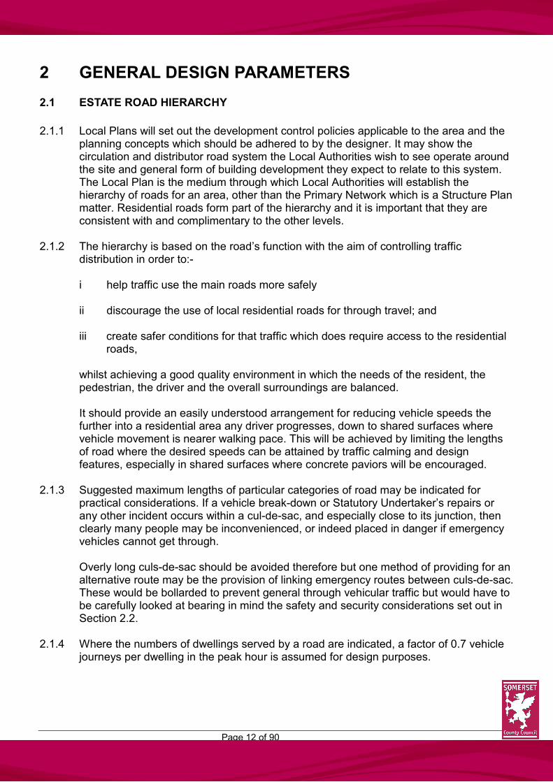
2.1.1 Local Plans will set out the development control policies applicable to the area and the
planning concepts which should be adhered to by the designer. It may show the circulation and distributor road system the Local Authorities wish to see operate around the site and general form of building development they expect to relate to this system. The Local Plan is the medium through which Local Authorities will establish the hierarchy of roads for an area, other than the Primary Network which is a Structure Plan matter. Residential roads form part of the hierarchy and it is important that they are consistent with and complimentary to the other levels.
2.1.2 The hierarchy is based on the road’s function with the aim of controlling traffic
distribution in order to:- i help traffic use the main roads more safely ii discourage the use of local residential roads for through travel; and iii create safer conditions for that traffic which does require access to the residential
roads, whilst achieving a good quality environment in which the needs of the resident, the pedestrian, the driver and the overall surroundings are balanced. It should provide an easily understood arrangement for reducing vehicle speeds the further into a residential area any driver progresses, down to shared surfaces where vehicle movement is nearer walking pace. This will be achieved by limiting the lengths of road where the desired speeds can be attained by traffic calming and design features, especially in shared surfaces where concrete paviors will be encouraged.
2.1.3 Suggested maximum lengths of particular categories of road may be indicated for practical considerations. If a vehicle break-down or Statutory Undertaker’s repairs or any other incident occurs within a cul-de-sac, and especially close to its junction, then clearly many people may be inconvenienced, or indeed placed in danger if emergency vehicles cannot get through. Overly long culs-de-sac should be avoided therefore but one method of providing for an alternative route may be the provision of linking emergency routes between culs-de-sac. These would be bollarded to prevent general through vehicular traffic but would have to be carefully looked at bearing in mind the safety and security considerations set out in Section 2.2.
2.1.4 Where the numbers of dwellings served by a road are indicated, a factor of 0.7 vehicle journeys per dwelling in the peak hour is assumed for design purposes.
Page 13 of 90
ROAD HIERARCHY: DIAGRAMMATIC ONLY

Page 14 of 90
2.1.5 DISTRIBUTOR ROADS – TYPE 1
Distributor Roads will usually be indicated, in broad lines, on Structure and/or Local Plans. The alignment will be laid down by the Planning and Highway Authorities even when built as part of an estate development. Distributor Roads fall under three headings:- (i) PRIMARY – necessary where the Distributor Road is accessed directly from or
replaces a section of a National Route as defined in the Structure Plan. (ii) DISTRICT – necessary where the Distributor Road links into the existing County
Route Hierarchy as defined in the Structure Plan.
(iii) LOCAL – necessary to distribute traffic within a residential area where the number of homes to be served would exceed 400. They will form the link between Primary/District Distributors and residential roads and will not give direct access to individual dwellings.
2.1.6 TRANISTIONAL ROADS – TYPE 2
These are short lengths of road linking Collector Roads to Local Distributor Roads and serving not more than 300 dwellings. Transitional Roads will have a minimum length of 30m, in order to be effective and adequately accommodate vehicles and will form the stem of a ‘T’ junction with other roads. Direct access and junctions along the length of the Transitional Road will not be permitted.
2.1.7 COLLECTOR ROADS – TYPE 3
These roads form the estate road framework and the layout should be such to prevent or strongly discourage non-access traffic from taking short-cuts through its development. When laid out in the form of cul-de-sac they should not serve more than 200 homes, be at least 5.5m wide and provide turning facilities for service vehicles at intervals of no greater than 150m. A Collector Road may serve up to 400 homes providing it is laid out in the form of a loop road which has two junctions onto a Distributor Road(s). Any access direct to a Collector Road should include for adequate turning facilities to ensure that a driver may enter the highway in forward gear. Such accesses should be avoided at or near junctions. Adequate off-street parking provision must also be made to reduce the likelihood of indiscriminate parking on the main road. Footways should be provided on both sides. Where a Collector Road exceeds 120m in length traffic calming measures will be required. The design of housing alongside a Collector Road is difficult and it may be helpful to visualise the road as a linking road between clusters of housing groups as a village street may connect informal groups of dwellings. This will minimise the need to design for road frontage and leave scope for imaginative landscaping subject to adequate forward visibility.

Page 15 of 90
2.1.8 ACCESS ROADS AND ACCESS WAYS – TYPE 4
(i) Access Roads will usually be culs-de-sac providing direct vehicular access to housing groups and may be of informal layout with less onerous design criteria than the preceding type of road. The Access Road should not exceed 100m in length or serve more than 100 homes. Where an Access Road exceeds 60m in length traffic calming measures will be required. The treatment of the turning head is an area where the designer can innovate but the space will need to contain the area and shape required for a standard design. Footways on both sides will normally be required unless the Highway Authority can be shown particular reasons why one footway only is necessary. In cases where one footway only is provided a margin will be required on the opposite side.
(ii) Access Ways provide an alternative arrangement for particular situations where a
limited width carriageway is provided but there are strict guidelines within which these may be considered. They will serve up to 25 dwellings at a very low density of six per acre (fifteen per hectare) being individual properties, set in a dominant landscape, each with its own drive and very generous parking provision. They will not be culs-de-sac and will link with Collector or Access Roads but not form a short cut, with a carriageway of 3.0m together with one footway 1.8m wide and a verge of at least 0.5m on the opposite side. Passing places will be required, usually being widened private drive junctions which should be inter-visible.
2.1.9 SHARED SURFACES – TYPE 5
These roads are the lowest category in the Hierarchy and will serve up to 20 homes. They are designed as shared surfaces with pedestrians and vehicles sharing the use of the carriageway. The overall design should emphasise pedestrian priority with the aim of maintaining low traffic speeds of 15mph or less, although pedestrians do not have any legal precedents over vehicles on shared surfaces. The shared surfaces may take different forms each offering different design concepts to suit the needs of a particular site. In each case, however, they will be surfaced in block paviors unless the Engineer agrees to a practical alternative. The grouping of the dwellings themselves can often result in a more compact layout as may be found in a courtyard. Alternatively, the shared surfaces could be applicable to a more informal setting where the retention of important landscape features may be paramount in the layout. Normally shared surfaces will only be constructed off Access Roads. In all cases Statutory Undertakers should be approached during the preparation of the plans to ensure their requirements can be accommodated. Shared surfaces shall not be used where elderly, blind or infirm people would be regular users, ie. as access to sheltered accommodation or as part of a through pedestrian route. (i) SHARED SURFACE ROADS – With a maximum length of 100m but where
longer than 25m traffic calming measures will be required. These are normally most suited to low density residential developments where almost all parking provision is located within the cartilage of the dwellings.

Page 16 of 90
(ii) COURTYARDS – Are formal shared surface culs-de-sac most suited to medium
and high density developments with an urban character. Most parking provision is contained within the curtilage of the dwellings.
The courtyard concept is once again beginning to emerge as a popular form of housing layout, particularly in urban areas being reminiscent of the courts to be seen in many historic towns. The properties will most often be privately owned and the distinction between this type of layout and the housing square is chiefly in car parking accommodation, which will be provided within each curtilage.
On occasions it may be necessary to provide access to small courtyard developments through an existing frontage. In order to maintain the line of this frontage, an archway can be provided with a building over the means of access. If the height is restricted then only pedestrians can possibly private cars will be permitted to use the access and entry for delivery, service and emergency vehicles will need to be

Page 17 of 90
provided from some other point. Low archway access is particularly suitable for sheltered housing schemes where direct pedestrian access is desirable to main streets.
(iii) HOUSING SQUARES – Are short formal shared surface culs-de-sac where all or
nearly all parking provision is for communal use and will be located clear of the highway. This type of road is more suited to high density terrace housing schemes.
2.1.10 FOOTPATHS – TYPE 6
A footpath, which is not a footway alongside the carriageway, may be adopted as highway if it can be shown to serve a general highway need. Such paths must be properly lit and drained and have a gradient not exceeding 1 in 12. Steps will be accepted only in exceptional circumstances where the topography dictates. If the path is the sole access to dwellings it should not exceed 25m in length and will not include steps.
2.1.11 CYCLEWAYS – TYPE 7
To meet the needs of cyclists cycleways will be required in connection with new development proposals for both residential and commercial development where there is a clear need. Such need may be local in order to provide a safe route to a school or as part of a larger plan for a strategic cycleway or ways within an urban area. Cycleways will be adopted as part of the public highway.
2.1.12 PRIVATE DRIVES – TYPE 8
These will not be adopted and will rarely serve more than two dwellings. Layouts for more than two dwellings sharing an access will not usually be exempted from the

Page 18 of 90
Advance Payments Code which applies throughout Somerset and accordingly, will be laid out to the appropriate road criteria for adoption.

Page 19 of 90
2.2 SAFETY AND SECURITY
2.2.1 Design and layout are two of the many variables which influence security, the incidence
of casual burglary and vandalism. Each site or are will have, or could have, particular problems and these should be recognised and taken into account in a layout. The need for overall security for residents has to be set against the general convenience required, or inconveniences to be avoided. Clearly with the various views held it will always be possible to achieve full safety and security and a balance may have to be made. Whilst the details of how these aspects can be incorporated are best left to the designer the main principles are contained below.
2.2.2 It is important to ensure that the layout and design serve to make intruders or vandals
feel conspicuous by providing a high measure of natural or passive surveillance. This would apply to car parking (see 4.1), children’s play areas and the fronts of houses particularly. The planning of an estate should avoid creating potential hiding places or areas where residents feel unsafe by care in positioning footpaths, design of entrances, choice of lighting and landscape design.
2.2.3 Through movements of vehicles and pedestrians in housing areas should not be encouraged unless absolutely essential. Linking paths at the heads of culs-de-sac which can give an escape route should be avoided.

Page 20 of 90
2.2.4 Any layouts which allow access to the rear of dwellings and gardens, either along a path or from public ground, are far less secure than layouts which prevent this. The overall aim should therefore be to design layouts which include for clusters of dwellings around culs-de-sac to give each sense of ‘ownership’ and also deter casual intrusion by strangers. Each dwelling should have allocated parking within its curtilage and avoid the need for rear access by having adjoining plots back-to-back.
2.2.5 There is, however, a potential problem which arises with the use of shared surfaces along which pedestrians have priority. Young children treat short culs-de-sac as an extension of play-space and some indeed are not discouraged by parents to do so and consider them ‘safe’. Arguably they do not realise the full implications when using other roads as opposed to children taught road sense from a very early age who are not lulled into a false sense of security.
2.2.6 Clearly with the wide variety of site conditions and restrictions the ‘ideal’ may be difficult
if not impossible to achieve but if the designer has the security aspect in mind from the outset much can be done to create an overall environment to satisfy residents needs and aspirations.
2.2.7 Avon and Somerset Constabulary have Crime Prevention Officers who are prepared to
give advice on the safety and security aspects of layouts. Accordingly, the designer is encouraged to consult with the Chief Constable.
Page 21 of 90
2.3 ACCESS FOR THE DISABLED
2.3.1 The needs of disabled people should be considered from the outset of the design process. Whilst the design of buildings. (those to which the public are admitted, places of employment, recreation and education, or indeed certain private housing), is not within the scope of this design guide the general access to them is covered. Buildings and accesses which take account of the needs of the disabled often cater more successfully for everyone. Many of us are disabled at some time, even if only temporarily through accident or injury, infirmities of old age, by young children in prams or pushchairs, by shopping or luggage. Readily accessible buildings make life easier for all and the designer should endeavour to apply the same principle in the estate road design.
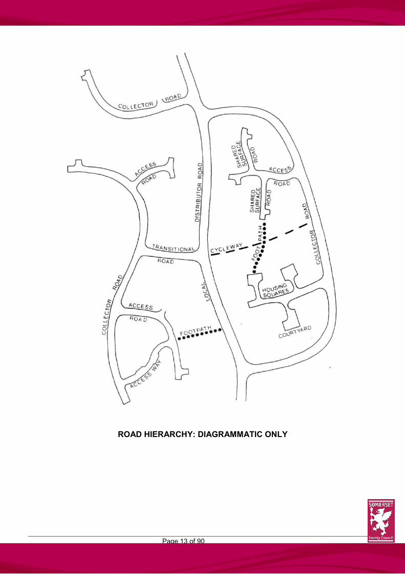
2.3.2 Appendix 2 of the Parking Guide in Section 4 sets out the parking Bay requirements for disabled drivers, wheel0chair users and ambulant disabled people and such provision should be made at all appropriate locations. The main provisions are indicated below.
Page 22 of 90
2.3.3 Steps and ramps will be accepted only in exceptional circumstances where the topography dictates. They will be in the locations agreed with the Engineer but will not in any case be acceptable on a footpath which is the sole means of access for emergency services to any property. If steps are unavoidable, suitable ramps or alternative routes to cater for wheel-chairs or prams should be provided. Steps, ramps, landings and approach paths shall be adequately lit and drained. Hand-rails, either free standing or fixed to parapet walls as appropriate, should be provided at changes in level and a low rail should be included for detection by blind people using canes.
2.3.4 Street furniture should be readily distinguishable from surroundings and be carefully sited. Note should be made of legislation covering the height and width of projecting awnings and signs. Windows and doors shall not open over the highway. Drainage gullies and covers shall be located so far as not to impair pedestrian or disabled movement at crossing points.
2.3.5 Adequate, convenient and safe crossing points should be provided with drop kerbs and
ramps with textured surfacing used in appropriate locations.

Page 23 of 90
2.4 EMERGENCY SERVICES
2.4.1 The attention of developers is drawn to the requirements of the emergency services. Access for Fire Service vehicles should be provided to within 45m of the entrance of all one and two-storey premises and to within 36m of the entrance of three or four-storey town houses, blocks, flats and maisonettes.
Access for Fire Service vehicles should be continuous, that is to say from one or more positions it must be possible to approach all dwellings sharing a common address. It is not sufficient that different groups of dwellings sharing a common address should be approachable from one of several positions. Access for Fire Service vehicles should normally be to the front of dwellings but rear access may be acceptable in some cases. The Home Office currently recommends a minimum width of carriageway of 3.7m for access roads. This width gives access at a reasonable pace together with operational space at the scene. Simply to reach an incident, carriageways of 3.0m width may be acceptable but this can only be in situations where no obstructions are caused by parked vehicles. This width, therefore, will be acceptable on access ways only where the appropriate passing places are provided. Bends should not be sharper than 5.0m radius and headroom should be at least 3.7m. (See 4.5.3 for details of structures over adoptable highways.) The Chief Fire Officer should be consulted where access limitations are expected.
2.4.2 For Ambulance personnel purposes, there should be no steps on the principal access route. (See 2.3.3.)
2.4.3 It is essential that street names, even if only of a temporary nature initially, be erected
prior to the occupation of any dwelling, for the benefit of emergency services, doctors, etc. The appropriate District Council should, therefore, be approached at an early stage to obtain street names. The District Councils are also the House Numbering Authority.

Page 24 of 90
2.5 OTHER SERVICES
2.5.1 It should, in general, be regarded as unreasonable that a dustbin should have to be carried more than 25m to the collecting vehicle. The Designer is advised to consult with the appropriate District Council; however, to determine any local requirements on bin-haul distance and/or vehicles used which can dictate layouts.
COMMUNAL COLLECTION
INDIVIDUAL COLLECTION Bin collection distances should generally not be greater than the distances indicated above.

Page 25 of 90
2.6 TRAFFIC CALMING MEASURES
2.6.1 As set out in section 2.1, the estate road hierarchy should provide an easily understood arrangement for reducing vehicle speeds on a progressive basis until vehicle movement is down to near walking pace. Drivers must be aware on entry and throughout the layout that they are in surroundings where the needs of pedestrians and cyclists take precedence over the convenience and free flow of vehicles. Conditions have to be created, therefore, under which the great majority of drivers will normally proceed with care and maintain low speeds without undue frustration. The action of a few selfish drivers cannot be reasonably catered for.
2.6.2 Very few accidents occur in culs-de-sac and with vehicle speeds of less than 20mph a significant reduction in both the number and the seriousness of accidents are achieved. With non-access traffic excluded drivers are usually residents, delivery personnel or visitors who will be familiar with the area.
2.6.3 The Government have introduced a consultation paper entitled “20mph Speed Limit
Zones – Draft Guidelines” and it is clear that should legislation be introduced in the future for such speed limits then it will be on a zonal basis and not applied to individual roads. It is important therefore that the design of new estate roads should achieve speed reductions by other means particularly where the estate roads form a small residential area.
2.6.4 The Highways (Road Humps) Regulations 1990 permit humps to be used as a means
of reducing speed of traffic subject to a number of restrictions. It is considered, however, that road humps and their required associated signing and road markings are more appropriate as remedial measures on existing roads and the aim in new development should be to use other speed restraints as described below.
2.6.5 Culs-de-sac - vehicle speeds on the roads are related to the effective length of straight and long culs-de-sac without some means of restraint must be avoided. The use of short culs-de-sac thus avoiding the need for other restraints may be to the developer’s advantage. Set against this, however, is the inconvenience caused to milkmen, postmen and the like and catering for pedestrian movements.
2.6.6 ‘T’ junctions – road junctions by themselves have a calming influence on vehicle speeds and can be used to great effect subject to appropriate visibility requirements.
2.6.7 Speed Control Bends – are very effective at reducing vehicle speeds and layouts are given in section 3.13. In general design terms carriageway widening is required on bends depending on the radius used. This can invite higher speeds in certain locations, however, and consideration should be given to mountable hard shoulders for use by larger delivery vehicles rather than general carriageway widening. These should be paved with sets to discourage pedestrians from using them and should be used preferably where other pedestrian facilities are available.

Page 26 of 90
Visibility through the inside of bends is required to the stopping sight distances set out in section 3.10.
2.6.8 Plateaux - ramps and plateaux may be used at a side road junction to raise the side road above the level of the priority road. The raised level may be continued throughout the length of the side road. A plateau may be used to raise the carriageway at a junction providing a speed restraint along the priority road as well as the side road. Such arrangements, however, will only be considered within a reasonable area of development served by Transitional or Collector Roads and cannot be used in isolation. Such plateaux must meet with the provisions of the Highways (Road Humps) Regulations 1990.
2.6.9 The effectiveness of most speed restraints may be enhanced by landscape features and positioning of buildings.
2.6.10 Restricted visibility, in the absence of other precautions, cannot be considered a
satisfactory means of reducing vehicle speeds. For safety drivers must be able to see a potential hazard in time to slow down or stop comfortably before reaching it.
2.6.11 Speeds can be further reduced by affecting a drivers perception of road types utilising
changes in materials and differences in level at junctions. 2.6.12 The Highway (Road Humps) Regulations 1990 require appropriate signing, white lining
and lighting. The designer should bear in mind these requirements when considering the aesthetic appearance of the street scene. Advice should be sought from the Engineer at an early stage.

Page 27 of 90
2.7 PEDESTRIAN MOVEMENT
2.7.1 The safe convenient surroundings for the movement of pedestrians is one of the fundamental elements of estate design. Layouts for larger developments should not be looked at in isolated sections but comprehensively to ensure that the eventual directions likely to be taken by pedestrians are catered for. People usually wish to take the most direct, convenient and safe route to their destination whether it be to schools, shops, play areas, bus stops, etc.
2.7.2 Whilst the security element as set out under section 2.2 must be considered there will be instances where paths linking culs-de-sac will be necessary but these should,
(i) be kept to a minimum; (ii) not link shared surfaces;
(iii) be kept as short as possible;
(iv) be overlooked by dwellings;
(v) have no sharp bends;
(vi) be adequately lit;
Such footpaths may be used for emergency or maintenance purposes in which case they shall be at least 3.0m wide, be of equivalent construction of the carriageways which they link and have bollards (knock-down or padlocked) to prevent general use by vehicles.
2.7.3 Any through pedestrian route must not be along shared surfaces. 2.7.4 To summarise the main points, pedestrian routes should:-
(i) be safe, convenient and direct for the likely movements; (ii) be of the easiest practicable gradient;
(iii) be overlooked by dwellings or passing traffic;
(iv) provide for adequate and suitable crossing points at appropriate locations,
including for wheel-chair users and people pushing prams;
(v) include for adequate visibility;
(vi) provide for verges between carriageway and footway along heavily trafficked roads;

Page 28 of 90
(vii) give practical access for those who make regular door-to-door deliveries or collections
(viii) be of adequate width and alignment to cater for wheel-chairs or prams
passing, underground services, heavy usage such as outside schools and, in certain instances, occasional access for emergency and maintenance vehicles.
Width considerations are set out below.
MINIMUM COMFORTABLE WIDTHS TO ACCOMMODATE VARIOUS PEDESTRIANS
A localised narrowing of a pedestrian route to overcome a particular obstruction may be acceptable providing a minimum width of 900mm is available.
Page 29 of 90
2.8 CYCLING PROVISION
2.8.1 When significant numbers of cycling movements are likely to be generated by large residential developments or to commercial areas or a small development needs to be integrated into a wider network of provision for cyclists, it will be necessary to consider providing cycleways contiguous with, but segregated from, footpaths or footways or unsegregated routes available to both cyclists and pedestrians. In other areas where only low levels of cycling are expected the road layout should provide safe and convenient conditions for cyclists.
2.8.2 Cycling on footways and footpaths is illegal. Powers contained within the Highways Act
1980, however, allow all or part of a footway to be converted to cycle use as a cycleway. Section 3 of the Cycle Tracks Act 1984 provides a procedure for converting all or part of a footpath to a cycleway.
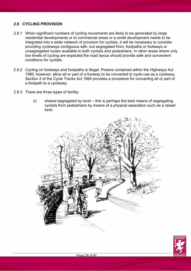
2.8.3 There are three types of facility:
(i) shared segregated by level – this is perhaps the best means of segregating cyclists from pedestrians by means of a physical separation such as a raised kerb;

Page 30 of 90
(ii) shared segregated by surface treatment – this could be either by a change of
surface material or by a continuous white line which has been shown to be effective;
(iii) shared unsegregated – in instances where there is a limited area available, although this approach is not recommended.
The design details are laid out under section 3.7.
2.8.4 Cycle facilities will be required around roundabouts and this may result in large splitter islands and wider paths. Adequate and safe crossing points will be required and, depending on the flow of cyclists which may exist or could be generated, may require the provision of signalled cycle crossings whether this be separate signalled cycle crossings or combined pedestrian/cycle crossings.
2.8.5 Further information is contained in the Department for Transport’s Local Transport Notes but it is suggested that the designer contact the Engineer at an early stage to consider the implications of cycleways.

Page 31 of 90
2.9 PUBLIC TRANSPORT
2.9.1 Since deregulation of the bus industry under the Transport Act 1985, bus operators are
free to run services wherever they see a commercial opportunity. Many operators use smaller vehicles for services, although clearly this could change depending on demand. In general, therefore, the use of a residential road as a bus route does not necessarily warrant its designation as a Distributor Road.
2.9.2 Given the usual method of picking up or setting down passengers within estates bus pull-
ins will not usually be required although special provision will have to be made at heavily used locations and stops on distributor or other higher category roads. The positioning of such a facility will be dependent upon the usual design and safety criteria and fit in with pedestrian routes.
Page 32 of 90
2.10 STATUTORY SERVICES
2.10.1 As well as making provision for pedestrian vehicular movement most residential roads and footpaths provide routes for statutory and other service underground. These services are an essential and integral part of the layout and their efficiency and safety in use are vital.
2.10.2 It is the developer’s responsibility to co-ordinate all Statutory Authority works, and early
consultation should be undertaken to determine requirements in terms of planning, layout and protection. (See section 5.4)
2.10.3 It is in the interests of residents that all services should be economical to install and
maintain. The provision of adequate access for operational and maintenance purposes is essential.
2.10.4 Services, apart from foul sewers and surface water drainage, should be laid under
adoptable footpaths, footways or service strips for several reasons:-
(i) the reduced likelihood of creating obstruction to traffic whilst maintenance or repairs are carried out and thereby limiting inconvenience to, and frustration of, road users;
(ii) reducing trench reinstatement costs perhaps passing the savings, indirectly,
onto customers;
(iii) limiting the visual effect of reinstatement;
(iv) avoiding the need for wayleaves or easements across individual properties. The provision of services, therefore, can have an influence on the design of certain layouts and the designer is encouraged to consult with the Statutory Authorities at an early stage.
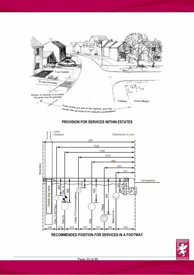
2.10.5 The recommended positions of mains along straight lengths of estate roads are shown opposite. It should be noted that an additional width may be required on changes of alignment, both vertically and horizontally, or where both high voltage and low voltage cables are laid. Where dwellings are to be connected to gas mains, a minimum distance of 2.0m is required between the building and centre line of the main.
2.10.6 Within Conservation Areas where special surface finishes, such as paviors laid to
patterns are proposed, full ducting for services may be required by the Engineer of Statutory Undertakers.
Page 33 of 90
PROVISION FOR SERVICES WITHIN ESTATES
RECOMMENDED POSITION FOR SERVICES IN A FOOTWAY

Page 34 of 90
3 DESIGN DETAILS
3.1. TYPE 1 (iii) LOCAL DISTRIBUTOR ROAD
DESIGN CRITERIA
SPEED 40/30 mph CARRIRAGEWAY WIDTH 7.3m (6.75m in approved cases) FOOTWAY WIDTH 2 No at 1.8m MAXIMUM GRADIENT 1 in 14 MINIMUM GRADIENT 1 in 100 without channel blocks 1 in 180 with channel blocks CURVATURE HORIZONTAL Minimum radius 100m. Adverse camber should
be eliminated on bends sharper than 300m radius.
CURVATURE VERTICAL Vertical curves must be introduced at all
changes of gradient using the following equation:
A main framework road linking residential areas. Access to individual properties will not be permitted. However, in order to provide an attractive setting for properties which adjoin the road developers are encouraged to construct a landscape area and earth mounding at the highway boundary. Such an area will assist with screening of the road and act as a noise barrier for the properties.
Page 35 of 90
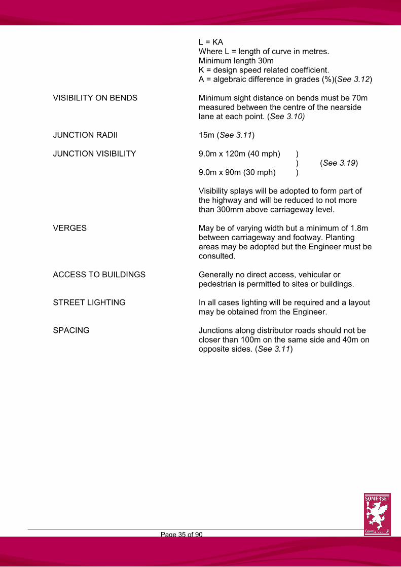
L = KA Where L = length of curve in metres. Minimum length 30m K = design speed related coefficient. A = algebraic difference in grades (%)(See 3.12)
VISIBILITY ON BENDS Minimum sight distance on bends must be 70m
measured between the centre of the nearside lane at each point. (See 3.10)
JUNCTION RADII 15m (See 3.11) JUNCTION VISIBILITY 9.0m x 120m (40 mph) )
) (See 3.19) 9.0m x 90m (30 mph) ) Visibility splays will be adopted to form part of
the highway and will be reduced to not more than 300mm above carriageway level.
VERGES May be of varying width but a minimum of 1.8m
between carriageway and footway. Planting areas may be adopted but the Engineer must be consulted.
ACCESS TO BUILDINGS Generally no direct access, vehicular or
pedestrian is permitted to sites or buildings. STREET LIGHTING In all cases lighting will be required and a layout
may be obtained from the Engineer. SPACING Junctions along distributor roads should not be
closer than 100m on the same side and 40m on opposite sides. (See 3.11)

Page 36 of 90
3.2 TYPE 2 – TRANSITIONAL ROADS
.
DESIGN CRITERIA DESIGN SPEED 30 mph CARRIRAGEWAY WIDTH 6.0m FOOTWAY WIDTH 2 No at 1.8m MAXIMUM GRADIENT 1 in 14 MINIMUM GRADIENT 1 in 100 without channel blocks 1 in 180 with channel blocks CURVATURE HORIZONTAL Minimum radius 60m. Where less than 75m the
carriageway should be widened by 0.5m CURVATURE VERTICAL Vertical curves must be introduced at all
changes of gradient. Minimum length 30m LENGTH Minimum of 30m
Short lengths of road linking Collector Roads to Local Distributor Roads and serving not more than 300 dwellings

Page 37 of 90
VISIBILITY ON BENDS Minimum sight distances on bends must be 60m measured between the centre of the nearside lane at each point. (See 3.10)
JUNCTION RADII 10m (15m where the Local Distributor Road
design speed is 40mph). (See 3.11) JUNCTION VISIBILITY 9.0m x 120m (40 mph) ) ) (See 3.9) 9.0m x 90m (30 mph) ) VISIBILITY SPLAYS Visibility splays will be adopted to form part of
the highway and will be reduced to not more than 300mm above carriageway level.
VERGES If required may be of varying width but a
minimum of 1.8m between carriageway and footway. Planting areas may be adopted but the Engineer must be consulted.
ACCESS TO BUILDINGS No direct or indirect access for vehicles or
pedestrians. STREET LIGHTING In all cases lighting will be required and a layout
may be obtained from the Engineer. SPACING No junctions are permitted along the length of
the transitional road but it will form the stem of a ‘T’ with Collector Roads. (See 3.11)
TRANSITIONAL ROAD JUNCTIONS

Page 38 of 90
3.2 TYPE 3 – COLLECTOR ROAD
DESIGN CRITERIA DESIGN SPEED 30 mph CARRIRAGEWAY WIDTH 5.5m FOOTWAY WIDTH 2 No at 1.8m MAXIMUM GRADIENT 1 in 14 MINIMUM GRADIENT 1 in 100 without channel blocks 1 in 180 with channel blocks CURVATURE HORIZONTAL Minimum radius 60m CURVATURE VERTICAL Vertical curves must be introduced at all
changes of gradient. Minimum length 30m EFFECTIVE STRAIGHT The length of effective straight is measured
between the junction with a type 1 or 2 road and a speed reducing bend or other speed reducing
These form the estate road framework and collect traffic from lower residential roads and link with Transitional Roads or Distributor Roads. They may serve up to 200 dwellings if a cul-de-sac or up to 400 dwellings if the road has two junctions.
Page 39 of 90
measure. The maximum length of effective straight is 120m.
SPEED REDUCING BEND 30m radius VISIBILITY ON BENDS Minimum sight distances on bends measured
between the centre of the nearside lane at each point must be 60m for a horizontal curve or 35m for a speed reducing bend. (See 3.10)
JUNCTION RADII 10m (15m where the Distributor Road design
speed is 40mph). (See 3.11) JUNCTION VISIBILITY 9.0m x 90m (120m where the Distributor Road
design speed is 40mph) (See 3.9) Visibility splays will be adopted to form part of
the highway and will be reduced to not more than 300mm above carriageway level
TURNING HEADS All culs-de-sac must have a turning head to one
of the designs shown. (See 3.15) VERGES If required may be of varying width but a
minimum of 1.8m between carriageway and footway. Planting areas may be adopted but the Engineer must be consulted
ACCESS TO BUILDINGS Direct or shared private drive serving no more
than two dwellings with adequate turning facilities within the curtilage
LENGTH OF CUL-DE-SAC Where Collector Road is a cul-de-sac normally
no access to a building should be more than 200m from the main road junction
STREET LIGHTING In most cases lighting will be required and a
layout may be obtained from the Engineer SPACING Junctions along Collector Roads are not
normally to be spaced closer than 60m on the same side and 30m on opposite sides (40m where the Distributor Road design speed is 40mph). (See 3.11).

Page 40 of 90
3.4 TYPE 4 (i) – ACCESS ROADS
DESIGN CRITERIA
DESIGN SPEED 20 mph or less CARRIRAGEWAY WIDTH 5.0m FOOTWAY WIDTH Usually 2 No at 1.8m, although one footway only
may be accepted in a short cul-de-sac or where there is single-sided development. In these instances, however, a 1.0m minimum width verge will be required in lieu of the second footway
MAXIMUM GRADIENT Generally no steeper than 1 in 14 MINIMUM GRADIENT 1 in 100 without channel blocks 1 in 180 with channel blocks CURVATURE HORIZONTAL Minimum inner radius 20m. Where less than
30m the carriageway should be widened by 0.5m
Access Roads will usually be culs-de-sac providing direct vehicular access to dwellings or to lower category roads. They will serve up to 100 dwellings and will be generally not longer than 100m.

Page 41 of 90
CURVATURE VERTICAL Vertical curves must be introduced at all changes of gradient. Minimum length 20m
EFFECTIVE STRAIGHT The length of effective straight is measured
between the junction with a type 3 road to a speed reducing bend or other speed reducing measure. The maximum length of effective straight is 60m
SPEED REDUCING BEND 20m radius. Carriageway should be widened on
the inside by 0.5m. (See 2.6.7 and 3.13) VISIBILITY ON BENDS Minimum sight distances on bends must be 33m
measured between the centre of the nearside lane at each point. (See 3.10)
JUNCTION RADII 6.0m (See 3.11) JUNCTION VISIBILITY 4.5m x 90m (See 3.9) Visibility splays will be adopted to form part of
the highway and will be reduced to not more than 300mm above carriageway level
TURNING HEAD All culs-de-sac must have a turning head which
may be of an irregular shape but must accommodate one of the designs shown. (See 3.15)
VERGES The Engineer to be consulted ACCESS TO BUILDINGS Direct or shared private drive serving no more
than two dwellings. LENGTH OF CUL-DE-SAC Generally less than 100m. Normally no access
to a building should be more than 100m from the main road junction.
STREET LIGHTING In most cases lighting will be required and a
layout may be obtained from the Engineer. SPACING Junctions should not be closer than 30m on the
same side or 20m on opposite sides. (See 3.11)

Page 42 of 90
TYPE 4 (ii) – ACCESS WAYS
DESIGN CRITERIA
DESIGN SPEED 20 mph, or less CARRIRAGEWAY WIDTH Generally 3.0m with widening at junctions and
with inter-visible passing places. See diagram opposite.
FOOTWAY WIDTH 1 No at 1.8m. A verge on the opposite side of at
least 0.5m width to allow for vehicle overhang but preferably 1.0m width to allow for future hedge growth, etc. should be provided
MAXIMUM GRADIENT Generally no steeper than 1 in 14 MINIMUM GRADIENT 1 in 100 without channel blocks 1 in 180 with channel blocks CURVATURE HORIZONTAL Minimum inner radius 20m. Where less than
30m the carriageway should be widened by 0.5m
Access Ways will have two junctions with either Collector or Access Roads, but not form a short-cut. They will serve up to 25 dwellings at a density not exceeding six per acre (15 per hectare).

Page 43 of 90
CURVATURE VERTICAL Vertical curves must be introduced at all changes of gradient. Minimum length 20m
EFFECTIVE STRAIGHT The length of effective straight is measured
between the junction with a type 3 or 4 road to a speed reducing bend or other speed reducing measure. The maximum length of effective straight is 60m
SPEED REDUCING BEND 20m radius. Carriageway should be widened on
the inside by 0.5m. (See 2.6.7 and 3.13) VISIBILITY ON BENDS Minimum sight distances on bends must be 33m
measured between the centre of the nearside lane at each point. (See 3.10)
JUNCTION RADII 6.0m. (See 3.11) JUNCTION VISIBILITY 4.5m x 90m (4.5m x 60m where the junction is
onto an access road). (See 3.9) Visibility splays will be adopted to form part of
the highway and will be reduced to not more than 300mm above carriageway level
VERGES The Engineer to be consulted ACCESS TO BUILDINGS Direct or shared private drive serving no more
than two dwellings. LENGTH OF ACCESS WAY Generally less than 100m. No access to a
building should be more than 100m from the main road junction
STREET LIGHTING In most cases lighting will be required and a
layout may be obtained from the Engineer.
LAYOUT OF ACCESS WAYS
Page 44 of 90
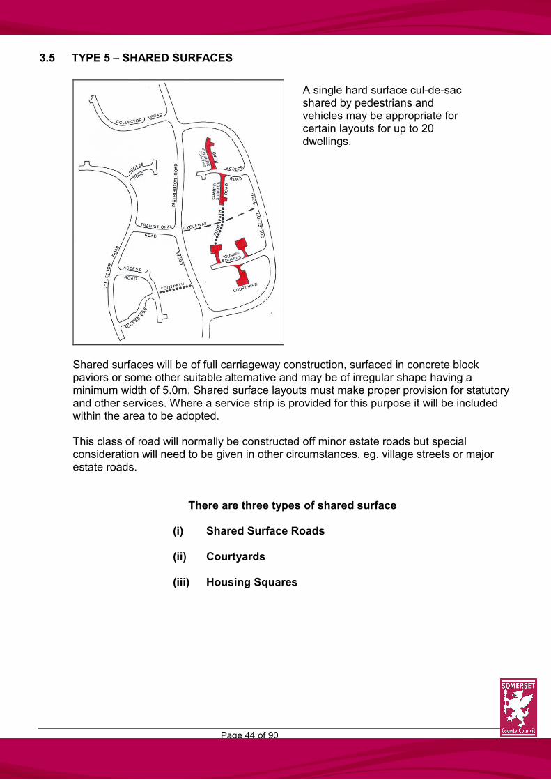
3.5 TYPE 5 – SHARED SURFACES
Shared surfaces will be of full carriageway construction, surfaced in concrete block paviors or some other suitable alternative and may be of irregular shape having a minimum width of 5.0m. Shared surface layouts must make proper provision for statutory and other services. Where a service strip is provided for this purpose it will be included within the area to be adopted. This class of road will normally be constructed off minor estate roads but special consideration will need to be given in other circumstances, eg. village streets or major estate roads.
There are three types of shared surface
(i) Shared Surface Roads (ii) Courtyards (iii) Housing Squares
A single hard surface cul-de-sac shared by pedestrians and vehicles may be appropriate for certain layouts for up to 20 dwellings.
Page 45 of 90
DESIGN CRITERIA FOR ALL SHARED SURFACES
DESIGN SPEED 15 mph, or less MAXIMUM GRADIENT Generally no steeper than 1 in 14 MINIMUM GRADIENT 1 in 100 CURVATURE VERTICAL There should be no sudden change of gradient
except at the junction where dropped kerbs or ramps may be used.
EFFECTIVE STRAIGHT The length of effective straight is measured
between the junction with the type 4 road and a speed reducing bend or other speed reducing measure. The maximum length of effective straight is 40m
SPEED REDUCING BEND 5.0m internal radius. Carriageway should be
widened on the inside by 1.0m. (See 2.6.7 and 3.13)
JUNCTION Junctions can be taken from the arms of a
turning head or directly from the access road. Where it forms the straight on extension of an access road a speed reducing ramp must be provided at the turning head. Junctions along an access road can take two forms:-
(i) a normal junction with a 4.0m radii or (ii) a crossing of the footway by introducing a
10m length of dropped kerb. In this case splays at the back of footway of dimensions 2.4m x 2.4m will be required
JUNCTION VISIBILITY 2.4m x 60m. (See 3.9) TURNING HEAD May be of irregular shape but large enough to
contain one of the standard turning heads. Where the shared surface is less than 30m long the dimensions may be reduced by 20%. (See 3.15)
VERGES Minimum of 0.5m, 1.0m around turning heads
and will be adopted

Page 46 of 90
ACCESS TO DWELLINGS Direct or private drives serving not more than two dwellings or communal parking in housing squares.
LENGTH OF CUL-DE-SAC Not more than 100m measured from the main
road carriageway edge. STREET LIGHTING In most cases lighting will be required and a
layout will be provided by the Engineer.
Page 47 of 90
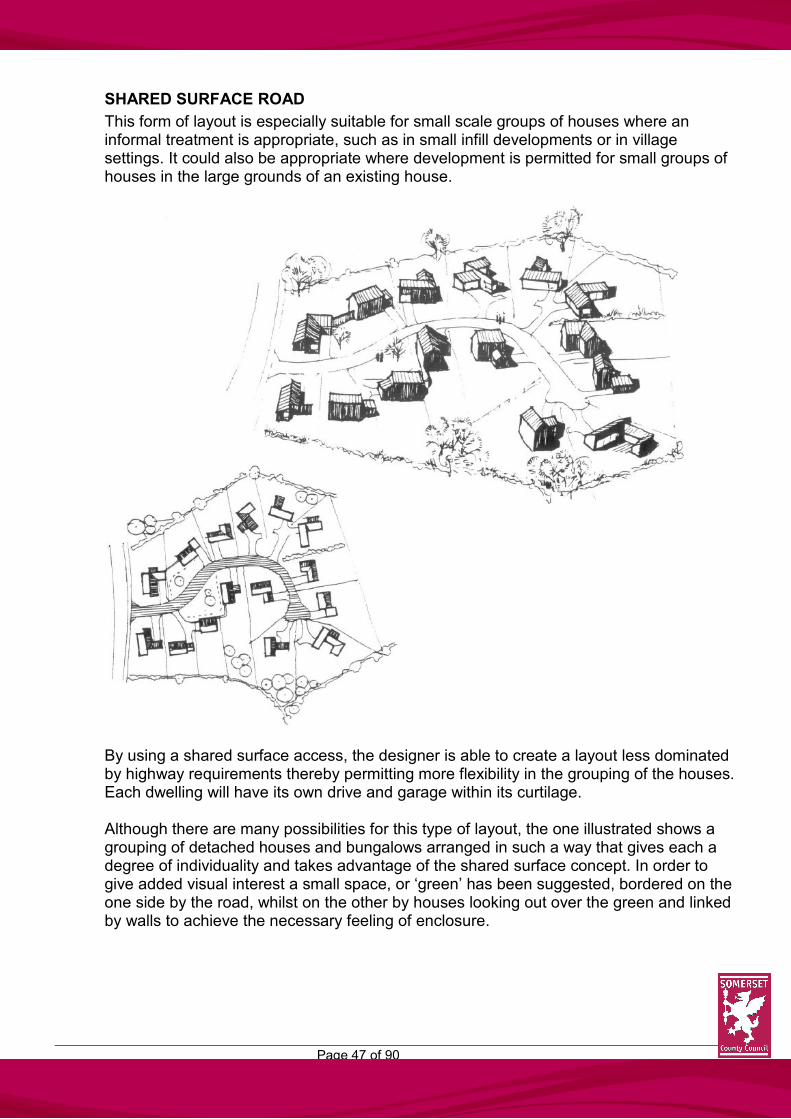
SHARED SURFACE ROAD
This form of layout is especially suitable for small scale groups of houses where an informal treatment is appropriate, such as in small infill developments or in village settings. It could also be appropriate where development is permitted for small groups of houses in the large grounds of an existing house.
By using a shared surface access, the designer is able to create a layout less dominated by highway requirements thereby permitting more flexibility in the grouping of the houses. Each dwelling will have its own drive and garage within its curtilage. Although there are many possibilities for this type of layout, the one illustrated shows a grouping of detached houses and bungalows arranged in such a way that gives each a degree of individuality and takes advantage of the shared surface concept. In order to give added visual interest a small space, or ‘green’ has been suggested, bordered on the one side by the road, whilst on the other by houses looking out over the green and linked by walls to achieve the necessary feeling of enclosure.

Page 48 of 90
COURTYARD
This type of layout gives the designer great flexibility in the arrangement of the dwellings and the design of the central space.
In the example illustrated, the two and three storey houses and flats are arranged loosely around the courtyard, with additional pedestrian routes to the court (some could be provided under buildings). The reason for suggesting three storey buildings in the scheme is that the car parking can be provided within the ground floor with the living accommodation above – a popular arrangement in high density urban locations. Private gardens, where these are provided within the courtyard, can be walled to achieve added seclusion and security and the surface paving to both the road and the forecourts can be in a similar material in order to heighten the visual impact of the space.

Page 49 of 90
HOUSING SQUARE
The housing square is a variant of the shared surface concept and provides the designer with the opportunity to provide a layout where the houses, usually semi-detached or in terraces, are set around a large central space which is both landscaped and contains the car parking space for the residents.
The example in the illustration shows a possible form of layout, with the car parking spaces divided into two areas and landscaping and tree planting included to improve the visual appearance. Delivery, service and emergency vehicles are able to use the main access routes.

Page 50 of 90
3.6 TYPE 6 – FOOTPATHS
DESIGN CRITERIA
WIDTH Normally not less than 1.8m but can be 3.0m or more depending on particular circumstances.
MAXIMUM GRADIENT Generally not steeper than 1 in 14 STEPS Normally not acceptable, (see 2.3, 2.4 and 2.7).
However, where steps are acceptable they should not be less than 2.0m wide. They shall not exceed 12 risers of 150mm without a landing, which shall be the same width as the flight and be not shorter than 2.0m.
ALIGNMENT Sharp corners and changes of direction should
be avoided because of the difficulties of lighting and policing.
JUNCTION A pedestrian safety barrier may be required at
junctions of footpaths with carriageways, cycleways or footways.
Linear hard surface routes intended solely for the use of pedestrians, which do not follow the line of the carriageway. The Highway Authority will normally only adopt those footpaths which serve as a main pedestrian link. Footpaths included for purely amenity reasons together with public open space may be adopted by the District Council.

Page 51 of 90
DRAINAGE All footpaths will be adequately drained. It may be possible to drain the surface with a single crossfall but, if constructed between walls, gullies will be required.
LIGHTING In most cases lighting will be required and
specification can be obtained from the Engineer. RAMPS Ramps should be 2.0m wide and not longer than
10m, at a gradient preferably 1 in 20 but, in case, not steeper than 1 in 14. Where a ramp exceeds 10m a 2.0m level landing is required at mid length.
HANDRAILS May be required for steps and ramps as directed
by the Engineer.

Page 52 of 90
3.7 TYPE 7 – CYCLEWAYS
DESIGN CRITERIA
WIDTH Normally not less than 2.0m for unsegregated use, 3.0m for segregated use (1.5m each for pedestrians/cyclists).
GRADIENTS Where the length of the cycleway is unrestricted,
maximum gradient of 1 in 33. For lengths up to 100m, maximum gradient of 1
in 20. For lengths up to 30m, maximum gradient of 1 in
14 CROSSFALL Normally 1 in 40. ALIGNMENT Cycleways do not need to be on a straight
alignment but where there is a change of direction the minimum centre line radius shall be 6.0m.
To meet the needs of cyclists Cycleways will be required in connection with new development proposals for both residential and commercial development where there is a clear need. Where provided they will be adopted as part of the public highway.

Page 53 of 90
JUNCTION WITH ESTATE ROAD Where a cycleway crosses an estate road or other highway the entry should be at 90° and the cyclist should be encouraged to slow down or stop as necessary. Dropped kerbs should be provided at the crossing points, and barriers may be required. Where a cycleway which is heavily trafficked crosses a distributor road with high vehicular flows consideration will be given to the provision of an under-pass/over-pass or a signalised crossing.
DRAINAGE All cycleways will be adequately drained. It may
be possible to drain the surface with a single crossfall but, if constructed between walls, gullies will be required. A positive drainage system will be required where it is considered that natural drainage will be inadequate.
LIGHTING In all cases lighting will be required and a
specification can be obtained from the Engineer. VISIBILITY ON BENDS Minimum sight distance on bends is 20m
measured along the centre line of the cycleway on gradients of 1 in 50 or less and 26m where gradients exceed 1 in 50.
JUNCTION VISIBILITY Where a cycleway crosses a footway or
footpath, provision shall be made for unobstructed vision to users of both.
At road crossings visibility splays shall be
provided with a ‘x’ distance of 4.5m and a ‘y’ distance based on the design speed of the road. (See 3.9).
Visibility splays will be adopted to form part of
the highway and be reduced to not more than 300mm above carriageway level.
HEADROOM Headroom should normally be at least 2.7m and
horizontal clearance of obstacles should be at least 0.25m but preferably 0.5m.
SIGNING / LINING Will be required to the satisfaction of the
Engineer.
Page 54 of 90
3.8 TYPE 8 – PRIVATE DRIVES
3.8.1 These will not be adopted and will rarely serve more than two dwellings.
Contrived layouts of adjoining drives as an attempt to reduce lengths of adoptable roads may be considered unacceptable by the Engineer.
3.8.2 Private drives will give access to dwellings off Type 3 roads (with turning space provision
within the curtilage) and Type 4 and 5 roads only, except at the Engineers discretion. 3.8.3 Care should be exercised as to the positioning of access points, avoiding proximity to
junctions especially on the main route where drivers signals can be misinterpreted. 3.8.4 Drive gradients should not be steeper than 1 in 10 but the design must not take into
account the cross-fall of the adjoining highway to prevent the grounding of vehicles at the rear of the footway/verge.
3.8.5 Adequate provision for the collection of surface water must be made within each plot to
avoid such water flowing onto the highway. 3.8.6 Driveways should meet the highway at right angles. 3.8.7 Adequate turning space shall be provided to enable a vehicle to be driven onto the
highway in a forward gear where:- (i) direct access is off type 3 roads; (ii) in proximity to junctions;
(iii) drives would otherwise entail reversing over 20m;
(iv) in other locations as considered necessary by the Engineer.
3.8.8 At all private vehicular access points a minimum of four dropped kerbs shall be provided
set with a vertical face of 25mm, plus tapers. Where the frequency of access points is such that there would be less than three intervening full-face kerbs in the area between those accesses those kerbs shall also be dropped and the footway constructed as a vehicular crossing.
3.8.9 Visibility splay requirements are shown in Section 3.9, together with additional visibility
details at the rear of footways shown below.

Page 55 of 90
Additional visibility requirements between drivers and pedestrians at private drives

Page 56 of 90
3.9 VISIBILITY AT JUNCTIONS
3.9.1 Visibility criteria are derived from the Department of Transport Department Advice Note TA20/84 “Junctions and Accesses: The Layout of Major/Minor Junctions”, and Planning Policy Guidance Note 13 “Highway Considerations in Development Control”, which may be briefly summarised as follows:-
Drivers approaching a major/minor junction from the minor road should have unobstructed visibility to the left and right along the major road, for a distance depending on the major road traffic speed, to enable them to judge safely when they may turn into or cross the major road. This visibility also allows the drivers on the major road to be aware of traffic entering from the minor road in time for them to be able to slow down or stop safely if this should be necessary. Visibility splays are defined by:- (i) A line of length ‘X’ measured along the centre line of the side road from the
continuation of the line of the near edge of the main road carriageway. (ii) A line of length ‘Y’ measured along the near edge of the main road carriageway
from its intersection with the centre line of the side road.
(iii) The straight line joining the termination of the above lines.
(iv) Where the main road bends visibility will be taken forward of a line drawn between line ‘X’ and tangential to the curve providing always that the full ‘Y’ length is secured.
(v) Where a crest exists in the vertical alignment of the main road full inter-visibility is
required between the ‘X’ and ‘Y’ dimensions. (See 3.12).

Page 57 of 90
3.9.2 No trees or shrubs will be permitted within the sight lines at junctions (but see 4.3.3).
Generally nothing should be higher than 300mm above carriageway level within the visibility splay. All visibility splays will be adopted as highway and in no circumstances should they be conveyed to the adjoining owners.
3.9.3 Although estate developments normally take place in built-up areas the following table
gives ‘Y’ distances for all situations:- Table A: Used where vehicle speeds on major roads are known (85 percentile wet weather)
Major Road Speed (mph) 75 62 53 44 37.5 30* 30** 25 20
Major Road Distance (Metres) 295 215 160 120 90 70 60 45 33
Table B: Used where there is a speed limit on the major road (actual speed not known)
Speed Limit (mph) 70 70 50 40 30* 30**
Major Road Distance (Metres) 295 215 160 120 90 60
* Where major road is not an access road but a higher category road
** Where major road is an access road with speeds universally below speed limit
‘Main Road’ is used to define the road on to which the estate road is to connect.
The ‘X’ distance will normally be 9m although for less busy, simple and very minor junctions the ‘X’ distance may be reduced to 4.5m.
DIAGRAM INDICATING ‘X’ DISTANCE
For Type 5 Shared Surface Roads constructed off minor estate roads the ‘X’ distance may be 2.4m and, in exceptional cases, 2.0m as indicated in Planning Policy Guidance Note 13 (PPG. 13).

Page 58 of 90
It is recognised that cases can arise where although development is otherwise appropriate, site difficulties make it impossible to comply with the full requirements and designers are advised to show the maximum visibility possible and submit this for consideration in the light of the factors which affect the site.

Page 59 of 90
3.10 VISIBILITY AT BENDS
The developers attention is drawn to Design Bulletin 32 (HMSO) paragraphs 5.13 to 5.23 and Appendix 3. These may be briefly summarised:- (i) The eye level of drivers can vary from 1.05m above the carriageway in a
standard car to approximately 2.0m in a large commercial vehicle. To enable drivers to see each other across summits, across bends at junctions, unobstructed visibility will be required at least between these heights above the carriageway.
For drivers to see and be seen by pedestrians however, particularly child pedestrians, unobstructed visibility will be required to a point closer to the ground. The height of a very young child of walking age is around 800mm but the height of a child on a tricycle can be even lower. As general guidance it is suggested that a height of 600mm be taken as the point above which unobstructed visibility should be provided wherever the potential exists for conflicts between motorists and young children. This will apply along most sections of the residential road system and especially where shared pedestrian/vehicular surfaces are used. The most obvious obstructions to visibility are summits, adjacent buildings, screen walls, dense planting and parked cars. Particular care should be taken in the choice and location of ground-cover planting. Generally the aim should be to ensure good visibility without having to rely on frequent maintenance and therefore to choose only those species of ground-cover plants with very low growth potential. (ii) The horizontal distance over which unobstructed visibility should be maintained
will depend upon the stopping distance of vehicles. This in turn will depend upon vehicle speeds, deceleration rates and drivers’ reaction times. The table opposite gives a range of stopping distances commensurate with various vehicle speeds. The distances are intended to cater for the majority of vehicles and drivers in most weather conditions and may be used as general guidance in the design of the residential road network.
Forward visibility splays on bends will be adopted as highway. In certain circumstances they may be covered by covenants to ensure that anything either placed, planted or erected in the vision area is not permitted to exceed a height of 600mm above adjacent carriageway level. These areas should normally not include garage drives or parking spaces.
DRIVERS’ LINE OF SIGHT FOR DIFFERENT VEHICLES

Page 60 of 90
FORWARD VISIBILITY SPLAY
METHOD OF CONSTRUCTION OF FORWARD VISIBILITY SPLAY
To construct a forward visibility curve around a bend:- (i) a line should be drawn parallel to the kerb, 1.5m into the carriageway
to represent the path of the vehicle; (ii) the required stopping distance commensurate with the expected
speed of the vehicle should be ascertained and measured back along the vehicle path from the tangent point A;
(iii) the stopping distance should then be divided into equal increments of
approximately 3.0m and the increment points numbered in sequence;
(iv) the same stopping distance with the same number of increments should then be repeated around the curve, finishing at a full stopping distance beyond the tangent point B;
(v) The area which has to be kept clear of obstruction
should then be constructed by joining increments of the same number together, ie 1 to 1, 2 to 2, etc.
Page 61 of 90
3.11 JUNCTION LAYOUT DETAILS
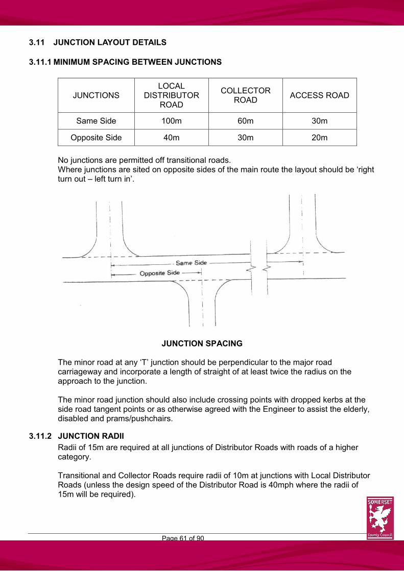
3.11.1 MINIMUM SPACING BETWEEN JUNCTIONS
JUNCTIONS LOCAL
DISTRIBUTOR ROAD
COLLECTOR ROAD
ACCESS ROAD
Same Side 100m 60m 30m
Opposite Side 40m 30m 20m
No junctions are permitted off transitional roads. Where junctions are sited on opposite sides of the main route the layout should be ‘right turn out – left turn in’.
JUNCTION SPACING
The minor road at any ‘T’ junction should be perpendicular to the major road carriageway and incorporate a length of straight of at least twice the radius on the approach to the junction. The minor road junction should also include crossing points with dropped kerbs at the side road tangent points or as otherwise agreed with the Engineer to assist the elderly, disabled and prams/pushchairs.
3.11.2 JUNCTION RADII
Radii of 15m are required at all junctions of Distributor Roads with roads of a higher category. Transitional and Collector Roads require radii of 10m at junctions with Local Distributor Roads (unless the design speed of the Distributor Road is 40mph where the radii of 15m will be required).

Page 62 of 90
Junctions of Access Roads and Shared Surfaces require radii of 6.0m and 4.0m respectively.
THE EFFECT OF JUNCTION RADII ON SWEPT PATHS
Pantechnicons are able to turn without interfering with traffic on the through road
Refuse vehicles are able to turn without interfering with traffic on the through road or side road
Pantechnicons are able to turn but use most of the width of both carriageways
Refuse vehicles are able to turn without interfering with traffic on the through road
Vehicles larger than private cars use most of the width of both carriageways
Vehicles larger than private cars use most of the width of both carriageways

Page 63 of 90
3.12 VERTICAL ALIGNMENT
3.12.1 Forward visibility on vertical curves shall be that required in the tables shown section 3.9, and measured on longitudinal sections as shown below to achieve 1.05m to 0.26m inter-visibility.
3.12.2 It is necessary to limit the severity of vertical curves because of the visibility considerations on the brow of hills and for the comfort of vehicle occupants.
Vertical curves should be parabolic because this form provides a constant rate of change of curvature. It is convenient to determine the length of a vertical sag or crest curve using a ‘K’ value. The length of curve can be obtained from the equation:
L=KA Where L = curve length (m) K = design speed related coefficient A = algebraic difference in grades (%) For Local Distributor Roads the ‘K’ value must be obtained from current Department for Transport standards. For other roads a constant of 6 is applicable.
3.12.3 The maximum gradient usually acceptable for all roads will be 1 in 14. There will be
certain locations within Somerset where this might prove difficult but the developer should contact the Engineer at the earliest opportunity to discuss individual problem sites.
3.12.4 At all junctions a platform shall be provided at a gradient not exceeding 1 in 20 for a
distance of at least 6.0m, from the major road channel line to assist drivers in pulling away smoothly, especially during inclement weather. These are minimum criteria and where possible flatter gradients and longer platform lengths should be provided.

Page 64 of 90
3.12.5 Minimum channel gradients of 1 in 180 where channel blocks are used and 1 in 100 otherwise shall be provided. When concrete block paviours are used the minimum acceptable gradient shall be 1 in 100.
It should be noted that it is not good practice to design vertical alignments along the centre line where only minimum gradients are achievable. This can lead to drainage problems and ponding on the channel line within turning heads and junctions and care must be exercised to obtain adequate falls in such locations.

Page 65 of 90
3.13 SPEED CONTROL BENDS
3.13.1 Speed may be restricted by the introduction of a bend of certain dimensions. This bend would have a maximum centre line radius appropriate to the type of road with vehicles turning through a minimum angle of 70 degrees and not more than 90 degrees
SPEED CONTROL BEND
These bends may be used to limit the length of ‘effective straight’ in order to achieve the required design speed for a particular road.
3.13.2 An essential feature of a speed control bend is the interruption of the line of straight-on vision of the driver approaching the bend from either direction so as to reinforce the change of direction. This should be achieved by a wall or building or dense planting to rapidly attain a height of 2.0m not less than 0.5m or generally more than 3.0m from the far side of the carriageway.
FEATURES OF SPEED CONTROL BENDS
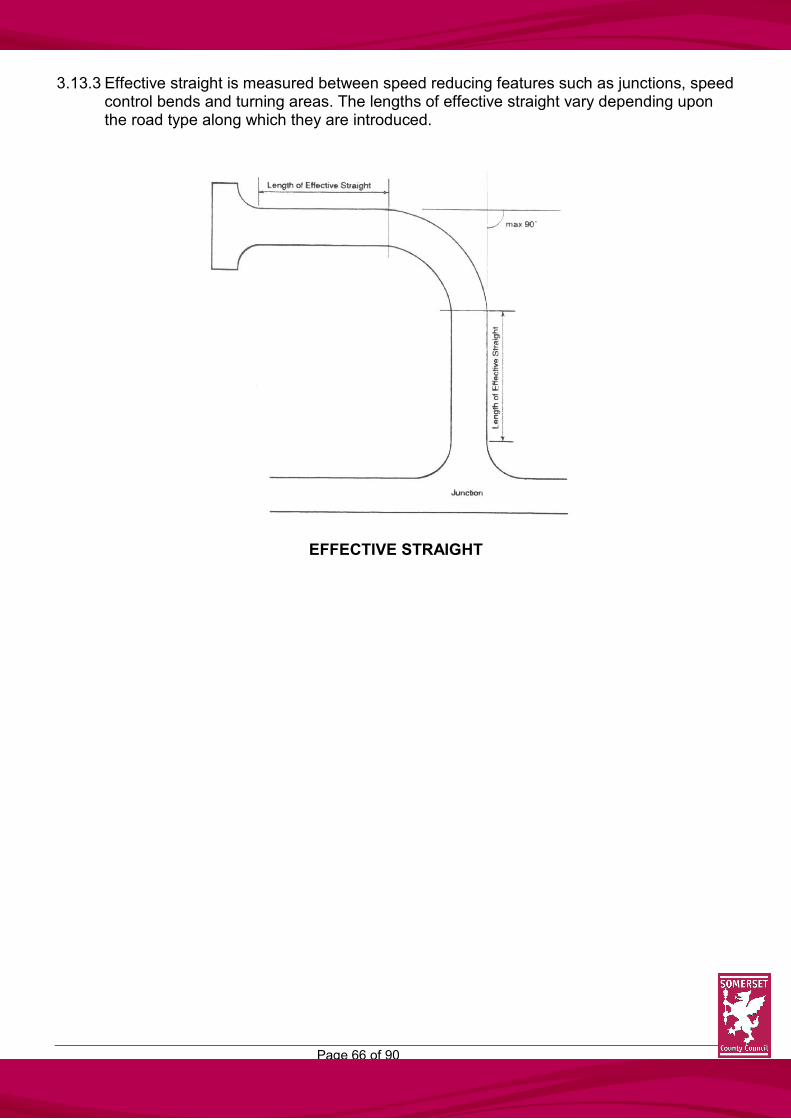
Page 66 of 90
3.13.3 Effective straight is measured between speed reducing features such as junctions, speed control bends and turning areas. The lengths of effective straight vary depending upon the road type along which they are introduced.
EFFECTIVE STRAIGHT

Page 67 of 90
3.14 SURFACE WATER DRAINAGE
3.14.1 An adequate system of drains shall be provided for the collection and disposal of surface water from estate roads.
3.14.2 The granting of planning permission does not imply that the technical problems of any
site can be overcome economically. It is essential that the disposal of highway surface water be investigated at the outset with the Authority concerned. It must not be assumed that permission will automatically be given by the Engineer to make a connection to a highway drain in a publicly maintained road.
It is the designer’s responsibility to secure satisfactory outfall arrangements and evidence
will be required that the developer has a right to discharge surface water at the proposed point of outfall.
3.14.3 Designers are reminded that under the provision of the Land Drainage Act 1976, any
works, including sewers, bridges, roads, discharge structures and tree planting in close proximity of a statutory ‘main river’ requires the consent of the National Rivers Authority. Any culverting, infilling or diversion of any water course also requires the consent of the National Rivers Authority or Internal Drainage Board where appropriate. Under the provisions of the Water Act 1989 the discharge of surface water into any water course, ditch or soakaway may require the consent of the National Rivers Authority.
3.14.4 Soakaways, as a means of disposal of highway surface water will normally not be
accepted unless there are very special circumstances, and will only be considered as a final resort after all engineering means to provide a positive drainage system have been explored and found to be unrealistic.
The use of soakaways will be at the discretion of the Engineer and only after it has been
demonstrated, by on-site investigation, percolation tests and calculations that permeable strata exist, and can cope with the whole of a once-in-five-year twelve hour storm.
If accepted, soakaways must be sited within the areas to be adopted, and be so located
such that carriageway or footway formation or construction is not affected by ground water. Silt traps shall be incorporated into the inlet of any soakaway and be so positioned to ensure that access is readily available for maintenance purposes.
3.14.5 If soakaways are used for the disposal of roof water or other surface water run-off they
must be so located to avoid being detrimental to adjoining highway construction. 3.14.6 Where drainage systems are proposed to carry other than solely highway surface water,
ie roof water, the Highway Authority will adopt gullies and their connections only. In these circumstances the sewers will be the subject of an Agreement with the Water Authority or its Agent, in accordance with Section 18 of the Public Health Act 1936.
3.14.7 Where highway drains deviate from the public highway and cross private land a formal
Easement is required, usually over a 6.0m width for the length of the drain to give the Highway Authority right of access at all times for repair and maintenance purposes. Acknowledgement of the presence of such a drain under each affected property must be

Page 68 of 90
safeguarded by the incorporation of a suitable Easement within the conveyance of the property by the developer. No surface water drain to be adopted shall pass below a building or other structure.
3.14.8 Individual or combined accesses and other areas not to be adopted shall be designed so
as not to discharge water onto the highway. Special considerations will be required for industrial premises, garages and such like to prevent, by way of petrol interceptors, noxious substances finding their way onto the highway and/or into highway drains.
3.14.9 Weep-holes in retaining walls abutting the highway or down-pipes from any building shall
not discharge onto any footway or carriageway. 3.14.10 Pedestrian and vehicle barriers may be required in certain situations, where for instance
ditches or rhynes run alongside carriageways or pedestrian routes, at headwalls, sustaining structures or high embankments.
3.14.11 If, as part of a development proposal, widening of a highway is necessary any gullies or
manholes existing therin shall be repositioned on the new channel line as directed by the Engineer. (See also 5.2.11).
3.14.12 Sub-soil drainage may be required to pick up any springs or ground water encountered to
ensure that the water table is permanently reduced to a level 600mm below carriageway formation level.
3.14.13 Manholes shall be provided at the head of drains, (except where rodding eyes are
acceptable to the Engineer); at changes of direction, pipe size or gradient; at the junction of main drains; and at spacings not exceeding 100m. Manholes may be constructed of pre-cast concrete ring sections or brickwork as detailed in the Specification.
3.14.14 Gullies shall be in locations approved by the Engineer and special consideration will be
required at road junctions, individual access points, low spots in sag curves and where any superelevation is applied. As a general guide each gully will drain up to 150m2 of highway with additional gullies required where the gradient is steeper than 1 in 40 and flatter than 1 in 150.
Gully connections should not exceed 15m in length. At road junctions gullies should be positioned up-stream of the tangent point and clear of
pedestrian/wheel-chair crossings and private drives. Double gullies, each with a separate connection, shall be provided at the low-spot in sag
curves and within turning heads as required. Where superelevation is applied, a gully is required just short of the point at which
adverse camber is removed to prevent surface water flowing over the carriageway. 3.14.15 Both foul and surface water drainage runs shall be designed so that wherever possible
any maintenance operations are not likely to obstruct both traffic lanes and manhole covers do not fall within wheel-tracks.

Page 69 of 90
The design of pipe runs, etc is more fully covered in the Specification. (See 3.16.6) 3.14.16 Developers shall ensure that any testing of, and required remedials to, drains that pass
under any part of the carriageway or footway from houses, or sewers to be adopted by the Water Authority or their Agents is carried out before construction of any part of the carriageway or footway.
Any private drains passing through or under areas to be adopted must be recorded and the maintenance responsibility clearly defined in a covenant attached to deeds for a specific parcel of private land.
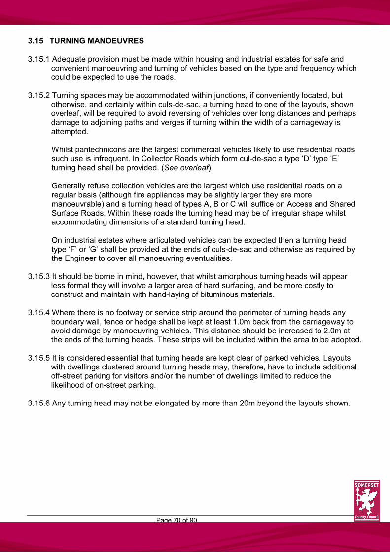
Page 70 of 90
3.15 TURNING MANOEUVRES 3.15.1 Adequate provision must be made within housing and industrial estates for safe and
convenient manoeuvring and turning of vehicles based on the type and frequency which could be expected to use the roads.
3.15.2 Turning spaces may be accommodated within junctions, if conveniently located, but
otherwise, and certainly within culs-de-sac, a turning head to one of the layouts, shown overleaf, will be required to avoid reversing of vehicles over long distances and perhaps damage to adjoining paths and verges if turning within the width of a carriageway is attempted. Whilst pantechnicons are the largest commercial vehicles likely to use residential roads such use is infrequent. In Collector Roads which form cul-de-sac a type ‘D’ type ‘E’ turning head shall be provided. (See overleaf)
Generally refuse collection vehicles are the largest which use residential roads on a regular basis (although fire appliances may be slightly larger they are more manoeuvrable) and a turning head of types A, B or C will suffice on Access and Shared Surface Roads. Within these roads the turning head may be of irregular shape whilst accommodating dimensions of a standard turning head.
On industrial estates where articulated vehicles can be expected then a turning head type ‘F’ or ‘G’ shall be provided at the ends of culs-de-sac and otherwise as required by the Engineer to cover all manoeuvring eventualities.
3.15.3 It should be borne in mind, however, that whilst amorphous turning heads will appear less formal they will involve a larger area of hard surfacing, and be more costly to construct and maintain with hand-laying of bituminous materials.
3.15.4 Where there is no footway or service strip around the perimeter of turning heads any
boundary wall, fence or hedge shall be kept at least 1.0m back from the carriageway to avoid damage by manoeuvring vehicles. This distance should be increased to 2.0m at the ends of the turning heads. These strips will be included within the area to be adopted.
3.15.5 It is considered essential that turning heads are kept clear of parked vehicles. Layouts
with dwellings clustered around turning heads may, therefore, have to include additional off-street parking for visitors and/or the number of dwellings limited to reduce the likelihood of on-street parking.
3.15.6 Any turning head may not be elongated by more than 20m beyond the layouts shown.

Page 71 of 90

Page 72 of 90
Page 73 of 90
3.16 STREET LIGHTING
3.16.1 In almost all circumstances the Highway Authority will require the developer to provide a street lighting system for roads and paths which are to be adopted as highway maintained at the public expense. In rural locations the wishes of the Parish Council are usually respected and lighting may not be required.
3.16.2 When detailed planning permission has been granted for the development proposed and
the layout has been approved by the Engineer, the designer shall submit three copies of the approved layout drawing. One copy of the drawing will be returned to the designer showing the required siting of the lamp columns, together with a detailed equipment and installation specification.
3.16.3 Street lighting is basically provided for the safety of both vehicular and pedestrian traffic
but other considerations, such as policing, amenity and environmental aspects are taken into account. All street lighting layouts will, in general, comply with the design criteria as detailed in the various constituent parts of British Standard Code of Practice BS 5489 or its successors.
3.16.4 The developer shall be responsible for the implementation of all work required in the
removal, replacement or resting of any existing lighting equipment made necessary by the site works, whether or not such work was detailed within the original street lighting drawings or specification. This work may involve the total removal and disposal of units from site and/or the replacement/resiting of units within the general area affected by site works. No existing lighting shall be switched off, dismantled or removed without prior written approval of the Engineer.
3.16.5 Where a site lies beyond the limits of an existing lighting scheme it may be necessary for
the intervening section to be lit at the expense of the developer. Early consultation with the Engineer is essential.
3.16.6 The standard specification of materials and construction for street lighting together with
the completion and commissioning procedures are set out in ‘The Specification’. (See 3.14.15).

Page 74 of 90
4 OTHER DESIGN FEATURES
4.1 CAR PARKING
4.1.1 A major element of road safety within estates is the elimination of, or at least a major
reduction in, parking on the carriageway. In almost half of all pedestrian accidents and a quarter of vehicular accidents in residential areas the presence of a parked vehicle is reported. On-street parking creates difficulties for emergency services, delivery and service vehicles and, indeed, residents themselves. Visually it is unsatisfactory and maintenance problems are increased by larger vehicles overriding kerbs and footways to pass parked vehicles.
4.1.2 Experience shows that drivers tend to park as close to the front doors of houses to which
they are going, and residents wish to have convenient parking for other practical needs such as car-washing and servicing and minimising the risks of car thefts and vandalism. Large and remote garaging or parking courts should therefore, be avoided. Every effort must be made to incorporate the required parking standards within the curtilages of dwellings which they are intended to serve. It is appreciated that this may not be achieved with terrace housing but housing squares should then perhaps be considered. Any layouts which do not provide for convenient parking and, therefore, likely to induce on-street parking, especially close to junctions or within turning heads, will not be accepted.
4.1.3 The Local Planning Authority advise on parking for any particular development but
standards are determined in consultation with the Highway Authority and the current requirements, together with the minimum dimensions, are set out in a separate booklet. ‘PARKING – Guidance for Developers on Vehicle Parking Standards in Somerset’.
4.1.4 Special care must be taken to ensure that parking provision does not interfere with
visibility, particularly at junctions and on the inside of bends. Where a parking space is provided in front of a garage a minimum drive length of 6.0m should be available to allow a vehicle to be parked clear of the highway whilst the garage door is being opened or closed.
4.1.5 It should also be borne in mind that any private or communal parking will not normally be
adopted by the Highway Authority. In certain circumstances to avoid ‘islands’ of non-adopted areas, parking may be taken over but as such it will be available for public use, will be subject to highway and road traffic legislation and cannot be allocated to particular properties. A commuted sum to cover future maintenance of these areas may be required of the developer.
The areas for adoption must be adequately delineated, the actual means will be dependent on the surfacing materials used and will be agreed with the Engineer.

Page 75 of 90
4.2 LANDSCAPING
4.2.1 Poor or non-existent landscaping along Distributor, Transitional and Collector Roads contribute to residents low levels of satisfaction with an estates general appearance, given that in the main, no direct access is permitted and road users are therefore faced with blank walls and fences of rear gardens.
It is recommended therefore that designers allow for areas of landscaping along such roads, these being of variable but not too narrow width to further soften the overall appearance. A good mix of both evergreen and deciduous species will afford screening which is effective throughout the year and allows some seasonal variation.
4.2.2 Landscaping must not impair visibility requirements of and for drivers and pedestrians both from a road safety and personal safety aspect. Visibility splays at certain road junctions should not be planted, others to varying degrees as set out later, but tall dense planting in particular locations should be avoided so as not to create secluded areas for anyone with criminal aspirations to lurk.
Landscaping and planting associated with footpaths and at junctions of footpaths with footways should reinforce security planting but, as a general rule, should not exceed 1.0m in height. Planting should be graded with taller plants next to walls or fences, lower plants and shrubs adjacent to paths. Skilful use of climbing plants can assist in preventing graffiti where it might be expected.
4.2.3 Planting does have to be carefully specified as:
(i) shrubs with prickly thorns such as gorse, berberis, holly or hawthorn may be
suited to deterring short-cuts by pedestrians. However, they should not be used alongside paths where potential damage to pedestrian clothing or personal injury is likely to arise as a result of overhanging of the highway;
(ii) the likely maximum attainable height of trees and shrubs must be taken into
account so that the effectiveness of street lighting schemes will subsequently not be reduced.
4.2.4 Landscaped areas will not normally be adopted by the Highway Authority. There may be
instances where planting within highway limits will be acceptable if it forms part of an overall landscape scheme. In these cases the future maintenance liability must be discussed with the Engineer.

Page 76 of 90
4.3 RETENTION OF EXISTING TREES AND HEDGES
4.3.1 Where possible, existing trees should be retained and protected during construction works. This requires more than the simple identification on plan of selected specimens if it is to succeed and where doubts exist expert advice must be sought. Two important factors have to be borne in mind: (i) 95% of trees roots are to be found in the top metre of soil, and (ii) The root spread of a tree often exceeds its crown spread by a considerable
distance
It is, therefore, necessary to erect temporary protective fencing during the construction period and this should be to the dimensions shown in the diagram below. The area within the protective fence must be kept free from vehicles, the storage of materials, tipping or fires and there should be no changes in ground level or excavations within the area. Developers are advised to refer to BS 5837 (1980) – The Code of Practice for Trees in Relation to Construction.
4.3.2 Similarly, existing hedges can be incorporated to good effect in new housing areas and
where this is intended appropriate protective measures must be taken. Additional planting can also be used to renovate and augment existing hedgerows.
4.3.3 Existing trees within visibility splays are not encouraged but where the Local Planning
Authority considers a rare or particularly good specimen is worth keeping the Highway Authority will give due consideration to a request for its retention.

Page 77 of 90
4.4 NEW PLANTING
4.4.1 The need for new planting to supplement existing landscape features on the site of newly built housing cannot be stressed too strongly. Planting should be provided on a generous scale and the designer is urged to involve the services of a qualified landscape architect from the outset who will be able to advise on particular species best suited to the soil and drainage characteristics of the site.
4.4.2 Shrubs and ground cover plants can quickly improve the appearance of new housing
areas and, once established, require little maintenance especially compared with grassed areas. They are ideal for breaking up expanses of otherwise hard materials such as occur in parking areas or garage courts. Screening with hedges or 1.0m high bankings and small shrubs can ensure that these areas are landscaped into the overall layout.
4.4.3 The design of landscaped areas, whether to be adopted or adjoining the highway, must
also take account of future maintenance liabilities whilst providing for an attractive soft environment. Small isolated areas of planting, including grass, should be avoided as indeed should narrow strips of less than 1.0m alongside carriageways or footways. It should be noted that under Section 141 of the Highways Act 1980, no tree or shrub shall be planted in a made-up carriageway or within 4.5m of the centreline of a made-up carriageway.
4.4.4 Normally planted areas will not be adopted unless such areas can be shown to contribute
to the appearance or function of the highway. Such instances will be alongside Distributor, Transitional or Collector Roads where no direct access is permitted. On lower category roads planting will be the responsibility of the developer, Local Authority or householder.
4.4.5 Ground cover planting in general will be acceptable within verges and service strips and
in some circumstances within visibility splays. Visibility splay criteria are related to carriageway levels but it should be remembered that the road cross section includes a 125mm kerb upstand and a rising crossfall over verge or footway, which at major junctions can give a significant level difference. Considerable care must be taken, therefore, to choose species which will not exceed 300mm ultimate height.
The appropriate tree, shrub or ground cover species should be selected to reflect the location in which they are to be used. Where planting is proposed within highway limits full landscaping details shall be submitted to the Engineer for approval. Standard trees should be adequately staked, tied and protected and provision should be made for maintenance and replacement planting.
4.4.6 Care must be exercised when choosing species for planting within service strips to
ensure a shallow root system thus avoiding potential damage to services. It must also be borne in mind that should maintenance and trench opening be necessary and disturbance of planting take place, the relevant Statutory Undertaker is under no obligation to replace planting as found. Neither is the Highway Authority, although every effort would be made to return the area to its earlier state.

Page 78 of 90
Where no services exist within a verge and highway visibility splay requirements are not affected, other planting may be accepted provided that visibility from private accesses is not impaired.
4.4.7 All areas of highway to be adopted, whether planted or not, must be delineated in a
manner to be agreed with the Engineer.
It must also be made clear to purchasers of adjoining plots that where a verge or service margin to be adopted is contiguous with a private garden/lawn the rights of the Highway Authority and Statutory Undertaker have to be protected.
4.4.8 Many planting schemes fail due to inadequate attention to planting procedures,
unsatisfactory maintenance and non-replacement of losses and the Highway Authority, in the absence of a suitable maintenance agreement with the developer, would look to the developer for a commuted sum to cover the high maintenance costs in the early years.
4.4.9 Grass should not be laid up to vertical structures as hand trimming is then necessary. To
reduce maintenance requirements therefore a mowing strip at least 200mm wide should be constructed as per footway specification adjoining fences, walls, buildings etc. Within industrial estate roads, especially where fences and walls are subsequently erected clear of the adopted highway, the intervening strip should be hard paved to avoid it becoming a rubbish trap and therefore unsightly.
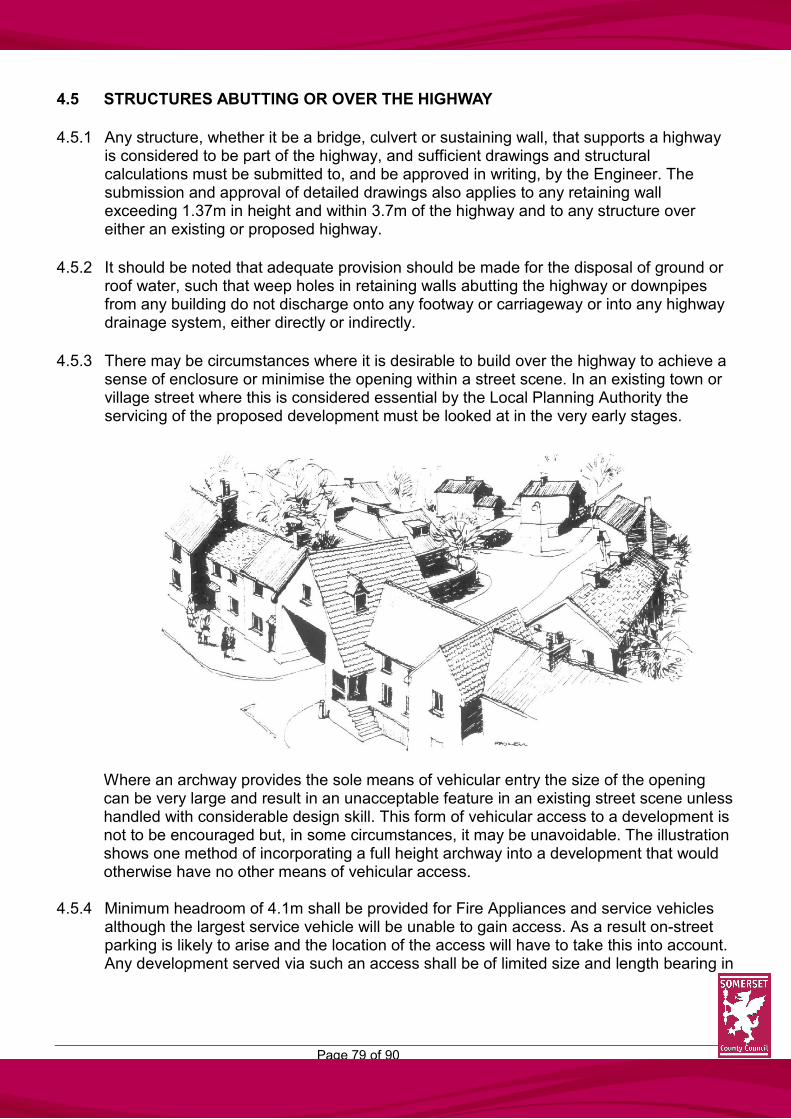
Page 79 of 90
4.5 STRUCTURES ABUTTING OR OVER THE HIGHWAY
4.5.1 Any structure, whether it be a bridge, culvert or sustaining wall, that supports a highway is considered to be part of the highway, and sufficient drawings and structural calculations must be submitted to, and be approved in writing, by the Engineer. The submission and approval of detailed drawings also applies to any retaining wall exceeding 1.37m in height and within 3.7m of the highway and to any structure over either an existing or proposed highway.
4.5.2 It should be noted that adequate provision should be made for the disposal of ground or roof water, such that weep holes in retaining walls abutting the highway or downpipes from any building do not discharge onto any footway or carriageway or into any highway drainage system, either directly or indirectly.
4.5.3 There may be circumstances where it is desirable to build over the highway to achieve a sense of enclosure or minimise the opening within a street scene. In an existing town or village street where this is considered essential by the Local Planning Authority the servicing of the proposed development must be looked at in the very early stages.
Where an archway provides the sole means of vehicular entry the size of the opening can be very large and result in an unacceptable feature in an existing street scene unless handled with considerable design skill. This form of vehicular access to a development is not to be encouraged but, in some circumstances, it may be unavoidable. The illustration shows one method of incorporating a full height archway into a development that would otherwise have no other means of vehicular access.
4.5.4 Minimum headroom of 4.1m shall be provided for Fire Appliances and service vehicles
although the largest service vehicle will be unable to gain access. As a result on-street parking is likely to arise and the location of the access will have to take this into account. Any development served via such an access shall be of limited size and length bearing in

Page 80 of 90
mind servicing and convenience considerations. As the structure would have to be treated as a low bridge adequate signing will be necessary. Changes in gradient within and abutting an arch should be borne in mind to ensure that minimum headroom is retained for the longest vehicle.
MINIMUM VERTICAL CLEARANCES
Elsewhere and on ‘green field’ development sites a minimum height restriction of 5.2m will apply such that all service traffic can be accommodated.
4.5.5 Early liaison with Statutory Undertakers is necessary to ensure that adequate widths are
available to cater for services. Additionally, the needs of pedestrians must be catered for but, in any case, rubbing strips of at least 05.m are required abutting the carriageway to allow for the overhang of vehicles. As any building or supporting pier will not form part of the highway damage resulting thereto will be a private civil matter and no responsibility will rest with the Highway Authority if all statutory procedures have been applied.
4.5.6 A licence is required from the Highway Authority under Section 177 of the Highways Act
to construct a building over any part of a highway currently or prospectively maintainable at the public expense.

Page 81 of 90
4.6 TRAFFIC SIGNS, ROAD MARKINGS AND STREET FURNITURE
4.6.1 Where major works or alterations to an existing highway are necessary to give access to development, signing and white lining will be required. They may also be required in other situations where, for instance, a new estate road meets an existing County road. Full details must be incorporated in the design and the approval of the Engineer must be obtained.
4.6.2 Where traffic signs are required by the Engineer they shall conform to BS 873. Where these are to be illuminated early notification will be given so that the appropriate ducting can be installed at the same time as that required for street lighting.
4.6.3 Pedestrian barriers to BS 3049(1976), or as otherwise specified, may be required by the Engineer where a footpath or cycleway meets an adoptable carriageway or its abutting footway and at corners on connecting footways or cycleways.
4.6.4 All street furniture shall be positioned such that it does not obstruct visibility splays, and is no closer that 450mm to the carriageway edge.
4.6.5 All works, including traffic signs, road markings and street lighting, required in connection with alterations and additions to existing public highways must be fully operational to the satisfaction of the Engineer before the connecting estate road is brought into use.
4.6.6 Where a structure over the highway is incorporated in the design appropriate signing will be required both on the structure and along the adjacent highway approaches.
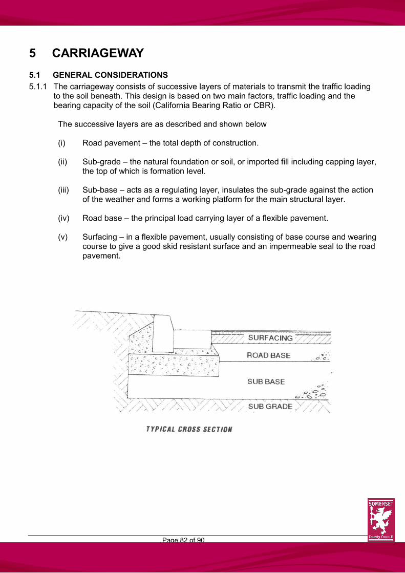
Page 82 of 90
5 CARRIAGEWAY
5.1 GENERAL CONSIDERATIONS
5.1.1 The carriageway consists of successive layers of materials to transmit the traffic loading to the soil beneath. This design is based on two main factors, traffic loading and the bearing capacity of the soil (California Bearing Ratio or CBR). The successive layers are as described and shown below (i) Road pavement – the total depth of construction. (ii) Sub-grade – the natural foundation or soil, or imported fill including capping layer,
the top of which is formation level.
(iii) Sub-base – acts as a regulating layer, insulates the sub-grade against the action of the weather and forms a working platform for the main structural layer.
(iv) Road base – the principal load carrying layer of a flexible pavement.
(v) Surfacing – in a flexible pavement, usually consisting of base course and wearing
course to give a good skid resistant surface and an impermeable seal to the road pavement.

Page 83 of 90
5.2 ROAD PAVEMENT DESIGN
5.2.1 The pavement designs are based on the Transport and Road Research Laboratory (TRRL) Lab Report 1132, as rationalised by the DTp Highway and Traffic Departmental Standard HD 14/87. The design of the capping and sub-base layers should allow for the construction traffic of the associated housing/industrial development, in addition to that for the road itself.
5.2.2 The bearing capacity of the sub-grade will vary from site to site, dependent on soil type
and, to a greater extent, on its moisture content. Assessment of the CBR value to be used for design will be made by the Engineer either from site investigation data submitted by the developer or in-house measurements, after detailed planning approval has been granted for an estate road layout.
All requests for soil tests and assessments of the sub-grade CBR value should be addressed to the Engineer (see Appendix A) and must be accompanied by authority to enter the land concerned stating the date from which entry is available. The assessment of the sub-grade CBR will normally require the excavation of trial pits for which the developer will be expected to provide a suitable mechanical excavator. It is the CBR value of the sub-grade at the particular location which determines the pavement layer thicknesses required. The Engineer will agree the appropriate capping and sub-base layers to be laid which must be shown and specified on the Section 38 drawings. Estate roads to be adopted through the Advanced Payment Code procedure or to be constructed by District Councils will also need to have the CBR of the sub-grade assessed and the thicknesses of the pavement construction layers agreed before construction starts. If the sub-grade is frost susceptible no material within 450mm of the road surface shall be susceptible to frost action.
5.2.3 In certain circumstances other forms of construction may be approved if they provide the
same strengths as the typical cross section. Work in Conservation Areas may require the use of special materials which in all cases must be approved by the Engineer before construction is commenced.
5.2.4 Embankment and cutting slopes shall be designed for stability, dependent upon soil type
and ground water conditions. Usually embankments will have a maximum slope of 1 in 2 and cuttings 1 in 1.5. Relatively flat margins of 600mm shall be provided at top and bottom of embankments and cuttings and junctions with slopes shall be roundly contoured. It should also be borne in mind that slopes included within amenity areas which are to be maintained by a District Council shall be no steeper than 1 in 4.

Page 84 of 90
5.2.5 Flexible surfacing should comply with the Specification, (see 3.16.6) which covers the supply, use and laying requirements of bituminous macadams and asphalts for new construction, maintenance and reinstatement works unless the developer seeks prior approval of the Engineer to an alternative.
5.2.6 The total thickness of the bituminous layers for Distributor Roads shall be in accordance
with Appendix A, Chart 3, of the DTp Standard HD 14/87. The allowable material types and thickness of the component layers shall be as shown in Appendix K of that Standard.
5.2.7 Industrial estate roads will be considered as Distributor Roads for pavement design
purposes. 5.2.8 The total thickness of bituminous layers for Residential Roads shall be as set out in the
Specification (see 3.16.6) 5.2.9 On gradients steeper than 1 in 20 the required polished stone value (PSV) for the
aggregate to be used in surfacing materials will be specified by the Engineer. 5.2.10 Concrete block paving shall be used on shared surfaces, pedestrian areas or as
otherwise acceptable to the Engineer. 5.2.11 Where widening of a highway is necessary as part of a development proposal the
crossfall of the existing highway shall be maintained and extended across the new works to the new channel line(s). In certain circumstances, where level difficulties arise, regulating of the existing highway may be required to achieve a satisfactory profile.

Page 85 of 90
5.3 DIVERSION OR STOPPING UP OF EXISTING HIGHWAYS
5.3.1 It is the responsibility of the developer to check whether or not any rights of way, public or private, will be affected by the proposed development. There may exist on the site a definitive public path, or public path not on the definitive map. It is not always acceptable for the proposed diversion simply to follow the proposed urban footway development. The existing footpath or bridleway may follow an attractive or commodious route that the District Council may wish to retain in order to avoid crossing estate roads or to give access to adjoining countryside or other country paths.
5.3.2 Where any development involves the diversion or stopping-up of an existing public
highway or County road then the required Order has to be obtained either under Part X (Sections 247, 248 and 249) of the Town and Country Planning Act 1990 from the Secretary of State, or the Highways Act 1980 (Sections 116, 118 and 119) and the Magistrates Court as appropriate.
The Wildlife and Countryside Act 1981 changed the procedures for diverting footpaths and bridleways, the County Council and the District Councils now being the main Order making Authorities, with Magistrates’ Court applications used in exceptional circumstances only. Given the various consultations which have to be undertaken prior to an Order being sought, early discussions with the relevant Authority are recommended.
5.3.3 Development must not take place on the route of the path nor indeed can a Section 38
Agreement relate to arrangements for the diversion or stopping-up of any public highway until the necessary Order has been confirmed.

Page 86 of 90
5.4 WORKS WITHIN AND ADJOINING EXISTING PUBLIC HIGHWAYS
5.4.1 Where, in connection with a development, works have to be undertaken within or adjoining a public highway the developer must apply to the Area Highways Manager or Technical Officer, as appropriate, for a Road Opening Licence (under Section 181) of the Highways Act 1980). The application must be made at least three weeks prior to the opening being required, and include a plan showing the full extent of the works proposed.
5.4.2 The developer shall liaise with the relevant Statutory Undertakers and Sewerage
Authority and give a minimum of seven days notice, in writing, as required under Section 182 of the Highways Act 1980. The developer shall be responsible for placing orders for the necessary Statutory Undertaker’s alterations and any costs associated therewith.
5.4.3 It is an offence to carry out works in a public highway without the consent of the Highway
Authority. The start of any development could be delayed, therefore, unless the above sections have been fully complied with.
5.4.4 Where works in a highway are such that the continuing passage of traffic would be
hazardous or difficult the developer may apply for a Temporary Closure of the highway.
The application should be made in the first instance to the Area Highways Manager or Technical Officer with whom details of the alternative route(s) should be agreed at least six weeks before the date of closure. The application must include a written agreement to indemnify the Authority against all claims that may arise by reason of the closure. The developer must also bear the cost of any strengthening works on the alternative route(s) to bring it up to the standard required to carry the diverted traffic. Making good damage caused by diverted traffic and providing and maintaining all signs required in connection with the diversion are also the responsibility of the developer. Adequate access to all affected land and premises must be maintained by the developer at all times.
5.4.5 Where work has to be carried out on, or adjacent to, an existing public highway or a
highway to which the public have access, the developer shall comply in all respects with the recommendations contained in Chapter 8, Traffic Safety Measures for Road Works, of the “Traffic Signs Manual” (HMSO).
The traffic signs, road markings, lamps, barriers, traffic control signals and vehicles shall be in accordance with the requirements of the current editions of “Traffic Signs, Regulations and General Directions 1981”.

Page 87 of 90
6 INDUSTRIAL ESTATE ROADS
6.1 ADDITIONAL DESIGN CONSIDERATIONS
6.1.1 The minimum carriageway width shall be 7.3m. 6.1.2 Footways will normally be required on both sides of an industrial estate road but see 4.2. 6.1.3 Adequate provision must be made within industrial estate roads for the convenient
turning of all vehicles likely to use those particular roads. Details of required turning heads are given in 3.15.
6.1.4 Junction spacings will be as set out in 3.11 as for a Local Distributor Road. Junction
Radii shall be a minimum of 15m. 6.1.5 Industrial estate roads will be considered as Distributor roads for road pavement design
purposes and will be surfaced in Hot Rolled Asphalt unless otherwise agreed with the Engineer.
6.1.7 On industrial estate roads the Engineer may require, in certain locations, that the
adjoining footway be constructed to the same materials and depths as the adjoining carriageway.
6.1.8 On industrial estate roads individual access points may be required as junctions rather
than footway crossings depending upon the likely use. In either case, however, the access shall be of the same construction as the adjoining carriageway.
6.1.9 The road pavement design of industrial roads will take due account of the heavier traffic
load, based on Chart 3 of HD 14/87, and in addition the possibility of subsequent extensions of the industrial area.

Page 88 of 90
6.1.10 Industrial estates (or business parks) require high standards of layout and design and sufficient accommodation for vehicles, staff and visitor car parking and outside working and storage areas.
Due to the uncertainty of individual industrial requirements for these estates or parks it is often difficult to obtain an overall design at the submission stage. Furthermore, some units will need to have room for expansion. For industrialists and visitors alike an attractive layout and design is necessary incorporating neat appearance and the use of imaginative landscaping.
However, the sheer size of some present day warehouses often unrelieved by any architectural design features and the large size of articulated vehicles (together with the space required for their manoeuvring) means that the design related to human scale is difficult to achieve. The site designer, therefore, will need to show how these features can be handled in a sympathetic way. Locations near to residential areas and, indeed, in open countryside sites adjacent to traffic inter-changes will be sites where the issue of scale will be particularly noticeable. Designers will need to accommodate individual site requirements ranging from large individual space users with large fleets of lorries to the smaller units and to office buildings where large numbers of staff parking will need to be accommodated. Size, shape, colour, site security and vehicular space will also need to be incorporated. An attractive layout will be seen by many as good business.

Page 89 of 90
APPENDIX A
A1 When outline planning consent has been granted, the developer will be requested, by letter, to submit to the Engineer for approval full details of the estate road(s) as regard layout, construction and surface water drainage.
A2 Seven copies of the layout plan, one coloured to show areas put forward for adoption,
together with two copies each of the longitudinal and cross sections are required to enable the Engineer to design the street lighting scheme, undertake CBR testing and forward one set of drawings to the Area Highways Manager who will supervise the works.
The layout plans should be at 1 in 500 scale, longitudinal sections at 1 to 500 horizontal and 1 to 50 vertical and cross sections at an appropriate but natural scale.
A3 Particular note should be made of 3.14.1 to 3.14.12. A4 The Engineer will confirm that all layout details are accepted and inform the developer
of road pavement construction requirements, provide a street lighting layout and specification and the amount of Bond required. The name and address of the developer’s Solicitor and Bondsman is requested at this stage, as is the superintendence fee (5% of the Bond figure), which is payable within 14 days of the signing of the agreement.
A5 One area which can frustrate and create delay is Proof of Title to the land to be covered
by the Agreement. The furnishing to the County Secretary and Solicitor of such proof at an early stage would assist its checking being carried out in parallel to the technical details. (See also sections 5.3 and 5.4)
A6 When agreement has been reached on all the estate road details seven sets of plans
are required coloured to show the areas and works to be adopted as follows:- Carriageway, including shared surfaces Light Brown Verges/visibility splays Light Green Footways/footpaths Grey Planted areas, if appropriate Dark Green Surface water drainage (highway exclusive) Blue Street light positions Red Estate/site ownership Outlined in Red A7 Should a developer wish to start the construction of dwellings before a Section 38
Agreement is signed it is necessary for the required Advance Payments Code deposits

Page 90 of 90
to be made for the appropriate plots. Such deposits, together with accrued interest, will be returned to the developer upon signing of the Agreement.
A8 The developer shall give the Engineer seven days notice in writing of the date upon
which road works will start or end or temporarily end and restart. At least 24 hours notice at each stage of the works is necessary to ensure adequate inspections can be made. Works covered up without the Engineer’s inspection may have to be proved at the developer’s expense.