Embed Size (px)
Citation preview

Scancon Tranevang 1 3450 Allerød Denmark Tlf +45 48 17 27 02 Fax +45 48 17 22 84 www.scancon.dk
SCA94DD
Technical Manual

Technical Manual – SCA94DD
Scancon Tranevang 1 3450 Allerød Denmark Tlf +45 48 17 27 02 Fax +45 48 17 22 84 www.scancon.dk
p. 2Rev. 1.0 17-July -2012
1 Introduction
The SCA94DD is a member of the Scancon eCODE Series of high resolution optical semi-absolute encoders. The eCODE encoders are communicating encoders that communicate over a standardized interface and therefore do not need any specialized hardware. All communication is handled by a powerful microprocessor which ensures low latency and short cycle time.
The encoders in this series use a precision interpolating optical system which provides high resolution and accuracy. All data from the interpolating system are processed by the microprocessor insuring that all position and other data is accurate and recent within a few microseconds. The eCODE series implements several programmable functions including resolution, direction of rotation and preset/reset functions. It also implements diagnostic functions with error and status. Programmable functions can be programmed by the customer or be programmed by Scancon according to the customer’s needs. This version of the eCODE encoder is particularly made to be used in wind power generation on slow rotating direct drive generators. Due to the very high resolution it is able to measure rotor speed and position quickly and with high accuracy. The SCA94DD has the following features:
Profibus Interface for exchange of data with a master controller.
Quadrature and Index Outputs, A, B and Z and the complementary A-, B- and Z-. Quadrature outputs are protected by the Scancon TSM (Transient Suppression Module).
RS485 Interface for set-up.
Measurement of Rotor Speed and Rotor Position.
Programmable Resolution of Quadrature Outputs
Programmable Direction of Rotation (Phase Sense).
Programmable Sample Time for Speed. This manual describes the implementation and use of the SCA94DD encoder.

Rev. 1.0 17-Ju
2 Phy
The draw
TerminaOn (up) Off (dow
MPr
uly -2012
ysical Lawing below s
ation resisto = Term
wn) = Term
M12 – 5 pin rofibus In
Tlf
ay-out shows the e
ors: mination Onmination Off
male
M23 – 12 pQuadratureRS485 InteEncoder Su
Scancon Tra+45 48 17 27 02
encoder with
n ff
pin male e Output erface upply
anevang 1 345 Fax +45 48 1
h the end ca
Index LE
50 Allerød Den17 22 84 www.
ap removed
aED
Technica
nmark .scancon.dk
.
Screw driveadjustment
MPr
al Manual
er slot in shof index po
12 – 5 pin frofibus Out
l – SCA94D
p
aft for oint
female
DD
p. 3

Technical Manual – SCA94DD
Scancon Tranevang 1 3450 Allerød Denmark Tlf +45 48 17 27 02 Fax +45 48 17 22 84 www.scancon.dk
p. 4Rev. 1.0 17-July -2012
3 Installation
As the installation of the SCA94DD may differ from location to location, it is not possible to give exact instructions on all aspects on how to install the encoder. Below are some general recommendations and procedures. 3.1 Mechanical Installation
To avoid electrical ground loops it is strongly recommended that the SCA94DD be electrically isolated from the generator. Ground loops may lower the encoder’s resistance to electrical disturbances. This means that both the encoder shaft and the housing should be isolated from the shaft and body of the generator. The encoder should be connected to ground through the cable shields which should then be connected to ground close to or at the controller. For the shaft, an isolated flexible coupling should be used. The isolation voltage should be 3kV or higher. For the encoder housing, isolated stand-offs or any fixture that can isolate the encoder from the generator can be used. An isolation voltage of 3 kV or higher should be used. If, for some reason, the encoder cannot be isolated from the generator, the cable shields must not be connected at the encoder end, as described in Section 5 below, as this will introduce a ground loop. This installation method is not recommended. 3.2 Alignment of Index Point
For the encoder to be calibrated to the rotor position after a power up, it is necessary for the encoder to revolve up to one revolution so the encoder can detect at least one index pulse to calibrate itself. The direction of rotation is not important. A completion of the calibration can be detected by reading the status register over the Profibus interface. Refer to Section 4.2.6 below. A prerequisite for reporting the correct rotor position is that the internal index pulse of the encoder is aligned with the 0° position of the rotor. The encoder is internally equipped with a visible indication (LED) that will show the presence of the index pulse. The indication is visible when the end cap is removed. Alignment of the index pulse is necessary when the encoder is initially installed or if the encoder is exchanged. The index pulse is aligned as follows.

Technical Manual – SCA94DD
Scancon Tranevang 1 3450 Allerød Denmark Tlf +45 48 17 27 02 Fax +45 48 17 22 84 www.scancon.dk
p. 5Rev. 1.0 17-July -2012
Refer to drawing on page 3.
1. Remove the end cap of the encoder.
2. Place the rotor shaft in its 0° position.
3. Loosen the shaft coupling so that the encoder shaft can move but preferably with a little resistance.
4. With a suitable (large) screw driver placed in the center of the encoder shaft, slowly turn the encoder shaft until the index LED lights up. Be careful not to touch or to damage any internal parts of the encoder.
5. Slowly turn the encoder shaft back and forth until the index LED lights up constantly. Note that it may be necessary with several tries until a satisfactory result is reached. Note also that it may not be possible to reach a position where the LED is constantly lit and it is therefore the decision of the technician when the alignment is close enough.
6. Re-tighten the shaft coupling. 3.3 Termination Resistors
The first and the last device on the bus must be equipped with termination resistors. If the SCA94DD is connected as the first or the last device the switches for the termination resistors must be set to the “On” position. Note that both switches must be set to On. If the SCA94DD is not connected as the first or the last device the switches for the termination resistors must be set to the “Off” position. Also here, both switches must be set to Off. The termination resistor switches are accessible when the end cap is removed. Refer to drawing on page 3 for location of termination resistor switches. 3.4 Device Address
The device address of the SCA94DD can be set to any value between 1 and 125. The device address can be changed by a PC tool that can be downloaded from Scancon. The device address is set over the RS485 interface located in the M23 connector. For the proper interface between the SCA94DD and the PC when using the set-up program, it is necessary to use either a PC with a built-in RS485 interface, a RS232C ↔ RS485 converter or a USB ↔ RS485 converter. Scancon manufactures a suitable USB ↔ RS485 converter. At delivery the device address is set to 10 decimal (0x0A hex).

Technical Manual – SCA94DD
Scancon Tranevang 1 3450 Allerød Denmark Tlf +45 48 17 27 02 Fax +45 48 17 22 84 www.scancon.dk
p. 6Rev. 1.0 17-July -2012
4 Profibus Communication
Profibus is an international, open, non-proprietary field bus standard which is defined in the European Standard EN 50170. For more information about the standard, visit the official Profibus website at www.profibus.com . This website also contains valuable instructions and information on the physical lay-out and cabling of the bus. The SCA94DD encoder implements the DP-V0 variant of the standard. Note in the following description that data direction is always described from the master’s point of view, i.e. data from the master to the slave is named as “output data” and data from the slave to the master is named as “input data”. 4.1 Parameterization
During the initialization of the bus communication, the master sends a parameterization telegram to the slave. This telegram can consist of two parts, the mandatory part according to the Profibus specifications (byte 1 to 7) and the user part (byte 8 and up). The parameterization telegram for the SCA94DD must consist of 15 bytes (as set by the GSD file). This gives a total of 8 bytes for user parameters. In the table below, the byte number is shown as the position in the whole parameterization telegram and the position in the user parameter part (in parenthesizes). Byte no. 8 in the telegram will therefore also be parameter no. 1 within the user parameters and so on. Note that bytes or bits that are described as “must be 0” must have exactly that value for the parameterization telegram to be accepted. Otherwise it will be rejected and the encoder will not go into the data exchange phase. Byte no. Parameter Name Bit no. Description 8 (1) Reserved for DP-V1 --- Must be 0 9 (2) Reserved for DP-V1 --- Must be 0 10 (3) Reserved for DP-V1 --- Must be 0 11 (4) Bit flags Bit 0 Counting Direction CW or CCW
Bit 1 – 7 Must be 0000 000 12 (5) Pulses per Revolution --- Pulses per revolution on quadrature outputs 13 (6) Sample Time for Speed --- Time slot that the speed is sampled over 14 (7) Spare --- Not used 15 (8) Spare --- Not used

Technical Manual – SCA94DD
Scancon Tranevang 1 3450 Allerød Denmark Tlf +45 48 17 27 02 Fax +45 48 17 22 84 www.scancon.dk
p. 7Rev. 1.0 17-July -2012
4.1.1 Byte no. 8 (1) – Reserved for DP-V1
This byte is reserved for an eventual later upgrade to the DP-V1 standard. The byte must be 0. 4.1.2 Byte no. 9 (2) – Reserved for DP-V1
This byte is reserved for an eventual later upgrade to the DP-V1 standard. The byte must be 0. 4.1.3 Byte no. 10 (3) – Reserved for DP-V1
This byte is reserved for an eventual later upgrade to the DP-V1 standard. The byte must be 0. 4.1.4 Byte no. 11 (4) – Bit Flags
This byte is used for single bit values. Only bit 0 (lsb) is used. The rest of the bits (bit 1 – 7) must be set to 0000 000. Bit no. 0 – Counting direction Bit 0 = 0 (off) – CCW, Increasing counter clockwise seen from shaft side of encoder Bit 0 = 1 (on) – CW, Increasing clockwise seen from shaft side of encoder Default value of bit 0 is 1 ~ Increasing clockwise Notice that the setting of this bit will affect the direction for the speed measurement, the position measurement and the phase relationship on the quadrature outputs. Valid range: 0 – 1 4.1.5 Byte no. 12 (5) – Pulses per Revolution
This byte is used for setting the number of pulses per revolution for the quadrature outputs. 1 = 1024 pulses per revolution 2 = 2048 pulses per revolution 3 = 4096 pulses per revolution 4 = 8192 pulses per revolution Default value = 3 ~ 4096 pulses per revolution.

Technical Manual – SCA94DD
Scancon Tranevang 1 3450 Allerød Denmark Tlf +45 48 17 27 02 Fax +45 48 17 22 84 www.scancon.dk
p. 8Rev. 1.0 17-July -2012
The setting of this byte has no effect on the speed measurement and the position measurement. Valid range: 1 – 4 4.1.6 Byte no. 13 (6) – Sample Time for Speed
This byte is used for setting the sample time for the speed measurement. The value is expressed in mSec (milliseconds). The setting of this byte will affect the precision of the speed measurement as a longer sample time will give better precision and vice versa. For a good balance between low sample time and good accuracy, a sample time of 10 mSec is recommended. It is recommended not to set the sample time to a value lower than 5 mSec as this will severely degrade the accuracy of the speed measurement. Default value = 10 mSec. Valid range: 1 – 100 (mSec) 4.1.7 Byte no. 14 (7) – Spare
This byte is not used for the moment but is for future use. The byte is not tested and its value is therefore not important. 4.1.8 Byte no. 15 (8) – Spare
This byte is not used for the moment but is for future use. The byte is not tested and its value is therefore not important. Though the various parameters and their settings have been described in detail above, it is normally not necessary for the user to set them directly as the settings are performed in a “user-friendly” form in the Profibus Master Preparation software tool. The information on how to set up the necessary menus is imported from the GSD file to the software tool. The procedure for setting the parameters may vary from tool to tool. Consult the documentation for the tool in use. Also note that the naming conventions for the bytes may vary. Some tools may name the first byte as byte 0 and others may name it as byte 1. In this manual the first byte is named byte 1.
Technical Manual – SCA94DD
Scancon Tranevang 1 3450 Allerød Denmark Tlf +45 48 17 27 02 Fax +45 48 17 22 84 www.scancon.dk
p. 9Rev. 1.0 17-July -2012
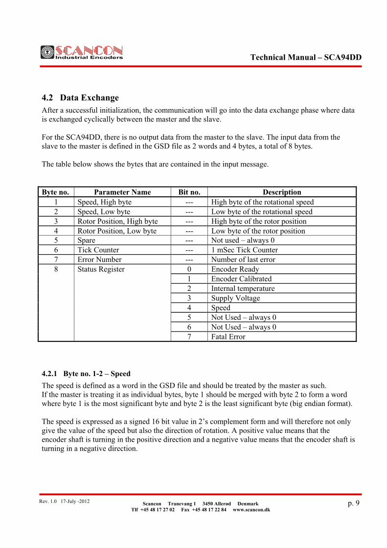
4.2 Data Exchange
After a successful initialization, the communication will go into the data exchange phase where data is exchanged cyclically between the master and the slave. For the SCA94DD, there is no output data from the master to the slave. The input data from the slave to the master is defined in the GSD file as 2 words and 4 bytes, a total of 8 bytes. The table below shows the bytes that are contained in the input message. Byte no. Parameter Name Bit no. Description
1 Speed, High byte --- High byte of the rotational speed 2 Speed, Low byte --- Low byte of the rotational speed 3 Rotor Position, High byte --- High byte of the rotor position 4 Rotor Position, Low byte --- Low byte of the rotor position 5 Spare --- Not used – always 0 6 Tick Counter --- 1 mSec Tick Counter 7 Error Number --- Number of last error 8 Status Register 0 Encoder Ready
1 Encoder Calibrated 2 Internal temperature 3 Supply Voltage 4 Speed 5 Not Used – always 0 6 Not Used – always 0 7 Fatal Error
4.2.1 Byte no. 1-2 – Speed
The speed is defined as a word in the GSD file and should be treated by the master as such. If the master is treating it as individual bytes, byte 1 should be merged with byte 2 to form a word where byte 1 is the most significant byte and byte 2 is the least significant byte (big endian format). The speed is expressed as a signed 16 bit value in 2’s complement form and will therefore not only give the value of the speed but also the direction of rotation. A positive value means that the encoder shaft is turning in the positive direction and a negative value means that the encoder shaft is turning in a negative direction.

Technical Manual – SCA94DD
Scancon Tranevang 1 3450 Allerød Denmark Tlf +45 48 17 27 02 Fax +45 48 17 22 84 www.scancon.dk
p. 10Rev. 1.0 17-July -2012
NOTICE that the definition of positive and negative direction is governed by the value of the “Counting Direction” bit, see Section 4.1.4 above. The resolution of the speed is 0.01 rpm. A speed of 10.00 rpm will therefore be reported as 1000. 4.2.2 Byte no. 3-4 – Rotor Position
The rotor position is defined as a word in the GSD file and should be treated by the master as such. If the master is treating it as individual bytes, byte 3 should be merged with byte 4 to form a word where byte 3 is the most significant byte and byte 4 is the least significant byte (big endian format). The position is expressed as a signed 16 bit value in 2’s complement form and though the position ideally should never be negative it cannot be guaranteed that the position will not in very rare occasions be negative with a low value (-1). If the master does not interpret this correctly it may lead to incorrect functioning. NOTICE that the definition of positive and negative direction is governed by the value of the “Counting Direction” bit, see Section 4.1.4 above. A prerequisite for reporting the correct rotor position is that the internal index pulse of the encoder is aligned with the 0° position of the rotor, see Section 3.2 above and Section 4.2.6 below. The resolution of the rotor position is 0.1° (degree). A position of 180.0° will therefore be reported as 1800. 4.2.3 Byte no. 5 – Spare
This byte is not used for the moment but is for future use. The byte is always send as 0. 4.2.4 Byte no. 6 – Tick Counter
The tick counter is incremented every millisecond and should be used by the master as the “heart beat” of the slave that indicates that the slave is alive and updating the values in the input data periodically. The tick counter can be used by simply detecting that the tick count is different between two consecutive messages. Two precautions must though be taken if using the tick counter this way:
1. The internal cycle time of the master for reading input data must not be lower than 1 mSec.
2. There must not be more than 255 mSec between two consecutive readings. Other strategies may be possible for the use of the tick counter.

Technical Manual – SCA94DD
Scancon Tranevang 1 3450 Allerød Denmark Tlf +45 48 17 27 02 Fax +45 48 17 22 84 www.scancon.dk
p. 11Rev. 1.0 17-July -2012
4.2.5 Byte no. 7 – Error Number
There are not defined any error numbers in this version of the SCA94DD. This byte is always send as 0. 4.2.6 Byte no. 8 – Status Register
The status register gives the immediate status of selected conditions of the SCA94DD. It should be noted that if any of the error bits, bit 2, 3, 4 and bit 7 are set, reliable operation of the encoder cannot be guaranteed. Bit no. 0 – Encoder Ready Bit 0 = 0 (off) – The encoder is not ready – values are not valid Bit 0 = 1 (on) – The encoder is ready – values are valid Bit no. 1 – Encoder Calibrated Bit 1 = 0 (off) – Encoder has not calibrated itself Bit 1 = 1 (on) – Encoder has detected the index point and has calibrated itself Bit no. 2 – Internal Temperature Bit 2 = 0 (off) – Internal temperature is below max. limit Bit 2 = 1 (on) – Internal temperature is too high (> 85°C) Bit no. 3 – Supply Voltage Bit 3 = 0 (off) – Supply voltage is above min. limit Bit 3 = 1 (on) – Supply voltage is too low (< 9VDC) Bit no. 4 – Speed Bit 4 = 0 (off) – Speed is below max. limit Bit 4 = 1 (on) – Speed is too high (> 50 rpm) Bit no. 7 – Fatal Error Bit 7 = 0 (off) – No fatal errors are detected Bit 7 = 1 (on) – A fatal error has been detected There are not defined any fatal errors in this version of the SCA94DD. This bit is always send as 0.
Technical Manual – SCA94DD
Scancon Tranevang 1 3450 Allerød Denmark Tlf +45 48 17 27 02 Fax +45 48 17 22 84 www.scancon.dk
p. 12Rev. 1.0 17-July -2012
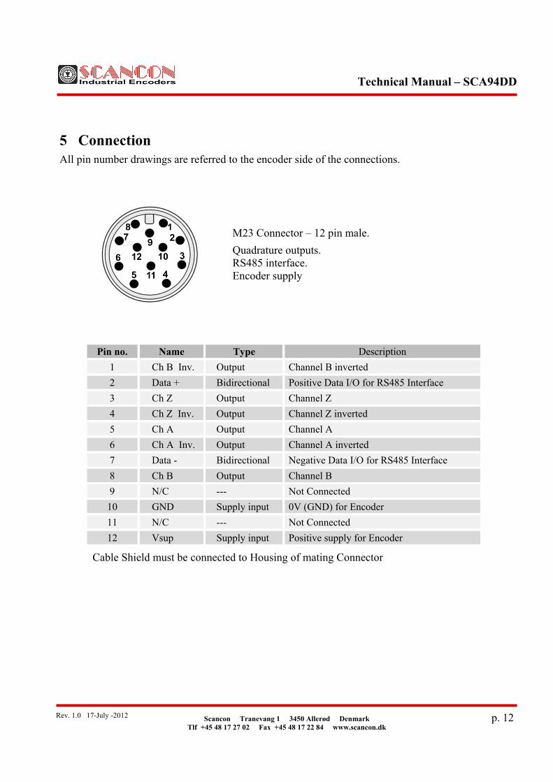
5 Connection
All pin number drawings are referred to the encoder side of the connections.
Pin no. Name Type Description
1 Ch B Inv. Output Channel B inverted
2 Data + Bidirectional Positive Data I/O for RS485 Interface
3 Ch Z Output Channel Z
4 Ch Z Inv. Output Channel Z inverted
5 Ch A Output Channel A
6 Ch A Inv. Output Channel A inverted
7 Data - Bidirectional Negative Data I/O for RS485 Interface
8 Ch B Output Channel B
9 N/C --- Not Connected
10 GND Supply input 0V (GND) for Encoder
11 N/C --- Not Connected
12 Vsup Supply input Positive supply for Encoder
Cable Shield must be connected to Housing of mating Connector
M23 Connector – 12 pin male.
Quadrature outputs. RS485 interface. Encoder supply

Technical Manual – SCA94DD
Scancon Tranevang 1 3450 Allerød Denmark Tlf +45 48 17 27 02 Fax +45 48 17 22 84 www.scancon.dk
p. 13Rev. 1.0 17-July -2012
Pin no. Name Type Description
1 N/C --- Not Connected
2 Line A Bidirectional Negative Data I/O for Profibus Interface
3 N/C --- Not Connected
4 Line B Bidirectional Positive Data I/O for Profibus Interface
5 N/C --- Not Connected
Cable Shield must be connected to Housing of mating Connector
Pin no. Name Type Description
1 N/C --- Not Connected
2 Line A Bidirectional Negative Data I/O for Profibus Interface
3 N/C --- Not Connected
4 Line B Bidirectional Positive Data I/O for Profibus Interface
5 N/C --- Not Connected
Cable Shield must be connected to Housing of mating Connector
M12 Connector – 5 pin male – B coding.
Profibus in.
M12 Connector – 5 pin female – B coding.
Profibus out.

Technical Manual – SCA94DD
Scancon Tranevang 1 3450 Allerød Denmark Tlf +45 48 17 27 02 Fax +45 48 17 22 84 www.scancon.dk
p. 14Rev. 1.0 17-July -2012
6 Mechanical Dimensions
Dimensions in mm.

Technical Manual – SCA94DD
Scancon Tranevang 1 3450 Allerød Denmark Tlf +45 48 17 27 02 Fax +45 48 17 22 84 www.scancon.dk
p. 15Rev. 1.0 17-July -2012
7 Technical Specifications
General Specifications Encoder Type: SCA94DD (Ø94mm.). Supply Voltage: 9 – 30VDC
Current Consumption: (typical without load)
Depending on supply voltage. 100 mA @ Vsup = 10V 60 mA @ Vsup = 24V
Internal Resolution: 1,048,576 (2^20) positions per revolution
Outputs: Quadrature outputs
Interfaces: Profibus for data interchange. RS485 for set-up.
Quadrature Outputs
Outputs Driver: OL7272 Line Driver. HTL compatible. Short circuit protected.
Output Protection: Transient Suppression Module (TSM). Output Current: 40 mA max. per output channel.
Output Format: Two Channel (A,B) quadrature with index (Z) and complementary (A-, B-, Z-) outputs.
Phase Sense: Selectable as clockwise (CW) or counterclockwise (CCW) seen from the shaft end of the encoder.
Resolution: Selectable as 1024, 2048, 4096 or 8192 pulses per revolution.
Maximum Frequency: 25 kHz. Speed Maximum Rotational Speed: 50 rpm Speed Resolution: 0.01 rpm Speed Accuracy:
Depending on sample time. ±0.05 rpm @ sample time = 10 mSec.
Sample Time for Speed: Selectable 1 – 100 mSec. (10 – 1000 samples per second).

Technical Manual – SCA94DD
Scancon Tranevang 1 3450 Allerød Denmark Tlf +45 48 17 27 02 Fax +45 48 17 22 84 www.scancon.dk
p. 16Rev. 1.0 17-July -2012
Rotor Position Rotor Position Resolution: 0.1 deg. Rotor Position Accuracy: ±0.1 deg. Profibus Interface Interface Standard: DP-V0
Baud Rate: All standard baud rates from 9,600 baud to 12 Mbaud
Address Range: 1 - 125 RS485 Interface Communication Parameters: 8 databit, no parity, 1 stop bit.
Baud Rate: All common baud rates from 19,200 baud 921,600 baud.
Protocol: eCODE-ASCII Mechanical Specifications
Material: Housing: Aluminum Cap: Aluminum Shaft: Stainless Steel (AISI 303)
Weight: Encoder: approx. 1100 gr. (38.80 oz) Bearing Life: > 1.9 x 10¹⁰ revolutions at rated load Starting Torque: < 0.1 Nm (14.16 oz-in) at 25° C Mass Moment of Inertia: 31 gcm² (4,39 x 10⁻⁴ oz-in-sec²)
Shaft Loads: Axial 200 N (45 lbs) max. Radial 400 N (90 lbs) max.
Enviromental SpecificationsOperating Temperature: -40° to +85° C Storage Temperature: -40° to +85° C Humidity: 98% RH without condensation Enclosure Rating: IP67 / Nema 6 (approx.) Connection Options
Connectors: 12-pin M23 Male connector 5-pin M12 Male connector 5-pin M12 Female connector