Embed Size (px)
Citation preview
May 2014
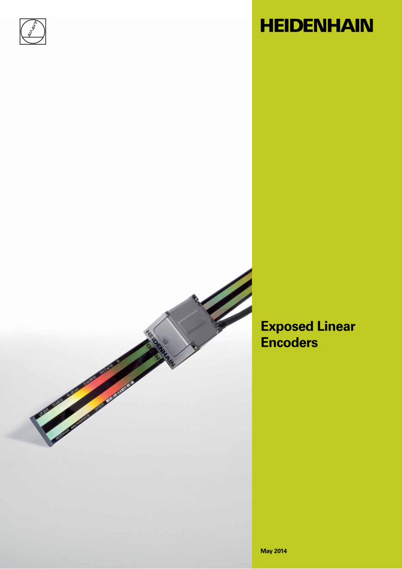
Exposed Linear Encoders
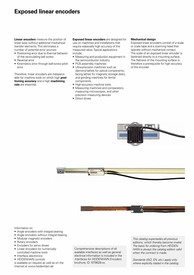
Exposed linear encoders
Linear encoders measure the position of linear axes without additional mechanical transfer elements. This eliminates a number of potential error sources:• Positioning error due to thermal behavior
of the recirculating ball screw• Reversal error• Kinematics error through ball-screw pitch
error
Therefore, linear encoders are indispens-able for machine tools on which high posi-tioning accuracy and a high machining rate are essential.
Exposed linear encoders are designed for use on machines and installations that require especially high accuracy of the measured value. Typical applications include:• Measuring and production equipment in
the semiconductor industry• PCB assembly machines• Ultra-precision machines such as
diamond lathes for optical components, facing lathes for magnetic storage disks, and grinding machines for ferrite components
• High-accuracy machine tools• Measuring machines and comparators,
measuring microscopes, and other precision measuring devices
• Direct drives
Mechanical designExposed linear encoders consist of a scale or scale tape and a scanning head that operate without mechanical contact.The scale of an exposed linear encoder is fastened directly to a mounting surface. The fl atness of the mounting surface is therefore a prerequisite for high accuracy of the encoder.
Information on• Angle encoders with integral bearing• Angle encoders without integral bearing• Modular magnetic encoders• Rotary encoders• Encoders for servo drives• Linear encoders for numerically
controlled machine tools• Interface electronics• HEIDENHAIN controlsis available on request as well as on the Internet at www.heidenhain.de
This catalog supersedes all previous editions, which thereby become invalid.The basis for ordering from HEIDEN-HAIN is always the catalog edition valid when the contract is made.
Standards (ISO, EN, etc.) apply only where explicitly stated in the catalog.
Comprehensive descriptions of all available interfaces as well as general electrical information is included in the Interfaces for HEIDENHAIN Encoders brochure, ID 1078628-xx.
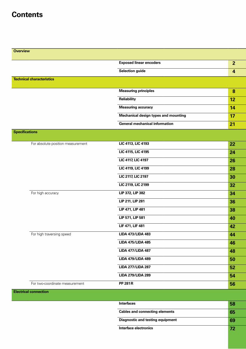
Overview
Exposed linear encoders 2
Selection guide 4
Technical characteristics
Measuring principles 8
Reliability 12
Measuring accuracy 14
Mechanical design types and mounting 17
General mechanical information 21
Specifications
For absolute position measurement LIC 4113, LIC 4193 22
LIC 4115, LIC 4195 24
LIC 4117, LIC 4197 26
LIC 4119, LIC 4199 28
LIC 2117, LIC 2197 30
LIC 2119, LIC 2199 32
For high accuracy LIP 372, LIP 382 34
LIP 211, LIP 281 36
LIP 471, LIP 481 38
LIP 571, LIP 581 40
LIF 471, LIF 481 42
For high traversing speed LIDA 473/LIDA 483 44
LIDA 475/LIDA 485 46
LIDA 477/LIDA 487 48
LIDA 479/LIDA 489 50
LIDA 277/LIDA 287 52
LIDA 279/LIDA 289 54
For two-coordinate measurement PP 281 R 56
Electrical connection
Interfaces 58
Cables and connecting elements 65
Diagnostic and testing equipment 69
Interface electronics 72
Contents
4
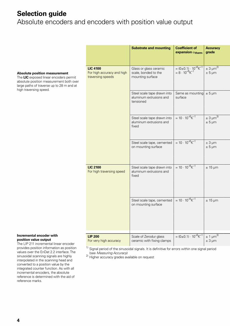
Selection guideAbsolute encoders and encoders with position value output
Absolute position measurementThe LIC exposed linear encoders permit absolute position measurement both over large paths of traverse up to 28 m and at high traversing speed.
Substrate and mounting Coefficient of expansion atherm
Accuracy grade
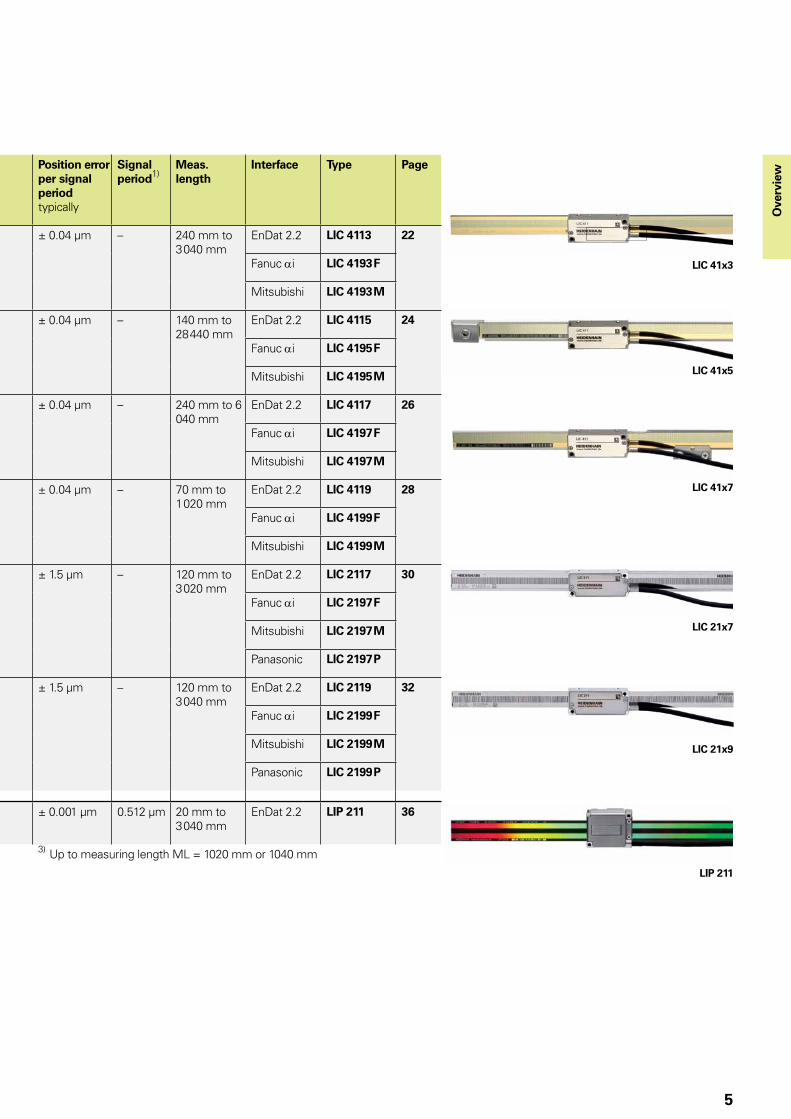
Position error per signal period typically
Signal period1)
Meas. length
Interface Type Page
LIC 4100For high accuracy and high traversing speeds
Glass or glass ceramic scale, bonded to the mounting surface
� (0±0.1) · 10–6K–1 � 8 · 10–6K–1
± 3 µm2)
± 5 µm± 0.04 µm – 240 mm to
3 040 mmEnDat 2.2 LIC 4113 22
Fanuc ai LIC 4193 F
Mitsubishi LIC 4193 M
Steel scale tape drawn into aluminum extrusions and tensioned
Same as mounting surface
± 5 µm ± 0.04 µm – 140 mm to 28 440 mm
EnDat 2.2 LIC 4115 24
Fanuc ai LIC 4195 F
Mitsubishi LIC 4195 M
Steel scale tape drawn into aluminum extrusions and fixed
� 10 · 10–6K–1 ± 3 µm3)
± 5 µm± 0.04 µm – 240 mm to 6
040 mmEnDat 2.2 LIC 4117 26
Fanuc ai LIC 4197 F
Mitsubishi LIC 4197 M
Steel scale tape, cemented on mounting surface
� 10 · 10–6K–1 ± 3 µm± 5 µm
± 0.04 µm – 70 mm to 1 020 mm
EnDat 2.2 LIC 4119 28
Fanuc ai LIC 4199 F
Mitsubishi LIC 4199 M
LIC 2100For high traversing speed
Steel scale tape drawn into aluminum extrusions and fixed
� 10 · 10–6K–1 ± 15 µm ± 1.5 µm – 120 mm to 3 020 mm
EnDat 2.2 LIC 2117 30
Fanuc ai LIC 2197 F
Mitsubishi LIC 2197 M
Panasonic LIC 2197 P
Steel scale tape, cemented on mounting surface
� 10 · 10–6K–1 ± 15 µm ± 1.5 µm – 120 mm to 3 040 mm
EnDat 2.2 LIC 2119 32
Fanuc ai LIC 2199 F
Mitsubishi LIC 2199 M
Panasonic LIC 2199 P
LIP 200For very high accuracy
Scale of Zerodur glass ceramic with fixing clamps
� (0±0.1) · 10–6K–1 ± 1 µm3)
± 3 µm± 0.001 µm 0.512 µm 20 mm to
3 040 mmEnDat 2.2 LIP 211 36
1) Signal period of the sinusoidal signals. It is definitive for errors within one signal period (see Measuring Accuracy)
2) Higher accuracy grades available on request
3) Up to measuring length ML = 1020 mm or 1040 mm
Incremental encoder with position value outputThe LIP 211 incremental linear encoder provides position information as position values over the EnDat 2.2 interface. The sinusoidal scanning signals are highly interpolated in the scanning head and converted to a position value by the integrated counter function. As with all incremental encoders, the absolute reference is determined with the aid of reference marks.
LIC 41x3
LIC 41x5
LIC 41x7
LIC 21x7
LIC 21x9
LIP 211
5
Substrate and mounting Coefficient of expansion atherm
Accuracy grade
Position error per signal period typically
Signal period1)
Meas. length
Interface Type Page
LIC 4100For high accuracy and high traversing speeds
Glass or glass ceramic scale, bonded to the mounting surface
� (0±0.1) · 10–6K–1 � 8 · 10–6K–1
± 3 µm2)
± 5 µm± 0.04 µm – 240 mm to
3 040 mmEnDat 2.2 LIC 4113 22
Fanuc ai LIC 4193 F
Mitsubishi LIC 4193 M
Steel scale tape drawn into aluminum extrusions and tensioned
Same as mounting surface
± 5 µm ± 0.04 µm – 140 mm to 28 440 mm
EnDat 2.2 LIC 4115 24
Fanuc ai LIC 4195 F
Mitsubishi LIC 4195 M
Steel scale tape drawn into aluminum extrusions and fixed
� 10 · 10–6K–1 ± 3 µm3)
± 5 µm± 0.04 µm – 240 mm to 6
040 mmEnDat 2.2 LIC 4117 26
Fanuc ai LIC 4197 F
Mitsubishi LIC 4197 M
Steel scale tape, cemented on mounting surface
� 10 · 10–6K–1 ± 3 µm± 5 µm
± 0.04 µm – 70 mm to 1 020 mm
EnDat 2.2 LIC 4119 28
Fanuc ai LIC 4199 F
Mitsubishi LIC 4199 M
LIC 2100For high traversing speed
Steel scale tape drawn into aluminum extrusions and fixed
� 10 · 10–6K–1 ± 15 µm ± 1.5 µm – 120 mm to 3 020 mm
EnDat 2.2 LIC 2117 30
Fanuc ai LIC 2197 F
Mitsubishi LIC 2197 M
Panasonic LIC 2197 P
Steel scale tape, cemented on mounting surface
� 10 · 10–6K–1 ± 15 µm ± 1.5 µm – 120 mm to 3 040 mm
EnDat 2.2 LIC 2119 32
Fanuc ai LIC 2199 F
Mitsubishi LIC 2199 M
Panasonic LIC 2199 P
LIP 200For very high accuracy
Scale of Zerodur glass ceramic with fixing clamps
� (0±0.1) · 10–6K–1 ± 1 µm3)
± 3 µm± 0.001 µm 0.512 µm 20 mm to
3 040 mmEnDat 2.2 LIP 211 36
1) Signal period of the sinusoidal signals. It is definitive for errors within one signal period (see Measuring Accuracy)
2) Higher accuracy grades available on request
3) Up to measuring length ML = 1020 mm or 1040 mm
Ove
rvie
w
6
Selection guideIncremental encoders
Substrate and mounting Coefficient of expansion atherm
Accuracy grade
Position error per signal period typ.
Signal period1)
Meas. length
Interface Type Page
LIPFor very high accuracy
Zerodur glass ceramic embedded in bolted-on Invar carrier
� 0 · 10–6K–1 ± 0.5 µm3) ± 0.001 µm 0.128 µm 70 mm to 270 mm
« TTL LIP 372 34
» 1 VPP LIP 382
Scale of Zerodur glass ceramic with fixing clamps
� 0 · 10–6K–1 ± 1 µm± 3 µm
± 0.001 µm 0.512 µm 20 mm to 3 040 mm
» 1 VPP LIP 281 36
EnDat 2.2 LIP 211
Scale of Zerodur glass ceramic or glass with fixing clamps
� 0 · 10–6K–1 or � 8 · 10–6K–1
± 0.5 µm± 1 µm3)
± 0.02 µm 2 µm 70 mm to 420 mm
« TTL LIP 471 38
» 1 VPP LIP 481
Glass scale, fixed with clamps � 8 · 10–6K–1 ± 1 µm ± 0.04 µm 4 µm 70 mm to 1 440 mm
« TTL LIP 571 40
» 1 VPP LIP 581
LIFFor high accuracy
Scale of Zerodur glass ceramic or glass, cemented with PRECIMET adhesive film
� 0 · 10–6K–1 or � 8 · 10–6K–1
± 1 µm5)
± 3 µm± 0.04 µm 4 µm 70 mm to
1 020 mm4) « TTL LIF 471 42
» 1 VPP LIF 481
LIDAFor high traversing speeds and large measuring lengths
Glass or glass ceramic scale, bonded to the mounting surface
� 0 · 10–6K–1 or � 8 · 10–6K–1
± 1 µm5)
± 3 µm ± 5 µm
± 0.2 µm 20 µm 240 mm to 3 040 mm
« TTL LIDA 473 44
» 1 VPP LIDA 483
Steel scale tape drawn into aluminum extrusions and tensioned
Same as mounting surface
± 5 µm ± 0.2 µm 20 µm 140 mm to 30 040 mm
« TTL LIDA 475 46
» 1 VPP LIDA 485
Steel scale tape drawn into aluminum extrusions and fixed
� 10 · 10–6K–1 ± 3 µm2)
± 5 µm± 15 µm6)
± 0.2 µm 20 µm 240 mm to 6 040 mm
« TTL LIDA 477 48
» 1 VPP LIDA 487 high speed
Steel scale tape, cemented on mounting surface
� 10 · 10–6K–1 ± 3 µm2)
± 15 µm6)± 0.2 µm 20 µm Up to
6 000 mm4)« TTL LIDA 479 50
» 1 VPP LIDA 489
Steel scale tape drawn into aluminum extrusions and fixed
� 10 · 10–6K–1 ± 15 µm ± 2 µm 200 µm Up to 10 000 mm4)
« TTL LIDA 277 52
» 1 VPP LIDA 287
Steel scale tape, cemented on mounting surface
� 10 · 10–6K–1 ± 15 µm ± 2 µm 200 µm Up to 10 000 mm4)
« TTL LIDA 279 54
» 1 VPP LIDA 289
PPFor two-coordinate measurement
Glass grid plate, with full-surface bonding
� 8 · 10–6K–1 ± 2 µm ± 0.04 µm 4 µm Measuring range 68 x 68 mm4)
» 1 VPP PP 281 56
LIP/LIFFor application in high and ultrahigh vacuum technology
Scale of Zerodur glass ceramic or glass with fixing clamps
� 0 · 10–6K–1 or � 8 · 10–6K–1
± 0.5 µm± 1 µm
± 0.02 µm 2 µm 70 mm to 420 mm
» 1 VPP LIP 481 V LIP 481 U
Prod-uct info
± 3 µm ± 0.04 µm 4 µm 70 mm to 1 020 mm
LIF 481 V
1) Signal period of the sinusoidal signals. It is definitive for errors within one signal period (see Measuring Accuracy)
2) Up to measuring lengths 1 020 mm or 1 040 mm3) Higher accuracy grades available on request
4) Other measuring lengths/ranges upon request5) Only for Zerodur glass ceramics, with LIDA 4x3 up to ML 1640 mm6) ± 5 µm after linear length-error compensation in the subsequent
electronics
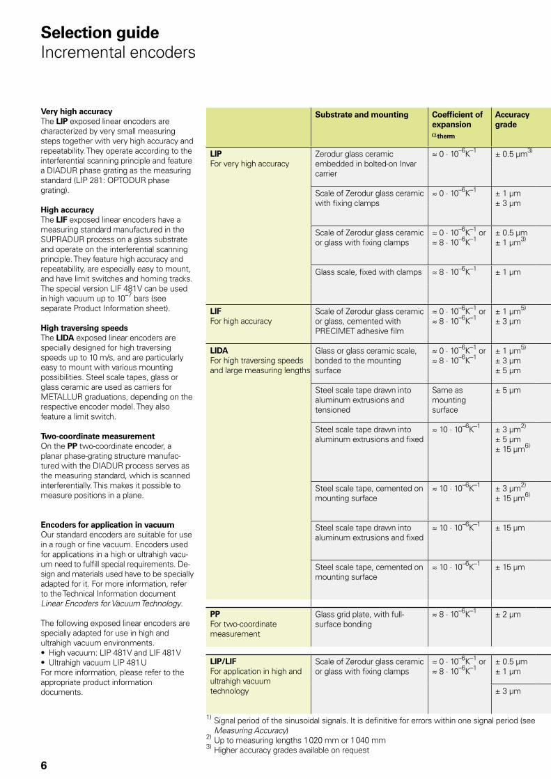
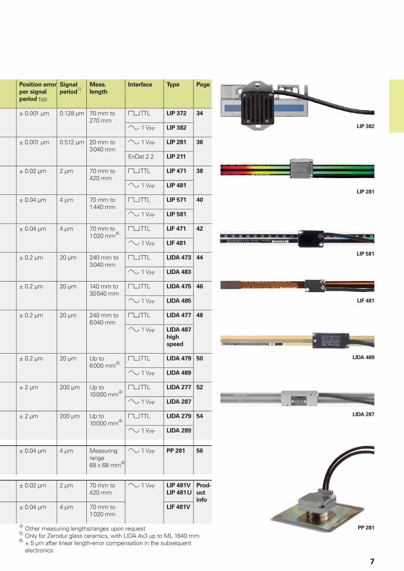
Very high accuracyThe LIP exposed linear encoders are characterized by very small measuring steps together with very high accuracy and repeatability. They operate according to the interferential scanning principle and feature a DIADUR phase grating as the measuring standard (LIP 281: OPTODUR phase grating).
High accuracyThe LIF exposed linear encoders have a measuring standard manufactured in the SUPRADUR process on a glass substrate and operate on the interferential scanning principle. They feature high accuracy and repeatability, are especially easy to mount, and have limit switches and homing tracks. The special version LIF 481 V can be used in high vacuum up to 10–7 bars (see separate Product Information sheet).
High traversing speedsThe LIDA exposed linear encoders are specially designed for high traversing speeds up to 10 m/s, and are particularly easy to mount with various mounting possibilities. Steel scale tapes, glass or glass ceramic are used as carriers for METALLUR graduations, depending on the respective encoder model. They also feature a limit switch.
Two-coordinate measurementOn the PP two-coordinate encoder, a planar phase-grating structure manufac-tured with the DIADUR process serves as the measuring standard, which is scanned interferentially. This makes it possible to measure positions in a plane.
Encoders for application in vacuumOur standard encoders are suitable for use in a rough or fine vacuum. Encoders used for applications in a high or ultrahigh vacu-um need to fulfill special requirements. De-sign and materials used have to be specially adapted for it. For more information, refer to the Technical Information document Linear Encoders for Vacuum Technology.
The following exposed linear encoders are specially adapted for use in high and ultrahigh vacuum environments.• High vacuum: LIP 481 V and LIF 481 V• Ultrahigh vacuum LIP 481 UFor more information, please refer to the appropriate product information documents.
LIF 481
LIP 581
PP 281
LIDA 489
LIDA 287
LIP 382
LIP 281
7
Position error
per signal
period typ.
Signal
period1)
Meas.
length
Interface Type Page
± 0.001 µm 0.128 µm 70 mm to 270 mm
TTL LIP 372 34
1 VPP LIP 382
± 0.001 µm 0.512 µm 20 mm to 3 040 mm
1 VPP LIP 281 36
EnDat 2.2 LIP 211
± 0.02 µm 2 µm 70 mm to 420 mm
TTL LIP 471 38
1 VPP LIP 481
± 0.04 µm 4 µm 70 mm to 1 440 mm
TTL LIP 571 40
1 VPP LIP 581
± 0.04 µm 4 µm 70 mm to 1 020 mm4)
TTL LIF 471 42
1 VPP LIF 481
± 0.2 µm 20 µm 240 mm to 3 040 mm
TTL LIDA 473 44
1 VPP LIDA 483
± 0.2 µm 20 µm 140 mm to 30 040 mm
TTL LIDA 475 46
1 VPP LIDA 485
± 0.2 µm 20 µm 240 mm to 6 040 mm
TTL LIDA 477 48
1 VPP LIDA 487
high
speed
± 0.2 µm 20 µm Up to 6 000 mm4)
TTL LIDA 479 50
1 VPP LIDA 489
± 2 µm 200 µm Up to 10 000 mm4)
TTL LIDA 277 52
1 VPP LIDA 287
± 2 µm 200 µm Up to 10 000 mm4)
TTL LIDA 279 54
1 VPP LIDA 289
± 0.04 µm 4 µm Measuring range 68 x 68 mm4)
1 VPP PP 281 56
± 0.02 µm 2 µm 70 mm to 420 mm
1 VPP LIP 481 V
LIP 481 U
Prod-
uct
info
± 0.04 µm 4 µm 70 mm to 1 020 mm
LIF 481 V
4) Other measuring lengths/ranges upon request5) Only for Zerodur glass ceramics, with LIDA 4x3 up to ML 1640 mm6) ± 5 µm after linear length-error compensation in the subsequent
electronics
8
Measuring principlesMeasuring standard
HEIDENHAIN encoders with optical scanning incorporate measuring standards of periodic structures known as graduations.
These graduations are applied to a carrier substrate of glass or steel. The scale substrate for large measuring lengths is a steel tape.
HEIDENHAIN manufactures the precision graduations in specially developed, photolithographic processes.• AURODUR: matte-etched lines on gold-
plated steel tape with typical graduation period of 40 µm
• METALLUR: contamination-tolerant graduation of metal lines on gold, with typical graduation period of 20 µm
• DIADUR: extremely robust chromium lines on glass (typical graduation period of 20 µm) or three-dimensional chromium structures (typical graduation period of 8 µm) on glass
• SUPRADUR phase grating: optically three dimensional, planar structure; particularly tolerant to contamination; typical graduation period of 8 µm and fi ner
• OPTODUR phase grating: optically three dimensional, planar structure with particularly high refl ectance, typical graduation period of 2 µm and less
Along with these very fi ne grating periods, these processes permit a high defi nition and homogeneity of the line edges. Together with the photoelectric scanning method, this high edge defi nition is a precondition for the high quality of the output signals.
The master graduations are manufactured by HEIDENHAIN on custom-built high-precision dividing engines.
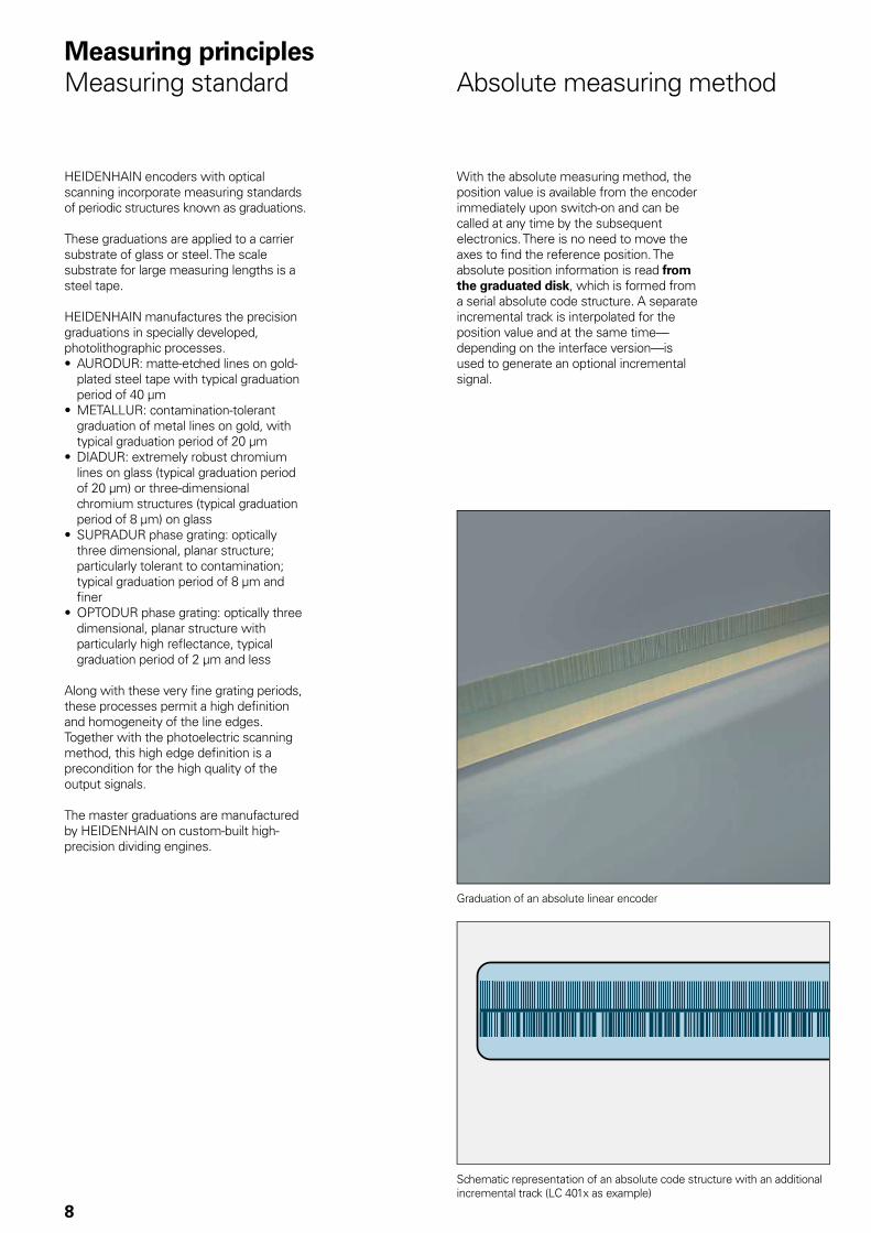
Absolute measuring method
With the absolute measuring method, the position value is available from the encoder immediately upon switch-on and can be called at any time by the subsequent electronics. There is no need to move the axes to fi nd the reference position. The absolute position information is read from the graduated disk, which is formed from a serial absolute code structure. A separate incremental track is interpolated for the position value and at the same time—depending on the interface version—is used to generate an optional incremental signal.
Schematic representation of an absolute code structure with an additional incremental track (LC 401x as example)
Graduation of an absolute linear encoder
9
Tech
nic
al c
har
acte
rist
ics
Incremental measuring method
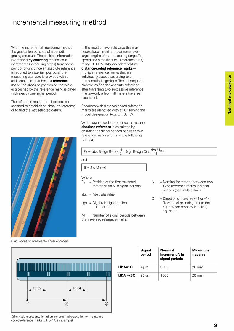
With the incremental measuring method, the graduation consists of a periodic grating structure. The position information is obtained by counting the individual increments (measuring steps) from some point of origin. Since an absolute reference is required to ascertain positions, the measuring standard is provided with an additional track that bears a reference mark. The absolute position on the scale, established by the reference mark, is gated with exactly one signal period.
The reference mark must therefore be scanned to establish an absolute reference or to fi nd the last selected datum.
In the most unfavorable case this may necessitate machine movements over large lengths of the measuring range. To speed and simplify such “reference runs,” many HEIDENHAIN encoders feature distance-coded reference marks—multiple reference marks that are individually spaced according to a mathematical algorithm. The subsequent electronics fi nd the absolute reference after traversing two successive reference marks—only a few millimeters traverse (see table).
Encoders with distance-coded reference marks are identifi ed with a “C” behind the model designation (e.g. LIP 581 C).
With distance-coded reference marks, the absolute reference is calculated by counting the signal periods between two reference marks and using the following formula:
and
P1 = (abs B–sgn B–1) x N + (sgn B–sgn D) x abs MRR2 2
B = 2 x MRR–G
Where:P1 = Position of the fi rst traversed
reference mark in signal periods
abs = Absolute value
sgn = Algebraic sign function (“+1” or “–1”)
MRR = Number of signal periods between the traversed reference marks
N = Nominal increment between two fi xed reference marks in signal periods (see table below)
D = Direction of traverse (+1 or –1). Traverse of scanning unit to the right (when properly installed) equals +1.
Graduations of incremental linear encoders
Schematic representation of an incremental graduation with distance-coded reference marks (LIP 5x1 C as example)
Signal period
Nominal increment N in signal periods
Maximum traverse
LIP 5x1 C 4 µm 5 000 20 mm
LIDA 4x3 C 20 µm 1 000 20 mm
10
Photoelectric scanning
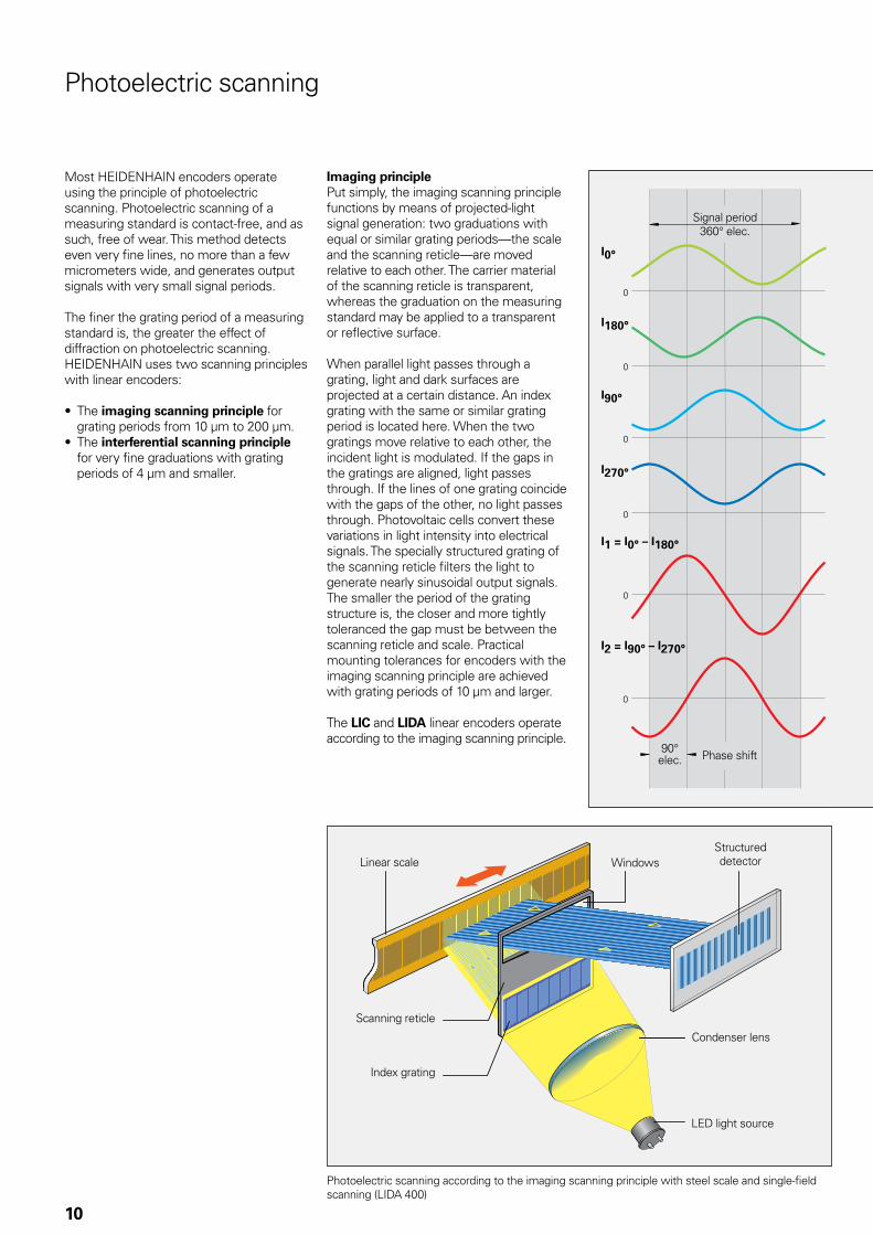
Most HEIDENHAIN encoders operate using the principle of photoelectric scanning. Photoelectric scanning of a measuring standard is contact-free, and as such, free of wear. This method detects even very fine lines, no more than a few micrometers wide, and generates output signals with very small signal periods.
The finer the grating period of a measuring standard is, the greater the effect of diffraction on photoelectric scanning. HEIDENHAIN uses two scanning principles with linear encoders:
• The imaging scanning principle for grating periods from 10 µm to 200 µm.
• The interferential scanning principle for very fine graduations with grating periods of 4 µm and smaller.
Imaging principlePut simply, the imaging scanning principle functions by means of projected-light signal generation: two graduations with equal or similar grating periods—the scale and the scanning reticle—are moved relative to each other. The carrier material of the scanning reticle is transparent, whereas the graduation on the measuring standard may be applied to a transparent or reflective surface.
When parallel light passes through a grating, light and dark surfaces are projected at a certain distance. An index grating with the same or similar grating period is located here. When the two gratings move relative to each other, the incident light is modulated. If the gaps in the gratings are aligned, light passes through. If the lines of one grating coincide with the gaps of the other, no light passes through. Photovoltaic cells convert these variations in light intensity into electrical signals. The specially structured grating of the scanning reticle filters the light to generate nearly sinusoidal output signals. The smaller the period of the grating structure is, the closer and more tightly toleranced the gap must be between the scanning reticle and scale. Practical mounting tolerances for encoders with the imaging scanning principle are achieved with grating periods of 10 µm and larger.
The LIC and LIDA linear encoders operate according to the imaging scanning principle.
Signal period360° elec.
90° elec. Phase shift
Linear scale WindowsStructured detector
Scanning reticle
Index grating
Condenser lens
LED light source
Photoelectric scanning according to the imaging scanning principle with steel scale and single-field scanning (LIDA 400)
11
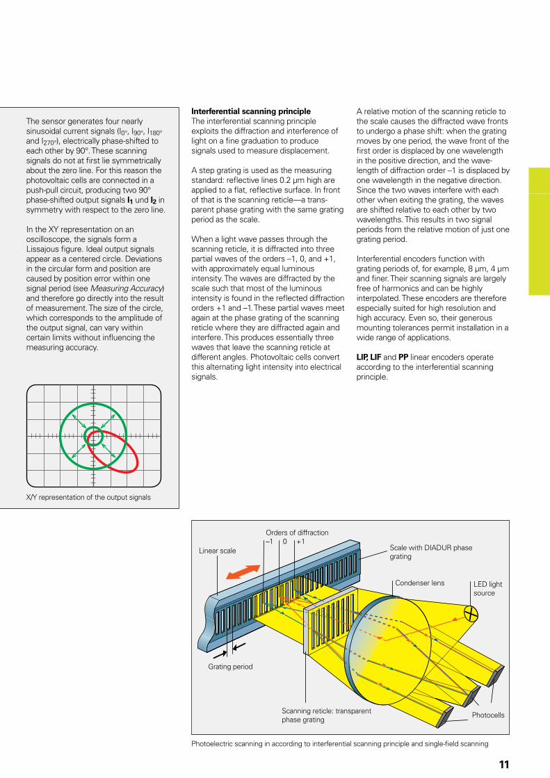
The sensor generates four nearly sinusoidal current signals (I0°, I90°, I180° and I270°), electrically phase-shifted to each other by 90°. These scanning signals do not at first lie symmetrically about the zero line. For this reason the photovoltaic cells are connected in a push-pull circuit, producing two 90° phase-shifted output signals I1 und I2 in symmetry with respect to the zero line.
In the XY representation on an oscilloscope, the signals form a Lissajous figure. Ideal output signals appear as a centered circle. Deviations in the circular form and position are caused by position error within one signal period (see Measuring Accuracy) and therefore go directly into the result of measurement. The size of the circle, which corresponds to the amplitude of the output signal, can vary within certain limits without influencing the measuring accuracy.
Photoelectric scanning in according to interferential scanning principle and single-field scanning
Linear scale
Orders of diffraction–1 0 +1
Scale with DIADUR phase grating
Grating period
Scanning reticle: transparent phase grating
Photocells
LED light source
Condenser lens
Interferential scanning principleThe interferential scanning principle exploits the diffraction and interference of light on a fine graduation to produce signals used to measure displacement.
A step grating is used as the measuring standard: reflective lines 0.2 µm high are applied to a flat, reflective surface. In front of that is the scanning reticle—a trans-parent phase grating with the same grating period as the scale.
When a light wave passes through the scanning reticle, it is diffracted into three partial waves of the orders –1, 0, and +1, with approximately equal luminous intensity. The waves are diffracted by the scale such that most of the luminous intensity is found in the reflected diffraction orders +1 and –1. These partial waves meet again at the phase grating of the scanning reticle where they are diffracted again and interfere. This produces essentially three waves that leave the scanning reticle at different angles. Photovoltaic cells convert this alternating light intensity into electrical signals.
A relative motion of the scanning reticle to the scale causes the diffracted wave fronts to undergo a phase shift: when the grating moves by one period, the wave front of the first order is displaced by one wavelength in the positive direction, and the wave-length of diffraction order –1 is displaced by one wavelength in the negative direction. Since the two waves interfere with each other when exiting the grating, the waves are shifted relative to each other by two wavelengths. This results in two signal periods from the relative motion of just one grating period.
Interferential encoders function with grating periods of, for example, 8 µm, 4 µm and finer. Their scanning signals are largely free of harmonics and can be highly interpolated. These encoders are therefore especially suited for high resolution and high accuracy. Even so, their generous mounting tolerances permit installation in a wide range of applications.
LIP, LIF and PP linear encoders operate according to the interferential scanning principle.
X/Y representation of the output signals
12
Reliability
Exposed linear encoders from HEIDEN-HAIN are optimized for use on fast, precise machines. In spite of the exposed mechan-ical design, they are highly tolerant to contamination, ensure high long-term stability, and are quickly and easily mounted.
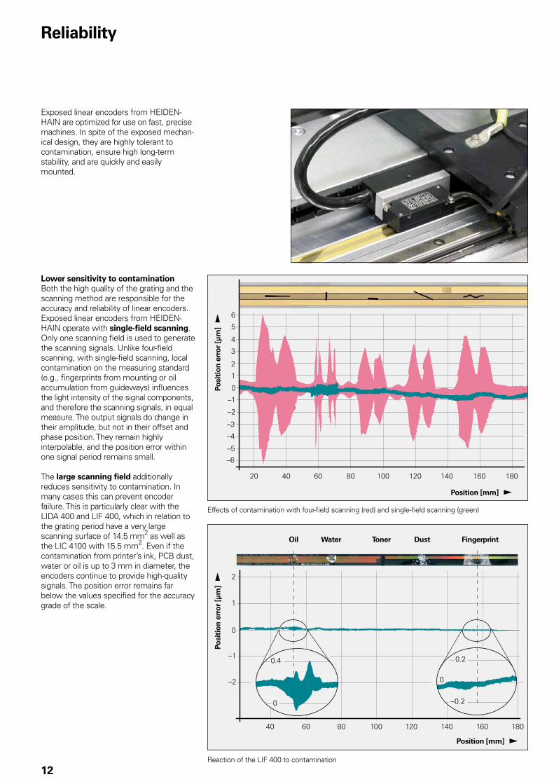
Lower sensitivity to contaminationBoth the high quality of the grating and the scanning method are responsible for the accuracy and reliability of linear encoders. Exposed linear encoders from HEIDEN-HAIN operate with single-field scanning. Only one scanning field is used to generate the scanning signals. Unlike four-field scanning, with single-field scanning, local contamination on the measuring standard (e.g., fingerprints from mounting or oil accumulation from guideways) influences the light intensity of the signal components, and therefore the scanning signals, in equal measure. The output signals do change in their amplitude, but not in their offset and phase position. They remain highly interpolable, and the position error within one signal period remains small.
The large scanning field additionally reduces sensitivity to contamination. In many cases this can prevent encoder failure. This is particularly clear with the LIDA 400 and LIF 400, which in relation to the grating period have a very large scanning surface of 14.5 mm2 as well as the LIC 4100 with 15.5 mm2. Even if the contamination from printer’s ink, PCB dust, water or oil is up to 3 mm in diameter, the encoders continue to provide high-quality signals. The position error remains far below the values specified for the accuracy grade of the scale.
Effects of contamination with four-field scanning (red) and single-field scanning (green)
Reaction of the LIF 400 to contamination
Position [mm]
Position [mm]
Posi
tio
n e
rro
r [µ
m]
Posi
tio
n e
rro
r [µ
m]
Oil Water Toner Dust Fingerprint
13
LIDA 400
LIF 400
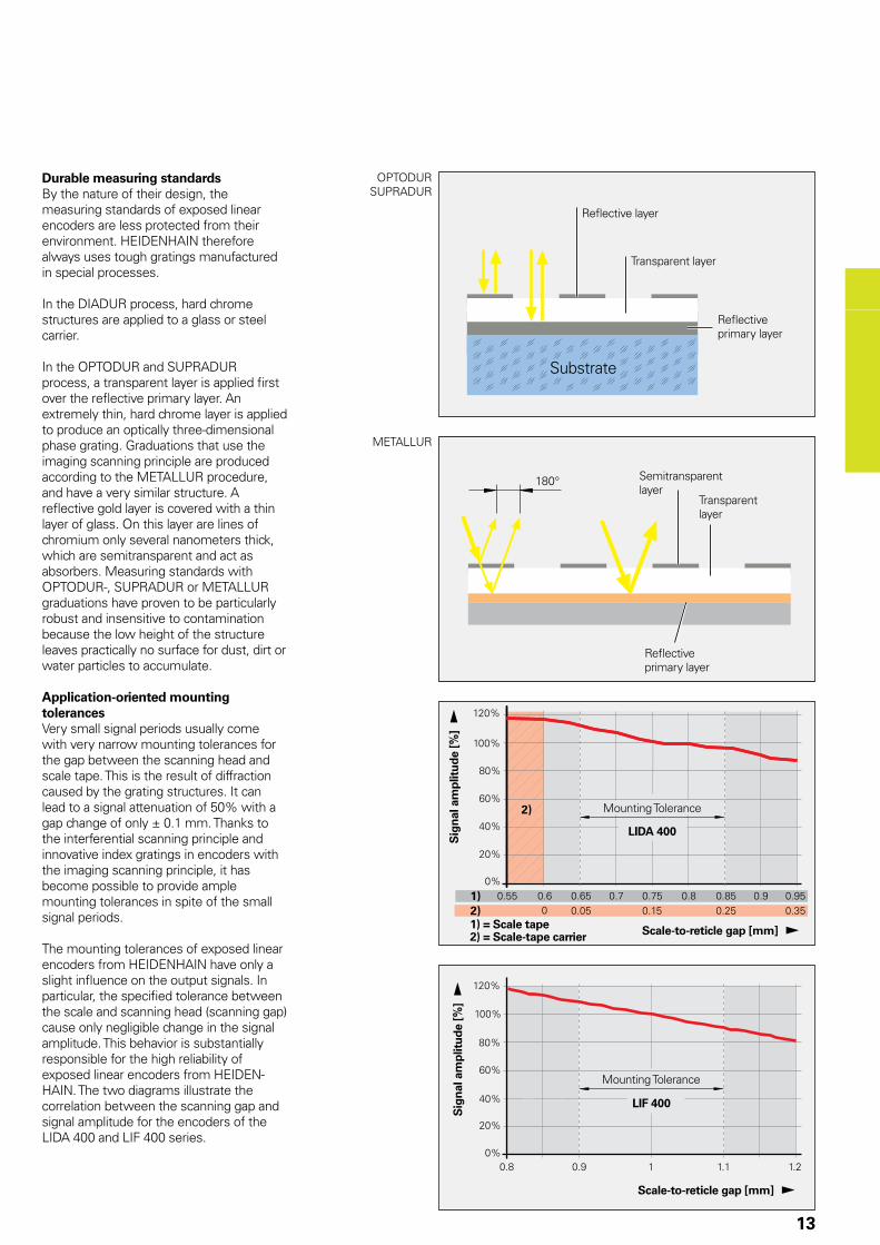
Durable measuring standardsBy the nature of their design, the measuring standards of exposed linear encoders are less protected from their environment. HEIDENHAIN therefore always uses tough gratings manufactured in special processes.
In the DIADUR process, hard chrome structures are applied to a glass or steel carrier.
In the OPTODUR and SUPRADUR process, a transparent layer is applied first over the reflective primary layer. An extremely thin, hard chrome layer is applied to produce an optically three-dimensional phase grating. Graduations that use the imaging scanning principle are produced according to the METALLUR procedure, and have a very similar structure. A reflective gold layer is covered with a thin layer of glass. On this layer are lines of chromium only several nanometers thick, which are semitransparent and act as absorbers. Measuring standards with OPTODUR-, SUPRADUR or METALLUR graduations have proven to be particularly robust and insensitive to contamination because the low height of the structure leaves practically no surface for dust, dirt or water particles to accumulate.
Application-oriented mounting tolerancesVery small signal periods usually come with very narrow mounting tolerances for the gap between the scanning head and scale tape. This is the result of diffraction caused by the grating structures. It can lead to a signal attenuation of 50% with a gap change of only ± 0.1 mm. Thanks to the interferential scanning principle and innovative index gratings in encoders with the imaging scanning principle, it has become possible to provide ample mounting tolerances in spite of the small signal periods.
The mounting tolerances of exposed linear encoders from HEIDENHAIN have only a slight influence on the output signals. In particular, the specified tolerance between the scale and scanning head (scanning gap) cause only negligible change in the signal amplitude. This behavior is substantially responsible for the high reliability of exposed linear encoders from HEIDEN-HAIN. The two diagrams illustrate the correlation between the scanning gap and signal amplitude for the encoders of the LIDA 400 and LIF 400 series.
Reflective layer
Transparent layer
Reflective primary layer
Substrate
OPTODURSUPRADUR
Sig
nal
am
plit
ud
e [%
] S
ign
al a
mp
litu
de
[%]
Scale-to-reticle gap [mm]
Scale-to-reticle gap [mm]
1) = Scale tape2) = Scale-tape carrier
Mounting Tolerance
Mounting Tolerance
METALLUR
Transparent layer
Reflective primary layer
Semitransparent layer
14
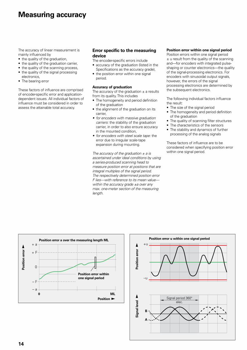
Measuring accuracy
Position error a over the measuring length ML
Position error within one signal period
Posi
tio
n e
rro
r
Posi
tio
n e
rro
r
Sig
nal
leve
l Position Signal period 360° elec.
Position error u within one signal period
The accuracy of linear measurement is mainly influenced by• the quality of the graduation,• the quality of the graduation carrier,• the quality of the scanning process,• the quality of the signal processing
electronics,• The bearing error
These factors of influence are comprised of encoder-specific error and application-dependent issues. All individual factors of influence must be considered in order to assess the attainable total accuracy.
Error specific to the measuring device The encoder-specific errors include• accuracy of the graduation (listed in the
Specifications as the accuracy grade),• the position error within one signal
period.
Accuracy of graduation The accuracy of the graduation ± a results from its quality. This includes• The homogeneity and period definition
of the graduation• the alignment of the graduation on its
carrier,• for encoders with massive graduation
carriers: the stability of the graduation carrier, in order to also ensure accuracy in the mounted condition,
• for encoders with steel scale tape: the error due to irregular scale-tape expansion during mounting.
The accuracy of the graduation ± a is ascertained under ideal conditions by using a series-produced scanning head to measure position error at positions that are integral multiples of the signal period. The respectively determined position error F lies—with reference to its mean value—within the accuracy grade ±a over any max. one-meter section of the measuring length.
Position error within one signal periodPosition errors within one signal period ± u result from the quality of the scanning and—for encoders with integrated pulse-shaping or counter electronics—the quality of the signal-processing electronics. For encoders with sinusoidal output signals, however, the errors of the signal processing electronics are determined by the subsequent electronics.
The following individual factors influence the result:• The size of the signal period• The homogeneity and period definition
of the graduation• The quality of scanning filter structures• The characteristics of the sensors• The stability and dynamics of further
processing of the analog signals
These factors of influence are to be considered when specifying position error within one signal period.

15
Signal period of the scanning signals
Typical position error u within one signal period
LIP 3x2 0.128 µm ± 0.001 µm
LIP 281 0.512 µm ± 0.001 µm
LIP 4x1 2 µm ± 0.02 µm
LIP 5x1LIF, PP
4 µm ± 0.04 µm
LIC 41xx – ± 0.04 µm
LIDA 4xx 20 µm ± 0.2 µm
LIC 21xx – ± 1.5 µm
LIDA 2xx 200 µm ± 2 µm
Position error within one signal period ± u is specified in relation to the signal period. For exposed linear encoders, the value is typically better than ± 1 % of the signal period. You will find the specific values in the following table.
Position errors within one signal period already become apparent in very small paths of traverse and in repeated measurements. They especially lead to fluctuations in traversing speed in the speed control loop.
Application-dependent errorThe mounting and adjustment of the scanning head, in addition to the given encoder-specific error, normally have a significant effect on the accuracy that can be achieved by encoders without integral bearings. The application-dependent error values must be measured and calculated individually in order to evaluate the total accuracy.
Deformation of the graduationError due to deformation of the graduation is not to be ignored. It occurs when the graduation is mounted on an uneven, for example convex, surface.
Mounting locationPoor mounting of linear encoders can aggravate the effect of guideway error on measuring accuracy. To keep the resulting Abbé error as small as possible, the scale should be mounted at table height on the machine slide. It is important to ensure that the mounting surface is parallel to the machine guideway.
VibrationTo function properly, linear encoders must not be continuously subjected to strong vibration; the more solid parts of the machine tool provide the best mounting surface in this respect. Encoders should not be mounted on hollow parts or with adapter blocks, etc.
Temperature influenceThe linear encoders should be mounted away from sources of heat to avoid temperature influences.
LIP 201 R ID 631000-13 SN 44408260
Die Messkurve zeigt die Mittelwerte der Positionsabweichungen aus Vorwärts- und Rückwärtsmessung.
Positionsabweichung F des Maßstab: F = PosM – PosEPosM = Messposition der Messmaschine PosE = Messposition des Maßstab
The error curve shows the mean values of the position errors from measurements in forward and backward direction.
Position error F of the scale: F = PosM – PosEPosM = position measured by the measuring machinePosE = position measured by the scale
Quality Inspection CertificateDIN 55 350-18-4.2.2
Dieser Maßstab wurde unter den strengen HEIDENHAIN-Qualitätsnormen hergestellt und geprüft. Die Positionsabweichung liegt bei einer Bezugstemperatur von 20 °C innerhalb der Genauigkeitsklasse ± 1,0 µm.
Kalibriernormale Kalibrierzeichen
Jod-stabilisierter He-Ne LaserWasser-TripelpunktzelleGallium-SchmelzpunktzelleBarometerLuftfeuchtemessgerät
40151 PTB 1161 PTB 1062 PTB 10A6590 D-K-15092-01-00 2012-120230 DKD-K-30601 2012-11
This scale has been manufactured and inspected in accordance with the stringent quality standards of HEIDENHAIN. The position error at a reference temperature of 20 °C lies within the accuracy grade ± 1.0 µm.
Positionsabweichung F [µm]Position error F [µm]
Messparameter
Messschritt 1000 µm
Erster Referenzimpuls bei Messposition 335,0 mm
Relative Luftfeuchtigkeit max. 50 %
Unsicherheit der Messmaschine
U95% = 0,040 µm + 0,400 ·10–6 · L (L = Länge des Messintervalls)
Maximale Positionsabweichung der Messkurve
innerhalb 670 mm ± 0,30 µm
Measurement parameters
Measurement step 1000 µm
First reference pulse at measured position 335.0 mm
Relative humidity max. 50 %
Uncertainty of measuring machine
U95% = 0.040 µm + 0.400 ·10–6 · L (L = measurement interval length)
Calibration standards Calibration references
Iodine-stabilized He-Ne LaserWater triple point cellGallium melting point cellPressure gaugeHygrometer
40151 PTB 1161 PTB 1062 PTB 10A6590 D-K-15092-01-00 2012-120230 DKD-K-30601 2012-11
Maximum position error of the error curve
within 670 mm ± 0.30 µm
Messposition PosE [mm] / Measured position PosE [mm]
Qualitätsprüf-ZertifikatDIN 55 350-18-4.2.2
K. SommerauerPrüfer/Inspected by
28.01.2014
DR. JOHANNES HEIDENHAIN GmbH · 83301 Traunreut, Germany · www.heidenhain.de · Telefon: +49 8669 31-0 · Fax: +49 8669 5061
16
All HEIDENHAIN linear encoders are inspected before shipping for accuracy and proper function.
They are calibrated for accuracy during traverse in both directions. The number of measuring positions is selected to determine very exactly not only the long-range error, but also the position error within one signal period.
The Quality Inspection Certificate confirms the specified accuracy grades of each encoder. The calibration standards ensure the traceability—as required by EN ISO 9001—to recognized national or international standards.
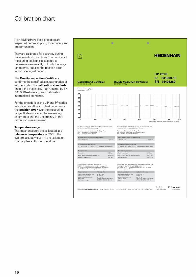
For the encoders of the LIP and PP series, in addition a calibration chart documents the position error over the measuring range. It also indicates the measuring parameters and the uncertainty of the calibration measurement.
Temperature rangeThe linear encoders are calibrated at a reference temperature of 20 °C. The system accuracy given in the calibration chart applies at this temperature.
Calibration chart
17
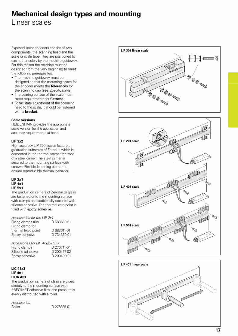
Mechanical design types and mountingLinear scales
Exposed linear encoders consist of two components: the scanning head and the scale or scale tape. They are positioned to each other solely by the machine guideway. For this reason the machine must be designed from the very beginning to meet the following prerequisites:• The machine guideway must be
designed so that the mounting space for the encoder meets the tolerances for the scanning gap (see Specifications).
• The bearing surface of the scale must meet requirements for flatness.
• To facilitate adjustment of the scanning head to the scale, it should be fastened with a bracket.
Scale versionsHEIDENHAIN provides the appropriate scale version for the application and accuracy requirements at hand.
LIP 3x2High-accuracy LIP 300 scales feature a graduation substrate of Zerodur, which is cemented in the thermal stress-free zone of a steel carrier. The steel carrier is secured to the mounting surface with screws. Flexible fastening elements ensure reproducible thermal behavior.
LIP 2x1LIP 4x1LIP 5x1The graduation carriers of Zerodur or glass are fastened onto the mounting surface with clamps and additionally secured with silicone adhesive. The thermal zero point is fixed with epoxy adhesive.
Accessories for the LIP 2x1Fixing clamps (6x) ID 683609-01Fixing clamp for thermal fixed point ID 683611-01Epoxy adhesive ID 734360-01
Accessories for LIP 4xx/LIP 5xxFixing clamps ID 270711-04Silicone adhesive ID 200417-02Epoxy adhesive ID 200409-01
LIC 41x3LIF 4x1LIDA 4x3The graduation carriers of glass are glued directly to the mounting surface with PRECIMET adhesive film, and pressure is evenly distributed with a roller.
AccessoriesRoller ID 276885-01
LIP 302 linear scale
LIP 401 scale
LIP 501 scale
LIF 401 linear scale
LIP 201 scale
18
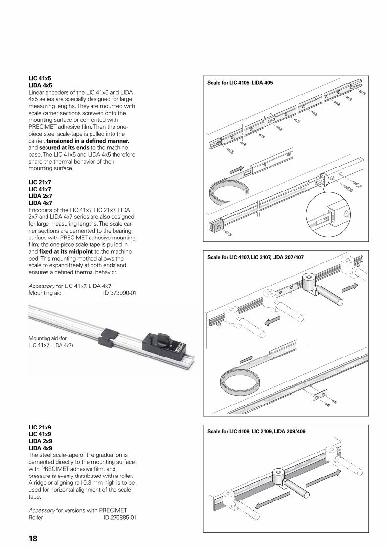
LIC 41x5LIDA 4x5Linear encoders of the LIC 41x5 and LIDA 4x5 series are specially designed for large measuring lengths. They are mounted with scale carrier sections screwed onto the mounting surface or cemented with PRECIMET adhesive fi lm. Then the one-piece steel scale-tape is pulled into the carrier, tensioned in a defi ned manner, and secured at its ends to the machine base. The LIC 41x5 and LIDA 4x5 therefore share the thermal behavior of their mounting surface.
LIC 21x7LIC 41x7LIDA 2x7LIDA 4x7Encoders of the LIC 41x7, LIC 21x7, LIDA 2x7 and LIDA 4x7 series are also designed for large measuring lengths. The scale car-rier sections are cemented to the bearing surface with PRECIMET adhesive mounting fi lm; the one-piece scale tape is pulled in and fi xed at its midpoint to the machine bed. This mounting method allows the scale to expand freely at both ends and ensures a defi ned thermal behavior.
Accessory for LIC 41x7, LIDA 4x7Mounting aid ID 373990-01
Scale for LIC 4109, LIC 2109, LIDA 209/409
Scale for LIC 4105, LIDA 405
Scale for LIC 4107, LIC 2107, LIDA 207/407
Mounting aid (for LIC 41x7, LIDA 4x7)
LIC 21x9 LIC 41x9LIDA 2x9LIDA 4x9The steel scale-tape of the graduation is cemented directly to the mounting surface with PRECIMET adhesive fi lm, and pressure is evenly distributed with a roller. A ridge or aligning rail 0.3 mm high is to be used for horizontal alignment of the scale tape.
Accessory for versions with PRECIMETRoller ID 276885-01
LIP 200
LIC/LIDA
LIP/LIF
19
Mechanical design types and mountingScanning heads
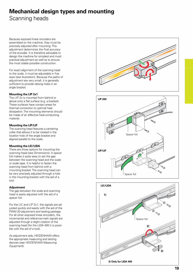
Because exposed linear encoders are assembled on the machine, they must be precisely adjusted after mounting. This adjustment determines the final accuracy of the encoder. It is therefore advisable to design the machine for simplest and most practical adjustment as well as to ensure the most stable possible construction.
For exact alignment of the scanning head to the scale, it must be adjustable in five axes (see illustration). Because the paths of adjustment are very small, it is generally sufficient to provide oblong holes in an angle bracket.
Mounting the LIP 2x1The LIP 2x is mounted from behind or above onto a flat surface (e.g. a bracket). These surfaces have contact areas for thermal connection to optimal heat dissipation. The mounting elements should be made of an effective heat-conducting material.
Mounting the LIP/LIFThe scanning head features a centering collar that allows it to be rotated in the location hole of the angle bracket and aligned parallel to the scale.
Mounting the LIC/LIDAThere are three options for mounting the scanning head (see Dimensions). A spacer foil makes it quite easy to set the gap between the scanning head and the scale or scale tape. It is helpful to fasten the scanning head from behind with a mounting bracket. The scanning head can be very precisely adjusted through a hole in the mounting bracket with the aid of a tool.
AdjustmentThe gap between the scale and scanning head is easily adjusted with the aid of a spacer foil.
For the LIC and LIP 2x1, the signals are ad-justed quickly and easily with the aid of the PWM 20 adjustment and testing package. For all other exposed linear encoders, the incremental and reference-mark signals are adjusted through a slight rotation of the scanning head (for the LIDA 400 it is possi-ble with the aid of a tool).
As adjustment aids, HEIDENHAIN offers the appropriate measuring and testing devices (see HEIDENHAIN Measuring Equipment).
Spacer foil
Spacer foil
Spacer foil
3) Only for LIDA 400
20
Scanning heads – LIDA 200 function display
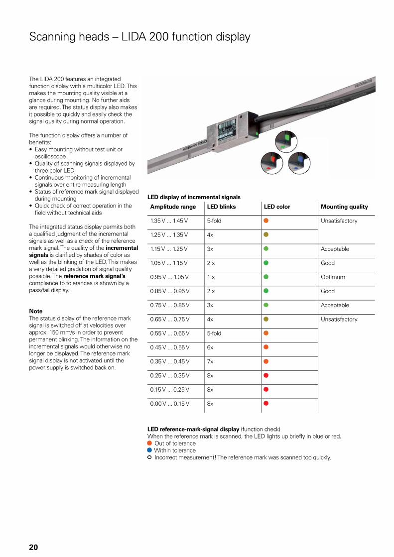
The LIDA 200 features an integrated function display with a multicolor LED. This makes the mounting quality visible at a glance during mounting. No further aids are required. The status display also makes it possible to quickly and easily check the signal quality during normal operation.
The function display offers a number of benefi ts:• Easy mounting without test unit or
oscilloscope• Quality of scanning signals displayed by
three-color LED• Continuous monitoring of incremental
signals over entire measuring length • Status of reference mark signal displayed
during mounting• Quick check of correct operation in the
fi eld without technical aids
The integrated status display permits both a qualifi ed judgment of the incremental signals as well as a check of the reference mark signal. The quality of the incremental signals is clarifi ed by shades of color as well as the blinking of the LED. This makes a very detailed gradation of signal quality possible. The reference mark signal’s compliance to tolerances is shown by a pass/fail display.
NoteThe status display of the reference mark signal is switched off at velocities over approx. 150 mm/s in order to prevent permanent blinking. The information on the incremental signals would otherwise no longer be displayed. The reference mark signal display is not activated until the power supply is switched back on.
LED display of incremental signals
Amplitude range LED blinks LED color Mounting quality
1.35 V ... 1.45 V 5-fold Unsatisfactory
1.25 V ... 1.35 V 4x
1.15 V ... 1.25 V 3x Acceptable
1.05 V ... 1.15 V 2 x Good
0.95 V ... 1.05 V 1 x Optimum
0.85 V ... 0.95 V 2 x Good
0.75 V ... 0.85 V 3x Acceptable
0.65 V ... 0.75 V 4x Unsatisfactory
0.55 V ... 0.65 V 5-fold
0.45 V ... 0.55 V 6x
0.35 V ... 0.45 V 7x
0.25 V ... 0.35 V 8x
0.15 V ... 0.25 V 8x
0.00 V ... 0.15 V 8x
LED reference-mark-signal display (function check)When the reference mark is scanned, the LED lights up briefl y in blue or red. Out of tolerance Within tolerance
Incorrect measurement! The reference mark was scanned too quickly.
21
AssemblyWork steps to be performed and dimensions to be maintained during mounting are specified solely in the mounting instructions supplied with the unit. All data in this catalog regarding mounting are therefore provisional and not binding; they do not become terms of a contract.
General mechanical information
Temperature rangeThe operating temperature range indicates the limits of ambient temperature within which the values given in the specifications for linear encoders are maintained.
The storage temperature range of –20 °C to +70 °C applies when the unit remains in its packaging.
Thermal characteristicsThe thermal behavior of the linear encoder is an essential criterion for the working accuracy of the machine. As a general rule, the thermal behavior of the linear encoder should match that of the workpiece or measured object. During temperature changes, the linear encoder should expand or contract in a defined, reproducible manner.
The graduation carriers of HEIDENHAIN linear encoders (see Specifications) have differing coefficients of thermal expansion. This makes it possible to select the linear encoder with thermal behavior best suited to the application.
Expendable partsEncoders from HEIDENHAIN are designed for a long service life. Preventive mainte-nance is not required. However, they contain components that are subject to wear, depending on the application and manipulation. These include in particular cables with frequent flexing.
Other such components are the bearings of encoders with integral bearing, shaft sealing rings on rotary and angle encoders, and sealing lips on sealed linear encoders.
Protection (EN 60 529)The scanning heads of the exposed linear encoders are protected against the ingress of liquid.
Scanning head Protection
LIC IP 67
LIDA IP 40
LIF IP 50
LIP 200 IP 30
LIP 300LIP 400LIP 500
IP 50
PP IP 50
The scales have no special protection. Protective measures must be taken if the possibility of contamination exists.
AccelerationLinear encoders are subjected to various types of acceleration during operation and mounting.• The indicated maximum values for
vibration apply for frequencies of 55 to 2 000 Hz (EN 60068-2-6). Any acceleration exceeding permissible values, for example due to resonance depending on the application and mounting, might damage the encoder. Comprehensive tests of the entire system are required.
• The maximum permissible acceleration values (semi-sinusoidal shock) for shock and impact are valid for 11 ms, or 6 ms for the LIC (EN 60 068-2-27). Under no circumstances should a hammer or similar implement be used to adjust or position the encoder.
System testsEncoders from HEIDENHAIN are usually integrated as components in larger systems. Such applications require comprehensive tests of the entire system regardless of the specifications of the encoder.
The specifications shown in this brochure apply to the specific encoder, not to the complete system. Any operation of the encoder outside of the specified range or for any other than the intended applications is at the user’s own risk.
In safety-related systems, the higher-level system must verify the position value of the encoder after switch-on.
DIADUR, SUPRADUR, METALLUR and OPTODUR are registered trademarks of DR. JOHANNES HEIDENHAIN GmbH, Traunreut.Zerodur® is a registered trademark of Schott-Glaswerke, Mainz, Germany.
22
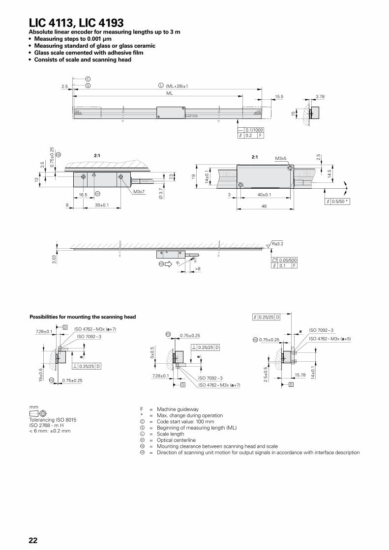
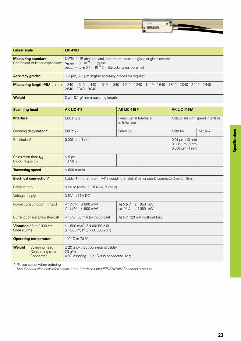
LIC 4113, LIC 4193Absolute linear encoder for measuring lengths up to 3 m• Measuring steps to 0.001 µm• Measuring standard of glass or glass ceramic• Glass scale cemented with adhesive film• Consists of scale and scanning head
F = Machine guideway* = Max. change during operationc = Code start value: 100 mms = Beginning of measuring length (ML)l = Scale length = Optical centerlineÁ = Mounting clearance between scanning head and scale = Direction of scanning unit motion for output signals in accordance with interface description
Possibilities for mounting the scanning head
23
Sp
ecifi
cati
on
s
Linear scale LIC 4103
Measuring standardCoeffi cient of linear expansion*
METALLUR absolute and incremental track on glass or glass ceramicÞtherm � 8 · 10–6 K–1 (glass) Þtherm = (0 ± 0.1) · 10–6 K–1 (Zerodur glass ceramic)
Accuracy grade* ± 3 µm, ± 5 µm (higher accuracy grades on request)
Measuring length ML* in mm 240 340 440 640 840 1 040 1 240 1 440 1 640 1 840 2 040 2 240 2 4402 640 2 840 3 040
Weight 3 g + 0.1 g/mm measuring length
Scanning head AK LIC 411 AK LIC 419 F AK LIC 419 M
Interface EnDat 2.2 Fanuc Serial InterfaceÞi Interface
Mitsubishi high speed interface
Ordering designation* EnDat22 Fanuc05 Mit03-4 Mit02-2
Resolution* 0.001 µm (1 nm) 0.01 µm (10 nm)0.005 µm (5 nm)0.001 µm (1 nm)
Calculation time tcalClock frequency
5 µs16 MHz
–
Traversing speed1) 600 m/min
Electrical connection* Cable, 1 m or 3 m with M12 coupling (male), 8-pin or sub-D connector (male), 15-pin
Cable length 50 m (with HEIDENHAIN cable)
Voltage supply 3.6 V to 14 V DC
Power consumption1) (max.) At 3.6 V: 800 mWAt 14 V: 900 mW
At 3.6 V: 950 mWAt 14 V: 1 050 mW
Current consumption (typical) At 5 V: 100 mA (without load) At 5 V: 120 mA (without load)
Vibration 55 to 2 000 HzShock 6 ms
500 m/s2 (EN 60 068-2-6) 1 000 m/s2 (EN 60 068-2-27)
Operating temperature –10 °C to 70 °C
Weight Scanning head Connecting cable Connector
20 g (without connecting cable)20 g/mM12 coupling: 15 g; D-sub connector: 32 g
* Please select when ordering1) See General electrical information in the Interfaces for HEIDENHAIN Encoders brochure
24
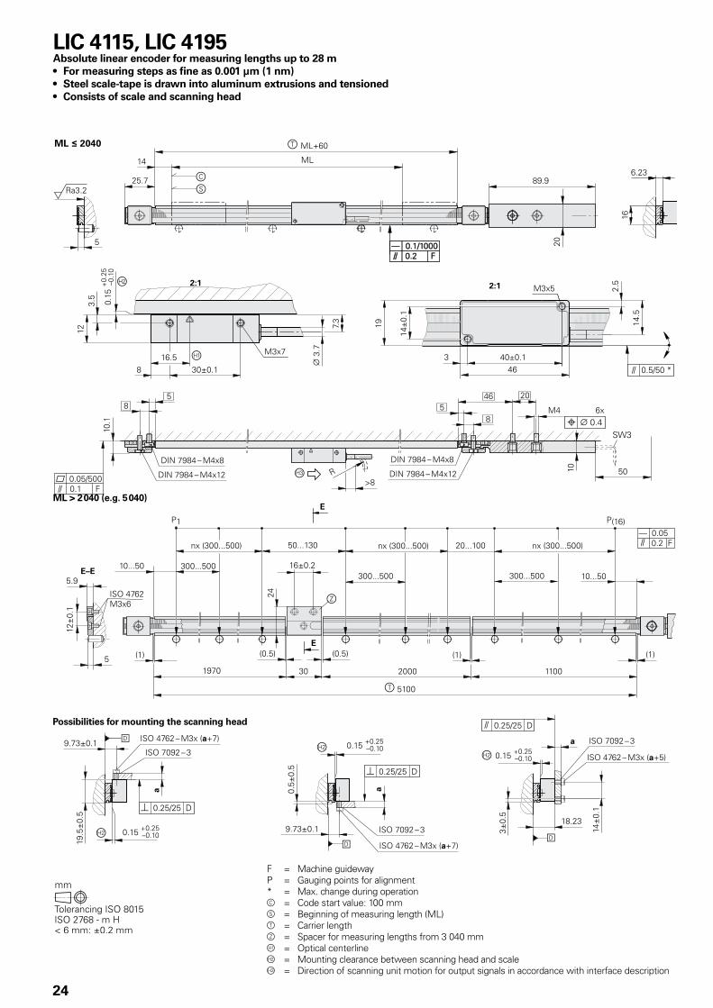
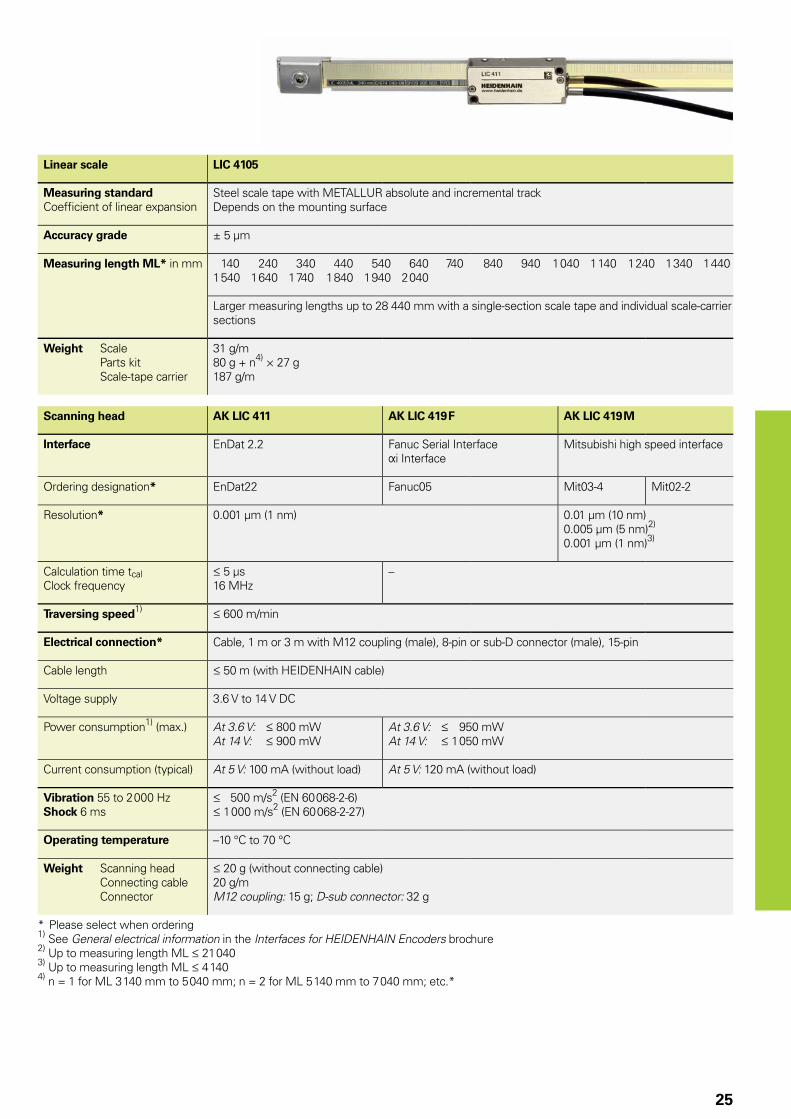
LIC 4115, LIC 4195Absolute linear encoder for measuring lengths up to 28 m• For measuring steps as fine as 0.001 µm (1 nm) • Steel scale-tape is drawn into aluminum extrusions and tensioned• Consists of scale and scanning head
F = Machine guidewayP = Gauging points for alignment* = Max. change during operationc = Code start value: 100 mms = Beginning of measuring length (ML)t = Carrier lengthz = Spacer for measuring lengths from 3 040 mm = Optical centerlineÁ = Mounting clearance between scanning head and scale = Direction of scanning unit motion for output signals in accordance with interface description
Possibilities for mounting the scanning head
ML > 2 040 (e.g. 5 040)
25
Linear scale LIC 4105
Measuring standardCoeffi cient of linear expansion
Steel scale tape with METALLUR absolute and incremental trackDepends on the mounting surface
Accuracy grade ± 5 µm
Measuring length ML* in mm 140 240 340 440 540 640 740 840 940 1 040 1 140 1 240 1 340 1 4401 540 1 640 1 740 1 840 1 940 2 040
Larger measuring lengths up to 28 440 mm with a single-section scale tape and individual scale-carrier sections
Weight Scale Parts kit Scale-tape carrier
31 g/m80 g + n4) × 27 g187 g/m
Scanning head AK LIC 411 AK LIC 419 F AK LIC 419 M
Interface EnDat 2.2 Fanuc Serial Interface Þi Interface
Mitsubishi high speed interface
Ordering designation* EnDat22 Fanuc05 Mit03-4 Mit02-2
Resolution* 0.001 µm (1 nm) 0.01 µm (10 nm)0.005 µm (5 nm)2)
0.001 µm (1 nm)3)
Calculation time tcalClock frequency
5 µs16 MHz
–
Traversing speed1) 600 m/min
Electrical connection* Cable, 1 m or 3 m with M12 coupling (male), 8-pin or sub-D connector (male), 15-pin
Cable length 50 m (with HEIDENHAIN cable)
Voltage supply 3.6 V to 14 V DC
Power consumption1) (max.) At 3.6 V: 800 mWAt 14 V: 900 mW
At 3.6 V: 950 mWAt 14 V: 1 050 mW
Current consumption (typical) At 5 V: 100 mA (without load) At 5 V: 120 mA (without load)
Vibration 55 to 2 000 HzShock 6 ms
500 m/s2 (EN 60 068-2-6) 1 000 m/s2 (EN 60 068-2-27)
Operating temperature –10 °C to 70 °C
Weight Scanning head Connecting cable Connector
20 g (without connecting cable)20 g/mM12 coupling: 15 g; D-sub connector: 32 g
* Please select when ordering1) See General electrical information in the Interfaces for HEIDENHAIN Encoders brochure2) Up to measuring length ML 21 0403) Up to measuring length ML 4 1404) n = 1 for ML 3 140 mm to 5 040 mm; n = 2 for ML 5 140 mm to 7 040 mm; etc.*
26
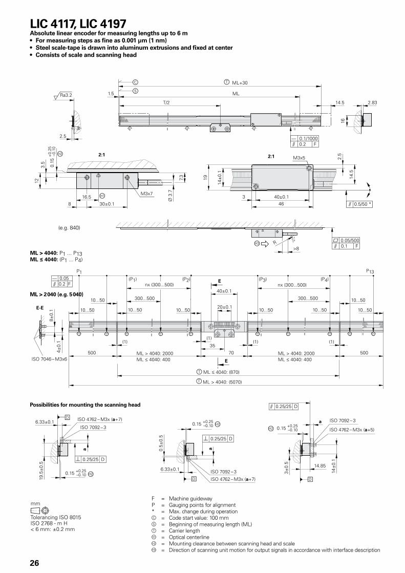
LIC 4117, LIC 4197Absolute linear encoder for measuring lengths up to 6 m• For measuring steps as fine as 0.001 µm (1 nm) • Steel scale-tape is drawn into aluminum extrusions and fixed at center• Consists of scale and scanning head
F = Machine guidewayP = Gauging points for alignment* = Max. change during operationc = Code start value: 100 mms = Beginning of measuring length (ML)t = Carrier length = Optical centerlineÁ = Mounting clearance between scanning head and scale = Direction of scanning unit motion for output signals in accordance with interface description
Possibilities for mounting the scanning head
ML > 2 040 (e.g. 5 040)
(e.g. 840)
27
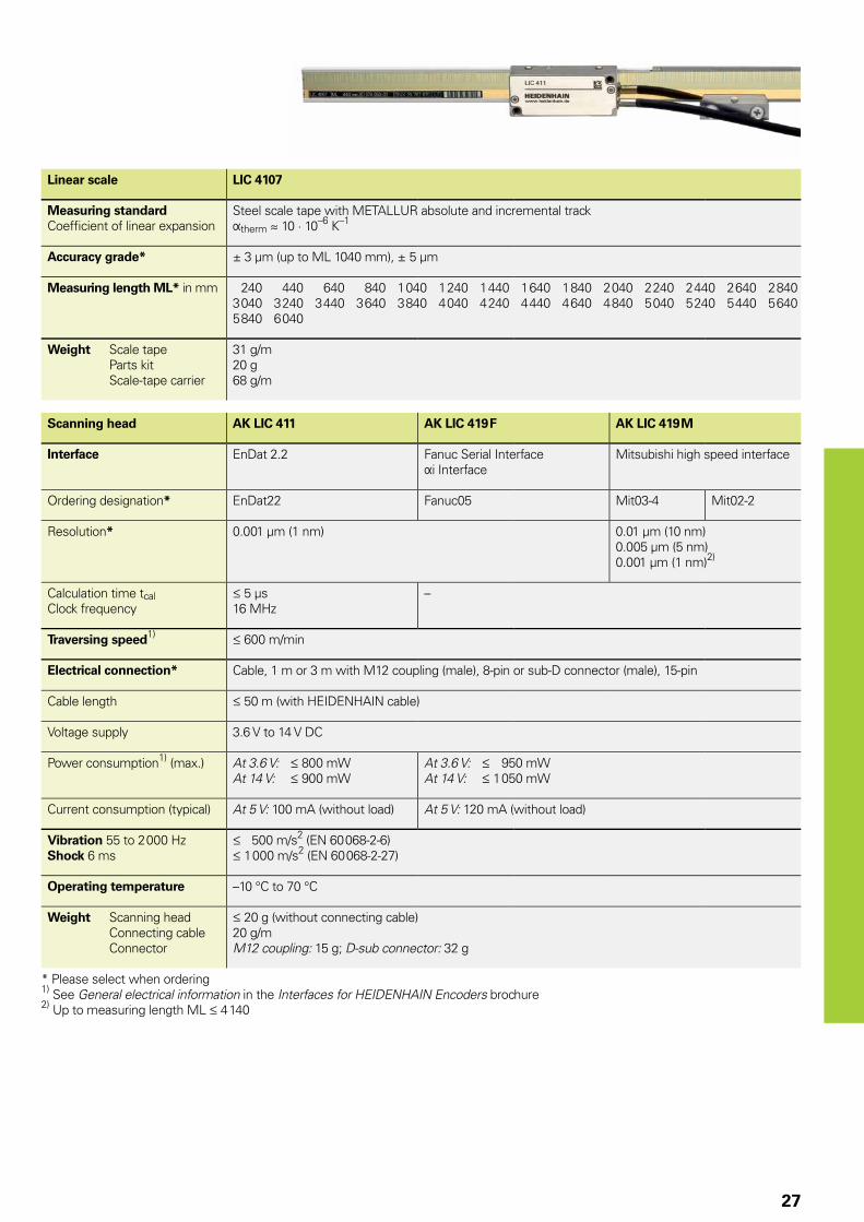
Linear scale LIC 4107
Measuring standardCoeffi cient of linear expansion
Steel scale tape with METALLUR absolute and incremental trackÞtherm � 10 · 10–6 K–1
Accuracy grade* ± 3 µm (up to ML 1040 mm), ± 5 µm
Measuring length ML* in mm 240 440 640 840 1 040 1 240 1 440 1 640 1 840 2 040 2 240 2 440 2 640 2 8403 040 3 240 3 440 3 640 3 840 4 040 4 240 4 440 4 640 4 840 5 040 5 240 5 440 5 6405 840 6 040
Weight Scale tape Parts kit Scale-tape carrier
31 g/m20 g68 g/m
Scanning head AK LIC 411 AK LIC 419 F AK LIC 419 M
Interface EnDat 2.2 Fanuc Serial Interface Þi Interface
Mitsubishi high speed interface
Ordering designation* EnDat22 Fanuc05 Mit03-4 Mit02-2
Resolution* 0.001 µm (1 nm) 0.01 µm (10 nm)0.005 µm (5 nm)0.001 µm (1 nm)2)
Calculation time tcalClock frequency
5 µs16 MHz
–
Traversing speed1) 600 m/min
Electrical connection* Cable, 1 m or 3 m with M12 coupling (male), 8-pin or sub-D connector (male), 15-pin
Cable length 50 m (with HEIDENHAIN cable)
Voltage supply 3.6 V to 14 V DC
Power consumption1) (max.) At 3.6 V: 800 mWAt 14 V: 900 mW
At 3.6 V: 950 mWAt 14 V: 1 050 mW
Current consumption (typical) At 5 V: 100 mA (without load) At 5 V: 120 mA (without load)
Vibration 55 to 2 000 HzShock 6 ms
500 m/s2 (EN 60 068-2-6) 1 000 m/s2 (EN 60 068-2-27)
Operating temperature –10 °C to 70 °C
Weight Scanning head Connecting cable Connector
20 g (without connecting cable)20 g/mM12 coupling: 15 g; D-sub connector: 32 g
* Please select when ordering1) See General electrical information in the Interfaces for HEIDENHAIN Encoders brochure2) Up to measuring length ML 4 140
28
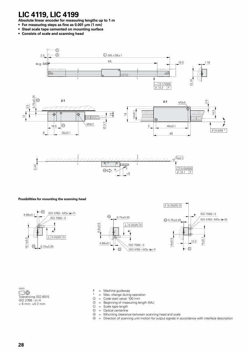
F = Machine guideway* = Max. change during operationc = Code start value: 100 mms = Beginning of measuring length (ML)l = Scale tape length = Optical centerlineÁ = Mounting clearance between scanning head and scale = Direction of scanning unit motion for output signals in accordance with interface description
LIC 4119, LIC 4199Absolute linear encoder for measuring lengths up to 1 m• For measuring steps as fine as 0.001 µm (1 nm) • Steel scale tape cemented on mounting surface• Consists of scale and scanning head
Possibilities for mounting the scanning head
(e.g. 840)
29
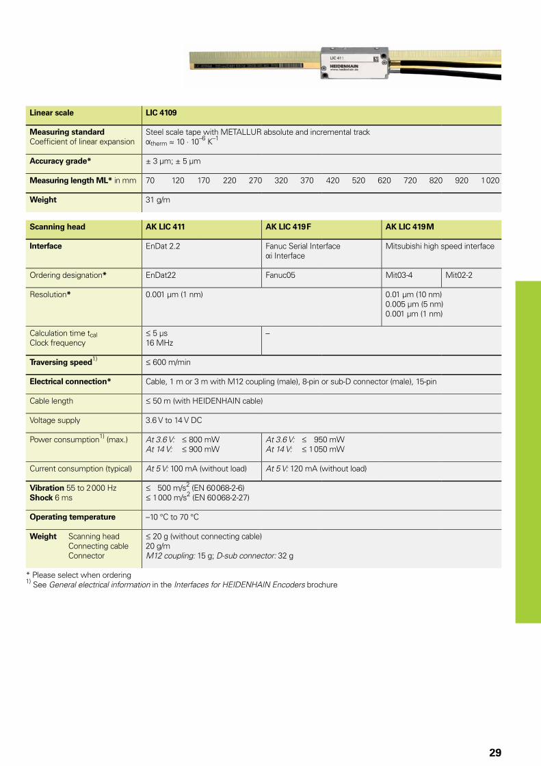
Linear scale LIC 4109
Measuring standardCoeffi cient of linear expansion
Steel scale tape with METALLUR absolute and incremental trackÞtherm � 10 · 10–6 K–1
Accuracy grade* ± 3 µm; ± 5 µm
Measuring length ML* in mm 70 120 170 220 270 320 370 420 520 620 720 820 920 1 020
Weight 31 g/m
Scanning head AK LIC 411 AK LIC 419 F AK LIC 419 M
Interface EnDat 2.2 Fanuc Serial Interface Þi Interface
Mitsubishi high speed interface
Ordering designation* EnDat22 Fanuc05 Mit03-4 Mit02-2
Resolution* 0.001 µm (1 nm) 0.01 µm (10 nm)0.005 µm (5 nm)0.001 µm (1 nm)
Calculation time tcalClock frequency
5 µs16 MHz
–
Traversing speed1) 600 m/min
Electrical connection* Cable, 1 m or 3 m with M12 coupling (male), 8-pin or sub-D connector (male), 15-pin
Cable length 50 m (with HEIDENHAIN cable)
Voltage supply 3.6 V to 14 V DC
Power consumption1) (max.) At 3.6 V: 800 mWAt 14 V: 900 mW
At 3.6 V: 950 mWAt 14 V: 1 050 mW
Current consumption (typical) At 5 V: 100 mA (without load) At 5 V: 120 mA (without load)
Vibration 55 to 2 000 HzShock 6 ms
500 m/s2 (EN 60 068-2-6) 1 000 m/s2 (EN 60 068-2-27)
Operating temperature –10 °C to 70 °C
Weight Scanning head Connecting cable Connector
20 g (without connecting cable)20 g/mM12 coupling: 15 g; D-sub connector: 32 g
* Please select when ordering1) See General electrical information in the Interfaces for HEIDENHAIN Encoders brochure
30
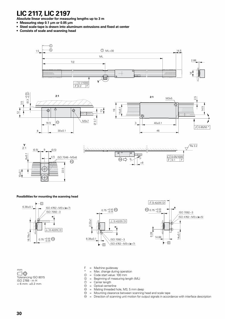
LIC 2117, LIC 2197Absolute linear encoder for measuring lengths up to 3 m• Measuring step 0.1 µm or 0.05 µm• Steel scale-tape is drawn into aluminum extrusions and fixed at center• Consists of scale and scanning head
Possibilities for mounting the scanning head
F = Machine guideway* = Max. change during operationc = Code start value: 100 mms = Beginning of measuring length (ML)t = Carrier length = Optical centerlineÁ = Mating threaded hole, M3, 5 mm deep = Mounting clearance between scanning head and scale tapeà = Direction of scanning unit motion for output signals in accordance with interface description
31
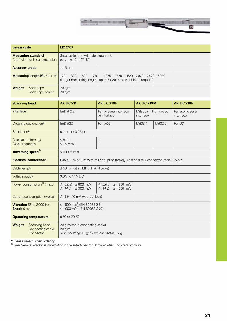
Linear scale LIC 2107
Measuring standardCoefficient of linear expansion
Steel scale tape with absolute trackÞtherm � 10 · 10–6 K–1
Accuracy grade ± 15 µm
Measuring length ML* in mm 120 320 520 770 1 020 1 220 1 520 2 020 2 420 3 020(Larger measuring lengths up to 6 020 mm available on request)
Weight Scale tape Scale-tape carrier
20 g/m70 g/m
Scanning head AK LIC 211 AK LIC 219 F AK LIC 219 M AK LIC 219 P
Interface EnDat 2.2 Fanuc serial interface Þi interface
Mitsubishi high speed interface
Panasonic serial interface
Ordering designation* EnDat22 Fanuc05 Mit03-4 Mit02-2 Pana01
Resolution* 0.1 µm or 0.05 µm
Calculation time tcalClock frequency
5 µs 16 MHz
––
Traversing speed1) 600 m/min
Electrical connection* Cable, 1 m or 3 m with M12 coupling (male), 8-pin or sub-D connector (male), 15-pin
Cable length 50 m (with HEIDENHAIN cable)
Voltage supply 3.6 V to 14 V DC
Power consumption1) (max.) At 3.6 V: 800 mWAt 14 V: 900 mW
At 3.6 V: 950 mWAt 14 V: 1 050 mW
Current consumption (typical) At 5 V: 110 mA (without load)
Vibration 55 to 2 000 HzShock 6 ms
500 m/s2 (EN 60 068-2-6) 1 000 m/s2 (EN 60 068-2-27)
Operating temperature 0 °C to 70 °C
Weight Scanning head Connecting cable Connector
20 g (without connecting cable)20 g/mM12 coupling: 15 g; D-sub connector: 32 g
* Please select when ordering1) See General electrical information in the Interfaces for HEIDENHAIN Encoders brochure
32
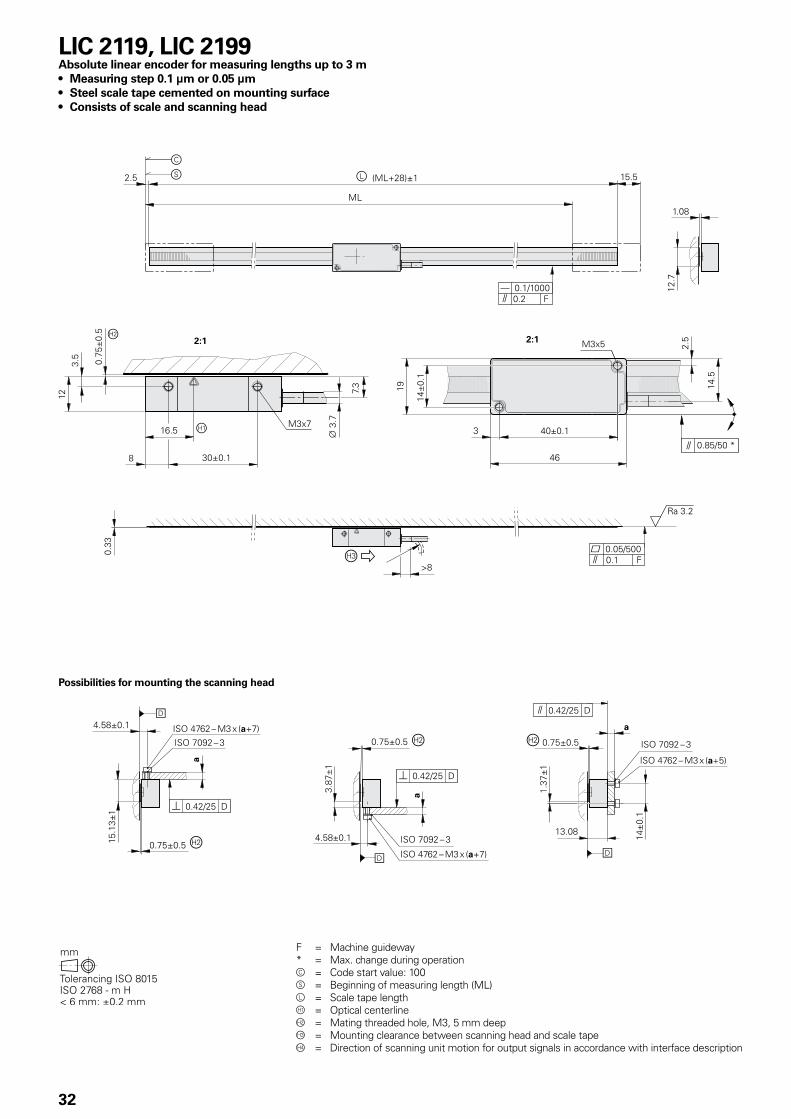
LIC 2119, LIC 2199Absolute linear encoder for measuring lengths up to 3 m• Measuring step 0.1 µm or 0.05 µm• Steel scale tape cemented on mounting surface• Consists of scale and scanning head
Possibilities for mounting the scanning head
F = Machine guideway* = Max. change during operationc = Code start value: 100s = Beginning of measuring length (ML)l = Scale tape length = Optical centerlineÁ = Mating threaded hole, M3, 5 mm deep = Mounting clearance between scanning head and scale tapeà = Direction of scanning unit motion for output signals in accordance with interface description
33
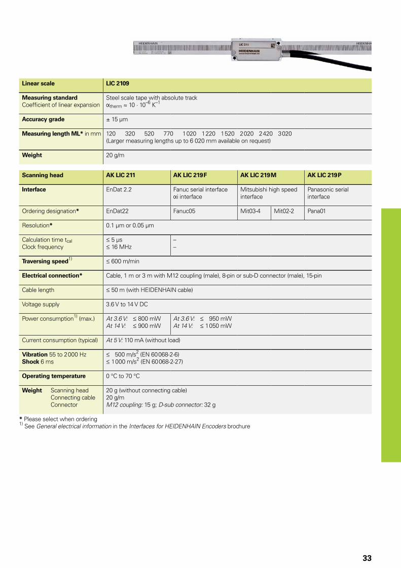
Linear scale LIC 2109
Measuring standardCoefficient of linear expansion
Steel scale tape with absolute trackÞtherm � 10 · 10–6 K–1
Accuracy grade ± 15 µm
Measuring length ML* in mm 120 320 520 770 1 020 1 220 1 520 2 020 2 420 3 020(Larger measuring lengths up to 6 020 mm available on request)
Weight 20 g/m
Scanning head AK LIC 211 AK LIC 219 F AK LIC 219 M AK LIC 219 P
Interface EnDat 2.2 Fanuc serial interface Þi interface
Mitsubishi high speed interface
Panasonic serial interface
Ordering designation* EnDat22 Fanuc05 Mit03-4 Mit02-2 Pana01
Resolution* 0.1 µm or 0.05 µm
Calculation time tcalClock frequency
5 µs 16 MHz
––
Traversing speed1) 600 m/min
Electrical connection* Cable, 1 m or 3 m with M12 coupling (male), 8-pin or sub-D connector (male), 15-pin
Cable length 50 m (with HEIDENHAIN cable)
Voltage supply 3.6 V to 14 V DC
Power consumption1) (max.) At 3.6 V: 800 mWAt 14 V: 900 mW
At 3.6 V: 950 mWAt 14 V: 1 050 mW
Current consumption (typical) At 5 V: 110 mA (without load)
Vibration 55 to 2 000 HzShock 6 ms
500 m/s2 (EN 60 068-2-6) 1 000 m/s2 (EN 60 068-2-27)
Operating temperature 0 °C to 70 °C
Weight Scanning head Connecting cable Connector
20 g (without connecting cable)20 g/mM12 coupling: 15 g; D-sub connector: 32 g
* Please select when ordering1) See General electrical information in the Interfaces for HEIDENHAIN Encoders brochure
INVISIBLE LASER RADIATION
IEC60825-1:2001Pmax = 4 mW
λ= 850 nm
CLASS 3B LASER PRODUCT
34
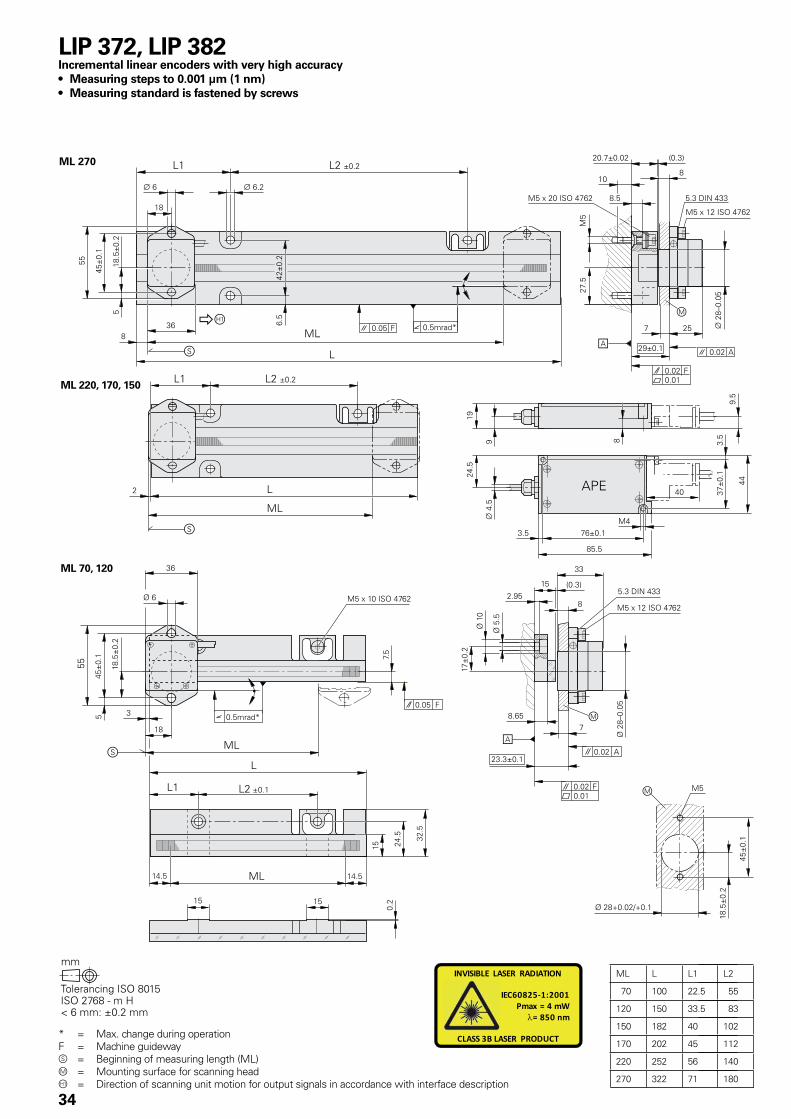
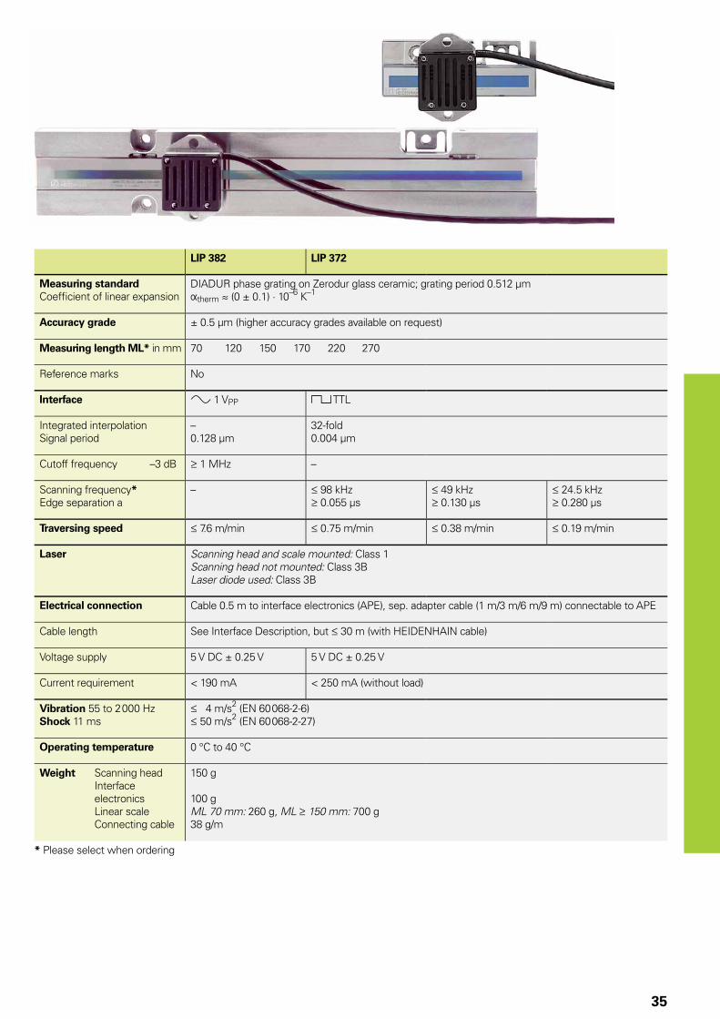
LIP 372, LIP 382Incremental linear encoders with very high accuracy • Measuring steps to 0.001 µm (1 nm)• Measuring standard is fastened by screws
* = Max. change during operationF = Machine guideways = Beginning of measuring length (ML)m = Mounting surface for scanning head = Direction of scanning unit motion for output signals in accordance with interface description
35
LIP 382 LIP 372
Measuring standardCoeffi cient of linear expansion
DIADUR phase grating on Zerodur glass ceramic; grating period 0.512 µm Þtherm � (0 ± 0.1) · 10–6 K–1
Accuracy grade ± 0.5 µm (higher accuracy grades available on request)
Measuring length ML* in mm 70 120 150 170 220 270
Reference marks No
Interface » 1 VPP « TTL
Integrated interpolationSignal period
–0.128 µm
32-fold0.004 µm
Cutoff frequency –3 dB 1 MHz –
Scanning frequency*Edge separation a
– 98 kHz 0.055 µs
49 kHz 0.130 µs
24.5 kHz 0.280 µs
Traversing speed 7.6 m/min 0.75 m/min 0.38 m/min 0.19 m/min
Laser Scanning head and scale mounted: Class 1Scanning head not mounted: Class 3BLaser diode used: Class 3B
Electrical connection Cable 0.5 m to interface electronics (APE), sep. adapter cable (1 m/3 m/6 m/9 m) connectable to APE
Cable length See Interface Description, but 30 m (with HEIDENHAIN cable)
Voltage supply 5 V DC ± 0.25 V 5 V DC ± 0.25 V
Current requirement < 190 mA < 250 mA (without load)
Vibration 55 to 2 000 HzShock 11 ms
4 m/s2 (EN 60 068-2-6) 50 m/s2 (EN 60 068-2-27)
Operating temperature 0 °C to 40 °C
Weight Scanning head Interface
electronics Linear scale Connecting cable
150 g
100 gML 70 mm: 260 g, ML 150 mm: 700 g38 g/m
* Please select when ordering
INVISIBLE LASER RADIATION
IEC60825-1:2001Pmax = 4 mW
λ= 850 nm
CLASS 3B LASER PRODUCT
36
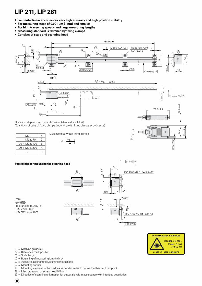
F = Machine guidewayr = Reference mark positionl = Scale lengths = Beginning of measuring length (ML)e = Adhesive according to Mounting Instructionsa = Mounting surface = Mounting element for hard adhesive bond in order to define the thermal fixed pointÁ = Max. protrusion of screw head 0.5 mm = Direction of scanning unit motion for output signals in accordance with interface description
LIP 211, LIP 281Incremental linear encoders for very high accuracy and high position stability• For measuring steps of 0.001 µm (1 nm) and smaller• For high traversing speeds and large measuring lengths• Measuring standard is fastened by fixing clamps• Consists of scale and scanning head
Distance r depends on the scale variant (standard: r = ML/2)Quantity n of pairs of fixing clamps (mounting with fixing clamps at both ends)
Distance d between fixing clamps:
Possibilities for mounting the scanning head
37
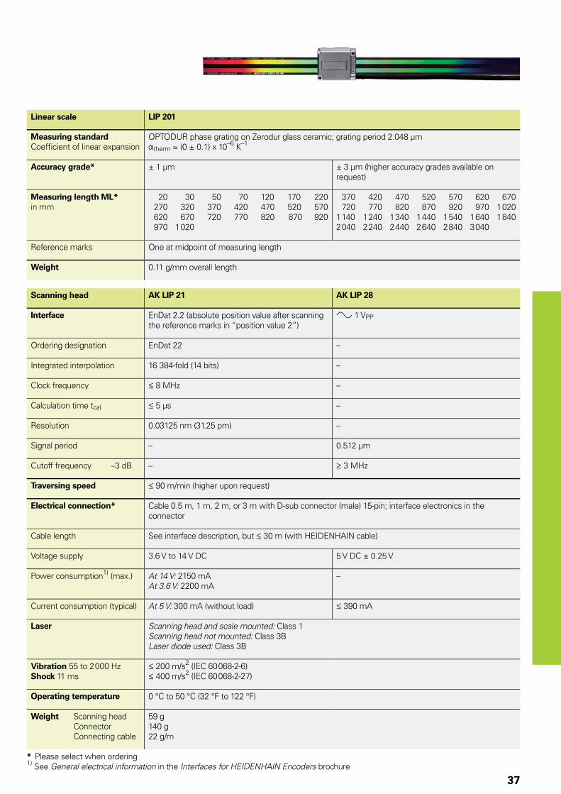
Linear scale LIP 201
Measuring standardCoeffi cient of linear expansion
OPTODUR phase grating on Zerodur glass ceramic; grating period 2.048 µmÞtherm � (0 ± 0.1) x 10–6 K–1
Accuracy grade* ± 1 µm ± 3 µm (higher accuracy grades available on request)
Measuring length ML*in mm
20 30 50 70 120 170 220 270 320 370 420 470 520 570 620 670 720 770 820 870 920 970 1 020
370 420 470 520 570 620 670 720 770 820 870 920 970 1 020 1 140 1 240 1 340 1 440 1 540 1 640 1 840 2 040 2 240 2 440 2 640 2 840 3 040
Reference marks One at midpoint of measuring length
Weight 0.11 g/mm overall length
Scanning head AK LIP 21 AK LIP 28
Interface EnDat 2.2 (absolute position value after scanning the reference marks in “position value 2”)
» 1 VPP
Ordering designation EnDat 22 –
Integrated interpolation 16 384-fold (14 bits) –
Clock frequency 8 MHz –
Calculation time tcal 5 µs –
Resolution 0.03125 nm (31.25 pm) –
Signal period – 0.512 µm
Cutoff frequency –3 dB – 3 MHz
Traversing speed 90 m/min (higher upon request)
Electrical connection* Cable 0.5 m, 1 m, 2 m, or 3 m with D-sub connector (male) 15-pin; interface electronics in the connector
Cable length See interface description, but 30 m (with HEIDENHAIN cable)
Voltage supply 3.6 V to 14 V DC 5 V DC ± 0.25 V
Power consumption1) (max.) At 14 V: 2150 mAAt 3.6 V: 2200 mA
–
Current consumption (typical) At 5 V: 300 mA (without load) 390 mA
Laser Scanning head and scale mounted: Class 1Scanning head not mounted: Class 3BLaser diode used: Class 3B
Vibration 55 to 2 000 HzShock 11 ms
200 m/s2 (IEC 60 068-2-6) 400 m/s2 (IEC 60 068-2-27)
Operating temperature 0 °C to 50 °C (32 °F to 122 °F)
Weight Scanning head Connector Connecting cable
59 g140 g22 g/m
* Please select when ordering1) See General electrical information in the Interfaces for HEIDENHAIN Encoders brochure
38
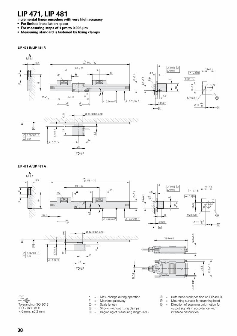
* = Max. change during operationF = Machine guidewayl = Scale lengthd = Shown without fixing clampss = Beginning of measuring length (ML)
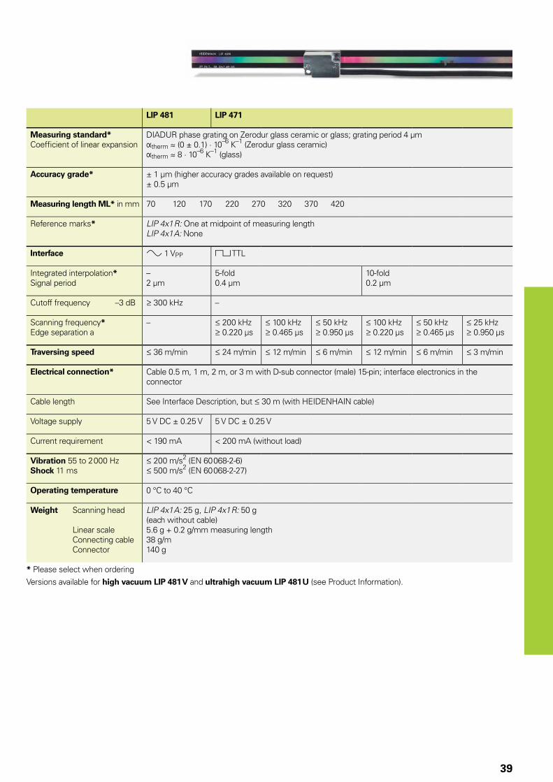
LIP 471, LIP 481Incremental linear encoders with very high accuracy• For limited installation space• For measuring steps of 1 µm to 0.005 µm• Measuring standard is fastened by fixing clamps
r = Reference-mark position on LIP 4x1 Rm = Mounting surface for scanning head = Direction of scanning unit motion for
output signals in accordance with interface description
39
LIP 481 LIP 471
Measuring standard*Coeffi cient of linear expansion
DIADUR phase grating on Zerodur glass ceramic or glass; grating period 4 µmÞtherm � (0 ± 0.1) · 10–6 K–1 (Zerodur glass ceramic) Þtherm � 8 · 10–6 K–1 (glass)
Accuracy grade* ± 1 µm (higher accuracy grades available on request)± 0.5 µm
Measuring length ML* in mm 70 120 170 220 270 320 370 420
Reference marks* LIP 4x1 R: One at midpoint of measuring lengthLIP 4x1 A: None
Interface » 1 VPP « TTL
Integrated interpolation*Signal period
–2 µm
5-fold0.4 µm
10-fold0.2 µm
Cutoff frequency –3 dB 300 kHz –
Scanning frequency*Edge separation a
– 200 kHz 0.220 µs
100 kHz 0.465 µs
50 kHz 0.950 µs
100 kHz 0.220 µs
50 kHz 0.465 µs
25 kHz 0.950 µs
Traversing speed 36 m/min 24 m/min 12 m/min 6 m/min 12 m/min 6 m/min 3 m/min
Electrical connection* Cable 0.5 m, 1 m, 2 m, or 3 m with D-sub connector (male) 15-pin; interface electronics in the connector
Cable length See Interface Description, but 30 m (with HEIDENHAIN cable)
Voltage supply 5 V DC ± 0.25 V 5 V DC ± 0.25 V
Current requirement < 190 mA < 200 mA (without load)
Vibration 55 to 2 000 HzShock 11 ms
200 m/s2 (EN 60 068-2-6) 500 m/s2 (EN 60 068-2-27)
Operating temperature 0 °C to 40 °C
Weight Scanning head
Linear scale Connecting cable Connector
LIP 4x1 A: 25 g, LIP 4x1 R: 50 g (each without cable)5.6 g + 0.2 g/mm measuring length38 g/m140 g
* Please select when orderingVersions available for high vacuum LIP 481 V and ultrahigh vacuum LIP 481 U (see Product Information).
40
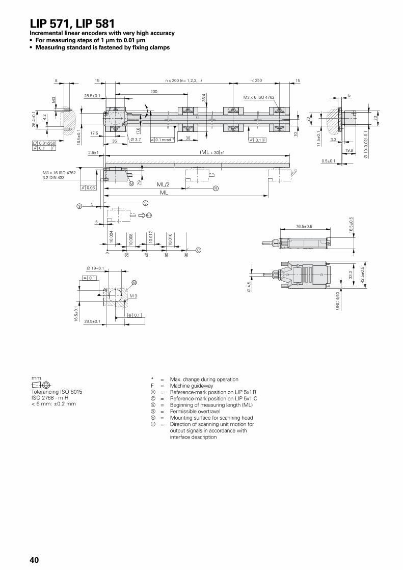
* = Max. change during operationF = Machine guidewayr = Reference-mark position on LIP 5x1 Rc = Reference-mark position on LIP 5x1 Cs = Beginning of measuring length (ML)Ø = Permissible overtravelm = Mounting surface for scanning head = Direction of scanning unit motion for
output signals in accordance with interface description
LIP 571, LIP 581Incremental linear encoders with very high accuracy• For measuring steps of 1 µm to 0.01 µm• Measuring standard is fastened by fixing clamps
41
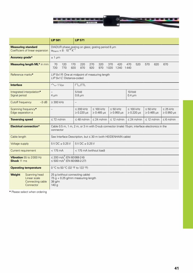
LIP 581 LIP 571
Measuring standardCoeffi cient of linear expansion
DIADUR phase grating on glass; grating period 8 µmÞtherm � 8 · 10–6 K–1
Accuracy grade* ± 1 µm
Measuring length ML* in mm 70 120 170 220 270 320 370 420 470 520 570 620 670 720 770 820 870 920 970 1 020 1 240 1 440
Reference marks* LIP 5x1 R: One at midpoint of measuring lengthLIP 5x1 C: Distance-coded
Interface » 1 VPP « TTL
Integrated interpolation*Signal period
–4 µm
5-fold0.8 µm
10-fold0.4 µm
Cutoff frequency –3 dB 300 kHz –
Scanning frequency*Edge separation a
– 200 kHz 0.220 µs
100 kHz 0.465 µs
50 kHz 0.950 µs
100 kHz 0.220 µs
50 kHz 0.465 µs
25 kHz 0.950 µs
Traversing speed 72 m/min 48 m/min 24 m/min 12 m/min 24 m/min 12 m/min 6 m/min
Electrical connection* Cable 0.5 m, 1 m, 2 m, or 3 m with D-sub connector (male) 15-pin; interface electronics in the connector
Cable length See Interface Description, but 30 m (with HEIDENHAIN cable)
Voltage supply 5 V DC ± 0.25 V 5 V DC ± 0.25 V
Current requirement < 175 mA < 175 mA (without load)
Vibration 55 to 2 000 HzShock 11 ms
200 m/s2 (EN 60 068-2-6) 500 m/s2 (EN 60 068-2-27)
Operating temperature 0 °C to 50 °C (32 °F to 122 °F)
Weight Scanning head Linear scale Connecting cable Connector
25 g (without connecting cable)7.5 g + 0.25 g/mm measuring length38 g/m140 g
* Please select when ordering
42
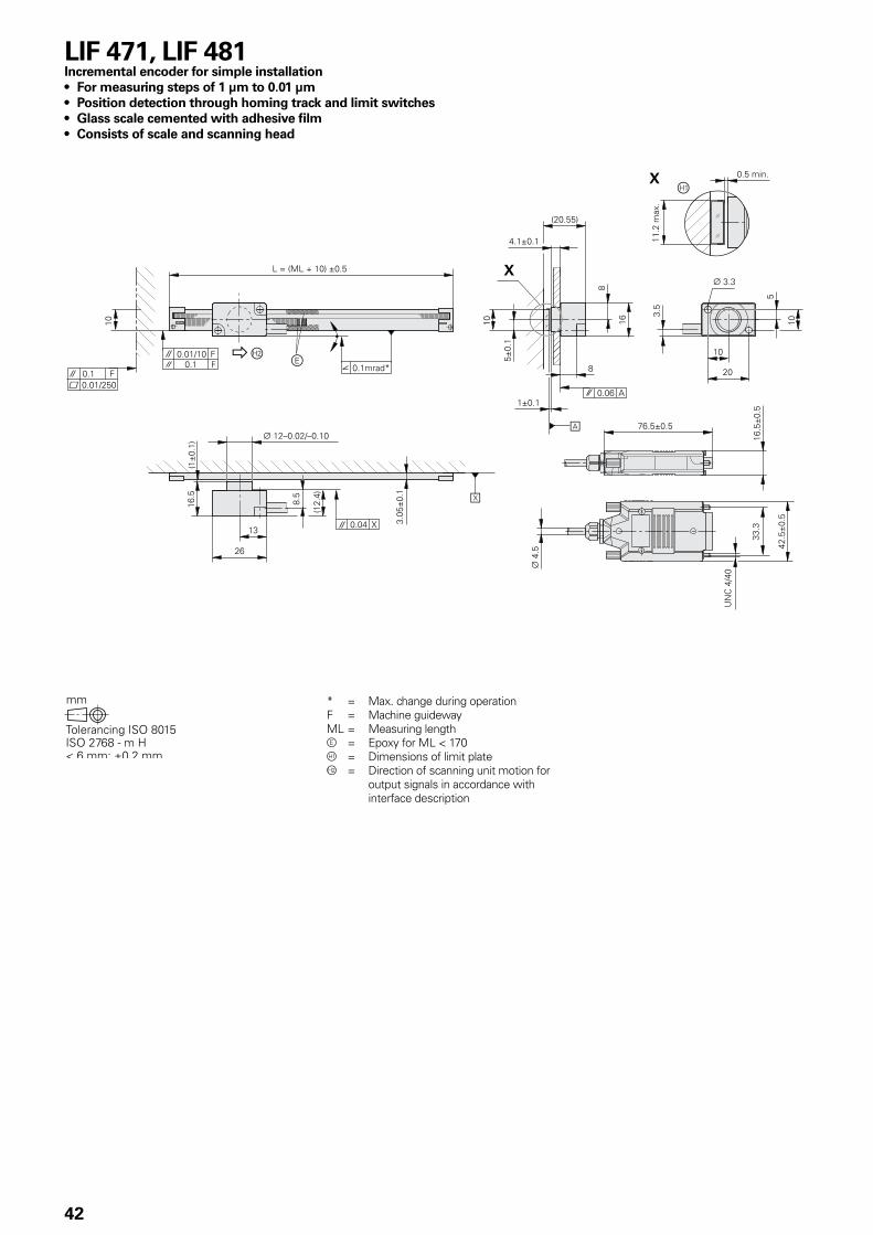
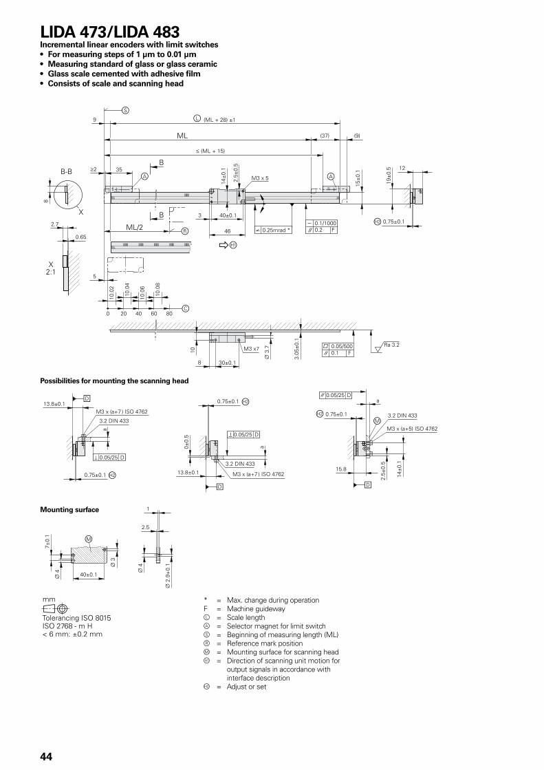
* = Max. change during operationF = Machine guidewayML = Measuring lengthe = Epoxy for ML < 170 = Dimensions of limit plateÁ = Direction of scanning unit motion for
output signals in accordance with interface description
LIF 471, LIF 481Incremental encoder for simple installation• For measuring steps of 1 µm to 0.01 µm• Position detection through homing track and limit switches• Glass scale cemented with adhesive film• Consists of scale and scanning head
43
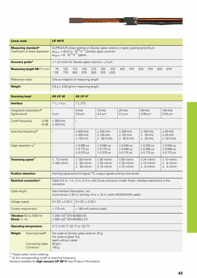
Linear scale LIF 401 R
Measuring standard*Coeffi cient of linear expansion
SUPRADUR phase grating on Zerodur glass ceramic or glass; grating period 8 µmÞtherm � (0±0,1) · 10–6 K–1 (Zerodur glass ceramic)Þtherm � 8 · 10–6 K–1 (glass)
Accuracy grade* ± 1 µm (only for Zerodur glass ceramic), ± 3 µm
Measuring length ML* in mm 70 120 170 220 270 320 370 420 470 520 570 620 670 720 770 820 870 920 970 1 020
Reference marks One at midpoint of measuring length
Weight 0.8 g + 0.08 g/mm measuring length
Scanning head AK LIF 48 AK LIF 47
Interface » 1 VPP « TTL
Integrated interpolation*Signal period
–4 µm
5-fold0.8 µm
10-fold0.4 µm
20-fold0.2 µm
50-fold0.08 µm
100-fold0.04 µm
Cutoff frequency –3 dB –6 dB
300 kHz 420 kHz
–
Scanning frequency* – 500 kHz 250 kHz 125 kHz
250 kHz 125 kHz 62.5 kHz
250 kHz 125 kHz 62.5 kHz
100 kHz 50 kHz 25 kHz
50 kHz 25 kHz 12.5 kHz
Edge separation a1) – 0.080 µs 0.175 µs 0.370 µs
0.080 µs 0.175 µs 0.370 µs
0.040 µs 0.080 µs 0.175 µs
0.040 µs 0.080 µs 0.175 µs
0.040 µs 0.080 µs 0.175 µs
Traversing speed1) 72 m/min 100 m/min
120 m/min 60 m/min 30 m/min
60 m/min 30 m/min 15 m/min
60 m/min 30 m/min 15 m/min
24 m/min 12 m/min 6 m/min
12 m/min 6 m/min 3 m/min
Position detection Homing signal and limit signal; TTL output signals (without line driver)
Electrical connection* Cable 0.5 m, 1 m, 2 m, or 3 m with D-sub connector (male) 15-pin; interface electronics in the connector
Cable length See Interface Description, but incremental: 30 m; homing, limit: 10 m; (with HEIDENHAIN cable)
Voltage supply 5 V DC ± 0.25 V 5 V DC ± 0.25 V
Current requirement < 175 mA < 180 mA (without load)
Vibration 55 to 2 000 HzShock 11 ms
200 m/s2 (EN 60 068-2-6) 500 m/s2 (EN 60 068-2-27)
Operating temperature 0 °C to 50 °C (32 °F to 122 °F)
Weight Scanning head*
Connecting cable Connector
For scale of Zerodur glass ceramic: 25 gFor scale of glass: 9 g(each without cable)38 g/m140 g
* Please select when ordering1) At the corresponding cutoff or scanning frequencyVersions available for high vacuum LIP 481 V (see Product Information).
44
LIDA 473/LIDA 483Incremental linear encoders with limit switches• For measuring steps of 1 µm to 0.01 µm• Measuring standard of glass or glass ceramic• Glass scale cemented with adhesive film• Consists of scale and scanning head
* = Max. change during operationF = Machine guidewayl = Scale lengtha = Selector magnet for limit switchs = Beginning of measuring length (ML)r = Reference mark positionm = Mounting surface for scanning head = Direction of scanning unit motion for
output signals in accordance with interface description
Á = Adjust or set
Possibilities for mounting the scanning head
Mounting surface
45
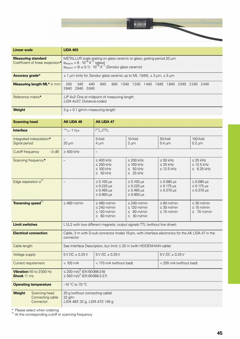
Linear scale LIDA 403
Measuring standardCoeffi cient of linear expansion*
METALLUR scale grating on glass ceramic or glass; grating period 20 µmÞtherm � 8 · 10–6 K–1 (glass)Þtherm = (0 ± 0.1) · 10–6 K–1 (Zerodur glass ceramic)
Accuracy grade* ± 1 µm (only for Zerodur glass ceramic up to ML 1 640), ± 3 µm, ± 5 µm
Measuring length ML* in mm 240 340 440 640 840 1 040 1 240 1 440 1 640 1 840 2 040 2 240 2 4402 640 2 840 3 040
Reference marks* LIP 4x3: One at midpoint of measuring lengthLIDA 4x3 C: Distance-coded
Weight 3 g + 0.1 g/mm measuring length
Scanning head AK LIDA 48 AK LIDA 47
Interface » 1 VPP « TTL
Integrated interpolation*Signal period
–20 µm
5-fold4 µm
10-fold2 µm
50-fold0.4 µm
100-fold0.2 µm
Cutoff frequency –3 dB 400 kHz –
Scanning frequency* – 400 kHz 200 kHz 100 kHz 50 kHz
200 kHz 100 kHz 50 kHz 25 kHz
50 kHz 25 kHz 12.5 kHz
25 kHz 12.5 kHz 6.25 kHz
Edge separation a1) – 0.100 µs 0.220 µs 0.465 µs 0.950 µs
0.100 µs 0.220 µs 0.465 µs 0.950 µs
0.080 µs 0.175 µs 0.370 µs
0.080 µs 0.175 µs 0.370 µs
Traversing speed1) 480 m/min 480 m/min 240 m/min 120 m/min 60 m/min
240 m/min 120 m/min 60 m/min 30 m/min
60 m/min 30 m/min 15 m/min
30 m/min 15 m/min 7.5 m/min
Limit switches L1/L2 with two different magnets; output signals: TTL (without line driver)
Electrical connection Cable, 3 m with D-sub connector (male) 15-pin, with interface electronics for the AK LIDA 47 in the connector
Cable length See Interface Description, but limit: 20 m (with HEIDENHAIN cable)
Voltage supply 5 V DC ± 0.25 V 5 V DC ± 0.25 V 5 V DC ± 0.25 V
Current requirement < 100 mA < 170 mA (without load) < 255 mA (without load)
Vibration 55 to 2 000 HzShock 11 ms
200 m/s2 (EN 60 068-2-6) 500 m/s2 (EN 60 068-2-27)
Operating temperature –10 °C to 70 °C
Weight Scanning head Connecting cable Connector
20 g (without connecting cable)22 g/mLIDA 483: 32 g, LIDA 473: 140 g
* Please select when ordering1) At the corresponding cutoff or scanning frequency
46
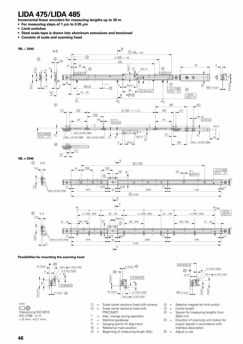
Ô = Scale carrier sections fixed with screwsÕ = Scale carrier sections fixed with
PRECIMET* = Max. change during operationF = Machine guidewayP = Gauging points for alignmentr = Reference mark positions = Beginning of measuring length (ML)
LIDA 475/LIDA 485Incremental linear encoders for measuring lengths up to 30 m• For measuring steps of 1 µm to 0.05 µm• Limit switches• Steel scale-tape is drawn into aluminum extrusions and tensioned• Consists of scale and scanning head
a = Selector magnet for limit switcht = Carrier lengthz = Spacer for measuring lengths from
3040 mm = Direction of scanning unit motion for
output signals in accordance with interface description
Á = Adjust or set
Possibilities for mounting the scanning head
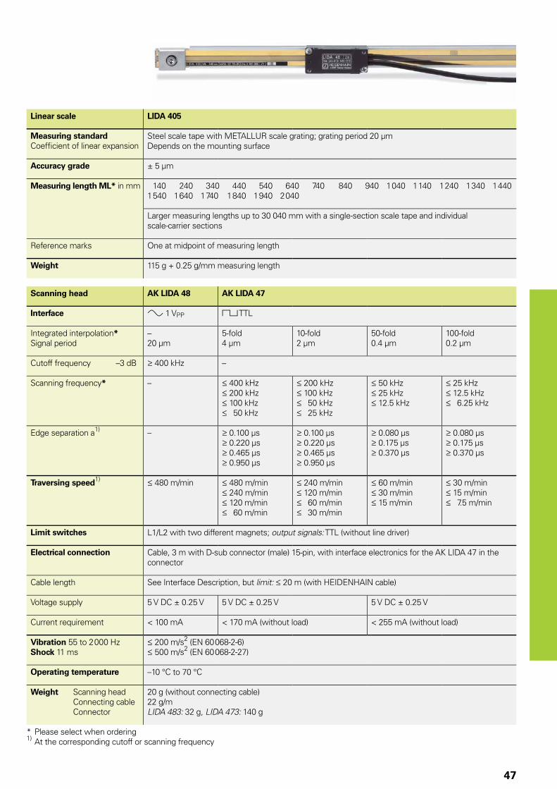
47
Linear scale LIDA 405
Measuring standardCoeffi cient of linear expansion
Steel scale tape with METALLUR scale grating; grating period 20 µmDepends on the mounting surface
Accuracy grade ± 5 µm
Measuring length ML* in mm 140 240 340 440 540 640 740 840 940 1 040 1 140 1 240 1 340 1 4401 540 1 640 1 740 1 840 1 940 2 040
Larger measuring lengths up to 30 040 mm with a single-section scale tape and individual scale-carrier sections
Reference marks One at midpoint of measuring length
Weight 115 g + 0.25 g/mm measuring length
Scanning head AK LIDA 48 AK LIDA 47
Interface » 1 VPP « TTL
Integrated interpolation*Signal period
–20 µm
5-fold4 µm
10-fold2 µm
50-fold0.4 µm
100-fold0.2 µm
Cutoff frequency –3 dB 400 kHz –
Scanning frequency* – 400 kHz 200 kHz 100 kHz 50 kHz
200 kHz 100 kHz 50 kHz 25 kHz
50 kHz 25 kHz 12.5 kHz
25 kHz 12.5 kHz 6.25 kHz
Edge separation a1) – 0.100 µs 0.220 µs 0.465 µs 0.950 µs
0.100 µs 0.220 µs 0.465 µs 0.950 µs
0.080 µs 0.175 µs 0.370 µs
0.080 µs 0.175 µs 0.370 µs
Traversing speed1) 480 m/min 480 m/min 240 m/min 120 m/min 60 m/min
240 m/min 120 m/min 60 m/min 30 m/min
60 m/min 30 m/min 15 m/min
30 m/min 15 m/min 7.5 m/min
Limit switches L1/L2 with two different magnets; output signals: TTL (without line driver)
Electrical connection Cable, 3 m with D-sub connector (male) 15-pin, with interface electronics for the AK LIDA 47 in the connector
Cable length See Interface Description, but limit: 20 m (with HEIDENHAIN cable)
Voltage supply 5 V DC ± 0.25 V 5 V DC ± 0.25 V 5 V DC ± 0.25 V
Current requirement < 100 mA < 170 mA (without load) < 255 mA (without load)
Vibration 55 to 2 000 HzShock 11 ms
200 m/s2 (EN 60 068-2-6) 500 m/s2 (EN 60 068-2-27)
Operating temperature –10 °C to 70 °C
Weight Scanning head Connecting cable Connector
20 g (without connecting cable)22 g/mLIDA 483: 32 g, LIDA 473: 140 g
* Please select when ordering1) At the corresponding cutoff or scanning frequency
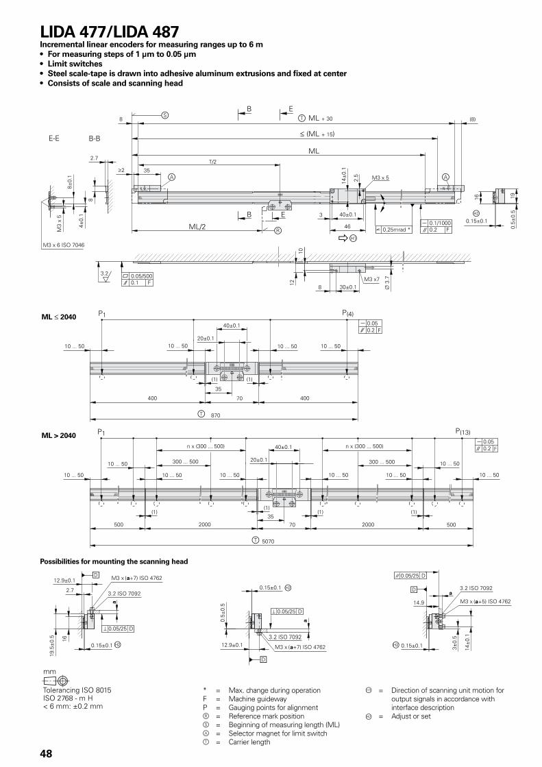
48
Possibilities for mounting the scanning head
* = Max. change during operationF = Machine guidewayP = Gauging points for alignmentr = Reference mark positions = Beginning of measuring length (ML)a = Selector magnet for limit switcht = Carrier length
= Direction of scanning unit motion for output signals in accordance with interface description
Á = Adjust or set
LIDA 477/LIDA 487Incremental linear encoders for measuring ranges up to 6 m• For measuring steps of 1 µm to 0.05 µm• Limit switches• Steel scale-tape is drawn into adhesive aluminum extrusions and fixed at center• Consists of scale and scanning head
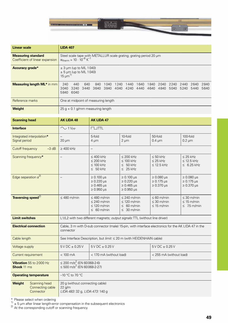
49
Linear scale LIDA 407
Measuring standardCoeffi cient of linear expansion
Steel scale tape with METALLUR scale grating; grating period 20 µmÞtherm � 10 · 10–6 K–1
Accuracy grade* ± 3 µm (up to ML 1 040)± 5 µm (up to ML 1 040)15 µm1)
Measuring length ML* in mm 240 440 640 840 1 040 1 240 1 440 1 640 1 840 2 040 2 240 2 440 2 640 2 8403 040 3 240 3 440 3 640 3 840 4 040 4 240 4 440 4 640 4 840 5 040 5 240 5 440 5 6405 840 6 040
Reference marks One at midpoint of measuring length
Weight 25 g + 0.1 g/mm measuring length
Scanning head AK LIDA 48 AK LIDA 47
Interface » 1 VPP « TTL
Integrated interpolation*Signal period
–20 µm
5-fold4 µm
10-fold2 µm
50-fold0.4 µm
100-fold0.2 µm
Cutoff frequency –3 dB 400 kHz –
Scanning frequency* – 400 kHz 200 kHz 100 kHz 50 kHz
200 kHz 100 kHz 50 kHz 25 kHz
50 kHz 25 kHz 12.5 kHz
25 kHz 12.5 kHz 6.25 kHz
Edge separation a2) – 0.100 µs 0.220 µs 0.465 µs 0.950 µs
0.100 µs 0.220 µs 0.465 µs 0.950 µs
0.080 µs 0.175 µs 0.370 µs
0.080 µs 0.175 µs 0.370 µs
Traversing speed2) 480 m/min 480 m/min 240 m/min 120 m/min 60 m/min
240 m/min 120 m/min 60 m/min 30 m/min
60 m/min 30 m/min 15 m/min
30 m/min 15 m/min 7.5 m/min
Limit switches L1/L2 with two different magnets; output signals: TTL (without line driver)
Electrical connection Cable, 3 m with D-sub connector (male) 15-pin, with interface electronics for the AK LIDA 47 in the connector
Cable length See Interface Description, but limit: 20 m (with HEIDENHAIN cable)
Voltage supply 5 V DC ± 0.25 V 5 V DC ± 0.25 V 5 V DC ± 0.25 V
Current requirement < 100 mA < 170 mA (without load) < 255 mA (without load)
Vibration 55 to 2 000 HzShock 11 ms
200 m/s2 (EN 60 068-2-6) 500 m/s2 (EN 60 068-2-27)
Operating temperature –10 °C to 70 °C
Weight Scanning head Connecting cable Connector
20 g (without connecting cable)22 g/mLIDA 483: 32 g, LIDA 473: 140 g
* Please select when ordering1) ± 5 µm after linear length-error compensation in the subsequent electronics2) At the corresponding cutoff or scanning frequency
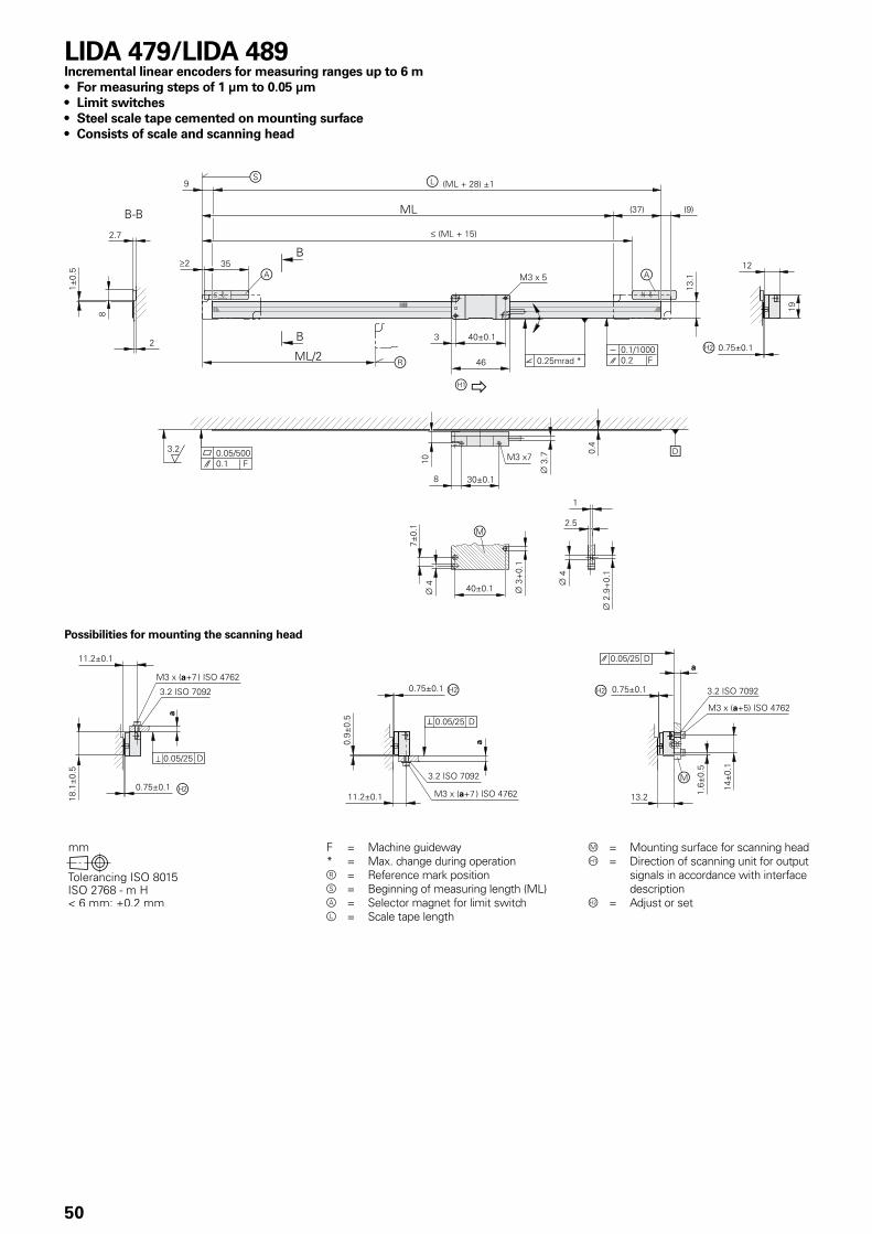
50
F = Machine guideway* = Max. change during operationr = Reference mark positions = Beginning of measuring length (ML)a = Selector magnet for limit switchl = Scale tape length
m = Mounting surface for scanning head = Direction of scanning unit for output
signals in accordance with interface description
Á = Adjust or set
LIDA 479/LIDA 489Incremental linear encoders for measuring ranges up to 6 m• For measuring steps of 1 µm to 0.05 µm• Limit switches• Steel scale tape cemented on mounting surface• Consists of scale and scanning head
Possibilities for mounting the scanning head
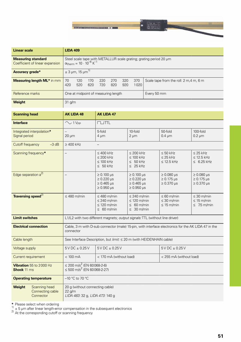
51
Linear scale LIDA 409
Measuring standardCoeffi cient of linear expansion
Steel scale tape with METALLUR scale grating; grating period 20 µmÞtherm � 10 · 10–6 K–1
Accuracy grade* ± 3 µm, 15 µm1)
Measuring length ML* in mm 70 120 170 220 270 320 370420 520 620 720 820 920 1 020
Scale tape from the roll: 2 m,4 m, 6 m
Reference marks One at midpoint of measuring length Every 50 mm
Weight 31 g/m
Scanning head AK LIDA 48 AK LIDA 47
Interface » 1 VPP « TTL
Integrated interpolation*Signal period
–20 µm
5-fold4 µm
10-fold2 µm
50-fold0.4 µm
100-fold0.2 µm
Cutoff frequency –3 dB 400 kHz –
Scanning frequency* – 400 kHz 200 kHz 100 kHz 50 kHz
200 kHz 100 kHz 50 kHz 25 kHz
50 kHz 25 kHz 12.5 kHz
25 kHz 12.5 kHz 6.25 kHz
Edge separation a2) – 0.100 µs 0.220 µs 0.465 µs 0.950 µs
0.100 µs 0.220 µs 0.465 µs 0.950 µs
0.080 µs 0.175 µs 0.370 µs
0.080 µs 0.175 µs 0.370 µs
Traversing speed2) 480 m/min 480 m/min 240 m/min 120 m/min 60 m/min
240 m/min 120 m/min 60 m/min 30 m/min
60 m/min 30 m/min 15 m/min
30 m/min 15 m/min 7.5 m/min
Limit switches L1/L2 with two different magnets; output signals: TTL (without line driver)
Electrical connection Cable, 3 m with D-sub connector (male) 15-pin, with interface electronics for the AK LIDA 47 in the connector
Cable length See Interface Description, but limit: 20 m (with HEIDENHAIN cable)
Voltage supply 5 V DC ± 0.25 V 5 V DC ± 0.25 V 5 V DC ± 0.25 V
Current requirement < 100 mA < 170 mA (without load) < 255 mA (without load)
Vibration 55 to 2 000 HzShock 11 ms
200 m/s2 (EN 60 068-2-6) 500 m/s2 (EN 60 068-2-27)
Operating temperature –10 °C to 70 °C
Weight Scanning head Connecting cable Connector
20 g (without connecting cable)22 g/mLIDA 483: 32 g, LIDA 473: 140 g
* Please select when ordering1) ± 5 µm after linear length-error compensation in the subsequent electronics2) At the corresponding cutoff or scanning frequency
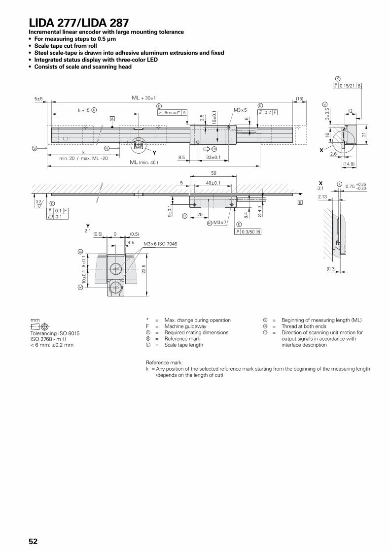
52
* = Max. change during operationF = Machine guidewayk = Required mating dimensionsr = Reference markl = Scale tape length
s = Beginning of measuring length (ML) = Thread at both endsÁ = Direction of scanning unit motion for
output signals in accordance with interface description
LIDA 277/LIDA 287Incremental linear encoder with large mounting tolerance• For measuring steps to 0.5 µm• Scale tape cut from roll• Steel scale-tape is drawn into adhesive aluminum extrusions and fixed• Integrated status display with three-color LED• Consists of scale and scanning head
Reference mark:k = Any position of the selected reference mark starting from the beginning of the measuring length
(depends on the length of cut)
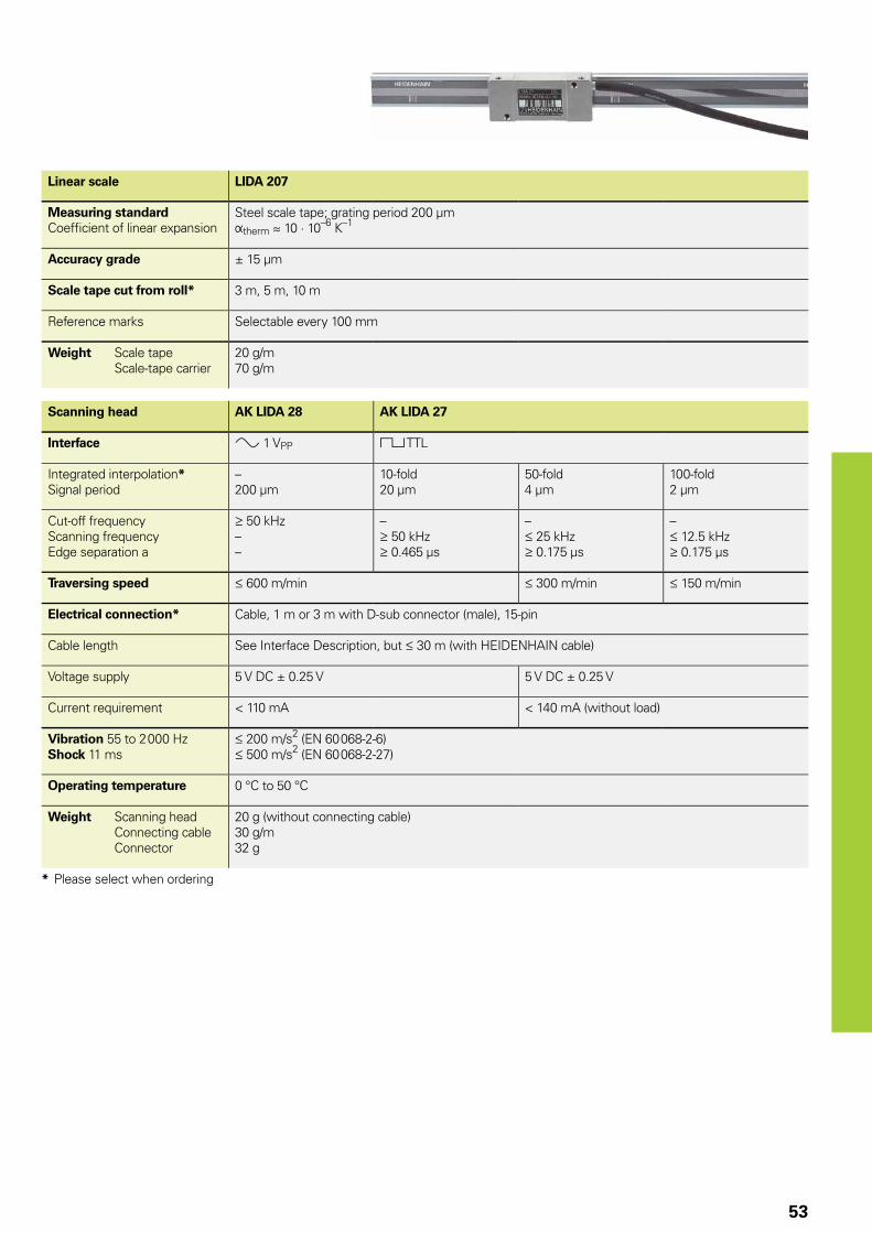
53
Linear scale LIDA 207
Measuring standardCoeffi cient of linear expansion
Steel scale tape; grating period 200 µmÞtherm � 10 · 10–6 K–1
Accuracy grade ± 15 µm
Scale tape cut from roll* 3 m, 5 m, 10 m
Reference marks Selectable every 100 mm
Weight Scale tape Scale-tape carrier
20 g/m70 g/m
Scanning head AK LIDA 28 AK LIDA 27
Interface » 1 VPP « TTL
Integrated interpolation*Signal period
–200 µm
10-fold20 µm
50-fold4 µm
100-fold2 µm
Cut-off frequencyScanning frequencyEdge separation a
50 kHz––
– 50 kHz 0.465 µs
– 25 kHz 0.175 µs
– 12.5 kHz 0.175 µs
Traversing speed 600 m/min 300 m/min 150 m/min
Electrical connection* Cable, 1 m or 3 m with D-sub connector (male), 15-pin
Cable length See Interface Description, but 30 m (with HEIDENHAIN cable)
Voltage supply 5 V DC ± 0.25 V 5 V DC ± 0.25 V
Current requirement < 110 mA < 140 mA (without load)
Vibration 55 to 2 000 HzShock 11 ms
200 m/s2 (EN 60 068-2-6) 500 m/s2 (EN 60 068-2-27)
Operating temperature 0 °C to 50 °C
Weight Scanning head Connecting cable Connector
20 g (without connecting cable)30 g/m32 g
* Please select when ordering
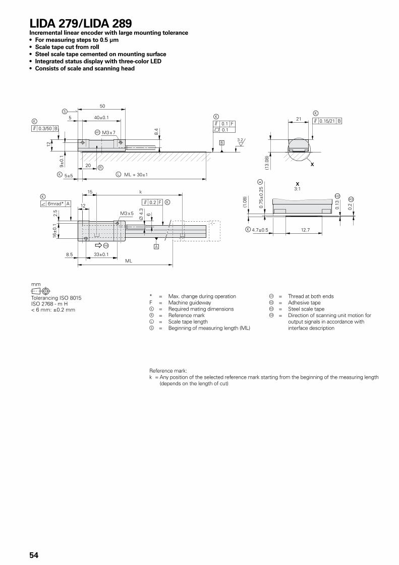
54
* = Max. change during operationF = Machine guidewayk = Required mating dimensionsr = Reference markl = Scale tape lengths = Beginning of measuring length (ML)
= Thread at both endsÁ = Adhesive tape = Steel scale tapeà = Direction of scanning unit motion for
output signals in accordance with interface description
LIDA 279/LIDA 289Incremental linear encoder with large mounting tolerance• For measuring steps to 0.5 µm• Scale tape cut from roll• Steel scale tape cemented on mounting surface• Integrated status display with three-color LED• Consists of scale and scanning head
Reference mark:k = Any position of the selected reference mark starting from the beginning of the measuring length
(depends on the length of cut)
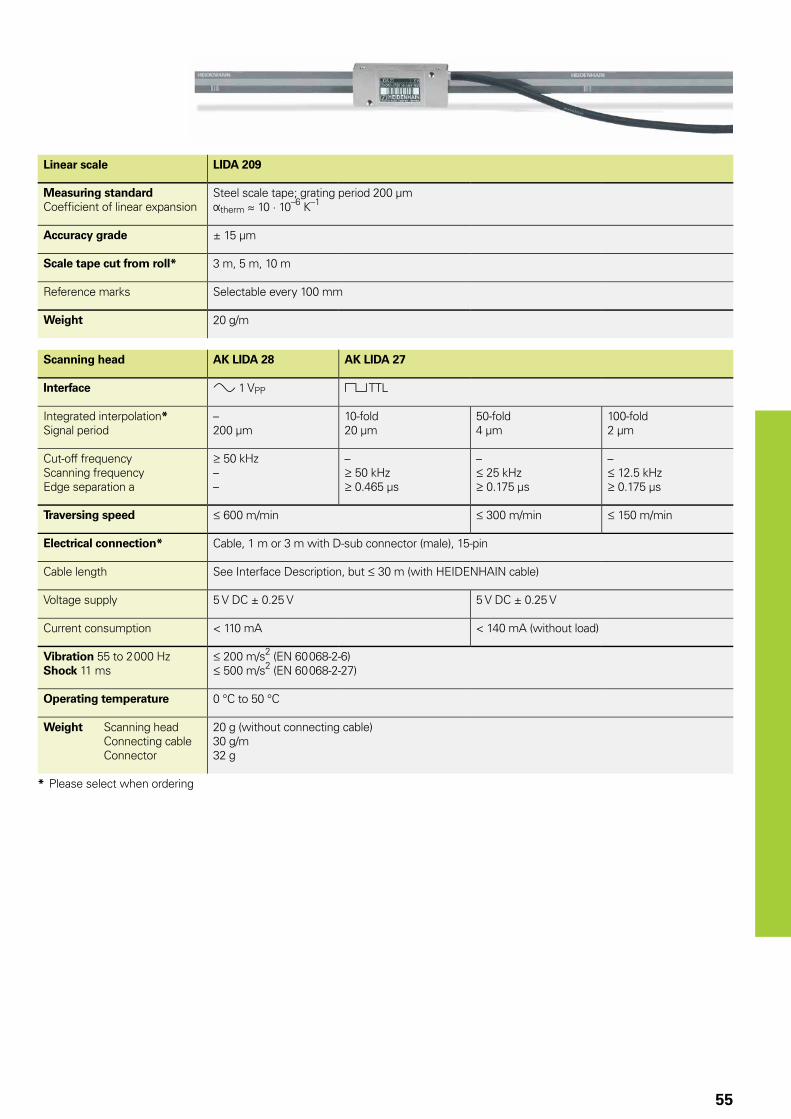
55
Linear scale LIDA 209
Measuring standardCoeffi cient of linear expansion
Steel scale tape; grating period 200 µmÞtherm � 10 · 10–6 K–1
Accuracy grade ± 15 µm
Scale tape cut from roll* 3 m, 5 m, 10 m
Reference marks Selectable every 100 mm
Weight 20 g/m
Scanning head AK LIDA 28 AK LIDA 27
Interface » 1 VPP « TTL
Integrated interpolation*Signal period
–200 µm
10-fold20 µm
50-fold4 µm
100-fold2 µm
Cut-off frequencyScanning frequencyEdge separation a
50 kHz––
– 50 kHz 0.465 µs
– 25 kHz 0.175 µs
– 12.5 kHz 0.175 µs
Traversing speed 600 m/min 300 m/min 150 m/min
Electrical connection* Cable, 1 m or 3 m with D-sub connector (male), 15-pin
Cable length See Interface Description, but 30 m (with HEIDENHAIN cable)
Voltage supply 5 V DC ± 0.25 V 5 V DC ± 0.25 V
Current consumption < 110 mA < 140 mA (without load)
Vibration 55 to 2 000 HzShock 11 ms
200 m/s2 (EN 60 068-2-6) 500 m/s2 (EN 60 068-2-27)
Operating temperature 0 °C to 50 °C
Weight Scanning head Connecting cable Connector
20 g (without connecting cable)30 g/m32 g
* Please select when ordering
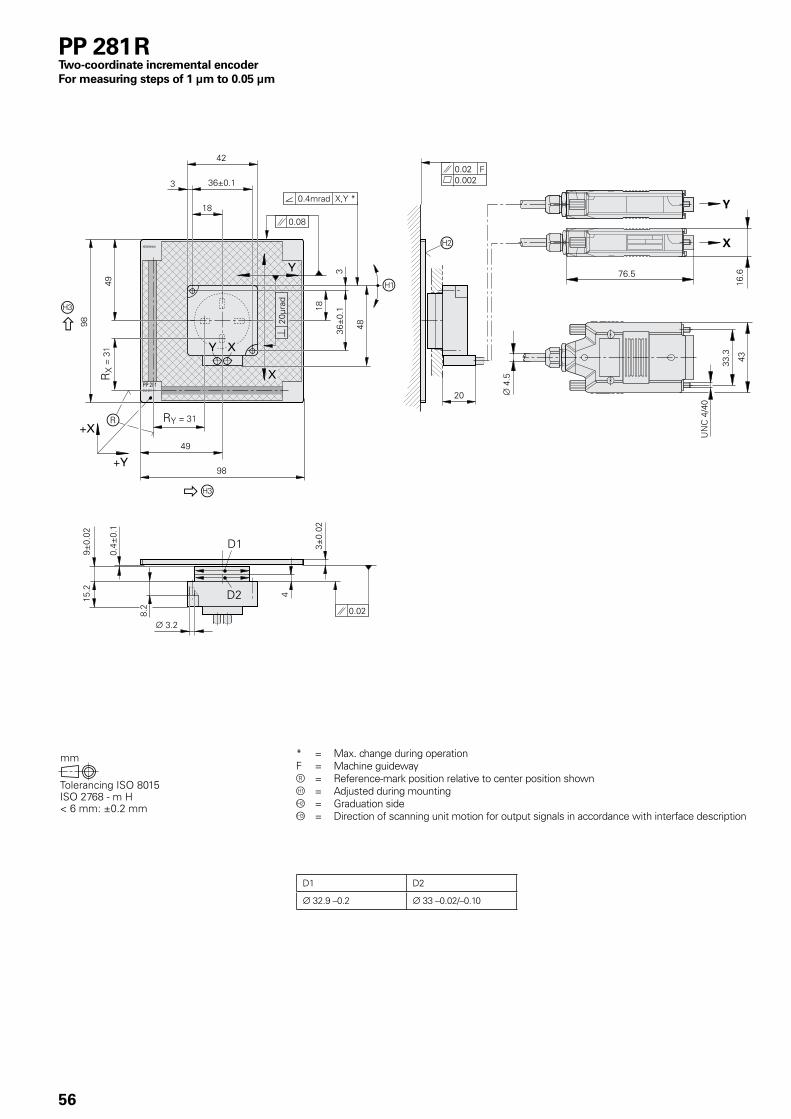
56
PP 281 RTwo-coordinate incremental encoder For measuring steps of 1 µm to 0.05 µm
* = Max. change during operationF = Machine guidewayr = Reference-mark position relative to center position shown = Adjusted during mountingÁ = Graduation side = Direction of scanning unit motion for output signals in accordance with interface description
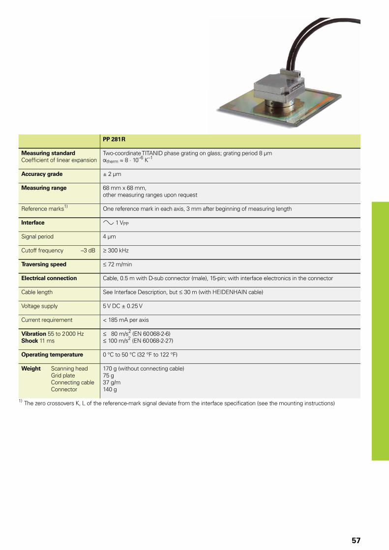
57
PP 281 R
Measuring standardCoeffi cient of linear expansion
Two-coordinate TITANID phase grating on glass; grating period 8 µmÞtherm � 8 · 10–6 K–1
Accuracy grade ± 2 µm
Measuring range 68 mm x 68 mm, other measuring ranges upon request
Reference marks1) One reference mark in each axis, 3 mm after beginning of measuring length
Interface » 1 VPP
Signal period 4 µm
Cutoff frequency –3 dB 300 kHz
Traversing speed 72 m/min
Electrical connection Cable, 0.5 m with D-sub connector (male), 15-pin; with interface electronics in the connector
Cable length See Interface Description, but 30 m (with HEIDENHAIN cable)
Voltage supply 5 V DC ± 0.25 V
Current requirement < 185 mA per axis
Vibration 55 to 2 000 HzShock 11 ms
80 m/s2 (EN 60 068-2-6) 100 m/s2 (EN 60 068-2-27)
Operating temperature 0 °C to 50 °C (32 °F to 122 °F)
Weight Scanning head Grid plate Connecting cable Connector
170 g (without connecting cable)75 g37 g/m140 g
1) The zero crossovers K, L of the reference-mark signal deviate from the interface specifi cation (see the mounting instructions)
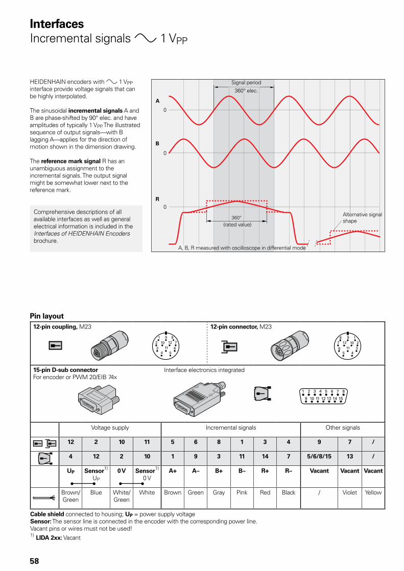
58
InterfacesIncremental signals » 1 VPP
HEIDENHAIN encoders with » 1 VPP interface provide voltage signals that can be highly interpolated.
The sinusoidal incremental signals A and B are phase-shifted by 90° elec. and have amplitudes of typically 1 VPP. The illustrated sequence of output signals—with B lagging A—applies for the direction of motion shown in the dimension drawing.
The reference mark signal R has an unambiguous assignment to the incremental signals. The output signal might be somewhat lower next to the reference mark.
Comprehensive descriptions of all available interfaces as well as general electrical information is included in the Interfaces of HEIDENHAIN Encoders brochure.
Pin layout12-pin coupling, M23 12-pin connector, M23
15-pin D-sub connectorFor encoder or PWM 20/EIB 74x
Interface electronics integrated
Voltage supply Incremental signals Other signals
12 2 10 11 5 6 8 1 3 4 9 7 /
4 12 2 10 1 9 3 11 14 7 5/6/8/15 13 /
UP Sensor1)
UP
0 V Sensor1)
0 VA+ A– B+ B– R+ R– Vacant Vacant Vacant
Brown/Green
Blue White/Green
White Brown Green Gray Pink Red Black / Violet Yellow
Cable shield connected to housing; UP = power supply voltageSensor: The sensor line is connected in the encoder with the corresponding power line.Vacant pins or wires must not be used!1) LIDA 2xx: Vacant
Signal period360° elec.
(rated value)
A, B, R measured with oscilloscope in differential mode
Alternative signal shape
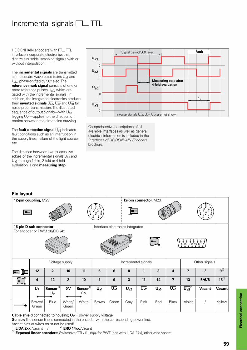
59
Ele
ctri
cal c
on
nec
tio
n
Incremental signals « TTL
HEIDENHAIN encoders with « TTL interface incorporate electronics that digitize sinusoidal scanning signals with or without interpolation.
The incremental signals are transmitted as the square-wave pulse trains Ua1 and Ua2, phase-shifted by 90° elec. The reference mark signal consists of one or more reference pulses Ua0, which are gated with the incremental signals. In addition, the integrated electronics produce their inverted signals ¢, £ and ¤ for noise-proof transmission. The illustrated sequence of output signals—with Ua2 lagging Ua1—applies to the direction of motion shown in the dimension drawing.
The fault detection signal ¥ indicates fault conditions such as an interruption in the supply lines, failure of the light source, etc.
The distance between two successive edges of the incremental signals Ua1 and Ua2 through 1-fold, 2-fold or 4-fold evaluation is one measuring step.
Comprehensive descriptions of all available interfaces as well as general electrical information is included in the Interfaces of HEIDENHAIN Encoders brochure.
Pin layout12-pin coupling, M23 12-pin connector, M23
15-pin D-sub connectorFor encoder or PWM 20/EIB 74x
Interface electronics integrated
Voltage supply Incremental signals Other signals
12 2 10 11 5 6 8 1 3 4 7 / 93)
4 12 2 10 1 9 3 11 14 7 13 5/6/8 153)
UP Sensor1)
UP
0 V Sensor1)
0 VUa1 ¢ Ua2 £ Ua0 ¤ ¥2) Vacant Vacant
Brown/Green
Blue White/Green
White Brown Green Gray Pink Red Black Violet / Yellow
Cable shield connected to housing; UP = power supply voltageSensor: The sensor line is connected in the encoder with the corresponding power line.Vacant pins or wires must not be used!1) LIDA 2xx: Vacant / 2) ERO 14xx: Vacant3) Exposed linear encoders: Switchover TTL/11 µAPP for PWT (not with LIDA 27x), otherwise vacant
Signal period 360° elec. Fault
Measuring step after 4-fold evaluation
Inverse signals ¢, £, ¤ are not shown
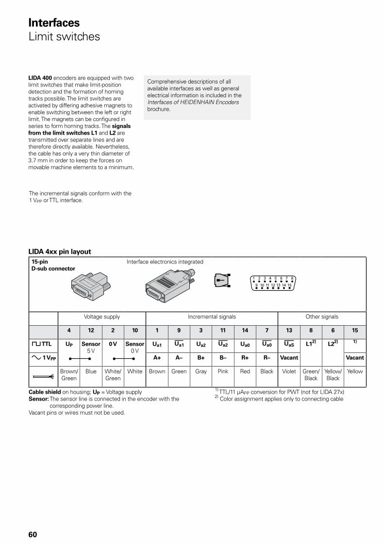
60
InterfacesLimit switches
LIDA 400 encoders are equipped with two limit switches that make limit-position detection and the formation of homing tracks possible. The limit switches are activated by differing adhesive magnets to enable switching between the left or right limit. The magnets can be configured in series to form homing tracks. The signals from the limit switches L1 and L2 are transmitted over separate lines and are therefore directly available. Nevertheless, the cable has only a very thin diameter of 3.7 mm in order to keep the forces on movable machine elements to a minimum.
LIDA 4xx pin layout15-pin D-sub connector
Interface electronics integrated
Voltage supply Incremental signals Other signals
4 12 2 10 1 9 3 11 14 7 13 8 6 15
« TTL UP Sensor5 V
0 V Sensor0 V
Ua1 ¢ Ua2 £ Ua0 ¤ ¥ L12) L22) 1)
» 1 VPP A+ A– B+ B– R+ R– Vacant Vacant
Brown/Green
Blue White/Green
White Brown Green Gray Pink Red Black Violet Green/Black
Yellow/Black
Yellow
Cable shield on housing; UP = Voltage supplySensor: The sensor line is connected in the encoder with the
corresponding power line.Vacant pins or wires must not be used.
1) TTL/11 µAPP conversion for PWT (not for LIDA 27x)2) Color assignment applies only to connecting cable
Comprehensive descriptions of all available interfaces as well as general electrical information is included in the Interfaces of HEIDENHAIN Encoders brochure.
The incremental signals conform with the 1 VPP or TTL interface.
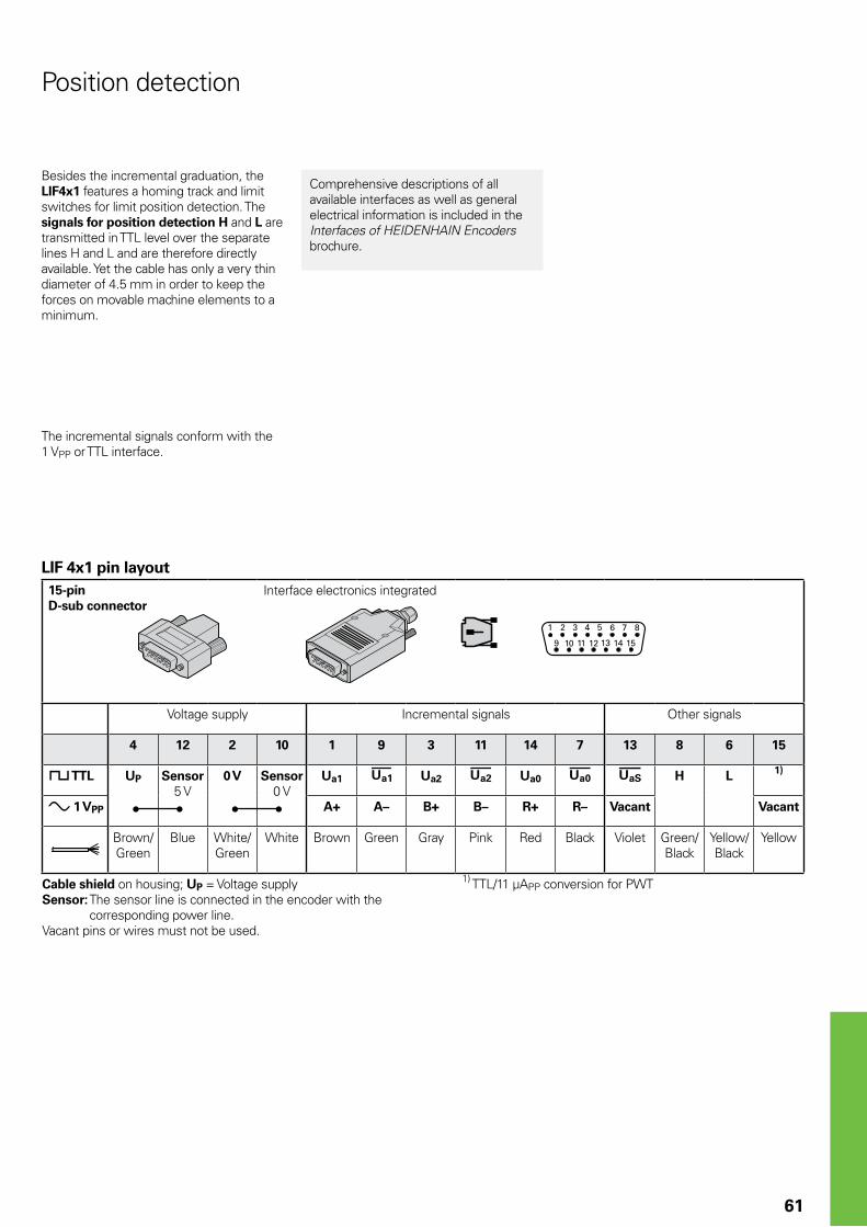
61
Position detection
Besides the incremental graduation, the LIF4x1 features a homing track and limit switches for limit position detection. The signals for position detection H and L are transmitted in TTL level over the separate lines H and L and are therefore directly available. Yet the cable has only a very thin diameter of 4.5 mm in order to keep the forces on movable machine elements to a minimum.
LIF 4x1 pin layout15-pin D-sub connector
Interface electronics integrated
Voltage supply Incremental signals Other signals
4 12 2 10 1 9 3 11 14 7 13 8 6 15
« TTL UP Sensor5 V
0 V Sensor0 V
Ua1 ¢ Ua2 £ Ua0 ¤ ¥ H L 1)
» 1 VPP A+ A– B+ B– R+ R– Vacant Vacant
Brown/Green
Blue White/Green
White Brown Green Gray Pink Red Black Violet Green/Black
Yellow/Black
Yellow
Cable shield on housing; UP = Voltage supplySensor: The sensor line is connected in the encoder with the
corresponding power line.Vacant pins or wires must not be used.
1) TTL/11 µAPP conversion for PWT
Comprehensive descriptions of all available interfaces as well as general electrical information is included in the Interfaces of HEIDENHAIN Encoders brochure.
The incremental signals conform with the 1 VPP or TTL interface.
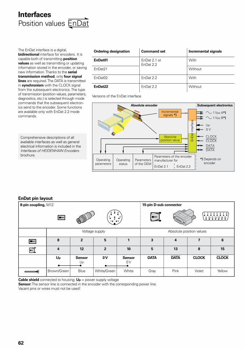
62
InterfacesPosition values
The EnDat interface is a digital, bidirectional interface for encoders. It is capable both of transmitting position values as well as transmitting or updating information stored in the encoder, or saving new information. Thanks to the serial transmission method, only four signal lines are required. The DATA is transmitted in synchronism with the CLOCK signal from the subsequent electronics. The type of transmission (position values, parameters, diagnostics, etc.) is selected through mode commands that the subsequent electron-ics send to the encoder. Some functions are available only with EnDat 2.2 mode commands.
Ordering designation Command set Incremental signals
EnDat01 EnDat 2.1 or EnDat 2.2
With
EnDat21 Without
EnDat02 EnDat 2.2 With
EnDat22 EnDat 2.2 Without
Versions of the EnDat interface
Absolute encoder Subsequent electronics
» 1 VPP A*)
» 1 VPP B*)
Operating parameters
Operating status
Parameters of the OEM
Parameters of the encoder manufacturer for
EnDat 2.1 EnDat 2.2
*) Depends on encoder
Absolute position value En
Dat
inte
rfac
e
Incremental signals *)
Comprehensive descriptions of all available interfaces as well as general electrical information is included in the Interfaces of HEIDENHAIN Encoders brochure.
EnDat pin layout8-pin coupling, M12 15-pin D-sub connector
Voltage supply Absolute position values
8 2 5 1 3 4 7 6
4 12 2 10 5 13 8 15
UP SensorUP
0 V Sensor0 V
DATA DATA CLOCK CLOCK
Brown/Green Blue White/Green White Gray Pink Violet Yellow
Cable shield connected to housing; UP = power supply voltageSensor: The sensor line is connected in the encoder with the corresponding power line.Vacant pins or wires must not be used!
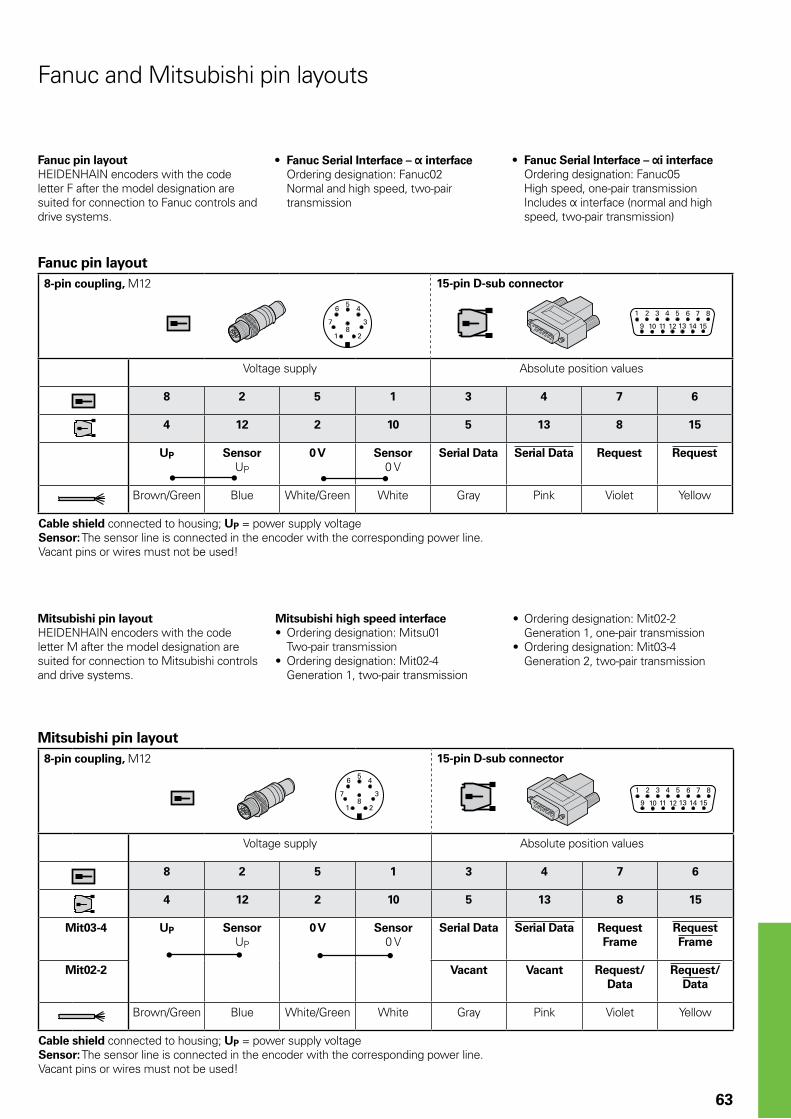
63
Fanuc pin layoutHEIDENHAIN encoders with the code letter F after the model designation are suited for connection to Fanuc controls and drive systems.
Fanuc and Mitsubishi pin layouts
Mitsubishi pin layoutHEIDENHAIN encoders with the code letter M after the model designation are suited for connection to Mitsubishi controls and drive systems.
• Fanuc Serial Interface – interface Ordering designation: Fanuc02 Normal and high speed, two-pair transmission
Mitsubishi high speed interface• Ordering designation: Mitsu01
Two-pair transmission• Ordering designation: Mit02-4
Generation 1, two-pair transmission
Mitsubishi pin layout8-pin coupling, M12 15-pin D-sub connector
Voltage supply Absolute position values
8 2 5 1 3 4 7 6
4 12 2 10 5 13 8 15
Mit03-4 UP SensorUP
0 V Sensor0 V
Serial Data Serial Data RequestFrame
RequestFrame
Mit02-2 Vacant Vacant Request/Data
Request/Data
Brown/Green Blue White/Green White Gray Pink Violet Yellow
Cable shield connected to housing; UP = power supply voltageSensor: The sensor line is connected in the encoder with the corresponding power line.Vacant pins or wires must not be used!
Fanuc pin layout8-pin coupling, M12 15-pin D-sub connector
Voltage supply Absolute position values
8 2 5 1 3 4 7 6
4 12 2 10 5 13 8 15
UP SensorUP
0 V Sensor0 V
Serial Data Serial Data Request Request
Brown/Green Blue White/Green White Gray Pink Violet Yellow
Cable shield connected to housing; UP = power supply voltageSensor: The sensor line is connected in the encoder with the corresponding power line.Vacant pins or wires must not be used!
• Fanuc Serial Interface – i interface Ordering designation: Fanuc05 High speed, one-pair transmission Includes Þ interface (normal and high speed, two-pair transmission)
• Ordering designation: Mit02-2 Generation 1, one-pair transmission
• Ordering designation: Mit03-4 Generation 2, two-pair transmission
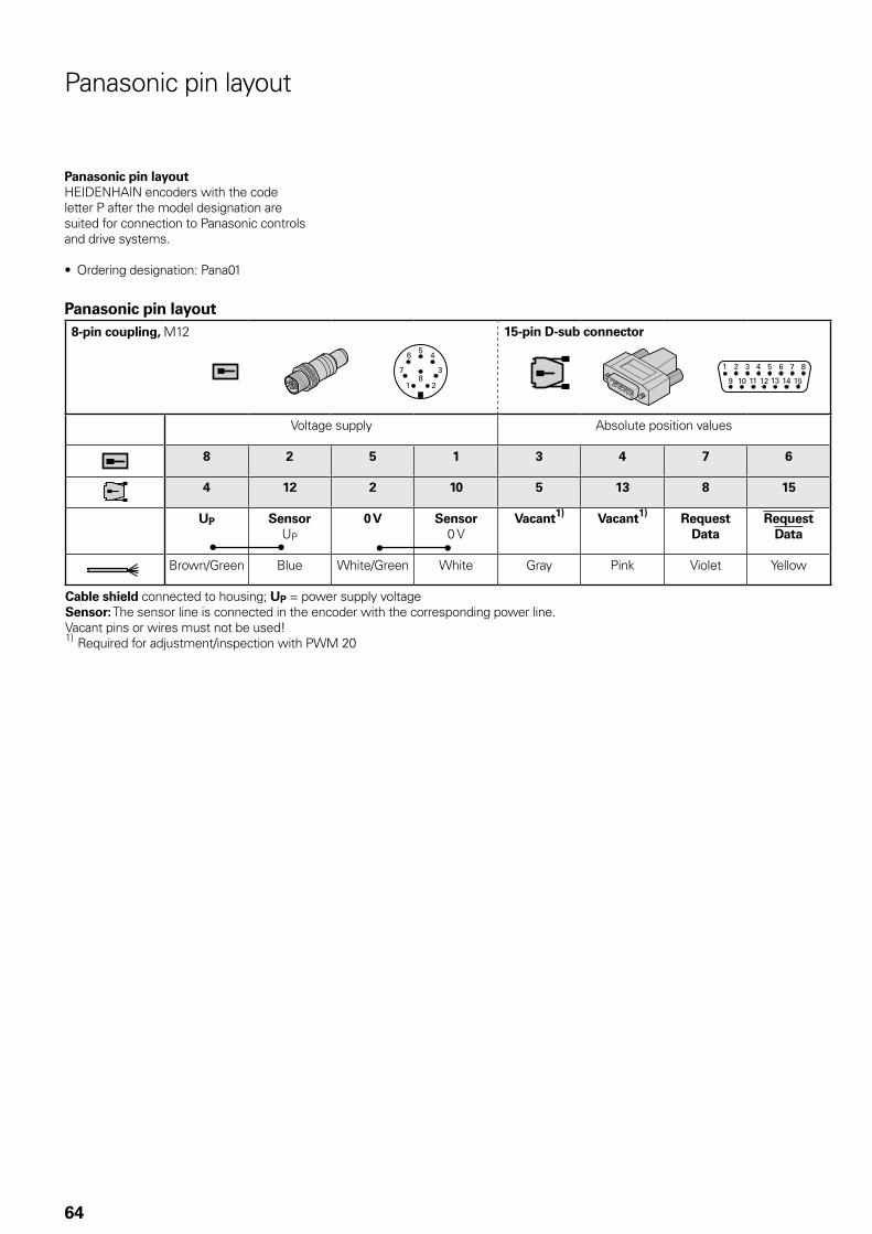
64
Panasonic pin layout
Panasonic pin layoutHEIDENHAIN encoders with the code letter P after the model designation are suited for connection to Panasonic controls and drive systems.
• Ordering designation: Pana01
Panasonic pin layout8-pin coupling, M12 15-pin D-sub connector
Voltage supply Absolute position values
8 2 5 1 3 4 7 6
4 12 2 10 5 13 8 15
UP SensorUP
0 V Sensor0 V
Vacant1) Vacant1) RequestData
RequestData
Brown/Green Blue White/Green White Gray Pink Violet Yellow
Cable shield connected to housing; UP = power supply voltageSensor: The sensor line is connected in the encoder with the corresponding power line.Vacant pins or wires must not be used!1) Required for adjustment/inspection with PWM 20
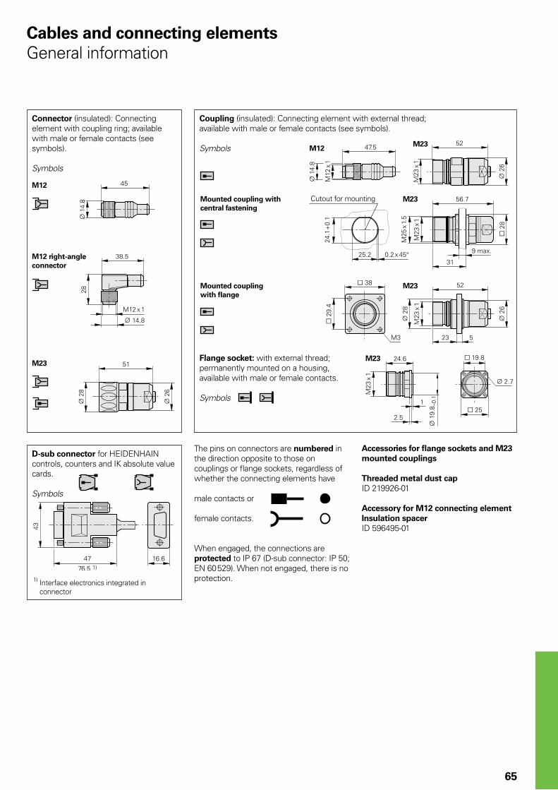
M23
M23
M23
M23
M12
M12
M23
65
The pins on connectors are numbered in the direction opposite to those on couplings or flange sockets, regardless of whether the connecting elements have
male contacts or
female contacts.
When engaged, the connections are protected to IP 67 (D-sub connector: IP 50; EN 60 529). When not engaged, there is no protection.
Connector (insulated): Connecting element with coupling ring; available with male or female contacts (see symbols).
Symbols
Coupling (insulated): Connecting element with external thread; available with male or female contacts (see symbols).
Symbols
D-sub connector for HEIDENHAIN controls, counters and IK absolute value cards.
Symbols
Accessories for flange sockets and M23 mounted couplings
Threaded metal dust capID 219926-01
Accessory for M12 connecting elementInsulation spacerID 596495-01
Mounted coupling with central fastening
Mounted coupling with flange
1) Interface electronics integrated in connector
M12 right-angle connector
Flange socket: with external thread; permanently mounted on a housing, available with male or female contacts.
Symbols
Cables and connecting elementsGeneral information
Cutout for mounting
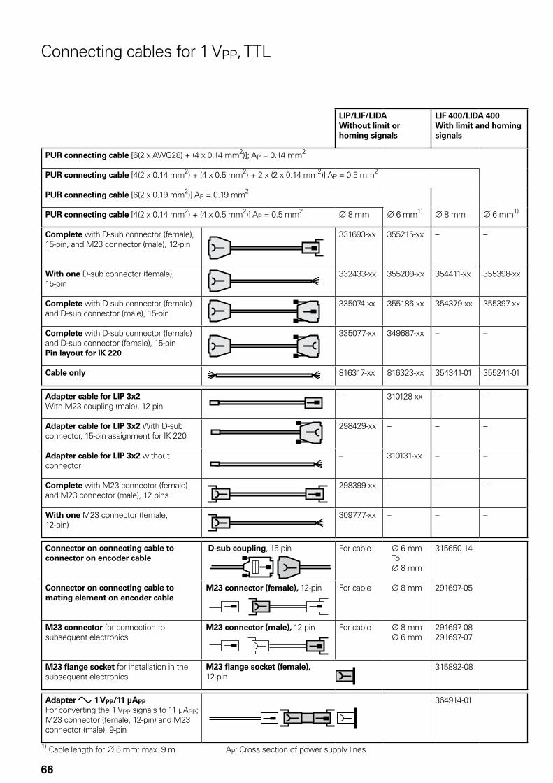
66
Connecting cables for 1 VPP, TTL
LIP/LIF/LIDAWithout limit or homing signals
LIF 400/LIDA 400With limit and homing signals
PUR connecting cable [6(2 x AWG28) + (4 x 0.14 mm2)]; AP = 0.14 mm2
PUR connecting cable [4(2 x 0.14 mm2) + (4 x 0.5 mm2) + 2 x (2 x 0.14 mm2)] AP = 0.5 mm2
PUR connecting cable [6(2 x 0.19 mm2)] AP = 0.19 mm2
PUR connecting cable [4(2 x 0.14 mm2) + (4 x 0.5 mm2)] AP = 0.5 mm2 ¬ 8 mm ¬ 6 mm1) ¬ 8 mm ¬ 6 mm1)
Complete with D-sub connector (female), 15-pin, and M23 connector (male), 12-pin
331693-xx 355215-xx – –
With one D-sub connector (female), 15-pin
332433-xx 355209-xx 354411-xx 355398-xx
Complete with D-sub connector (female) and D-sub connector (male), 15-pin
335074-xx 355186-xx 354379-xx 355397-xx
Complete with D-sub connector (female) and D-sub connector (female), 15-pinPin layout for IK 220
335077-xx 349687-xx – –
Cable only 816317-xx 816323-xx 354341-01 355241-01
Adapter cable for LIP 3x2With M23 coupling (male), 12-pin
– 310128-xx – –
Adapter cable for LIP 3x2 With D-sub connector, 15-pin assignment for IK 220
298429-xx – – –
Adapter cable for LIP 3x2 without connector
– 310131-xx – –
Complete with M23 connector (female) and M23 connector (male), 12 pins
298399-xx – – –
With one M23 connector (female, 12-pin)
309777-xx – – –
Connector on connecting cable to connector on encoder cable
D-sub coupling, 15-pin For cable ¬ 6 mm To ¬ 8 mm
315650-14
Connector on connecting cable to mating element on encoder cable
M23 connector (female), 12-pin For cable ¬ 8 mm 291697-05
M23 connector for connection to subsequent electronics
M23 connector (male), 12-pin For cable ¬ 8 mm ¬ 6 mm
291697-08291697-07
M23 flange socket for installation in the subsequent electronics
M23 flange socket (female), 12-pin
315892-08
Adapter » 1 VPP/11 µAPPFor converting the 1 VPP signals to 11 µAPP; M23 connector (female, 12-pin) and M23 connector (male), 9-pin
364914-01
1) Cable length for ¬ 6 mm: max. 9 m AP: Cross section of power supply lines
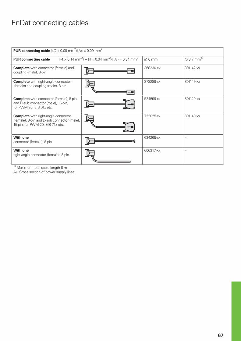
67
EnDat connecting cables
PUR connecting cable [4(2 x 0.09 mm2)] AP = 0.09 mm2
PUR connecting cable [(4 × 0.14 mm2) + (4 × 0.34 mm2)]; AP = 0.34 mm2 6 mm 3.7 mm1)
Complete with connector (female) and coupling (male), 8-pin
368330-xx 801142-xx
Complete with right-angle connector (female) and coupling (male), 8-pin
373289-xx 801149-xx
Complete with connector (female), 8-pin and D-sub connector (male), 15-pin, for PWM 20, EIB 74x etc.
524599-xx 801129-xx
Complete with right-angle connector (female), 8-pin and D-sub connector (male), 15-pin, for PWM 20, EIB 74x etc.
722025-xx 801140-xx
With one connector (female), 8-pin
634265-xx –
With one right-angle connector (female), 8-pin
606317-xx –
1) Maximum total cable length 6 mAP: Cross section of power supply lines
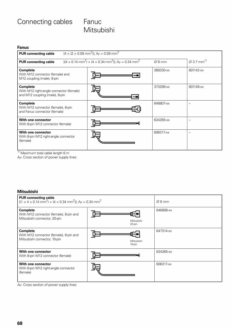
68
Connecting cables Fanuc Mitsubishi
FanucPUR connecting cable [4 × (2 × 0.09 mm2)]; AP = 0.09 mm2
PUR connecting cable [(4 × 0.14 mm2) + (4 × 0.34 mm2)]; AP = 0.34 mm2 ¬ 6 mm ¬ 3.7 mm1)
CompleteWith M12 connector (female) and M12 coupling (male), 8-pin
368330-xx 801142-xx
CompleteWith M12 right-angle connector (female) and M12 coupling (male), 8-pin
373289-xx 801149-xx
CompleteWith M12 connector (female), 8-pin and Fanuc connector (female)
646807-xx –
With one connectorWith 8-pin M12 connector (female)
634265-xx –
With one connectorWith 8-pin M12 right-angle connector (female)
606317-xx –
1) Maximum total cable length 6 mAP: Cross section of power supply lines
MitsubishiPUR connecting cable [(1 × 4 × 0.14 mm2) + (4 × 0.34 mm2)]; AP = 0.34 mm2 ¬ 6 mm
CompleteWith M12 connector (female), 8-pin and Mitsubishi connector, 20-pin
646806-xx
CompleteWith M12 connector (female), 8-pin and Mitsubishi connector, 10-pin
647314-xx
With one connectorWith 8-pin M12 connector (female)
634265-xx
With one connectorWith 8-pin M12 right-angle connector (female)
606317-xx
AP: Cross section of power supply lines
Mitsubishi20-pin
Mitsubishi10-pin
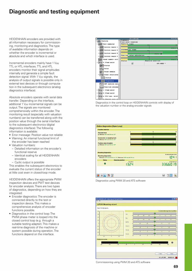
69
Diagnostic and testing equipment
Diagnostics in the control loop on HEIDENHAIN controls with display of the valuation number or the analog encoder signals
Diagnostics using PWM 20 and ATS software
Commissioning using PWM 20 and ATS software
HEIDENHAIN encoders are provided with all information necessary for commission-ing, monitoring and diagnostics. The type of available information depends on whether the encoder is incremental or absolute and which interface is used.
Incremental encoders mainly have 1 VPP, TTL or HTL interfaces. TTL and HTL encoders monitor their signal amplitudes internally and generate a simple fault detection signal. With 1 VPP signals, the analysis of output signals is possible only in external test devices or through computa-tion in the subsequent electronics (analog diagnostics interface).
Absolute encoders operate with serial data transfer. Depending on the interface, additional 1 VPP incremental signals can be output. The signals are monitored comprehensively within the encoder. The monitoring result (especially with valuation numbers) can be transferred along with the position value through the serial interface to the subsequent electronics (digital diagnostics interface). The following information is available:• Error message: Position value not reliable• Warning: An internal functional limit of
the encoder has been reached• Valuation numbers:
– Detailed information on the encoder’s functional reserve
– Identical scaling for all HEIDENHAIN encoders
– Cyclic output is possibleThis enables the subsequent electronics to evaluate the current status of the encoder at little cost even in closed-loop mode.
HEIDENHAIN offers the appropriate PWM inspection devices and PWT test devices for encoder analysis. There are two types of diagnostics, depending on how they are integrated:• Encoder diagnostics: The encoder is
connected directly to the test or inspection device. This makes a comprehensive analysis of encoder functions possible.
• Diagnostics in the control loop: The PWM phase meter is looped into the closed control loop (e.g. through a suitable testing adapter). This makes a real-time diagnosis of the machine or system possible during operation. The functions depend on the interface.
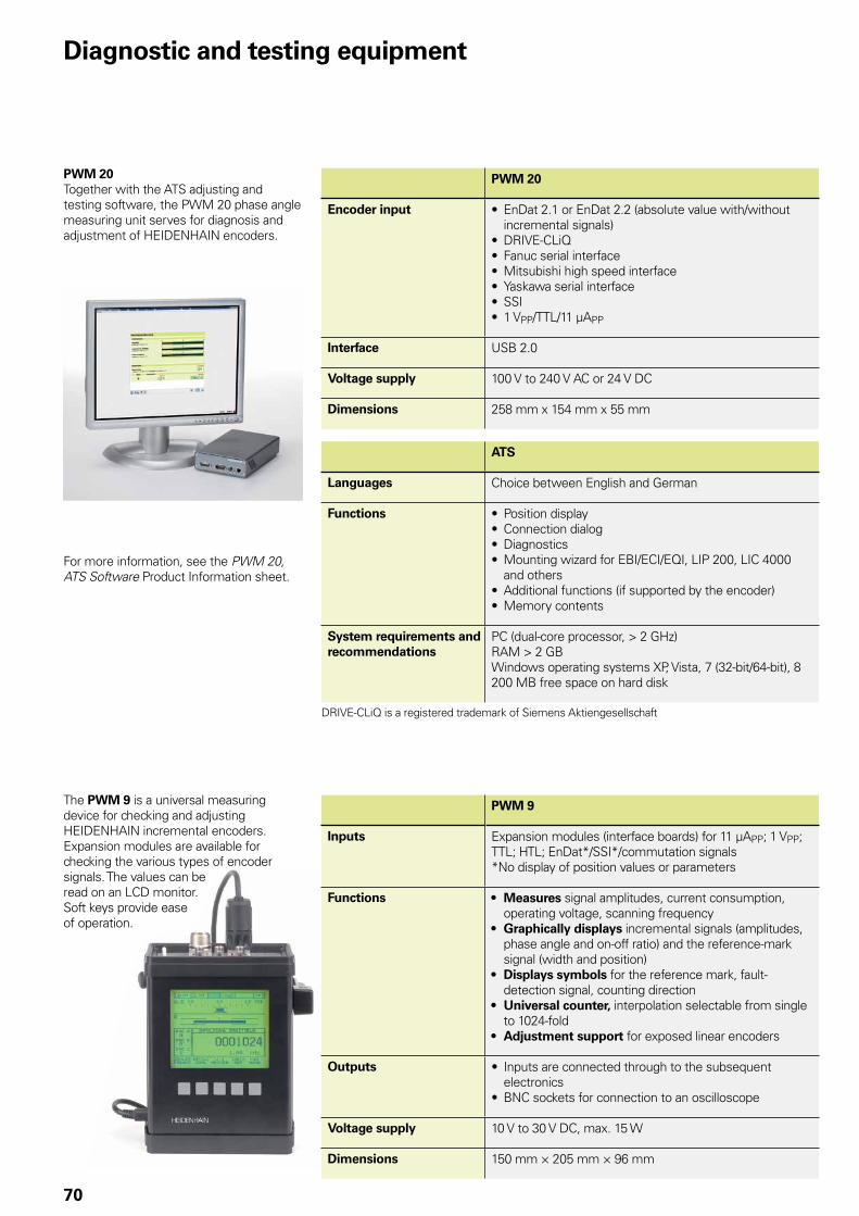
70
Diagnostic and testing equipment
PWM 20Together with the ATS adjusting and testing software, the PWM 20 phase angle measuring unit serves for diagnosis and adjustment of HEIDENHAIN encoders.
PWM 20
Encoder input • EnDat 2.1 or EnDat 2.2 (absolute value with/without incremental signals)
• DRIVE-CLiQ• Fanuc serial interface• Mitsubishi high speed interface• Yaskawa serial interface• SSI• 1 VPP/TTL/11 µAPP
Interface USB 2.0
Voltage supply 100 V to 240 V AC or 24 V DC
Dimensions 258 mm x 154 mm x 55 mm
ATS
Languages Choice between English and German
Functions • Position display• Connection dialog• Diagnostics• Mounting wizard for EBI/ECI/EQI, LIP 200, LIC 4000
and others• Additional functions (if supported by the encoder)• Memory contents
System requirements and recommendations
PC (dual-core processor, > 2 GHz)RAM > 2 GBWindows operating systems XP, Vista, 7 (32-bit/64-bit), 8200 MB free space on hard disk
DRIVE-CLiQ is a registered trademark of Siemens Aktiengesellschaft
The PWM 9 is a universal measuring device for checking and adjusting HEIDENHAIN incremental encoders. Expansion modules are available for checking the various types of encoder signals. The values can be read on an LCD monitor. Soft keys provide ease of operation.
PWM 9
Inputs Expansion modules (interface boards) for 11 µAPP; 1 VPP; TTL; HTL; EnDat*/SSI*/commutation signals*No display of position values or parameters
Functions • Measures signal amplitudes, current consumption, operating voltage, scanning frequency
• Graphically displays incremental signals (amplitudes, phase angle and on-off ratio) and the reference-mark signal (width and position)
• Displays symbols for the reference mark, fault-detection signal, counting direction
• Universal counter, interpolation selectable from single to 1024-fold
• Adjustment support for exposed linear encoders
Outputs • Inputs are connected through to the subsequent electronics
• BNC sockets for connection to an oscilloscope
Voltage supply 10 V to 30 V DC, max. 15 W
Dimensions 150 mm × 205 mm × 96 mm
For more information, see the PWM 20, ATS Software Product Information sheet.
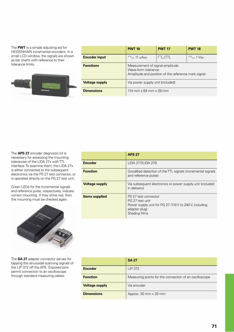
71
SA 27
Encoder LIP 372
Function Measuring points for the connection of an oscilloscope
Voltage supply Via encoder
Dimensions Approx. 30 mm x 30 mm
The SA 27 adapter connector serves for tapping the sinusoidal scanning signals of the LIP 372 off the APE. Exposed pins permit connection to an oscilloscope through standard measuring cables.
The PWT is a simple adjusting aid for HEIDENHAIN incremental encoders. In a small LCD window, the signals are shown as bar charts with reference to their tolerance limits.
PWT 10 PWT 17 PWT 18
Encoder input » 11 µAPP « TTL » 1 VPP
Functions Measurement of signal amplitudeWave-form toleranceAmplitude and position of the reference mark signal
Voltage supply Via power supply unit (included)
Dimensions 114 mm x 64 mm x 29 mm
The APS 27 encoder diagnostic kit is necessary for assessing the mounting tolerances of the LIDA 27x with TTL interface. To examine them, the LIDA 27x is either connected to the subsequent electronics via the PS 27 test connector, or is operated directly on the PG 27 test unit.
Green LEDs for the incremental signals and reference pulse, respectively, indicate correct mounting. If they shine red, then the mounting must be checked again.
APS 27
Encoder LIDA 277/LIDA 279
Function Good/bad detection of the TTL signals (incremental signals and reference pulse)
Voltage supply Via subsequent electronics or power supply unit (included in delivery)
Items supplied PS 27 test connectorPG 27 test unitPower supply unit for PG 27 (110 V to 240 V, including adapter plug)Shading fi lms
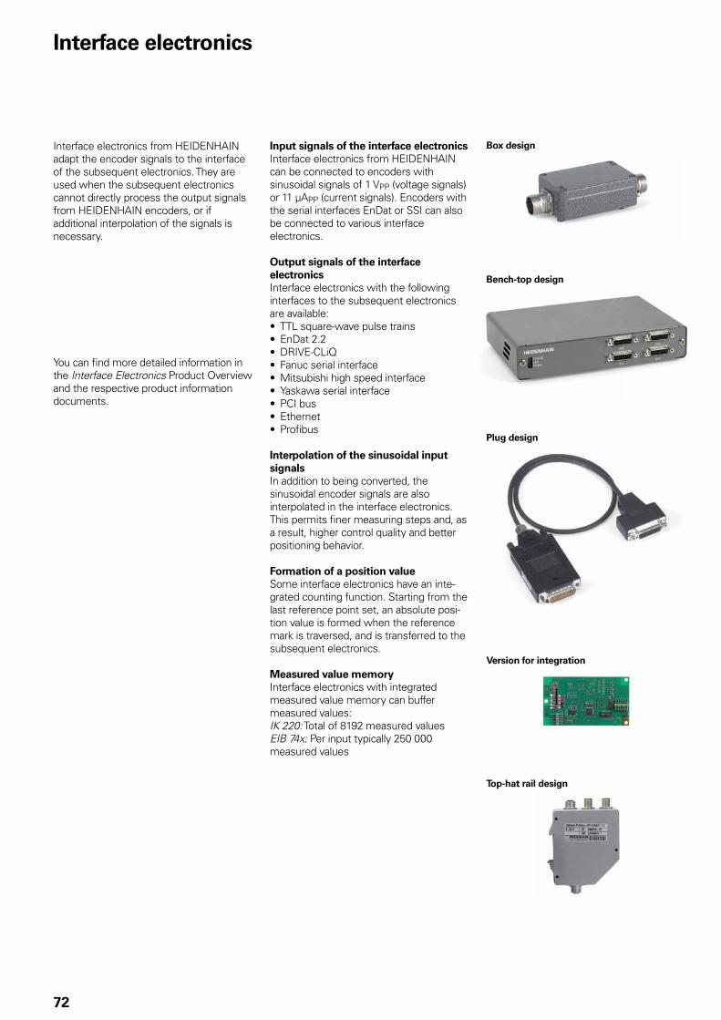
72
Interface electronics
Interface electronics from HEIDENHAIN adapt the encoder signals to the interface of the subsequent electronics. They are used when the subsequent electronics cannot directly process the output signals from HEIDENHAIN encoders, or if additional interpolation of the signals is necessary.
Input signals of the interface electronicsInterface electronics from HEIDENHAIN can be connected to encoders with sinusoidal signals of 1 VPP (voltage signals) or 11 µAPP (current signals). Encoders with the serial interfaces EnDat or SSI can also be connected to various interface electronics.
Output signals of the interface electronicsInterface electronics with the following interfaces to the subsequent electronics are available:• TTL square-wave pulse trains• EnDat 2.2• DRIVE-CLiQ• Fanuc serial interface• Mitsubishi high speed interface• Yaskawa serial interface• PCI bus• Ethernet• Profi bus
Interpolation of the sinusoidal input signalsIn addition to being converted, the sinusoidal encoder signals are also interpolated in the interface electronics. This permits fi ner measuring steps and, as a result, higher control quality and better positioning behavior.
Formation of a position valueSome interface electronics have an inte-grated counting function. Starting from the last reference point set, an absolute posi-tion value is formed when the reference mark is traversed, and is transferred to the subsequent electronics.
Measured value memoryInterface electronics with integrated measured value memory can buffer measured values:IK 220: Total of 8192 measured valuesEIB 74x: Per input typically 250 000 measured values
You can fi nd more detailed information in the Interface Electronics Product Overview and the respective product information documents.
Box design
Plug design
Version for integration
Bench-top design
Top-hat rail design
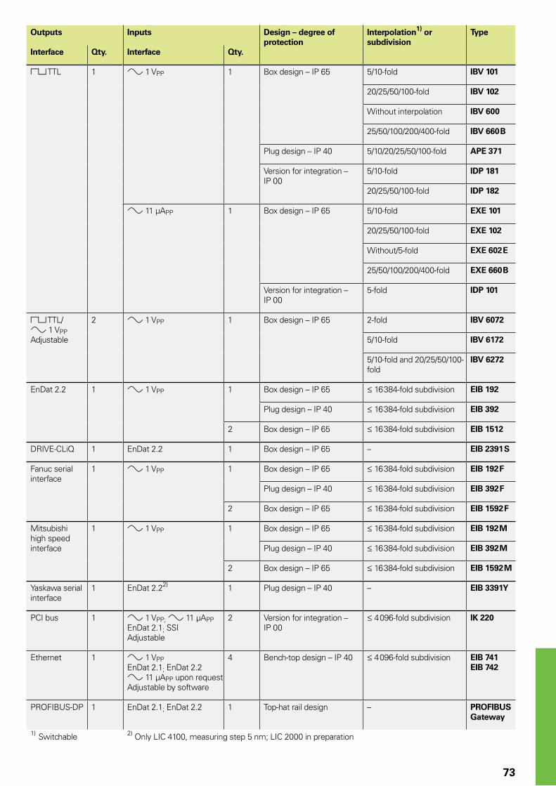
73
Outputs Inputs Design – degree of protection
Interpolation1) or subdivision
Type
Interface Qty. Interface Qty.
« TTL 1 » 1 VPP 1 Box design – IP 65 5/10-fold IBV 101
20/25/50/100-fold IBV 102
Without interpolation IBV 600
25/50/100/200/400-fold IBV 660 B
Plug design – IP 40 5/10/20/25/50/100-fold APE 371
Version for integration – IP 00
5/10-fold IDP 181
20/25/50/100-fold IDP 182
» 11 µAPP 1 Box design – IP 65 5/10-fold EXE 101
20/25/50/100-fold EXE 102
Without/5-fold EXE 602 E
25/50/100/200/400-fold EXE 660 B
Version for integration – IP 00
5-fold IDP 101
« TTL/ » 1 VPPAdjustable
2 » 1 VPP 1 Box design – IP 65 2-fold IBV 6072
5/10-fold IBV 6172
5/10-fold and 20/25/50/100-fold
IBV 6272
EnDat 2.2 1 » 1 VPP 1 Box design – IP 65 16 384-fold subdivision EIB 192
Plug design – IP 40 16 384-fold subdivision EIB 392
2 Box design – IP 65 16 384-fold subdivision EIB 1512
DRIVE-CLiQ 1 EnDat 2.2 1 Box design – IP 65 – EIB 2391 S
Fanuc serial interface
1 » 1 VPP 1 Box design – IP 65 16 384-fold subdivision EIB 192 F
Plug design – IP 40 16 384-fold subdivision EIB 392 F
2 Box design – IP 65 16 384-fold subdivision EIB 1592 F
Mitsubishi high speed interface
1 » 1 VPP 1 Box design – IP 65 16 384-fold subdivision EIB 192 M
Plug design – IP 40 16 384-fold subdivision EIB 392 M
2 Box design – IP 65 16 384-fold subdivision EIB 1592 M
Yaskawa serial interface
1 EnDat 2.22) 1 Plug design – IP 40 – EIB 3391 Y
PCI bus 1 » 1 VPP; » 11 µAPPEnDat 2.1; SSIAdjustable
2 Version for integration – IP 00
4 096-fold subdivision IK 220
Ethernet 1 » 1 VPPEnDat 2.1; EnDat 2.2» 11 µAPP upon requestAdjustable by software
4 Bench-top design – IP 40 4 096-fold subdivision EIB 741EIB 742
PROFIBUS-DP 1 EnDat 2.1; EnDat 2.2 1 Top-hat rail design – PROFIBUS Gateway
1) Switchable 2) Only LIC 4100, measuring step 5 nm; LIC 2000 in preparation
PL APS02-384 Warszawa, Poland www.heidenhain.pl
PT FARRESA ELECTRÓNICA, LDA.4470 - 177 Maia, Portugal www.farresa.pt
RO HEIDENHAIN Reprezentanta RomaniaBrasov, 500407, Romania www.heidenhain.ro
RS Serbia BG
RU OOO HEIDENHAIN115172 Moscow, Russia www.heidenhain.ru
SE HEIDENHAIN Scandinavia AB12739 Skärholmen, Sweden www.heidenhain.se
SG HEIDENHAIN PACIFIC PTE LTD.Singapore 408593 www.heidenhain.com.sg
SK KOPRETINA TN s.r.o.91101 Trencin, Slovakia www.kopretina.sk
SL NAVO d.o.o.2000 Maribor, Slovenia www.heidenhain.si
TH HEIDENHAIN (THAILAND) LTDBangkok 10250, Thailand www.heidenhain.co.th
TR T&M Mühendislik San. ve Tic. LTD. STI·.
34728 Ümraniye-Istanbul, Turkey www.heidenhain.com.tr
TW HEIDENHAIN Co., Ltd.Taichung 40768, Taiwan R.O.C. www.heidenhain.com.tw
UA Gertner Service GmbH Büro Kiev 01133 Kiev, Ukraine www.heidenhain.ua
US HEIDENHAIN CORPORATIONSchaumburg, IL 60173-5337, USA www.heidenhain.com
VE Maquinaria Diekmann S.A. Caracas, 1040-A, Venezuela E-mail: [email protected]
VN AMS Co. LtdHCM City, VietnamE-mail: [email protected]
ZA MAFEMA SALES SERVICES C.C.Midrand 1685, South Africa www.heidenhain.co.za
ES FARRESA ELECTRONICA S.A.08028 Barcelona, Spain www.farresa.es
FI HEIDENHAIN Scandinavia AB02770 Espoo, Finland www.heidenhain.fi
FR HEIDENHAIN FRANCE sarl92310 Sèvres, France www.heidenhain.fr
GB HEIDENHAIN (G.B.) LimitedBurgess Hill RH15 9RD, United Kingdom www.heidenhain.co.uk
GR MB Milionis Vassilis17341 Athens, Greece www.heidenhain.gr
HK HEIDENHAIN LTDKowloon, Hong Kong E-mail: [email protected]
HR Croatia SL
HU HEIDENHAIN Kereskedelmi Képviselet1239 Budapest, Hungary www.heidenhain.hu
ID PT Servitama Era ToolsindoJakarta 13930, Indonesia E-mail: [email protected]
IL NEUMO VARGUS MARKETING LTD.Tel Aviv 61570, Israel E-mail: [email protected]
IN HEIDENHAIN Optics & Electronics India Private LimitedChetpet, Chennai 600 031, India www.heidenhain.in
IT HEIDENHAIN ITALIANA S.r.l.20128 Milano, Italy www.heidenhain.it
JP HEIDENHAIN K.K.Tokyo 102-0083, Japan www.heidenhain.co.jp
KR HEIDENHAIN Korea LTD.Gasan-Dong, Seoul, Korea 153-782 www.heidenhain.co.kr
MX HEIDENHAIN CORPORATION MEXICO20235 Aguascalientes, Ags., Mexico E-mail: [email protected]
MY ISOSERVE SDN. BHD.43200 Balakong, Selangor E-mail: [email protected]
NL HEIDENHAIN NEDERLAND B.V.6716 BM Ede, Netherlands www.heidenhain.nl
NO HEIDENHAIN Scandinavia AB7300 Orkanger, Norway www.heidenhain.no
PH Machinebanks` CorporationQuezon City, Philippines 1113 E-mail: [email protected]
AR NAKASE SRL.B1653AOX Villa Ballester, Argentina www.heidenhain.com.ar
AT HEIDENHAIN Techn. Büro Österreich83301 Traunreut, Germany www.heidenhain.de
AU FCR Motion Technology Pty. LtdLaverton North 3026, Australia E-mail: [email protected]
BE HEIDENHAIN NV/SA1760 Roosdaal, Belgium www.heidenhain.be
BG ESD Bulgaria Ltd.Sofia 1172, Bulgaria www.esd.bg
BR DIADUR Indústria e Comércio Ltda.04763-070 – São Paulo – SP, Brazil www.heidenhain.com.br
BY GERTNER Service GmbH220026 Minsk, Belarus www.heidenhain.by
CA HEIDENHAIN CORPORATIONMississauga, OntarioL5T2N2, Canada www.heidenhain.com
CH HEIDENHAIN (SCHWEIZ) AG8603 Schwerzenbach, Switzerland www.heidenhain.ch
CN DR. JOHANNES HEIDENHAIN (CHINA) Co., Ltd.Beijing 101312, China www.heidenhain.com.cn
CZ HEIDENHAIN s.r.o.102 00 Praha 10, Czech Republic www.heidenhain.cz
DK TP TEKNIK A/S2670 Greve, Denmark www.tp-gruppen.dk
DE HEIDENHAIN Vertrieb Deutschland83301 Traunreut, Deutschland 08669 31-3132| 08669 32-3132E-Mail: [email protected]
HEIDENHAIN Technisches Büro Nord12681 Berlin, Deutschland 030 54705-240
HEIDENHAIN Technisches Büro Mitte07751 Jena, Deutschland 03641 4728-250
HEIDENHAIN Technisches Büro West44379 Dortmund, Deutschland 0231 618083-0
HEIDENHAIN Technisches Büro Südwest70771 Leinfelden-Echterdingen, Deutschland 0711 993395-0
HEIDENHAIN Technisches Büro Südost83301 Traunreut, Deutschland 08669 31-1345
Vollständige und weitere Adressen siehe www.heidenhain.de For complete and further addresses see www.heidenhain.de
Zu
m A
bh
efte
n h
ier
falz
en!
/ Fo
ld h
ere
for
filin
g!
������������������������������������������������������������������������������������� �������������� ���������������������������������������
�����������������
*I_208960-2B*
208960-2B · 15 · 5/2014 · H · Printed in Germany