Embed Size (px)
Citation preview
Booklet ofInstallation Instructions
for SAW Sensors
Document No. 466-1622
Revision D, January 2000
Installation instructions for the SAW sensors listed in the following table are included in this document. The SAW sensor installation instructions in this booklet are to be used with the panel installation in-structions for the Simon® Panel. These instructions will not be packaged with the sensor hardware.
Table of Contents
Sensor Description Document Number
60-639-95R60-639-95R-OD
Indoor and Outdoor PIR Motion Sensors
466-1534 (Rev. B)
60-659-95R KeyChain Touchpad 466-1560 (Rev. A)
60-670-95R Door/Window Sensor 466-1559 (Rev. A)
60-671-95R Remote Handheld Touchpad 466-1561 (Rev. A)
60-742 Freeze Sensor 466-1541 (Rev. C)
60-744 Water Sensor 466-1539 (Rev. C)
60-788 Touchtalk 2-Way RF Touchpad 466-1595 (Rev. C)
1

2
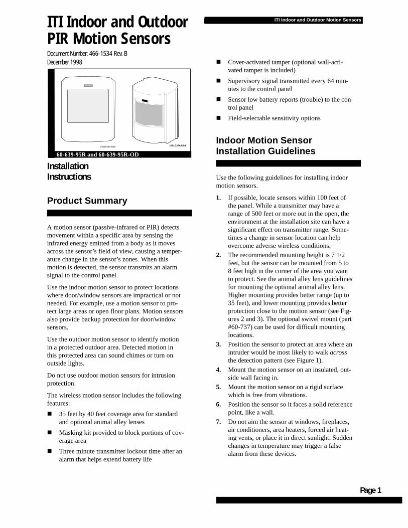
ITI Indoor and Outdoor Motion Sensors
ITI Indoor and Outdoor PIR Motion SensorsDocument Number: 466-1534 Rev. BDecember 1998
InstallationInstructions
Product Summary
A motion sensor (passive-infrared or PIR) detects movement within a specific area by sensing the infrared energy emitted from a body as it moves across the sensor’s field of view, causing a temper-ature change in the sensor’s zones. When this motion is detected, the sensor transmits an alarm signal to the control panel.
Use the indoor motion sensor to protect locations where door/window sensors are impractical or not needed. For example, use a motion sensor to pro-tect large areas or open floor plans. Motion sensorsalso provide backup protection for door/window sensors.
Use the outdoor motion sensor to identify motion in a protected outdoor area. Detected motion in this protected area can sound chimes or turn on outside lights.
Do not use outdoor motion sensors for intrusion protection.
The wireless motion sensor includes the following features:
� 35 feet by 40 feet coverage area for standard and optional animal alley lenses
� Masking kit provided to block portions of cov-erage area
� Three minute transmitter lockout time after an alarm that helps extend battery life
8362G12A.DS4
60-639-95R and 60-639-95R-OD
1061G37A.DS4
� Cover-activated tamper (optional wall-acti-vated tamper is included)
� Supervisory signal transmitted every 64 min-utes to the control panel
� Sensor low battery reports (trouble) to the con-trol panel
� Field-selectable sensitivity options
Indoor Motion Sensor Installation Guidelines
Use the following guidelines for installing indoor motion sensors.
1. If possible, locate sensors within 100 feet of the panel. While a transmitter may have a range of 500 feet or more out in the open, the environment at the installation site can have a significant effect on transmitter range. Some-times a change in sensor location can help overcome adverse wireless conditions.
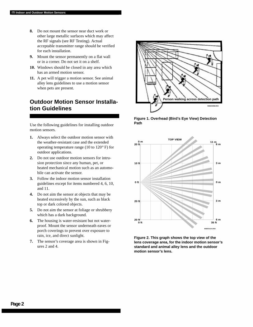
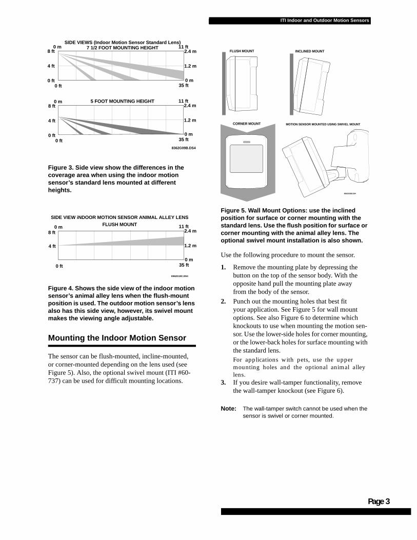
2. The recommended mounting height is 7 1/2 feet, but the sensor can be mounted from 5 to 8 feet high in the corner of the area you want to protect. See the animal alley lens guidelines for mounting the optional animal alley lens. Higher mounting provides better range (up to 35 feet), and lower mounting provides better protection close to the motion sensor (see Fig-ures 2 and 3). The optional swivel mount (part #60-737) can be used for difficult mounting locations.
3. Position the sensor to protect an area where anintruder would be most likely to walk across the detection pattern (see Figure 1).
4. Mount the motion sensor on an insulated, out-side wall facing in.
5. Mount the motion sensor on a rigid surface which is free from vibrations.
6. Position the sensor so it faces a solid referencepoint, like a wall.
7. Do not aim the sensor at windows, fireplaces, air conditioners, area heaters, forced air heat-ing vents, or place it in direct sunlight. Sudden changes in temperature may trigger a false alarm from these devices.
Page 1
Page 2
ITI Indoor and Outdoor Motion Sensors
8. Do not mount the sensor near duct work or other large metallic surfaces which may affect the RF signals (see RF Testing). Actual acceptable transmitter range should be verified for each installation.
9. Mount the sensor permanently on a flat wall or in a corner. Do not set it on a shelf.
10. Windows should be closed in any area which has an armed motion sensor.
11. A pet will trigger a motion sensor. See animal alley lens guidelines to use a motion sensor when pets are present.
Outdoor Motion Sensor Installa-tion Guidelines
Use the following guidelines for installing outdoor motion sensors.
1. Always select the outdoor motion sensor with the weather-resistant case and the extended operating temperature range (10 to 120° F) for outdoor applications.
2. Do not use outdoor motion sensors for intru-sion protection since any human, pet, or heated mechanical motion such as an automo-bile can activate the sensor.
3. Follow the indoor motion sensor installation guidelines except for items numbered 4, 6, 10, and 11.
4. Do not aim the sensor at objects that may be heated excessively by the sun, such as black top or dark colored objects.
5. Do not aim the sensor at foliage or shrubbery which has a dark background.
6. The housing is water-resistant but not water-proof. Mount the sensor underneath eaves or porch coverings to prevent over exposure to rain, ice, and direct sunlight.
7. The sensor’s coverage area is shown in Fig-ures 2 and 4.
Figure 1. Overhead (Bird’s Eye View) Detection Path
Figure 2. This graph shows the top view of the lens coverage area, for the indoor motion sensor’s standard and animal alley lens and the outdoor motion sensor’s lens.
8362G04B.DS4
Person walking across detection path
8362G11A.DS4
0 ft20 ft
20 ft
0 ft
10 ft
20 ft0 m 11 m
TOP VIEW
6 m
3 m
0 m
3 m
6 m
35 ft
ITI Indoor and Outdoor Motion Sensors
-g, h
Figure 3. Side view show the differences in the coverage area when using the indoor motion sensor’s standard lens mounted at different heights.
Figure 4. Shows the side view of the indoor motion sensor’s animal alley lens when the flush-mount position is used. The outdoor motion sensor’s lens also has this side view, however, its swivel mount makes the viewing angle adjustable.
Mounting the Indoor Motion Sensor
The sensor can be flush-mounted, incline-mounted, or corner-mounted depending on the lens used (see Figure 5). Also, the optional swivel mount (ITI #60-737) can be used for difficult mounting locations.
Figure 5. Wall Mount Options: use the inclined position for surface or corner mounting with the standard lens. Use the flush position for surface or corner mounting with the animal alley lens. The optional swivel mount installation is also shown.
Use the following procedure to mount the sensor.
1. Remove the mounting plate by depressing the button on the top of the sensor body. With the opposite hand pull the mounting plate away from the body of the sensor.
2. Punch out the mounting holes that best fit your application. See Figure 5 for wall mount options. See also Figure 6 to determine which knockouts to use when mounting the motion sensor. Use the lower-side holes for corner mountinor the lower-back holes for surface mounting witthe standard lens.For applications with pets, use the upper mounting holes and the optional animal alley lens.
3. If you desire wall-tamper functionality, remove the wall-tamper knockout (see Figure 6).
Note: The wall-tamper switch cannot be used when the sensor is swivel or corner mounted.
8362G10C.DS4
8 ft0 m
4 ft
0 ft 35 ft
11 ft2.4 m
1.2 m
0 m
SIDE VIEW iNDOOR MOTION SENSOR ANIMAL ALLEY LENS
FLUSH MOUNT
8362G03B.DS4
FLUSH MOUNT INCLINED MOUNT
CORNER MOUNT MOTION SENSOR MOUNTED USING SWIVEL MOUNT
8362G09B.DS4
8 ft0 m
4 ft
0 ft35 ft
11 ft2.4 m
1.2 m
0 m
SIDE VIEWS (Indoor Motion Sensor Standard Lens)7 1/2 FOOT MOUNTING HEIGHT
0 ft
8 ft0 m
4 ft
0 ft0 ft 35 ft
11 ft2.4 m
1.2 m
0 m
5 FOOT MOUNTING HEIGHT
Page 3
Page 4
ITI Indoor and Outdoor Motion Sensors
Figure 6. PIR Mounting Plate Knockouts
4. Mark the location of the required holes on the mounting surface.
5. Use wall anchors and screws to secure into place. Attach the sensor to the mounting plate.
6. When testing is completed the PIR can be securely attached to its mounting plate by screwing the smallest enclosed screw into the hole at the top of the mounting plate.
Mounting the Outdoor Motion Sensor
1. Determine the desired mounting location for the sensor leaving at least four inches of room above the wall mount plate to attach the sen-sor.
2. Attach the wall mount plate with the opening for the swivel mount facing downward using the screws and anchors supplied.
3. Attach the sensor assembly to the wall mount plate by screwing the sensor assembly up into the opening in the wall mount plate.
4. To remove the sensor for testing or battery replacement, slide the front cover of the sen-sor upward until the sensor can be removed.
Indoor Motion Sensor Lens Replacement:
1. To change the lens, first remove the sensor from its mounting plate by depressing the but-ton on the top of the sensor.
2. Remove the cover by depressing the two tabs on the top and the one tab on the bottom of the sensor body and sliding the cover off (see Figure 8).
3. Remove the installed lens by gently placing pressure on the lens from the outside of the lens.
4. Replace with the appropriate lens by aligning its notches with the appropriate tabs in the cover.
5. Install the new lens with the smooth side fac-ing out and the grooved side facing in.
6. Replace the cover and then replace the sensor in its mounting plate.
Indoor Motion Sensor Animal Alley Lens Guidelines
The optional animal alley lens (part #60-709) pro-vides protection in installations where pets move about freely. See figures 2 and 4 for coverage.
� Allowed mounting height is between 3 and 5 feet.
� Be sure to use the flush-mount position or the corner mount position with the back of the PIR parallel to the walls. Do not use the inclined mount position since this would tilt the PIR’s field of view downward.
� Position the sensor to have a clear line of sight across the protected room.
� For best results, install the sensor higher than the highest point that the pet might reach in the detection area.
� If the detection area contains furniture or other objects upon which the pet could climb or jump, either remove these objects, mount the PIR a safe distance above these objects, or mask these areas.
USE WITHSTANDARD LENS
USE WITHANIMAL ALLEY LENS
8362G01B.DS4
WALL TAMPER
KNOCKOUT
ge 5
ITI Indoor and Outdoor Motion Sensors
Pa
Setting the Sensitivity on the Indoor Motion Sensor
The PIR is set to standard sensitivity at the fac-tory. This sensitivity is preferred for most applica-tions and provides the best immunity to false alarms.
CAUTION: High sensitivity should only be used in extremely quiet environments where thermal transients are not expected.
1. Locate the sensitivity pins by first removing the mounting plate and the sensor cover as described in steps 1 and 2 of Lens Replace-ment process.
Figure 7. Sensitivity Pins Locations
2. Locate the sensitivity pins under the battery on the right side of the PIR when looking at the front of the PIR.
3. To change to high sensitivity move the short-ing jumper to the pair of pins that are closer to the top of the PIR (see Figure 7).
Note: If the shorting jumper is not used or placed incor-rectly, the sensor defaults to standard sensitivity.
4. Walk test the PIR to verify the sensitivity.
Walk Testing the Indoor and Outdoor Motion Sensors
Walk testing should be done to determine the sen-sor’s actual coverage area. The edge of the cover-age pattern is determined by the first flash of the LED. This may change slightly depending upon the sensitivity setting. Walk test the unit from both directions to determine the pattern boundaries.
1. Remove the sensor body from the mounted mounting plate, activate the tamper switch, andthen remount the body to activate the 60 sec-ond walk test mode.
2. Walk across the coverage pattern to determine the coverage area, indicated by LED activa-tion. Each activation extends the walk test mode for an additional 60 seconds.
After 60 seconds without motion the walk test mode and the LED will no longer activate when motion is detected.
Note: Excessive use of the walk test mode may reduce battery life. Use only for initial setup and mainte-nance testing.
Note: When the walk test mode has ended, an alarm can be transmitted only after 3 minutes have passed since the previous alarm. This 3 minute lockout time reduces unnecessary RF transmis-sions in high traffic areas thereby extending bat-tery life.
Environment Testing
Indoor Motion Sensors:
Turn on all heating or air conditioning sources which would normally be active during the protec-tion period. Stand away from the sensor and out-side the coverage pattern and watch for alarms.
Outdoor Motion Sensors:
Verify that the sensor’s coverage area doe not extend into undesired areas that might cause unwanted activations. These areas may include undesired human, pet, or automobile motion.
8362G06A.DS4
STANDARD
HIGH
Page 6
ITI Indoor and Outdoor Motion Sensors
Coverage Masking
After walk testing and environment testing are completed, masking labels can be applied to the sensor’s lens to block detection of problem areas. The masking labels provided are cut to match the corresponding lens segments.
1. Determine which detection zone/lens segment needs a masking label.
2. Peel the desired mask label from its backing and apply to the inside of the lens segment to be blocked.
Outdoor Motion Sensor Filter Installa-tion:
A 1 inch by 1 inch piece of lens material has been included with the outdoor motion sensor. This filter reduces the sensors sensitivity to white light sources (sunlight and head lights) and infrared sources. Install this filter when experiencing unwanted sensor activations due to these sources.
1. Remove the sensor from its water resistant enclosure by sliding the front cover upward until the sensor can be removed.
2. Remove the mounting plate of the sensor by depressing the button on top of the sensor.
3. Remove the front cover of the sensor by depressing the two tabs on the top and the one tab on the bottom of the sensor body and sliding the cover off (see figure 8)
4. Place the sensor on its back and drop the fil-ter into the lens chamber covering the sensor’s detector.
5. Replace the cover making sure the filter remains in the lens chamber and does not interfere with the attachment of the cover.
6. Replace the sensor’s mounting plate and install the sensor in its water resistant enclosure.
Programming
Follow these instructions to program the sensor:1. Open the Control Panel.2. Enter Utility Access Code 1 or 2 using the
red-numbered buttons.3. Press Add from the Start Menu.4. Press the Sensor/Remote button from the Main
menu until you hear the location you wish to use with the sensor.
The order of names the Control Panel uses are: keychain remote, touchpad remote, front door, back door, garage door, bedroom, guest room, child’s room, utility room, living room, dining room, bathroom, laundry room, kitchen, office, den, garage, special chime, basement, upstairs, downstairs, hallway, medicine cabinet,closet, attic. Each name may be used more than once.
Note: When adding sensors, if you wish to use a more descriptive location you may press the option button to use the compass directions (north, north east, east, south east, south, south west, west, north west).
5. Press DONE.6. Enter the sensor type number (17 (intrusion),
25 (chime)) with the red numbered keys.
Note: If you wish to use a sensor number other than the next available, enter a 2 digit sensor number with the red numbered keys immediately after entering the sensor type.
7. Trip the PIR by removing the PIR from its mounting plate and activating the tamper switch.
8. Exit the program mode after all appropriate assignments have been made.
9. Return the PIR to its mounting plate.
ITI Indoor and Outdoor Motion Sensors
Maintenance
At least once a year, the range and coverage should be verified for proper operation. The end user should be instructed to put the sensor in walk test mode and walk through the far end of the cov-erage pattern to verify proper detection.
Replacing Batteries
When battery replacement is necessary, observe proper polarity (as shown in the battery compart-ment) when installing the new battery, or the sen-sor may be damaged. Be sure to note that as you look at the battery compartment, on the left side the positive side is down and on the right side the positive end is up. When the battery is replaced, wait at least 3 minutes after installing the battery before activating the walk test mode. See Figure 8 for battery locations.
Figure 8. PIR Components, Battery Locations, & Tamper Switch
Final Testing
Final testing should be done to verify radio signal integrity and confirm control panel programming and response. The actual transmitter range can be determined by performing a sensor test as follows:
1. After the sensor has been mounted, remove it from its mounting plate and activate the tamper switch to start the walk test mode.
2. Replace the sensor in its mounting plate.
3. Place the control panel in test mode. Move across the detection pattern until the sensor’s LED turns on. STOP your motion.
4. Listen for the appropriate system response. If the system does not respond, proceed to the “Troubleshooting “section.
Troubleshooting
Use the following guidelines if the system does not respond correctly when the sensor is activated.
� Check programming and re-program sensor into panel if necessary.
� Move the sensor to another location and test for correct response.
To relocate a sensor:
1. Test the sensor a few inches from the original position.
2. Increase the distance from the original position and retest until an acceptable location is found.
3. Mount the sensor in the new location.
4. If no location is acceptable, test the sensor as described below:
1. Test a known good sensor at the same location.
2. If the system does not respond, avoid mounting a sensor at that location.
3. If the replacement sensor functions, return the problem sensor for repair or replace-ment.
8362G02A.DS4MOUNTINGPLATE
SENSORBODY
PIR COVER
LENS
TAMPERSWITCH
PWBCOVER
TABS
Page 7
Page 8
ITI Indoor and Outdoor Motion Sensors
Specifications
Power source: 2 AA alkaline batteries
Typical battery life: 2-4 years at 68° F (not veri-fied by U.L.)
Operating temperature range:
32° to 120° F (Indoor Motion Sensor)
10° to 120° F (Outdoor Motion Sensor)
Dimensions: L = 2.875” X W = 2.375” X H = 1.875”
Notices
These devices comply with part 15 of the FCC rules. Operation issubject to the following two conditions:
1. These devices may not cause harmful interference.
2. These devices must accept any interference received, includinginterference that may cause undesired operation.
Changes or modifications not expressly approved by InteractiveTechnologies, Inc. can void the users’ authority to operate theequipment.
6 5 1 - 7 7 7 - 2 6 9 0
6 5 1 - 7 7 9 - 4 8 9 0
SAW KeyChain Touchpad
Page 1
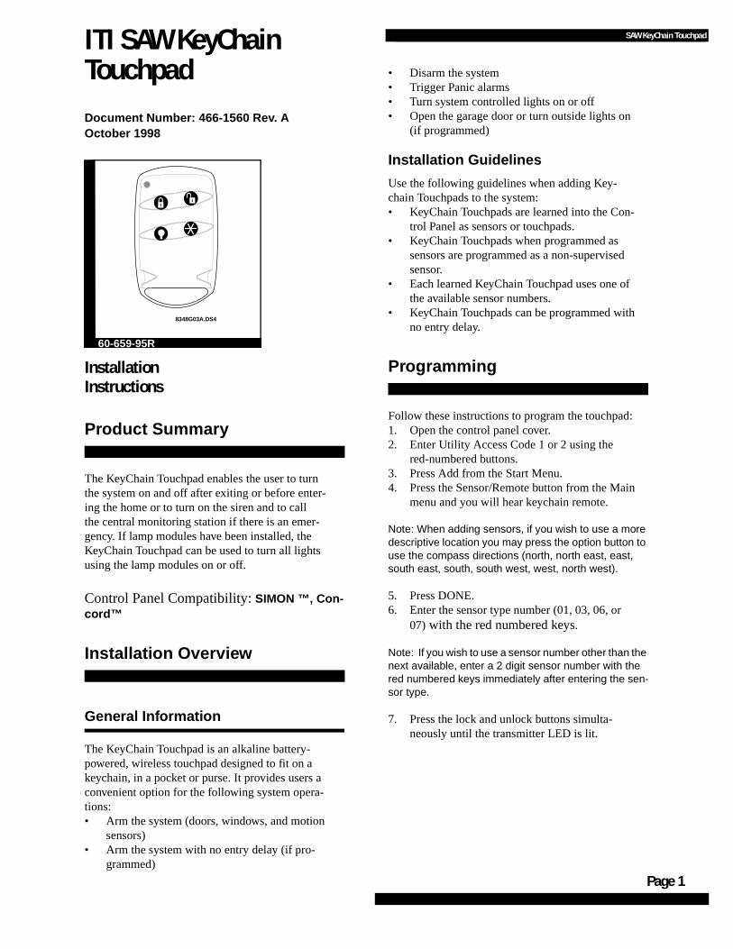
ITI SAW KeyChain Touchpad
Document Number: 466-1560 Rev. AOctober 1998
Installation Instructions
Product Summary
The KeyChain Touchpad enables the user to turn the system on and off after exiting or before enter-ing the home or to turn on the siren and to call the central monitoring station if there is an emer-gency. If lamp modules have been installed, the KeyChain Touchpad can be used to turn all lights using the lamp modules on or off.
Control Panel Compatibility: SIMON ™, Con-cord™
Installation Overview
General Information
The KeyChain Touchpad is an alkaline battery-powered, wireless touchpad designed to fit on a keychain, in a pocket or purse. It provides users a convenient option for the following system opera-tions:• Arm the system (doors, windows, and motion
sensors)• Arm the system with no entry delay (if pro-
grammed)
8348G03A.DS4
60-659-95R
• Disarm the system • Trigger Panic alarms• Turn system controlled lights on or off• Open the garage door or turn outside lights on
(if programmed)
Installation Guidelines
Use the following guidelines when adding Key-chain Touchpads to the system:• KeyChain Touchpads are learned into the Con-
trol Panel as sensors or touchpads.• KeyChain Touchpads when programmed as
sensors are programmed as a non-supervised sensor.
• Each learned KeyChain Touchpad uses one of the available sensor numbers.
• KeyChain Touchpads can be programmed with no entry delay.
Programming
Follow these instructions to program the touchpad:1. Open the control panel cover.2. Enter Utility Access Code 1 or 2 using the
red-numbered buttons.3. Press Add from the Start Menu.4. Press the Sensor/Remote button from the Main
menu and you will hear keychain remote.
Note: When adding sensors, if you wish to use a more descriptive location you may press the option button to use the compass directions (north, north east, east, south east, south, south west, west, north west).
5. Press DONE.6. Enter the sensor type number (01, 03, 06, or
07) with the red numbered keys.
Note: If you wish to use a sensor number other than the next available, enter a 2 digit sensor number with the red numbered keys immediately after entering the sen-sor type.
7. Press the lock and unlock buttons simulta-neously until the transmitter LED is lit.
Page
SAW KeyChain Touchpad
Testing KeyChain Touchpads Used with the SIMON ™ Control Panel
Perform Sensor Test
The following steps describe the guidelines for test-ing sensors.
1. Open the Control Panel cover. 2. Enter the Utility Access Code 1 or 2 using the
red-numbered buttons.3. Press the Test button once.4. Press DONE.5. Trip the sensor by pressing the Lock and
Unlock buttons simultaneously until the LED is lit.
6. Note the number of siren beeps indicating how many RF packets the Control Panel received from the sensor. You should hear 7-8 beeps.
Test the KeyChain Touchpad by pressing the but-tons as described below:1. Disarm or Unlock Button -The Control Panel
is disarmed. Doors, Windows, and Motion Sensors are disarmed.
2. Lock Button - The Control Panel may be pro-grammed with no delay from KeyChain on or off. The following keypresses will be depen-dent on programming option 28.
• if pressed once, the Control Panel arms doors and windows.
• if pressed twice, the Control Panel arms motion sensors.
• if pressed three times, the Control Panel acti-vates the latchkey feature when this option is off.
3. Light Button toggles system controlled lights on/off.
4. Star Button - If used with the X-10 Universal Module, the Control Panel will cause the garage door to open or close.
5. Lock and Unlock Buttons - If learned in as sensor type: Intrusion, Silent Alarm, or Emer-gency, when pressed simultaneously, will acti-vate alarm reports to the central station. These 2 buttons are also used to test the sensor.
Specifications
Power Source: 12 V 33 mAh alkaline battery
Typical battery life: 5 - 8 years
Operating temperature range: 10° to 120° F
Dimensions: L = 2.30” x W = 1.45” x H =.48”
FCC NOTICE
This device complies with FCC Rules Part 15. operation is subject to the following two
conditions:
1) This may not cause harmful interference.
2) This device must accept any interference that may be received, including interfer-
ence that may cause undesired operation.
Changes or modifications not expressly approved by Interactive Technologies, Inc. can
void the user’s authority to operate the equipment.
6 5 1 - 7 7 7 - 2 6 9 0
6 5 1 - 7 7 9 - 4 8 9 0
2

SAW Door/Window Sensors
Page 1
.
ITI SAW Door/Window Sensor
Document Number: 466-1559 Rev. AOctober 1998
InstallationInstructions
Product Summary
General Information
Door/Window Sensors can be installed on doors, windows, or many other objects that open and closeThe sensors transmit signals to the Control Panel when a magnet mounted near the sensor is moved away from or closer to the sensor.
Control Panel Compatibility: SIMON ™
Installation Guidelines
Use the following guidelines for installing Door/Window sensors.
• Mount the sensor on the door frame and the magnet on the door. If the sensor is to be used on double doors, mount the sensor on the least-used door and the magnet on the other door.
• If possible, locate sensors within 100 feet of the panel. While a transmitter may have a range of 500 feet or more out in the open, the environment at the installation site can have a significant effect on transmitter range. Some-times a change in sensor location can help overcome adverse wireless conditions.
60-670-95R
• Make sure the alignment arrow on the magnet points to the alignment mark on the sensor.
• Place sensors at least 5 inches above the floor to avoid damaging them.
• Avoid mounting sensors in areas where they will be exposed to moisture or where the oper-ating temperature (10°-120°F) will be exceeded.
• Use spacers (not included) to keep sensors andmagnets away from metal or metallic surfaces such as foil wallpaper.
Materials Needed• #6 flathead screws• Screwdriver or brad driver
The following illustrations and procedure describe how to install the Door/Window sensor.
Figure 1. Sensor and Magnet Positions
Figure 2. Aligning the Door/Window Sensor and Magnet
Sensor
Magnet
Align Arrowand Mark
Doorframe
2 - AAA Batteries
8959G16B.DS4
Page
SAW Door/Window Sensors
:
,
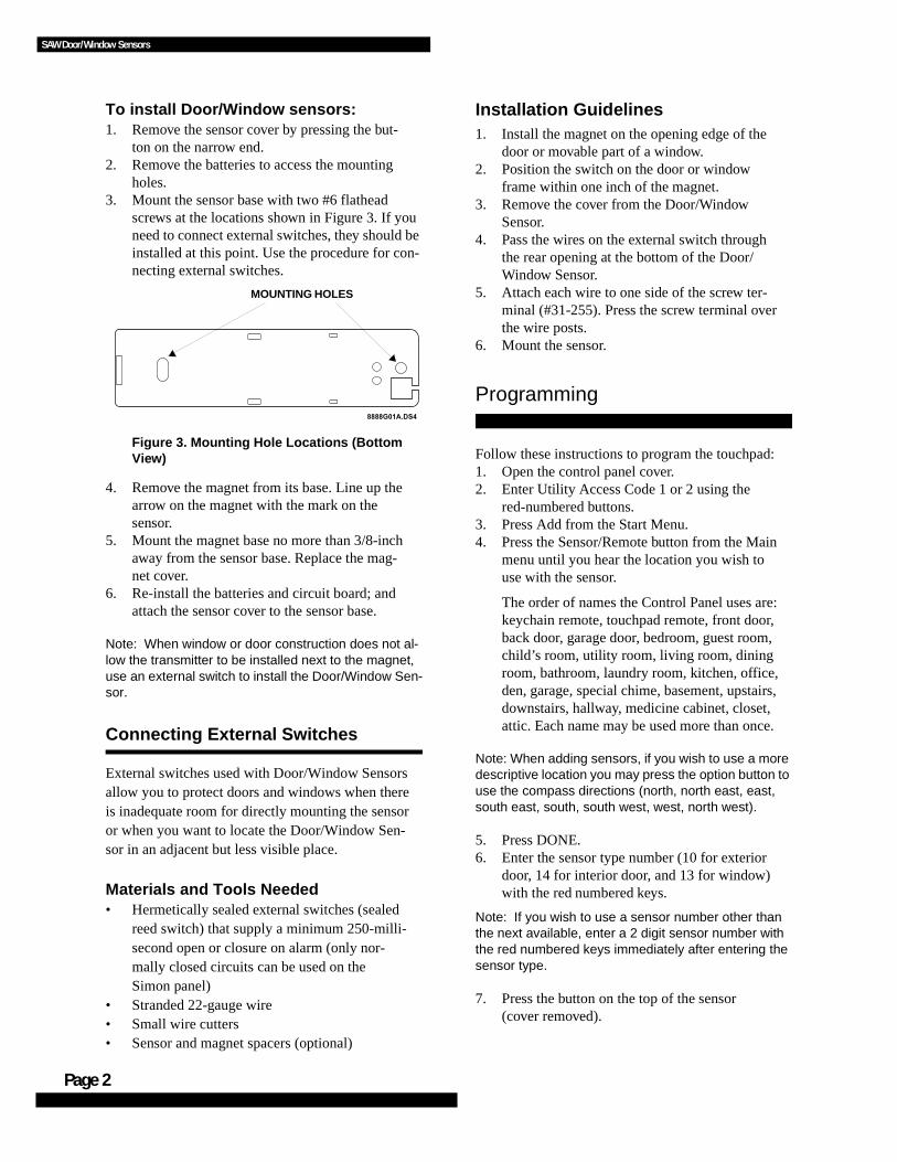
To install Door/Window sensors:1. Remove the sensor cover by pressing the but-
ton on the narrow end.2. Remove the batteries to access the mounting
holes.3. Mount the sensor base with two #6 flathead
screws at the locations shown in Figure 3. If you need to connect external switches, they should be installed at this point. Use the procedure for con-necting external switches.
Figure 3. Mounting Hole Locations (Bottom View)
4. Remove the magnet from its base. Line up the arrow on the magnet with the mark on the sensor.
5. Mount the magnet base no more than 3/8-inch away from the sensor base. Replace the mag-net cover.
6. Re-install the batteries and circuit board; and attach the sensor cover to the sensor base.
Note: When window or door construction does not al-low the transmitter to be installed next to the magnet, use an external switch to install the Door/Window Sen-sor.
Connecting External Switches
External switches used with Door/Window Sensors allow you to protect doors and windows when there is inadequate room for directly mounting the sensor or when you want to locate the Door/Window Sen-sor in an adjacent but less visible place.
Materials and Tools Needed• Hermetically sealed external switches (sealed
reed switch) that supply a minimum 250-milli-second open or closure on alarm (only nor-mally closed circuits can be used on the Simon panel)
• Stranded 22-gauge wire• Small wire cutters• Sensor and magnet spacers (optional)
Installation Guidelines1. Install the magnet on the opening edge of the
door or movable part of a window.2. Position the switch on the door or window
frame within one inch of the magnet.3. Remove the cover from the Door/Window
Sensor.4. Pass the wires on the external switch through
the rear opening at the bottom of the Door/Window Sensor.
5. Attach each wire to one side of the screw ter-minal (#31-255). Press the screw terminal over the wire posts.
6. Mount the sensor.
Programming
Follow these instructions to program the touchpad:1. Open the control panel cover.2. Enter Utility Access Code 1 or 2 using the
red-numbered buttons.3. Press Add from the Start Menu.4. Press the Sensor/Remote button from the Main
menu until you hear the location you wish to use with the sensor.
The order of names the Control Panel uses arekeychain remote, touchpad remote, front door, back door, garage door, bedroom, guest room, child’s room, utility room, living room, dining room, bathroom, laundry room, kitchen, office, den, garage, special chime, basement, upstairsdownstairs, hallway, medicine cabinet, closet, attic. Each name may be used more than once.
Note: When adding sensors, if you wish to use a more descriptive location you may press the option button to use the compass directions (north, north east, east, south east, south, south west, west, north west).
5. Press DONE.6. Enter the sensor type number (10 for exterior
door, 14 for interior door, and 13 for window) with the red numbered keys.
Note: If you wish to use a sensor number other than the next available, enter a 2 digit sensor number with the red numbered keys immediately after entering the sensor type.
7. Press the button on the top of the sensor (cover removed).
8888G01A.DS4
MOUNTING HOLES
2

SAW Door/Window Sensors
Testing Door/Window Sensors used with the Simon Control Panel
The following steps describe the guidelines for test-ing sensors.
1. Open the Control Panel cover. 2. Enter the Utility Access Code 1 or 2 using the
red-numbered buttons.3. Press the Test button once.4. Press DONE.5. Trip the sensor (move the magnet away from
the sensor) and do not replace the magnet until the Control Panel indicates the number of RF packets received.
6. Note the number of siren beeps indicating how many RF packets the Control Panel received from the sensor. You should hear 7-8 beeps.
We recommend that you test the sensors after all programming is completed and whenever a sensor-related problem occurs.
Note: While the sensor test is a valuable installation and service tool, it only tests sensor operation for the current conditions. You should perform a sensor test after any change in environment, equipment, or programming.
If a Sensor Fails the Sensor Test
If sirens do not beep when a sensor is tripped, use an ITI RF Sniffer (60-401) test tool to verify that the sensor is transmitting. Constant beeps from the RF Sniffer indicate a runaway (faulty) sensor. Re-place the sensor.
To improve sensor communication, you can:• reposition the sensor• relocate the sensor• if necessary, replace the sensor
To reposition a sensor:1. Rotate the sensor and test for improved sensor
communication at 90 and 180 degrees from the original position.
2. If poor communication persists, relocate the sensor as described as follows.
To relocate a sensor:1. Test the sensor a few inches from the original
position.2. Increase the distance from the original position
and retest until an acceptable location is found.3. Mount the sensor in the new location.4. If no location is acceptable, replace the sensor.
To replace a sensor:1. Test a known good sensor at the same loca-
tion.2. If the transmission beeps remain below the
minimum level, avoid mounting a sensor at that location.
3. If the replacement sensor functions, contact ITIfor repair or replacement of the problem sen-sor.
Specifications
Power source: 2 AAA Alkaline batteries
Typical battery life: 4-6 years (Not verified by UL)
Operating temperature range: 10° to 120° F
Dimensions: L = 4.5” X W = 1.2” H = .94”
FCC NOTICE
This device complies with FCC Rules Part 15. operation is subject to the following two
conditions:
1) This may not cause harmful interference.
2) This device must accept any interference that may be received, including interference
that may cause undesired operation.
Changes or modifications not expressly approved by Interactive Technologies, Inc. can
void the user’s authority to operate the equipment.
6 5 1 - 7 7 7 - 2 6 9 0
6 5 1 - 7 7 9 - 4 8 9 0
Page 3

Page
SAW Door/Window Sensors
4

SAW Remote Handheld Touchpad
e
ITI SAW Remote Handheld Touchpad
Document Number: 466-1561 Rev. AOctober 1998
InstallationInstructions
Product Summary
The Remote Handheld Touchpad enables you to turn the SIMON ™ security system on and off while in the home, turn lights controlled by the sys-tem on and off (all or individual lights), or turn on a system siren and call the central monitoring sta-tion if there is a non-medical emergency.
Control Panel Compatibility: SIMON ™
Installation Overview
General InformationThe Remote Handheld Touchpad is an alkaline bat-tery-powered, wireless touchpad designed to provid
8988G07A.DS4
7
4
1
8 9
5
2
6
3
Off
sPEMERGENCY
On
d&sre s Hol hB to eK y
DISARM
SYSTEMSTATUS
Doors &Windows
ARM
ARM
SensorsMotion
-
60-671-95R
users a convenient option for the following system operations:
• Arm the system (doors, windows, and motion sensors)
• Arm the system with no entry delay• Disarm the system • Panic alarm• Access System Status• Turn system controlled lights on or off• Open the garage door or turn outside lights on
Installation GuidelinesUse the following guidelines when adding Remote Handheld Touchpads to the system:
• Remote Handheld Touchpads are learned into the Control Panel as sensors.
• They are generally programmed as non-super-vised sensors using sensor type 01, 03, 06 or 07, but may be programmed into a supervised type.
• Each learned Touchpad uses one of the 24 available sensor numbers.
Programming
Follow these instructions to program the touchpad:
1. Open the control panel cover.2. Enter Utility Access Code 1 or 2 using the
red-numbered buttons.3. Press Add from the Start Menu.4. Press the Sensor/Remote button from the Main
menu until you hear touchpad remote.
Note: When adding sensors, if you wish to use a more descriptive location you may press the option button to use the compass directions (north, north east, east, south east, south, south west, west, north west).
5. Press DONE.6. Enter the sensor type number (01, 03, 06, or
07) , with the red-numbered buttons.
Page 1
Page
SAWRemote Handheld Touchpads
Note: If you wish to use a sensor number other than the next available, enter a 2 digit sensor number with the red numbered keys immediately after entering the sensor type.
7. Press and hold the 2 emergency buttons to trip the sensor.
Testing Remote Handheld Touchpads
Perform Sensor Test
The following steps describe the guidelines for test-ing sensors.
1. Open the Control Panel cover. 2. Enter the Utility Access Code 1 or 2 using the
red-numbered buttons.3. Press the Test button once.4. Press DONE.5. Trip the sensor by pressing the 2 emergency
buttons until the Control Panel indicates the number of RF packets received.
6. Note the number of siren beeps indicating how many RF packets the Control Panel received from the sensor. You should hear 7-8 beeps.
Test Touchpad operation by pressing the buttons as described below:
1. Numeric Buttons (0 - 9) - Used to enter an access code or turn individual lights on or off.
2. Disarm Button -The Control Panel is disarmed to level 1. Doors, Windows, and Motion Sen-sors are disarmed. Disarm also requires the access code to be entered.
3. ARM Doors & Windows Button - The Control Panel is armed to level 2.
4. ARM Motion Sensors Button - The Control Panel is armed to level 3. If the ARM Doors & Windows button was previously pressed, the Control Panel is armed to level 4 (Doors/Win-dows and Motion Sensors armed).
5. On Lights Button - Pressing this button twice quickly activates all lights controlled by the system. Or when pressed once and used with the Numeric Buttons can turn specific lights on.
6. Off Lights Button - Pressing this button twice quickly turns off all lights controlled by the system. Or when pressed once and used with the Numeric Buttons can turn specific lights off.
7. Emergency Buttons - If learned in as sensor type 01-Intrusion, 03-Silent, 06 or 07-Emer-gency, when pressed simultaneously, will acti-vate alarm reports to the central station.
SpecificationsPower source: 2 AAA Alkaline batteries
Typical battery life: 1 year
Operating temperature range: 10° to 120° F
Dimensions: L = 4.88” x W = 2.25” x H =.88”
FCC NOTICE
This device complies with FCC Rules Part 15. operation is subject to the following two
conditions:
1) This may not cause harmful interference.
2) This device must accept any interference that may be received, including interfer-
ence that may cause undesired operation.
Changes or modifications not expressly approved by Interactive Technologies, Inc. can
void the user’s authority to operate the equipment.
6 5 1 - 7 7 7 - 2 6 9 0
6 5 1 - 7 7 9 - 4 8 9 0
2
Installation InstructionsDocument Number: 466-1541 Rev. CNovember 1999
ITI Part No. 60-742
u n-
-r,
l-
--
n-
/HDUQ#0RGH#)UHH]H#/HDUQ#0RGH#)UHH]H#/HDUQ#0RGH#)UHH]H#/HDUQ#0RGH#)UHH]H#6HQVRU6HQVRU6HQVRU6HQVRU
Product Summary
The ITI Learn Mode™ Freeze Sensor detects a furnace fail-ure in a home or business. The Freeze Sensor contains a bimetallic switch wired to a transmitter. It activates the switch when the surrounding temperature drops to about 41°F. After the sensor is tripped, the Freeze Sensor will send a restore signal to the panel when the temperature rises to 50°F.
Tools and Equipment Needed
❑ Slotted screwdriver, if using screws instead of the included double-faced tape
❑ The panel installation instructions, for more detailed instructions on programming sensors
❑ Ice cube❑ Plastic bag
Installation Guidelines
Do❑ Keep the transmitter within 100 feet of the panel. In
open air, the transmitter has a range of 500 feet, but the indoor range will be shorter.
❑ Locate the sensor in an area that is likely to get cold first.
❑ Locate the sensor on an interior wall where there is free movement of air.
❑ Program and test the Freeze Sensor before you perma-nently attach it to anything.
Do not❑ Locate the sensor in the same room as a furnace, water
heater, or any other heat source that may stay warm after the furnace fails.
❑ Locate the sensor on an outside wall or near the base-ment floor.
❑ Place in areas with excessive metal or electrical wiring; these may keep the sensor’s signals from reaching the panel.
❑ Place sensor in an area where it will be exposed to moisture.
❑ Place sensor in a location where the temperature will exceed the sensor’s operating limits of 10° to 120°F.
Programming
Follow these instructions to program the freeze sensor:
1. Open the control panel cover.
2. Enter Utility Access Code 1 or 2 using the red-num-bered buttons.
3. Press Add from the Start Menu.
4. Press the Sensor/Remote button from the Main menuntil you hear the location you wish to use with the sesor.
The order of names the Control Panel uses are: keychain remote, touchpad remote, front door, back doogarage door, bedroom, guest room, child’s room, utiity room, living room, dining room, bathroom, laundryroom, kitchen, office, den, garage, special chime, basement, upstairs, downstairs, hallway, medicine cabinet, closet, attic. Each name may be used morethan once.
NoteWhen adding sensors, if you wish to use a more descriptive location you may press the option button to use the compass directions (north, north east, east, south east, south, south west, west, north west).
5. Press DONE.
6. Enter the sensor type number (29) with the red num-bered keys.
NoteIf you wish to use a sensor number other than the next available, enter a 2 digit sensor number with the red numbered keys immediately after entering the sensor type.
7. Press the button on the top of the sensor (cover removed) until the control panel confirms the programming. If the button is not held down long enough, SYSTEM STATUS will report the sensor is open.
Testing
Perform Sensor Test
The following steps describe the guidelines for testing sesors.
1Learn Mode Freeze Sensor
Installation
1. Open the Control Panel cover.
2. Enter the Utility Access Code 1 or 2 using the red-num-bered buttons.
3. Press the Test button once.
4. Press DONE.
5. Trip the sensor by pressing the button on the top of the sensor (cover removed) until the control panel indicates the number of RF packets received. If the button is not held down long enough, SYSTEM STATUS will report the sensor is open.
6. Note the number of siren beeps indicating how many RF packets the Control Panel received from the sensor. You should hear 7-8 beeps.
To test sensor operation:
1. Make sure the Freeze Sensor is in its secure (non-alarm) state.
2. From the panel, begin a sensor test, as explained above.
3. To trip the Freeze Sensor, use a piece of ice in a plastic bag to cool the bimetallic switch. When the bimetallic switch reaches approximately 41°F, the sensor sends an RF signal to the panel.
4. Note the number of beeps, which indicates the device’s signal strength.
5. The Freeze Sensor will reset when the surrounding temperature reaches 50°F.
Installation
In case there are problems with the Freeze Sensor, perma-nently install it only after programming and testing it.
CAUTIONYou must be free of all static electricity when handling sensors. Touch a grounded metal object before handling the circuit board.
1. Secure the sensor base to the clean, dry, nonporous mounting surface using the double-faced tape.
Or—Follow steps 2 through 7 to secure the sensor base to the mounting surface using the screws (included).
2. Remove the Freeze Sensor’s outer cover by pressing the round button on the end of the sensor.
3. Remove the batteries from the sensor to access the screw mounting holes underneath it.
4. Use the included #6 pan head screws to secure the sen-sor base to the mounting surface. If mounting on plas-ter, use the appropriate fasteners. Use the slotted mounting hole for alignment (see Figure 5).
5. Location of screw mounting holes
6. Replace the batteries.
7. Replace the sensor’s outer cover.
Specifications
Battery: two 1.5 VDC alkaline AAA batter-ies
Battery life: 4 to 5 years
Compatibility: Simon™, Generic Loop Receiver
Dimensions: 4.5'' × 1.13'' × 0.88'' (L × W × D)
Temperature range: 10° to 120°F
Supervisory signal transmission: Every 64 minutes
Transmitter range: 500 feet in open air
Transmitter type: SAW (Surface Acoustical Wave), 319.5 MHz radio frequency
FCC NOTICE
This gdevice complies with FCC Rules Part 15. operation is subject to the following two condi-
tions:
1) This may not cause harmful interference.
2) This device must accept any interference that may be received, including interference that may
cause undesired operation.
Changes or modifications not expressly approved by Interactive Technologies, Inc. can void the
user’s authority to operate the equipment..
ITI is a registered trademark of Interactive Technologies, Inc. Learn Mode and Simon are trade-marks of Interactive Technologies, Inc.
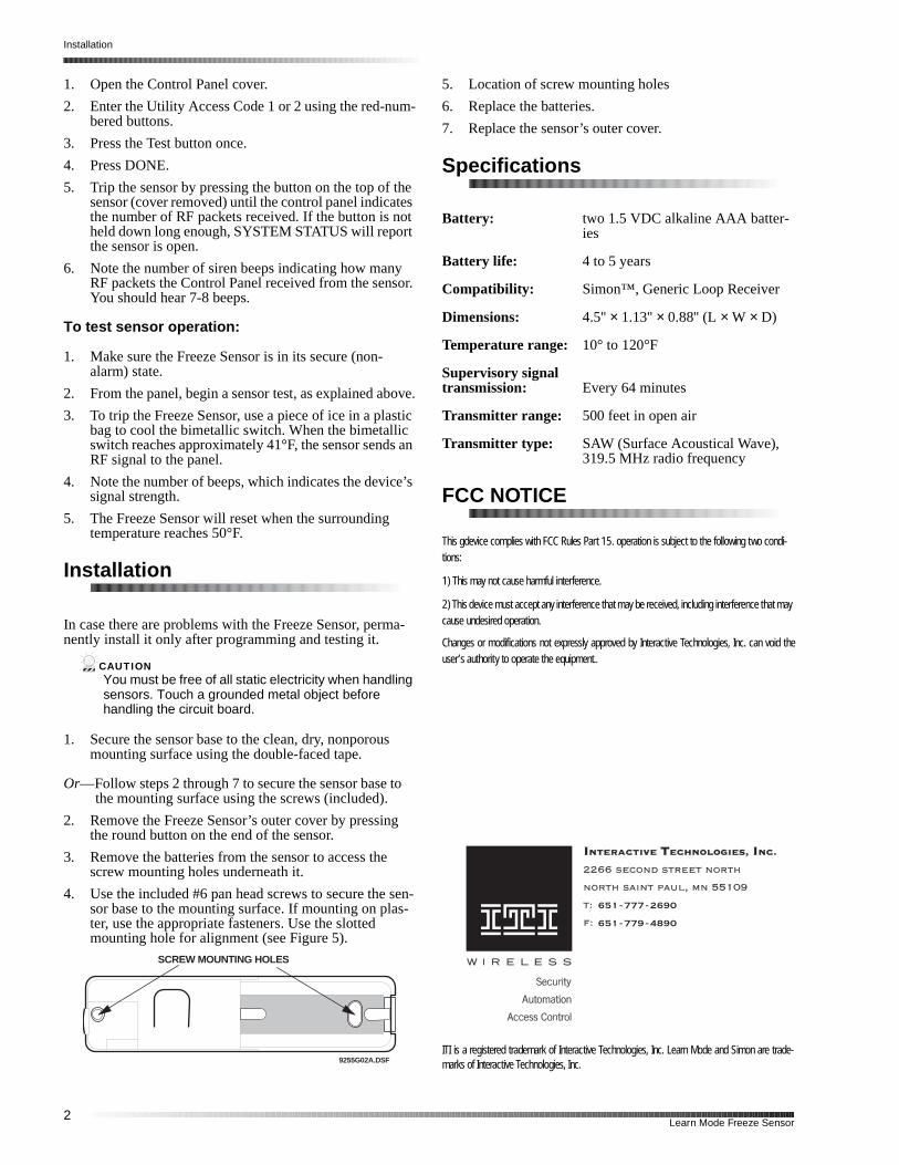
SCREW MOUNTING HOLES
9255G02A.DSF
6 5 1 - 7 7 7 - 2 6 9 0
6 5 1 - 7 7 9 - 4 8 9 0
2Learn Mode Freeze Sensor
ITI Part No. 60-744
Installation InstructionsDocument Number: 466-1539 Rev. CJanuary 2000
t
ss.
the
u l-
, -, b-
6$:#/HDUQ#0RGH#6$:#/HDUQ#0RGH#6$:#/HDUQ#0RGH#6$:#/HDUQ#0RGH#:DWHU#6HQVRU:DWHU#6HQVRU:DWHU#6HQVRU:DWHU#6HQVRU
Product Summary
The ITI SAW Learn Mode™ Water Sensor detects a water leak in a home or business. The detector is connected to the sensor by an 8-foot (2.4-meter) cable. Water that reaches both detector contact points activates the sensor, causing it to transmit an alarm signal.
The SAW 319.5 MHz transmitter has an operating range of at least 500 feet in open air (depending on panel type and installation environment). The sensor has an estimated bat-tery life of 3 to 5 years.
Tools and Equipment Needed
❑ Double-sided tape (included) for mounting the detector and sensor
❑ 1.5-inch wire (used for programming the sensor)
❑ #6 pan head screws (included) if mounting sensor with-out double-sided tape is preferred
❑ Slotted screwdriver (not included) if mounting sensor with screws
Installation Guidelines
This section describes the detector and sensor (transmitter) mounting requirements.
Detector Mounting:
❑ Install the detector on the floor for low water-level detection or on the bottom of a wall, just above the floor for higher water-level detection.
Figure 1. Detector Mounting Options
NoteThe contact points on the detector may corrode if exposed to water for more than 24 hours. Instruct your customer to temporarily remove the detector from the water, if possible, during a flood to avoid damaging the detector.
Sensor Mounting:
❑ Program and test the sensor before mounting.
❑ Install the sensor where it is easily accessible and noexposed to moisture or extreme temperatures.
❑ Locate the sensor within 100 feet of the panel when-ever possible. Although the sensor has an open-air range of at least 500 feet, the indoor range may be le
Programming
This section describes how to add (learn) the sensor into memory of compatible panels.
Simon ® Panels
1. Open the control panel cover.
2. Enter Utility Access Code 1 or 2 using the red-num-bered buttons.
3. Press Add from the Start Menu.
4. Press the Sensor/Remote button from the Main menuntil you hear the location name you wish to use withthe sensor. The panel announces the names in the folowing order:
keychain remote, touchpad remote, front door, back door, garage door, bedroom, guest room, child’s roomutility room, living room, dining room, bathroom, laundry room, kitchen, office, den, garage, special chimebasement, upstairs, downstairs, hallway, medicine cainet, closet, attic.
Each name may be used more than once.
NoteWhen adding sensors, if you wish to use a more descriptive location you may press the option button to use the compass directions (north, north east, east, south east, south, south west, west, north west).
5. Press DONE.
6. Enter the sensor type number (29) with the red num-bered keys.
Detector mounted for high level water(on wall)
Detector mounted for low level water(on floor)
TransmitterTransmitter
1SAW Learn Mode Water Sensor
Testing the Water Sensor
le r
to
r re
d
e .
o
ne
or,
st-
.
il ed.
d in
NoteIf you wish to use a sensor number other than the next available, enter a 2-digit sensor number with the red numbered keys immediately after entering the sensor type.
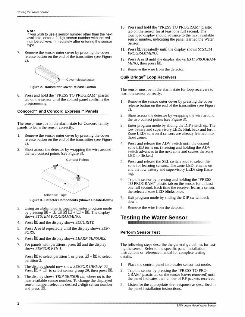
7. Remove the sensor outer cover by pressing the cover release button on the end of the transmitter (see Figure 2).
Figure 2. Transmitter Cover Release Button
8. Press and hold the “PRESS TO PROGRAM” plastic tab on the sensor until the control panel confirms the programming.
Concord™ and Concord Express™ Panels
The sensor must be in the alarm state for Concord family panels to learn the sensor correctly.
1. Remove the sensor outer cover by pressing the cover release button on the end of the transmitter (see Figure 2).
2. Short across the detector by wrapping the wire around the two contact points (see Figure 3).
Figure 3. Detector Components (Shown Upside-Down)
3. Using an alphanumeric touchpad, enter program mode by pressing 8 + 4 3 2 1 + 0 + 0. The display shows SYSTEM PROGRAMMING.
4. Press ƒ and the display shows SECURITY.
5. Press A or B repeatedly until the display shows SEN-SORS.
6. Press ƒ and the display shows LEARN SENSORS.
7. For panels with partitions, press ƒ and the display shows SENSOR PTN 1.
Press ƒ to select partition 1 or press 2 + ƒ to select partition 2.
8. The display should now show SENSOR GROUP 00. Press 2 + 9 to select sensor group 29, then press ƒ.
9. The display shows TRIP SENSOR nn, where nn is the next available sensor number. To change the displayed sensor number, select the desired 2-digit sensor number and press ƒ.
10. Press and hold the “PRESS TO PROGRAM” plastic tab on the sensor for at least one full second. The touchpad display should advance to the next availabsensor number, indicating the panel learned the WateSensor.
11. Press ‚ repeatedly until the display shows SYSTEM PROGRAMMING.
12. Press A or B until the display shows EXIT PROGRAM-MING, then press ƒ.
13. Remove the wire from the detector.
Quik Bridge ® Loop Receivers
The sensor must be in the alarm state for loop receivers learn the sensor correctly.
1. Remove the sensor outer cover by pressing the coverelease button on the end of the transmitter (see Figu2).
2. Short across the detector by wrapping the wire arounthe two contact points (see Figure 3).
3. Enter program mode by sliding the DIP switch up. Thlow battery and supervisory LEDs blink back and forthZone LEDs turn on if sensors are already learned intthose zones.
4. Press and release the ADV switch until the desired zone LED turns on. (Pressing and holding the ADV switch advances to the next zone and causes the zoLED to flicker.)
5. Press and release the SEL switch once to select thiszone for learning sensors. The zone LED remains onand the low battery and supervisory LEDs stop flash-ing.
6. Trip the sensor by pressing and holding the “PRESSTO PROGRAM” plastic tab on the sensor for at leastone full second. Each time the receiver learns a sensthe selected zone LED blinks once.
7. Exit program mode by sliding the DIP switch back down.
8. Remove the wire from the detector.
Testing the Water Sensor
Perform Sensor Test
The following steps describe the general guidelines for teing the sensor. Refer to the specific panel installation instructions or reference manual for complete testing details.
1. Place the control panel into dealer sensor test mode
2. Trip the sensor by pressing the “PRESS TO PRO-GRAM” plastic tab on the sensor (cover removed) untthe panel indicates the number of RF packets receiv
3. Listen for the appropriate siren response as describethe panel installation instructions.
Cover release button
Contact Points
Adhesive Tape
2SAW Learn Mode Water Sensor
Installation
er
d
4. Exit from dealer sensor test mode.
Test Sensor Operation
1. Make sure the Water Sensor is in the secure (non-alarm, dry) state.
2. Place the control panel into sensor test mode.
3. Trip the sensor by shorting across the detector by wrap-ping the wire around the two contact points (see Figure 3).
4. Listen for the appropriate siren response as described in the panel installation instructions.
5. Remove the wire from the two detector contact points to send a restore signal to the panel.
6. Exit from sensor test mode.
Installation
Permanently install the Water Sensor only after program-ming and testing it.
NoteOnce the sensor has been installed it is recom-mended that you test the sensor range.
To install the Water Sensor without using screws:
1. Prepare a clean, dry mounting surface for the detector and transmitter.
2. Secure the detector to the mounting surface using the double-faced tape (included).
3. Secure the Water Sensor transmitter to the mounting surface using the double-faced tape.
Figure 4. Installing the Water Sensor without Screws
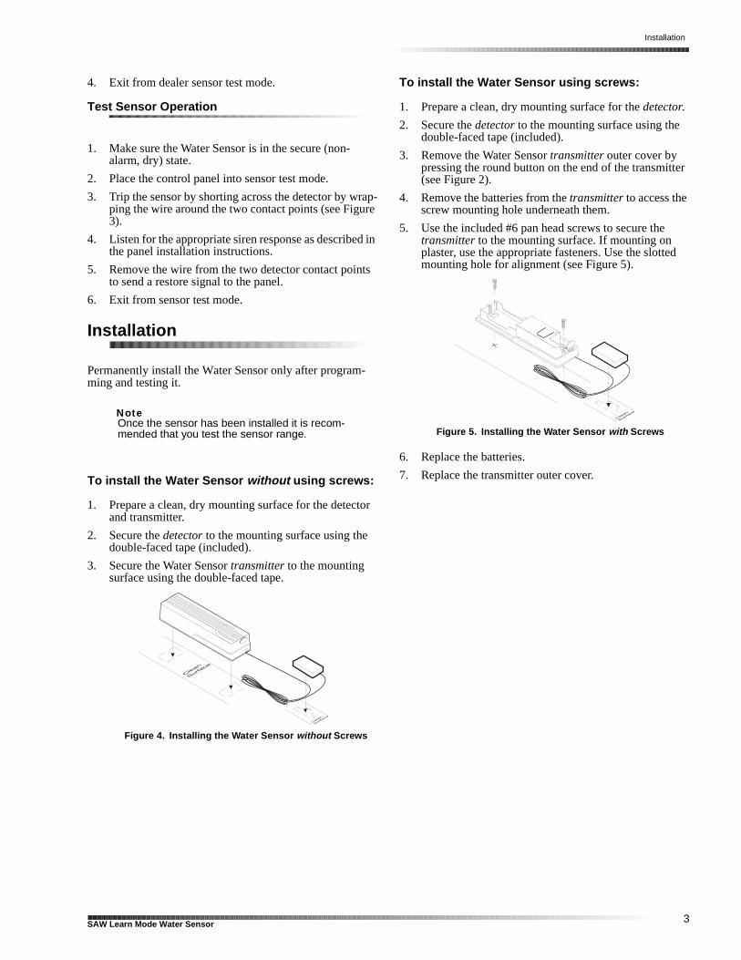
To install the Water Sensor using screws:
1. Prepare a clean, dry mounting surface for the detector.
2. Secure the detector to the mounting surface using the double-faced tape (included).
3. Remove the Water Sensor transmitter outer cover by pressing the round button on the end of the transmitt(see Figure 2).
4. Remove the batteries from the transmitter to access the screw mounting hole underneath them.
5. Use the included #6 pan head screws to secure the transmitter to the mounting surface. If mounting on plaster, use the appropriate fasteners. Use the slottemounting hole for alignment (see Figure 5).
Figure 5. Installing the Water Sensor with Screws
6. Replace the batteries.
7. Replace the transmitter outer cover.
3SAW Learn Mode Water Sensor

Specifications
Specifications
Compatibility: Simon, Concord, Concord Express, Quik Bridge Loop Receiver
Power Source: Two 1.5 V Alkaline AAA batteries
Temperature Range: 10° to 120° F
Dimensions: Detector1.80” x 0.94” x 0.50” (L x W x D)
Transmitter4.5” x 1.13” x 0.94” (L x W x D)
Notices
6 5 1 - 7 7 7 - 2 6 9 0
6 5 1 - 7 7 9 - 4 8 9 0
This device complies with Part 15 of the FCC Rules. Operation is sub-ject to the following two conditions:
This device may not cause harmful interference.
This device must accept any interference that may be received, includ-ing interference that may cause undesired operation.
Changes or modifications not expressly approved by Interactive Tech-nologies, Inc. can void the user’s authority to operate the equipment.
ITI, Simon, and Quik Bridge are registered trademarks of Interactive Technologies Inc.Learn Mode, Concord, and Concord Express are trademarks of Interactive Technologies Inc.
4SAW Learn Mode Water Sensor

Touchtalk 2-Way RF Touchpad
ce -
-
he ard
at t;
life
d is ni-
t-e p-
-
o
rs
le
Touchtalk 2-Way RF Touchpad
Document Number: 466-1595 Rev. CMarch 1999
Installation Instructions
Product Summary
The wall-mounted wireless Touchtalk 2-Way RF Touchpad combines a conventional ITI Learn Mode™ touchpad with an RF receiver, speech chip, and voiamplification circuit. The Touchtalk 2-Way RF Touchpad enables you to turn the SIMON® security system on and off while in the home, turn lights controlled bythe system on and off (all or individual lights), or turnon a system siren and call the central monitoring station if there is a non-medical emergency. It enables tuser to hear the same voice feedback as would be heat the Simon Control Panel.
The voice feedback is heard only at the touchpad this in use. If the touchpad is talking, the panel is silenwhen the panel is talking, the touchpad is silent. Thetouchpad is not a siren and will not make any alarmsounds or status beeps. This feature extends batteryto the touchpad and gives feedback only to the userwho needs it.
The Touchtalk 2-Way RF Touchpad is not superviseand has no tamper detection. A low battery conditionautomatically detected by the touchpad and commucated to the control panel.
Control Panel Compatibility: SIMON® (Only Version 2 and later [# 60-776])
60-78860-788
Installation Overview
General InformationThe Touchtalk 2-Way RF Touchpad is an alkaline batery-powered, wireless touchpad designed to providusers a convenient option for the following system oerations:
• Arm the system (doors, windows, and motion sensors)
• Arm the system with no entry delay• Disarm the system • Panic alarm• Access System Status• Turn system controlled lights on or off (all or
individual)• Open the garage door or turn outside lights on
Note: The voice feedback is heard only at the touch-pad that is in use. If the touchpad is talking, the panel is silent; when the panel is talking, the touchpad is silent. The touchpad is not a siren and will not make any alarm sounds or status beeps. This feature extends battery life to the touchpad and gives feedback only to the user who needs it.
Installation GuidelinesUse the following guidelines when adding this touchpad to the system:
• Touchtalk 2-Way RF Touchpads are learned intthe Control Panel as sensors.
• They are programmed as non-supervised sensousing sensor type 01, 03, 06 or 07.
• Each learned Touchpad uses one of the availabsensor numbers (24 total sensors/zones can beused with this security panel).
• The Touchtalk 2-Way RF Touchpad is mountedon the wall.
Page 1

Page
Touchtalk 2-Way RF Touchpad
n-ou
g
m
ro-e-
e F e
-i-
Programming
For complete programming instructions, refer to the SIMON® installation instructions. General guidelines for programming this sensor are:
1. Open the control panel cover.2. Enter Utility Access Code 1 or 2 using the red-
numbered buttons.3. Press Add from the Start Menu.4. Press the Sensor/Remote button from the Main
menu until you hear “touchpad remote.”
The order of names the Control Panel uses are: keychain remote, touchpad remote, front door, back door, garage door, bedroom, guest room, child’s room, utility room, living room, dining room, bathroom, laundry room, kitchen, office, den, garage, special chime, basement, upstairs, downstairs, hallway, medicine cabinet, closet, attic. Each name may be used more than once.
5. Press DONE.6. Enter the sensor type number (01, 03, 06, or 07)
with the red- numbered buttons.
Note: If you wish to use a sensor number other than the next available, enter a 2 digit sensor number with the red numbered keys immediately after entering the sensor type.
7. Press and hold the 2 emergency buttons to trip the sensor.
Testing Touchtalk 2-Way RF Touchpads
Perform Sensor Test
The touchpad is sensitive to its orientation to the Cotrol Panel. For that reason, it is recommended that ytest the touchpad prior to mounting it on a wall.
The following steps describe the guidelines for testinsensors.
1. Open the Control Panel cover. 2. Enter the Utility Access Code 1 or 2 using the
red-numbered buttons.3. Press the Test button once.4. Press DONE.5. Trip the touchpad by pressing and holding the 2
emergency buttons until the Control Panel indi-cates the number of RF packets received.
6. Note the number of siren beeps indicating how many RF packets the Control Panel received frothe sensor. You should hear 7-8 beeps.
We recommend that you test the touchpad after all pgramming is completed and whenever a touchpad-rlated problem occurs.
If a Touchpad Fails the Sensor Test
If sirens do not beep when a touchpad is tripped, usan ITI RF Sniffer (60-401) test tool to verify that thetouchpad is transmitting. Constant beeps from the RSniffer indicate a runaway (faulty) touchpad. Replacthe touchpad.
To improve sensor communication, you can:• reposition the touchpad• relocate the touchpad• if necessary, replace the touchpad
To reposition a touchpad:1. Rotate the touchpad and test for improved com
munication at 90 and 180 degrees from the orignal position.
2. If poor communication persists, relocate the touchpad as described as follows.
2

Touchtalk 2-Way RF Touchpad
l
l
e
To relocate a touchpad:1. Test the touchpad a few inches from the original
position.2. Increase the distance from the original position
and retest until an acceptable location is found.3. Mount the touchpad in the new location.4. If no location is acceptable, replace the touchpad.
To replace a touchpad:1. Test a known good touchpad at the same location.2. If the transmission beeps remain below the mini-
mum level, avoid mounting a touchpad at that location.
3. If the replacement touchpad functions, contact ITI for repair or replacement of the problem touchpad.
Mounting the Touchtalk 2-Way RF Touchpad
To mount the touchpad on a wall, do the following:
1. Open the door of the touchpad.2. Gently pull down on the tab at the bottom of the
touchpad to separate the touchpad body from the touchpad mounting plate.
3. Use the two screws included with the touchpad to attach the touchpad to the wall.
4. Reattach the touchpad to the mounting plate.
Perform Sensor Test After Mounting the Touchpad
Repeat the steps listed in the perform sensor test para-graph on the previous page.
Note: While the sensor test is a valuable installation and service tool, it only tests sensor operation for the current conditions. You should perform a sensor test after any change in environment, equipment, or programming.
Test Touchpad operation by pressing the buttons as de-scribed below:
1. Numeric Buttons (0 - 9) - Used to enter an access code or turn individual lights on or off.
2. Disarm Button -The Control Panel is disarmed to level 1. Doors, Windows, and Motion Sensors are disarmed. Disarm also requires the access code to be entered.
3. ARM Doors & Windows Button - The Control Panel is armed to level 2.
4. ARM Motion Sensors Button - The Control Paneis armed to level 3. If the ARM Doors & Win-dows button was previously pressed, the ControPanel is armed to level 4 (Doors/Windows and Motion Sensors armed).
5. Lights On Button - Pressing this button twice quickly, activates all lights controlled by the sys-tem.
6. Lights Off Button - Pressing this button twice quickly, turns off all lights controlled by the sys-tem.
7. Emergency Buttons - If learned in as sensor typ01-Intrusion, 03-Silent, 06 or 07-Emergency, when pressed simultaneously, will activate alarmreports to the central station.
SpecificationsPower source: 3 AAA Alkaline batteries
Typical battery life: 3 year
Operating temperature range: 0° to 120° F
Dimensions: H = 5.25” x W = 3.5” x Depth =1”
FCC NOTICE
This device complies with FCC Rules Part 15. operation is subject to the following two
conditions:
1) This may not cause harmful interference.
2) This device must accept any interference that may be received, including interference
that may cause undesired operation.
Changes or modifications not expressly approved by Interactive Technologies, Inc. can void the user’s authority to operate the equipment.
Changes or modifications not expressly approved by Interactive Technologies, Inc. can void the users’ authority to operate the equipment.
6 5 1 - 7 7 7 - 2 6 9 0
6 5 1 - 7 7 9 - 4 8 9 0
Page 3

Page
Touchtalk 2-Way RF Touchpad
4