Embed Size (px)
Citation preview

APGR
Doc #9004131Rev A3, 01/18
PT-L Pressure TransducerUser Manual
Amplified Output Series
ii Tel: 1/888/525-7300 • Fax: 1/435/753-7490 • www.apgsensors.com • [email protected]
Table of Contents
Introduction ................................................................................................................ iii
Warranty and Warranty Restrictions .................................................................... iv
Chapter 1: Specifications and Options..................................................................... 1 Dimensions ........................................................................................................................................1 Specifications ................................................................................................................................... 2 Model Number Configurator .......................................................................................................... 3 Electrical Connectors, Pinout Table, and Supply Power Table .............................................. 4 Wiring Diagrams .............................................................................................................................. 5
Chapter 2: Installation and Removal Procedures and Notes ..............................5 Tools Needed ..................................................................................................................................... 5 Mounting Instructions ................................................................................................................... 6 Electrical Installation ..................................................................................................................... 6 Removal Instructions ..................................................................................................................... 6
Chapter 3: Maintenance .............................................................................................7 General Care ...................................................................................................................................... 7 Zero Trimming ...............................................................................................................................7-8 Re-Calibration ................................................................................................................................... 8 Repair and Returns .......................................................................................................................... 8

iiiTel: 1/888/525-7300 • Fax: 1/435/753-7490 • www.apgsensors.com • [email protected]
IntroductionThank you for purchasing a PT-L amplified series pressure transmitter from APG. We appreciate your business! Please take a few minutes to familiarize yourself with your PT-L and this manual.
The PT-L series of pressure transmitters offers economical reliability over a wide range of pressures. The small size, integrated electronics, wide operating temperature range, and durability, make the PT-L the perfect instrument with an amplified output signal for static and dynamic pressure measurements.
Reading your labelEvery APG instrument comes with a label that includes the instrument’s model number, part number, serial number, and a wiring pinout table. Please ensure that the part number and pinout table on your label match your order.

iv Tel: 1/888/525-7300 • Fax: 1/435/753-7490 • www.apgsensors.com • [email protected]
Warranty and Warranty RestrictionsThis product is covered by APG’s waranty to be free from defects in material and workmanship under normal use and service of the product for 24 months. For a full explanation of our Warranty, please visit https://www.apgsensors.com/about-us/terms-conditions. Contact Technical Support to recieve a Return Material Authorization before shipping your product back.
Scan the QR code below to read the full explanation of our Warranty on your tablet or smartphone.
1Tel: 1/888/525-7300 • Fax: 1/435/753-7490 • www.apgsensors.com • [email protected]
Chapter 1: Specifications and Options
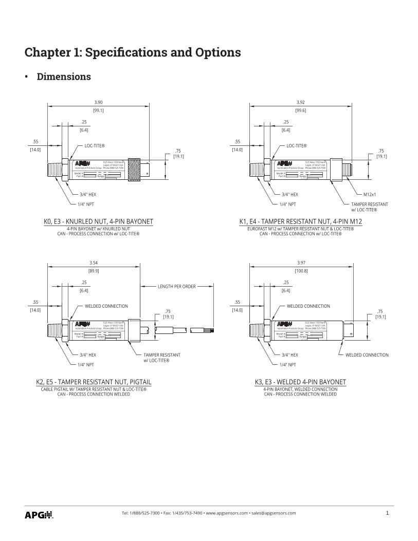
• Dimensions
.55
[14.0]
.25
[6.4]
3.90
[99.1]
.75 [19.1]
3/4" HEX
1/4" NPT
K0, E3 - KNURLED NUT, 4-PIN BAYONET
Model #:Part #: Range:
Automation Products Group
1025 West 1700 NorthLogan, UT 84321 USAPhone (888) 525-7300
LOC-TITE®
4-PIN BAYONET w/ KNURLED NUTCAN - PROCESS CONNECTION w/ LOC-TITE®
.55
[14.0]
.25
[6.4]
3.92
[99.6]
3/4" HEX
1/4" NPT
M12x1
K1, E4 - TAMPER RESISTANT NUT, 4-PIN M12
.75 [19.1]
Model #:Part #: Range:
Automation Products Group
1025 West 1700 NorthLogan, UT 84321 USAPhone (888) 525-7300
TAMPER RESISTANTw/ LOC-TITE®
LOC-TITE®
EUROFAST M12 w/ TAMPER RESISTANT NUT & LOC-TITE®CAN - PROCESS CONNECTION w/ LOC-TITE®
.55
[14.0]
.25
[6.4]
3.54
[89.9]
LENGTH PER ORDER
3/4" HEX
1/4" NPT
K2, E5 - TAMPER RESISTANT NUT, PIGTAIL
.75 [19.1]
Model #:Part #: Range:
Automation Products Group
1025 West 1700 NorthLogan, UT 84321 USAPhone (888) 525-7300
CABLE PIGTAIL W/ TAMPER RESISTANT NUT & LOC-TITE®CAN - PROCESS CONNECTION WELDED
TAMPER RESISTANTw/ LOC-TITE®
WELDED CONNECTION.55
[14.0]
.25
[6.4]
3.97
[100.8]
.75 [19.1]
3/4" HEX
1/4" NPT
K3, E3 - WELDED 4-PIN BAYONET
Model #:Part #: Range:
Automation Products Group
1025 West 1700 NorthLogan, UT 84321 USAPhone (888) 525-7300
4-PIN BAYONET, WELDED CONNECTIONCAN - PROCESS CONNECTION WELDED
WELDED CONNECTION
WELDED CONNECTION
2 Tel: 1/888/525-7300 • Fax: 1/435/753-7490 • www.apgsensors.com • [email protected]
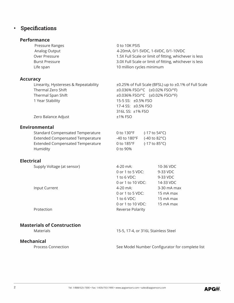
Performance Pressure Ranges 0 to 10K PSIS Analog Output 4-20mA, 0/1-5VDC, 1-6VDC, 0/1-10VDC Over Pressure 1.5X Full Scale or limit of fitting, whichever is less Burst Pressure 3.0X Full Scale or limit of fitting, whichever is less Life span 10 million cycles minimum
Accuracy Linearity, Hystereses & Repeatability ±0.25% of Full Scale (BFSL) up to ±0.1% of Full Scale Thermal Zero Shift ±0.036% FSO/°C (±0.02% FSO/°F) Thermal Span Shift ±0.036% FSO/°C (±0.02% FSO/°F) 1 Year Stability 15-5 SS: ±0.5% FSO 17-4 SS: ±0.5% FSO 316L SS: ±1% FSO Zero Balance Adjust ±1% FSO
Environmental Standard Compensated Temperature 0 to 130°F (-17 to 54°C) Extended Compensated Temperature -40 to 180°F (-40 to 82°C) Extended Compensated Temperature 0 to 185°F (-17 to 85°C) Humidity 0 to 90%
Electrical Supply Voltage (at sensor) 4-20 mA: 10-36 VDC 0 or 1 to 5 VDC: 9-33 VDC 1 to 6 VDC: 9-33 VDC 0 or 1 to 10 VDC: 14-33 VDC Input Current 4-20 mA: 3-30 mA max 0 or 1 to 5 VDC: 15 mA max 1 to 6 VDC: 15 mA max 0 or 1 to 10 VDC: 15 mA max Protection Reverse Polarity
Masterials of Construction Materials 15-5, 17-4, or 316L Stainless Steel
Mechanical Process Connection See Model Number Configurator for complete list
• Specifications
3Tel: 1/888/525-7300 • Fax: 1/435/753-7490 • www.apgsensors.com • [email protected]
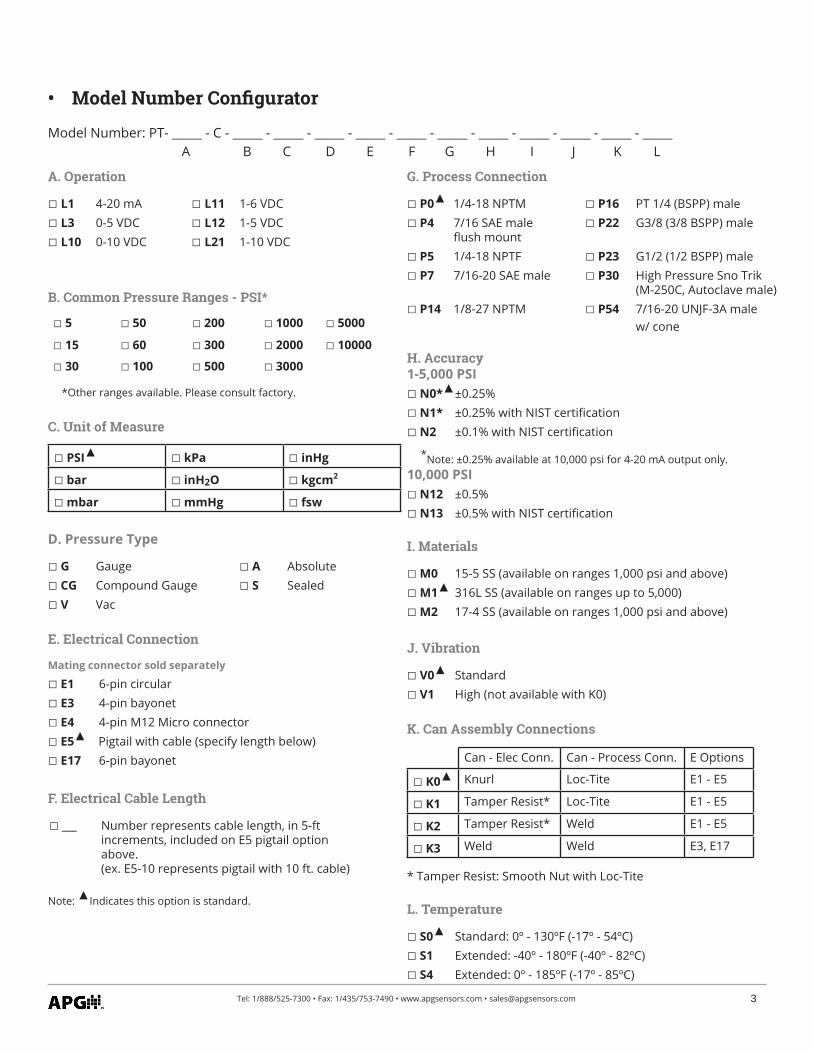
• Model Number Configurator
Model Number: PT- _____ - C - _____ - _____ - _____ - _____ - _____ - _____ - _____ - _____ - _____ - _____ - _____ A B C D E F G H I J K L
A. Operation
L1 4-20 mA L11 1-6 VDC L3 0-5 VDC L12 1-5 VDC L10 0-10 VDC L21 1-10 VDC
B. Common Pressure Ranges - PSI*
5 50 200 1000 5000
15 60 300 2000 10000
30 100 500 3000
*Other ranges available. Please consult factory.
C. Unit of Measure
PSI kPa inHg
bar inH2O kgcm2
mbar mmHg fsw
D. Pressure Type
G Gauge A Absolute CG Compound Gauge S Sealed V Vac
E. Electrical Connection
Mating connector sold separately
E1 6-pin circular E3 4-pin bayonet E4 4-pin M12 Micro connector E5 Pigtail with cable (specify length below) E17 6-pin bayonet
F. Electrical Cable Length
___ Number represents cable length, in 5-ft increments, included on E5 pigtail option above.(ex. E5-10 represents pigtail with 10 ft. cable)
Note: Indicates this option is standard.
G. Process Connection
P0 1/4-18 NPTM P16 PT 1/4 (BSPP) male P4 7/16 SAE male P22 G3/8 (3/8 BSPP) male flush mount P5 1/4-18 NPTF P23 G1/2 (1/2 BSPP) male P7 7/16-20 SAE male P30 High Pressure Sno Trik (M-250C, Autoclave male) P14 1/8-27 NPTM P54 7/16-20 UNJF-3A male w/ cone
H. Accuracy1-5,000 PSI N0* ±0.25% N1* ±0.25% with NIST certification N2 ±0.1% with NIST certification
*Note: ±0.25% available at 10,000 psi for 4-20 mA output only.10,000 PSI N12 ±0.5% N13 ±0.5% with NIST certification
I. Materials
M0 15-5 SS (available on ranges 1,000 psi and above) M1 316L SS (available on ranges up to 5,000) M2 17-4 SS (available on ranges 1,000 psi and above)
J. Vibration
V0 Standard V1 High (not available with K0)
K. Can Assembly Connections
Can - Elec Conn. Can - Process Conn. E Options
K0 Knurl Loc-Tite E1 - E5
K1 Tamper Resist* Loc-Tite E1 - E5
K2 Tamper Resist* Weld E1 - E5
K3 Weld Weld E3, E17
* Tamper Resist: Smooth Nut with Loc-Tite
L. Temperature
S0 Standard: 0º - 130ºF (-17º - 54ºC) S1 Extended: -40º - 180ºF (-40º - 82ºC) S4 Extended: 0º - 185ºF (-17º - 85ºC)
4 Tel: 1/888/525-7300 • Fax: 1/435/753-7490 • www.apgsensors.com • [email protected]
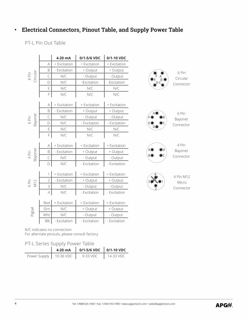
• Electrical Connectors, Pinout Table, and Supply Power Table
PT-L Pin Out Table
6 Pi
n Ci
rcul
ar
4-20 mA 0/1-5/6 VDC 0/1-10 VDCA + Excitation + Excitation + Excitation
B - Excitation + Output + Output
C N/C - Output - Output
D N/C -Excitation -Excitation
E N/C N/C N/C
F N/C N/C N/C
6 Pi
n Ba
yone
t
A + Excitation + Excitation + Excitation
B - Excitation + Output + Output
C N/C - Output - Output
D N/C - Excitation - Excitation
E N/C N/C N/C
F N/C N/C N/C
4 Pi
nBa
yone
t A + Excitation + Excitation + Excitation
B - Excitation + Output + Output
C N/C - Output - Output
D N/C - Excitation - Excitation
4 Pi
nM
12
1 + Excitation + Excitation + Excitation
2 - Excitation + Output + Output
3 N/C - Output - Output
4 N/C - Excitation - Excitation
Pigt
ail
Red + Excitation + Excitation + Excitation
Grn N/C + Output + Output
Wht N/C - Output - Output
Blk - Excitation - Excitation - Excitation
N/C indicates no connectionFor alternate pinouts, please consult factory
PT-L Series Supply Power Table4-20 mA 0/1-5/6 VDC 0/1-10 VDC
Power Supply 10-36 VDC 9-33 VDC 14-33 VDC
6 PinBayonet
Connector
4 Pin M12 Micro
Connector
AF
ED
B
C
+
3
2
4
1
4 PinBayonet
Connector
A
B
D
C
6 PinCircular
Connector
AFE
DB
C
5Tel: 1/888/525-7300 • Fax: 1/435/753-7490 • www.apgsensors.com • [email protected]
– Excitation
+ Excitation
4-20 mACurrent
Loop
LR
+VDC
PT-L14-20 mA Output
ProcessController
V+
PT-L3/10/11/12/21Voltage Output VDC Source
+ Excitation
- Excitation
+ Output
- Output
V-
Signal Receiver
Input+
Input-
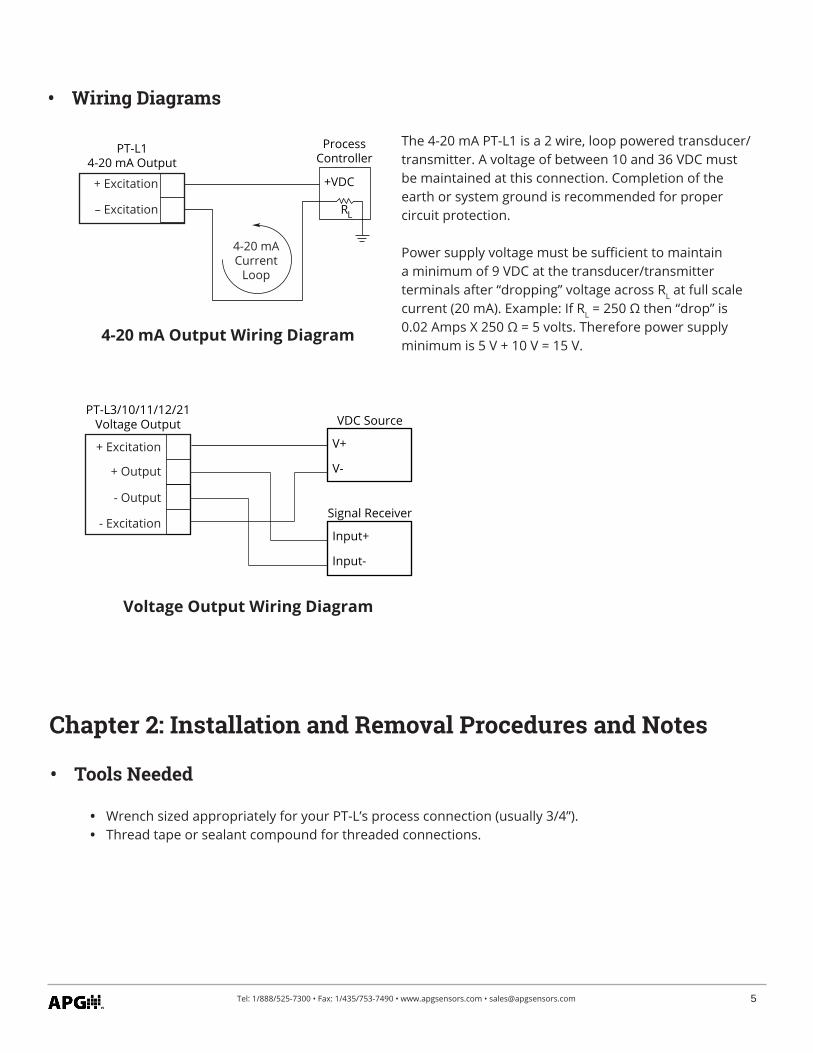
• Wiring Diagrams
4-20 mA Output Wiring Diagram
Voltage Output Wiring Diagram
The 4-20 mA PT-L1 is a 2 wire, loop powered transducer/transmitter. A voltage of between 10 and 36 VDC must be maintained at this connection. Completion of the earth or system ground is recommended for proper circuit protection.
Power supply voltage must be sufficient to maintain a minimum of 9 VDC at the transducer/transmitter terminals after “dropping” voltage across RL at full scale current (20 mA). Example: If RL = 250 Ω then “drop” is 0.02 Amps X 250 Ω = 5 volts. Therefore power supply minimum is 5 V + 10 V = 15 V.
Chapter 2: Installation and Removal Procedures and Notes
• Wrench sized appropriately for your PT-L’s process connection (usually 3/4”).• Thread tape or sealant compound for threaded connections.
• Tools Needed
6 Tel: 1/888/525-7300 • Fax: 1/435/753-7490 • www.apgsensors.com • [email protected]
• Mounting Instructions
• Check the pinout table on your PT-L against your order.• Check that your electrical system wiring matches the pinout table on your PT-L.• For instruments with connectors, make the connection. For instruments with pigtails, run the cable to
a junction box in a suitable location to connect to your system.
• Electrical Installation
Removing your PT-L from service must be done with care. It’s easy to create an unsafe situation, or damage your sensor, if you are not careful to follow these guidelines:
• Make sure the pressure is completely removed from the line or vessel where your sensor is installed. Follow any and all procedures for safely isolating any media contained inside the line or vessel.
• Remove the sensor with an appropriately sized wrench (per your process connection).• Carefully clean the sensor’s fitting and diaphragm of any debris (see General Care) and inspect for
damage.• Store your sensor in a dry place, at a temperature between -40° F and 180° F.
• Removal Instructions
Mounting your pressure transducer is easy if you follow a few simple steps:• Never over-tighten the sensor. This can compress the diaphragm, changing how it reacts to pressure.
In all cases, tighten the sensor as little as possible to create an adequate seal. On straight threads, tighten only until you feel the o-ring compress - making sure you don’t damage or extrude the o-ring.
• Always use thread tape or sealant compound on tapered threads. Wrap thread tape in the opposite direction of the threads so it does not unravel as you screw the sensor into place. Unraveling can cause uneven distribution and seal failure. For straight threads use an o-ring.
• Always start screwing in your sensor by hand to avoid cross-threading. Thread failure can be a problem if you damage threads by over-tightening them or by crossing threads.
DANGER: Removing your PT-L Pressure Transmitter while there is still pressure in the line could result in injury or death.
7Tel: 1/888/525-7300 • Fax: 1/435/753-7490 • www.apgsensors.com • [email protected]
Your PT-L series pressure transmitter is very low maintenance and will need little care as long as it was installed correctly. However, in general, you should:
• Keep the transmitter and the area around it generally clean. • Avoid applications for which the transmitter was not designed, such as extreme temperatures, contact
with incompatible corrosive chemicals, or other damaging environments.• Inspect the threads whenever you remove the transmitter from duty or change its location.• Avoid touching the diaphragm. Contact with the diaphragm, especially with a tool, could permanently
shift the output and ruin accuracy.• Clean the diaphragm or the diaphragm bore with extreme care. If using a tool is required, make sure it
does not touch the diaphragm.
Chapter 3: Maintenance
• General Care
• Zero Trimming
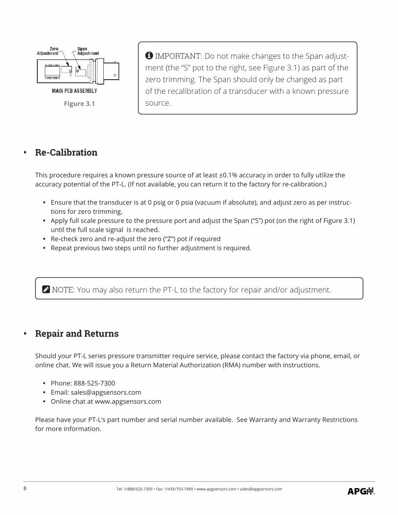
If it becomes necessary to re-adjust “zero”, this can be accomplished by adjusting the trimpot marked “Z”. An ideal zero is indicated by an output of 4 mA, 0 VDC or 1 VDC, depending on your model.
• Remove the knurled nut. If your transducer does not have a knurled nut, your transducer can not be field adjusted. You can return the transducer to the factory for repair and/or adjustment.
• Carefully remove the connector or pigtail from the body of the transducer and pull it all the way out so that the amplifier board is exposed. Do not over extend the ribbon cable that attaches the amplifier board to the sensor.
• Reconnect the device with the loop powered circuit and have access to a method of monitoring the output of the transducer.
• Ensure that the transducer is at 0 psig or 0 psia (vacuum if absolute).• Using a jewelers screwdriver or suitable instrument, adjust the “Z” pot (See Figure 3.1) until you have
zero output.
IMPORTANT: Any contact with the diaphragm can permanently damage the sensor. Use extreme caution.
NOTE: Non-sealed sensors have a small vent hole that must not be covered or closed. Covering, closing, or otherwise sealing this hole will prevent proper sensor operation.
8 Tel: 1/888/525-7300 • Fax: 1/435/753-7490 • www.apgsensors.com • [email protected]
Should your PT-L series pressure transmitter require service, please contact the factory via phone, email, or online chat. We will issue you a Return Material Authorization (RMA) number with instructions.
• Phone: 888-525-7300• Email: [email protected]• Online chat at www.apgsensors.com
Please have your PT-L’s part number and serial number available. See Warranty and Warranty Restrictions for more information.
• Repair and Returns
IMPORTANT: Do not make changes to the Span adjust-ment (the “S” pot to the right, see Figure 3.1) as part of the zero trimming. The Span should only be changed as part of the recalibration of a transducer with a known pressure source.Figure 3.1
This procedure requires a known pressure source of at least ±0.1% accuracy in order to fully utilize the accuracy potential of the PT-L. (If not available, you can return it to the factory for re-calibration.)
• Ensure that the transducer is at 0 psig or 0 psia (vacuum if absolute), and adjust zero as per instruc-tions for zero trimming.
• Apply full scale pressure to the pressure port and adjust the Span (“S”) pot (on the right of Figure 3.1) until the full scale signal is reached.
• Re-check zero and re-adjust the zero (“Z”) pot if required• Repeat previous two steps until no further adjustment is required.
• Re-Calibration
NOTE: You may also return the PT-L to the factory for repair and/or adjustment.

9Tel: 1/888/525-7300 • Fax: 1/435/753-7490 • www.apgsensors.com • [email protected]

Automation Products Group, Inc.Tel: 1/888/525-7300 • Fax: 1/435/753-7490 • www.apgsensors.com • [email protected]
APGR