Embed Size (px)
Citation preview

SASH WINDOW MANUFACTURE
Timothy Nott Designs 1987
Page
1) Nomenclature and general procedure 2
2) Measurement and sectional dimensions 2
3) Making the casing 4
4) Setting out the sashes 7
5) Making the sashes 8
6) Fitting together 13
A note on the 2010 edition
This document was originally written on a golf ball typewriter, and hand illustrated in 1987, but the print has survived somewhat better than my memory of it. The tenoner mentioned was a Sedgwick 3-head, and operated much as my current one does. The spindle moulder was something ancient, nameless, and indestructible, likewise the mortiser and planer.
There are a few mistakes and confusions. Fig 1 doesn’t make clear that the window usually sits in a rebate in the brickwork (or stonework for the wealthy) so you only see the part of the outer facing that projects inside the pulley stiles or head. The cill sits flat on the masonry.
The mention on page 9 of an adjustable rebating block does not stir any memories, but I think it must be one of those many scary things of the age that no longer trouble us, along with French-head cutters, dado sets and Mrs Thatcher.
You are free to download, copy, print, light the fire with this document, but copyright remains mine. I hope it is of some use.
Tim Nott, March 2010

Sash Windows
Page 2
1. Nomenclature and general procedure.
1.1 Nomenclature.
The parts of the window are referred to in the text by the names shown in fig. 1.
1.2 General procedure.
Some of this is screamingly obvious. Some is not. Read through the whole thing first, then read through each section completely before you start on that stage.
Often we will be making more than one window, and it will make sense to carry out each stage for all the windows, e.g. machine all the cills, tenon all the glazing bars or whatever. These instructions have been written on a “minimum risk” principle, so that minor cock-ups can be rectified with the minimum of resetting and hassle, so it is important that each stage, particularly in the making of the sashes, is completed and the results checked before moving on to the next stage. Most obviously, straightness and flatness of each component is essential. Large knots should be avoided where possible, especially in delicate sections, such as glazing bars. It is wise to make spare planed stock for glazing bars.
It is important also to number and label each component of each window, For instance four sets of sashes, all slightly different, and having 6 panes per sash will consist of 72 components. There is only one way to assemble these correctly. There are at least 48 wrong combinations. Similarly, components should be face marked, and each one checked as it is put into the mortiser, tenoner or spindle moulder. It is only too easy, when machining a large number of pieces, to lose concentration, and, say cut a moulding on the wrong edge. If this is done, and goes undetected until assembly It will mean resetting machines etc, with a disproportionate amount of time lost to rectify a small mistake.
Pricing on sash windows is tight but we have the equipment and the skill, and should be able to construct them competitively, profitably and well.
This guide is subject to updating and all suggestions and bright ideas will be gratefully received,
2. Measurement and sectional dimensions.
2.1 Measurement.
Sash windows are usually measured from the opening on the external face of the building, so that the given width is the distance between the inside faces of the pulley stiles, and the height is the distance from the inside of the head to the underside of the cill (see fig. 1).

Sash Windows
Page 3

Sash Windows
Page 4
2.2 Sectional dimensions.
With the exception of very large, very small or just plain weird windows, the basic sections will vary little, except for the width of the glazing bars, bottom rail and meeting rails The width is measured in the plane of the sash, the thickness is measured through the section of the sash, so a 18mm x 45 mm glazing bar is 45mm thick and 18mm wide, Normal sections are shown on figs. 2 & 3. The moulding to the inside of the sashes is normally an Ogee or “Lamb’s tongue”.
3. Making the casing.
3.1 Cills
Cills are normally ex 150mm x 75mm softwood (occasionly hardwood), and are generally machined to the section shown in fig 2. Allow +190mm (usually) to the length for the pulley boxes.
3.2 Pulley stiles and head.
These are generally finished 21 to 28mm x 100mm, with a groove in the pulley stiles 9.5mm wide (or to suit parting bead bought in) x 8mm deep. Remember to add 190mm to the length of the head to span the pulley boxes (see fig. 2).
The pulley stiles are housed in cross—cut grooves in the cill and head, the distance between the inner edges of the grooves being the given width of the window. The grooves should be no more than half the thickness of the timber, and the length of the pulley stiles worked out from the given height, as follows:
Length of timber = Given height + depth of groove in head - thickness of remainder of cill.
3.3 Pockets and pulleys.
The pockets can then be cut in a position and of a height to facilitate removal of the weights. It will often be possible to copy these from the old windows. To make life easy, these will generally be cut across from the inside of the pulley stile and down through the parting bead groove. The top is simply rebated, the bottom has a bevelled rebate. Until someone comes out with a better idea, these rebates are cut with a handsaw from each side, and the long grain split at the rebate. (see fig 1). The pulleys are centered vertically between the edge of the stile and the groove and usually centered horizontally 100-150mm below the head.

Sash Windows
Page 5

Sash Windows
Page 6

Sash Windows
Page 7
3.4 External and internal facings.
The internal facing is generally finished to 21mm x 95mm, and the external to 21mm x 113mm, though the external can be thinner, say 15-18mm. II the internal facing is, thinner, then the pulley stile must be made correspondingly wider to accommodate the staff bead. This does have the advantage that the staff bead then covers the joint.
The length of the vertical facings is the given window height + the width of the internal facing, and the horizontals fit between them.
The cill and head can now be cut out so that the facings finish flush. Usually the external facing, where it joins the cill, is cut back to allow the draining of rainwater (see fig. 1).
3.5 Assembly.
The casing can now be assembled, the head and cill being nailed and glued to the stiles, and the facings being glued and nailed and or biscuited, Don’t nail or glue the pockets! Thin plywood linings can then be pinned across the gap between the two facings, forming a rigid box. If the frame is to be preserved, and the sashes not, it is as well to do this now to save waiting at the priming stage.
4. Setting out the sashes
4.1 Making a rod.
Make a plywood rod that is a full size cross sectional drawing of the window casing, marking in the head, cill, facings and parting bead (see section— fig. 1).
Draw in the bottom and top rail sections. Note the bottom rail is on the inner sash (and allow for the bevel), the top on the outer. Measure the distance between them and subtract from this the width (see section 2.2) of the meeting rails. Divide the result by two and this will give the distance between the top and bottom rail and the upper and lower meeting rails respectively. The object is to get each opening the same size— not only does this then look right, it makes life easier for the glazier. If there are to be horizontal glazing bars (usually one per sash), repeat this exercise, i.e. measure rail to rail on each sash (which should be the same!), subtract width of glazing bar and divide by two. Label the rod with the window number.
If there are complicated glazing bars it may be advisable to make a horizontal rod, but this can usually be done straight on to one of the rails and copied on to the others.
Sash Windows
Page 8
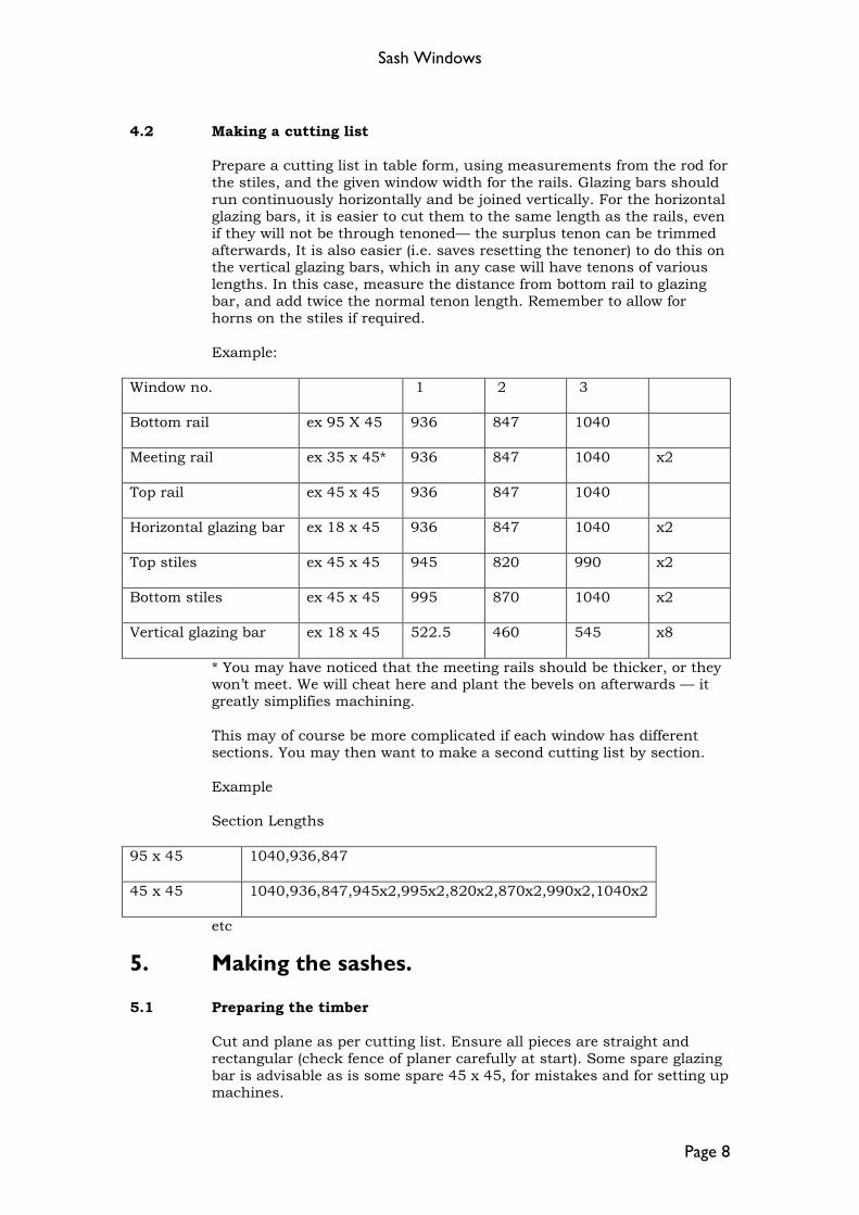
4.2 Making a cutting list
Prepare a cutting list in table form, using measurements from the rod for the stiles, and the given window width for the rails. Glazing bars should run continuously horizontally and be joined vertically. For the horizontal glazing bars, it is easier to cut them to the same length as the rails, even if they will not be through tenoned— the surplus tenon can be trimmed afterwards, It is also easier (i.e. saves resetting the tenoner) to do this on the vertical glazing bars, which in any case will have tenons of various lengths. In this case, measure the distance from bottom rail to glazing bar, and add twice the normal tenon length. Remember to allow for horns on the stiles if required.
Example:
Window no. 1 2 3
Bottom rail ex 95 X 45 936 847 1040
Meeting rail ex 35 x 45* 936 847 1040 x2
Top rail ex 45 x 45 936 847 1040
Horizontal glazing bar ex 18 x 45 936 847 1040 x2
Top stiles ex 45 x 45 945 820 990 x2
Bottom stiles ex 45 x 45 995 870 1040 x2
Vertical glazing bar ex 18 x 45 522.5 460 545 x8
* You may have noticed that the meeting rails should be thicker, or they won’t meet. We will cheat here and plant the bevels on afterwards — it greatly simplifies machining.
This may of course be more complicated if each window has different sections. You may then want to make a second cutting list by section.
Example
Section Lengths
95 x 45 1040,936,847
45 x 45 1040,936,847,945x2,995x2,820x2,870x2,990x2,1040x2
etc
5. Making the sashes.
5.1 Preparing the timber
Cut and plane as per cutting list. Ensure all pieces are straight and rectangular (check fence of planer carefully at start). Some spare glazing bar is advisable as is some spare 45 x 45, for mistakes and for setting up machines.
Sash Windows
Page 9
Face mark and label each piece. For argument’s sake we will call the face of each piece that which faces into the room. It also helps to mark the inside edge, i.e. the one that will be moulded. Keep defects on the outside edge, i.e. the side that faces the pulley stiles. Remember that these will shortly be moulded and rebated so label where the surface will remain!
Mark out the lengths and mortises of all the stiles (not forgetting any horns). Cut the horizontal rails and vertical glazing bars exactly to length. Mark out mortises on these if applicable.
5.2 Spindle moulder 1
Set up the spindle moulder. The moulding cutters go in the fixed knife block, and the straight (rebate) cutters go in the adjustable knife block. Put the moulding block on the bottom of the spindle, followed by the special spacer, followed by the rebating block. How the fence and rebating knives are set depends on the thickness of the glazing bars.
If there are no glazing bars, or the glazing bars are 21mm or more wide, then set the fence to give 10mm depth of moulding (see fig. 3). Set the rebate cutters to give 8mm depth of cut.
If the glazing bars are l5mm—l8mm, set the fence to give 9mm depth of moulding, (a little more if exactly 18mm), and the rebate cutters to give 6mm depth of cut.
If the glazing bars are less than 15mm set the rebate cutters to leave at least 3mm on the glazing bars—e.g. a 12mm glazing bar would have a 4.5mm rebate.
In the last two cases, the glazing bars will end up reduced in thickness, i.e. the moulded sections will join up to form a “Lamb’s tongue”. More about this later.
Set the height of the spindle to leave a 1.6mm (1/16”) step on the face side of the moulding (see fig. 3).
Set the guards, check all is tight and try a scrap piece.
If everything is all right, set the hold down springs and machine all and only the stiles. The face goes to the bed of the moulder. The inside edge goes to the fence.
5.3 Mortising.
Cut all the mortises, using the 12.7mm chisel. Keep the face to the fence. Remember that the top and bottom rails need to be haunched, as do the meeting rails if there are no horns. The mortises will not be central, but should exactly coincide with the flat left between the moulding and the rebate. Take special care to keep the face to the fence, and ensure no waste is trapped behind or under the workpiece as this will misposition the mortise.

Sash Windows
Page 10
5.4 Setting up the tenoner.
Setting up (and resetting) the tenoner is probably the trickiest part of the operation. It is advisable to do this in the following sequence. If a previous tenon is available this will help the rough setting. See fig. 4a throughout.
5.4.1 Thickness.
Make sure the tenoning heads are roughly in line, unlock the heads at the rear of the machine and adjust the height of both heads (left hand spindle on top of machine) until the spur on the bottom head is approx 15mm above the table. Then adjust the top head only (right hand spindle) until the spurs on the top and bottom heads are 12.7mm apart. Lock both heads and take a trial cut. Unlock and repeat adjustment of top head until tenons are a good fit in mortises. Note that one turn of the handle corresponds to approx 2.5mm movement of the heads. It is good practice in this and subsequent trials to try out more than one mortise on more than on piece. You know they are all the same, I know they are all the same, but does the mortiser?
5.4.2 Height.
Unlock both heads, and adjust (left hand spindle) until the faces on the test piece become flush with the faces on the mortised piece. Lock both heads.
5.4.3 Offset.
Unlock the offset handle and adjust (approx 1.6mm per turn) until the offset equals the depth of moulding minus the depth of rebate. Normally the rebate will be less than the moulding, so as the moulding is cut by the bottom head on both the spindle moulder and the tenoner the top head will be set forward from the bottom head. Lock the offset handle.
5.4.4 Scribing head.
Cut a tenon on a scrap piece. Adjust the height of the scribing head (top spindle) until it just touches the underside of the tenon without removing any wood. Make a trial cut using all three heads and check that the tenon is still a good fit in thickness- if not, the scribing head is too high. Assuming this is all right, adjust the sideways movement of the scribing head until the profile of the tenon is correct. The scribing head moves approx. 1.6mm per turn.
You may now find that one or more of the previous settings is incorrect (probably the offset). This is called Sod’s law. Unlock, readjust and relock until it all fits. Remember that if the bottom head is moved up or down, so must the scribing head.

Sash Windows
Page 11

Sash Windows
Page 12
5.4.5 Tenon length.
Set the tenon length. The easiest way to do this is to set the stop obviously shorter than required (i.e. nearer the sliding table), cut a tenon in scrap, fit it in a mortise, and measure the distance between the end of the tenon and the outside surface of the mortised piece with the depth gauge on the vernier caliper. Clamp the tenon back on the table, tight against the stop, then loosen the stop and reset the stop away from the end of the tenon with the jaws of the vernier.
5.5 Tenoning.
Fit a nice new section of false fence, check that it is square to the table and you can now tenon all the bottom rails, top rails, meeting rails and horizontal glazing bars, You can also tenon all the vertical glazing bars except for the ends of those that fit into the top meeting rail. Check the first one against the rod.
Remember- face down, both ends, and right past the scribing head.
Check all pieces are correct, and if so, the tenoner can be reset to cut the tenons that go into the top meeting rail. This entails resetting the offset so that the top cutter is set back from the bottom cutter (fig. 4b) and resetting the tenon length so that the bottom cutter takes off the full length of the tenon. Alternatively, these tenons could be cut as normal, and the scribed part cut off on the radial arm saw later.
5.6 Spindle moulder 2.
Machine all the top rails. Reset the springs and machine one side only of all the glazing bars. Then, if the glazing bars are to have a “Lamb’s tongue” moulding, clamp a piece of wood or laminate 1.6mm thick to the left hand side of the table, and machine the other side of the glazing bars. Remove the hold down springs and the laminate and then machine all the bottom rails which are generally wide enough not to need the springs.
Check all components, then remove the top (rebating) head, replace with a spacer, retighten and cut the moulding on the bottom meeting rails.
Remove the spacers and moulding head and replace the rebating head. Adjust the height to suit the existing rebates and cut the rebate on the top meeting rail. Alternatively, this can be done with a router thus preserving the spindle moulder settings.
Cut the groove in the bottom meeting rails with a router or on the table saw. It will only be worth while to do this on the spindle moulder if there are a very large number to do.

Sash Windows
Page 13
5.7 Assembling the sashes.
Cut all tenons to length or haunch, as necessary. If the glazing bars are thinner than the other parts, the tenon on the vertical glazing bars will be right when the blade of the saw just touches the point of the scribed portion.
Cut the stiles to length (allowing for the final bevel on the underside of the bottom sash), and cut all the horns, if required. Finishing the horns is best done with planes and abrasives with all the stiles clamped together.
Assemble each sash dry, check straightness, squareness flatness etc and if all correct, glue together.
6. Final assembly.
Remove sashes from clamps, clean up and cut cord grooves.
Cut fillets for meeting rails, glue and pin on. Clamp well and either drive pins well in, or part way in and remove, for planing after.
Check fit in frames, cut bottom bevel, fit in frames. Cut and fit parting and staff beads.