Embed Size (px)
Citation preview
Safety relief valves,type SFA 15
REFRIGERATION AND AIR CONDITIONING Technical leaflet

2 DKRCI.PD.IF0.A3.02 / 520H0389 Danfoss A/S (AC-AKS / frz), 10 - 2008
Technical leaflet Safety relief valves, type SFA 15
Contents Page
Introduction. . . . . . . . . . . . . . . . . . . . . . . . . . . . . . . . . . . . . . . . . . . . . . . . . . . . . . . . . . . . . . . . . . . . . . . . . . . . . . . . . . . . . . . .3
Features . . . . . . . . . . . . . . . . . . . . . . . . . . . . . . . . . . . . . . . . . . . . . . . . . . . . . . . . . . . . . . . . . . . . . . . . . . . . . . . . . . . . . . . . . . . .3
Technical data . . . . . . . . . . . . . . . . . . . . . . . . . . . . . . . . . . . . . . . . . . . . . . . . . . . . . . . . . . . . . . . . . . . . . . . . . . . . . . . . . . . . . .4
Design . . . . . . . . . . . . . . . . . . . . . . . . . . . . . . . . . . . . . . . . . . . . . . . . . . . . . . . . . . . . . . . . . . . . . . . . . . . . . . . . . . . . . . . . . . . . .5
Capacity. . . . . . . . . . . . . . . . . . . . . . . . . . . . . . . . . . . . . . . . . . . . . . . . . . . . . . . . . . . . . . . . . . . . . . . . . . . . . . . . . . . . . . . . . . . .6
Material specification . . . . . . . . . . . . . . . . . . . . . . . . . . . . . . . . . . . . . . . . . . . . . . . . . . . . . . . . . . . . . . . . . . . . . . . . . . . . . . .8
Connections. . . . . . . . . . . . . . . . . . . . . . . . . . . . . . . . . . . . . . . . . . . . . . . . . . . . . . . . . . . . . . . . . . . . . . . . . . . . . . . . . . . . . . . .9
Dimensions and weights . . . . . . . . . . . . . . . . . . . . . . . . . . . . . . . . . . . . . . . . . . . . . . . . . . . . . . . . . . . . . . . . . . . . . . . . . . . .9
Ordering . . . . . . . . . . . . . . . . . . . . . . . . . . . . . . . . . . . . . . . . . . . . . . . . . . . . . . . . . . . . . . . . . . . . . . . . . . . . . . . . . . . . . . . . . 10

Danfoss A/S (AC-AKS / frz), 10 - 2008 DKRCI.PD.IF0.A3.02 / 520H0389 3
Technical leaflet Safety relief valves, type SFA 15
Introduction
Features
SFA 15 are standard, back pressure dependent safety relief valves in angle-way execution, specially designed for protection of vessels and other components against excessive pressure.
The valve is designed to meet the strict quality demands and safety requirements for refrigeration installations, specified by the international classification societies.
The valve is recommended as an external and internal safety relief valve in refrigeration plants. The spring housing is closed tightly to avoid refrigerant leakage.
Applicable for the refrigerants R717 (ammonia, NH3), HFC, HCFC (e.g. R22, R134a, R404A) and other refrigerants (dependent on sealing materials compatibility) within a temperature range of –30°C/+100°C (–22°F/+212°F).
The inlet flow diameters of the valves are:- 13 mm (½ in.) for SFA 15
The valves can be delivered with set pressures between 10 and 40 bar g (145 and 580 psi g).
Standard pressure setting valves having "TÜV Pressure Setting Certificate" with each valve, are also available.
Classification: To get an updated list of certification on the products please contact your local Danfoss Sales Company.
4 DKRCI.PD.IF0.A3.02 / 520H0389 Danfoss A/S (AC-AKS / frz), 10 - 2008
Technical leaflet Safety relief valves, type SFA 15
Technical data Refrigerants Applicable for the refrigerants R717 (ammonia, NH3), HFC, HCFC (e.g. R22, R134a, R404A) and other refrigerants dependent on sealing material compatibility within a temperature range of –30°C/+100°C (–22°F/+212°F). Flammable hydrocarbons are not recommended. For further information please contact your local Danfoss Sales Company.
Pressure Pressure setting range: 10 - 40 bar g (145 - 580 psi g). For further information please contact your local Danfoss Sales Company. Important: The SFA safety relief valve is dependent on the back pressure (if the back pressure is higher than the atmospheric pressure, the opening pressure will be higher than stated set pressure). Special circumstances such as vibrations (which should be avoided) and oscillating pressure may require an increased difference between the operational pressure and the closing pressure.
Pressure setting The operating pressure of the plant should be at least 15% below the set pressure. This allows a perfect re-seating of the safety relief valve after having been activated.
Temperature range –30/+100°C (–22/+212°F)
Pressure Equipment Directive (PED)The SFA valves are approved in accordance with the European standard specified in the Pressure Equipment Directive and are CE marked.For further details / restrictions - see Installation Instruction
SFA valves
Nominal bore 13 mm (0.512 in.)
Classified for Fluid group I
Category IV
Danfoss A/S (AC-AKS / frz), 10 - 2008 DKRCI.PD.IF0.A3.02 / 520H0389 5
Technical leaflet Safety relief valves, type SFA 15
Design
ConnectionsAvailable with the following connections:
Outside pipe thread T (ISO 228/1)
Welding fittings (DIN 2448)
HousingMade of special steel approved for low temperature operation. Spindle, cone, and seat are made of stainless steel, to ensure precise operation even during extraordinary conditions. The gasket of the valve cone is made of a special cloroprene (neoprene) compound.
InstallationTo ensure exact operation of the safety relief valve it should be installed with the spring housing upwards. If the valve is mounted as an internal safety relief valve without any demand for exact opening pressure, the valve may be fitted with the spring housing in other positions. When the valve is mounted, it is important to avoid the influence of static, dynamic and thermal stress.
A very precise technique has been applied for the production of the seal. However, this seal can still be damaged, if dirt is blown from the pipe system into the valve.
It is recommended that safety relief valves exhaust into the open air with a U-pipe filled with oil on the discharge branch, to prevent dirt from penetrating into the valve. It is also recommended that the valves be installed in pairs in conjunction with the double stop valve type DSV 1 or 2. For further information please see the technical leaflet for DSV.
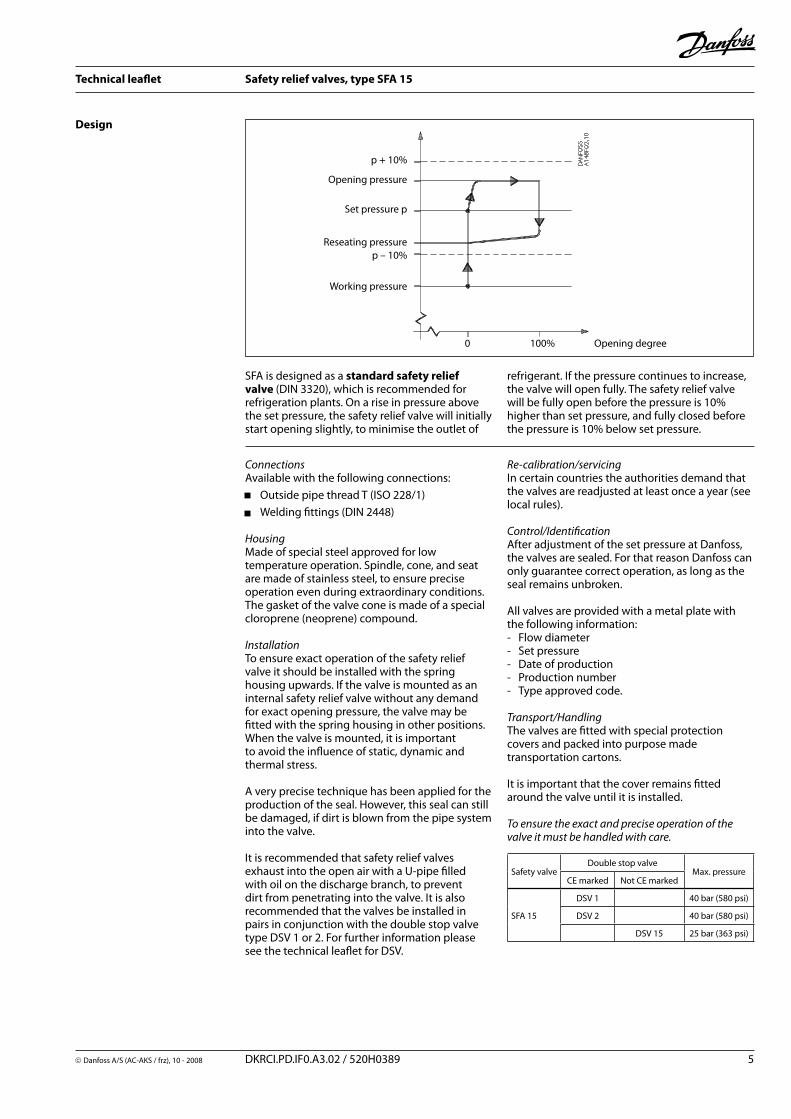
SFA is designed as a standard safety relief valve (DIN 3320), which is recommended for refrigeration plants. On a rise in pressure above the set pressure, the safety relief valve will initially start opening slightly, to minimise the outlet of
Re-calibration/servicingIn certain countries the authorities demand that the valves are readjusted at least once a year (see local rules).
Control/IdentificationAfter adjustment of the set pressure at Danfoss, the valves are sealed. For that reason Danfoss can only guarantee correct operation, as long as the seal remains unbroken.
All valves are provided with a metal plate with the following information: - Flow diameter- Set pressure- Date of production- Production number- Type approved code.
Transport/HandlingThe valves are fitted with special protection covers and packed into purpose made transportation cartons.
It is important that the cover remains fitted around the valve until it is installed.
To ensure the exact and precise operation of the valve it must be handled with care.
refrigerant. If the pressure continues to increase, the valve will open fully. The safety relief valve will be fully open before the pressure is 10% higher than set pressure, and fully closed before the pressure is 10% below set pressure.
Working pressure
Reseating pressure
Set pressure p
Opening pressure
p + 10%
p – 10%
0 100% Opening degree
Safety valveDouble stop valve
Max. pressureCE marked Not CE marked
SFA 15
DSV 1 40 bar (580 psi)
DSV 2 40 bar (580 psi)
DSV 15 25 bar (363 psi)
6 DKRCI.PD.IF0.A3.02 / 520H0389 Danfoss A/S (AC-AKS / frz), 10 - 2008
Technical leaflet Safety relief valves, type SFA 15
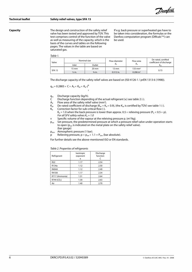
Capacity The design and construction of the safety relief valve has been tested and approved by TÜV. This test comprises control of the function of the valve as well as measuring of the capacity, which is the basis of the curves and tables on the following pages. The values in the table are based on saturated gas.
If e.g. back pressure or superheated gas have to be taken into consideration, the formulas or the Danfoss computation program (DIRcalc) can be used.
qm Discharge capacity (kg/h).C Discharge function depending of the actual refrigerant (κ) see table 2 (-).A0 Flow area of the safety relief valve (mm2).Kdr De-rated coefficient of discharge (Kdr = Kd × 0.9), (the Kdr is certified by TÜV) see table 1 (-).Kb Correction factor for sub-critical flow (-). Kb = 1.0 when the back pressure is lower than approx. 0.5 × relieving pressure (Pb < 0.5 × p). For all SFV safety valves Kb = 1.0v Specific volume of the vapour at the releiving pressure p. (m3/kg).pset Set pressure, the predetermined pressure at which a pressure relief valve under operation starts to open (pset is indicated on the metal plate on the safety relief valve). (bar gauge)patm Atmospheric pressure (1 bar).p Relieving pressure, p = pset × 1.1 + Patm (bar absolute).
For further details see the above-mentioned ISO or EN standards.
Table 1.
Table 2. Properties of refrigerants
RefrigerantIsentropic exponent
κ
Dischargefunction
C
R22 1.17 2.54
R134a 1.12 2.50
R404A 1.12 2.49
R410A 1.17 2.54
R717 (Ammonia) 1.31 2.64
R744 (CO2) 1.30 2.63
Air 1.40 2.70
ValveNominal size Flow diameter
do
Flow areaA0
De-rated, certified coefficient of discharge
KdrInlet Outlet
SFA 1515 mm 20 mm 13 mm 133 mm2
0.73½ in. ¾ in. 0.512 in. 0.206 in2
The discharge capacity of the safety relief valves are based on (IS0 4126-1 / prEN 1313 6 (1998)).
qm = 0.2883 × C × A0 × Kdr × Kb √p
v
Danfoss A/S (AC-AKS / frz), 10 - 2008 DKRCI.PD.IF0.A3.02 / 520H0389 7
Technical leaflet Safety relief valves, type SFA 15
Capacity
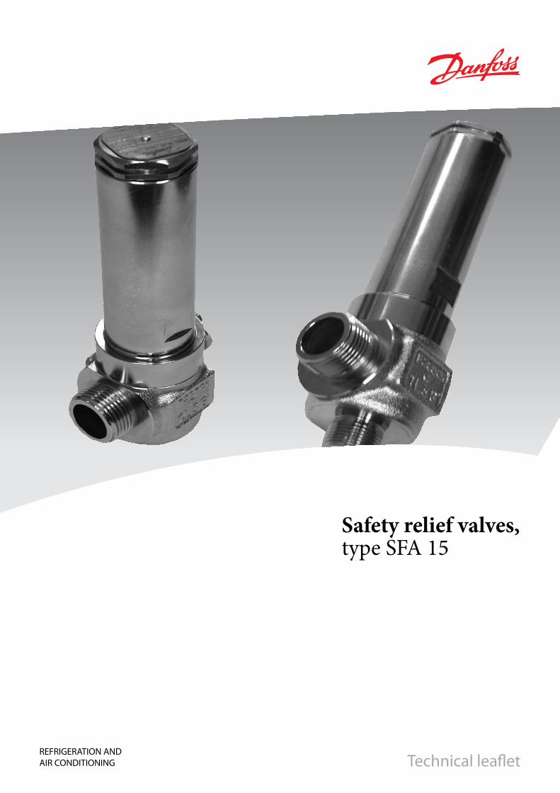
Capacity
SFA 15Set pressure
Capacity
R717
R404A R134a
Air (20°C)
R22R410A
R744 (CO2)
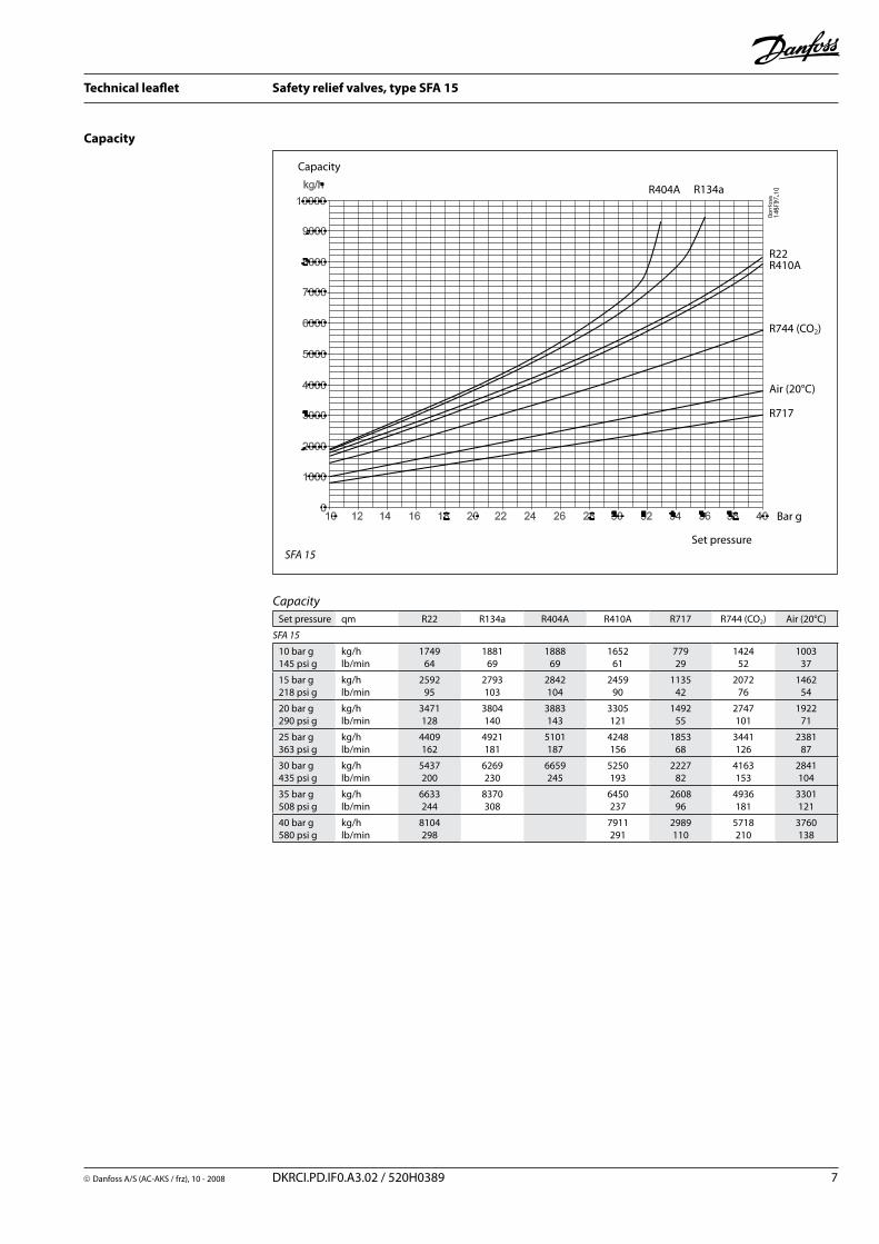
Set pressure qm R22 R134a R404A R410A R717 R744 (CO2) Air (20°C)
SFA 15
10 bar g145 psi g
kg/hlb/min
174964
188169
188869
165261
77929
142452
100337
15 bar g218 psi g
kg/hlb/min
259295
2793103
2842104
245990
113542
207276
146254
20 bar g290 psi g
kg/hlb/min
3471128
3804140
3883143
3305121
149255
2747101
192271
25 bar g363 psi g
kg/hlb/min
4409162
4921181
5101187
4248156
185368
3441126
238187
30 bar g435 psi g
kg/hlb/min
5437200
6269230
6659245
5250193
222782
4163153
2841104
35 bar g508 psi g
kg/hlb/min
6633244
8370308
6450237
260896
4936181
3301121
40 bar g580 psi g
kg/hlb/min
8104298
7911291
2989110
5718210
3760138
Bar g
8 DKRCI.PD.IF0.A3.02 / 520H0389 Danfoss A/S (AC-AKS / frz), 10 - 2008
Technical leaflet Safety relief valves, type SFA 15
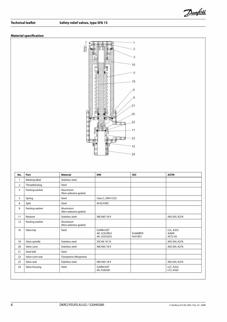
Material specification
No. Part Material DIN ISO ASTM
1 Marking label Stainless steel
2 Threaded plug Steel
3 Packing washer Aluminium(Non-asbestos gasket)
5 Spring Steel Class C, DIN17223
8 Split Steel 94 ELFORZ
9 Packing washer Aluminium(Non-asbestos gasket)
11 Retainer Stainless steel X8CrNiS 18 9 AISI 303, A276
12 Packing washer Aluminium(Non-asbestos gasket)
16 Valve top Steel G20Mn5QTAlt. S235JRG2Alt. S355J2G3
Fe360BFNFe510D1
LCC, A352A284CA572-50
18 Valve spindle Stainless steel X5CrNi 18 10 AISI 304, A276
20 Valve cone Stainless steel X8CrNiS 18 9 AISI 303, A276
21 Steel ball Steel
22 Valve cone seal Cloroprene (Neoprene)
23 Valve seat Stainless steel X8CrNiS 18 9 AISI 303, A276
24 Valve housing Steel G20Mn5QTAlt. P285QH
LCC, A352LF2, A350
Danfoss A/S (AC-AKS / frz), 10 - 2008 DKRCI.PD.IF0.A3.02 / 520H0389 9
Technical leaflet Safety relief valves, type SFA 15
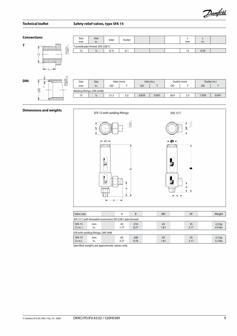
Connections
T
DIN Size Size Inlet (mm) Inlet (in.) Outlet (mm) Outlet (in.)
mm in. OD T OD T OD T OD T
Welding fittings, DIN (2448)
15 ½ 21.3 2.3 0.839 0.091 26.9 2.3 1.059 0.091
Dimensions and weightsSFA 15 T
Sizemm
Sizein.
Inlet OutletL
mmL
in.
T outside pipe thread, (ISO 228/1)
15 ½ G ¾ G 1 15 0.59
Specified weights are approximate values only.
Valve size A B ØD AF Weight
SFA 15 T, with threaded connections ISO 228/1 pipe threads
SFA 15 (½ in. )
mmin.
451.77
2108.27
451.81
552.17
2.2 kg4.9 lbs
SFA with welding fittings, DIN 2448
SFA 15 (½ in.)
mmin.
833.27
2489.76
451.81
552.17
2.5 kg5.5 lbs
SFA 15 with welding fittings
10 DKRCI.PD.IF0.A3.02 / 520H0389 Danfoss A/S (AC-AKS / frz), 10 - 2008
Technical leaflet Safety relief valves, type SFA 15
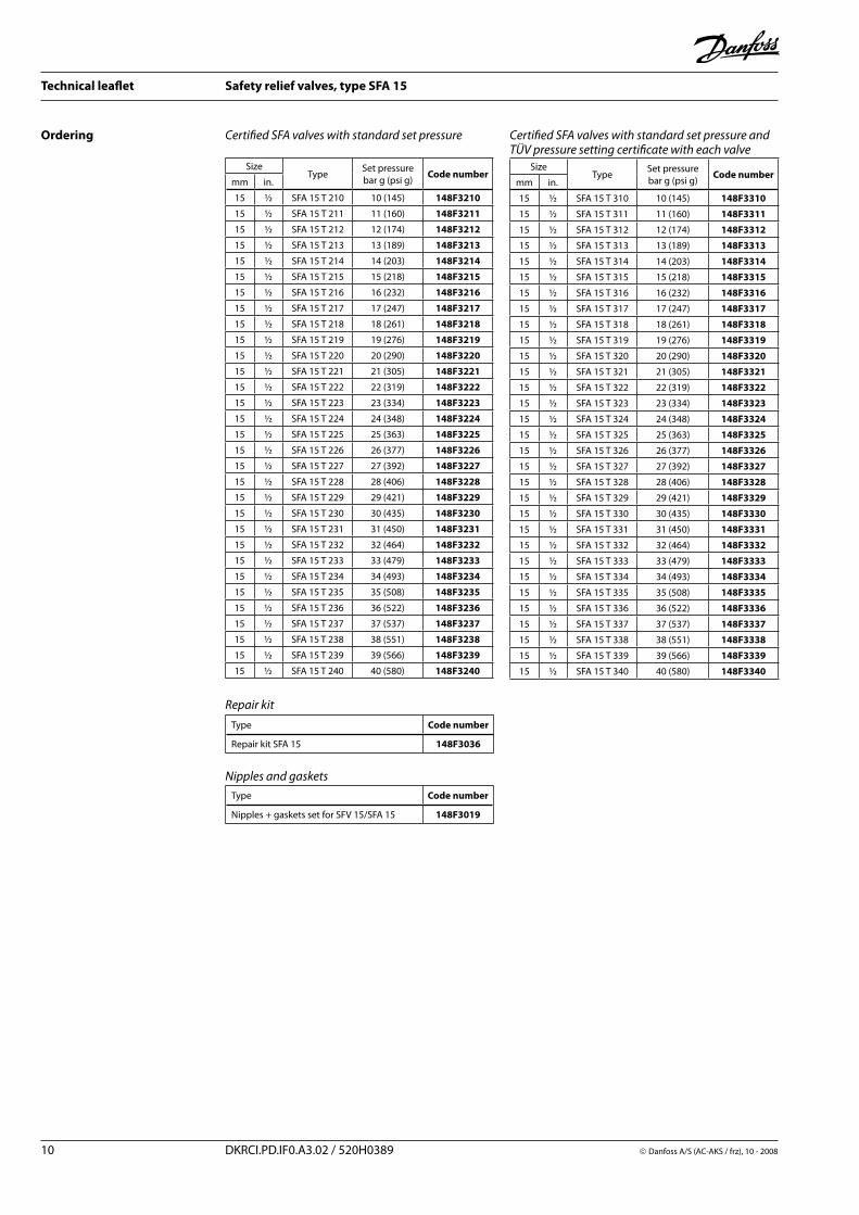
Certified SFA valves with standard set pressure
SizeType
Set pressurebar g (psi g)
Code numbermm in.
15 ½ SFA 15 T 210 10 (145) 148F3210
15 ½ SFA 15 T 211 11 (160) 148F3211
15 ½ SFA 15 T 212 12 (174) 148F3212
15 ½ SFA 15 T 213 13 (189) 148F3213
15 ½ SFA 15 T 214 14 (203) 148F3214
15 ½ SFA 15 T 215 15 (218) 148F3215
15 ½ SFA 15 T 216 16 (232) 148F3216
15 ½ SFA 15 T 217 17 (247) 148F3217
15 ½ SFA 15 T 218 18 (261) 148F3218
15 ½ SFA 15 T 219 19 (276) 148F3219
15 ½ SFA 15 T 220 20 (290) 148F3220
15 ½ SFA 15 T 221 21 (305) 148F3221
15 ½ SFA 15 T 222 22 (319) 148F3222
15 ½ SFA 15 T 223 23 (334) 148F3223
15 ½ SFA 15 T 224 24 (348) 148F3224
15 ½ SFA 15 T 225 25 (363) 148F3225
15 ½ SFA 15 T 226 26 (377) 148F3226
15 ½ SFA 15 T 227 27 (392) 148F3227
15 ½ SFA 15 T 228 28 (406) 148F3228
15 ½ SFA 15 T 229 29 (421) 148F3229
15 ½ SFA 15 T 230 30 (435) 148F3230
15 ½ SFA 15 T 231 31 (450) 148F3231
15 ½ SFA 15 T 232 32 (464) 148F3232
15 ½ SFA 15 T 233 33 (479) 148F3233
15 ½ SFA 15 T 234 34 (493) 148F3234
15 ½ SFA 15 T 235 35 (508) 148F3235
15 ½ SFA 15 T 236 36 (522) 148F3236
15 ½ SFA 15 T 237 37 (537) 148F3237
15 ½ SFA 15 T 238 38 (551) 148F3238
15 ½ SFA 15 T 239 39 (566) 148F3239
15 ½ SFA 15 T 240 40 (580) 148F3240
Ordering Certified SFA valves with standard set pressure and TÜV pressure setting certificate with each valve
SizeType
Set pressurebar g (psi g)
Code numbermm in.
15 ½ SFA 15 T 310 10 (145) 148F3310
15 ½ SFA 15 T 311 11 (160) 148F3311
15 ½ SFA 15 T 312 12 (174) 148F3312
15 ½ SFA 15 T 313 13 (189) 148F3313
15 ½ SFA 15 T 314 14 (203) 148F3314
15 ½ SFA 15 T 315 15 (218) 148F3315
15 ½ SFA 15 T 316 16 (232) 148F3316
15 ½ SFA 15 T 317 17 (247) 148F3317
15 ½ SFA 15 T 318 18 (261) 148F3318
15 ½ SFA 15 T 319 19 (276) 148F3319
15 ½ SFA 15 T 320 20 (290) 148F3320
15 ½ SFA 15 T 321 21 (305) 148F3321
15 ½ SFA 15 T 322 22 (319) 148F3322
15 ½ SFA 15 T 323 23 (334) 148F3323
15 ½ SFA 15 T 324 24 (348) 148F3324
15 ½ SFA 15 T 325 25 (363) 148F3325
15 ½ SFA 15 T 326 26 (377) 148F3326
15 ½ SFA 15 T 327 27 (392) 148F3327
15 ½ SFA 15 T 328 28 (406) 148F3328
15 ½ SFA 15 T 329 29 (421) 148F3329
15 ½ SFA 15 T 330 30 (435) 148F3330
15 ½ SFA 15 T 331 31 (450) 148F3331
15 ½ SFA 15 T 332 32 (464) 148F3332
15 ½ SFA 15 T 333 33 (479) 148F3333
15 ½ SFA 15 T 334 34 (493) 148F3334
15 ½ SFA 15 T 335 35 (508) 148F3335
15 ½ SFA 15 T 336 36 (522) 148F3336
15 ½ SFA 15 T 337 37 (537) 148F3337
15 ½ SFA 15 T 338 38 (551) 148F3338
15 ½ SFA 15 T 339 39 (566) 148F3339
15 ½ SFA 15 T 340 40 (580) 148F3340
Type Code number
Repair kit SFA 15 148F3036
Nipples and gaskets
Type Code number
Nipples + gaskets set for SFV 15/SFA 15 148F3019
Repair kit
Danfoss A/S (AC-AKS / frz), 10 - 2008 DKRCI.PD.IF0.A3.02 / 520H0389 11
Technical leaflet Safety relief valves, type SFA 15
12 DKRCI.PD.IF0.A3.02 / 520H0389 Danfoss A/S (AC-AKS / frz), 10 - 2008
Technical leaflet Safety relief valves, type SFA 15