Embed Size (px)
Citation preview
Back Pressure andRelief Valves
BULLETIN BP-08
Back Pressure andRelief Valves
Purpose
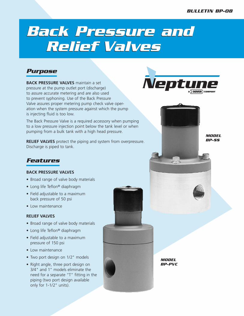
BACK PRESSURE VALVES maintain a setpressure at the pump outlet port (discharge)to assure accurate metering and are also usedto prevent syphoning. Use of the Back PressureValve assures proper metering pump check valve oper-ation when the system pressure against which the pumpis injecting fluid is too low.
The Back Pressure Valve is a required accessory when pumpingto a low pressure injection point below the tank level or whenpumping from a bulk tank with a high head pressure.
RELIEF VALVES protect the piping and system from overpressure.Discharge is piped to tank.
Features
BACK PRESSURE VALVES
• Broad range of valve body materials
• Long life Teflon® diaphragm
• Field adjustable to a maximumback pressure of 50 psi
• Low maintenance
RELIEF VALVES
• Broad range of valve body materials
• Long life Teflon® diaphragm
• Field adjustable to a maximumpressure of 150 psi
• Low maintenance
• Two port design on 1/2" models
• Right angle, three port design on3/4" and 1" models eliminate theneed for a separate “T” fitting in thepiping (two port design availableonly for 1-1/2" units).
MODELBP-SS
MODELBP-PVC
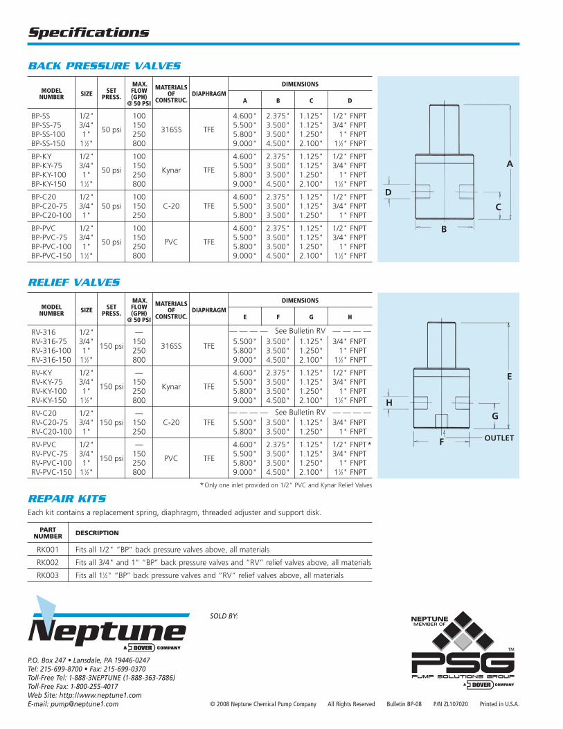
Specifications
.MAX. MATERIALS DIMENSIONSMODEL SIZE SET FLOW OF DIAPHRAGMNUMBER PRESS. (GPH) CONSTRUC. A B C D@ 50 PSI
BP-SS 1/2" 100 4.600" 2.375" 1.125" 1/2" FNPTBP-SS-75 3/4"
50 psi150
316SS TFE5.500" 3.500" 1.125" 3/4" FNPT
BP-SS-100 1" 250 5.800" 3.500" 1.250" 1" FNPTBP-SS-150 11⁄2" 800 9.000" 4.500" 2.100" 11⁄2" FNPT
BP-KY 1/2" 100 4.600" 2.375" 1.125" 1/2" FNPTBP-KY-75 3/4"
50 psi150
Kynar TFE5.500" 3.500" 1.125" 3/4" FNPT
BP-KY-100 1" 250 5.800" 3.500" 1.250" 1" FNPTBP-KY-150 11⁄2" 800 9.000" 4.500" 2.100" 11⁄2" FNPT
BP-C20 1/2" 100 4.600" 2.375" 1.125" 1/2" FNPTBP-C20-75 3/4" 50 psi 150 C-20 TFE 5.500" 3.500" 1.125" 3/4" FNPTBP-C20-100 1" 250 5.800" 3.500" 1.250" 1" FNPT
BP-PVC 1/2" 100 4.600" 2.375" 1.125" 1/2" FNPTBP-PVC-75 3/4"
50 psi150
PVC TFE5.500" 3.500" 1.125" 3/4" FNPT
BP-PVC-100 1" 250 5.800" 3.500" 1.250" 1" FNPTBP-PVC-150 11⁄2" 800 9.000" 4.500" 2.100" 11⁄2" FNPT
BACK PRESSURE VALVES
PARTNUMBER DESCRIPTION
RK001 Fits all 1/2" “BP” back pressure valves above, all materials
RK002 Fits all 3/4" and 1" “BP” back pressure valves and “RV” relief valves above, all materials
RK003 Fits all 11⁄2" “BP” back pressure valves and “RV” relief valves above, all materials
REPAIR KITSEach kit contains a replacement spring, diaphragm, threaded adjuster and support disk.
.MAX. MATERIALS DIMENSIONSMODEL SIZE SET FLOW OF DIAPHRAGMNUMBER PRESS. (GPH) CONSTRUC. E F G H@ 50 PSI
RV-316 1/2" —RV-316-75 3/4"
150 psi150
316SS TFE5.500" 3.500" 1.125" 3/4" FNPT
RV-316-100 1" 250 5.800" 3.500" 1.250" 1" FNPTRV-316-150 11⁄2" 800 9.000" 4.500" 2.100" 11⁄2" FNPT
RV-KY 1/2" — 4.600" 2.375" 1.125" 1/2" FNPTRV-KY-75 3/4"
150 psi150
Kynar TFE5.500" 3.500" 1.125" 3/4" FNPT
RV-KY-100 1" 250 5.800" 3.500" 1.250" 1" FNPTRV-KY-150 11⁄2" 800 9.000" 4.500" 2.100" 11⁄2" FNPT
RV-C20 1/2" —RV-C20-75 3/4" 150 psi 150 C-20 TFE 5.500" 3.500" 1.125" 3/4" FNPTRV-C20-100 1" 250 5.800" 3.500" 1.250" 1" FNPT
RV-PVC 1/2" — 4.600" 2.375" 1.125" 1/2" FNPT*RV-PVC-75 3/4"
150 psi150
PVC TFE5.500" 3.500" 1.125" 3/4" FNPT
RV-PVC-100 1" 250 5.800" 3.500" 1.250" 1" FNPTRV-PVC-150 11⁄2" 800 9.000" 4.500" 2.100" 11⁄2" FNPT
*Only one inlet provided on 1/2" PVC and Kynar Relief Valves
RELIEF VALVES
— — — — See Bulletin RV — — — —
— — — — See Bulletin RV — — — —
A
H
F
G
E
OUTLET
C
B
D
© 2008 Neptune Chemical Pump Company All Rights Reserved Bulletin BP-08 P/N ZL107020 Printed in U.S.A.
SOLD BY:
P.O. Box 247 • Lansdale, PA 19446-0247Tel: 215-699-8700 • Fax: 215-699-0370Toll-Free Tel: 1-888-3NEPTUNE (1-888-363-7886)Toll-Free Fax: 1-800-255-4017Web Site: http://www.neptune1.comE-mail: [email protected]
Relief Valves
BULLETIN RV-08
Relief ValvesFeatures
• All wetted parts are 316SS or Carpenter 20
• Pressures from 30 to 2000 psi
• Spring guide for consistent relief capacity
• Easily adjustable relief setting
• Liquid service only
Neptune Relief Valves have two outstanding characteristics:• economy • simplicity
Economy. Models RV-316-1, -2, -3 and -4 with all 316SS wettedparts cost no more than other 304SS designs. Carpenter 20 valvesare also available as standard.
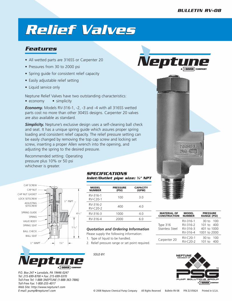
Simplicity. Neptune’s exclusive design uses a self-cleaning ball checkand seat. It has a unique spring guide which assures proper springloading and consistent relief capacity. The relief pressure setting canbe easily changed by removing the top cap screw and locking setscrew, inserting a proper Allen wrench into the opening, andadjusting the spring to the desired pressure.
Recommended setting: Operatingpressure plus 10% or 50 psiwhichever is greater.
CAP SCREW
CAP NUT
CAP NUT GASKET
LOCK SETSCREW
ADJUSTINGSETSCREW
SPRING GUIDE
SPRING
VALVE BODY
SPRING SEAT
BALL CHECK
BALL SEAT
© 2008 Neptune Chemical Pump Company All Rights Reserved Bulletin RV-08 P/N ZL105624 Printed in U.S.A.
SOLD BY:
Quotation and Ordering InformationPlease supply the following information:
1. Type of liquid to be handled.
2. Relief pressure range or set point required.
MATERIAL OF MODEL PRESSURECONSTRUCTION NUMBER RANGE (PSI)
RV-316-1 30 to 100Type 316 RV-316-2 101 to 400Stainless Steel RV-316-3 401 to 1000
RV-316-4 1001 to 2000
Carpenter 20RV-C20-1 30 to 100RV-C20-2 101 to 400
SPECIFICATIONSInlet/Outlet pipe size: 1⁄2" NPT
MODEL PRESSURE CAPACITYNUMBER (PSI) (GPM)
RV-316-1100 3.0
RV-C20-1
RV-316-2400 4.0
RV-C20-2
RV-316-3 1000 4.0
RV-316-4 2000 6.0
1⁄2" FNPT
1⁄2" MNPT
43⁄16"
113⁄16"
11⁄8"
P.O. Box 247 • Lansdale, PA 19446-0247Tel: 215-699-8700 • Fax: 215-699-0370Toll-Free Tel: 1-888-3NEPTUNE (1-888-363-7886)Toll-Free Fax: 1-800-255-4017Web Site: http://www.neptune1.comE-mail: [email protected]