Embed Size (px)
Citation preview
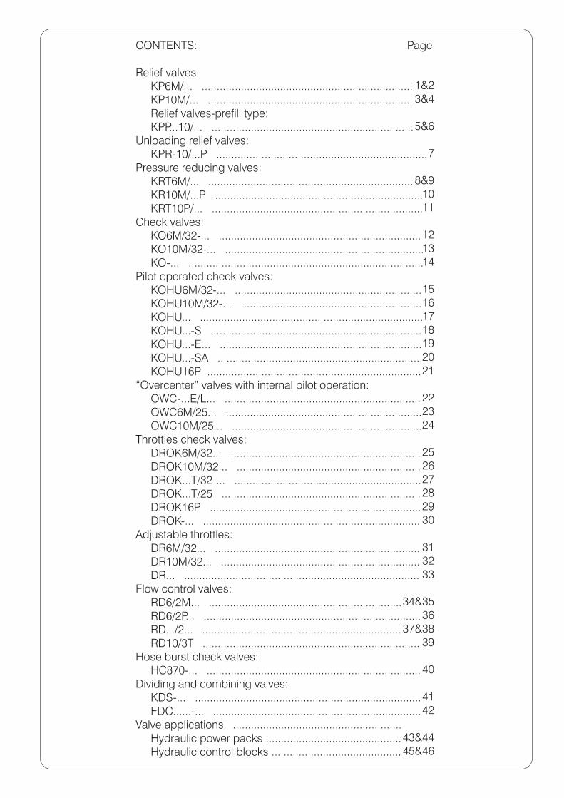
CONTENTS:
Relief valves: KP6M/... ...................................................................... KP10M/... .................................................................... Relief valves-prefill type: KPP...10/... ...................................................................Unloading relief valves: KPR-10/...P ......................................................................Pressure reducing valves: KRT6M/... .................................................................... KR10M/...P ..................................................................... KRT10P/... ......................................................................Check valves: KO6M/32-... ................................................................... KO10M/32-... .................................................................. KO-... ..............................................................................Pilot operated check valves: KOHU6M/32-... .............................................................. KOHU10M/32-... ............................................................ KOHU... .......................................................................... KOHU...-S ...................................................................... KOHU...-E... ................................................................... KOHU...-SA .................................................................... KOHU16P .......................................................................“Overcenter” valves with internal pilot operation: OWC-...E/L... ................................................................. OWC6M/25... ................................................................. OWC10M/25... ...............................................................Throttles check valves: DROK6M/32... ............................................................... DROK10M/32... ............................................................. DROK...T/32-... .............................................................. DROK...T/25 .................................................................. DROK16P ...................................................................... DROK-... ........................................................................Adjustable throttles: DR6M/32... .................................................................... DR10M/32... .................................................................. DR... ..............................................................................Flow control valves: RD6/2M... ................................................................ RD6/2P... ........................................................................ RD.../2... .................................................................. RD10/3T ........................................................................Hose burst check valves: HC870-... .......................................................................Dividing and combining valves: KDS-... ........................................................................... FDC......-... .....................................................................Valve applications ........................................................ Hydraulic power packs ............................................. Hydraulic control blocks ...........................................
Page
1&2 3&4
5&6
7
8&9 10 11
12 13 14
15 16 17 18 19 20
21
22 23
24
25 26 27 28
2930
31 32 33
34&35 36
37&38 39
40
4142
43&4445&46
1
DESCRIPTION DIMENSIONS
RELIEF VALVES
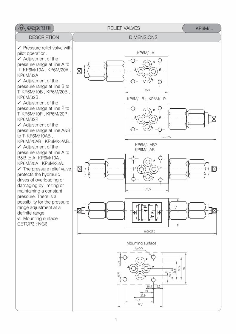
Pressure relief valve withpilot operation.
Adjustment of the pressure range at line A to T: KP6M/10A , KP6M/20A ,KP6M/32A.
Adjustment of the pressure range at line B to T: KP6M/10B , KP6M/20B ,KP6M/32B.
Adjustment of thepressure range at line P to T: KP6M/10P , KP6M/20P ,KP6M/32P.
Adjustment of the pressure range at line A&B to T: KP6M/10AB , KP6M/20AB , KP6M/32AB.
Adjustment of the pressure range at line A to B&B to A: KP6M/10A , KP6M/20A , KP6M/32A.
The pressure relief valveprotects the hydraulic drives of overloading or damaging by limiting or maintaining a constant pressure. There is a possibility for the pressure range adjustment at a definite range.
Mounting surface CETOP3 ; NG6
KP6M/...AB2
Mounting surface
KP6M/...AB
KP6M/...B ; KP6M/...P
KP6M/...A
KP6M/...
2
RELIEF VALVES KP6M/...
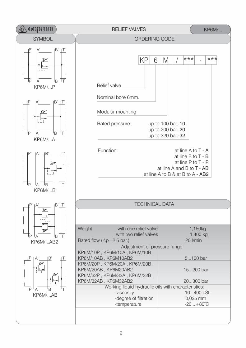
Weight with one relief valve 1,150kg with two relief valves 1,400 kg
Rated flow (Dp=2,5 bar.) 20 l/min
Adjustment of pressure range:KP6M/10P , KP6M/10A , KP6M/10B ,KP6M/10AB , KP6M10AB2 5...100 barKP6M/20P , KP6M/20A , KP6M/20B ,KP6M/20AB , KP6M20AB2 15...200 barKP6M/32P , KP6M/32A , KP6M/32B ,KP6M/32AB , KP6M32AB2 20...300 bar Working liquid-hydraulic oils with characteristics: -viscosity 10...400 cSt -degree of filtration 0,025 mm
o -temperature -20...+80 C
KP6M/...PA T
A’ T’
KP6M/...A
P A B T
P’ A’ B’ T’
P A B T
P’ A’ B’ T’
KP6M/...B
KP6M/...AB2
P A B T
P’ A’ B’ T’
P A B T
P’ A’ B’ T’
KP6M/...ABP A B T
P’ A’ B’ T’
TECHNICAL DATA
ORDERING CODE
KP 6 M / *** - ***
Relief valve
Modular mounting
Function: at line A to T - A at line B to T - B at line P to T - P
at line A and B to T - AB at line A to B & at B to A - AB2
Rated pressure: up to 100 bar.-10 up to 200 bar.-20 up to 320 bar.-32
Nominal bore 6mm.
SYMBOL ORDERING CODE
3
DESCRIPTION DIMENSIONS
RELIEF VALVES
Mounting surface
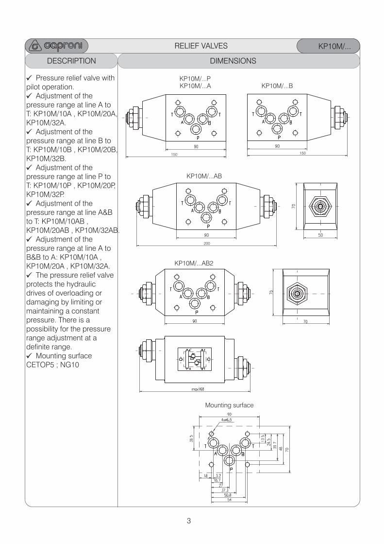
KP10M/...PKP10M/...A
KP10M/...
KP10M/...B
KP10M/...AB
150 150
200
KP10M/...AB2
Pressure relief valve withpilot operation.
Adjustment of the pressure range at line A toT: KP10M/10A , KP10M/20A,KP10M/32A.
Adjustment of the pressure range at line B to T: KP10M/10B , KP10M/20B,KP10M/32B.
Adjustment of thepressure range at line P to T: KP10M/10P , KP10M/20P,KP10M/32P.
Adjustment of the pressure range at line A&B to T: KP10M/10AB , KP10M/20AB , KP10M/32AB.
Adjustment of the pressure range at line A to B&B to A: KP10M/10A , KP10M/20A , KP10M/32A.
The pressure relief valveprotects the hydraulic drives of overloading or damaging by limiting or maintaining a constant pressure. There is a possibility for the pressure range adjustment at a definite range.
Mounting surface CETOP5 ; NG10

4
RELIEF VALVES KP10M/...
Weight with one relief valve 2,700kg with two relief valves 3,050 kg
Rated flow (Dp=2,5 bar.) 40 l/min
Adjustment of pressure range:KP10M/10P , KP10M/10A , KP10M/10B ,KP10M/10AB , KP10M10AB2 5...100 barKP10M/20P , KP10M/20A , KP10M/20B ,KP10M/20AB , KP10M20AB2 15...200 barKP10M/32P , KP10M/32A , KP10M/32B ,KP10M/32AB , KP10M32AB2 20...320 bar Working liquid-hydraulic oils with characteristics: -viscosity 10...400 cSt -degree of filtration 0,025 mm
o -temperature -20...+80 C
KP10M/...P
A’
KP10M/...A
P A B T
P’ A’ B’ T’
P A B T
P’ A’ B’ T’
KP10M/...B
KP10M/...AB2
P A B T
P’ A’ B’ T’
P A B T
P’ A’ B’ T’
KP10M/...ABP A B T
P’ A’ B’ T’
TECHNICAL DATA
ORDERING CODE
KP 10 M / *** - ***
Relief valve
Modular mounting
Function: at line A to T - A at line B to T - B at line P to T - P
at line A and B to T - AB at line A to B & at B to A - AB2
Rated pressure: up to 100 bar.-10 up to 200 bar.-20 up to 320 bar.-32
Nominal bore 10mm.
SYMBOL ORDERING CODE
5
DESCRIPTION DIMENSIONS
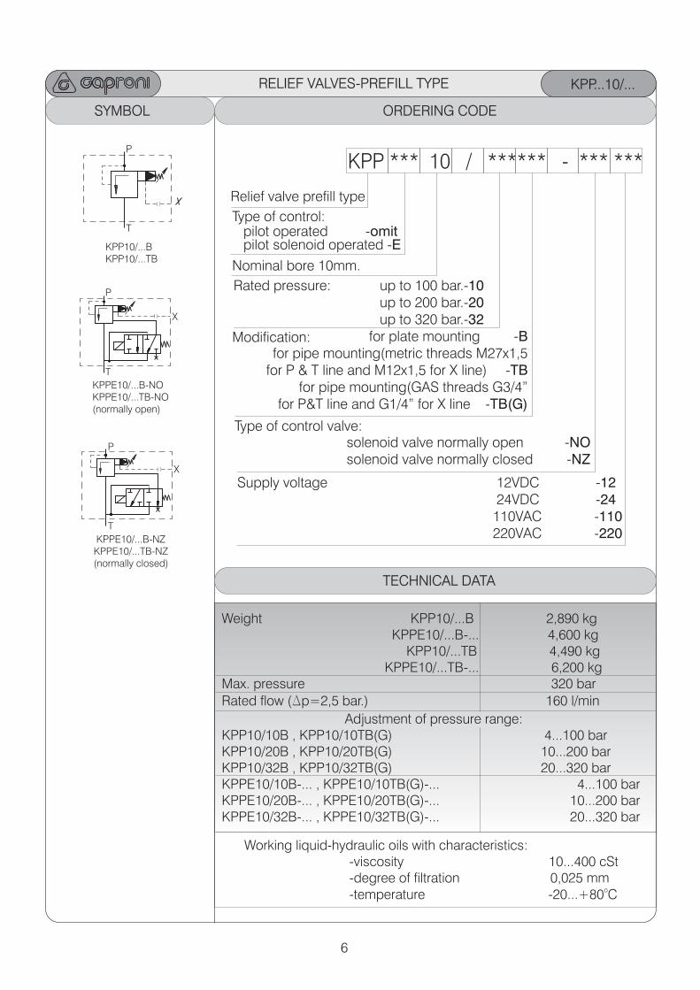
RELIEF VALVES-PREFILL TYPE
Mounting surface
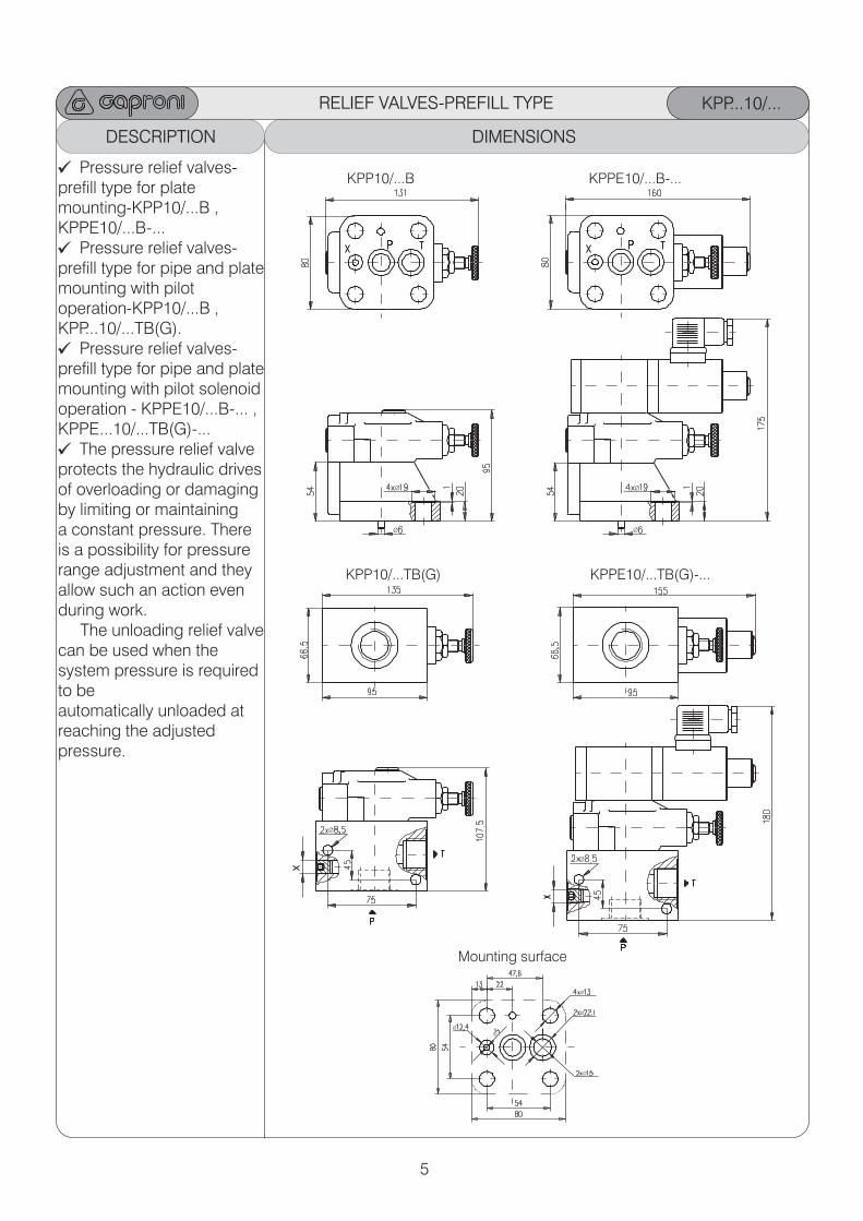
KPP10/...B
KPP...10/...
KPPE10/...B-...
KPP10/...TB(G) KPPE10/...TB(G)-...
Pressure relief valves-prefill type for plate mounting-KPP10/...B ,KPPE10/...B-...
Pressure relief valves-prefill type for pipe and plate mounting with pilot operation-KPP10/...B ,KPP...10/...TB(G).
Pressure relief valves-prefill type for pipe and plate mounting with pilot solenoid operation - KPPE10/...B-... ,KPPE...10/...TB(G)-...
The pressure relief valveprotects the hydraulic drivesof overloading or damaging by limiting or maintaining a constant pressure. There is a possibility for pressure range adjustment and they allow such an action even during work. The unloading relief valvecan be used when the system pressure is required to be automatically unloaded atreaching the adjusted pressure.
Ø
Ø
Ø
Ø
Ø
Ø
Ø
Ø
Ø
Ø
Ø
6
KPP...10/...
ORDERING CODE
KPP *** 10 / ****** - *** ***
Relief valve prefill type
Supply voltage 12VDC 24VDC -24 110VAC -110 220VAC -220
-12
Type of control:
Type of control valve:
Rated pressure: up to 100 bar.-10 up to 200 bar.-20 up to 320 bar.-32
Nominal bore 10mm.
SYMBOL ORDERING CODE
KPP10/...BKPP10/...TB
P
T
P
X
T
KPPE10/...B-NOKPPE10/...TB-NO(normally open)
X
P
T
KPPE10/...B-NZKPPE10/...TB-NZ(normally closed)
pilot solenoid operated -Epilot operated -omit
solenoid valve normally open -NOsolenoid valve normally closed -NZ
Modification: f for pipe mounting(metric threads M27x1,5
for P & T line and M12x1,5 for X line) -TB for pipe mounting(GAS threads G3/4”
for P&T line and G1/4” for X line -TB(G)
or plate mounting -B
Weight KPP10/...B 2,890 kg KPPE10/...B-... 4,600 kg KPP10/...TB 4,490 kg KPPE10/...TB-... 6,200 kgMax. pressure 320 bar
Rated flow (Dp=2,5 bar.) 160 l/min
Adjustment of pressure range:KPP10/10B , KPP10/10TB(G) 4...100 barKPP10/20B , KPP10/20TB(G) 10...200 barKPP10/32B , KPP10/32TB(G) 20...320 barKPPE10/10B-... , KPPE10/10TB(G)-... 4...100 barKPPE10/20B-... , KPPE10/20TB(G)-... 10...200 barKPPE10/32B-... , KPPE10/32TB(G)-... 20...320 bar
TECHNICAL DATA
RELIEF VALVES-PREFILL TYPE
Working liquid-hydraulic oils with characteristics: -viscosity 10...400 cSt -degree of filtration 0,025 mm
o -temperature -20...+80 C
7
DESCRIPTION DIMENSIONS
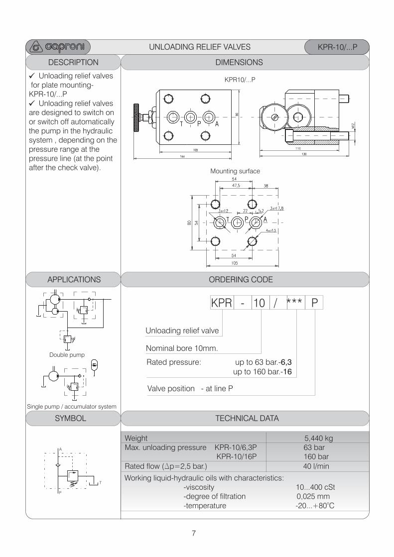
UNLOADING RELIEF VALVES
Mounting surface
KPR10/...P
Double pump
Single pump / accumulator system
KPR-10/...P
Unloading relief valves for plate mounting-KPR-10/...P
Unloading relief valvesare designed to switch onor switch off automaticallythe pump in the hydraulicsystem , depending on the pressure range at the pressure line (at the point after the check valve).
P
T
A
ORDERING CODEAPPLICATIONS
KPR - 10 / *** P
Unloading relief valve
Rated pressure: up to 63 bar.-6,3 up to 160 bar.-16
Nominal bore 10mm.
Valve position - at line P
TECHNICAL DATA
Weight 5,440 kg Max. unloading pressure KPR-10/6,3P 63 bar KPR-10/16P 160 bar
Rated flow (Dp=2,5 bar.) 40 l/min
SYMBOL
Working liquid-hydraulic oils with characteristics: -viscosity 10...400 cSt -degree of filtration 0,025 mm
o -temperature -20...+80 C
Ø
Ø
Ø
116
8
DESCRIPTION DIMENSIONS
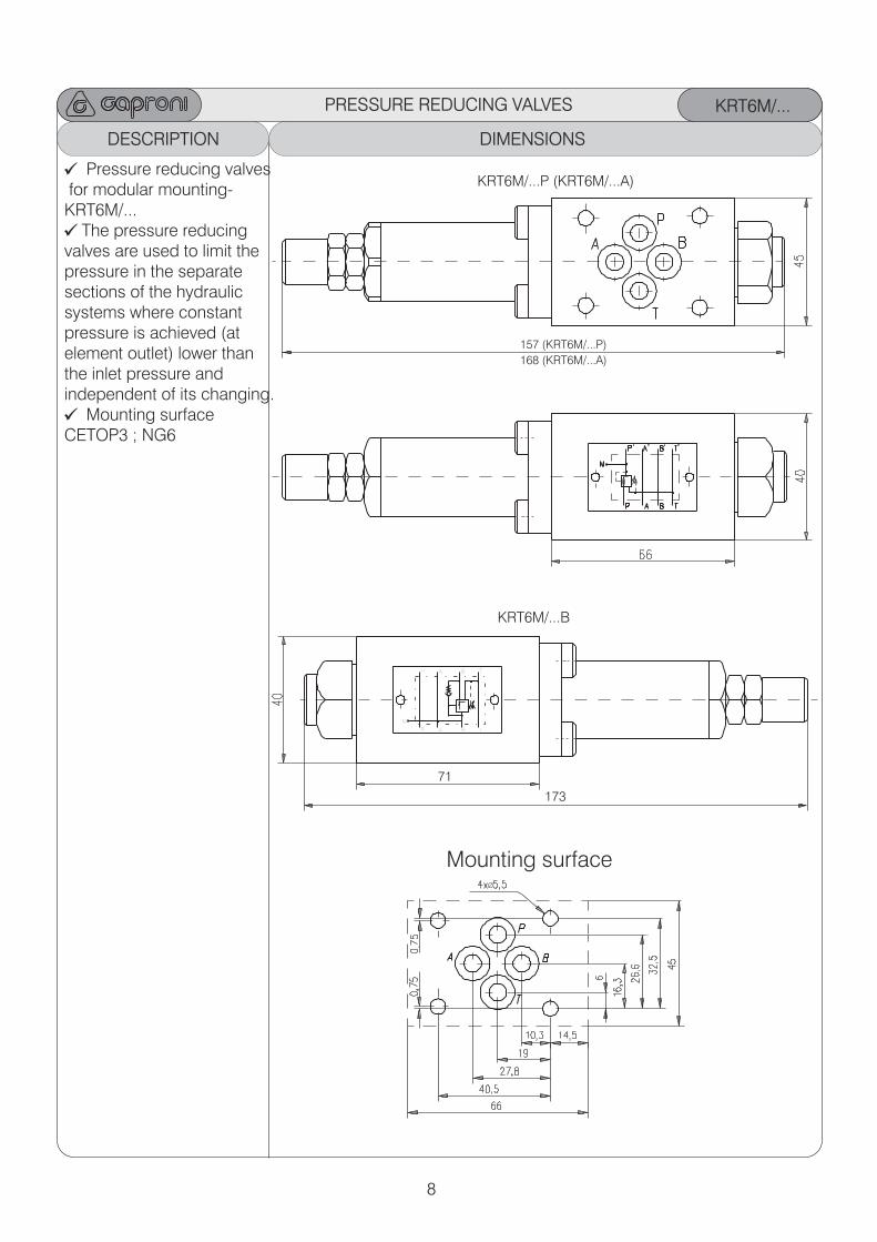
KRT6M/...
Pressure reducing valves for modular mounting-KRT6M/...
The pressure reducingvalves are used to limit thepressure in the separatesections of the hydraulicsystems where constantpressure is achieved (atelement outlet) lower thanthe inlet pressure andindependent of its changing.
Mounting surface CETOP3 ; NG6
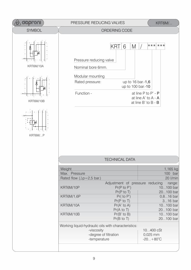
PRESSURE REDUCING VALVES
Mounting surfaceØ
P
M
A B T
P’ A’ B’ T’
KRT6M/...P ( )KRT6M/...A
KRT6M/...B
173
71
157 (KRT6M/...P)
168 (KRT6M/...A)
9
KRT6M/...
ORDERING CODE
KRT 6 M / *** ***
Pressure reducing valve
Rated pressure: up to 16 bar.-1,6 up to 100 bar.-10
Nominal bore 6mm.
TECHNICAL DATA
SYMBOL
Modular mounting
Function - at line P to P’ - P at line A’ to A - A at line B’ to B - B
Weight 1,165 kgMax. Pressure 100 bar
Rated flow (Dp=2,5 bar.) 20 l/min
Adjustment of pressure reducing range: KRT6M/10P Pr(P to P’) 10...100 bar Pr(P to T) 20...100 bar KRT6M/1,6P Pr( to P’) 0,8...16 bar Pr(P to T) 3...16 bar KRT6M/10A Pr(A’ to A) 10...100 bar Pr(A to T) 20...100 barKRT6M/10B Pr(B’ to B) 10...100 bar Pr(B to T) 20...100 bar
KRT6M/10A
KRT6M/10B
P
M
A B T
P’ A’ B’ T’
KRT6M/...P
P
M
A B T
P’ A’ B’ T’
PRESSURE REDUCING VALVES
Working liquid-hydraulic oils with characteristics: -viscosity 10...400 cSt -degree of filtration 0,025 mm
o -temperature -20...+80 C
P
M
A B T
P’ A’ B’ T’
10
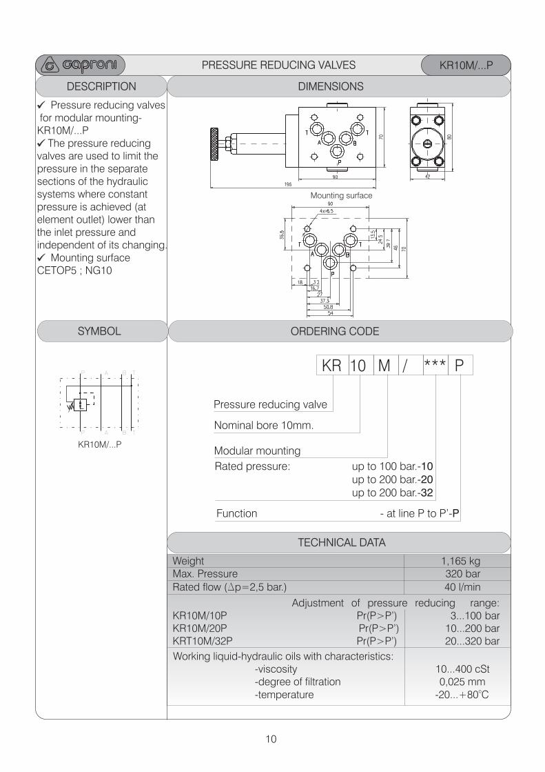
DESCRIPTION DIMENSIONS
Mounting surface
KR10M/...P
ORDERING CODE
KR 10 M / *** P
Pressure reducing valve
Rated pressure: up to 100 bar.-10 up to 200 bar.-20
up to 200 bar.-32
Nominal bore 10mm.
TECHNICAL DATA
SYMBOL
Pressure reducing valves for modular mounting-KR10M/...P
The pressure reducingvalves are used to limit thepressure in the separatesections of the hydraulicsystems where constantpressure is achieved (atelement outlet) lower thanthe inlet pressure andindependent of its changing.
Mounting surface CETOP5 ; NG10
Modular mounting
Function - at line P to P’-P
KR10M/...P
P A B T
P’ A’ B’ T’
Weight 1,165 kgMax. Pressure 320 bar
Rated flow (Dp=2,5 bar.) 40 l/min
Adjustment of pressure reducing range:KR10M/10P Pr(P>P’) 3...100 barKR10M/20P Pr(P>P’) 10...200 barKRT10M/32P Pr(P>P’) 20...320 bar
PRESSURE REDUCING VALVES
Working liquid-hydraulic oils with characteristics: -viscosity 10...400 cSt -degree of filtration 0,025 mm
o -temperature -20...+80 C
Ø
11
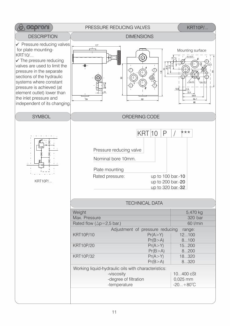
DESCRIPTION DIMENSIONS
PRESSURE REDUCING VALVES
Mounting surface
KRT10P/...
ORDERING CODE
KRT 10 P / ***
Pressure reducing valve
Rated pressure: up to 100 bar.-10 up to 200 bar.-20
up to 320 bar.-32
Nominal bore 10mm.
TECHNICAL DATA
SYMBOL
Pressure reducing valves for plate mounting-KRT10/...
The pressure reducingvalves are used to limit thepressure in the separatesections of the hydraulicsystems where constantpressure is achieved (atelement outlet) lower thanthe inlet pressure andindependent of its changing.
Plate mounting
KRT10P/...
X
AB
Y
Weight 5,470 kgMax. Pressure 320 bar
Rated flow (Dp=2,5 bar.) 60 l/min
Adjustment of pressure reducing range:KRT10P/10 Pr(A>Y) 12...100 Pr(B>A) 8...100 KRT10P/20 Pr(A>Y) 15...200 Pr(B>A) 8...200KRT10P/32 Pr(A>Y) 18...320 Pr(B>A) 8...320 Working liquid-hydraulic oils with characteristics: -viscosity 10...400 cSt -degree of filtration 0,025 mm
o -temperature -20...+80 C
Ø
Ø
ØØ
Ø
12
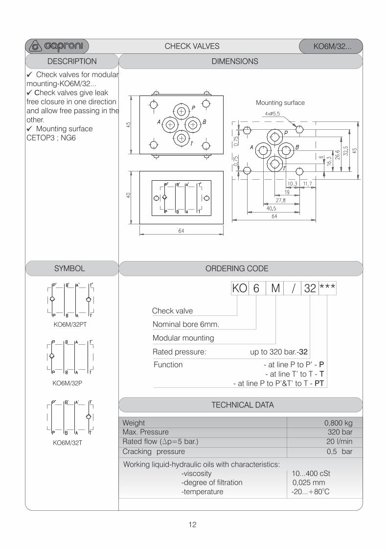
DESCRIPTION DIMENSIONS
CHECK VALVES KO6M/32...
ORDERING CODE
KO 6 M / 32 ***
Check valve
Rated pressure:
up to 320 bar.-32
Nominal bore 6mm.
TECHNICAL DATA
SYMBOL
Check valves for modular mounting-KO6M/32...
Check valves give leak free closure in one directionand allow free passing in the other.
Mounting surface CETOP3 ; NG6
Modular mounting
KO6M/32PT
KO6M/32T
KO6M/32P
Weight 0,800 kgMax. Pressure 320 bar
Rated flow (Dp=5 bar.) 20 l/min
Cracking pressure 0,5 bar
Mounting surface
Function - at line P to P’ - P - at line T’ to T - T
- at line P to P’&T’ to T - PT
Working liquid-hydraulic oils with characteristics: -viscosity 10...400 cSt -degree of filtration 0,025 mm
o -temperature -20...+80 C
13
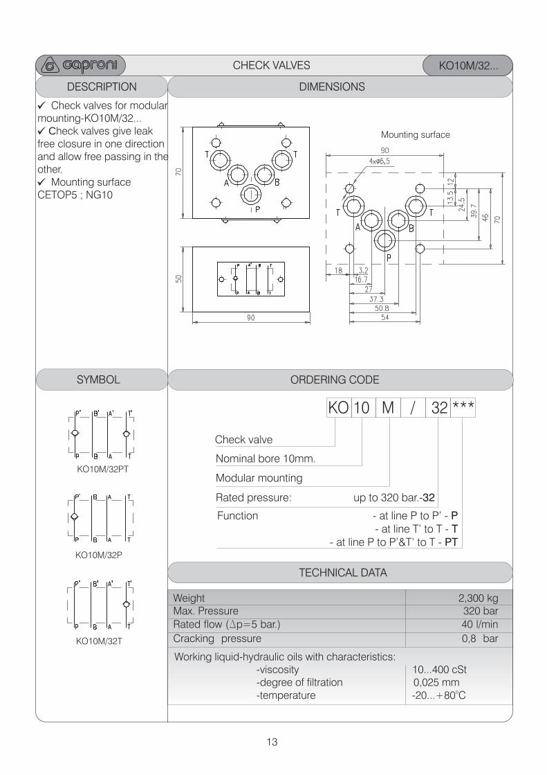
DESCRIPTION DIMENSIONS
CHECK VALVES KO10M/32...
ORDERING CODE
KO 10 M / 32 ***
Check valve
Rated pressure:
up to 320 bar.-32
Nominal bore 10mm.
TECHNICAL DATA
SYMBOL
Check valves for modular mounting-KO10M/32...
Check valves give leak free closure in one directionand allow free passing in the other.
Mounting surface CETOP5 ; NG10
Modular mountingKO10M/32PT
KO10M/32T
KO10M/32P
Weight 2,300 kgMax. Pressure 320 bar
Rated flow (Dp=5 bar.) 40 l/min
Cracking pressure 0,8 bar
Mounting surface
Function - at line P to P’ - P - at line T’ to T - T
- at line P to P’&T’ to T - PT
Working liquid-hydraulic oils with characteristics: -viscosity 10...400 cSt -degree of filtration 0,025 mm
o -temperature -20...+80 C
14
DESCRIPTION DIMENSIONS
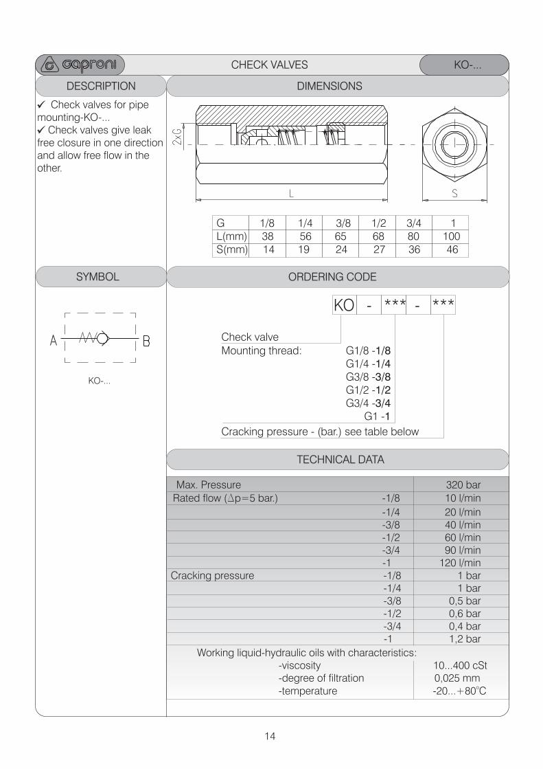
CHECK VALVES KO-...
ORDERING CODE
KO - *** - ***
Check valve
G 1/8 1/4 3/8 1 3/4 1 L(mm) 38 56 65 68 80 100 S(mm) 14 19 24 27 36 46
/2
Mounting thread: G1/8 G1/4 -1/4 G3/8 -3/8 G1/2 -1/2 G3/4 -3/4
G1 -1
-1/8
TECHNICAL DATA
SYMBOL
Check valves for pipe mounting-KO-...
Check valves give leak free closure in one directionand allow free flow in the other.
KO-...
Max. Pressure 320 bar
Rated flow (Dp=5 bar.) -1/8 10 l/min
-1/4 20 l/min -3/8 40 l/min -1/2 60 l/min
-3/4 90 l/min -1 120 l/min
Cracking pressure -1/8 1 bar -1/4 1 bar
-3/8 0,5 bar -1/2 0,6 bar
-3/4 0,4 bar -1 1,2 bar
Working liquid-hydraulic oils with characteristics: -viscosity 10...400 cSt -degree of filtration 0,025 mm
o -temperature -20...+80 C
Cracking pressure - (bar.) see table below
Ø
15
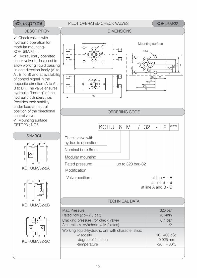
PILOT OPERATED CHECK VALVES KOHU6M/32-...
KOHU6M/32-2A
ORDERING CODE
KOHU 6 M / 32 - 2 ***
Check valve with hydraulic operation
Modular mounting
: at line A - A at line B - B
at line A and B - C
Valve position
Rated pressure: up to 320 bar.-32
Nominal bore 6mm.
DESCRIPTION ORDERING CODE
Modification
TECHNICAL DATA
Max. Pressure 320 bar
Rated flow (Dp=2,5 bar.) 20 l/min
Cracking pressure (for check valve) 0,7 barArea ratio A1/A2(check valve/piston) 1/2
Working liquid-hydraulic oils with characteristics: -viscosity 10...400 cSt -degree of filtration 0,025 mm
o -temperature -20...+80 C
ORDERING CODEDIMENSIONS
ORDERING CODE
SYMBOL
ORDERING CODE ORDERING CODEORDERING CODE
KOHU6M/32-2B
KOHU6M/32-2C
Check valves with hydraulic operation for modular mounting-KOHU6M/32-...
Hydraulically operatedcheck valve is designed toallow working liquid passing in one direction freely (A’ to A , B’ to B) and at availability of control signal in the opposite direction (A to A’ ,B to B’). The valve ensureshydraulic “locking” of thehydraulic cylinders , i.e.Provides their stability under load at neutral position of the directionalcontrol valve.
Mounting surface CETOP3 ; NG6
Mounting surface
16
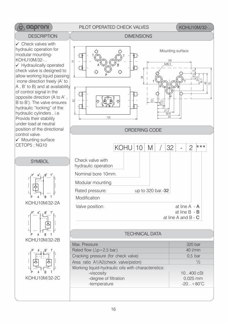
KOHU10M/32-...
ORDERING CODE
KOHU 10 M / 32 - 2 ***
Check valve with hydraulic operation
Modular mounting
: at line A - A at line B - B
at line A and B - C
Valve position
Rated pressure: up to 320 bar.-32
Nominal bore 10mm.
DESCRIPTION ORDERING CODE
Modification
TECHNICAL DATA
Max. Pressure 320 bar
Rated flow (Dp=2,5 bar.) 40 l/min
Cracking pressure (for check valve) 0,5 bar
Area ratio A1/A2(check valve/piston) ½Working liquid-hydraulic oils with characteristics: -viscosity 10...400 cSt -degree of filtration 0,025 mm
o -temperature -20...+80 C
ORDERING CODEDIMENSIONS
ORDERING CODE
SYMBOL
ORDERING CODE ORDERING CODEORDERING CODE
KOHU10M/32-2A
KOHU10M/32-2B
KOHU10M/32-2C
Check valves with hydraulic operation for modular mounting-KOHU10M/32-...
Hydraulically operatedcheck valve is designed toallow working liquid passing inone direction freely (A’ to A , B’ to B) and at availability of control signal in the opposite direction (A to A’ ,B to B’). The valve ensureshydraulic “locking” of thehydraulic cylinders , i.e.Provids their stability under load at neutral position of the directionalcontrol valve.
Mounting surface CETOP5 ; NG10
Mounting surface
PILOT OPERATED CHECK VALVES
17
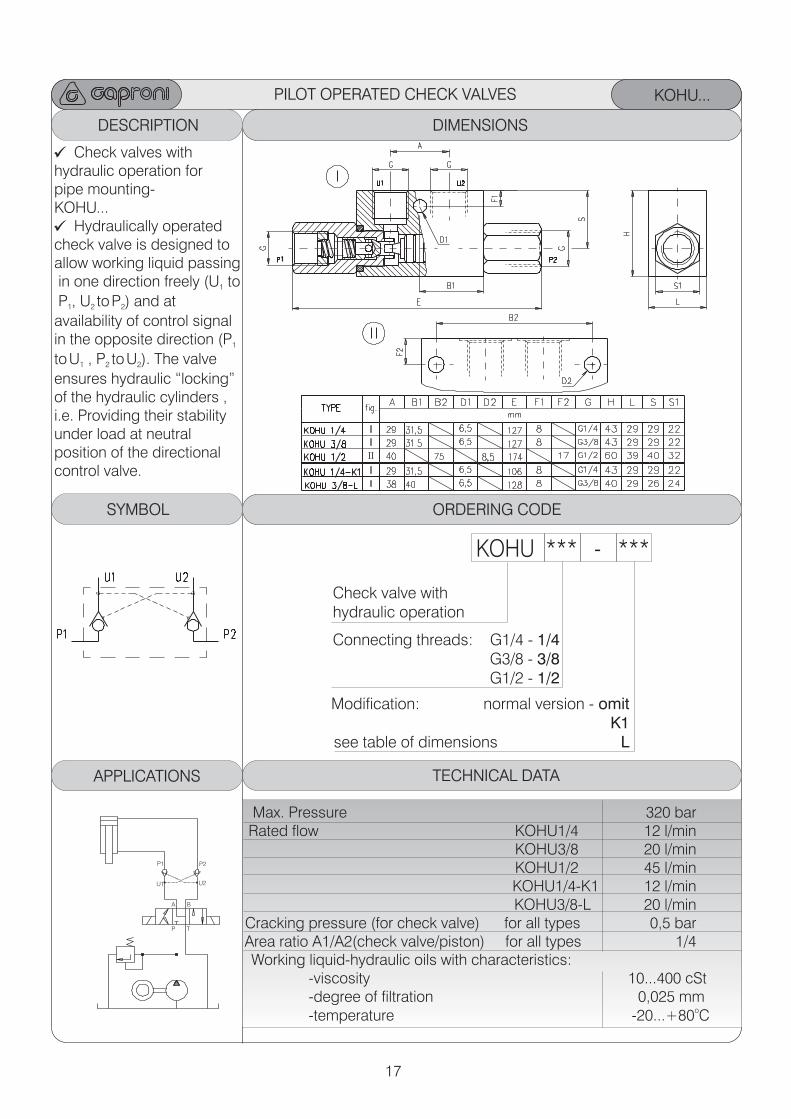
KOHU...
ORDERING CODE
KOHU *** - ***
Check valve with hydraulic operation
Connecting threads: G1/4 - 1/4 G3/8 - 3/8 G1/2 - 1/2
DESCRIPTION ORDERING CODE
Modification: normal version - omitK1
see table of dimensions L
TECHNICAL DATA
Max. Pressure 320 barRated flow KOHU1/4 12 l/min
KOHU3/8 20 l/min KOHU1/2 45 l/min KOHU1/4-K1 12 l/min KOHU3/8-L 20 l/min
Cracking pressure (for check valve) for all types 0,5 barArea ratio A1/A2(check valve/piston) for all types 1/4 Working liquid-hydraulic oils with characteristics: -viscosity 10...400 cSt -degree of filtration 0,025 mm
o -temperature -20...+80 C
ORDERING CODEDIMENSIONS
ORDERING CODESYMBOL ORDERING CODE ORDERING CODEORDERING CODE
Check valves with hydraulic operation for pipe mounting-KOHU...
Hydraulically operatedcheck valve is designed toallow working liquid passing in one direction freely (U to1
P , U toP ) and at 1 2 2
availability of control signal in the opposite direction (P1
toU , P toU ). The valve 1 2 2
ensures hydraulic “locking” of the hydraulic cylinders , i.e. Providing their stability under load at neutral position of the directionalcontrol valve.
PILOT OPERATED CHECK VALVES
APPLICATIONS
P1
P T
U1
P2
U2
A B
18
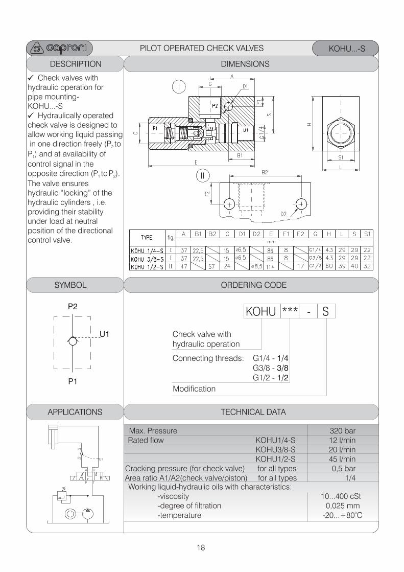
KOHU...-S
ORDERING CODE
KOHU *** - S
Check valve with hydraulic operation
Connecting threads: G1/4 - 1/4 G3/8 - 3/8 G1/2 - 1/2
DESCRIPTION ORDERING CODE
Modification
TECHNICAL DATA
Max. Pressure 320 barRated flow KOHU1/4-S 12 l/min KOHU3/8-S 20 l/min KOHU1/2-S 45 l/min
Cracking pressure (for check valve) for all types 0,5 barArea ratio A1/A2(check valve/piston) for all types 1/4 Working liquid-hydraulic oils with characteristics: -viscosity 10...400 cSt -degree of filtration 0,025 mm
o -temperature -20...+80 C
ORDERING CODEDIMENSIONS
ORDERING CODESYMBOL ORDERING CODE ORDERING CODEORDERING CODE
Check valves with hydraulic operation for pipe mounting-KOHU...-S
Hydraulically operatedcheck valve is designed toallow working liquid passing in one direction freely (P to2
P ) and at availability of1
control signal in the opposite direction (P toP ). 1 2
The valve ensureshydraulic “locking” of thehydraulic cylinders , i.e.providing their stability under load at neutral position of the directionalcontrol valve.
P1
P2
U1
PILOT OPERATED CHECK VALVES
Ø
Ø
Ø
APPLICATIONS
P1
P T
U1P2
A B
19
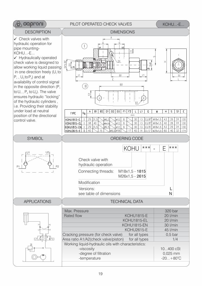
KOHU...-E...
ORDERING CODE
KOHU *** - E ***
Check valve with hydraulic operation
Connecting threads: M18x1,5 - 1815 M26x1,5 - 2615
DESCRIPTION ORDERING CODE
Modification
TECHNICAL DATA
Max. Pressure 320 barRated flow KOHU1815-E 20 l/min
KOHU1815-EL 20 l/min KOHU1815-EN 30 l/min
KOHU2615-E 45 l/min Cracking pressure (for check valve) for all types 0,5 barArea ratio A1/A2(check valve/piston) for all types 1/4 Working liquid-hydraulic oils with characteristics: -viscosity 10...400 cSt -degree of filtration 0,025 mm
o -temperature -20...+80 C
ORDERING CODEDIMENSIONS
ORDERING CODESYMBOL ORDERING CODE ORDERING CODEORDERING CODE
Check valves with hydraulic operation for pipe mounting-KOHU...-E...
Hydraulically operatedcheck valve is designed toallow working liquid passing in one direction freely (U to1
P , U toP ) and at 1 2 2
availability of control signal in the opposite direction (P1
toU , P toU ). The valve 1 2 2
ensures hydraulic “locking” of the hydraulic cylinders , i.e. Providing their stability under load at neutral position of the directionalcontrol valve.
Versions: Lsee table of dimensions N
PILOT OPERATED CHECK VALVES
APPLICATIONS
P1
P1
P T
U1
U1
P2
P2
U2
U2
A B
20
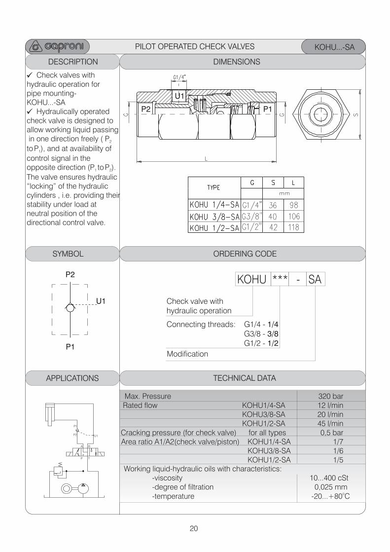
KOHU...-SA
ORDERING CODE
KOHU *** - SA
Check valve with hydraulic operation
Connecting threads: G1/4 - 1/4 G3/8 - 3/8 G1/2 - 1/2
DESCRIPTION ORDERING CODE
Modification
TECHNICAL DATA
Max. Pressure 320 barRated flow KOHU1/4-SA 12 l/min
KOHU3/8-SA 20 l/min KOHU1/2-SA 45 l/min Cracking pressure (for check valve) for all types 0,5 barArea ratio A1/A2(check valve/piston) KOHU1/4-SA 1/7
KOHU3/8-SA 1/6KOHU1/2-SA 1/5
Working liquid-hydraulic oils with characteristics: -viscosity 10...400 cSt -degree of filtration 0,025 mm
o -temperature -20...+80 C
ORDERING CODEDIMENSIONS
ORDERING CODESYMBOL ORDERING CODE ORDERING CODEORDERING CODE
Check valves with hydraulic operation for pipe mounting-KOHU...-SA
Hydraulically operatedcheck valve is designed toallow working liquid passing in one direction freely ( P2
toP ), and at availability of 1
control signal in the opposite direction (P toP ). 1 2
The valve ensures hydraulic “locking” of the hydraulic cylinders , i.e. providing their stability under load at neutral position of the directional control valve.
P1
P1
P2
P2
U1
U1
PILOT OPERATED CHECK VALVES
APPLICATIONS
P1
P T
U1P2
A B
21
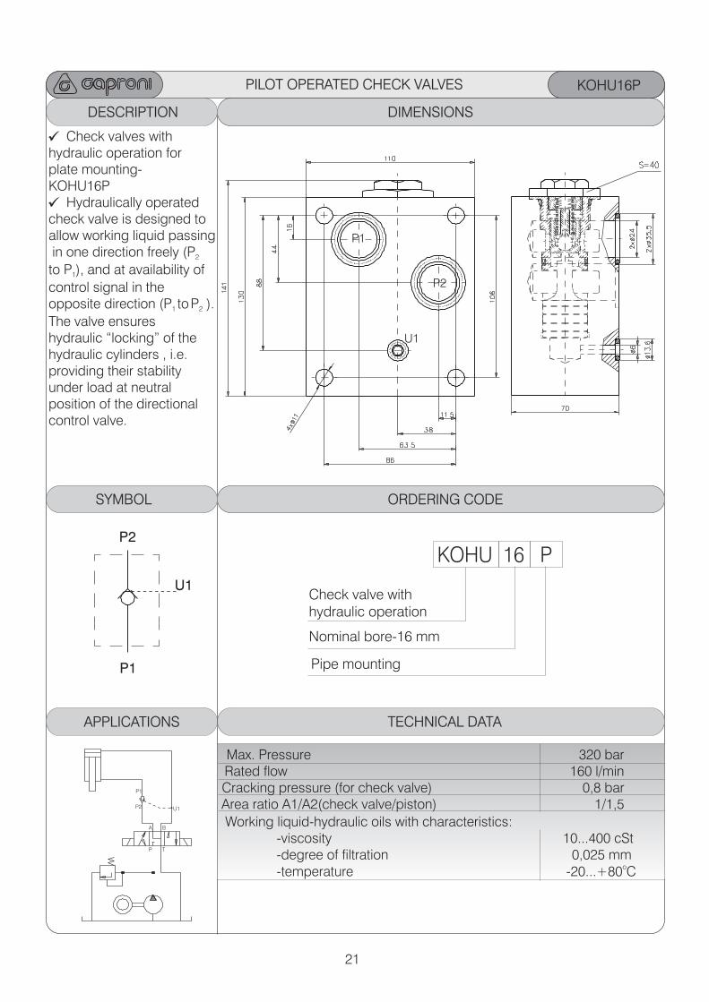
KOHU16P
ORDERING CODE
KOHU 16 P
Check valve with hydraulic operation
Nominal bore-16 mm
DESCRIPTION ORDERING CODE
TECHNICAL DATA
Max. Pressure 320 barRated flow 160 l/min Cracking pressure (for check valve) 0,8 barArea ratio A1/A2(check valve/piston) 1/1,5
Working liquid-hydraulic oils with characteristics: -viscosity 10...400 cSt -degree of filtration 0,025 mm
o -temperature -20...+80 C
ORDERING CODEDIMENSIONS
ORDERING CODESYMBOL ORDERING CODE ORDERING CODEORDERING CODE
Check valves with hydraulic operation for plate mounting-KOHU16P
Hydraulically operatedcheck valve is designed toallow working liquid passing in one direction freely (P 2
to P ), and at availability of1
control signal in the opposite direction (P toP ). 1 2
The valve ensureshydraulic “locking” of thehydraulic cylinders , i.e.providing their stability under load at neutral position of the directionalcontrol valve.
P1
P2
U1
P1
P2
U1
Pipe mounting
PILOT OPERATED CHECK VALVES
APPLICATIONS
P1
P T
U1P2
A B
22
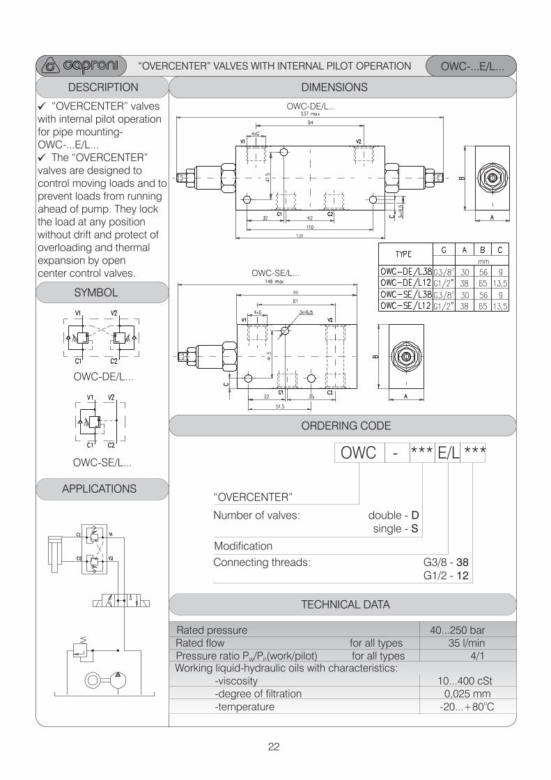
“OVERCENTER” VALVES WITH INTERNAL PILOT OPERATION OWC-...E/L...
ORDERING CODE
OWC - *** E/L ***
“OVERCENTER”
Number of valves: double - D single - S
DESCRIPTION ORDERING CODE
Modification
TECHNICAL DATA
Rated pressure 40...250 barRated flow for all types 35 l/min Pressure ratio P /P (work/pilot) for all types 4/1 W P
Working liquid-hydraulic oils with characteristics: -viscosity 10...400 cSt -degree of filtration 0,025 mm
o -temperature -20...+80 C
ORDERING CODEDIMENSIONS
ORDERING CODEORDERING CODE ORDERING CODEORDERING CODE
“OVERCENTER” valves with internal pilot operation for pipe mounting-OWC-...E/L...
The “OVERCENTER” valves are designed to control moving loads and toprevent loads from running ahead of pump. They lockthe load at any position without drift and protect of overloading and thermal expansion by open center control valves.
Connecting threads: G3/8 - 38 G1/2 - 12
OWC-DE/L...
OWC-SE/L...
SYMBOL
APPLICATIONS
OWC-DE/L...
OWC-SE/L...
Ø
Ø
130
95
23
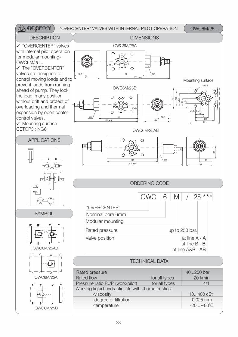
“OVERCENTER” VALVES WITH INTERNAL PILOT OPERATION OWC6M/25...
ORDERING CODEDESCRIPTION ORDERING CODE ORDERING CODEDIMENSIONS
“OVERCENTER” valves with internal pilot operation for modular mounting-OWC6M/25...
The “OVERCENTER” valves are designed to control moving loads and toprevent loads from running ahead of pump. They lockthe load in any position without drift and protect ofoverloading and thermal expansion by open center control valves.
Mounting surface CETOP3 ; NG6
OWC6M/25A
OWC6M/25B
OWC6M/25AB
OWC6M/25A
OWC6M/25B
OWC6M/25AB
ORDERING CODEORDERING CODE ORDERING CODEORDERING CODE
APPLICATIONS
OWC 6 M / 25 ***
“OVERCENTER”
Modular mounting Rated pressure up to 250 bar.
Valve position at line B - B at line A&B - AB
: at line A - A
Nominal bore 6mm
TECHNICAL DATA
Rated pressure 40...250 barRated flow for all types 20 l/min Pressure ratio P /P (work/pilot) for all types 4/1 W P
Working liquid-hydraulic oils with characteristics: -viscosity 10...400 cSt -degree of filtration 0,025 mm
o -temperature -20...+80 C
Mounting surface
SYMBOL
135
135
24
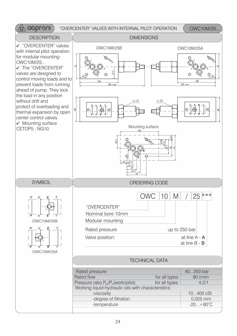
“OVERCENTER” VALVES WITH INTERNAL PILOT OPERATION OWC10M/25...
ORDERING CODEDESCRIPTION ORDERING CODE ORDERING CODEDIMENSIONS
“OVERCENTER” valves with internal pilot operation for modular mounting-OWC10M/25...
The “OVERCENTER” valves are designed to control moving loads and toprevent loads from running ahead of pump. They lockthe load in any position without drift andprotect of overloading andthermal expansion by open center control valves.
Mounting surface CETOP5 ; NG10
OWC10M/25AOWC10M/25B
OWC10M/25B
OWC10M/25A
ORDERING CODEORDERING CODE ORDERING CODEORDERING CODE
OWC 10 M / 25 ***
“OVERCENTER”
Modular mounting Rated pressure up to 250 bar.
Valve position at line B - B
: at line A - A
Nominal bore 10mm
TECHNICAL DATA
Rated pressure 40...250 bar Rated flow for all types 80 l/min
Pressure ratio P /P (work/pilot) for all types 4,2/1 W P
Working liquid-hydraulic oils with characteristics: -viscosity 10...400 cSt -degree of filtration 0,025 mm
o -temperature -20...+80 C
SYMBOL
Mounting surface
25
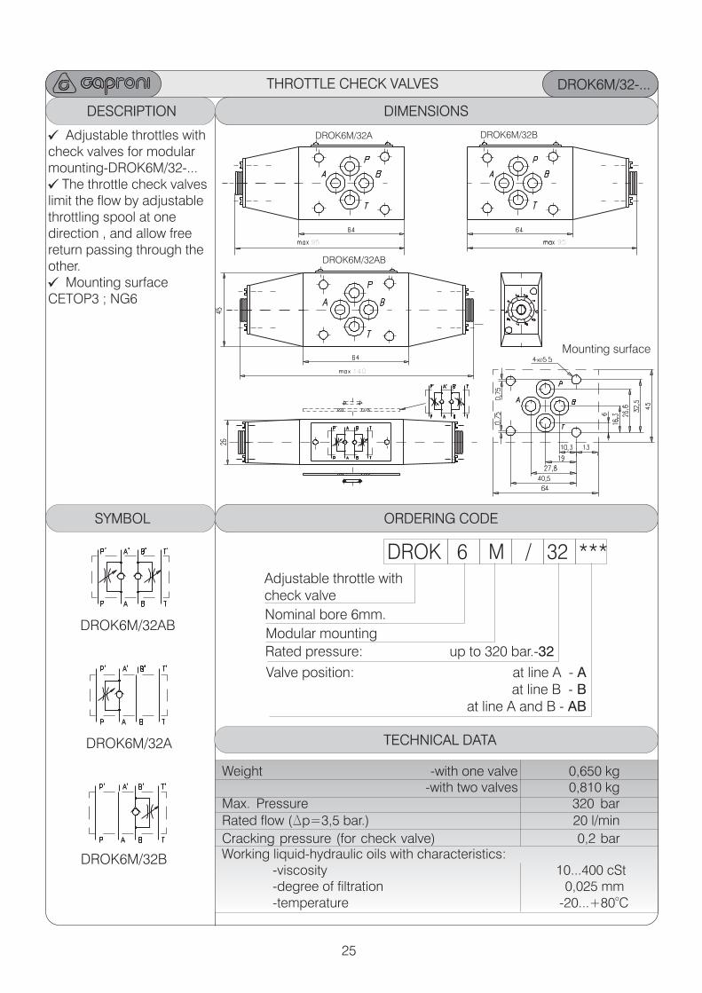
THROTTLE CHECK VALVES DROK6M/32-...
ORDERING CODEDESCRIPTION ORDERING CODE ORDERING CODEDIMENSIONS
DROK6M/32A DROK6M/32B
95 95
DROK6M/32AB
140
Mounting surfaceØ
Adjustable throttles withcheck valves for modular mounting-DROK6M/32-...
The throttle check valveslimit the flow by adjustable throttling spool at one direction , and allow freereturn passing through the other.
Mounting surface CETOP3 ; NG6
ORDERING CODESYMBOL ORDERING CODE ORDERING CODEORDERING CODE
DROK 6 M / 32 *** Adjustable throttle withcheck valve
Modular mounting
: at line A - A at line B - B
at line A and B - AB
Valve position
Rated pressure: up to 320 bar.-32
Nominal bore 6mm.
TECHNICAL DATA
Weight -with one valve 0,650 kg -with two valves 0,810 kgMax. Pressure 320 bar
Rated flow (Dp=3,5 bar.) 20 l/min
Cracking pressure (for check valve) 0,2 barWorking liquid-hydraulic oils with characteristics: -viscosity 10...400 cSt -degree of filtration 0,025 mm
o -temperature -20...+80 C
DROK6M/32A
DROK6M/32B
DROK6M/32AB
142,5 142,5
26
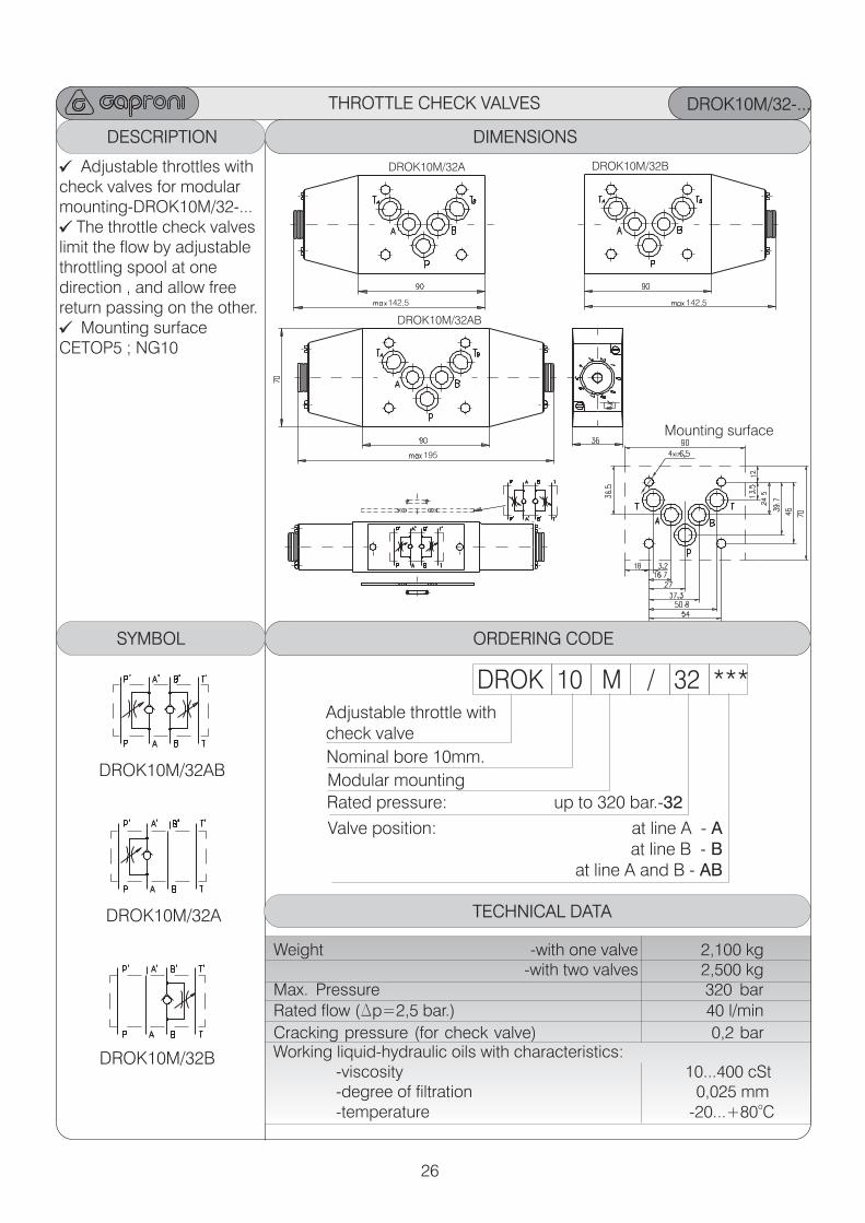
DROK10M/32-...
ORDERING CODEDESCRIPTION ORDERING CODE ORDERING CODEDIMENSIONS
DROK10M/32A DROK10M/32B
DROK10M/32AB
Mounting surface
Adjustable throttles withcheck valves for modular mounting-DROK10M/32-...
The throttle check valveslimit the flow by adjustable throttling spool at one direction , and allow freereturn passing on the other.
Mounting surface CETOP5 ; NG10
ORDERING CODESYMBOL ORDERING CODE ORDERING CODEORDERING CODE
DROK 10 M / 32 *** Adjustable throttle withcheck valve
Modular mounting
: at line A - A at line B - B
at line A and B - AB
Valve position
Rated pressure: up to 320 bar.-32
Nominal bore 10mm.
TECHNICAL DATA
Weight -with one valve 2,100 kg -with two valves 2,500 kgMax. Pressure 320 bar
Rated flow (Dp=2,5 bar.) 40 l/min
Cracking pressure (for check valve) 0,2 barWorking liquid-hydraulic oils with characteristics: -viscosity 10...400 cSt -degree of filtration 0,025 mm
o -temperature -20...+80 C
DROK10M/32A
DROK10M/32B
DROK10M/32AB
195 Ø
THROTTLE CHECK VALVES
27
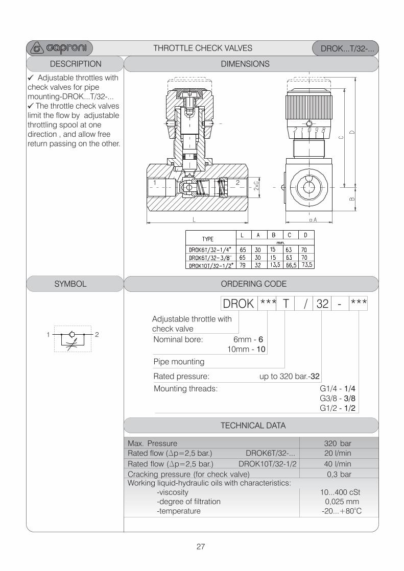
DROK...T/32-...
ORDERING CODEDESCRIPTION ORDERING CODE ORDERING CODEDIMENSIONS
Adjustable throttles withcheck valves for pipe mounting-DROK...T/32-...
The throttle check valveslimit the flow by adjustable throttling spool at one direction , and allow freereturn passing on the other.
ORDERING CODESYMBOL ORDERING CODE ORDERING CODEORDERING CODE
DROK *** T / 32 - *** Adjustable throttle withcheck valve
Pipe mounting
Mounting threads: G1/4 - 1/4 G3/8 - 3/8
G1/2 - 1/2
Rated pressure: up to 320 bar.-32
Nominal bore: 6mm - 6 10mm - 10
TECHNICAL DATA
Max. Pressure 320 bar
Rated flow (Dp=2,5 bar.) DROK6T/32-... 20 l/min
Rated flow (Dp=2,5 bar.) DROK10T/32-1/2 40 l/min
Cracking pressure (for check valve) 0,3 barWorking liquid-hydraulic oils with characteristics: -viscosity 10...400 cSt -degree of filtration 0,025 mm
o -temperature -20...+80 C
THROTTLE CHECK VALVES
1
1
2
2
28
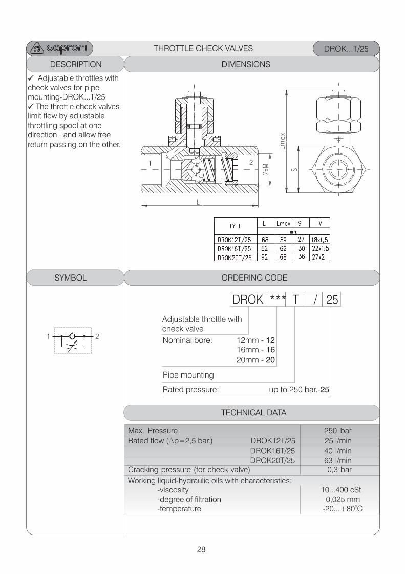
DROK...T/25
ORDERING CODEDESCRIPTION ORDERING CODE ORDERING CODEDIMENSIONS
Adjustable throttles withcheck valves for pipe mounting-DROK...T/25
The throttle check valveslimit flow by adjustable throttling spool at one direction , and allow freereturn passing on the other.
ORDERING CODESYMBOL ORDERING CODE ORDERING CODEORDERING CODE
DROK *** T / 25
Adjustable throttle withcheck valve
Pipe mounting
Rated pressure: up to 250 bar.-25
Nominal bore: 12mm - 12 16mm - 16 20mm - 20
TECHNICAL DATA
Max. Pressure 250 bar
Rated flow (Dp=2,5 bar.) DROK12T/25 25 l/min
DROK16T/25 40 l/min DROK20T/25 63 l/minCracking pressure (for check valve) 0,3 bar
Working liquid-hydraulic oils with characteristics: -viscosity 10...400 cSt -degree of filtration 0,025 mm
o -temperature -20...+80 C
THROTTLE CHECK VALVES
1
1
2
2
29
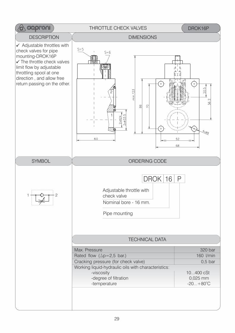
DROK16P
ORDERING CODEDESCRIPTION ORDERING CODE ORDERING CODEDIMENSIONS
Adjustable throttles withcheck valves for pipe mounting-DROK16P
The throttle check valveslimit flow by adjustable throttling spool at one direction , and allow freereturn passing on the other.
ORDERING CODESYMBOL ORDERING CODE ORDERING CODEORDERING CODE
DROK 16 P
Adjustable throttle withcheck valve
Pipe mounting
Nominal bore - 16 mm.
TECHNICAL DATA
Max. Pressure 320 bar
Rated flow (Dp=2,5 bar.) 160 l/min
Cracking pressure (for check valve) 0,5 barWorking liquid-hydraulic oils with characteristics: -viscosity 10...400 cSt -degree of filtration 0,025 mm
o -temperature -20...+80 C
THROTTLE CHECK VALVES
1
1
2
2
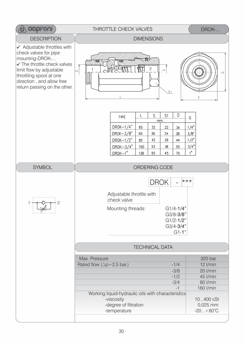
30
DROK-...
ORDERING CODEDESCRIPTION ORDERING CODE ORDERING CODEDIMENSIONS
Adjustable throttles withcheck valves for pipe mounting-DROK-...
The throttle check valveslimit flow by adjustable throttling spool at one direction , and allow freereturn passing on the other.
ORDERING CODESYMBOL ORDERING CODE ORDERING CODEORDERING CODE
DROK - ***
Adjustable throttle withcheck valve
Mounting threads: G1/4-1/4” G3/8-3/8” G1/2-1/2” G3/4-3/4”
G1-1”
THROTTLE CHECK VALVES
1
1
2
2
TECHNICAL DATA
Max. Pressure 320 bar
Rated flow (Dp=2,5 bar.) -1/4 12 l/min
-3/8 20 l/min -1/2 45 l/min
-3/4 80 l/min -1 160 l/min
Working liquid-hydraulic oils with characteristics: -viscosity 10...400 cSt -degree of filtration 0,025 mm
o -temperature -20...+80 C
31
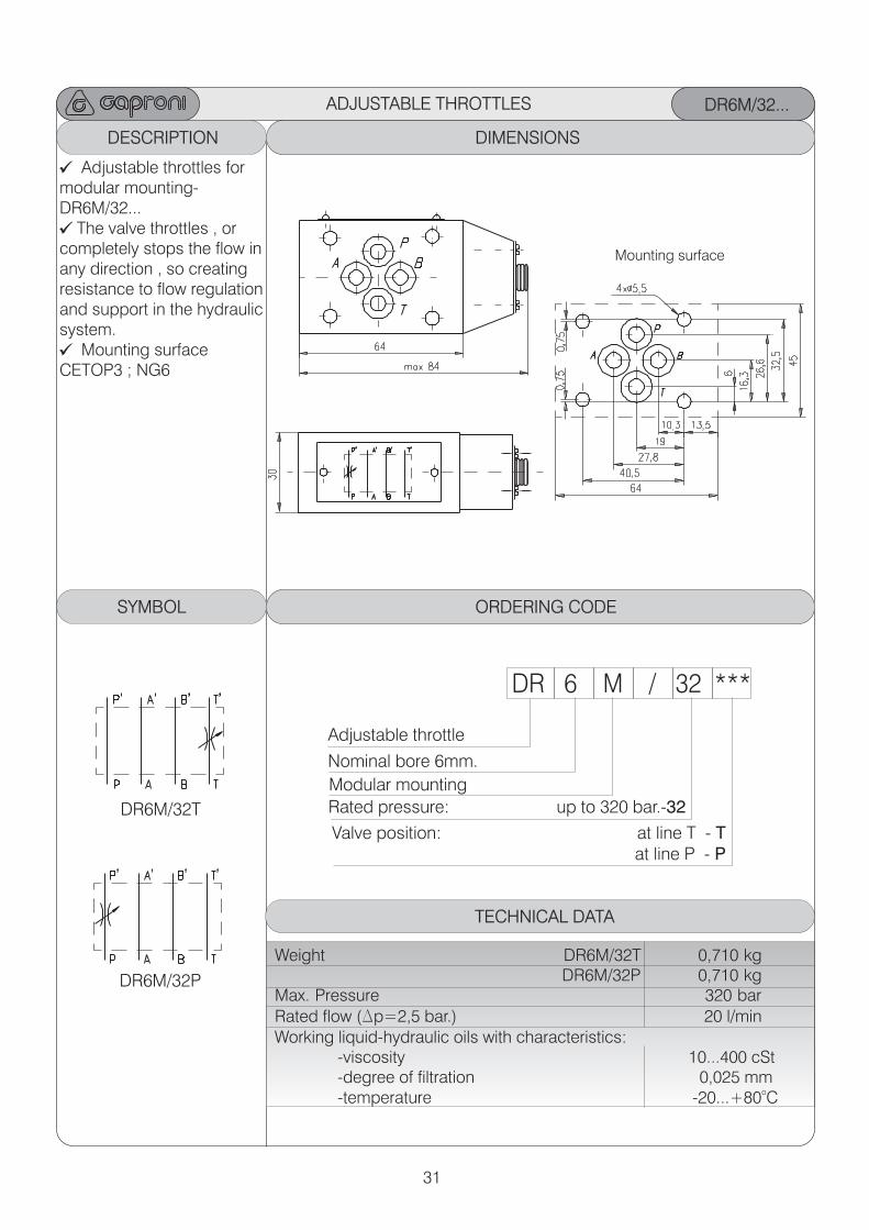
ADJUSTABLE THROTTLES DR6M/32...
ORDERING CODEDESCRIPTION ORDERING CODE ORDERING CODEDIMENSIONS
Mounting surface
Adjustable throttles for modular mounting-DR6M/32...
The valve throttles , or completely stops the flow inany direction , so creating resistance to flow regulationand support in the hydraulicsystem.
Mounting surface CETOP3 ; NG6
ORDERING CODESYMBOL ORDERING CODE ORDERING CODEORDERING CODE
DR 6 M / 32 ***
Adjustable throttle
Modular mounting
: at line T - T at line P - P
Valve position
Rated pressure: up to 320 bar.-32
Nominal bore 6mm.
TECHNICAL DATA
Weight DR6M/32T 0,710 kg DR6M/32P 0,710 kgMax. Pressure 320 bar
Rated flow (Dp=2,5 bar.) 20 l/minWorking liquid-hydraulic oils with characteristics: -viscosity 10...400 cSt -degree of filtration 0,025 mm
o -temperature -20...+80 C
DR6M/32T
DR6M/32P
32
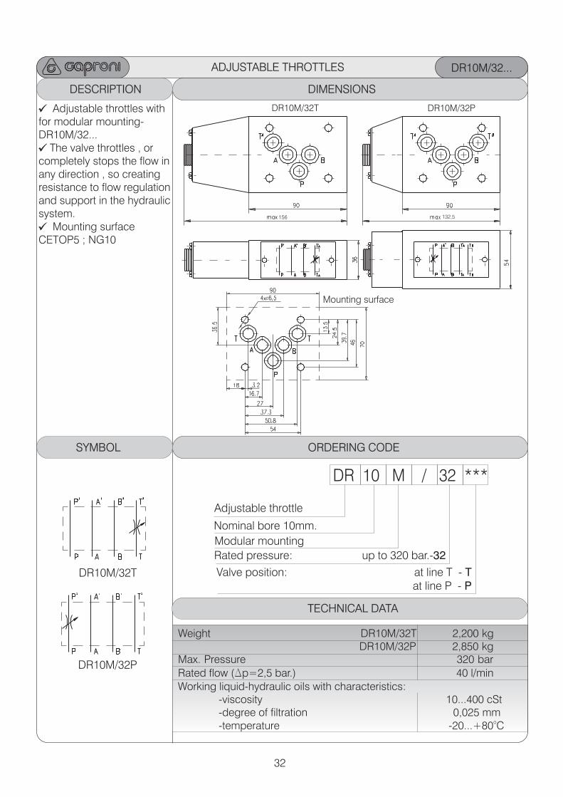
ADJUSTABLE THROTTLES DR10M/32...
ORDERING CODEDESCRIPTION ORDERING CODE ORDERING CODEDIMENSIONS
Mounting surface
Adjustable throttles with for modular mounting-DR10M/32...
The valve throttles , or completely stops the flow inany direction , so creating resistance to flow regulationand support in the hydraulicsystem.
Mounting surface CETOP5 ; NG10
ORDERING CODESYMBOL ORDERING CODE ORDERING CODEORDERING CODE
DR 10 M / 32 ***
Adjustable throttle
Modular mounting
: at line T - T at line P - P
Valve position
Rated pressure: up to 320 bar.-32
Nominal bore 10mm.
TECHNICAL DATA
Weight DR10M/32T 2,200 kg DR10M/32P 2,850 kgMax. Pressure 320 bar
Rated flow (Dp=2,5 bar.) 40 l/minWorking liquid-hydraulic oils with characteristics: -viscosity 10...400 cSt -degree of filtration 0,025 mm
o -temperature -20...+80 C
DR10M/32T
DR10M/32P
DR10M/32T DR10M/32P
Ø
156 132,5
33
DESCRIPTION DIMENSIONS
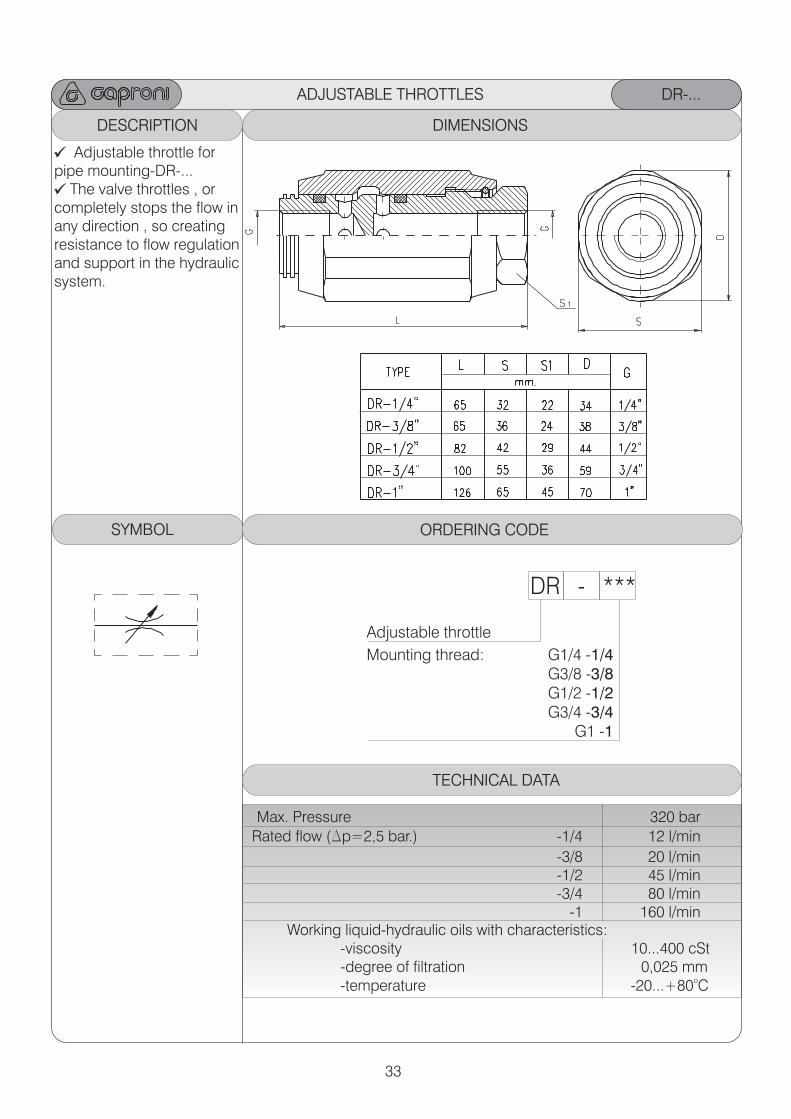
DR-...
ORDERING CODE
DR - ***
Adjustable throttle Mounting thread: G1/4 -1/4
G3/8 -3/8 G1/2 -1/2 G3/4 -3/4
G1 -1
TECHNICAL DATA
SYMBOL
Adjustable throttle for pipe mounting-DR-...
The valve throttles , or completely stops the flow inany direction , so creating resistance to flow regulationand support in the hydraulicsystem.
Max. Pressure 320 bar
Rated flow (Dp=2,5 bar.) -1/4 12 l/min
-3/8 20 l/min -1/2 45 l/min
-3/4 80 l/min -1 160 l/min
Working liquid-hydraulic oils with characteristics: -viscosity 10...400 cSt -degree of filtration 0,025 mm
o -temperature -20...+80 C
ADJUSTABLE THROTTLES
34
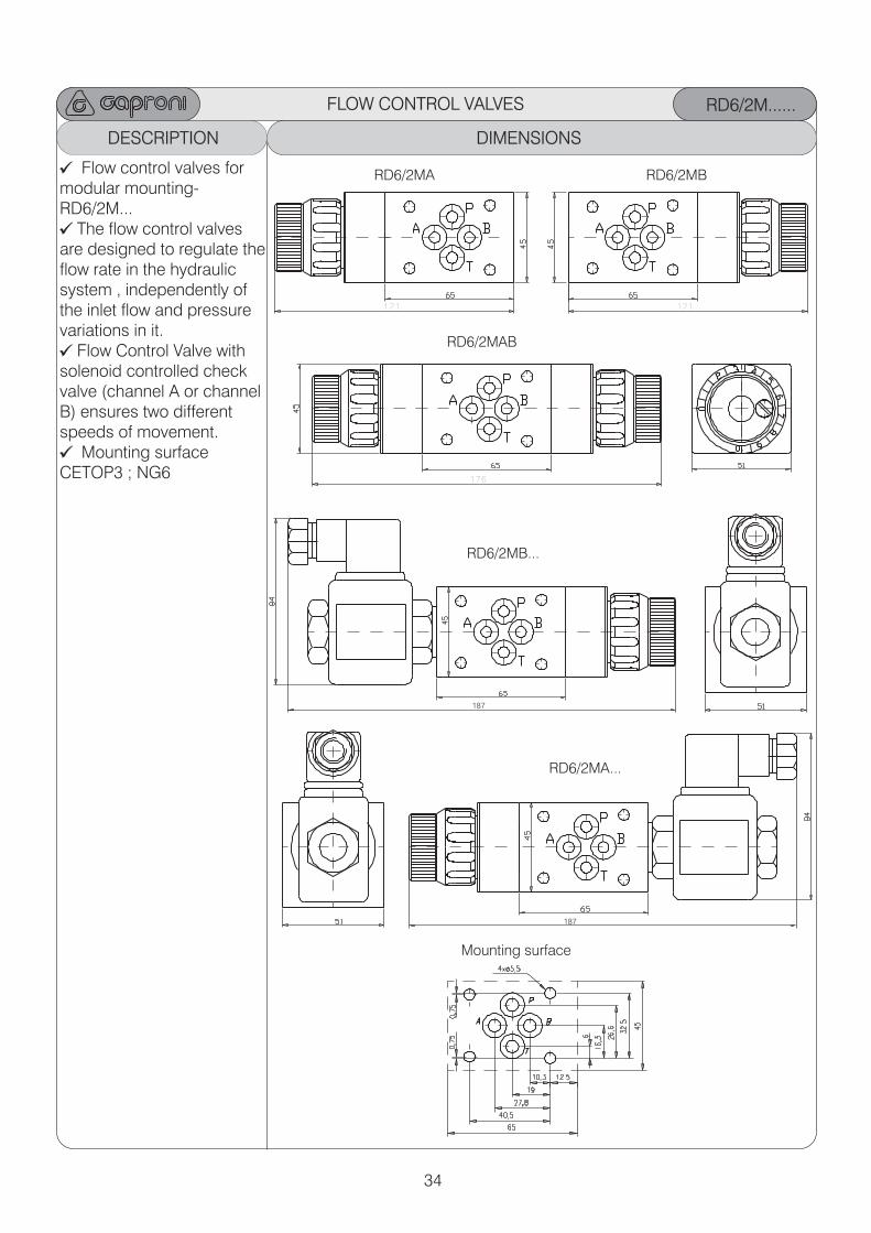
FLOW CONTROL VALVES RD6/2M......
ORDERING CODEDESCRIPTION ORDERING CODE ORDERING CODEDIMENSIONS
Flow control valves for modular mounting-RD6/2M...
The flow control valves are designed to regulate theflow rate in the hydraulic system , independently of the inlet flow and pressure variations in it.
Flow Control Valve withsolenoid controlled checkvalve (channel A or channel B) ensures two differentspeeds of movement.
Mounting surface CETOP3 ; NG6
Mounting surface
RD6/2MAB
RD6/2MB
RD6/2MB...
121
176
187
187
RD6/2MA
121
RD6/2MA...
35
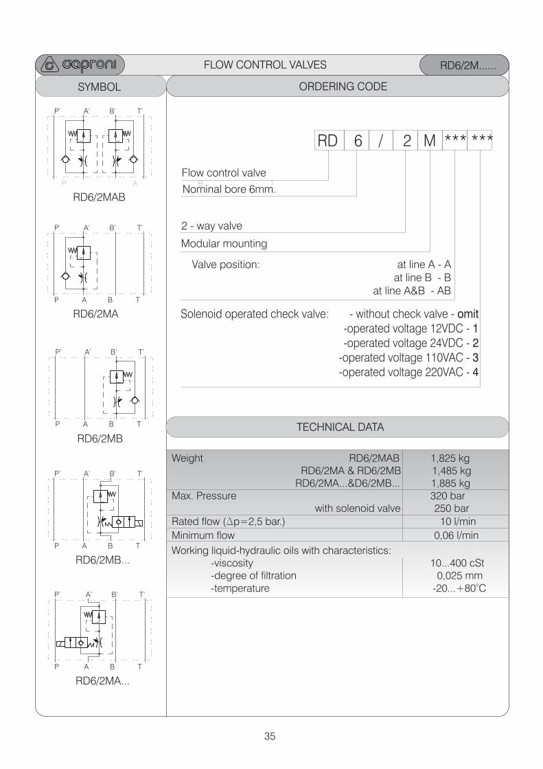
FLOW CONTROL VALVES RD6/2M......
ORDERING CODEORDERING CODE ORDERING CODESYMBOL ORDERING CODE
RD 6 / 2 M *** ***
Flow control valve
2 - way valve
: at line B - B
at line A&B - AB
Valve position at line A - A
Modular mounting
Solenoid operated check valve: - without check valve - omit-operated voltage 12VDC - 1-operated voltage 24VDC - 2
-operated voltage 110VAC - 3-operated voltage 220VAC - 4
Nominal bore 6mm.
TECHNICAL DATA
Weight RD6/2MAB 1,825 kg RD6/2MA & RD6/2MB 1,485 kg RD6/2MA...&D6/2MB... 1,885 kg Max. Pressure 320 bar with solenoid valve 250 bar
Rated flow (Dp=2,5 bar.) 10 l/min
Minimum flow 0,06 l/min
Working liquid-hydraulic oils with characteristics: -viscosity 10...400 cSt -degree of filtration 0,025 mm
o -temperature -20...+80 C
RD6/2MAB
RD6/2MB
RD6/2MB...
P A B T
P’ A’ B’ T’
P A B T
P’ A’ B’ T’
P A B T
P’ A’ B’ T’
RD6/2MA
P A B T
P’ A’ B’ T’
RD6/2MA...
P A B T
P’ A’ B’ T’
36
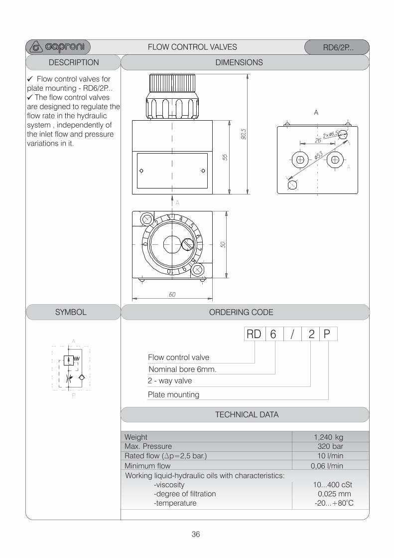
FLOW CONTROL VALVES RD6/2P...
ORDERING CODEDESCRIPTION ORDERING CODE ORDERING CODEDIMENSIONS
Flow control valves for plate mounting - RD6/2P...
The flow control valves are designed to regulate theflow rate in the hydraulic system , independently of the inlet flow and pressure variations in it.
A
A
RD 6 / 2 P
Flow control valve
2 - way valve
Plate mounting
Nominal bore 6mm.
ORDERING CODESYMBOL
TECHNICAL DATA
Weight 1,240 kgMax. Pressure 320 bar
Rated flow (Dp=2,5 bar.) 10 l/min
Minimum flow 0,06 l/min
Working liquid-hydraulic oils with characteristics: -viscosity 10...400 cSt -degree of filtration 0,025 mm
o -temperature -20...+80 C
P
P
A
A
37
“O” ring 12x2
“O” ring 20x2,65
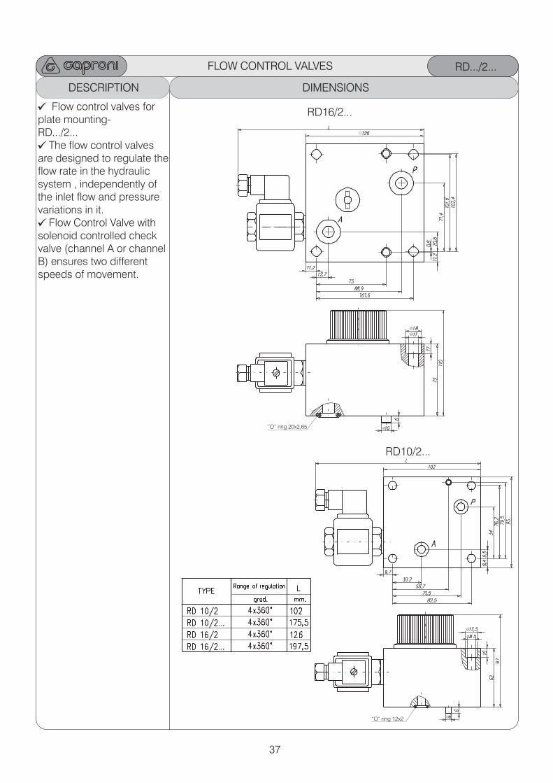
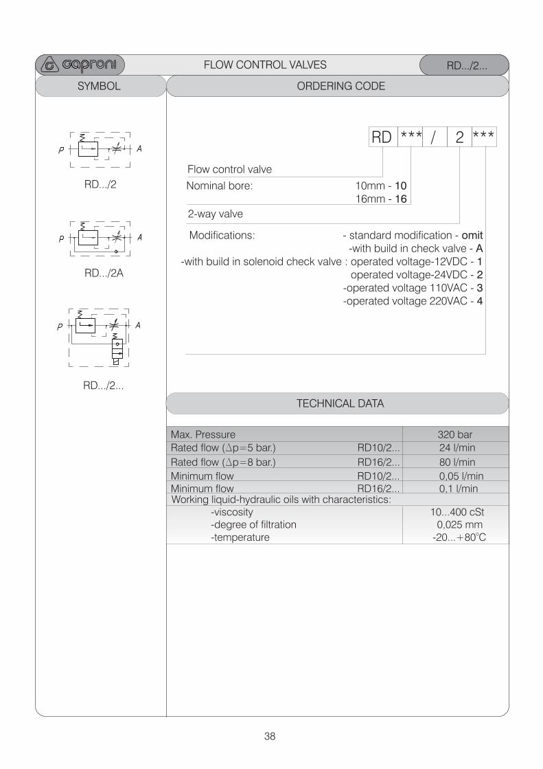
FLOW CONTROL VALVES RD.../2...
ORDERING CODEDESCRIPTION ORDERING CODE ORDERING CODEDIMENSIONS
Flow control valves for plate mounting-RD.../2...
The flow control valves are designed to regulate theflow rate in the hydraulic system , independently of the inlet flow and pressure variations in it.
Flow Control Valve withsolenoid controlled checkvalve (channel A or channel B) ensures two differentspeeds of movement.
RD16/2...
RD10/2...
Ø
Ø
Ø
Ø
Ø
Ø
38
FLOW CONTROL VALVES RD.../2...
ORDERING CODESYMBOL ORDERING CODE ORDERING CODEORDERING CODE
RD *** / 2 ***
Flow control valve
2-way valve
Modifications: - standard modification - omit-with build in check valve - A
-with build in solenoid check valve : operated voltage-12VDC - 1operated voltage-24VDC - 2
-operated voltage 110VAC - 3-operated voltage 220VAC - 4
Nominal bore: 10mm - 10 16mm - 16
TECHNICAL DATA
Max. Pressure 320 bar
Rated flow (Dp=5 bar.) RD10/2... 24 l/min
Rated flow (Dp=8 bar.) RD16/2... 80 l/min
Minimum flow RD10/2... 0,05 l/minMinimum flow RD16/2... 0,1 l/min
Working liquid-hydraulic oils with characteristics: -viscosity 10...400 cSt -degree of filtration 0,025 mm
o -temperature -20...+80 C
RD.../2
RD.../2A
RD.../2...
39
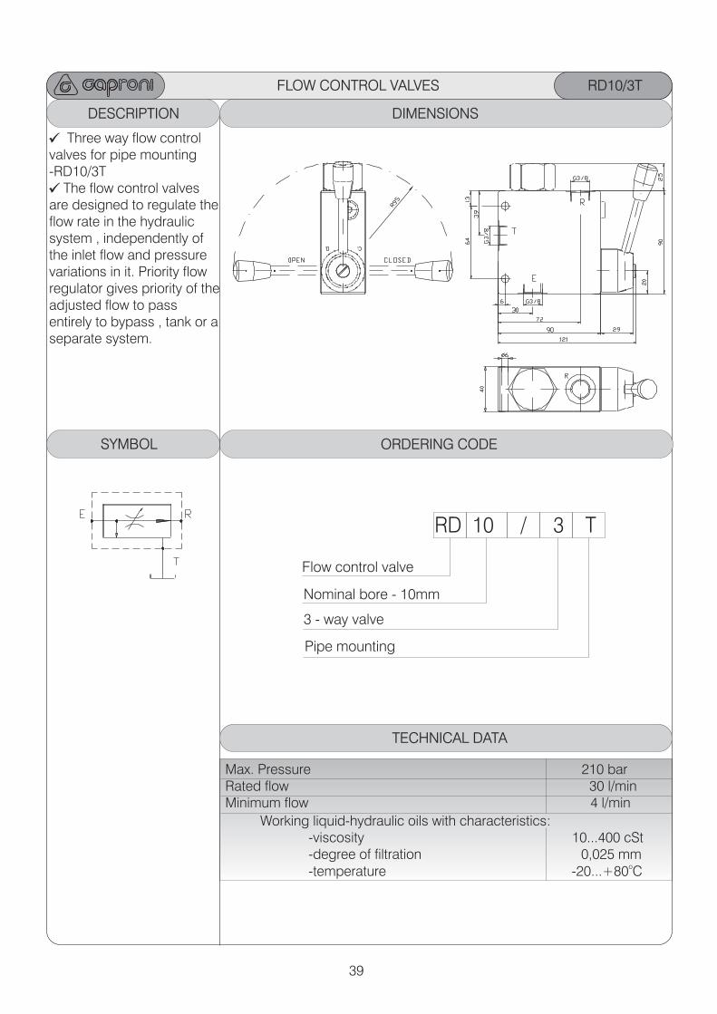
DESCRIPTION DIMENSIONS
RD10/3T
ORDERING CODE
RD 10 / 3 T
Flow control valve
Nominal bore - 10mm 3 - way valve
TECHNICAL DATA
Three way flow control valves for pipe mounting-RD10/3T
The flow control valves are designed to regulate theflow rate in the hydraulic system , independently of the inlet flow and pressure variations in it. Priority flowregulator gives priority of theadjusted flow to pass entirely to bypass , tank or aseparate system.
Max. Pressure 210 bar Rated flow 30 l/min Minimum flow 4 l/min Working liquid-hydraulic oils with characteristics:
-viscosity 10...400 cSt -degree of filtration 0,025 mm
o -temperature -20...+80 C
FLOW CONTROL VALVES
SYMBOL
Pipe mounting
40
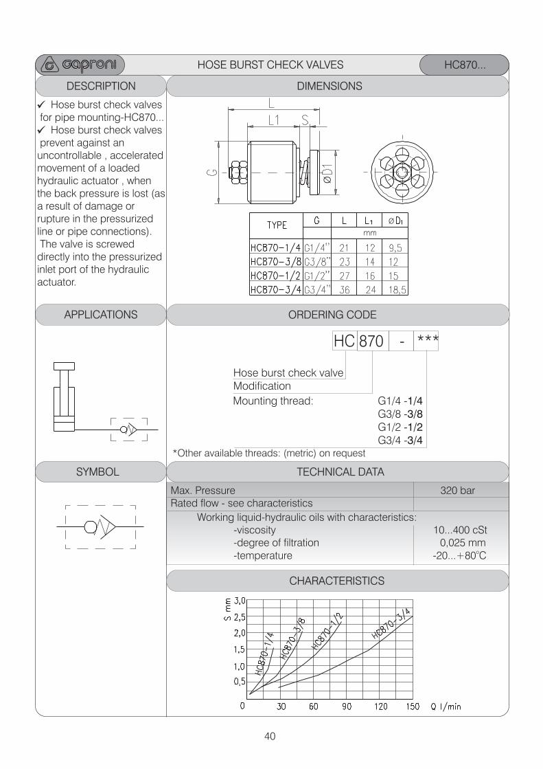
DESCRIPTION DIMENSIONS
HC870...
ORDERING CODE
HC 870 - ***
Hose burst check valveModification
*Other available threads: (metric) on request
Mounting thread: G1/4 -1/4
G3/8 -3/8 G1/2 -1/2 G3/4 -3/4
TECHNICAL DATA
APPLICATIONS
Hose burst check valves for pipe mounting-HC870...
Hose burst check valves prevent against an uncontrollable , acceleratedmovement of a loaded hydraulic actuator , when the back pressure is lost (asa result of damage or rupture in the pressurized line or pipe connections). The valve is screwed directly into the pressurizedinlet port of the hydraulicactuator.
Max. Pressure 320 bar Rated flow - see characteristics Working liquid-hydraulic oils with characteristics:
-viscosity 10...400 cSt -degree of filtration 0,025 mm
o -temperature -20...+80 C
HOSE BURST CHECK VALVES
SYMBOL
Ø
CHARACTERISTICS
Ø
41
DESCRIPTION DIMENSIONS
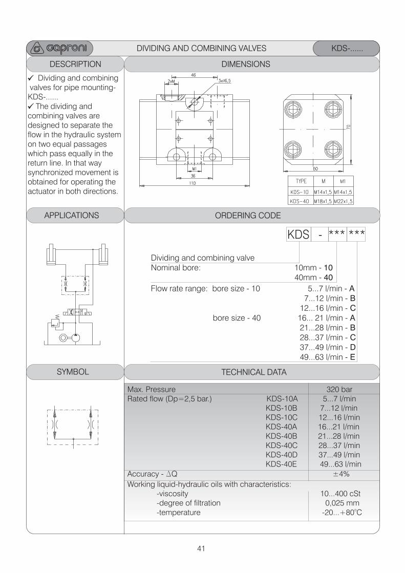
KDS-......
ORDERING CODEAPPLICATIONS
KDS - *** ***
Dividing and combining valveNominal bore: 10mm - 10 40mm - 40
Flow rate range: bore size - 10 5...7 l/min - A 7...12 l/min - B 12...16 l/min - C bore size - 40 16... 21 l/min - A 21...28 l/min - B 28...37 l/min - C 37...49 l/min - D 49...63 l/min - E
TECHNICAL DATA
Dividing and combining valves for pipe mounting-KDS-......
The dividing and combining valves are designed to separate the flow in the hydraulic system on two equal passages which pass equally in the return line. In that way synchronized movement is obtained for operating theactuator in both directions.
DIVIDING AND COMBINING VALVES
SYMBOL
Ø
Max. Pressure 320 barRated flow (Dp=2,5 bar.) KDS-10A 5...7 l/min KDS-10B 7...12 l/min KDS-10C 12...16 l/min KDS-40A 16...21 l/min KDS-40B 21...28 l/min KDS-40C 28...37 l/min KDS-40D 37...49 l/min KDS-40E 49...63 l/min
Accuracy - DQ ±4%
Working liquid-hydraulic oils with characteristics: -viscosity 10...400 cSt -degree of filtration 0,025 mm
o -temperature -20...+80 C
42
DESCRIPTION DIMENSIONS
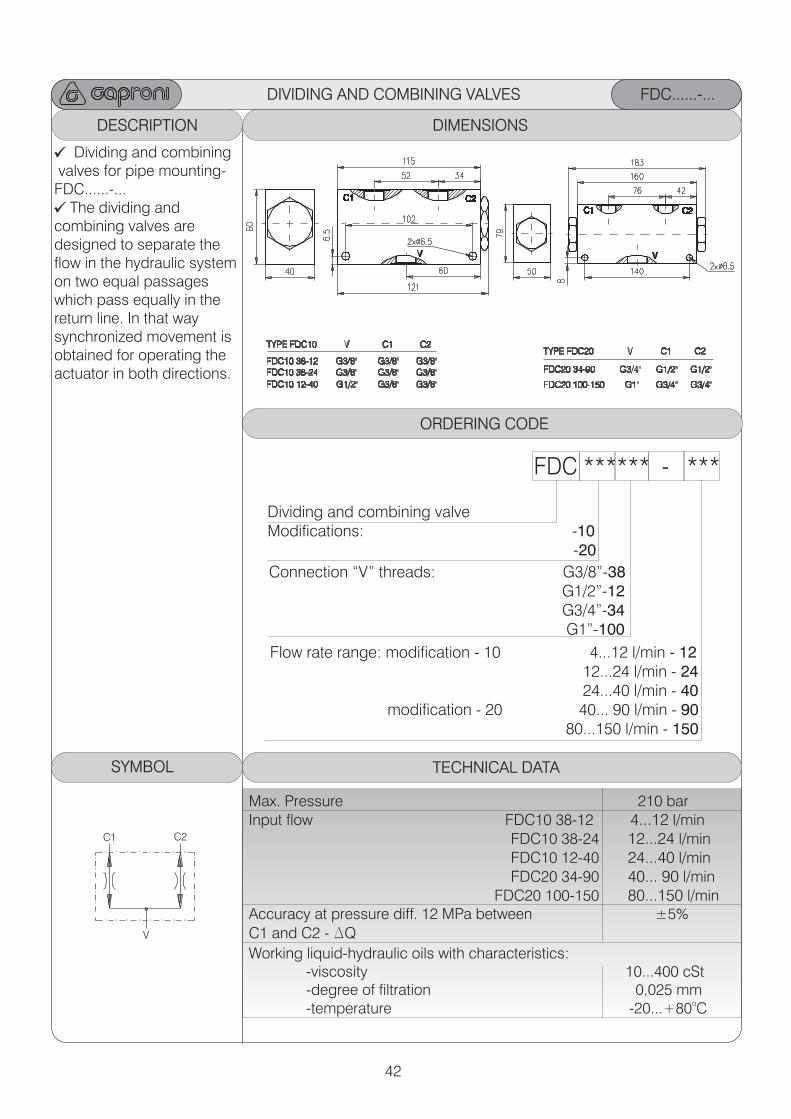
FDC......-...
ORDERING CODE
FDC ****** - ***
Dividing and combining valveModifications: -10 -20
Flow rate range: modification - 10 4...12 l/min - 12 12...24 l/min - 24 24...40 l/min - 40 modification - 20 40... 90 l/min - 90 80...150 l/min - 150 TECHNICAL DATA
Dividing and combining valves for pipe mounting-FDC......-...
The dividing and combining valves are designed to separate the flow in the hydraulic system on two equal passages which pass equally in the return line. In that way synchronized movement is obtained for operating theactuator in both directions.
DIVIDING AND COMBINING VALVES
SYMBOL
Max. Pressure 210 barInput flow FDC10 38-12 4...12 l/min FDC10 38-24 12...24 l/min FDC10 12-40 24...40 l/min FDC20 34-90 40... 90 l/min FDC20 100-150 80...150 l/minAccuracy at pressure diff. 12 MPa between ±5%
C1 and C2 - DQ
Working liquid-hydraulic oils with characteristics: -viscosity 10...400 cSt -degree of filtration 0,025 mm
o -temperature -20...+80 C
Connection “V” threads: G3/8”-38 G1/2”-12 G3/4”-34 G1”-100
V
C1 C2
43
FEATURES
HYDRAULIC POWER PACKS
Compact power unitsdesign.
Right power pack size foreach application and suitable circuit.
Required functions for allcontrol problems.
Stable steel reservoir withvisual oil level , filling plugwith air filter and drain plug.
Suitable devices for alladditional requests such as e.q. accumulator ; heatexchangers ; level , pressureand filtration supervisingapparatus etc.
Arrangement for servicemaintenance.
Individual adjustment ispossible.
Additional options at request.
Drive power units supply hydraulic consumers for various application. Customized hydraulic power units are consisted of: -Electric motor: three phases , V220/380 , 50Hz , shape V1 ,B5 or B3/B5 , B14 and power from 0,37 to 18,5kW.
3 -Hydraulic external gear pump: displacement from 1 to 60cm ,
pressure - up to 250bar.
-Reservoir with capacity: from 20 to 400 liters or more. -Manifolds for distribution and regulation of hydraulic power
according to the specific application. Customized circuits can be easily realized by means of modularplates , modular valves - size 06 and 10 ; solenoid valves anddirectional control valves.
Installation position horizontal -electric motor with vertical axis and pump submersed -electric motor installed on the reservoir cover with horizontal axis and pump
oAmbient temperature -20...+70 C Working liquid-hydraulic oils with parameters: -viscosity 10...400 cSt -recommended viscosity 20...80 cSt -degree of filtration 0,025 mm
o -temperature up to 80 C -fluid contamination class ISO 19/16
TECHNICAL DATA
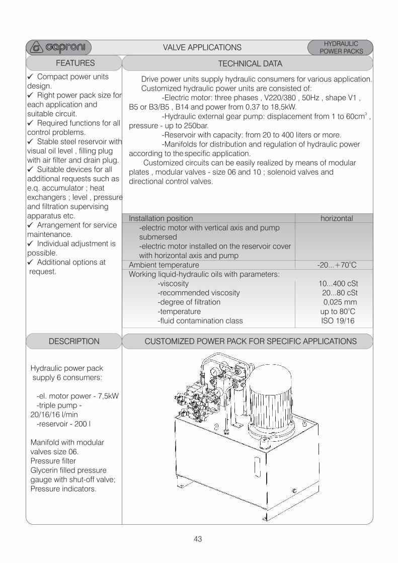
DESCRIPTION CUSTOMIZED POWER PACK FOR SPECIFIC APPLICATIONS
VALVE APPLICATIONS
Hydraulic power pack supply 6 consumers:
-el. motor power - 7,5kW -triple pump - 20/16/16 l/min -reservoir - 200 l
Manifold with modularvalves size 06.Pressure filter Glycerin filled pressuregauge with shut-off valve;Pressure indicators.
44
HYDRAULIC POWER PACKS
VALVE APPLICATIONS
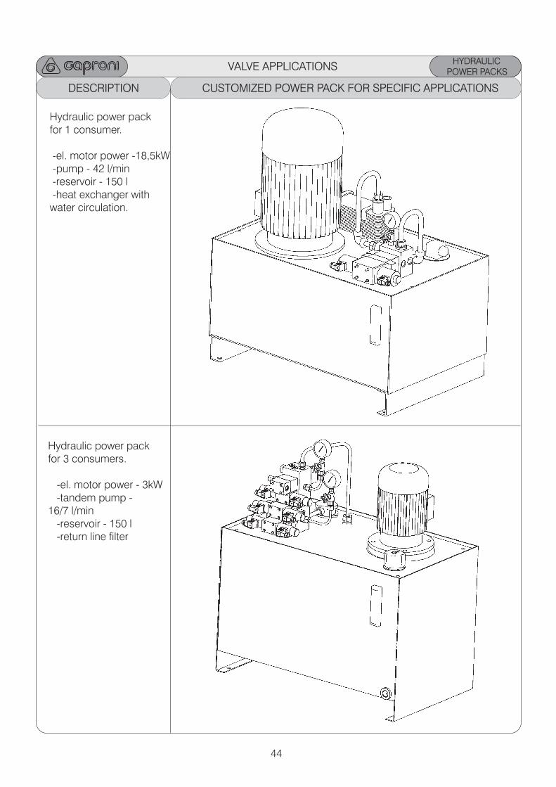
DESCRIPTION CUSTOMIZED POWER PACK FOR SPECIFIC APPLICATIONS
Hydraulic power packfor 3 consumers.
-el. motor power - 3kW -tandem pump - 16/7 l/min -reservoir - 150 l -return line filter
Hydraulic power packfor 1 consumer.
-el. motor power -18,5kW -pump - 42 l/min -reservoir - 150 l -heat exchanger withwater circulation.
45
HYDRAULIC CONTROL BLOCKS
VALVE APPLICATIONS
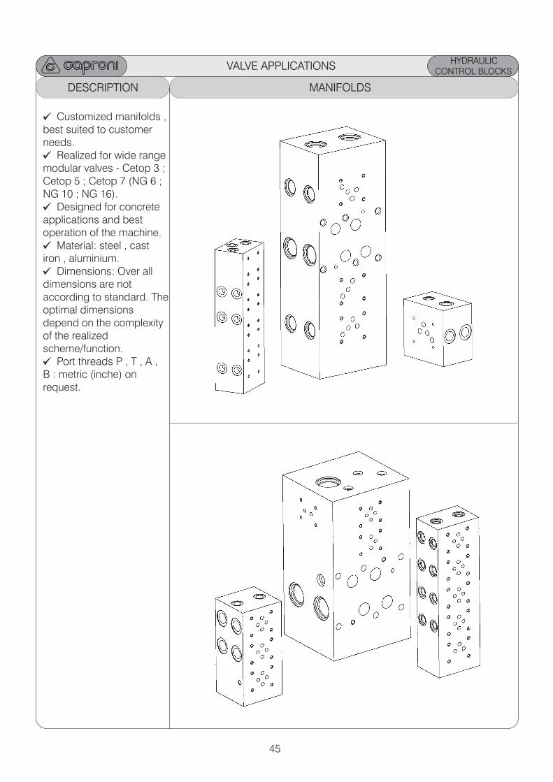
DESCRIPTION MANIFOLDS
Customized manifolds ,best suited to customerneeds.
Realized for wide rangemodular valves - Cetop 3 ;Cetop 5 ; Cetop 7 (NG 6 ;NG 10 ; NG 16).
Designed for concreteapplications and bestoperation of the machine.
Material: steel , cast iron , aluminium.
Dimensions: Over alldimensions are notaccording to standard. Theoptimal dimensions depend on the complexityof the realized scheme/function.
Port threads P , T , A , B : metric (inche) onrequest.
46
HYDRAULIC CONTROL BLOCKS
VALVE APPLICATIONS
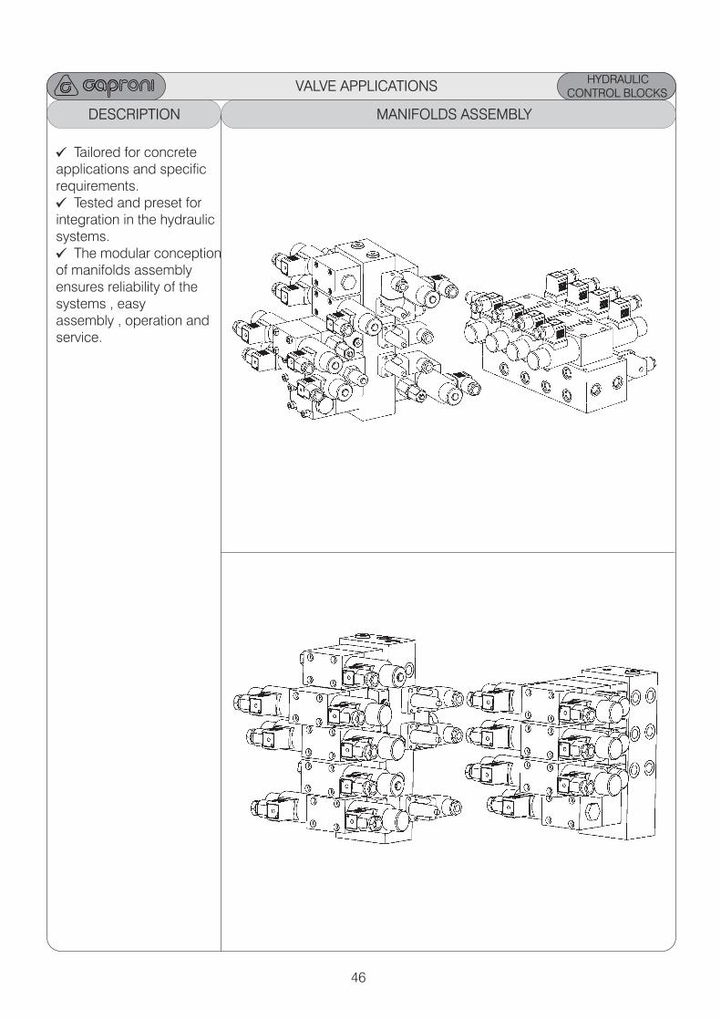
DESCRIPTION MANIFOLDS ASSEMBLY
Tailored for concreteapplications and specificrequirements.
Tested and preset forintegration in the hydraulicsystems.
The modular conceptionof manifolds assemblyensures reliability of the systems , easy assembly , operation andservice.

NOTES

NOTES
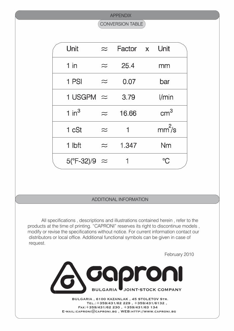
CONVERSION TABLE
APPENDIX
ADDITIONAL INFORMATION
All specifications , descriptions and illustrations contained herein , refer to the products at the time of printing. “CAPRONI” reserves its right to discontinue models ,modify or revise the specifications without notice. For current information contact our distributors or local office. Additional functional symbols can be given in case of request.
February 2010
BULGARIA JOINT-STOCK COMPANY
BULGARIA , 6100 KAZANLAK , 45 STOLETOV Str. Tel.:+359/431/62 229 , +359/431/6132 , Fax:+359/431/62 230 , +359/431/63 134 E-mail:[email protected] , WEB:http://www.caproni.bg