Embed Size (px)
Citation preview

S a f e t y R e l a y sS e r i e s U E 1 0 - 4 8
PR
OD
UC
T
CA
TA
LO
GU
E
1/
20
02
SICK © • Industrial Safety Systems • Germany • All rights reserved • 8 009 607/30-03-022
For technical details please unfold

SICK © • Industrial Safety Systems • Germany • All rights reserved • 8 009 607/30-03-02
Symbols used
UE 10 – UE 48 Safety Relays
Technical Details
Enclosure
75,5
12
3
96
61
,2
93,5
71,5 22,5
76,5
55,5
90
52
,5
75
3,8
120,5
107
für Hutschiene EN 50 022für Hutschiene EN 50 022
3,8
120,5
107
52
,5
75
45
3
Mechanical Safety Switches
Emergency Stop
Automatic Reset
Manual Reset
Safety Scanner
Safety Light Curtain
1 Normally closed ( NC)
Input
1 Normally open (NO)
Input
Mechanical locking,
electromagnetic release
(only for UE 44)
Electrical locking
(only for UE 45)
Function Modules
Type of Reset
Enclosure A Enclosure B Enclosure C
for mounting rail EN 50 022for mounting rail EN 50 022

8 009 607/30-02-02 • All rights reserved • Germany • Industrial Safety Systems • © SICK 4
8 009 607/30-02-02 • All rights reserved • Germany • Industrial Safety Systems • © SICK
Safety Relays UE 10 - UE 48
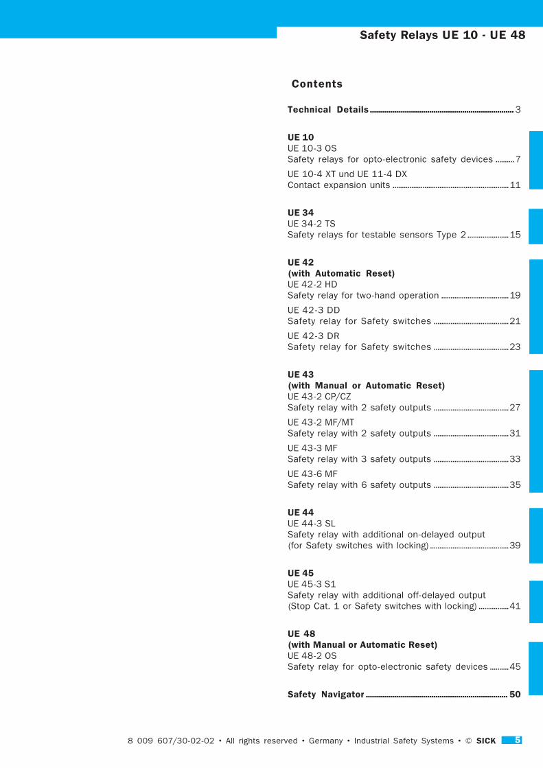
Contents
Technical Details ...................................................................... 3
UE 10UE 10-3 OS
Safety relays for opto-electronic safety devices .......... 7
UE 10-4 XT und UE 11-4 DX
Contact expansion units ..............................................................11
UE 34UE 34-2 TS
Safety relays for testable sensors Type 2 ......................15
UE 42(with Automatic Reset)UE 42-2 HD
Safety relay for two-hand operation ....................................19
UE 42-3 DD
Safety relay for Safety switches ........................................21
UE 42-3 DR
Safety relay for Safety switches ........................................23
UE 43(with Manual or Automatic Reset)UE 43-2 CP/CZ
Safety relay with 2 safety outputs ........................................27
UE 43-2 MF/MT
Safety relay with 2 safety outputs ........................................31
UE 43-3 MF
Safety relay with 3 safety outputs ........................................33
UE 43-6 MF
Safety relay with 6 safety outputs ........................................35
UE 44UE 44-3 SL
Safety relay with additional on-delayed output
(for Safety switches with locking) ..........................................39
UE 45UE 45-3 S1
Safety relay with additional off-delayed output
(Stop Cat. 1 or Safety switches with locking) ................41
UE 48(with Manual or Automatic Reset)UE 48-2 OS
Safety relay for opto-electronic safety devices ..........45
Safety Navigator ..................................................................... 50
5

SICK © • Industrial Safety Systems • Germany • All rights reserved • 8 009 607/30-03-02
Safety Relays UE 10 - UE 48
Machines and systems require numerous control
elements. This catalogue provides information about
Safety Relays in the UE series supplied by SICK.
These units are, in fact, Universal Equipments:
They save the designer
work and are simple to
incorporate. In addition
they are well tried and
tested and covered by all
relevant licences and
approvals. Furthermore,
they require little space
due to their compact
Standard enclosure.
The product programme is
just as versatile as the
fields of application. On the
penultimate page of this
catalogue is a table depic-
ting various features and
associated devices.
Many units have aExternal Device Monitoring (EDM)In virtually all cases, the Safety Relays have the
function external device monitoring. By using this, the
relay on the machine or system, connected to the UE,
is monitored – if, for example, the contacts weld or
melt.
All units – with one exception – are activeOnly the UE 10-3 OS Safety Relay is passive (in other
words, it requires no integral electrical power supply).
This unit is used as a converter, converting solid state
technology of opto-electronic safety devices to a volt
free state for relay technology.
Increasing the number of outputsOn many units (basic standard units) an add-on unit
(UE 10-4 XT or UE 11-4 DX) can be connected to
increase the quantity of switching outputs for these
standard units.
Automatic ResetMany of the units provide the choice of selecting
automatic or manual resetting. In the case of automatic
resetting, the output contacts are immediately
triggered (activated) upon removing the causes for
shutting down of the system.
UE Safety Relays – secure connecting links to ancillary equipment
Manual ResetIn the case of manual resetting, the output contacts
are only activated following removal of the causes for
shut down and after the reset button has been
operated.
Using the EmergencyStop functionSafety relays for emer-
gency stop applications
expect normally closed
input.
For movable guardsMany safety devices are
suitable for connection to
Safety switches – e.g.
with movable guards.
For testable sensors(Type 2)Testable sensors can be
connected to UE 34-2 TS
Safety Relays. Conse-
quently, cyclic testing is feasible.
Two-hand operationThe UE 42 HD safety relay allows the connection of a
two-hand switch – each having a normally open and a
nomally closed contact.
Pressure mat operationThe UE 43-2 MT Safety Relay is used for monitoring
short circuiting pressure mats (in 4-wire technology).
Monitoring of synchronisation timeMost units have a synchronisation time monitoring
system: It controls the brief period of time in which
the two input circuits are closed (e.g. for switches on
safety doors). This function is only accomplished with
the execution of a given sequence (with channel 1
preceding channel 2).
Simultaneous monitoringUnits having a simultaneous monitoring facility control
the closing times of both input circuits. With this the
two circuits are closed within a certain time span (UE
42-2 HD, UE 42-3 DR and UE 42-3 DD).
UE Safety Relays resolve any interface problems
6
8 009 607/30-02-02 • All rights reserved • Germany • Industrial Safety Systems • © SICK 7
Safety Relays UE 10-3 OS range
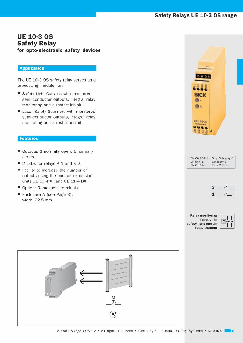
Application
The UE 10-3 OS safety relay serves as a
processing module for:
� Safety Light Curtains with monitored
semi-conductor outputs, integral relay
monitoring and a restart inhibit
� Laser Safety Scanners with monitored
semi-conductor outputs, integral relay
monitoring and a restart inhibit
Features
� Outputs: 3 normally open, 1 normally
closed
� 2 LEDs for relays K 1 and K 2
� Facility to increase the number of
outputs using the contact expansion
units UE 10-4 XT and UE 11-4 DX
� Option: Removable terminals
� Enclosure A (see Page 3),
width: 22.5 mm
UE 10-3 OSSafety Relayfor opto-electronic safety devices
<
8 009 607/30-03-02 • All rights reserved • Germany • Industrial Safety Systems • © SICK 7
3
1
Relay monitoringfunction in
safety light curtainresp. scanner
EN 60 204-1 Stop Category 0
EN 954-1 Category 2
EN 61 496 Type 2, 3, 4

8 SICK © • Industrial Safety Systems • Germany • All rights reserved • 8 009 607/30-03-02
Function
The two outputs from the safety sensors (e. g. C 4000
Light Curtain) are connected to the UE 10-3 OS.
If the sensors are active (not triggered), the relays K 1
and K 2 are switched to an active (energised) mode
(the LEDs for both relays illuminate):
The 3 electrical output contacts are closed and the
signal output contact is in an open mode. The relay
monitor of the OSSD units is to be wired with Y 1 and
Y 2.
In triggering the safety device, relays K 1 and K 2 de-
energise (inactive): The output contacts are open, and
the signal contact is closed.
If a restart inhibit is needed, then this is to be
installed in the sensor, for example in the C 4000.
External Device Monitoring (EDM)If external device monitoring is needed, then this should
be installed in the sensor, for example in the
C 4000, a pair of normally closed contacts in the
UE 10-3 OS is, however, part of this relay monitoring
(Y 1 - Y 2).
The UE-10-3 OS 2 unit has screw terminals,
the UE-10-3 OS 3 removable plug block terminals.
Safety Relays UE 10-3 OS range
Circuit Wiring Diagram UE 10-3 OS
K
K
B1 B2
14 24 34 B4
B3 B4
CH
CH
13 23 Y1 Y2 B3B1
41 42
33
B2
24
2313
14
Y1
Y2
41
42 34
33 Y1A1 51Y2
2313 6133
Steckblockklemme
Geräteanschluss
Steckblockklemme
Geräteanschluss
1.21.1 1.41.3
Geräteanschluss
Steckblockklemme
Geräteanschluss
Steckblockklemme
3.23.1 3.43.3
4.24.1 4.44.3
2414 6234
2.22.1 2.42.3
4443 A252
Plug-in screw terminal blocks
Screw terminals
Plug-in screw terminal blocks
Screw terminals
Screw terminals
Plug-in screw terminal blocks
Screw terminals
Plug-in screw terminal blocks

8 009 607/30-02-02 • All rights reserved • Germany • Industrial Safety Systems • © SICK 9
Safety Relays UE 10-3 OS range
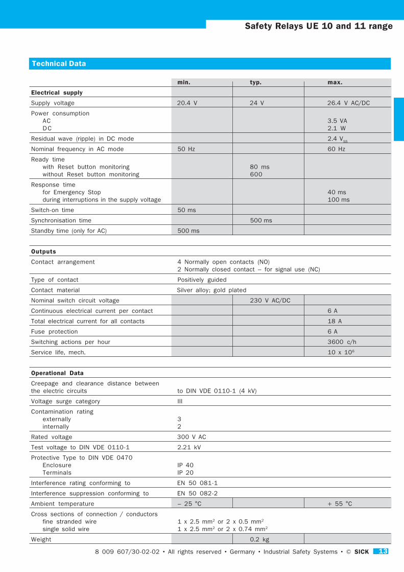
Technical Data
min. typ. max.
Electrical supply no electrical supply
Response time 25 ms
Switch-on time 50 ms
Outputs
Contact arrangement 3 Normally open contacts (NO)
1 Normally closed contact – for signal use (NC)
Type of contact Positively guided
Contact material Silver alloy; gold plated
Nominal switch circuit voltage 230 V AC/DC
Continuous electrical current per contact 6 A
Total electrical current for all contacts 18 A
Fuse protection 6 A
Switching actions per hour 3600 c/h
Service life, mech. 10 x 106
Operational Data
Creepage and clearance distance between
the electric circuits to DIN VDE 0110-1 (4 kV)
Voltage surge category III
Contamination rating
externally 3
internally 2
Rated voltage 300 V AC
Test voltage to DIN VDE 0110-1 2.21 kV
Protective Type to DIN VDE 0470
Enclosure IP 40
Terminals IP 20
Interference rating conforming to EN 50 081-1
Interference suppression conforming to EN 50 082-2
Ambient temperature – 25 °C + 55 °C
Cross sections of connection/conductors
fine stranded wire 1 x 2.5 mm2 or 2 x 0.5 mm2
single solid wire 1 x 2.5 mm2 or 2 x 0.74 mm2
Weight 0.2 kg

10 SICK © • Industrial Safety Systems • Germany • All rights reserved • 8 009 607/30-03-02
Order List for UE 10
Type Outputs Connections No electrical supply Part No.
Direct Plug-in block terminals
UE 10 - 3 OS 2 D 0 6 024 917
UE 10 - 3 OS 3 D 0 6 024 918
Safety Relays UE 10-3 OS range

8 009 607/30-02-02 • All rights reserved • Germany • Industrial Safety Systems • © SICK 11
UE 10-4 XT and UE 11-4 DXContact expansion units
Application
The contact expansion units UE 10-4 XT
and UE 11-4 DX are used for
� Increasing the number of normally
open contacts of a basic unit
� UE 11-4 DX with release time delay
function
Features
� Feedback circuit for external device
monitoring function
� Outputs: 4 normally open, 2 normally
closed
� 2 LEDs for relays K 1 and K 2
� Enclosure A (see Page 3),
width: 22.5 mm
z. B. UE 43 - 3 MFBasis-Gerät
UE 10 - 4 EXUE 11 - 4 DX
8 009 607/30-03-02 • All rights reserved • Germany • Industrial Safety Systems • © SICK 11
Safety Relays UE 10 and 11 range
2
4
EN 60 204-1 As basic unit
EN 954-1 Category 1
Relay monitoring
function
in Basic Unit
e. g.UE 43-3 MFBasic Unit
UE 10-4 EXUE 10-4 DXContact expansion unit

12 SICK © • Industrial Safety Systems • Germany • All rights reserved • 8 009 607/30-03-02
Function
The supply voltage of the contact expansion unit is
wired via an normally open output of a basic unit.
After applying the supply voltage to terminals A 1 and
A 2, the relays K 1 and K 2 are switched to an
energised state (the LEDs for both relays illuminate):
The 4 normally open contacts are closed and the
signal circuit (for external device monitoring) is open.
If the normally open contact(s) of the basic unit are
open with opened external device monitoring, (e. g. by
activating the Emergency Stop switch), the relays K 1
and K 2 de-energise: The normally open contacts
open, and the signal circuit closes.
The external device monitoring Y 1 - Y 2 prevent
restarting/re-energising of basic unit when K 1 and K 2
do not de-energise.
The function of UE 11-4 DX ...... corresponds to that of UE 10-4 XT. However, the
unit additionally has (depending upon the type) fixed
off-delay times: 0.5 s, 1 s, 2 s and 3 s. They are
achieved by means of capacitors, so that even in the
event of a power failure the release delay in each
case is fully accomplished. The delay cannot be
prematurely cancelled. Only after the cyclic operation
do the relays K 1 and K 2 return to their nominal rest
position.
Stop Category 1 is, as a rule, effected with the use of
release delayed units.
The units ... XT 2 and ... DX 2 have screw terminals,
the units ... XT 3 and ... DX 3 have removable plug-in
block terminals.
13 23 33 61
A1 Y1 Y2 S1
43 44 52 A2
14 24 34 62
Y1 13 23 33 43 51 61
Y2 14 24 34 44 52 62
A1 A2
K2
K1
A1 A2
17 27 37 65
A1 Y1 Y2 55
47 48 56 A2
18 28 38 66
K2
K1
Y2 18 28 38 48 56 66
Y1 17 27 37 47 55 65
UE-10-4 XT
UE-11-4 DX
Steckblockklemme
Geräteanschluss
Steckblockklemme
Geräteanschluss
Geräteanschluss
Steckblockklemme
Geräteanschluss
Steckblockklemme
Steckblockklemme
Geräteanschluss
Steckblockklemme
Geräteanschluss
Geräteanschluss
Steckblockklemme
Geräteanschluss
Steckblockklemme
3.1 3.2 3.3 3.4
13 23 33 61
1.1 1.2 1.3 1.4
A1 Y1 Y2 51
43 44 52 A2
2.1 2.2 2.3 2.4
14 24 34 62
4.1 4.2 4.3 4.4
3.1 3.2 3.3 3.4
17 27 37 65
1.1 1.2 1.3 1.4
A1 Y1 Y2 55
47 48 56 A2
2.1 2.2 2.3 2.4
18 28 38 66
4.1 4.2 4.3 4.4
Circuit Wiring Diagram
Safety Relays UE 10/11 range
Plug-in screw terminal blocks
Screw terminals
Plug-in screw terminal blocks
Screw terminals
Screw terminals
Plug-in screw terminal blocks
Screw terminals
Plug-in screw terminal blocks
Plug-in screw terminal blocks
Screw terminals
Plug-in screw terminal blocks
Screw terminals
Screw terminals
Plug-in screw terminal blocks
Screw terminals
Plug-in screw terminal blocks
8 009 607/30-02-02 • All rights reserved • Germany • Industrial Safety Systems • © SICK 13
Safety Relays UE 10 and 11 range
Technical Data
min. typ. max.
Electrical supply
Supply voltage 20.4 V 24 V 26.4 V AC/DC
Power consumption
AC 3.5 VA
D C 2.1 W
Residual wave (ripple) in DC mode 2.4 VSS
Nominal frequency in AC mode 50 Hz 60 Hz
Ready time
with Reset button monitoring 80 ms
without Reset button monitoring 600
Response time
for Emergency Stop 40 ms
during interruptions in the supply voltage 100 ms
Switch-on time 50 ms
Synchronisation time 500 ms
Standby time (only for AC) 500 ms
Outputs
Contact arrangement 4 Normally open contacts (NO)
2 Normally closed contact – for signal use (NC)
Type of contact Positively guided
Contact material Silver alloy; gold plated
Nominal switch circuit voltage 230 V AC/DC
Continuous electrical current per contact 6 A
Total electrical current for all contacts 18 A
Fuse protection 6 A
Switching actions per hour 3600 c/h
Service life, mech. 10 x 106
Operational Data
Creepage and clearance distance between
the electric circuits to DIN VDE 0110-1 (4 kV)
Voltage surge category III
Contamination rating
externally 3
internally 2
Rated voltage 300 V AC
Test voltage to DIN VDE 0110-1 2.21 kV
Protective Type to DIN VDE 0470
Enclosure IP 40
Terminals IP 20
Interference rating conforming to EN 50 081-1
Interference suppression conforming to EN 50 082-2
Ambient temperature – 25 °C + 55 °C
Cross sections of connection / conductors
fine stranded wire 1 x 2.5 mm2 or 2 x 0.5 mm2
single solid wire 1 x 2.5 mm2 or 2 x 0.74 mm2
Weight 0.2 kg

14 SICK © • Industrial Safety Systems • Germany • All rights reserved • 8 009 607/30-03-02
Safety Relays UE 10/11 range
Order List for UE 10
Type Outputs Connections Electrical supply Part No.
Direct Removable terminals 24 V AC/DC
UE 10 - 4 X T 2 D 2 6 024 919
UE 10 - 4 X T 3 D 2 6 024 920
Order List for UE 11 (with delay facility)
Type Outputs Connections Electrical supply Delay Part No.
Direct Removable terminals 24 V DC s
UE 11 - 4 D X 2 D 3 0.5 6 024 921
UE 11 - 4 D X 2 D 3 1 6 024 922
UE 11 - 4 D X 2 D 3 2 6 024 923
UE 11 - 4 D X 2 D 3 3 6 024 924
UE 11 - 4 D X 3 D 3 0.5 6 024 925
UE 11 - 4 D X 3 D 3 1 6 024 926
UE 11 - 4 D X 3 D 3 2 6 024 927
UE 11 - 4 D X 3 D 3 3 6 024 928

8 009 607/30-02-02 • All rights reserved • Germany • Industrial Safety Systems • © SICK 15
Safety Relays UE 34 range
UE 34-2 TS Safety Relayfor testable Type 2 sensors
Application
The UE 34 safety relay is used as a
processing module for
� Testable Type 2 sensors
� Control systems in accordance with EN
60 204 respectively EN 954-1
(Category 3)
Features
� Dual-channel actuation system having
- Cross circuit short detection
- Override facility
- Cyclic testing
- Time monitoring
� Outputs: 2 Normally open, 1 Normally
closed
� Feedback connection for monitoring
function of the sensor
� 4 LEDs for electrical supply, standby,
protected zone free and override
� Manual Restart
� Automatic Restart
� Facility to increase the number of
outputs using the contact expansion
units UE 10-4 XT and UE 11-4 DX
� Enclosure A (see Page 3),
width: 22.5 mm
8 009 607/30-03-02 • All rights reserved • Germany • Industrial Safety Systems • © SICK 15
2
1
EDM
EN 60 204-1 Stop Category 0
EN 954-1 Category 3

16 SICK © • Industrial Safety Systems • Germany • All rights reserved • 8 009 607/30-03-02
Safety Relays UE 34 range
Function
After applying the supply voltage to the terminals A 1 -
A 2 a self diagnostic test is carried out. If this is
satisfactory, the unit is in its standby mode, and the
LED OUTPUT illuminates yellow. If the self diagnostic
test is unsatisfactory, then this leads to the program
being aborted and restarted. Further procedure is
dependent upon the results of self diagnostic testing,
the operating mode set and external wiring / selected
mode.
The unit compares the input signals (from the sensors)
Y 12 and Y 13 with the output signals to Y 41 and
Y 42. The LED INPUT indicates harmonisation.
Respective of the selected function, the output
contacts of the UE 34 close either automatically when
the inputs are energised (operation without restart
inhibit) or remain open (non-energised), until the reset
button is activated and released again (restart inhibit).
As an electrical release circuit, there are 2 normally
open contacts (NO) and 1 normally closed contact (NC)
available (LED OUTPUT yellow).
Modes of operationThe following modes of operation can be selected by
means of a function selector switch on the back face
of the unit (no longer accessible when installed):
� Pulse direction testing mode (pos./neg. pulse)
� Manual or Automatic reset mode
OverrideThe override can be activated by way of the input X 1.
As a result, the unit can be overriden (LED OVR
illuminates yellow). Activation is effected by means of
the output circuit of an independent unit, which results
in that relays K 1 and K 2 do not de-energise during
override if the sensors are temporarily inactive.
Manual ResetThe Reset button is connected to the terminals S 33 -
S 34. Start after activation and release of the reset
switch.
Automatic ResetBridge connection between terminals S 33 and S 34.
The UE 34-2 TS 2 unit has screw terminals,
the UE 34-2 TS 3 unit has removable plug-in block
terminals.
Circuit Wiring Diagram UE 34-2 TS
2313
S3A1
S2S21
S1114
31 24
S3S3
A2S31
32 S12
K1
K2
-- +
13A1 A2
14
3123
3224
S31
K2
S2
-
S34+
S35+
S12
K1
CONTROL-
LOGIC
+ +
S21 S11 S3
LED Function
SUPPLY Electrical supply on,
READY unit in standby mode
OSSD Protected zone free
(Output circuit closed)
OVR Override

8 009 607/30-02-02 • All rights reserved • Germany • Industrial Safety Systems • © SICK 17
Safety Relays UE 34 range
Technical Data
min. typ. max.
Electrical supply
Supply voltage 20.4 V 24 V 26.4 V AC/DC
Power consumption
AC 3.5 VA
D C 2.1 W
Residual wave (ripple) in DC mode 2.4 VSS
Nominal frequency in AC mode 50 Hz 60 Hz
Ready time
with Reset monitoring 80 ms
without Reset monitoring 600
Response time
for Emergency Stop 40 ms
during interruptions in the supply voltage 100 ms
Switch-on time 50 ms
Synchronisation time 500 ms
Standby time (only for AC) 500 ms
Outputs
Contact arrangement 2 Normally open contacts (NO)
1 Normally closed contact – for signal use (NC)
Type of contact Positively guided
Contact material Silver alloy; gold plated
Nominal switch circuit voltage 230 V AC/DC
Continuous electrical current per contact 6 A
Total electrical current for all contacts 18 A
Fuse protection 6 A
Switching actions per hour 3600 c/h
Service life, mech. 10 x 106
Operational Data
Creepage and clearance distance between
the electric circuits to DIN VDE 0110-1 (4 kV)
Voltage surge category III
Contamination rating
externally 3
internally 2
Rated voltage 300 V AC
Test voltage to DIN VDE 0110-1 2.21 kV
Protective Type to DIN VDE 0470
Enclosure IP 40
Terminals IP 20
Interference rating conforming to EN 50 081-1
Interference suppression conforming to EN 50 082-2
Ambient temperature – 25 °C + 55 °C
Cross sections of connection / conductors
fine stranded wire 1 x 2.5 mm2 or 2 x 0.5 mm2
single solid wire 1 x 2.5 mm2 or 2 x 0.74 mm2
Weight 0.2 kg

18 SICK © • Industrial Safety Systems • Germany • All rights reserved • 8 009 607/30-03-02
Order List for UE 34
Type Outputs Connections Electrical supply Part No.
Direct Removable terminals 24 V DC
UE 34 - 2 T S 2 D 3 6 024 929
UE 34 - 2 T S 3 D 3 6 024 930
Safety Relays UE 34 range

8 009 607/30-02-02 • All rights reserved • Germany • Industrial Safety Systems • © SICK 19
Safety Relays UE 42 HD range
UE 42-2 HD Safety Relayfor two hand operation
Application
The UE 42-2 HD safety relay is used as a
monitoring module for:
� Two hand controls with Type III C
requirements to EN 574 and to EN
954-1, Category 4
� Two hand control switches each with
1 NC/NO contacts
Features
� Cross circuit short detection
� Outputs: 2 normally open contacts,
1 normally closed contact
� 3 LEDs for supply voltage, relay K 1
and relay K 2
� Automatic Restart
� Facility to increase the number of
outputs using the contact expansion
units UE 10-4 XT and UE 11-4 DX
� Enclosure A (see Page 3),
width: 22.5 mm
8 009 607/30-03-02 • All rights reserved • Germany • Industrial Safety Systems • © SICK 19
1
2
EN 954-1 Category 4
EN 574 Type III C
EDM

20 SICK © • Industrial Safety Systems • Germany • All rights reserved • 8 009 607/30-03-02
Safety Relays UE 42 HD range
13 23 33 61
A1 Y1 Y2 S1
A1 A2 Y1 Y2 Y11 Y12 Y14 13 23 31
Y21 Y22 Y24 14 24 32
K1
K1
14 24 32 A2
Y11 Y21 Y1 Y2
Feedback
Channel 2
Channel 1
Control-Logic
L+ (L1)
S1 S2
Feed Back Channel 1
Channel 2
Control-LogicK1
K2
Y12 Y14 Y22 Y24 A1 13 23 31
Y11 Y21 Y1 Y2 14 24 32 A2
K3K4
Y21 Y22 Y24
A1 A2 Y1 Y2 Y11 Y12 Y14
Function
The UE 42-2 HD is self monitoring and conforms to
EN 574 Type III C. The prerequisite for release of the
outputs is that the two inputs (e. g. through a two hand
operated control start) are activated within 0.5 s.
After applying the supply voltage to the terminals A 1 -
A 2, the LED illuminates for indicating the presence of
electrical voltage. Simultaneous activation of the two
start buttons S 1 and S 2 closes the two output
circuits. Release – even by just one of the switches –
opens the circuits.
A restart is only possible if both switches have
returned to their nominal start position (in the case of
two hand operated switches: when both have been
released) and the feedback circuit is closed. The
contacts of the contactor monitoring (Y 1 - Y 2) may
only open after operating the switches, otherwise the
relays remain inactive. LEDs indicate the switching
status of the relays.
External Device Monitoring (EDM)The UE 42 takes over the external device monitoring.
The normally closed contacts of the external relays are
connected to terminals Y 1 - Y 2, wired in series.
Automatic ResetThe UE 42-2 only has Automatic Reset, effected by
means of the external device monitoring at terminals
Y 1 - Y 2.
Cross circuit short detectionWhen operating in the dual-channel mode, the unit
monitors the input circuits for cross circuit shorts or
short circuiting to earth.
Simultaneous time monitoringFor higher levels of safety, it is possible to monitor
the closing times of both inputs: The two switches are
to be activated within 0.5 s.
The UE 42-2 HD 2 has screw terminals,
the UE 42-2 HD 3 has removable plug-in block
terminals.
Circuit Wiring Diagram UE 42-2 HD
Two hand control with Automatic Reset
8 009 607/30-02-02 • All rights reserved • Germany • Industrial Safety Systems • © SICK 21
Safety Relays UE 42 DD range
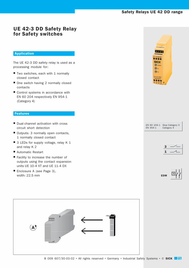
UE 42-3 DD Safety Relayfor Safety switches
Application
The UE 42-3 DD safety relay is used as a
processing module for:
� Two switches, each with 1 normally
closed contact
� One switch having 2 normally closed
contacts
� Control systems in accordance with
EN 60 204 respectively EN 954-1
(Category 4)
Features
� Dual-channel activation with cross
circuit short detection
� Outputs: 3 normally open contacts,
1 normally closed contact
� 3 LEDs for supply voltage, relay K 1
and relay K 2
� Automatic Restart
� Facility to increase the number of
outputs using the contact expansion
units UE 10-4 XT and UE 11-4 DX
� Enclosure A (see Page 3),
width: 22.5 mm
8 009 607/30-03-02 • All rights reserved • Germany • Industrial Safety Systems • © SICK 21
3
1
EDM
EN 60 204-1 Stop Category 0
EN 954-1 Category 4

22 SICK © • Industrial Safety Systems • Germany • All rights reserved • 8 009 607/30-03-0222
Safety Relays UE 42 DD range
Function
After applying the supply voltage to terminals A 1 - A 2
the LED illuminates to indicate the presence of
electrical voltage. By closing the input circuit (e. g.
closing the movable guard) the outputs are activated:
The 3 normally open output circuits close and the
signal circuit (normally closed) opens.
Activation of the relay interrupts the electrical supply
of relays K 1 and K 2. The normally open contacts
open and the signal normally closed circuit closes.
External Device Monitoring (EDM)The UE 42 takes over external device monitoring. The
normally closed contacts of the external relays are
connected to terminals Y 1 - Y 2, wired in series.
Automatic ResetThe UE 42-3 has an Automatic Reset, effected by
means of the external device monitoring at terminals
Y 1 - Y 2.
Cross circuit short detectionWhen operating in the dual-channel mode, the unit
monitors the input circuits for cross circuit shorts or
short circuiting to earth.
Simultaneous monitoringFor higher levels of safety it is possible to monitor
the closing times of both inputs: The two switches
(2 normally open contacts) are to be activated within
1.5 s. In so doing, the sequence is irrelevant.
The UE 42-3 DD 2 has screw terminals,
the UE 42-3 HD 3 has removable plug-in block
terminals.
+
-
13 23 S13 S14
A1 41 S23 S24
A1 A2 Y1 Y2 S13 S14 13 23 33 41
S23 S24 14 24 34 42
K1
K2
42 Y1 Y2 A2
Feedback
Channel 2
Channel 1
14 24 33 34
Control-Logic
3.1 3.2 3.3 3.4
13 23 S13 S14
1.1 1.2 1.3 1.4
A1 41 S23 S24
42 Y1 Y2 A2
2.1 2.2 2.3 2.4
14 24 33 34
4.1 4.2 4.3 4.4
+
-
L+ (L1)
Schutztür
offen
M (N)
13 23 S13 S14 A1 41 S23 S24
14 24 33 34
S23 S24 42
A1 A2 Y1 Y2 S13 S14 41
S 2
S 1
Feedback
Channel 2
Channel 1
Control-LogicK1
K2
42 Y1 Y2 A2
= betätigt
Circuit Wiring Diagram UE 42-3 DD
Movable guard with Automatic Reset, without
external device monitoring
Plug-in screw terminal blocks
Screw terminals
Plug-in screw terminal blocks
Screw terminals
Screw terminals
Plug-in screw terminal blocks
Screw terminals
Plug-in screw terminal blocks
movable guard
open
= active

8 009 607/30-02-02 • All rights reserved • Germany • Industrial Safety Systems • © SICK 23
Safety Relays UE 42 DR range
UE 42-3 DR Safety Relayfor Safety switch
Application
The UE 42-3 DR safety relay is used as a
logic link for:
� A safety switch equipped with
1 normally closed / 1 normally open,
e. g. movable guard
� Control systems to EN 60 204
respectively EN 954-1 (Category 4)
Features
� Dual-channel activation with cross
circuit short detection
� Outputs: 3 normally open contacts,
1 normally closed contact
� 3 LEDs for supply voltage and relays
K 1 and K 2
� Automatic Reset
� Facility to increase the number of
outputs using the contact expansion
units UE 10-4 XT and UE 11-4 DX
� Enclosure A (see Page 3),
width: 22.5 mm
3
238 009 607/30-03-02 • All rights reserved • Germany • Industrial Safety Systems • © SICK
EDM
EN 60 204-1 Stop Category 0
EN 954-1 Category 4
1

24 SICK © • Industrial Safety Systems • Germany • All rights reserved • 8 009 607/30-03-0224
Function
After applying the supply voltage to terminals A 1 - A 2
the LED illuminates to indicate the presence of
electrical voltage. By closing the input circuit (e. g.
closing the safety door) the output is activated: The 3
normally open contacts close and the normally closed
contacts open.
Activation of the relay interrupts the electrical supply
of relays K 1 and K 2. The normally open contacts
open and the normally closed contact closes.
External Device Monitoring (EDM)The UE 42 takes over external devide monitoring. The
normally closed contacts of the external relays are
connected to terminals Y 1 - Y 2, wired in series.
Automatic ResetThe UE 42-3 has an Automatic Reset, effected by
means of external device monitoring at terminals Y 1 -
Y 2.
Cross circuit short detectionWhen operating in the dual-channel mode, the unit
monitors the input circuits for cross circuit shorts or
short circuiting to earth.
Simultaneous monitoringFor higher levels of safety it is possible to monitor
the closing times of both inputs: The two switches
(1 normally open contact / 1 normally closed contact)
are to be activated within 300 s. In so doing, the
sequence is irrelevant.
The UE 42-3 DR 2 has screw terminals,
the UE 42-3 DR 3 has removable plug-in block
terminals.
Safety Relays UE 42 DR range
+
+
13 23 S13 S14
A1 41 S21 S22
A1 A2 Y1 Y2 S13 S14 13 23 33 41
S21 S22 14 24 34 42
K1
K2
42 Y1 Y2 A2
Feedback
Channel 2
Channel 1
14 24 33 34
Conrtol-Logic
Steckblockklemme
Geräteanschluss
Steckblockklemme
Geräteanschluss
Geräteanschluss
Steckblockklemme
Geräteanschluss
Steckblockklemme
3.1 3.2 3.3 3.4
13 23 S13 S14
1.1 1.2 1.3 1.4
A1 41 S21 S22
42 Y1 Y2 A2
2.1 2.2 2.3 2.4
14 24 33 34
4.1 4.2 4.3 4.4
+
+
42 Y1 Y2 A2
L+ (L1)Schutztür
offen
= betätigt
M (N)
13 23 S13 S14 A1 41 S21 S22
14 24 33 34
S21 S22 42
A1 A2 Y1 Y2 S13 S14 41
Feedback
Channel 2
Channel 1
Conrtol-LogicK1
K2
S1
S2
Circuit Wiring Diagram UE 42-3 DR
Movable guard with Automatic Reset, without
external device monitoring
Plug-in screw terminal blocks
Screw terminals
Plug-in screw terminal blocks
Screw terminals
Screw terminals
Plug-in screw terminal blocks
Screw terminals
Plug-in screw terminal blocks
movable guard
open
= active

8 009 607/30-02-02 • All rights reserved • Germany • Industrial Safety Systems • © SICK 25
Safety Relays UE 42 range
Technical Data
min. typ. max.
Electrical supply
Supply voltage 20.4 V 24 V 26.4 V AC/DC
Power consumption
AC 3.5 VA
D C 2.1 W
Residual wave (ripple) in DC mode 2.4 VSS
Nominal frequency in AC mode 50 Hz 60 Hz
Ready time
with Reset monitoring 80 ms
without Reset monitoring 600
Response time
for Emergency Stop 40 ms
during interruptions in the supply voltage 100 ms
Switch-on time 50 ms
Synchronisation time HD: 0.5 s
DD: 1.5 s, DR: 300 s
Standby time (only for AC) 500 ms
Outputs
Contact arrangement 3 (2) Normally open (NO) contacts DD, DR, (HD)
1 Normally closed (NC) contact – for signal use DD, DR, HD
Type of contact Positively guided
Contact material Silver alloy; gold plated
Nominal switch circuit voltage 230 V AC/DC
Continuous electrical current per contact 6 A
Total electrical current for all contacts 18 A
Fuse protection 6 A
Switching actions per hour 3600 c/h
Service life, mech. 10 x 106
Operational Data
Creepage and clearance distance between
the electric circuits to DIN VDE 0110-1 (4 kV)
Voltage surge category III
Contamination rating
externally 3
internally 2
Rated voltage 300 V AC
Test voltage to DIN VDE 0110-1 2.21 kV
Protective Type to DIN VDE 0470
Enclosure IP 40
Terminals IP 20
Interference rating conforming to EN 50 081-1
Interference suppression conforming to EN 50 082-2
Ambient temperature – 25 °C + 55 °C
Cross sections of connection/conductors
fine stranded wire 1 x 2.5 mm2 or 2 x 0.5 mm2
single solid wire 1 x 2.5 mm2 or 2 x 0.74 mm2
Weight 0.2 kg
26 SICK © • Industrial Safety Systems • Germany • All rights reserved • 8 009 607/30-03-02
Safety Relays UE 42 HD range
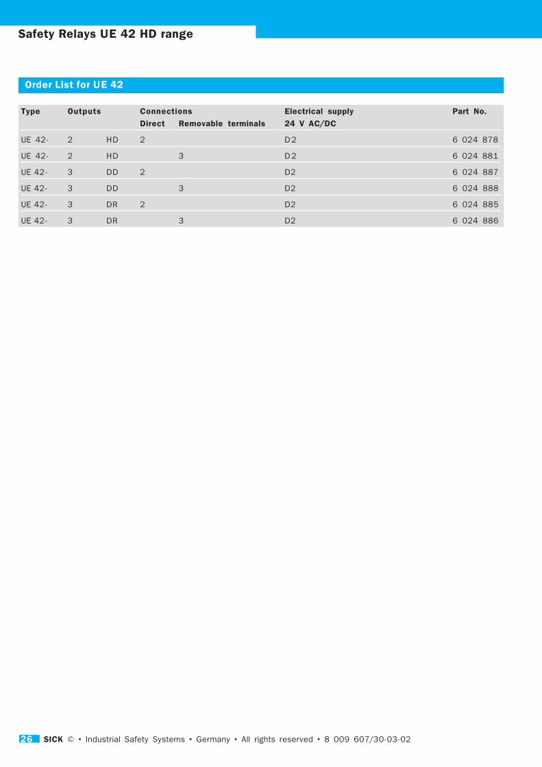
Order List for UE 42
Type Outputs Connections Electrical supply Part No.
Direct Removable terminals 24 V AC/DC
UE 42- 2 HD 2 D 2 6 024 878
UE 42- 2 HD 3 D 2 6 024 881
UE 42- 3 DD 2 D2 6 024 887
UE 42- 3 DD 3 D2 6 024 888
UE 42- 3 DR 2 D2 6 024 885
UE 42- 3 DR 3 D2 6 024 886
8 009 607/30-02-02 • All rights reserved • Germany • Industrial Safety Systems • © SICK 27
UE 43-2 CP and CZSafety RelaysManual or Automatic Reset
Application
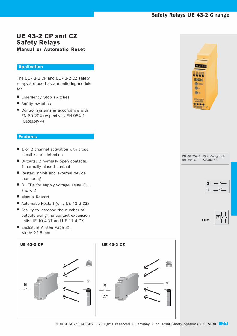
The UE 43-2 CP and UE 43-2 CZ safety
relays are used as a monitoring module
for
� Emergency Stop switches
� Safety switches
� Control systems in accordance with
EN 60 204 respectively EN 954-1
(Category 4)
Features
� 1 or 2 channel activation with cross
circuit short detection
� Outputs: 2 normally open contacts,
1 normally closed contact
� Restart inhibit and external device
monitoring
� 3 LEDs for supply voltage, relay K 1
and K 2
� Manual Restart
� Automatic Restart (only UE 43-2 CZ)
� Facility to increase the number of
outputs using the contact expansion
units UE 10-4 XT and UE 11-4 DX
� Enclosure A (see Page 3),
width: 22.5 mm
UE 43-2 CP UE 43-2 CZ
oror
8 009 607/30-03-02 • All rights reserved • Germany • Industrial Safety Systems • © SICK 27
Safety Relays UE 43-2 C range
2
1
EDM
EN 60 204-1 Stop Category 0
EN 954-1 Category 4
28 SICK © • Industrial Safety Systems • Germany • All rights reserved • 8 009 607/30-03-02
Safety Relays UE 43-2 C range
Function
After applying the supply voltage to terminals A 1 - A 2
the LED illuminates to indicate the presence of
electrical voltage. Release is effected as selected –
Automatically or by Manual Reset: The 2 normally open
output contacts close and the normally closed output
contact opens.
Activation of the relay interrupts the electrical supply
of relays K 1 and K 2. The normally closed circuits
open and the signal circuit closes.
Cross circuit short detectionWhen operating in the dual-channel mode, the unit
monitors the input circuits for cross circuit shorts or
short circuiting to earth.
UE 43-2 CPFor Manual Reset a button is connected to the
terminals S 33 - S 34.
Start after activation and release of the reset switch.
UE 43-2 CZFor Automatic Reset a link wire connection is to be
made to the terminals S 33 - S 34.
For Manual Reset a button is connected to the
terminals S 33 - S 34.
Start after activation of the reset switch.
External Device Monitoring (EDM)The UE 43-2 takes over external device monitoring.
The normally closed contacts of the external relays are
connected in series via the Reset circuit (S 33 - S 34).
Synchronisation time monitoringFor higher levels of safety, it is possible to monitor the
closing times of both inputs: The two switches are
activated within 0.5 s. If channel 2 closes prior to
channel 1, then synchronisation time monitoring will not
be activated.
The UE 43-2 CP 2 and UE 43-2 CZ 2 units have screw
terminals,
the UE 43-2 CP 3 and UE 43-2 CZ 3 units have
removable plug-in block terminals.
UE 43-2 CP: Dual-channel Emergency Stop application,
cross circuit shorts monitored, with Manual Reset and
Reset button monitoring
Reset
L+
(L1)
M
(N)
Not - Aus
+
S35
A1 S33 S34 S35 13 23 24 S12
14 S11 S12
S21 S11
--
+ +
+
K2
--
K1
CONTROL-
LOGIC
S11 A2
K1
K2
S22S21
S11
A1 A2 S34 S12
+
S12
S33
M
(N)
+
S36
A1 S11 S36 S34 13 23 24 S33
14 S11 S12
--
+
+
K2
--
K1
CONTROL-
LOGIC
S11 A2
K1
K2
S22S21
A1 A2 S34 S12
+
L+
(L1)
Not - Aus
S21 S11 S11 S11
S33
+
Reset
UE 43-2 CZ: Dual-channel Emergency Stop application,
cross circuit shorts monitored, with Manual Reset
S35+
2313
S33A1
S22S21
S1114
S1224
S35S34
A2S11
S12
K1
K2
-- +
13A1 A2
14
23
24
K2
S22--
S34+
S12
K1
CONTROL-
LOGIC
++
S21S11
S12
S11S33
S36+
2313
S11A1
S22S21
S1114
S3324
S34S36
A2S11
S12
K1
K2
-- +
13A1 A2
14
23
24
K2
S22--
S34+
S12
K1
CONTROL-
LOGIC
++
S21S11
S33
S11S11
UE 43-2 CP UE 43-2 CZ
AnschlkCircuit Wiring Diagram UE 43-2 C
Emergency stop
Emergency stop

8 009 607/30-02-02 • All rights reserved • Germany • Industrial Safety Systems • © SICK 29
Technical Data
min. typ. max.
Electrical supply
Supply voltage 20.4 V 24 V 26.4 V AC/DC
Power consumption
AC 3.5 VA
D C 2.1 W
Residual wave (ripple) in DC mode 2.4 VSS
Nominal frequency in AC mode 50 Hz 60 Hz
Ready time
with Reset monitoring 80 ms
without Reset monitoring 600 ms
Response time
for Emergency Stop 40 ms
during interruptions in the supply voltage 100 ms
Switch-on time 50 ms
Synchronisation time 500 ms
Standby time (only for AC) 500 ms
Outputs
Contact arrangement 2 Normally open contacts (NO)
1 Normally closed contact – for signal use (NC)
Type of contact Positively guided
Contact material Silver alloy; gold plated
Nominal switch circuit voltage 230 V AC/DC
Continuous electrical current per contact 6 A
Total electrical current for all contacts 18 A
Fuse protection 6 A
Switching actions per hour 3600 c/h
Service life, mech. 10 x 106
Operational Data
Creepage and clearance distance between
the electric circuits to DIN VDE 0110-1 (4 kV)
Voltage surge category III
Contamination rating
externally 3
internally 2
Rated voltage 300 V AC
Test voltage to DIN VDE 0110-1 2.21 kV
Protective Type to DIN VDE 0470
Enclosure IP 40
Terminals IP 20
Interference rating conforming to EN 50 081-1
Interference suppression conforming to EN 50 082-2
Ambient temperature – 25 °C + 55 °C
Cross sections of connection / conductors
fine stranded wire 1 x 2.5 mm2 or 2 x 0.5 mm2
single solid wire 1 x 2.5 mm2 or 2 x 0.74 mm2
Weight 0.2 kg
Safety Relays UE 43-2 C range

30 SICK © • Industrial Safety Systems • Germany • All rights reserved • 8 009 607/30-03-02
Order List for UE 43-2 C
Type Outputs Connections Electrical supply Part No.
Direct Removable terminals 24 V AC/DC
UE 43- 2 CP 2 D 2 6 024 889
UE 43- 2 CP 3 D 2 6 024 890
UE 43- 2 C Z 2 D 2 6 024 891
UE 43- 2 C Z 3 D 2 6 024 892
Safety Relays UE 43-2 C range
8 009 607/30-02-02 • All rights reserved • Germany • Industrial Safety Systems • © SICK 31
UE 43-2 MF and MTSafety RelaysManual or Automatic Reset
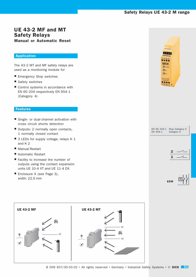
UE 43-2 MF UE 43-2 MT
Application
The 43-2 MT and MF safety relays are
used as a monitoring module for
� Emergency Stop switches
� Safety switches
� Control systems in accordance with
EN 60 204 respectively EN 954-1
(Category 4)
Features
� Single- or dual-channel activation with
cross circuit shorts detection
� Outputs: 2 normally open contacts,
1 normally closed contact
� 3 LEDs for supply voltage, relays K 1
and K 2
� Manual Restart
� Automatic Restart
� Facility to increase the number of
outputs using the contact expansion
units UE 10-4 XT and UE 11-4 DX
� Enclosure A (see Page 3),
width: 22.5 mm
Safety Relays UE 43-2 M range
8 009 607/30-03-02 • All rights reserved • Germany • Industrial Safety Systems • © SICK 31
or
or
or
2
1
EDM
EN 60 204-1 Stop Category 0
EN 954-1 Category 4

32 SICK © • Industrial Safety Systems • Germany • All rights reserved • 8 009 607/30-03-02
Function
After applying the supply voltage to terminals A 1 - A 2
the LED illuminates to indicate the presence of
electrical voltage. By closing the input circuit (e. g.
closing the movable guard) the output is activated:
The 2 normally open contacts close and the normally
closed circuit opens.
If the safety device is activated, the electrical supply
of the relays K 1 and K 2 is interrupted. The normally
open contacts open and normally closed contacts
close.
Manual ResetFor Manual Reset a button is connected to the
terminals S 33 - S 34.
Start after activation and release of the reset switch.
Automatic ResetFor Automatic Reset a link wire connection is made
between S 35 - S 12.
Cross circuit short detectionWhen operating in the dual-channel mode, the unit
monitors the input circuits for cross circuit shorts or
short circuiting to earth.
Simultaneous time monitoringFor higher levels of safety, it is possible to monitor
the closing times of both inputs: The two switches are
activated within 0.5 s. If channel 2 closes prior to
channel 1, then synchronisation time monitoring will
not be activated.
External Device Monitoring (EDM)The UE 43-2 takes over external device monitoring.
The normally closed contacts of the external relays are
connected in series via the Reset circuit (S 33 –
S 34).
The operation of UE 43-2 MT ...... corresponds to that of UE 43-2 MF, but pressure
mats or pressure switch rails can be connected using
4-wire technology (without monitoring resistance).
The UE 43-2 MF 2 and UE 43-2 MT 2 units have screw
terminals,
the UE 43-2 MF 3 and UE 43-2 MT 3 units have
removable plug-in block terminals.
Safety Relays UE 43-2 M range
-- +
K2--
+ +
K1
+ +
13 23 24 31
A1 S33 S34 S35
A1 A2
S21 S11 S33 S22 14 24 32
K1
K2
S21 S22 S31 A2
14 S11 S12 32
Control- Logic
Steckblockklemme
Geräteanschluss
Steckblockklemme
Geräteanschluss
Geräteanschluss
Steckblockklemme
Geräteanschluss
Steckblockklemme
3.1 3.2 3.3 3.4
13 23 24 31
1.1 1.2 1.3 1.4
A1 S33 S34 S35
S21 S22 S31 A2
2.1 2.2 2.3 2.4
14 S11 S12 32
4.1 4.2 4.3 4.4
S34 S35 S12 S31 13 23 31
--
+ + + +
--
K1
K2+
Schieschutzgitter
geschlossen
= betätigt
S1
L+ (L1)
M (N)
S2
A1 S33 S34 S35 13 23 24 31
A1 A2 S34 S35 S12 S31
Conrtol- Logic
K1 K2
S21 S11 S33
S21 S22 S31 A2 14 S11 S12 32
--
+ + + +
--
+
K1
K2Conrtol- Logic
L+ (L1)
Reset
S34 S35 S12 S31
A1 S33 S34 S35 13 23 24 31
A1 A2
S21 S11 S33S21 S22 S31 A2 14 S11 S12 32
K1 K2
M (N)
Schaltmatte
(unbetätigt)
Circuit Wiring Diagram UE 43-2 M
Movable guard with Automatic Reset, without external
device monitoring
Guarding with pressure mat and with Manual Reset,
without external device monitoring
Plug-in screw terminal blocks
Screw terminals
Plug-in screw terminal blocks
Screw terminals
Screw terminals
Plug-in screw terminal blocks
Screw terminals
Plug-in screw terminal blocks
mat
inactive
= active
movable guard
closed
8 009 607/30-02-02 • All rights reserved • Germany • Industrial Safety Systems • © SICK 33
Safety Relays UE 43-3 MF range
UE 43-3 MFSafety RelaysManual and Automatic Reset
??
Application
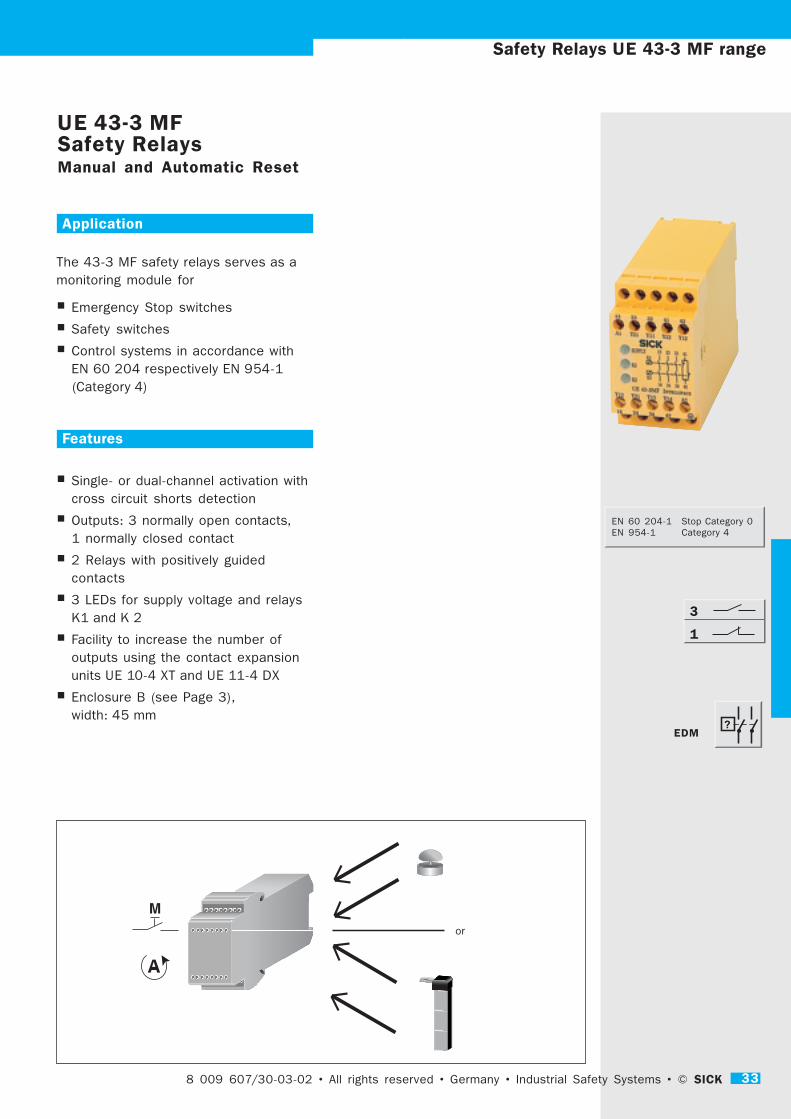
The 43-3 MF safety relays serves as a
monitoring module for
� Emergency Stop switches
� Safety switches
� Control systems in accordance with
EN 60 204 respectively EN 954-1
(Category 4)
Features
� Single- or dual-channel activation with
cross circuit shorts detection
� Outputs: 3 normally open contacts,
1 normally closed contact
� 2 Relays with positively guided
contacts
� 3 LEDs for supply voltage and relays
K1 and K 2
� Facility to increase the number of
outputs using the contact expansion
units UE 10-4 XT and UE 11-4 DX
� Enclosure B (see Page 3),
width: 45 mm
or
8 009 607/30-03-02 • All rights reserved • Germany • Industrial Safety Systems • © SICK 33
3
1
EDM
EN 60 204-1 Stop Category 0
EN 954-1 Category 4

34 SICK © • Industrial Safety Systems • Germany • All rights reserved • 8 009 607/30-03-02
+
+
--
+ + ++
--
13 23 33 41 42
Y13 Y14 Y12 Y12 Y31 13 23 33 41A1 A2
K1 K2 K3
Y11 Y21
Y12 Y31 Y13 Y14 A2
14 24 34 42
Y22 14 24 34 42 42
K2
K3
A1 Y21 Y11 Y22 Y12
+ --
++ + ++
= betätigt
L+ (L1)
M (N)
Schutztür
geschlossen
A1 Y21 Y11 Y22 Y12 13 23 33 41 42
Y13 Y14 Y12 Y12 Y31
K2
K3
A1 A2
Y11 Y21
Y12 Y31 Y13 Y14 14 24 34 42 A2
Reset
–Y22
K1 K2 K3
K1
K2
1
+ --
K2
K3
++ + ++
L+ (L1)
M (N)
K4
K5
A1 Y21 Y11 Y22 Y12 13 23 33 41 42
Y12 Y31 Y13 Y14 14 24 34 42 A2
A1 A2
Y11 Y21
Y13 Y14 Y12 Y12 Y31
= betätigt
Schutztür
geschlossen
–Y22
K1 K2 K3
K1
K2
Emergency Stop switching with Reset monitoring
Movable guard with Manual Reset
Movable guard with Automatic ResetCircuit Wiring Diagram UE 43-3 MF
+ --
++ + ++
L+ (L1)
M (N)
Not-Aus
A1 Y21 Y11 Y22 Y12 13 23 33 41 42
A1 A2Y13 Y14 Y12 Y12 Y31
K2
K3
K1 K2 K3
–Y22
Y12 Y31 Y13 Y14 14 24 34 42 A2
Reset
Y11 Y21
Function
After applying the supply voltage to terminals A 1 - A 2
the LED illuminates to indicate the presence of
electrical voltage. By closing the input circuit (e. g.
closing the movable guard) release is effected: The 3
normally open contacts close, and the normally closed
contact opens.
Activation of the switch or the Emergency Stop
interrupts the electrical supply of relays K 2 and K 3.
The normally open contacts open and the normally
closed contact closes.
Manual ResetFor Manual Reset a switch is connected to the
terminals Y 13 - Y 12 .
Start after activation and release of the reset switch.
Automatic ResetFor Automatic Reset, a link wire connection is made
between Y 14 - Y 12.
Cross circuit shorts detectionWhen operating in the dual-channel mode, the unit
monitors the input circuits for cross circuit shorts or
short circuiting to earth.
Synchronisation time monitoringFor higher levels of safety, it is possible to monitor
the closing times of both inputs: The two switches
(1 closing / 1 opening) are activated within 0.5 s. If
channel 2 closes prior to channel 1, then
synchronisation time monitoring is not activated.
External device monitoring (EDM)The UE 43-3 takes over external device monitoring via
the Reset circuit.
Safety Relays UE 43-3 MF range
= active
movable guard
closed
movable guard
closed
= active
Emergency stop

8 009 607/30-02-02 • All rights reserved • Germany • Industrial Safety Systems • © SICK 35
Safety Relays UE 43-6 MF range
UE 43-6 MFSafety RelaysManual and Automatic Reset
??
Application
The 43-6 MF safety relay is used as a
processing module for:
� Emergency Stop switches
� Safety switches
� Control systems in accordance with
EN 60 204 respectively EN 954-1
(Category 4)
Features
� Single or dual-channel activation with
cross circuit shorts detection
� Outputs: 6 normally open contacts,
4 normally closed contacts
� 3 LEDs for supply voltage and relays
K 2 and K 3
� Facility to increase the number of
outputs using the contact expansion
units UE 10-4 XT and UE 11-4 DX
� Enclosure C (see Page 3),
width: 90 mm
8 009 607/30-03-02 • All rights reserved • Germany • Industrial Safety Systems • © SICK 35
or
6
4
EDM
EN 60 204-1 Stop Category 0
EN 954-1 Category 4

36 SICK © • Industrial Safety Systems • Germany • All rights reserved • 8 009 607/30-03-02
13 23 33 43 53 63 71 81 91 01
72 82 9214 24 54 64 0234 44
K3
K2
S33
FEEDBACK
RESET
CONTROL- LOGIC
S34 Y1 S37
+
S12S11
+
Y3Y2Y1 S21
--
S22
K2
K3
S12S11 S33S34 Y1 Y2 Y3A1 S21 S22
++ --
A2
S37Y1 A2
A1
Reset
L1
Not-Aus
K 4
K 5
N
PE
( -- )(+)
K 4
K 5
13 23 33 43 53 63 71 81 91 01
72 82 9214 24 54 64 0234 44
K 3
K 2
S33
FEEDBACK
RESET
CONTROL- LOGIC
S34 Y1 S37
+
S12S11
+
Y3Y2Y1 S21
--
S22
K 2
K 3
S12S11 S33S34 Y1 Y2 Y3A1 S21 S22
++ --
A2
S37Y1 A2
A1
L1
K 4
K 5
Schutztür
geschlossenS 1
S 2
= betätigt
K 4
K 5
N
PE
( -- )(+)
14
13
24
23
34
33
44
43
54
53
64
63
72
71
82
81
92
91
02
01
FEEDBACK
RESET
CONTROL- LOGIC
K 2
K 3
A1A2 S34 Y1 S37S33
+
S12S11
+
Y3Y2Y1 S21
--
S22
A1 S11S12S21 S22S33S34 Y1 Y2 Y3
13 23 33 43 53 63 71 81 91 01
14 24 34 44 54 64 72 82 92 02
Y1 S37 A2
K 2
K 3
( -- )(+)
Function
After applying the supply voltage to terminals A 1 and
A 2, the LED for the electrical supply illuminates. By
closing the input circuit (e. g. closing the movable
guard) the output is activated: The 6 normally open
contacts close and the 4 normally closed contacts
open.
Activation of the relay interrupts the electrical supply
of relays K 2 and K 3. The normally open contacts
open and the normally closed contacts close.
Manual ResetFor Manual Reset a button is connected to the
terminals S 33 - S 34.
Start after activation and release of the reset switch.
Automatic ResetFor Automatic Reset a link wire connection is made
between S 34 - S 12.
Cross circuit shorts detectionWhen operating in the dual-channel mode, the unit
monitors the input circuits for cross circuit shorts or
short circuiting to earth.
Synchronisation time monitoringFor higher levels of safety, it is possible to monitor
the closing times of both inputs: The two switches (2
closing contacts) are activated within 0.5 s. If channel
2 closes prior to channel 1, then synchronisation time
monitoring will not be activated.
External Device Monitoring (EDM)The UE 43-6 takes over external device monitoring by
means of Y 1 - Y 2.
Circuit Wiring Diagram UE 43-6 MF
Safety Relays UE 43-6 MF range
Emergency Stop with Manual Reset, with external device
monitoring
Movable guard with Automatic Reset, with external
device monitoring
Emergency
stop
movable
guard closed
= active

8 009 607/30-02-02 • All rights reserved • Germany • Industrial Safety Systems • © SICK 37
Technical Data
min. typ. max.
Electrical supply
Supply voltage 20.4 V 24 V 26.4 V AC/DC
Power consumption
AC 3.5 VA
D C 2.1 W
Residual wave (ripple) in DC mode 2.4 VSS
Nominal frequency in AC mode 50 Hz 60 Hz
Ready time
with Reset monitoring 80 ms
without Reset monitoring 600
Response time
for Emergency Stop 40 ms
during interruptions in the supply voltage 100 ms
Switch-on time 50 ms
Synchronisation time 500 ms
Standby time (only for AC) 500 ms
Outputs
Contact arrangement (depending on type) 2, 3 or 6 Normally open contacts (NO) – UE 43-2, -3, -6
1 or 4 Normally closed contact – for signal use (NC)
Type of contact Positively guided
Contact material Silver alloy; gold plated
Nominal switch circuit voltage 230 V AC/DC
Continuous electrical current per contact 6 A
Total electrical current for all contacts 18 A
Fuse protection 6 A
Switching actions per hour 3600 c/h
Service life, mech. 10 x 106
Operational Data
Creepage and clearance distance between
the electric circuits to DIN VDE 0110-1 (4 kV)
Voltage surge category III
Protective Type to DIN VDE 0470
Enclosure 3
internally 2
Rated voltage 300 V AC
Test voltage to DIN VDE 0110-1 2.21 kV
Protective Type to DIN VDE 0470
Enclosure IP 40
Terminals IP 20
Interference rating conforming to EN 50 081-1
Interference suppression conforming to EN 50 082-2
Ambient temperature – 25 °C + 55 °C
Cross sections of connection / conductors
fine stranded wire 1 x 2.5 mm2 or 2 x 0.5 mm2
single solid wire 1 x 2.5 mm2 or 2 x 0.74 mm2
Weight 0.2 kg /0.36 kg /0.8 kg
Safety Relays UE 43-x MF range

38 SICK © • Industrial Safety Systems • Germany • All rights reserved • 8 009 607/30-03-02
Order List for UE 43- 2 MF, UE 43 - 3 MF/MT, UE 43-6 MF
Type Outputs Connections Electrical supply Part No.
Direct Removable terminals 24 V AC/DC 24 V DC 24 V AC 115 V AC 120 V AC 230 V AC
UE 43- 2 MF 2 D2 6 024 893
UE 43- 2 MF 3 D2 6 024 894
UE 43- 2 MT 2 D3 6 024 895
UE 43- 2 MT 3 D3 6 024 896
UE 43- 3 MF 2 D3 6 024 897
UE 43- 3 MF 2 A0 6 024 898
UE 43- 3 MF 2 A1 6 024 899
UE 43- 3 MF 2 A2 6 024 900
UE 43- 3 MF 2 A3 6 024 901
UE 43- 6 MF 2 D3 6 024 902
UE 43- 6 MF 2 A0 6 024 903
UE 43- 6 MF 2 A1 6 024 904
UE 43- 6 MF 2 A2 6 024 905
UE 43- 6 MF 2 A3 6 024 906
Safety Relays UE 43-x M range

8 009 607/30-02-02 • All rights reserved • Germany • Industrial Safety Systems • © SICK 39
Safety Relays UE 44 range
Application
The UE 44-3 SL safety relay is used as a
processing module for:
� Emergency Stop switches
� Safety switches
� Safety switches with mechanical
locking
� Control systems in accordance with EN
60 204 respectively EN 954-1
(Category 4)
Features
� Cross circuit shorts detection
� 2 Relays having positively guided
contacts
� 2 Normally open contacts (NO),
1 output with on-delay (NO)
� 3 LEDs for supply voltage and relays
K 1 / K 2 and K 3 / K 4
� Facility to increase the number of
outputs using the contact expansion
units UE 10-4 XT and UE 11-4 DX
� Enclosure A (see Page 3),
width: 22.5 mm
UE 44-3 SLSafety Relaywith additional on-delayed outputfor Safety switches with locking
8 009 607/30-03-02 • All rights reserved • Germany • Industrial Safety Systems • © SICK 39
3
0
EDM
EN 60 204-1 Stop Category 0
EN 954-1 Category 4

40 SICK © • Industrial Safety Systems • Germany • All rights reserved • 8 009 607/30-03-02
1S33A1 S35S34
2313 3724
Steckblockklemme
Geräteanschluss
Steckblockklemme
Geräteanschluss
1.21.1 1.41.3
S1114 38S12
S22S21 A2S31 Geräteanschluss
Steckblockklemme
Geräteanschluss
Steckblockklemme
3.23.1 3.43.3
2.22.1 2.42.3
4.24.1 4.44.3
Channel 1 Channel 2
RESET
CONTROL-LOGICK2
K4
K1
K3
+
S31S22S12S21-
S11+
A1 A2 13 23
14 24
37
38
S33 S34S35
(-)(+)
2313
S33A1
3724
S35S34
S22S21
S1114
A2S31
38S12
Reset
L+
S34S35S33A1 13 23 24 37
14 S11S12 38S21S22 S31 A2
Channel 1 Channel 2
RESET
CONTROL-LOGIC K2
K4
K1
K3
+
S31 S22S12S21
-
S11
+
A1A2 S33 S34 S35
(-)(+)
M
SK
ÜK
Stop
SK = Sicherheitskreis ÜK =Überwachungskreis-Verriegelung
L+
M
Reset
A1 Y1 Y2 51 13 23 33 61
14 24 34 6252 A24443
K1
K2
A1 A2 4323 3313 51 61Y1
4424 3414 52 62Y2
S34 S35S33A1 13 23 24 37
14 S11S12 38S21S22 S31 A2
Channel 1 Channel 2
RESET
CONTROL-LOGICK2
K4
K1
K3
+
S31 S22S12S21
-
S11
+
A1A2 S33 S34 S35
(-)(+)
Not - Aus
Function
The supply voltage is applied to terminals A 1 / A 2.
After a specified time, the relays K 3 and K 4 activate.
The single circuit 37 - 38 closes.
After Reset, the relays K 3 and K 4 drop out. At the
same time, the relays K 1 and K 2 activate and
immediately close the output circuits 13 - 14 and
23 - 24. The input circuit is interrupted, which enables
the relays K 1 and K 2 to de-energise. After a set time
span, relays K 3 and K 4 activate and close the single
output circuit 37 - 38.
The on-delay is necessary, in order, for example, to
release the safety interlock.
The on-delay time depends on the application and is
adjustable between 0.15 and 3 s (for units where the
type ends with the digit “3“), or is adjustable between
1.5 and 30 s (for units where the type ends with the
digit “30“).
Application: For Safety switches with mechanical
interlocking (e. g. i 10-M 024)
Manual ResetFor Manual Reset a button is connected to terminals
S 33 - S 34.
Start after activation and release of the reset switch.
Automatic ResetInstead of using a Reset button, connect a link wire
between terminals S 35 - S 12.
External Device Monitoring (EDM)The unit also takes over external device monitoring.
This is accomplished by means of the Reset
connections.
The UE 44-3 SL 2 has screw terminals,
the UE 44-3 SL 3 has removable plug-in block
terminals.
Safety Relays UE 44 range
Circuit Wiring Diagram
Safety Switch with mechanical interlocking
Connection Diagram: Emergency Stop with Manual
Reset and contact expansion unit UE 11-4 DX
SK = Safety relay ÜK = signal circuit locking
Emergency
stop
Plug-in screw terminal blocks
Screw terminals
Plug-in screw terminal blocks
Screw terminals
Screw terminals
Plug-in screw terminal blocks
Screw terminals
Plug-in screw terminal blocks

8 009 607/30-02-02 • All rights reserved • Germany • Industrial Safety Systems • © SICK 41
Safety Relays UE 45 range
UE 45-3 S1 safety relaywith addtional off-delayed outputStop Category 1 or Safety Switches with locking
Application
The UE 45-3 S 1 safety relay is used as
a processing module for:
� Emergency Stop switch
(Stop category 1)
� Safety switch
� Safety switch with electrical locking
(machines with extended run-down
times)
� Control systems in accordance with
EN 60 204 respectively EN 954-1
(Category 4)
Features
� Cross circuit shorts detection
� 2 Relays with positively guided
contacts
� 2 Safety outputs (NO), 1 delay output
(NO)
� 3 LEDs for input/output, override,
supply voltage
� Facility to increase the number of
outputs using the contact expansion
units UE 10-4 XT and UE 11 -4 DX
� Enclosure A (see Page 3),
width: 22.5 mm
8 009 607/30-03-02 • All rights reserved • Germany • Industrial Safety Systems • © SICK 41
0
3
EDM
EN 60 204-1 Stop Category 1
EN 954-1 Category 4
or

42 SICK © • Industrial Safety Systems • Germany • All rights reserved • 8 009 607/30-03-02
Function
The supply voltage is applied to terminals A 1 and A 2.
If the input circuit is closed and the Reset has been
set, the relays K 1 and K 2 activate and close the
output circuits 13 - 14 und 23 - 24 without delay.
With these, the relays K 3 and K 4 (off-delayed)
activate and close the single circuit 37 - 38. The input
circuit is interrupted and causes the relays K 1 and
K 2 to de-energise and the delayed de-energising of
the relays K 3 and K 4 together with the delayed
effect for the single circuit.
This de-energise delay is necessary in order, for
example, to release the interlocking of the safety
switch with locking, or for a limit switch, for example,
in applications of the Stop Category 1.
The de-energise delay time depends upon the
application, and is adjustable between 0.15 and 3 s
(for units where the type ends with the digit “3“), or is
adjustable between 1.5 and 30 s (for units where the
type ends with the digit “30“).
Application: for safety switches with electrical
interlocking (e. g. i 10-E 024)
Manual ResetFor Manual Reset, a button is connected to the
terminals S 33 - S 34.
Start after activation and release of the reset switch.
Automatic ResetInstead of using a Reset button, connect a link wire
between terminals S 35 - S 12.
External Device Monitoring (EDM)The UE 43-3 takes over external device monitoring via
Reset connections.
The UE 45-3 S 12 has screw terminals,
the UE 45-3 S 13 has removable plug-in block
terminals.
Safety Relays UE 45 range
S33A1 S35S34
2313 3724
Steckblockklemme
Geräteanschluss
Steckblockklemme
Geräteanschluss
1.21.1 1.41.3
S1114 38S12
S22S21 A2S31 Geräteanschluss
Steckblockklemme
Geräteanschluss
Steckblockklemme
3.23.1 3.43.3
2.22.1 2.42.3
4.24.1 4.44.3
Channel 1Channel 2
RESET
CONTROL- LOGICK 2
K 4
K 1
K 3
+
S31S22S12S21-
S11+
A1A2 13 23
14 24
37
38
S33S34S35
(-)(+)
2313
S33A1
3724
S35S34
S22S21
S1114
A2S31
38S12
Reset
S34 S35S33A1 13 23 24 37
14 S11 S12 38S21 S22 S31 A2
Channel 1 Channel 2
RESET
CONTROL-LOGIC K 2
K 4
K 1
K 3
+
S31 S22S12S21
-
S11
+
A1 A2 S33 S34 S35
(-)(+)
Not-Aus
L +
M
K 5 K 6
K 6
K 5
Motorsteuergerät
M
3~
Circuit Wiring Diagram UE 45-3 S1
Emergency Stop with Manual Reset with external device
monitoring, Stop Category 1
Movable guard with Automatic Reset with external device
monitoring
L+
S34 S35S33A1 13 23 24 37
14 S11 S12 38S21 S22 S31 A2
Channel 1 Channel 2
RESET
CONTROL-LOGICK2
K4
K1
K3
+
S31 S22S12S21
-
S11
+
A1 A2 S33 S34 S35
(-)(+)
M
Schiebe-
schutzgitter
geschlossen
= betätigt
K 5
S2
S1
K 6K 5
K 6
Break
Plug-in screw terminal blocks
Screw terminals
Plug-in screw terminal blocks
Screw terminals
Screw terminals
Plug-in screw terminal blocks
Screw terminals
Plug-in screw terminal blocks
Motor control unit
Emergency
stop
movable guard
closed
= active
8 009 607/30-02-02 • All rights reserved • Germany • Industrial Safety Systems • © SICK 43
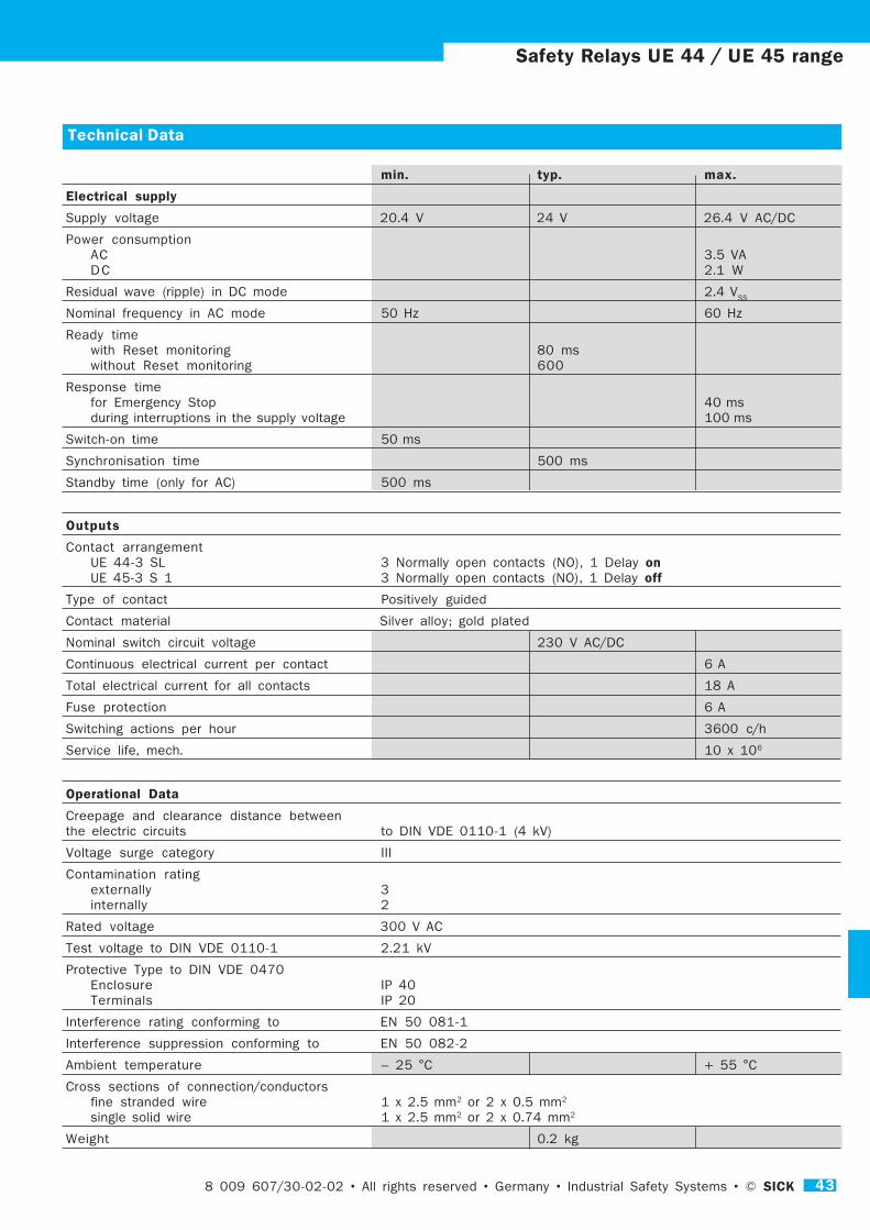
Safety Relays UE 44 / UE 45 range
Technical Data
min. typ. max.
Electrical supply
Supply voltage 20.4 V 24 V 26.4 V AC/DC
Power consumption
AC 3.5 VA
D C 2.1 W
Residual wave (ripple) in DC mode 2.4 VSS
Nominal frequency in AC mode 50 Hz 60 Hz
Ready time
with Reset monitoring 80 ms
without Reset monitoring 600
Response time
for Emergency Stop 40 ms
during interruptions in the supply voltage 100 ms
Switch-on time 50 ms
Synchronisation time 500 ms
Standby time (only for AC) 500 ms
Outputs
Contact arrangement
UE 44-3 SL 3 Normally open contacts (NO), 1 Delay onUE 45-3 S 1 3 Normally open contacts (NO), 1 Delay off
Type of contact Positively guided
Contact material Silver alloy; gold plated
Nominal switch circuit voltage 230 V AC/DC
Continuous electrical current per contact 6 A
Total electrical current for all contacts 18 A
Fuse protection 6 A
Switching actions per hour 3600 c/h
Service life, mech. 10 x 106
Operational Data
Creepage and clearance distance between
the electric circuits to DIN VDE 0110-1 (4 kV)
Voltage surge category III
Contamination rating
externally 3
internally 2
Rated voltage 300 V AC
Test voltage to DIN VDE 0110-1 2.21 kV
Protective Type to DIN VDE 0470
Enclosure IP 40
Terminals IP 20
Interference rating conforming to EN 50 081-1
Interference suppression conforming to EN 50 082-2
Ambient temperature – 25 °C + 55 °C
Cross sections of connection/conductors
fine stranded wire 1 x 2.5 mm2 or 2 x 0.5 mm2
single solid wire 1 x 2.5 mm2 or 2 x 0.74 mm2
Weight 0.2 kg

44 SICK © • Industrial Safety Systems • Germany • All rights reserved • 8 009 607/30-03-02
Safety Relays UE 44/45 range
Order List for UE 44 and UE 45
Type Outputs Connections Electrical supply Delay Part No.
Direct Removable terminals 24 V DC max. s
UE 44- 3 SL 2 D 3 3 6 024 907
UE 44- 3 SL 3 D 3 3 6 024 908
UE 44- 3 SL 2 D 3 3 0 6 024 909
UE 44- 3 SL 3 D 3 3 0 6 024 910
UE 45- 3 S 1 2 D 3 3 6 024 911
UE 45- 3 S 1 3 D 3 3 6 024 912
UE 45- 3 S 1 2 D 3 3 0 6 024 913
UE 45- 3 S 1 3 D 3 3 0 6 024 914

8 009 607/30-02-02 • All rights reserved • Germany • Industrial Safety Systems • © SICK 45
Safety Relays UE 48 range
UE 48-2 OSSafety RelayAutomatic or Manual Reset
Application
The UE 48-2 OS safety relay is used as
a processing module for:
� Safety Light Curtain
� Safety Laser Scanner
� Units with 2 Safety Switch outputs
(OSSD)
Features
� 2 Relays with positively guided
contacts (2 normally open, 1 normally
closed)
� 3 LEDs for supply voltage and relays
K 1 and K 2
� Contact expansion units UE 10-4 XT
and UE 11-4 DX can be connected
(for increasing the number of outputs)
� Enclosure A (see Page 3),
width: 22.5 mm
oder
8 009 607/30-03-02 • All rights reserved • Germany • Industrial Safety Systems • © SICK 45
1
2
or
EDM
EN 60 204-1 Stop Category 0
EN 954-1 Category 4
EN 61 496 Type 2, 3, 4

46 SICK © • Industrial Safety Systems • Germany • All rights reserved • 8 009 607/30-03-02
Safety Relays UE 48 range
Function
The inputs of the UE 48-2 OS are used for connecting
the two channels of the sensors of type 2, 3 and 4,
e. g. opto-electronic safety devices. These are verified
for uniformity and control the output relay.
After applying the supply voltage to the terminals A 1
and A 2, the green LED illuminates for indicating the
presence of the electrical supply. Release is effected
as selected – automatically or by Manual Reset. Upon
release of the safety device K 1 and K 2 switches off.
The normally open contacts open and the normally
closed circuit closes.
Manual ResetStart after activation and release of the reset switch
(S 33 - S 34)
Automatic ResetMake link wire connection between terminals S 35 -
S 12.
External Device Monitoring (EDM)The UE 48 takes over external device monitoring by
means of the Reset circuit.
The UE 48 OS 2 unit with screw terminals,
the UE 48 OS 3 unit with removable plug-in block
terminals.
-- +
--
+ + + +
Steckblockklemme
Geräteanschluss
Steckblockklemme
Geräteanschluss
Geräteanschluss
Steckblockklemme
Geräteanschluss
Steckblockklemme
3.1 3.2 3.3 3.4
13 23 24 31
1.1 1.2 1.3 1.4
A1 S33 S34S35
S21 S22 S31 A2
2.1 2.2 2.3 2.4
14 S11 S12 32
4.1 4.2 4.3 4.4
13 23 24 31
A1 S33 S34 S35
S21 S22 S31 A2
14 S11 S12 32
S34 S35 S12 S31 13 23 31
S21 S11 S33 S22 14 24 32
A1 A2
K1
K2Control- Logic
K1 K2
--
+ + + +
--
+
L+ (L1)
OSSD
M (N)
13 23 24 31 A1 S33 S34 S35
14 S11 S12 32
S21 S11 S33
A1 A2 S34 S35 S12 S31
K1
K2
S21 S22 S31 A2
Reset
Control- Logic
K1 K2
OSSD
Operation with a Safety Light Curtain
Circuit Wiring Diagram UE 48-2 OS
Plug-in screw terminal blocks
Screw terminals
Plug-in screw terminal blocks
Screw terminals
Screw terminals
Plug-in screw terminal blocks
Screw terminals
Plug-in screw terminal blocks

8 009 607/30-02-02 • All rights reserved • Germany • Industrial Safety Systems • © SICK 47
Safety Relays UE 48 range
Technical Data
min. typ. max.
Electrical supply
Supply voltage 20.4 V 24 V 26.4 V AC/DC
Power consumption
AC 3.5 VA
D C 2.1 W
Residual wave (ripple) in DC mode 2.4 VSS
Nominal frequency in AC mode 50 Hz 60 Hz
Ready time
with Reset monitoring 80 ms
Response time
for OSSDs 25 ms
during interruptions in the supply voltage 100 ms
Switch-on time 50 ms
Synchronisation time 500 ms
Standby time (only for AC) 500 ms
Outputs
Contact arrangement 2 Normally open contacts (NO)
1 Normally closed contact – for signal use (NC)
Type of contact Positively guided
Contact material Silver alloy; gold plated
Nominal switch circuit voltage 230 V AC/DC
Continuous electrical current per contact 6 A
Total electrical current for all contacts 18 A
Fuse protection 6 A
Switching actions per hour 3600 c/h
Service life, mech. 10 x 106
Operational Data
Creepage and clearance distance between
the electric circuits to DIN VDE 0110-1 (4 kV)
Voltage surge category III
Contamination rating
externally 3
internally 2
Rated voltage 300 V AC
Test voltage to DIN VDE 0110-1 2.21 kV
Protective Type to DIN VDE 0470
Enclosure IP 40
Terminals IP 20
Interference rating conforming to EN 50 081-1
Interference suppression conforming to EN 50 082-2
Ambient temperature – 25 °C + 55 °C
Cross sections of connection/conductors
fine stranded wire 1 x 2.5 mm2 or 2 x 0.5 mm2
single solid wire 1 x 2.5 mm2 or 2 x 0.74 mm2
Weight 0.2 kg
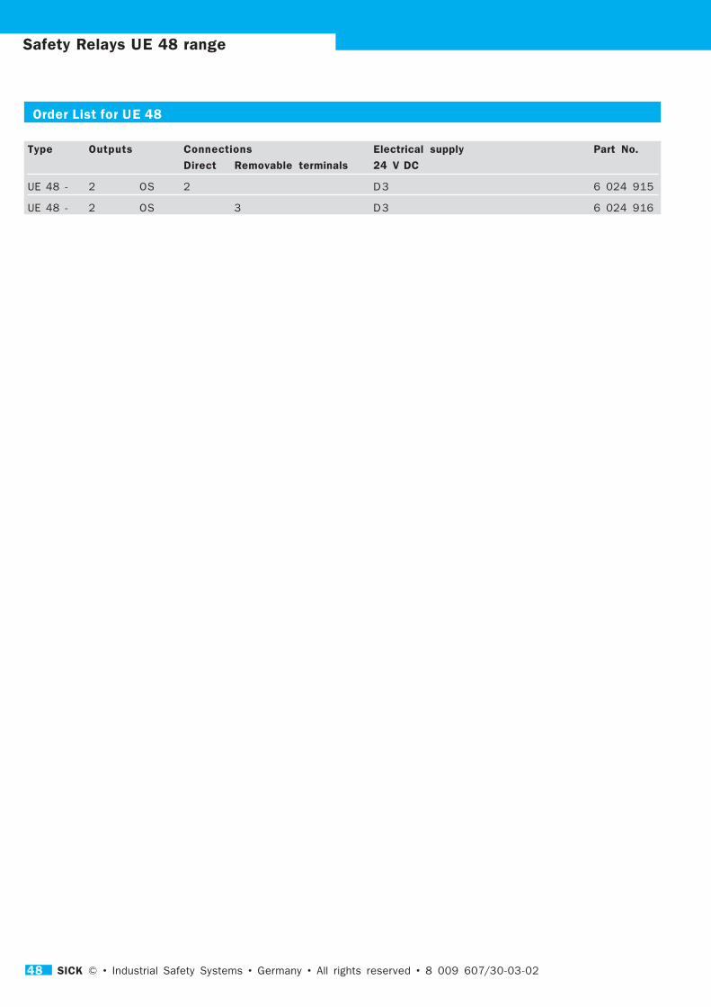
48 SICK © • Industrial Safety Systems • Germany • All rights reserved • 8 009 607/30-03-02
Safety Relays UE 48 range
Order List for UE 48
Type Outputs Connections Electrical supply Part No.
Direct Removable terminals 24 V DC
UE 48 - 2 OS 2 D 3 6 024 915
UE 48 - 2 OS 3 D 3 6 024 916

8 009 607/30-02-02 • All rights reserved • Germany • Industrial Safety Systems • © SICK 49

8 009 607/30-02-02 • All rights reserved • Germany • Industrial Safety Systems • © SICK 50
EN
60
20
4-1
EN
95
4-1
EN
6
1 4
96
EN
5
74
UE 10-3 OS 0 1 2, 3, 4
UE 10-4 XT 0 *)
UE 11-4 DX 1 *)
UE 34-2 TS 0 3 2
UE 42-2 HD 0 4 III C
UE 42-3 DR 0 4
UE 42-3 DD 0 4
UE 42-3 CP 0 4
UE 42-3 CZ 0 4
UE 43-2 MT 0 4
UE 43-2 MF 0 4
UE 43-3 MF 0 4
UE 43-6 MF 0 4
UE 44-3 SL 0 4
UE 45-3 S1 1 4
UE 48-2 OS 0 4 2, 3, 4 *) as basic unit
EN 60 204-1 Stop Category
EN 954-1 Safety Category
EN 61 496 Safety Type
UE
1
0-3
O
S
UE
1
0-4
X
T
UE
1
1-4
D
X
UE
3
4-2
T
S
UE
4
2-2
H
D
UE
4
2-3
D
R
UE
4
2-3
D
D
UE
4
2-3
C
P
UE
4
2-3
C
Z
UE
4
3-2
M
T
UE
4
3-2
M
F
UE
4
3-3
M
F
UE
4
3-6
M
F
UE
4
4-3
S
L
UE
4
5-3
S
1
UE
4
8-2
O
S
Applications
Basic unit � � � � � � � � � � � � �
Contact expansion unit � �
Emergency Stop application � � � � � � � �
Safety Switch (on movable guard) � � � � � � � � � �
Two hand operation �
Pressure mat operation �
Opto-electronic safety device � �
Simultaneous monitoring � � �
Synchronisation time monitoring � � � � � � � �
Testable sensors �
Automatic Reset � � � � � � � � � � � �
Manual Reset � � � � � � � � � � �
Safety Navigator
Standards

8 009 607/30-02-02 • All rights reserved • Germany • Industrial Safety Systems • © SICK 51
Safety Navigator: please unfold

SICK AG · Industrial Safety Systems · P.O. Box 310 · 79177 Waldkirch · Deutschland
Phone +49 76 81 2 02 0 · Fax +49 76 81 2 02 38 15 · www.sick.de8 0
09
607/3
0-0
3-0
2 · K
W/S
M · P
rinte
d in G
erm
any
(04
.02
) ·S
ubje
ct
to c
hange w
ithout
prior
notice
GB
9.0
2 T
B Your contacts:
A u s t r a l i aPhone +61 3 94 97 41 00
008 33 48 02 – toll freeFax +61 3 94 97 11 87
A u s t r i aPhone +43 2 23 66 22 88-0Fax +43 2 23 66 22 88-5
B e l g i u m / L u x e m b o u r gPhone +32 24 66 55 66Fax +32 24 63 31 04
B r a z i lPhone +55 11 55 61 26 83Fax +55 11 55 35 41 53
C h i n aPhone +8 52 27 63 69 66Fax +8 52 27 63 63 11
C z e c h R e p u b l i kPhone +42 02 578 10 561Fax +42 02 578 10 559
D e n m a r kPhone +45 45 82 64 00Fax +45 45 82 64 01
F i n l a n dPhone +3 58 9-728 85 00Fax +3 58 9-72 88 50 55
F r a n c ePhone +33 1 64 62 35 00Fax +33 1 64 62 35 77
G e r m a n yPhone +49 2 11 53 01 0Fax +49 2 11 53 01 100
G r e a t B r i t a i nPhone +44 17 27-83 11 21Fax +44 17 27-85 67 67
I t a l yPhone +39 02 92 14 20 62Fax +39 02 92 14 20 67
J a p a nPhone +813 33 58 13 41Fax +813 33 58 05 86
K o r e aPhone +82 2 786 63 21-4Fax +82 2 786 63 25
N e t h e r l a n d sPhone +31 30 229 25 44Fax +31 30 229 39 94
N o r w a yPhone +47 67 56 75 00Fax +47 67 56 66 10
P o l a n dPhone +48 22 8 37 40 50Fax +48 22 8 37 43 88
S i n g a p o r ePhone +65 67 44 37 32Fax +65 68 41 77 47
S p a i nPhone +34 93 4 80 31 00Fax +34 93 4 73 44 69
S w e d e nPhone +46 8 6 80 64 50Fax +46 8 7 10 18 75
S w i t z e r l a n dPhone +41 4 16 19 29 39Fax +41 4 16 19 29 21
T a i w a nPhone +88 62 23 65 62 92Fax +88 62 23 68 73 97
U S APhone +1(952) 9 41-67 80Fax +1(952) 9 41-92 87
Representatives and agencies
in all major industrial nations.