Embed Size (px)
Citation preview

California State Lands Commission
Safety and Oil Spill Prevention Audit
Ellwood Onshore Facility
Venoco, Inc.
November 2011

TABLE OF CONTENTS
EXECUTIVE SUMMARY
1.0 INTRODUCTION
1.1 Safety Audit Background 1.2 Facility History 1.3 Facility Descriptions
2.0 FACILITY CONDITION AUDIT
2.1 Goals and Methodology
2.2 General Facility Conditions
2.2.1 Housekeeping 2.2.2 Stairs, Walkways, Gratings and Ladders 2.2.3 Escape / Emergency Egress / Exits 2.2.4 Labeling, Color Coding and Signs 2.2.5 Security 2.2.6 Hazardous Material Handling and Storage
2.3 Field Verification of Plans
2.3.1 Process Flow Diagrams (PFD) 2.3.2 Piping & Instrumentation Diagrams (P&ID) 2.3.3 Fire Protection Drawings
2.4 Condition and Integrity of Major Systems
2.4.1 Piping 2.4.2 Tanks 2.4.3 Pressure Vessels 2.4.4 Relief System 2.4.5 Fire Detection Systems 2.4.6 Fire Fighting Equipment 2.4.7 Combustible Gas and H2S Detection 2.4.8 Emergency Shutdown System (ESD) 2.4.9 Safety and Personal Protective Equipment (PPE) 2.4.10 Lighting 2.4.11 Instrumentation, Alarm and Paging 2.4.12 Auxiliary / Emergency Generator 2.4.13 Spill Containment 2.4.14 Spill Response
2.5 Preventive Maintenance and Mechanical Reliability 3.0 ADMINISTRATIVE AUDIT
3.1 Goals and Methodology

3.2 Operations Manual 3.3 Spill Response Plan 3.4 Applicable Documents & Records 3.5 Training, Drills & Applications
4.0 HUMAN FACTORS AUDIT
4.1 Goals of the Human Factors Audit 4.2 Human Factors Audit Methodology
5.0 APPENDICES
A.1 Team Members A.2 Acronyms A.3 References

EXECUTIVE SUMMARY

Executive Summary
Ellwood Facility Safety Audit 1
Executive Summary
Safety Audit of Ellwood Onshore Facility A safety audit of the Ellwood Facility was conducted in February 2011 with the field work completed in July 2011. The objective of the Safety Audit is to ensure that each oil and gas production facilities on State leases are operated in a safe and environmentally sound manner. The audit followed the established procedures that have been used by CSLC for many years. Background Venoco Inc. (Venoco), with corporate headquarters in Denver, CO and regional offices in Carpentaria, CA and Houston, TX is an independent oil and gas company engaged in developing and producing domestic oil and gas properties primarily in California and Texas. Venoco’s California core operations are located in and around the Santa Barbara Channel and in the Sacramento Basin. The Ellwood Offshore Facility (EOF), located in Goleta, CA processes oil and gas from Venoco’s Platform Holly and from "seep tents" constructed over two of the natural seeps on the ocean floor to the Ellwood Facility. Platform Holly is located approximately 2 miles offshore in the Santa Barbara Channel and produces from State Oil and Gas Leases PRC 3120 and PRC 3242.
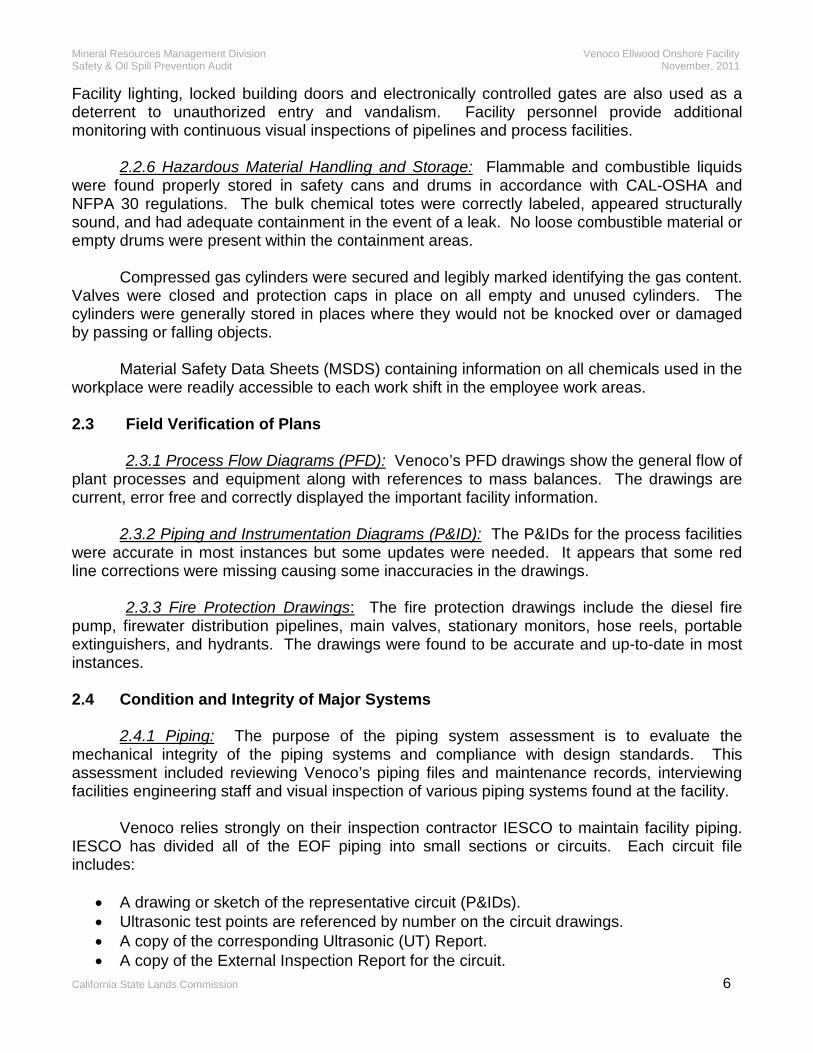
Safety Audit Results The safety audit identified 66 minor priority three action items that have a low risk potential for injury, oil spill, adverse environmental impacts, or property damage. The priority three items normally require correction within 180 days and represent past due vessel inspections and administrative errors. There was one priority two action item that was identified involving an incomplete relief valve maintenance procedure. When this condition was brought to Venoco’s attention, they reacted in a responsible manner by swiftly correcting the deficiency. The following chart displays the number of action items from Venoco’s 2005 safety audit verses the number of action items (67) identified on their 2011 audit. There has been a significant decrease (64%) in the number of action items from the previous audit. This decrease demonstrates Venoco’s continued commitment to peak safety performance and safety program strategies.

Executive Summary
Ellwood Facility Safety Audit 2
Conclusion The Ellwood Facility appeared clean and well organized. The facility design and strategy is based on sound engineering principles and accepted industry practices. A comprehensive mechanical integrity program is established and equipment appears to be operated and maintained correctly. A high level of plant ownership in Venoco’s employees’ enhances reliability performance and team work. Personnel were knowledgeable in the process, understood cause-effect relationships and demonstrated responsibility for the environment.
0
100
200
20052011
Action Item Summary - Ellwood Facility
Action Item Summary -Ellwood Facility Items

Introduction

Mineral Resources Management Division Venoco Ellwood Onshore Facility Safety & Oil Spill Prevention Audit November, 2011
California State Lands Commission 1
1.0 INTRODUCTION
1.1 Safety Audit Background
The California State Lands Commission (CSLC) Mineral Resources Management Division (MRMD) staff conducts detailed safety audits of operators and/or contractors. The objective of these safety audits is to ensure that all oil and gas production facilities on State leases or granted lands are operated in a safe and environmentally sound manner and comply with Federal, State, and local codes/permits, as well as industry standards and practices. The MRMD staff is tasked with providing for the prevention and elimination of any contamination or pollution of the ocean and tidelands, for the prevention of waste, for the conservation of natural resources, and for the protection of human health, safety and property by sections 6103, 6108, 6216, 6301, and 6873(d) of the Public Resources Code (PRC). These PRC sections provide authority for MRMD regulations as well as the existing inspection program and the safety audit program that augments it.
The Safety Audit Program was developed in response to PRC 8757(a), which originated from the Lempert, Keene, and Seastrand Oil Spill Prevention Act. In this Act, existing oil spill prevention programs were considered insufficient to reduce the risk of significant discharges of petroleum into marine waters. Marine facilities were specifically required to employ best achievable technology or protection and the CSLC was required to regularly inspect all marine facilities and monitor their operations and their effects on public health and safety, and the environment. The Safety Audit Program was established, as a result, to augment the existing inspection program, further preventing oil spills and other accidents. The Safety Audit Program augments prevention efforts by way of a thorough review of design, maintenance, human factors, and other evolving areas.
The MRMD uses four teams, each with specific focus, to conduct the safety audit. The four teams systematically evaluate the facilities, operations, personnel, and management from many different perspectives. The four teams and their areas of emphasis include:
1) Equipment Functionality and Integrity (EFI) 2) Technical (TEC) 3) Administrative (ADM) 4) Human Factors (HF) Appropriate company contacts and resources are identified for each team. Progress
and inspection deficiency reports are communicated periodically throughout the audit evaluations. Each team records findings on an “action item matrix” for its area with recommended corrective actions and a priority ranking for the specified corrective action. Because of the overlap of functions, more than one team may identify some items, but, the duplication of findings across multiple teams has been reduced as much as possible.
The audit report highlights the findings of each team and the most significant action
items and includes references to the complete matrix of action items. Draft copies of the audit report and the matrix of action items are provided to the company periodically throughout the audit. The final audit report is provided to company management and discusses the findings and the corrective actions proposed. The MRMD continues to assist the operator in resolving

Mineral Resources Management Division Venoco Ellwood Onshore Facility Safety & Oil Spill Prevention Audit November, 2011
California State Lands Commission 2
the action items and tracks progress of the proposed corrective actions. Adjustments to the inspection program can be made based on the Safety Audit.
This program could not be successfully undertaken without the cooperation and support of the operating company. It is designed to benefit both the company and the State by reducing the risk of personnel or environmental accidents, damage, and in particular, oil spills. Previous experience shows that the safety assessments help increase operating effectiveness and efficiency and lower cost. History has shown that improving safety and reducing accidents makes good business sense. 1.2 Ellwood Onshore Facility History
Venoco, LLC is an independent energy company primarily engaged in the acquisition, exploitation and development of oil and natural gas. Venoco has corporate offices in Denver, Colorado with regional offices in Carpinteria and Bakersfield, California. Venoco operates three offshore platforms in the Santa Barbara Channel as well as two onshore properties in Southern California. Venoco also operates or has a financial interest in over 100 wells in the Sacramento Basin of California.
The Ellwood Onshore Facility (EOF), operated by Venoco, is located on an approximate 4-1/2 acre site west of the city of Goleta roughly 1200 feet inland from the Pacific Ocean and approximately 20 feet above sea level. The facility is located south of the Union Pacific Railroad tracks along Hollister Avenue and situated between Sandpiper Golf Course to the east and Bacara Spa & Resort to the west. EOF was built between 1965 and 1967 by ARCO and Mobil and was expanded in 1978 to process sour gas. Mobil took control in 1993, and Venoco subsequently purchased the facility and has operated it since 1997.
EOF is designed to receive crude oil and natural gas both containing hydrogen sulfide
(H2S) from Platform Holly via two separate 6” sub-sea pipelines. Natural gas is also received via a 6” sub-sea pipeline from the Seep Recovery Tents in the Santa Barbara Channel. Emulsion from Platform Holly is separated into gas, oil, and produced water, with the gas flowing to the LO-CAT for hydrogen sulfide removal, the oil being treated for H2S removal, and the produced water injected into the salt water disposal well. The separated oil is then shipped to the Ellwood Marine Terminal for loading to barges.
The facility is permitted to process 13,000 BPD dry oil and 13,000 MSCFD gas,
although currently the production is 2,500 BPD oil and 1,600 MSCFD gas from Platform Holly and another 250 MSCFD gas from the Seep Tents. 1.3 Ellwood Onshore Facility Description Crude oil and natural gas produced from wells on Platform Holly is routed through separate subsea pipelines to EOF. Before leaving Platform Holly, the gas is compressed, scrubbed and partially dehydrated and a portion is used for the gas lift in the production wells. The remainder is sent to EOF to be treated and sold as sales gas.
The crude oil arrives at EOF in an emulsion state. Heat required to break out the entrained water is achieved by passing the emulsion through double heat exchanger banks

Mineral Resources Management Division Venoco Ellwood Onshore Facility Safety & Oil Spill Prevention Audit November, 2011
California State Lands Commission 3
where it is preheated to 150° F before flowing on to heater treaters. Supplemental chemical treatment at the heater treaters allows the entrained water to settle out. Dry crude flows through parallel stripper columns where sweet gas is used to strip out the H2S before the crude is allowed to run down to an oil surge tank for settling. To reclaim heat, dry clean crude from the surge tank is pumped back through a heat exchanger before arriving at the shipping tank for interim storage. Crude oil from the shipping tank is metered through a Lease Automated Custody Transfer (LACT) unit before shipment via pipeline to the Ellwood Marine Terminal. Crude oil stored at the terminal is loaded onto an ocean going barge for shipment to refining facilities. Off gas from the heater treaters is merged with the Holly pipeline gas and chilled to recover natural gas liquids (NGL). NGL’s are stored in a 25,000 gallon bullet prior to being trucked. The remaining gas stream is routed to the LO-CAT unit for sweetening. There H2S is removed from the gas stream by direct contact with an aqueous chelated iron solution. The rich solution is regenerated with air spargers, converting hydrogen sulfide to elemental sulfur, which is stored and loaded into trucks. The regenerated solution is recycled for continued desulphurization.
Seep gas, which is recovered from two large tents placed on the ocean bottom, is received at EOF via a 6” sub-sea pipeline. Seep gas is normally processed with the gas stream from the LO-CAT unit and is compressed to 480 psi, chilled to -25° F, and dehydrated using triethylene glycol. Refrigeration for the gas cooling process is provided by a propane refrigeration unit. After water and liquefied petroleum gas (LPG) are removed, the pressure is further compressed to 980 psi. before passing through the Grace Membrane unit for residual carbon dioxide (CO2) removal. The gas stream is delivered as sales gas to the 8” SoCal Gas pipeline at 975 psi. LPG is recovered in the dehydration unit by first being separated from the glycol, then stabilized to remove light ends, and piped to a 25,000 gallon storage bullet. LPG is then loaded into trucks for transport.
The vapor recovery system consists of four compressors, VRU-1, VRU-2, VRU-3, and VRU-4, which are run two at a time in series. More specifically, the first stage of the two series collects vapors from all zero to low pressure devices, such as the oil surge tanks, the hydrocarbon sump and the oil sump. The outlet of the back pressure control valves that maintain pressure on the LPG and NGL tanks also connects to the first stage VRU. The collected vapors are than scrubbed in Suction Scrubber V-235 and compressed by either VRU-1 or VRU-3 to 25 psi. and directed to the second stage of the vapor recovery. In addition to the first stage discharge, the second stage of vapor recovery collects vapors from the crude oil heater treaters and the H2S strippers. Here the vapors are scrubbed in suction scrubber V-236 and compressed by either VRU-2 or VRU-4 to 50 psi, chilled to remove NGL, and finally added to the main sour gas flow prior to the inlet to Chiller E-222.
Produced water removed from the oil emulsion in the heater treaters flows to a settling tank for removal of any residual oil. From there water is pumped down an onsite disposal well.
The EOF relief system consists of three Hirt Burners to incinerate gas. Relief gas from
various systems throughout EOF vent to the relief system during normal operations. In the

Mineral Resources Management Division Venoco Ellwood Onshore Facility Safety & Oil Spill Prevention Audit November, 2011
California State Lands Commission 4
event that a process upset triggers a high pressure deviation, the gas will be sent to the relief system through pressure safety valves. Once in the relief system, gas is combusted in either H-205 or H-206. If the pressure in the relief system continues to rise, relief gas cascades to open H-207.

Facility Condition
Audit

Mineral Resources Management Division Venoco Ellwood Onshore Facility Safety & Oil Spill Prevention Audit November, 2011
California State Lands Commission 5
2.0 FACILITY CONDITION AUDIT
2.1 Goals and Methodology The primary goal of the Audit Team was to evaluate the design, condition, and maintenance of the Ellwood Onshore Facility (EOF) and associated process equipment. A series of system, equipment inspections, field verifications of key drawings/plans, and technical design review of systems were employed to accomplish this goal. The layout of the report reflects this methodology. 2.2 General Facility Conditions 2.2.1 Housekeeping: EOF was exceptionally clean and orderly. There was an adequate supply of clearly marked refuse containers with no excess of oilfield wastes and refuse. The restroom was in satisfactory condition with no obvious health or sanitation concerns. Organizational policies throughout Venoco encourage workers to maintain a clean, safe, and productive workplace. 2.2.2 Stairs, Walkways, Gratings and Ladders: Stairs, walkways, and gratings at EOF appear to be of a safe design and construction. Safeguards were provided at transitions between levels and for access to equipment. The aisles, passageways, stairs, and gratings appeared to be in good repair, and were clear with no obstructions that could create a hazard. The portable ladders appeared in good usable condition free from oil and grease. Fixed metal ladders and appurtenances were painted to resist corrosion and rusting. Safe work practices cover the use and care of ladder equipment on the facility. 2.2.3 Escape / Emergency Egress / Exits: Venoco’s onshore process facility Escape / Emergency Egress / Exits were clearly posted, accessible and part of their Emergency Action Plan. The workplace has two exit routes to permit prompt evacuation of employees and other personnel during an emergency. These exit routes are located on opposite ends of the facility and lead directly outside to a street or public way, with the access to the outside large enough to accommodate the facility personnel. 2.2.4 Labeling, Color Coding and Signs: The design, application, and use of signs and symbols within the facilities define the specific hazards to workers and/or public. All employees are instructed on what the signs indicate and what, if any, special precautions are necessary to perform their task safely. Physical hazards such as tripping hazards are identified by yellow and fire protection equipment by red. By providing identification with (labeling, color-coding, and signs) Venoco has helped to address these risks. Fire diamonds were visible on all tanks, vessels, buildings, and chemical storage totes. The fire diamonds were posted so that when facility doors are open or shut, the fire diamonds remain easily and readily visible. The posting of fire diamonds is an indication of good facility emergency planning and conformance with The Uniform Fire Code. 2.2.5 Security: Physical and operational security measures are in place to prevent unauthorized entry into the onshore facilities. The onshore process facilities are manned twenty-four hours a day, seven days a week with at least two operators present at all times.
Mineral Resources Management Division Venoco Ellwood Onshore Facility Safety & Oil Spill Prevention Audit November, 2011
California State Lands Commission 6
Facility lighting, locked building doors and electronically controlled gates are also used as a deterrent to unauthorized entry and vandalism. Facility personnel provide additional monitoring with continuous visual inspections of pipelines and process facilities. 2.2.6 Hazardous Material Handling and Storage: Flammable and combustible liquids were found properly stored in safety cans and drums in accordance with CAL-OSHA and NFPA 30 regulations. The bulk chemical totes were correctly labeled, appeared structurally sound, and had adequate containment in the event of a leak. No loose combustible material or empty drums were present within the containment areas. Compressed gas cylinders were secured and legibly marked identifying the gas content. Valves were closed and protection caps in place on all empty and unused cylinders. The cylinders were generally stored in places where they would not be knocked over or damaged by passing or falling objects. Material Safety Data Sheets (MSDS) containing information on all chemicals used in the workplace were readily accessible to each work shift in the employee work areas. 2.3 Field Verification of Plans 2.3.1 Process Flow Diagrams (PFD): Venoco’s PFD drawings show the general flow of plant processes and equipment along with references to mass balances. The drawings are current, error free and correctly displayed the important facility information. 2.3.2 Piping and Instrumentation Diagrams (P&ID): The P&IDs for the process facilities were accurate in most instances but some updates were needed. It appears that some red line corrections were missing causing some inaccuracies in the drawings. 2.3.3 Fire Protection Drawings: The fire protection drawings include the diesel fire pump, firewater distribution pipelines, main valves, stationary monitors, hose reels, portable extinguishers, and hydrants. The drawings were found to be accurate and up-to-date in most instances. 2.4 Condition and Integrity of Major Systems 2.4.1 Piping: The purpose of the piping system assessment is to evaluate the mechanical integrity of the piping systems and compliance with design standards. This assessment included reviewing Venoco’s piping files and maintenance records, interviewing facilities engineering staff and visual inspection of various piping systems found at the facility. Venoco relies strongly on their inspection contractor IESCO to maintain facility piping. IESCO has divided all of the EOF piping into small sections or circuits. Each circuit file includes:
• A drawing or sketch of the representative circuit (P&IDs). • Ultrasonic test points are referenced by number on the circuit drawings. • A copy of the corresponding Ultrasonic (UT) Report. • A copy of the External Inspection Report for the circuit.
Mineral Resources Management Division Venoco Ellwood Onshore Facility Safety & Oil Spill Prevention Audit November, 2011
California State Lands Commission 7
Baker Petrolite provides the facility with a chemical treatment program that satisfies the operational needs of Venoco. This corrosion inhibitor service protects facility equipment and pipelines by reducing risk. Additionally, the program incorporates corrosion coupons at critical points in the piping for monitoring chemical treatment effectiveness.
Maintenance records reflect a proactive approach to evaluating the risk significance of degraded piping. Completed work orders with identifiable H2S corrosion degradation showed that proper repair/replacement of the piping is being done. Visual inspection of facility piping included checks for leaks, missing or damaged pipe supports, excess vibration, and signs of external corrosion. Piping components such as valves, flanges, bolts, welds, etc. appeared compatible with the environment and operating temperature. The visual inspection found the condition and maintenance of piping throughout the facility to appear satisfactory. 2.4.2 Tanks: Facility tanks are subject to the company’s periodic inspection program and API RP 653 recommendations throughout their service life. Available records document design information, corrosion rates, maintenance activities, and events that have affected tank integrity. Inspection methods used include ultrasonic, external and internal inspection methods to search for flaws and service induced damage as recommended in API 653. Tank coatings, piping, valves, walls, anchor bolts, and labeling appeared to be in good condition with no evidence of damage or leaks. There also were no external signs of shell or roof buckling, cracking of welds, or indications of tank settlement problems. Three tanks required follow up inspections that were due in the first quarter of 2011 but had not yet been performed by the second quarter of 2011. (EFI 2.4.2.01 thru 03) To help prevent liquid overflow and leaks, safety instrumentation for the process tanks consists of high and low level alarms and switches. These high and low level sensors are displayed on facility computers and local alarms alert operators to changing tank conditions. 2.4.3 Pressure Vessels: The pressure vessel assessment included an external inspection and a review of Venoco’s inspection history as well as any alterations or repairs made. Records typically contained the results of external, internal, or both inspections and the documentation of non-destructive examination techniques. A review of these inspection records, construction and maintenance logs, found they were well organized with minimal exceptions. Venoco compared the safety audit review of vessel records with their inspection contractor (IESCO) information to help eliminate misfiled or missing reports and added deficiencies to their 2011 inspection status. Seventeen priority three action items were written as a result of this review. One action item resulted because IESCO had not followed up in a timely manner with an internal inspection to ascertain if repairs might be required on instrument air receiver V-237 after an ultrasonic inspection report indicated one point below T-min. (EFI - 2.4.3.04) The balance of the items is relatively minor and appears to be caused by scheduling difficulties with the inspection company. Most of the items resulted because certain required follow up inspections that were due in the fourth quarter of 2010 or first quarter of

Mineral Resources Management Division Venoco Ellwood Onshore Facility Safety & Oil Spill Prevention Audit November, 2011
California State Lands Commission 8
2011 had not yet been performed by the second quarter of 2011. (EFI 2.4.3.01 thru 2.4.3.03 & 2.4.3.05 thru 2.4.3.13) An external inspection was done to assess the overall condition of the facility pressure vessels for specific problems such as coating failure, leakage, distortion or cracks at welds and vessel connection defects. The visual inspection of the pressure vessels found no major problems or defects with only minor concerns. In addition, all vessels are equipped with ASME required safety devices. Minor concerns included two compressor scrubbers that utilized reinforcement plates in the manufacturing process to attach man ways and inlet piping. The weep holes in the reinforcement plates were found to be plugged with ¼” plugs. Normally, weep holes in reinforcement plates should remain open to provide visual evidence of leakage as well as to prevent any pressure build-up behind the reinforcement plates. (EFI 2.4.3.14 & 15) The fire proofing on a NGL storage vessel and a LPG storage vessel require minor repairs due to flaking and hairline cracks respectively. Repairs are required to prevent moisture from being trapped under the fireproofing and potentially allowing localized corrosion. (EFI 2.4.3.16 & 17) Venoco’s management viewed issues that arose during our vessel review as an opportunity for improvement. Through their application of Good Management Practices and the use of sound technical expertise, Venoco has successfully implemented a comprehensive mechanical integrity program. 2.4.4 Relief System: The relief / flare system at EOF was evaluated for condition, maintenance, and functionality. Vented hydrocarbon and vapor flow to a flare scrubber (V-221) for removal of any entrained liquid before traveling into a header system connected to two thermal oxidizers (H-205 & H-206) and a ground flare (H-207). Should overpressure occur at the flare scrubber, two pressure-relieving devices set five pounds apart on the flare scrubber will relieve into the section of the header system connected to the thermal oxidizers (H-206 and H-207) and ground flare (H-207). No deficiencies were noted. The maintenance and servicing intervals for all pressure safety valves (PSVs) on the pressure vessels were examined and found to comply with applicable regulations and recommended standards, as well as, record keeping within a preventive maintenance system, MRMD 2132 (g)(3)(D) and 2175 (b)(5)(B), API RP 520, 521 and Cal OSHA 6551. Pressure safety valves (PSV) are tested and serviced yearly by Ventura Valve Service. Service records were in order with no action items identified. 2.4.5 Fire Detection Systems: The EOF fire detection system utilizes 43 ultraviolet/infrared fire eye flame-sensing detectors that will activate the fire suppression system and result in a shutdown of the facility. These detectors have been positioned to provide the required coverage to protect the most critical areas of the facility. Fire alarms have a distinct tone and are audible throughout the facility. Fire alarms are also wired to the Goleta Fire Department. Smoke detectors are also utilized. Fire alarms are tested monthly. No deficiencies were noted.
2.4.6 Fire Fighting Equipment: The EOF fire suppression system consists of identical
primary and secondary firewater pumps made by Aurora and rated at 1000 gpm @ 1750 RPM.

Mineral Resources Management Division Venoco Ellwood Onshore Facility Safety & Oil Spill Prevention Audit November, 2011
California State Lands Commission 9
The primary is powered by a 200 Hp. Electric motor and the secondary is powered by a 200 Hp. Detroit diesel. City water for firefighting is gravity fed by two 3000 barrel bolted tanks set on elevated grade. The Fire Department can also pump additional firewater via a 6” 4-way fire department connection (FDC) located on Hollister Avenue across from the Sandpiper Golf Course. A pressure maintenance pump holds constant pressure on the firewater system. In the event of fire, the primary firewater pump will be activated by a fire detection device in the emergency support system. Manual activation of the firewater pump is also possible. If the pressure drops below 100 psi after activation of the primary pump, the secondary firewater pump will automatically start.
The firewater system consists of an 8” pressurized loop system supplying firewater to
fire monitors, hose reels, hydrants, the deluge system and the foam system. Laterals from the main loop connect to a manually operated deluge system designed to protect two 40,000-gallon LPG/NGL bullet tanks. Fire protective coatings on the bullet tanks will help protect against flame impingement. A 1200-gallon foam tank supplies foam via a 6” line to nine fixed foam monitors and three oil storage tanks. Internal piping within the oil storage tanks allows a fire to be smothered with foam. Additional fire suppression is available through the 150-pound wheeled extinguishers as well as the 30-pound portable extinguishers strategically placed throughout the facility.
MRMD recognizes that the City of Goleta has primary authority regarding firefighting
requirements at the facility. The fire suppression system is understood to currently meet Goleta’s requirements along with the MRMD requirement that a firefighting system be installed and maintained in accordance with applicable NFPA standards. Venoco uses Joy Equipment Protection, Inc. of Carpentaria for annual flow testing of monitors, hoses and hydrants; foam tank service and testing; hose inspection; and annual fire extinguisher service. The firewater pumps are tested weekly and the deluge is tested monthly per MRMD regulations.
Venoco operating personnel who are trained annually in fire extinguisher use have the
option of extinguishing a small fire but would rely on Santa Barbara County Fire Station 11 located approximately 2 ½ miles from the facility for a major response. 2.4.7 Combustible Gas and H2S Detection Systems: The EOF has 21 fixed lower explosive level (LEL) detectors that protect against combustible gas and 25-fixed hydrogen sulfide (H2S) detectors that protect against a gas that is potentially fatal and immediately dangerous to life and health. The placement of both types of sensors is designed per requirements to provide sufficient warning for operating personnel. LEL and H2S detection alarms on the main control board annunciator are segregated by plant zone. Both types are tested monthly and records are maintained. No deficiencies were noted. Due to the close proximity to the Sandpiper Golf Course, the Bacara Resort & Spa and more recently to a gated residential community, the Ellwood Onshore Facility utilizes a number of additional safe guards to protect the general public and emergency responders. In conjunction with the Santa Barbara County Office of Emergency Services and Santa Barbara County Fire Department, Venoco has established an Emergency Warning and Notification System (EWNS) for the Ellwood Onshore Facility that utilizes sirens to alert the public to any emergency condition that could affect their safety. In addition, emergency call boxes with Fire Department locks are located along Hollister Avenue on both sides of the facility.

Mineral Resources Management Division Venoco Ellwood Onshore Facility Safety & Oil Spill Prevention Audit November, 2011
California State Lands Commission 10
The EWNS coverage area is along Hollister Avenue on the south side of the 101 Freeway and along Calle Real on the north side of the freeway respectively. Signs with general precautionary information for the public are posted in the coverage area. An annual siren test is held the last week of June to test the effectiveness of the system. In the event of an H2S release, the front entry gates to the facility remain closed and are rendered inoperable to prevent entry into the facility. Because the wind direction in the area is typically northwesterly, the Fire Department has developed the ability to approach the facility from the west by utilizing a portable bridge to cross the railroad tracks.
Based upon gas dispersion modeling for the facility, one of two NGL storage vessels and one of two LPG storage vessels are out of service to effectively limit the amount of product that could be stored at the facility and thereby limiting the severity of any potential spills or releases. 2.4.8 Emergency Shutdown System (ESD): The Ellwood Onshore Facility is equipped with both manual and automatic emergency shutdown (ESD) protection. The manual ESD stations include:
• ESD–1 at the main entrance gate • ESD–2 at the main exit gate • ESD–3 at the gate leading to the heliport • ESD–4 in the Operations Control Room
In addition to the manual ESD stations, activation of other critical alarms will also
activate an emergency shutdown. Specifically, activation of H2S, LEL, fire detection and certain high-level shutdown alarms cause a complete shutdown of the facility. The ESD system is tested semi-annually and the testing is documented. No deficiencies were noted. 2.4.9 Safety and Personal Protective Equipment (PPE): Venoco has a written workplace safety program for identifying, evaluating, analyzing, and controlling workplace safety and health hazards. This program has systematic policies, procedures, and practices that are fundamental to creating and maintaining a safe and healthy working environment. Venoco also considers the prevention of occupational injury and illness to be of such importance that it is given precedence over productivity.
Personal protective equipment (PPE) is used to reduce employee exposure to hazards when engineering and administrative controls are not feasible or effective in reducing these exposures to acceptable levels. An assessment of their policy found that the company regularly assesses the workplace to determine if hazards are present that require the use of PPE. Hazards are then communicated to the employees, appropriate PPE is selected, and workers are trained in its use. Employees were observed using appropriate PPE as required by company policy or where known hazards exist.
2.4.10 Lighting: Fixtures installed throughout the facility appear to provide adequate lighting levels for performing tasks. Pole-mounted fixtures with high-pressure sodium vapor lamps provide area lighting. This method of artificial light appears to conform to work area lighting and hazardous conditions requirements.
Mineral Resources Management Division Venoco Ellwood Onshore Facility Safety & Oil Spill Prevention Audit November, 2011
California State Lands Commission 11
2.4.11 Instrumentation, Alarm and Paging: Major equipment, process controls and alarms are graphically displayed using Wonderware software. Process control and monitoring computers and PLC’s are linked over a Modbus + network and function through the Wonderware software package. EOF process alarms are displayed on the control room process computers while fire and gas alarms are segregated by zone on the panel. Event logging (errors, alarms and system messages) is captured by the Wonderware system and can be printed on demand. The EOF also monitors process status at Platform Holly via microwave link but has no control capability over platform operations or systems. The facility instrumentation is tested, maintained, and calibrated on a regular schedule. Records are readily available and the device history can be tracked through the maintenance database program. All “direct read” instrumentation appeared to be properly maintained and in good operating condition. There were no conditions or maintenance issues identified with these systems. 2.4.12 Auxiliary / Emergency Generator: Standby power for the EOF is provided by a 400-kW, 480-volt, 3-phase auxiliary generator manufactured by Lima Electric and powered by a Detroit diesel. The standby generator starts automatically during a total power failure or power dip to supply power through an automatic transfer switch (ATS) to the gas and fire detection systems, alarm sensors, PLC’s, instrument air compressors, facility lighting, hydrocarbon sump, and the Vapor Recovery Unit (VRU) compressor 1st stage as well as auxiliary equipment for the VRU. The generator has an integral fuel tank (78-gallon) that provides approximately 4 hours of electrical power.
EOF also has an uninterruptible power supply (UPS) for the PLC system. During an initial power failure or power dip, the PLC’s automatically switch to the UPS system before transferring to auxiliary generator power after the generator starts. In the event that the generator does not start, the UPS system is capable of providing power for all PLC’s, fire detectors, gas detectors, as well as other emergency shut-down (ESD) related equipment for a minimum of 2 hours to allow the safe shutdown of the entire facility.
Venoco has established a schedule of maintenance and service based on recognized
and generally accepted good engineering practices. The frequency of inspection and tests of the emergency generator are consistent with applicable manufactures’ recommendations, NFPA standards and MRMD regulations. 2.4.13 Spill Containment: In general, the spill containment appeared to be adequate throughout the facility. Raised asphalt berms, block walls and the below ground area encompassing the LO-CAT Unit as well as the below ground area east of the oil storage tanks referred to as the Fluor cellar provides the capacity needed for containment. All hydrocarbons drain to the Hydrocarbon Sump located in the Fluor cellar where they are pumped back into the system via the Heater Treater. All storm water drains flow to the Storm Water Sump also located in the Fluor cellar. All storm water is held and allowed to backup into the Fluor cellar if necessary until test results by an independent third party laboratory confirm that the storm water is in compliance with the parameters of the Regional Water Quality Control Board. All laboratory analyses are required to be conducted by a laboratory certified with the State Department of Health Services. Once these parameters are met, storm water is discharged via a single 4” marine outfall line extending approximately 1500 feet out into the Pacific Ocean.

Mineral Resources Management Division Venoco Ellwood Onshore Facility Safety & Oil Spill Prevention Audit November, 2011
California State Lands Commission 12
2.4.14 Spill Response: Onshore oil spill response equipment is stored in the Seatrain storage trailer located on the east perimeter area of the facility. The trailer is stocked with a variety of pollution control equipment that exceeds minimum equipment requirements. The inventory consists of spill booms, absorbent pads, shovels, rakes, hand tools, flashlights, tape, etc. Venoco and contract personnel are considered the primary responders to minor onshore spills. For larger onshore spills outside contract services are used and will respond with the necessary personnel and equipment resources within an appropriate response time. 2.5 Preventive Maintenance and Mechanical Integrity An evaluation of the maintenance effectiveness of Venoco’s management practices found that the facility is designed, operated, and maintained in a manner that permits stable, reliable operation. It’s success is due to operational groups (management, engineering, operations and maintenance) being fully integrated into an effective team committed to following inspection, testing, and preventive maintenance “best practices”. A computer based maintenance program manages the frequency of inspections and testing of process equipment. The program provides the ability to schedule, and record preventative maintenance and repairs at the Ellwood facility. Preventative maintenance (PM) for process equipment (e.g. vessels, storage tanks, piping, controls, pumps, relief and vent systems) is scheduled through the maintenance program based upon manufacturer’s recommendations, operating history, recognized and generally accepted good engineering practices. The critical spare parts on hand are adequate and meet the needs of all work in progress and emergencies. In addition, operators are trained to perform general inspections and tasks such as lubricating and tightening machine parts, and changing filters or belts. The autonomous maintenance inspections are part of the operator’s daily activities and act as tools to track equipment performance changes. The primary predictive tools used for managing rotating equipment are vibration and lubrication analysis. While maintenance records show that Venoco’s work processes are used to maintain and support reliability of the process equipment, there have been several incidences where tank and vessel maintenance was not performed on time. Although, relatively minor these instances represent an opportunity to further improve the facilities compliance strategy.

Administrative
Factors

Mineral Resources Management Division Venoco Ellwood Onshore Facility Safety & Oil Spill Prevention Audit November, 2011
California State Lands Commission 13
3.0 ADMINISTRATIVE AUDIT
3.1 Goals and Methodology The goal of the administrative audit (ADM) team was to verify the availability of and review the manuals, programs, procedures, and records required by Federal, State and local authorities as well as adherence to applicable industry standards. The Ellwood Onshore Facility (EOF) Operations Manual and the South Ellwood Field Oil Spill Contingency Plan, which includes the EOF, were carefully reviewed for adherence to these requirements and standards as detailed below. A hardcopy version of the EOF Operations Manual dated December 2009 was reviewed in the MRMD office in Long Beach and a hard copy version of the South Ellwood Field Oil Spill Contingency Plan was reviewed on site in Goleta. The Spill Prevention, Control & Countermeasure (SPCC) Plan along with other required plans, manuals, policies, and documents needed for safe and proper operation of the facility were also reviewed on site. Observations were made of the application of the policies and procedures from these documents at the facility. 3.2 Operations Manual The EOF Operations Manual was reviewed for this audit to determine whether it met the content requirements for an operations manual as outlined in MRMD Regulation 2175. Venoco’s manual followed recommended MRMD format. It was arranged in a logical order with clearly defined tabs for quick reference, a comprehensive table of contents and numbered pages. Basic requirements for an operations manual include location, ownership and responsibility, and purpose. In addition to the basic requirements, personnel requirements include a listing of operating staff positions showing the chain of command and the responsibility of each position. Description of operations requirements include identifying major components and associated equipment as well as recommended preventive maintenance. Personnel safety requirements include personal protective equipment (PPE) required for employees, safety responsibility by position, training and drills. Systems safety requirements include information concerning safety equipment, training, and inspection and testing. Automatic control systems requirements include normal process and operation, normal shut-down, safety shut-down and emergency shut-down.
The EOF Operations Manual in conjunction with the EOF Operating Procedures Manual, referenced plans, and attached appendices were found to fulfill the requirements of MRMD Regulation 2175. No action items were identified. Copies of the manual were determined to be easily accessible by operating personnel. 3.3 Spill Response Plan Venoco’s Oil Spill Contingency Plan (OSCP) South Ellwood Field is an extensive plan that includes EOF, Ellwood Marine Terminal, Ellwood Onshore Oil Transfer Pipeline, Ellwood Pier, Platform Holly including the subsea pipelines and Beachfront Lease (PRC 421). Venoco’s OSCP was developed to fulfill the requirements for an Oil Spill Contingency Plan
Mineral Resources Management Division Venoco Ellwood Onshore Facility Safety & Oil Spill Prevention Audit November, 2011
California State Lands Commission 14
required by California state regulations and for a Facility Response Plan required by federal regulations.
An Oil Spill Contingency Plan is a written document that includes a current copy of the California Certificate of Financial Responsibility (COFR) and provides for an incident command system, provides procedures for reporting oil spills, describes communication plans, describes protection strategies, identifies an oil spill responder (OSRO), identifies a qualified individual (QI), identifies an agent for service of process, and is certified by the plan holder’s management for authority to implement the plan as well as to the plan’s accuracy, feasibility, and executability as required by California Department of Fish and Game, Office of Spill Prevention and Response (OSPR) regulations, CCR Title 14, Regulation 817.02.
A Facility Response Plan is required of any non-transportation related facility that, because of its location, could reasonably be expected to cause substantial harm to the environment by discharging oil into or on the navigable waters or adjoining shorelines per Title 40 CFR Section 112. The Facility Response Plan is coordinated with the Federal Spill Prevention, Control, and Countermeasure (SPCC) Plan. The SPCC Plan will be addressed in Section 5.4.
Venoco’s OSCP, which was found to meet the above referenced state and federal requirements, has been approved for many years. The OSCP remains comprehensive and in a clear format. The plan contains the following required content:
• Facility description • Hazards Evaluation Study and potential worst case spill scenario evaluation • On-water containment and recovery procedures • Shoreline protection and clean-up • Response procedures
The plan was found to adequately address the policies and procedures to prevent,
evaluate, contain, mitigate, and review the effects of unauthorized discharges. The procedures outlined within the manual included:
• On-water Containment and Recovery of Oil Spills • Notification, Spill Response and Cleanup • Shoreline Protection and Cleanup • Waste Management Procedures • Wildlife Care and Rehabilitation Procedures • Hazardous Materials Communications and Training Program
It was noted that the Office of Spill Prevention and Response (OSPR) had reviewed the
plan in April, 2008 and the plan was approved through March, 2013.
Mineral Resources Management Division Venoco Ellwood Onshore Facility Safety & Oil Spill Prevention Audit November, 2011
California State Lands Commission 15
3.4 Applicable Documents & Records Regulatory agency required documents are available at the EOF office. These include the Spill Prevention, Control & Countermeasure (SPCC) Plan, the Hazardous Materials Business Plan, the Emergency Action Plan and the Illness & Injury Prevention Plan.
The SPCC Plan is an Environmental Protection Agency requirement. The current SPCC Plan was dated May 13, 2010 and was professionally prepared by SCS Tracer Environmental. The SPCC Plan was reviewed on site. The SPCC Plan is required to be prepared in accordance with good engineering practices and clearly address operating procedures that prevent spills, control measures installed to prevent a spill from reaching navigable waters, and countermeasures to contain, clean up, and mitigate the effects of an oil spill that reaches navigable waters. The SPCC Plan must also include a demonstration of management’s approval and must be certified by a licensed professional engineer. All of these requirements were fulfilled. Additionally, Venoco’s SPCC Plan included a compliance matrix found in the table of contents that matched each required element found in the regulations with a corresponding page number of their plan. 3.5 Training, Drills & Applications Venoco conducts annual training in hazard communication, incipient firefighting, personal protective equipment (PPE), lockout/tagout, confined spaces, hot work, respiratory protection, hydrogen sulfide, and first aid/CPR to satisfy Cal OSHA safety and health training requirements. Venoco utilizes an operational chain of command at EOF. Within this command structure the #2 operator has been assigned to train #3 operators to perform the duties of a #2 operator. Spill response team members receive training to perform the tasks required of them based upon their job description and responsibility. Training levels have been developed to provide a curriculum for each job description. Venoco has a multi-faceted program consisting of classroom instruction, field briefings, exercises, tabletop drills and equipment deployment drills. These drills are used to gauge functionality, maintain readiness and make modifications where necessary.
The Health, Environmental and Safety Coordinator (HES) at EOF maintains a training matrix to document that individual employees are up-to-date in the training required for their job description. Training and drill records are maintained for three years and are made available to regulatory agencies upon request. Venoco training programs appear to meet all requirements for safety management systems and spill response. No action items were identified.

Human Factors

Mineral Resources Management Division Venoco Ellwood Onshore Facility Safety & Oil Spill Prevention Audit November, 2011
California State Lands Commission 16
4.0 HUMAN FACTORS AUDIT
4.1 Goals of the Human Factors Audit The primary goal of the Human Factors Team is to evaluate the operating company’s human and organizational factors by using the Safety Assessment of Management Systems (SAMS) interview process. The SAMS is planned to be conducted following audits of the Venoco state lease facilities. Results of this team’s work will be considered confidential between CSLC, and Venoco and will be contained in a separate report. SAMS was developed under the sponsorship of government agencies and oil companies from the United States, Canada, and the United Kingdom to assess organizational factors, enabling companies to reduce organizational errors, reduce the risk of environmental accidents, and increase safety. The assessment was divided into nine major categories to examine the following areas (The number of sub-categories or areas of assessment for each category are included in parentheses.):
• Management and Organizational Issues (9), • Hazards Analysis (9), • Management of Change (8), • Operating Procedures (7), • Safe Work Practices (5), • Training and Selection (14), • Mechanical Integrity (12), • Emergency Response (8), and • Investigation and Audit (9).
Assessment of each of the sub-categories is derived from one main question with a number of associated and detailed questions to help better define the issues. The SAMS process is not intended to generate a list of action items. Its purpose is to provide the company with a confidential assessment of where it stands in developing and implementing its safety culture and a benchmark for future assessments. 4.2 Human Factors Audit Methodology
The CSLC Mineral Resources Management Division will schedule the SAMS interviews with Venoco staff and sub-contractors after completion of the safety and oil spill prevention audit. The assessors will evaluate the responses based on SAMS guidelines and develop a separate confidential report. The MRMD staff will provide the confidential report accompanied by a formal presentation that summarizes the report to Venoco management.

Appendices

Mineral Resources Management Division Venoco Ellwood Onshore Facility Safety & Oil Spill Prevention Audit November, 2011
California State Lands Commission A.1
TEAM MEMBERS
EQUIPMENT FUNCTIONALITY AND INTEGRITY TEAM CSLC – MRMD Mark Steinhilber Dave Rodriguez P.W. Lowry Steve Staker VENOCO Jeff MacDonald Robert Van Nostrand Walt McCarty Robert Williams
TECHNICAL TEAM CSLC – MRMD Mark Steinhilber Dave Rodriguez P.W. Lowry Steve Staker VENOCO Jeff MacDonald Robert Van Nostrand Peter Spangelo
ADMINISTRATIVE TEAM CSLC – MRMD Mark Steinhilber David Rodriguez P.W. Lowry Steve Staker VENOCO Jeff MacDonald Robert Van Nostrand Walt McCarty

Mineral Resources Management Division Venoco Ellwood Onshore Facility Safety & Oil Spill Prevention Audit November, 2011
California State Lands Commission A.2
ACRONYMS
ADM Administration ANSI American National Standards Institute API American Petroleum Institute BAT Best Achievable Technology CEC California Electrical Code CFC California Fire Code CSLC California State Lands Commission EFI Equipment Functionality and Integrity ELC Electrical ESD Emergency Shutdown ESP Electric Submersible Pump FSL Flow Safety Low FSV Flow Safety Valve HF Human Factor H2S Hydrogen Sulfide kVA KiloVolt Amperes kW Kilowatts LACT Lease Automatic Custody Transfer MOC Management of Change MRMD Mineral Resources Management Division NEC National Electrical Code NFPA National Fire Protection Association OSHA California Occupational Safety & Health Administration OSPR Office of Spill Prevention and Response P&ID Piping and Instrumentation Diagrams PHA Process Hazard Analysis PM Preventative Maintenance PPE Personal Protective Equipment PRC Public Resources Code PSH Pressure Safety High PSHL Pressure Safety High-Low PSI Pounds per Square Inch PSL Pressure Safety Low PSM Process Safety Management PSV Pressure Safety Valve RP Recommended Practice SAFE Safety Analysis Function Evaluation SAC Safety Analysis Checklist SAMS Safety Assessment of Management Systems SCADA Supervisory Control and Data Acquisition SCBA Self Contained Breathing Apparatus SCE Southern California Edison SSV Surface Safety Valve TEC Technical UBC Uniform Building Code UFC Uniform Fire Code VSD Variable Speed Drive

Mineral Resources Management Division Venoco Ellwood Onshore Facility Safety & Oil Spill Prevention Audit November, 2011
California State Lands Commission A.3
REFERENCES GOVERNMENT CODES, RULES, AND REGULATIONS Cal OSHA California Occupational Health and Safety 3215 Means of Egress 3222 Arrangement and Distance to Exits 3225 Maintenance and Access to Exits 3308 Hot Pipes and Hot Surfaces 3340 Accident Prevention Signs
5189 Process Safety Management of Acutely Hazardous Materials 6533 Pipe Lines, Fittings, and Valves 6551 Vessels, Boilers and Pressure Relief Devices
6556 Identification of Wells and Equipment CCR California Code of Regulations 1722.1.1 Well and Operator Identification 1774 Oil Field Facilities and Equipment Maintenance 1900-2954 California State Lands Commission, Mineral Resources Management Division
Regulations CFR Code of Federal Regulations 29 CFR Part 1910.119 Process Safety management of Highly Hazardous Chemicals 30 CFR Part 250 Oil and Gas Sulphur Regulations in the Outer Continental Shelf 33 CFR Chapter I, Subchapter N Artificial Islands and Fixed Structures on the Outer
Continental Shelf 40 CFR Part 112, Chapter I, Subchapter D Oil Pollution Prevention 49 CFR Part 192, Transportation of Natural and Other Gas by Pipeline: Minimum Federal
Safety Standard 49 CFR Part 195, Transportation of Liquids by Pipeline
INDUSTRY CODES, STANDARDS, AND RECOMMENDED PRACTICES ANSI American National Standards Institute
B31.3 Petroleum Refinery Piping B31.4 Liquid petroleum Transportation Piping Systems B31.8 Gas Transmission and Distribution Piping Systems Y32.11 Graphical Symbols for Process Flow Diagrams API American Petroleum Institute
RP 14B Design, Installation and Operation of Sub-Surface Safety Valve Systems RP 14C Analysis, Design, Installation, and Testing of Basic Surface Safety Systems for
Offshore Production Platforms RP 14E Design and Installation of Offshore Production Platform Piping Systems RP 14F Design and Installation of Electrical Systems for Offshore Production Platforms RP 14G Fire Prevention and Control on Open Type Offshore Production Platforms RP 14H Use of Surface Safety Valves and Underwater Safety Valves Offshore

Mineral Resources Management Division Venoco Ellwood Onshore Facility Safety & Oil Spill Prevention Audit November, 2011
California State Lands Commission A.3
RP 14J Design and Hazards Analysis for Offshore Production Facilities RP 51 Onshore Oil and Gas Production Practices for Protection of the Environment RP 55 Oil and Gas Producing and Gas Processing Plant Operations Involving Hydrogen
Sulfide RP 500 Classification of Locations for Electrical Installations at Petroleum Facilities RP 505 Classification of Locations for Electrical Installations at Petroleum Facilities
Classified as Class I, Zone 0, Zone 1, and Zone 2 API 510 Pressure Vessel Inspection Code: Maintenance Inspection, Rating, Repair, and
Alteration RP 520 Design and Installation of Pressure Relieving Systems in Refineries, Part I and II RP 521 Guide for Pressure-Relieving and Depressuring Systems RP 540 Electrical Installations in Petroleum Processing Plants RP 550 Manual on Installation of Refinery Instruments and Control Systems RP 570 Piping Inspection Code RP 651 Cathodic Protection of Aboveground Petroleum Storage Tanks Spec 6A Wellhead Equipment Spec 6D Pipeline Valves, End Closures, Connectors, and Swivels Spec 12B Specification for Bolted Tanks for Storage of Production Liquids Spec 12J Specification for Oil and Gas Separators Spec 12R1 Recommended Practice for Setting, Maintenance, Inspection, Operation, and
Repair of Tanks in Production Service Spec 14A Subsurface Safety Valve Equipment ASME American Society of Mechanical Engineers Boiler and Pressure Vessel Code, Section VIII, “Pressure Vessels,” Div. 1 and 2 ISA Instrument Society of America 55.1 Instrument Symbols and Identification 102-198X Standard for Gas Detector Tube Units – Short Term Type for Toxic Gases and
Vapors in Working Environments S12.15 Part I, Performance Requirements, Hydrogen Sulfide Gas Detectors S12.15 Part II, Installation, Operation, and maintenance of Hydrogen Sulfide Gas
Detection Instruments S12.13 Part I, Performance Requirements, Combustible Gas Detectors S12.13 Part II, Installation, Operation, and Maintenance of Combustible Gas Detection
Instruments NACE National Association of Corrosion Engineers RPO169 Control of External Corrosion on Underground or Submerged Metallic Piping
Systems NFPA National Fire Protection Agency 20 Stationary Pumps for Fire Detection 25 Inspection, Testing, and Maintenance of Water-Based Fire Protection Systems 70 National Electric Code 704 Identification of the Hazards of Materials for Emergency Response CEC California Electric Code