Embed Size (px)
Citation preview
International Journal of Advances in Engineering & Technology, Nov. 2012.
©IJAET ISSN: 2231-1963
227 Vol. 5, Issue 1, pp. 227-240
STUDY OF WIDELY USED TREATMENT TECHNOLOGIES FOR
HOSPITAL WASTEWATER AND THEIR COMPARATIVE
ANALYSIS
Jafrudeen1 and Naved Ahsan
2
1Ph.D. Scholar, Department of Civil Engineering, Jamia Millia Islamia, New Delhi, India
Director- Technical, Rivulet Engineering Consultancy Private Limited, New Delhi, India
Technical Associate (PHE, FPS, WWTS), ABL Hospitech Private Limited, New Delhi, India 2Associate Prof., Department of Civil Engineering, Jamia Millia Islamia, New Delhi, India
ABSTRACT
Hospital wastewater may contain various potential hazardous materials. Indeed hospital wastewater may have
an adverse impact on environments and human health. Therefore, the selection of suitable treatment technology
and proper treatment of hospital wastewater is essential. Various study and research work reveals that quality
of hospital wastewater is similar to medium strength values of the domestic wastewater, The discharge
standards for hospital wastewater should conforms to EPA 1986 (Source :GSR 7 dated Dec.22, 1998). The
tolerance limit for sewage effluent discharged into surface water sources will be as per BIS standards IS:
4764:1973. According to WHO guidelines, treated wastewater should not contain no more than one helminths
egg per litre and no more than 1000 faecal coli forms per 100 mL, if is to be used for irrigation. A study of
various treatment technologies has been carried out along with their advantages and disadvantages. The
comparison of widely used treatment technologies will help designers, engineers, architects, economists in
selection of treatment technologies in terms of their efficiency, energy, operation , performance, land
requirement, cost etc. Effluent discharge or re-use after suitable treatment protects environment and public
health, government shall have to adapt integrated wastewater management approach, monitor and enforce
existing present standards and also if require can generates new guidelines or policies or standards.
KEYWORDS: Wastewater, Hospital, BOD5, Hospital Wastewater, SBR, Treatment Technologies, SAFF.
I. INTRODUCTION
Wastewater composition refers to the actual amounts of physical, chemical and biological constituents
present in wastewater. Depending upon the concentration of these constituents, domestic wastewater
is classified in strong, medium or weak. Various study and research work reveals that monitoring of
pH, BOD, COD, TSS and total coli forms indicated that the quality of hospital wastewater is similar
to medium values of the domestic wastewater. Hospital wastewater may contain various potential
hazardous materials including, microbiological pathogens, radioactive isotopes, disinfectants, drugs,
chemical compounds and pharmaceuticals. Indeed the hospital wastewater may have an adverse
impact on environments and human health. Therefore, the selection of suitable treatment technology
and proper treatment of hospital wastewater is essential. There is need to develop a comparison of
International Journal of Advances in Engineering & Technology, Nov. 2012.
©IJAET ISSN: 2231-1963
228 Vol. 5, Issue 1, pp. 227-240
widely used treatment technologies for hospital wastewaters with respect to their design, land
requirement, efficiency, operation & maintenance (O&M), fixed and variable costs, advantages &
disadvantages etc.
On- site treatment of hospital wastewater will produce a sludge that contains high concentrations of
helminths and other pathogens. According to the relevant WHO guidelines, treated wastewater should
not contain no more than one helminthes egg per litre and no more than 1000 faecal coli forms per
100 mL if is to be used for irrigation.
Under the Environmental (Protection) Act 1986, the effluent limits are applicable to those hospitals
which are either connected to sewer without terminal sewage treatment plant or not connected to
public sewer. The discharge standards for hospital wastewater should conforms to EPA 1986 (Source:
GSR 7 dated Dec.22, 1998).The tolerance limit for sewage effluent discharged in India is as per BIS
standards IS: 4764:1973. Most of the countries have their own standards for sewage disposal & reuse
of reclaimed wastewater after suitable treatment.
There is need to encourage environmental engineers, technologist, economists should develop &
analysis for different treatment technologies on efficiency, design aspects, operational aspects,
financial aspects and overall risks associated with treatment technologies.
The various treatment technologies have been developed so far for treatment of hospital wastewater.
Some of these treatment technologies include Activated Sludge Process (ASP), Extended Aeration
(E.A.), Sequential Batch Reactor (SBR), Fluidized Bed Reactor (FBR), Submerged Aeration Fixed
Film (SAFF) Rector and Membrane Bio-Reactor (MBR).
ASP is very old technology and development of more users’ friendly similar kind of technology has
made activated sludge process an obsolete technology for the treatment of sewage.
E.A. is exactly the similar kind of treatment technology like ASP except more hydraulic retention
time to give extended aeration for the complete digestion of organic matter.
SBR is also similar treatment technology like E.A. system but in one tank only where both
biodegradation as well as settling of solids and removal of sludge is done from same tank. It is also
known as a draw-and-fill activated sludge treatment system.
FBR is the latest advance in attached as well as suspended growth aerobic biological treatment
technology. Influent is treated through a bed of small ring pac media at a sufficient velocity to cause
fluidization in a reactor.
SAFF is also a latest advancs in attached growth process and has been implemented in recent years as
fixed film media into activated sludge reactors to improve performance of sewage treatment plants.
MBR is also used to treat wastewater which works on the principle of filtration of activated sludge
through the concept of using flat sheet type or hollow fibre type submerged membrane modules in
bioreactors.
A brief description of each technology, advantages, disadvantages and their comparative analysis is
given below:
1.1. Activated Sludge Process
This is a conventional process to treat the hospital wastewater. In this process the wastewater is
treated in open tank called aeration tank and air is supplied either through fixed / floating surface
aerator or air blower to provide oxygen for the aerobic microbes. Around 12-15 hour hydraulic
retention time is provided for the treatment of wastewater. The microorganisms utilize the oxygen in
the air and convert the organic matter into stabilized, low-energy compounds such as NO3, SO4, and
CO3 and synthesize new bacterial cells. The overflow carried to the adjacent clarification system
contains active microbes and is required to be recycled back to aeration tank to maintain specified
critical performance rating parameter like MLSS and F/M ratio.
A number of different modifications or variants of the activated sludge process have been developed
since the original experiments of Arden and Lockett in 1914. These variants, to large extent, have
been developed out of necessity or to suit particular circumstances that have arisen.
Generally two type of mixing regime are the major interest in the activated sludge process; plug flow
and complete mixing. In the first one, the regime is characterized by orderly flow of mixed liquor
through the aeration tank with the no element of mixed liquor or mixing along the path of flow. In the
complete mixing, the contents of aeration tank are well stirred and uniform throughout. Thus at steady
state, the effluent from the aeration tank has the same composition as the aeration tank contain.
International Journal of Advances in Engineering & Technology, Nov. 2012.
©IJAET ISSN: 2231-1963
229 Vol. 5, Issue 1, pp. 227-240
The biological component of the activated sludge system is comprised of microorganisms. The
composition of these microorganisms is 70 to 90 percent organic matter and 10 to 30 percent
inorganic matter. Bacteria, fungi, protozoa, metazoa and rotifers constitute the biological mass of
activated sludge. However, the constant agitation in the aeration tanks and sludge recirculation are
deterrents to the growth of higher organisms.
The species of microorganism that dominates a system depends on environmental conditions, process
design, the mode of plant operation, and the characteristics of the secondary influent wastewater. The
microorganisms that are of greatest numerical importance in activated sludge are bacteria. Some
bacteria are strict aerobes (they can only live in the presence of oxygen), whereas others are anaerobes
(they are active only in the absence of oxygen). The preponderance of bacteria living in activated
sludge are facultative—able to live in either the presence or absence of oxygen, an important factor in
the survival of activated sludge when dissolved oxygen concentrations are low or perhaps
approaching depletion.
While both heterotrophic and autotrophic bacteria reside in activated sludge, the former predominate.
Heterotrophic bacteria obtain energy from carbonaceous organic matter in influent wastewater for the
synthesis of new cells. At the same time, they release energy via the conversion of organic matter into
compounds such as carbon dioxide and water. Important genera of heterotrophic bacteria include
Alcaligenes, Arthrobacter, Citromonas, Flavobacterium, Pseudomonas, and Zoogloea.
ASP is very old technology and has been used extensively in all the places for the treatment of
wastewater because of non-availability of any other technology. The development of more users’
friendly similar kind of technology has made activated sludge process an obsolete technology for the
treatment of sewage.
1.1.1. Advantages
BOD5 removal efficiency > 90%.
User friendly.
Require less skilled labour for operation and maintenance (O&M).
Oxidation and nitrification achieved without chemicals.
Maximum removal of suspended solids up to 97%.
Most widely used wastewater treatment process because of non-availability of any other
technology.
Moderate land area.
Ability to handle peak load and dilute toxic substances.
1.1.2. Disadvantages
More sludge volume without getting well settled.
Inefficient in color removal from wastewater and may increase the color through formation of
highly coloured intermediates through oxidations.
Poor effluent quality with odor problem.
More sensitive to shock loading and temperature.
Inefficient in the nutrients removal from wastewater and tertiary treatment is required for
further polishing.
Larger volume and high aeration costs.
Not much operational flexibility.
Biomass instabilities like sludge bulking.
High effluent TSS & chlorine demand.
High energy used.
Considered an obsolete technology because of advancement of other user friendly treatment
processes.
1.2. Extended Aeration (E.A.) Process
It is exactly similar kind of treatment technology like activated sludge process except more hydraulic
retention time to give extended aeration for the complete digestion of organic matter. Normally 18-24
hour retention time is provided in the aeration tank for the complete aerobic biodegradation. The main
International Journal of Advances in Engineering & Technology, Nov. 2012.
©IJAET ISSN: 2231-1963
230 Vol. 5, Issue 1, pp. 227-240
objective behind increasing the hydraulic retention time is to reduce the odor problem because of semi
digested sludge and reducing the percentage of sludge recycling to the aeration tank. This technology
is ideally suited to the large installation where space is not a constraint.
Extended aeration is a reaction – defined mode rather than a hydraulically defined mode, and can be
nominally plug flow or complete mix. This process can be sensitive to sudden increase in flow due to
resultant high MLSS loading to final clarifier, but is relatively insensitive to shock loadings in
concentration due to buffering effect of the large biomass volume. In this process at a low organic
loading, long aeration time, high MLSS concentration and low F/M, the BOD removal efficiency is
high because of high detention in the aeration tank, the mixed liquor solid undergo considerable
endogenous respiration and get well stabilized. The excesses sludge dose not requires separate
digestion either can be directly dried on sand beds or treated through centrifuge / filter presses.
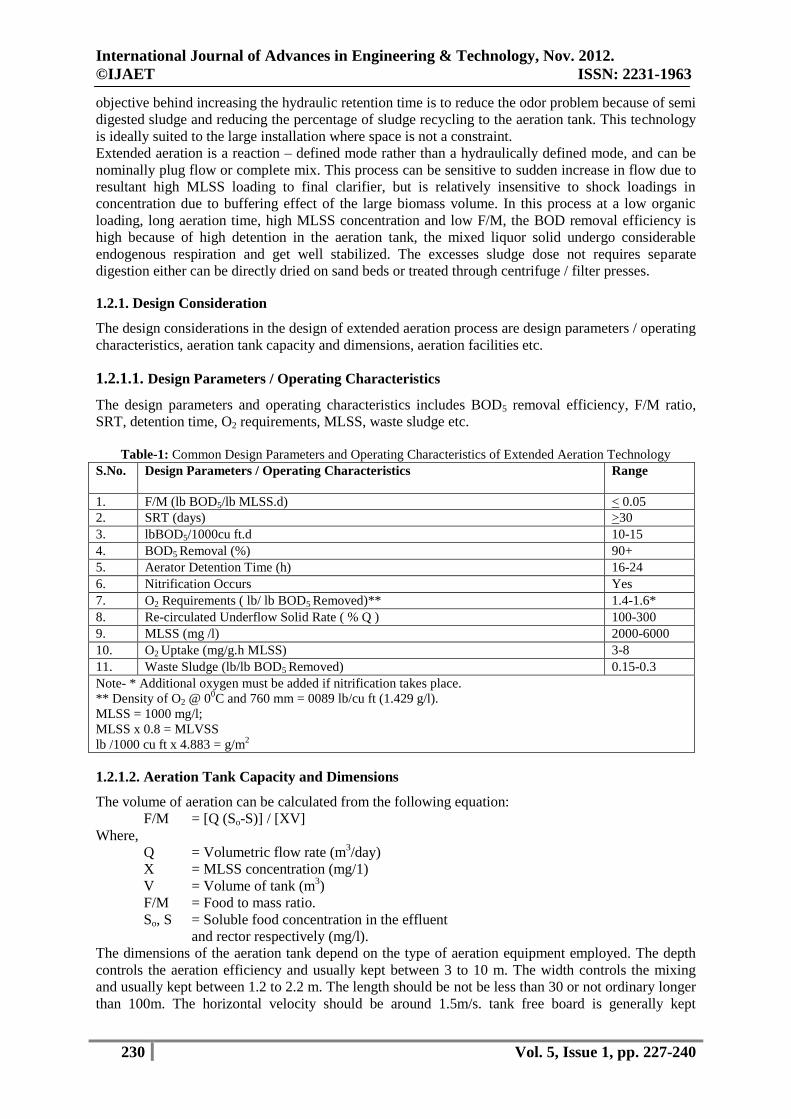
1.2.1. Design Consideration
The design considerations in the design of extended aeration process are design parameters / operating
characteristics, aeration tank capacity and dimensions, aeration facilities etc.
1.2.1.1. Design Parameters / Operating Characteristics
The design parameters and operating characteristics includes BOD5 removal efficiency, F/M ratio,
SRT, detention time, O2 requirements, MLSS, waste sludge etc.
Table-1: Common Design Parameters and Operating Characteristics of Extended Aeration Technology
S.No. Design Parameters / Operating Characteristics Range
1. F/M (lb BOD5/lb MLSS.d) < 0.05
2. SRT (days) >30
3. lbBOD5/1000cu ft.d 10-15
4. BOD5 Removal (%) 90+
5. Aerator Detention Time (h) 16-24
6. Nitrification Occurs Yes
7. O2 Requirements ( lb/ lb BOD5 Removed)** 1.4-1.6*
8. Re-circulated Underflow Solid Rate ( % Q ) 100-300
9. MLSS (mg /l) 2000-6000
10. O2 Uptake (mg/g.h MLSS) 3-8
11. Waste Sludge (lb/lb BOD5 Removed) 0.15-0.3
Note- * Additional oxygen must be added if nitrification takes place.
** Density of O2 @ 00C and 760 mm = 0089 lb/cu ft (1.429 g/l).
MLSS = 1000 mg/l;
MLSS x 0.8 = MLVSS
lb /1000 cu ft x 4.883 = g/m2
1.2.1.2. Aeration Tank Capacity and Dimensions
The volume of aeration can be calculated from the following equation:
F/M = [Q (So-S)] / [XV]
Where,
Q = Volumetric flow rate (m3/day)
X = MLSS concentration (mg/1)
V = Volume of tank (m3)
F/M = Food to mass ratio.
So, S = Soluble food concentration in the effluent
and rector respectively (mg/l).
The dimensions of the aeration tank depend on the type of aeration equipment employed. The depth
controls the aeration efficiency and usually kept between 3 to 10 m. The width controls the mixing
and usually kept between 1.2 to 2.2 m. The length should be not be less than 30 or not ordinary longer
than 100m. The horizontal velocity should be around 1.5m/s. tank free board is generally kept
International Journal of Advances in Engineering & Technology, Nov. 2012.
©IJAET ISSN: 2231-1963
231 Vol. 5, Issue 1, pp. 227-240
between 0.3 and 0.5m. The inlet should be design to maintain a minimum velocity of 0.2 m/s to avoid
the deposition of solids.
1.2.1.3. Oxygen Requirement and Aeration Facilities
Oxygen is required in the extended aeration process for the oxidation of a part of the influent organic
matter and also for the endogenous respiration of micro-organism in the system. The total oxygen
requirement of the process may be formulated as follows:
O2 = [Q (So – Se)] / f] – [1.42 Qw Xr]------ (i)
Where,
f = ratio of BOD5 to ultimate BOD
Q = Volumetric flow rate (m3/day)
So, Se = Soluble food concentration in the influent
and effluent respectively (mg/l).
Qw = Waste activated sludge rate (m3/day)
Xr = MLSS concentration in return sludge
(mg/1) and
1.42 = oxygen demand of biomass (g/g).
The above equation (i) may be expressed as
O2 = [Q (So – Se)] /f]–[1.42(VX / θc)] ---- (ii)
Where,
X = MLSS concentration in reactor (mg/1)
V = Volume of tank (m3)
θc = SRT or Mean cell resident time (day)
Note- The formula does not allow for nitrification but allows only for carbonaceous BOD removal.
The aeration facilities are designed to provide the calculated oxygen demand of the wastewater
against a specific level of dissolved oxygen in the waste water.
Various air diffusing device have been classified as either fine bubble or coarse bubble, with the fine
bubble are more efficient in transferring oxygen.
A diffused-air system consists of diffuser that are submerged in the waste water, header, pipe, air
mains, and the blower and appurtenances through which the air passes. It consists of a tank with
perforated pipes, tubes or diffuser plates, fixed at the bottom to release fine air bubbles from
compressor unit.
Aerator has following advantages:
Aerator are rated based on the amount of oxygen they can transfer to the water under standard
condition of 20ºC, 760 mm Hg barometric pressure and zero D.O.
Aeration removes odour and tested due to volatile gases like hydrogen sulphide and due to
algae and related organisms.
Aeration also oxidize Fe and Mn, increase dissolved oxygen contain in water, remove CO2
and reduces corrosion and remove methane and other flammable gases.
1.2.2 Advantages
Low sludge yields.
Operation is rendered simple due to elimination of primary settling and separate sludge
digestion.
Easy to install.
Require less skilled labour for operation and maintenance (O&M).
Surface aerators in open tanks with long detention periods are not advisable for severe
climates
Efficiency and effluent quality is better than conventional ASP process.
Odor free.
1.2.3 Disadvantages
Oxygen requirement for the processes is higher and running cost is also therefore high.
Loss of pinpoint floc and the tendency to loss solids following low loadings.
International Journal of Advances in Engineering & Technology, Nov. 2012.
©IJAET ISSN: 2231-1963
232 Vol. 5, Issue 1, pp. 227-240
Unable to achieve de-nitrification or phosphorus removal.
Limited flexibility in response to changing effluent requirements.
Long aeration time combined with long sedimentation rate may also result is rising sludge in
the sedimentation tank.
Low temperature insensitive if heat loss is not controlled.
Larger footprint / land area required.
Large energy requirements.
1.3. Sequential Batch Reactor (SBR)
The first notable, but short lived, resurgence of interest in biological treatment occurred in the early
1950s when Porges (1955) and his co-workers first studied batch operation of ASP system for treating
wastewaters. The second resurgence occurred in the 1970s with the effort of Irvine and with his co-
workers investigating the suitability of batch biological processes (Denneis et all, 1979; Irvine et al,
1977; Irvine and Richter, 1976). Around the same period, interest in the batch operated biological
treatment systems surfaced also in Australia (Goronszy, 1979).
It is the same treatment technology like Extended Aeration (E.A.) system but in one tank only where
both biodegradation as well as settling of solids and removal of sludge is done from same tank. It is
also known as a draw-and-fill activated sludge treatment system. The wastewater flows from one tank
to another tank on a continuous basis and virtually all tanks have a predetermined, periodic operating
strategy. Therefore, the SBR is considered a time-oriented and batch process system. The essential
difference between the SBR and the conventional continuous flow activated sludge system is that
SBR carries out functions such as equalization, aeration and sedimentation in a timer rather in a space
sequence.
It consists of a single or multiple reactor tanks operating in parallel. Each operating cycle of a SBR
reactor comprises five distinctive phases, referred to as: FILL, REACT, SETTLE, DRAW and IDLE
phases. The overall control of the system is accomplished with level sensors and timing device or
microprocessor.
One advantage of this orientation is flexibility of operation. The total time in the SBR is used to
establish the size of system and can be related to the total volume of a conventional continuous-flow
facility. As a result, the fraction of time devoted to a specific function in SBR is equivalent to some
corresponding tank in a space oriented system. Therefore the relative tank volumes dedicated to , say
aeration and sedimentation in the SBR can redistributed easily by adjusting the mechanism which
controls the time ( and , therefore share the total volume) planned for either function. In conventional
ASP, the relative tank volume is fixed and cannot be shared or redistributed as easily as in SBR.
Because of the flexibility associated with working in time rather that is space, the SBR can be
operated either as labour – intensive, low- energy, high sludge yield can also be traded off with initial
capital costs. The operational flexibility also allows designers to use SBR to meet many different
treated objectives, including one objective at the time of construction (e.g. BOD and suspended solids
reduction) and another at a later time ( e.g. nitrification / de-nitrification in addition to BOD and
suspended solids removal).
1.3.1 Advantages
Single tank for reaction and settling.
True batch mode of operation & can be operated as a time-based control system allowing
continuous inflow of wastewater during all phases of the cycle.
Respond to flow and load variations.
Quiescent settling and no sludge storages.
Ability to achieve biological oxidation, nitrification, de-nitrification, phosphorus removal and
solid/liquid separation.
Large operational flexibility and automatic possible.
Minimal sludge bulking.
Computer interface technologies, and advanced monitoring instrumentation capability, and
ability to be operated remotely.
Eliminates primary, secondary clarifiers and return sludge pumps
Small footprint required.
International Journal of Advances in Engineering & Technology, Nov. 2012.
©IJAET ISSN: 2231-1963
233 Vol. 5, Issue 1, pp. 227-240
Less labour required when operated automatically and computer controlled.
Odor free technologies.
1.3.2 Disadvantages
Higher energy consumptions
Difficulty to adjust cycle time.
Frequent sludge disposal.
Special decanting and aeration equipments ( can’t use diffusers in reaction tank)
Need to recycle early decant if solids in weir trough.
Setting system sequences can be complex, especially if anoxic de-nitrification is required.
Use of an anaerobic chamber, which is a potential odor source and is an area where corrosion
may occur, even in a concrete tank.
Higher cost because of automation involved.
Skilled labour is required.
1.4. Fluidized Bed Reactor (FBR)
The FBR process is the latest advance in attached growth aerobic biological treatment technology.
FBR employs RING PAC MEDIA, neutrally buoyant bio film carrier elements, to achieve
outstanding BOD/COD removal productivity from a compact bioreactor.
In Fluidized Bed Reactors, the liquid to be treated is pumped through a bed of small media at a
sufficient velocity to cause fluidization. In the fluidized state the media provide a large specific
surface for attached biological growth and allow biomass concentrations in the range 10-40 kg/m3 to
develop (Cooper and Sutton, 1983). For aerobic treatment processes the reactor is aerated. This is
done by recalculating the liquid from the reactor to an oxygenator where air, or possibly oxygen, is
bubbled (Cooper, 1981). To overcome problems related to high re-circulation rates, needed when
there is high oxygen demand in the reactor, the reactor might be aerated directly.
The basis for the use of fluidized bed systems is the immobilization of bacteria on solid surfaces.
Many species of bacteria (and also other microorganisms) have the ability for adhering to supporting
matrices.
In this process, a volume of Ring Pac media is immersed in water and is fluidized (kept in constant
motion) through the movement of gas and liquid in the treatment reactor. As the media supports a
biomass concentration several times that achievable in activated sludge systems, treatment is
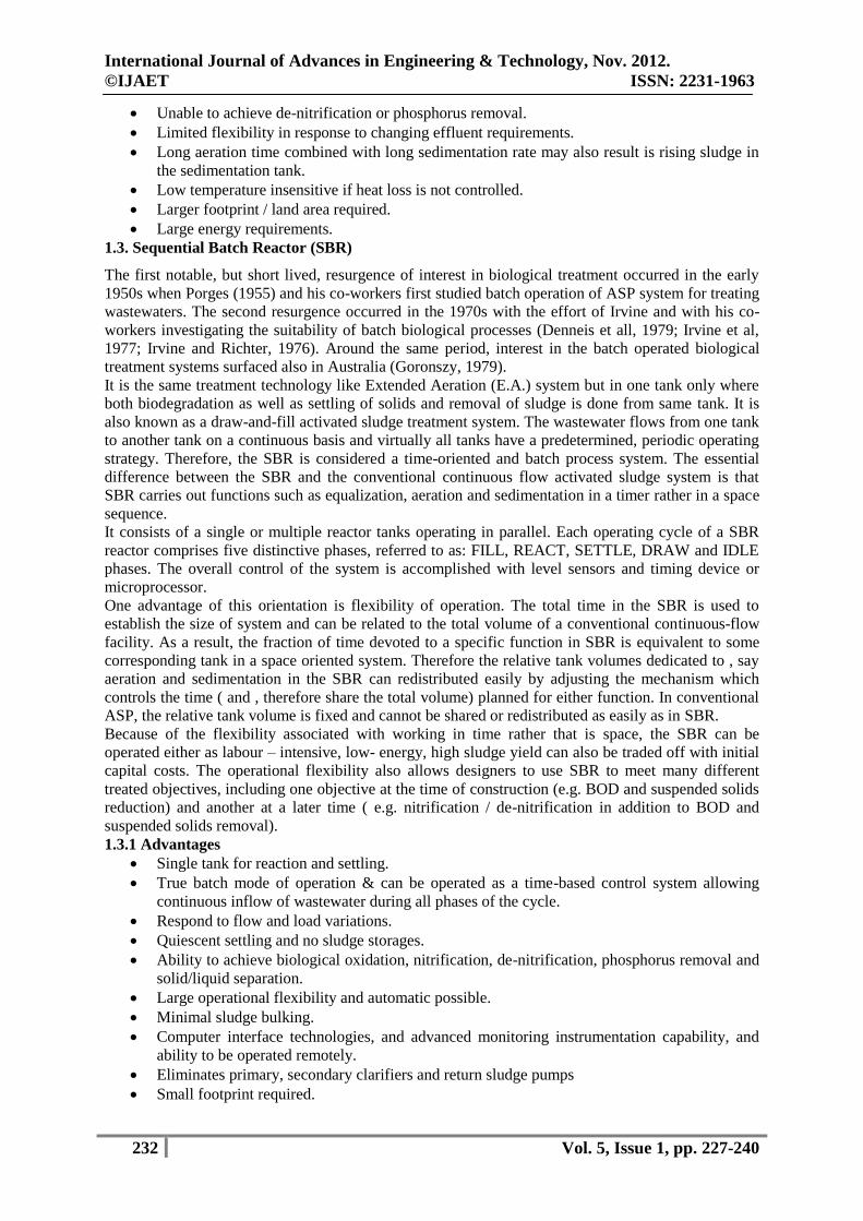
significantly more productive. Refer figure-1 for ring pac bio-media.
Figure-1: Ring Pac Bio-Media for FBR reactors
The neutrally buoyant plastic media within each aeration tank provides a stable base for the growth of
a diverse community of microorganisms. PVC media has a very high surface-to-volume ratio,
allowing for a high concentration of biological growth to thrive within the protected areas of the
media. The FBR process enables self-sustaining biological treatment; the need to periodically waste
sludge and the requirement to supply a dilute return activated sludge to maintain an appropriate food-
to-microorganism (F/M) ratio is eliminated.
In addition, the excess biomass is automatically sloughed off in the process, maintaining a highly
active biomass.
1.4.1. Advantages
The FBR requires very less hydraulic retention time (HRT) compared to an extended aeration
or activated sludge process to perform the same BOD reduction duty.
High resident biomass concentration, intense mass transfer conditions and aggressive
biomass-sloughing action enable the process to rapidly respond to variations in process load.
International Journal of Advances in Engineering & Technology, Nov. 2012.
©IJAET ISSN: 2231-1963
234 Vol. 5, Issue 1, pp. 227-240
The mechanical simplicity, flow-through nature of the process and no sludge problems all
result in an almost operator-free process.
FAB reactor is hybrid reactor where attached growth and suspended growth activity take
place simultaneously.
The BOD removal rate continues to increase with loading rate even at loading rates in excess.
Less operation and maintenance cost during plant operations.
Less footprint area required for installation.
Efficient and reliable technology.
1.4.2 Disadvantages
Less effective during large variation in influent wastewater.
Constant monitoring of MLSS is required.
More chances of septic conditions due to power failure.
Moderate power consumption.
1.5 Submerged Aeration Fixed Film (SAFF) Reactor
An innovation that has been implemented in recent years is the fixed film media into activated sludge
reactors to improve performance and in some cases to minimize expansion of existing facilities. In
plants where nitrification and de-nitrification is practiced, nitrification is usually the rate-limiting step
and the media is placed in the aerobic zone to enhance nitrification at low temperatures.
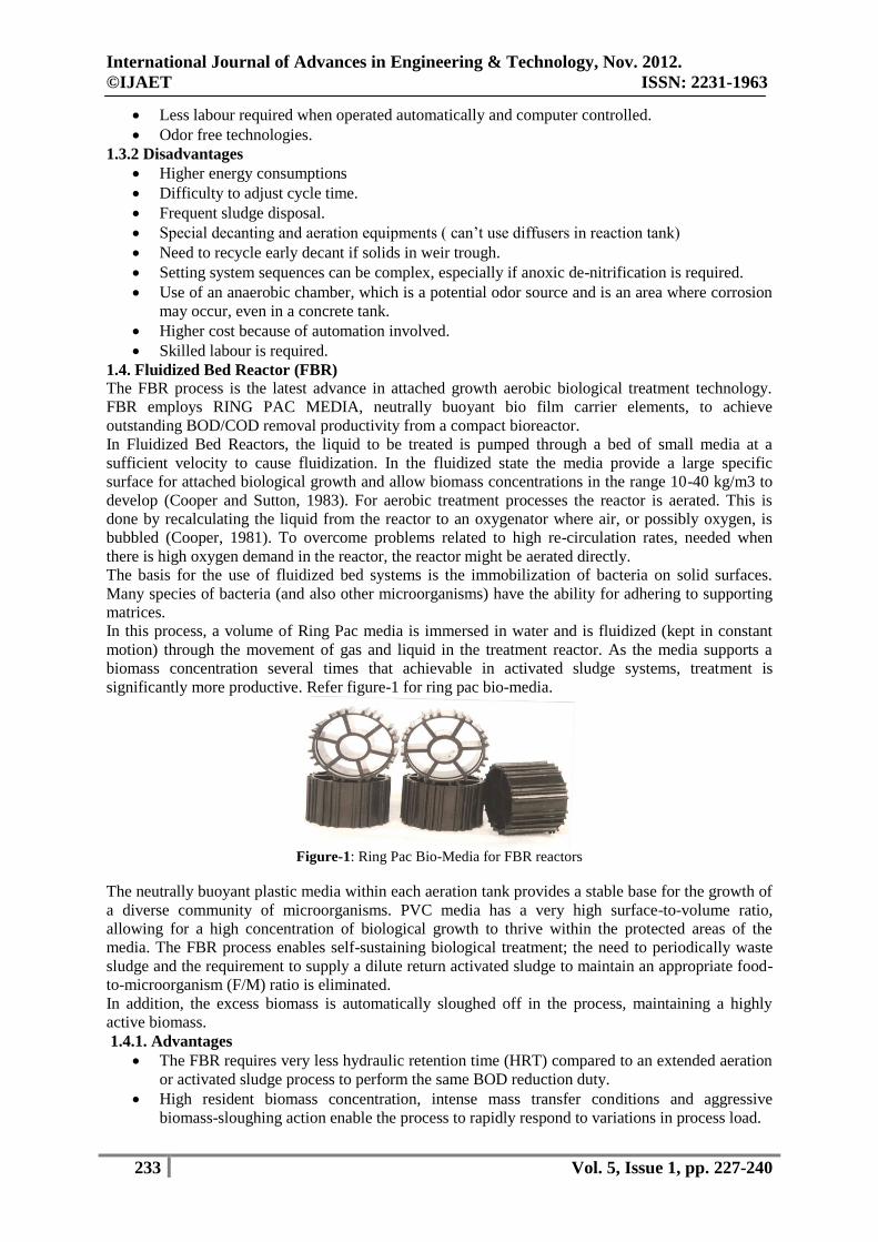
It is based on aerobic attached growth process and used in the secondary treatment of wastewater
treatment plant. In this process raw sewage is introduced into the SAFF Reactor where for attached
growth process takes place containing contains polymer based bio-media. The aerobic environment in
the SAFF is achieved by the use of fine bubble diffused aeration equipments, which also serves to
maintain the mixed liquor in a completely mixed regime. The mixture of new cells and old cells
overflows into a secondary sedimentation tank where the cells are separated from the treated
wastewater. A portion of the settled cells is recycled using the horizontal, non-clog, and flooded
pumps to maintain the desired concentration of organisms in the SAFF reactor and the remaining
portion is wasted to aerobic sludge digester-cum-thickener tank for further sludge treatment. Refer
figure-2 for general sketch for SAFF reactor system.
Figure-2: General sketch for SAFF reactor
SAFF technology for optimum performance and dependability. Using reliable, cost effective and
energy efficient blower for aeration are with an integral flow management system and enter the
biological treatment stage where it is aerated with fine bubble membrane diffuser. The continuous
supply of oxygen together with the incoming food sources encourage microorganism to grow on the
surface of the submerged media, convening the waste water in to CO2 and water in the process. Media
of SAFF is providing more surface area for microorganism to grow. Excess micro-organism (known
as humus solids) that flows out of the biological treatment stage is separated from the final effluent in
another settlement stage.
1.5.1. Advantages
No constant monitoring of MLSS required thus making it user friendly.
No chance of occurring septic conditions due to power failure as it sustains microbial growth
under irregular power supply conditions.
Reduced overall volume due to multistage.
International Journal of Advances in Engineering & Technology, Nov. 2012.
©IJAET ISSN: 2231-1963
235 Vol. 5, Issue 1, pp. 227-240
Reduced civil constructions.
Less maintenance as there is no moving parts.
Low power consumption due to high oxygen transfer.
Better oxygen transfer.
Less sludge generation hence reduced problem of sludge disposal.
Low operating costs due to absence of sludge recycling.
The fixed-film process will continually slough off outer layer(s) of dead bio film and continue
to produce new microorganisms to meet the organic load.
1.5.2. Disadvantages
Little higher footprint compared to FBR technology.
Excess sludge in the SAFF reactor can clog the bio-media, therefore continuous monitoring of
MLSS is required.
1.6. Membrane Bio-Reactor (MBR)
It is latest technology has been using very widely to treat domestic wastewater. In this process the
treatment is using by synthetic membranes or diffusion process through membrane.
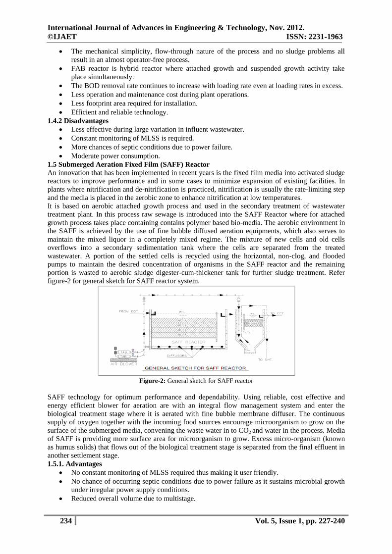
It is proposed to use Membrane Bio-Reactor (MBR) system working on the principle of filtration of
activated sludge through the concept of using flat sheet type or hollow fibre type submerged
membrane modules in bioreactors. The membranes in a MBR system are made from polymeric
organics (PVDF, PE or PES) and assembled into units (modules, cassettes, stacks) with high packing
density. Raw wastewater pre-treatment is important to sustain stable MBR performance and fine
screening is essential operation.
The use of Membrane Bio-Reactors (MBRs) in municipal wastewater treatment has grown widely in
the past decades. The MBR technology combines conventional activated sludge treatment with low-
pressure membrane filtration, thus eliminating the need for a clarifier or polishing filters. The
membrane separation process provided a physical barrier to contain microorganisms and assures
consistent high quality reuse water. The ability to treat raw wastewater for reuse provides a new,
reliable, drought-proof supply of water that can be benefit to communities.
Figure-3: General sketch for MBR reactor
1.6.1 Advantages
MBR is capable of meeting the most stringent effluent water quality standards.
Membrane modules are back-flushable
Requires cleaning only once in 3 to 6 months.
Yield 60-80% less sludge than conventional system.
Compact design- footprint 75% smaller than conventional.
Possibility of direct and indirect water reuse.
Highly space efficient.
High quality effluent in a greatly simplified process.
No secondary clarifier, virtually no effluent suspended solids, no RAS recycling.
Maintain high MLSS
Easily automated and instrumented to measure performance.
It allows systems to be remotely operated and monitored, thus significantly reducing operator
attendance.
International Journal of Advances in Engineering & Technology, Nov. 2012.
©IJAET ISSN: 2231-1963
236 Vol. 5, Issue 1, pp. 227-240
Sludge can be wasted directly from aeration tank.
1.6.2 Disadvantages
Limited tolerance for abrasive and stringy materials, such as grit, hair and fibrous material.
Accumulation of solids and sludge between membrane fibres and plates can clog/damage the
membrane tube openings.
Membrane fouling.
Higher energy consumption to overcome trans-membrane resistance and to prevent fouling
using aeration etc.
Very high aeration requirements.
Dual aeration system for mixing and to prevent fouling.
Time-consuming membrane cleaning procedure.
High capital costs for membrane system.
Extra power requirements for vacuum on micro filter.
Waste activated sludge is not thickened- larger volume to solids processing.
Broken membranes result in low effluent quality.
II. COMPARISON OF TREATMENT TECHNOLOGIES
Wastewater treatment technologies can be classified under three categories based on performance
parameters, land requirements, energy demand:
2.1. Category-I:
Good performance, low energy requirement, low resource requirement and associated costs, high land
requirement (BOD < 30, TSS <30).
2.2 Category-II:
Good performance, high energy requirement, high resource requirement and associated costs,
moderately low land requirement (BOD < 30, TSS <30).
2.3. Category-II (Improved Version):
Very good performance, very high energy requirement, very high resource requirement and associated
costs, low land requirement (BOD < 20, TSS <20).
2.4. Category-II (Further Improved Version):
Very good performance, very high energy requirement, very high resource requirement and associated
costs, low land requirement (BOD < 10, TSS <10).
2.5 Category-III:
Moderate performance, moderate energy requirement, moderate resource requirement and associated
costs, moderate low land requirement (BOD < 30, TSS <30).
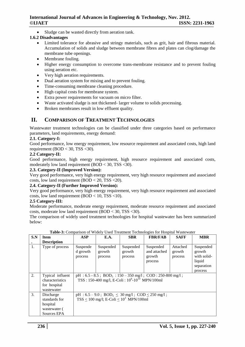
The comparison of widely used treatment technologies for hospital wastewater has been summarized
below:
Table-3: Comparison of Widely Used Treatment Technologies for Hospital Wastewater
S.N
.
Item
Description
ASP E.A. SBR FBR/FAB SAFF MBR
1. Type of process Suspende
d growth
process
Suspended
growth
process
Suspended
growth
process
Suspended
and attached
growth
process
Attached
growth
process
Suspended
growth
with solid-
liquid
separation
process
2.
Typical influent
characteristics
for hospital
wastewater
pH : 6.5 - 8.5 ; BOD5 : 150 – 350 mg/l ; COD : 250-800 mg/l ;
TSS : 150-400 mg/l, E-Coli : 106-10
10 MPN/100ml
3.
Discharge
standards for
hospital
wastewater (
Sources EPA
pH : 6.5 – 9.0 ; BOD5 < 30 mg/l ; COD < 250 mg/l ;
TSS < 100 mg/l; E-Coli < 103 MPN/100ml
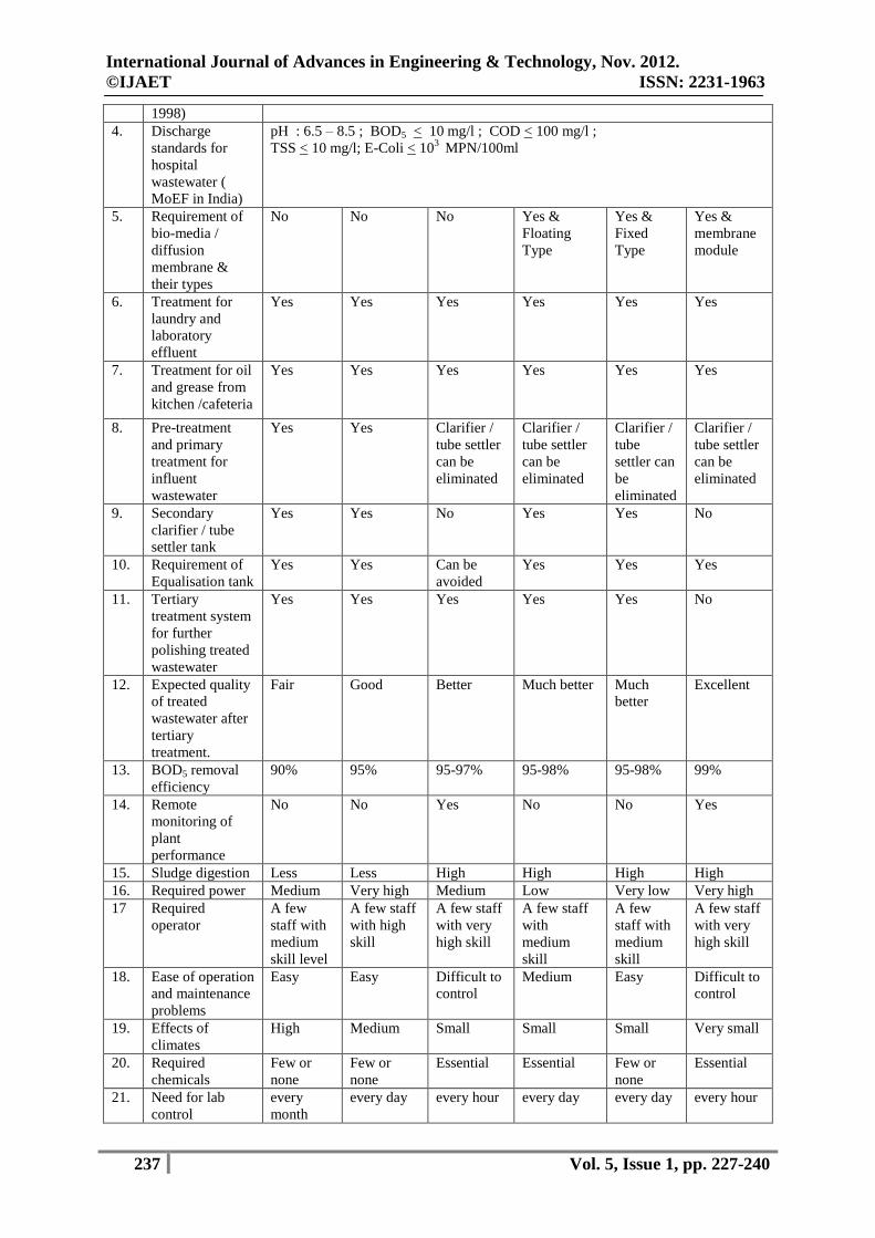
International Journal of Advances in Engineering & Technology, Nov. 2012.
©IJAET ISSN: 2231-1963
237 Vol. 5, Issue 1, pp. 227-240
1998)
4.
Discharge
standards for
hospital
wastewater (
MoEF in India)
pH : 6.5 – 8.5 ; BOD5 < 10 mg/l ; COD < 100 mg/l ;
TSS < 10 mg/l; E-Coli < 103 MPN/100ml
5. Requirement of
bio-media /
diffusion
membrane &
their types
No No No Yes &
Floating
Type
Yes &
Fixed
Type
Yes &
membrane
module
6. Treatment for
laundry and
laboratory
effluent
Yes Yes Yes Yes Yes Yes
7. Treatment for oil
and grease from
kitchen /cafeteria
Yes Yes Yes Yes Yes Yes
8. Pre-treatment
and primary
treatment for
influent
wastewater
Yes Yes Clarifier /
tube settler
can be
eliminated
Clarifier /
tube settler
can be
eliminated
Clarifier /
tube
settler can
be
eliminated
Clarifier /
tube settler
can be
eliminated
9. Secondary
clarifier / tube
settler tank
Yes Yes No Yes Yes No
10. Requirement of
Equalisation tank
Yes Yes Can be
avoided
Yes Yes Yes
11. Tertiary
treatment system
for further
polishing treated
wastewater
Yes Yes Yes Yes Yes No
12. Expected quality
of treated
wastewater after
tertiary
treatment.
Fair Good Better Much better Much
better
Excellent
13. BOD5 removal
efficiency
90% 95% 95-97% 95-98% 95-98% 99%
14. Remote
monitoring of
plant
performance
No No Yes No No Yes
15. Sludge digestion Less Less High High High High
16. Required power Medium Very high Medium Low Very low Very high
17 Required
operator
A few
staff with
medium
skill level
A few staff
with high
skill
A few staff
with very
high skill
A few staff
with
medium
skill
A few
staff with
medium
skill
A few staff
with very
high skill
18. Ease of operation
and maintenance
problems
Easy Easy Difficult to
control
Medium Easy Difficult to
control
19. Effects of
climates
High Medium Small Small Small Very small
20. Required
chemicals
Few or
none
Few or
none
Essential Essential Few or
none
Essential
21. Need for lab
control
every
month
every day every hour every day every day every hour
International Journal of Advances in Engineering & Technology, Nov. 2012.
©IJAET ISSN: 2231-1963
238 Vol. 5, Issue 1, pp. 227-240
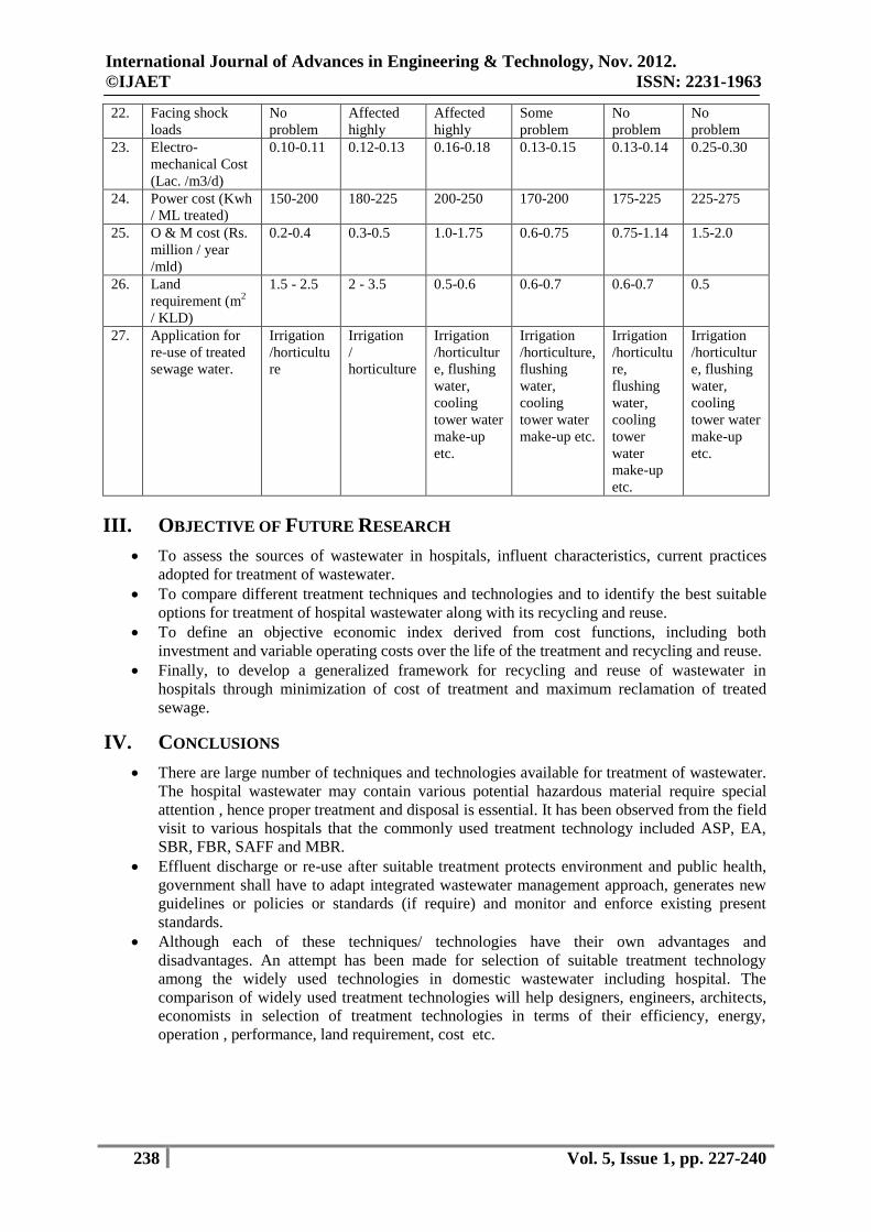
22. Facing shock
loads
No
problem
Affected
highly
Affected
highly
Some
problem
No
problem
No
problem
23. Electro-
mechanical Cost
(Lac. /m3/d)
0.10-0.11 0.12-0.13 0.16-0.18 0.13-0.15 0.13-0.14 0.25-0.30
24. Power cost (Kwh
/ ML treated)
150-200 180-225 200-250 170-200 175-225 225-275
25. O & M cost (Rs.
million / year
/mld)
0.2-0.4 0.3-0.5 1.0-1.75 0.6-0.75 0.75-1.14 1.5-2.0
26. Land
requirement (m2
/ KLD)
1.5 - 2.5 2 - 3.5 0.5-0.6 0.6-0.7 0.6-0.7 0.5
27. Application for
re-use of treated
sewage water.
Irrigation
/horticultu
re
Irrigation
/
horticulture
Irrigation
/horticultur
e, flushing
water,
cooling
tower water
make-up
etc.
Irrigation
/horticulture,
flushing
water,
cooling
tower water
make-up etc.
Irrigation
/horticultu
re,
flushing
water,
cooling
tower
water
make-up
etc.
Irrigation
/horticultur
e, flushing
water,
cooling
tower water
make-up
etc.
III. OBJECTIVE OF FUTURE RESEARCH
To assess the sources of wastewater in hospitals, influent characteristics, current practices
adopted for treatment of wastewater.
To compare different treatment techniques and technologies and to identify the best suitable
options for treatment of hospital wastewater along with its recycling and reuse.
To define an objective economic index derived from cost functions, including both
investment and variable operating costs over the life of the treatment and recycling and reuse.
Finally, to develop a generalized framework for recycling and reuse of wastewater in
hospitals through minimization of cost of treatment and maximum reclamation of treated
sewage.
IV. CONCLUSIONS
There are large number of techniques and technologies available for treatment of wastewater.
The hospital wastewater may contain various potential hazardous material require special
attention , hence proper treatment and disposal is essential. It has been observed from the field
visit to various hospitals that the commonly used treatment technology included ASP, EA,
SBR, FBR, SAFF and MBR.
Effluent discharge or re-use after suitable treatment protects environment and public health,
government shall have to adapt integrated wastewater management approach, generates new
guidelines or policies or standards (if require) and monitor and enforce existing present
standards.
Although each of these techniques/ technologies have their own advantages and
disadvantages. An attempt has been made for selection of suitable treatment technology
among the widely used technologies in domestic wastewater including hospital. The
comparison of widely used treatment technologies will help designers, engineers, architects,
economists in selection of treatment technologies in terms of their efficiency, energy,
operation , performance, land requirement, cost etc.
International Journal of Advances in Engineering & Technology, Nov. 2012.
©IJAET ISSN: 2231-1963
239 Vol. 5, Issue 1, pp. 227-240
ACKNOWLEDGEMENT
I sincerely would like to Thanks University Jamia Millia Islamia, New Delhi, India for their support
as and when required.
REFERENCES
[1]. American Members Technology Association (ATMA), (2007). FS-13.
[2]. Caro Estrada, R. et. al., “ Comparison Between MBR and Actiavetd Sludge Technologies for Wastewater
Reclamation and Reuse”.
[3]. Chudoba, J.Ottova, V. Nad Mandera, V. (1973). Control of activated sludge filamentous bulking: effect of
hydraulic regime or degree of mixing in aeration tank. Waste Research, 8:1163. (this paper details the
effect of hydraulic mixing in SBR systems).
[4]. Cooper, P.F., 1981. The use of biological fluidised beds for the treatment of domestic and industrial
wastewaters.chem.eng.371, 373-376.
[5]. Cooper, P.F., Sutton, D.M., 1983. Treatment of wastewaters using biological fluidised beds chem.eng.392,
392.
[6]. Deegan, A.M. et. al. (2011), “ Treatment options for wastewater effluent from pharmaceutical companies”.
Inst.J. Environ. Sci.Tech., 8 (3), 649-666.
[7]. Dennis, R.W. and Irvine, R.L. (1979). Effect of fill: react ratio on sequencing batch biological reactors.
Journal Water Pollution Control Federation, 51(2), 255-263. (This paper describes the performance of SBR
in various operation models).
[8]. Eckenfelder W.Wesley, Industrial Water Pollution Control, Third Edition, Environmental Engineering
Series, McGraw-Hill International Editions.
[9]. El Nadi El Hosseiny Dr.Mohamed (2005)” Wastewater Treatment Design Report”, Report No.8, pp-12,
14).
[10]. Goronszy, M.C. (199). Intermittent operation of extended aeration process for small systems. Journal
Water Pollution Control Federation, 51(2), 274-287. (this paper describes the use of SBR in Australia).
[11]. Irvine R.L. and Richter, R.O. (1976).Computer simulation and design of sequencing batch reactors,
Proceedings of 31st Industrial Waste Conference, Purdue University, West Lafayette, Indiana, USA, P.182
( this paper describes the development and operation of SBR).
[12]. Irvine, R.L. Fox, T.P., and Richter, R.O. (1977). Investigations of fill and batch periods of sequencing
batch reactors, water research, 11,713-717 (this paper describes the development and operation of SBR).
[13]. Jaldhara Technologies Private Limited , Technical Seminar (2012) “Introduction to Next Generation
Technology for Sewage , Wastewater & Effluent Treatment”.
[14]. Jenkins, D., Richard, M.G., and Daigger, G.T. (1993) Manual on the Causes and Control of Activated
Sludge Bulking and Foaming, 2nd
ed. Boca Raton: Kewis Publishers.
[15]. Jordening, Hans-Joachim, Buchholz, Klaus,” 24 Fixed Film Stationary Bed and Fludized Bed Reactors”.
[16]. Leitao, R.C. et. al.(2006), “ The effects of operational and envrinmental variations on anaerobic
wastewater treatment systems: A review”. Bioresource Technology 97. pp. 1105-1118.
[17]. Mahvi, A.H.(2008)., “Sequencing Baatch Reactor:A promising technology in wastewater treatment:, Iran.
J. Environ. Health. Sci. Eng., Vol. 5, No. 2, pp. 79-90.
[18]. Melin, T. et. al., (2005), “ Membrane bioreactor technology for wastewater treatment and
reuse”.Desalination 187. pp 271-282.
[19]. Mesdaghinia AR, Naddfi K, Nabizadeh R, Saeedi R, Zamanzadeh M (2009), Wastewater Characteristics
and Appropriate Method for Wastewater Management in the Hospitals, Vol.38, No.1, pp.34-40.
[20]. Miron, F. Anton.et. al, (1997) “Wastewater Treatment Plant Design by A Joint Committee of the Water
Pollution Control Federation and the American Society of Civil Engineers”.
[21]. Nicolella C., Loosdrecht van M.C.M, Heijmen J.J. (2000), Wastewater treatment with particulate bio film
reactors, Journal of Biotechnology 80, pp. 1-33.
[22]. Pauwels B, Verstraete W (2006), The treatment of hospital wastewater: an appraisal, Journal of Waste and
Health, 044: 406-413.
[23]. Porges, N. (1955) Waste treatment by optimal aeration-theory and practice in dairy waste disposal.
[24]. Rezaee A, Ansari M, Khavanin A, Sabzali A, Aryan M.M., Hospital (2005) Wastewater Treatment Using
an Integrated Anaerobic Aerobic Fixed Film Bioreactor, American Journal of Environmental Science 1
(4): 259-263.
[25]. Schroeder, E.D. (1982). Design of sequencing batch reactor activated sludge processes. In Civil
Engineering for practicing and design engineers 2:33-34. (this chapter gives design guidance for SBR).
[26]. Shah, Shwetal. (2011) Initial Proposal – Technical Solution for Sewage Waste Treatment and Reuse.
International Journal of Advances in Engineering & Technology, Nov. 2012.
©IJAET ISSN: 2231-1963
240 Vol. 5, Issue 1, pp. 227-240
[27]. Sperling, Marcos von, Chernicharo, Carlos Augusto de Lemos, “ I-078- A comparison between wastewater
treatment processes in terms of compliance with effluent quality standards”.
[28]. Tehobanoglous George, Burton Franklin L., Stensel H. D. (2007). Wastewater Engineering: Treatment,
Disposal, Reuse, Metcalf and Eddy, Inc. 4th Ed. McGraw-Hill, New York.
[29]. Topare, Niraj S., Attar, S.J., Manfe, Mosleh M. (2011), “ Sewage / Wastewater Treatment Technologies :
A Review”. Sci. Revs. Chem. Commun. :1 (1), pp. 18-24.
[30]. Vigneswaran, S., Sundaravadival, M., and Chaudhary, D.S., “Sequencing Batch Reactors: Principles,
Design / Operations and Case Studies”...
[31]. Water Environment Association. (1987) Activated Sludge, Manual of Practice # 9.
[32]. Web address:
(i) www.amtaorg.org
(ii) http://trade.indiamart.com/details.mp?offre=1777676912 (iii) http://trade.indiamart.com/details.mp?offre=1777676912 (iv) http://www.who.int/water_sanitation_health/resourcesquality/wpcchap3.pdf
[33]. “Waste-Water Treatnment Technologies : A General Review”. United Nations, New York, 2003.
[34]. Zhou, H., Smith, D. W. (2002), “Advanced technologies in water and wastewater treatment”.J. Environ.
Eng.Sci. 1: pp. 247-264.
AUTHORS
Jafrudeen is currently working as Director - Technical, M/s. Rivulet Engineering
Consultancy Private Limited., Delhi, India and Technical Associate (PHE, FPS, WWTS)
at M/s. ABL Hospitech Pvt. Ltd., Delhi, India. He also is pursuing Ph.D. (Environmental
Science and Engineering) from Jamia Millia Islamia, New Delhi. Prior to this, he was
working in the field of design, execution and operations of water and wastewater
treatment systems with reputed firm M/s. Enhanced WAPP Systems Pvt. Ltd. He holds
Bachelor’s Degree in Chemical Engineering from C.R.S.C.E. (Now D.C.R.U.S.T),
Murthal, Haryana, India. He also holds Master’s Degree in Environmental Science and Engineering (Gold
Medallist) from Jamia Millia Islamia, New Delhi, India. He has been working in the field of water and
wastewater since 2003.