Embed Size (px)
Citation preview
www.environment-agency.gov.uk
Guidance on gas treatmenttechnologies for landfill gas engines
Landfill directive
LFTGN 06
Lfd
www.environment-agency.gov.uk
The Environment Agency is the leading public body protecting and
improving the environment in England and Wales.
It’s our job to make sure that air, land and water are looked after by
everyone in today’s society, so that tomorrow’s generations inherit a
cleaner, healthier world.
Our work includes tackling flooding and pollution incidents, reducing
industry’s impacts on the environment, cleaning up rivers, coastal
waters and contaminated land, and improving wildlife habitats.
Published by:
Environment AgencyRio House, Waterside Drive, Aztec WestAlmondsbury, Bristol BS32 4UDTel: 08708 506506
© Environment Agency August 2004
All rights reserved. This document may be reproduced with prior permission of the Environment Agency.
This report is printed on Cyclus Print, a 100% recycled stock,which is 100% post consumer waste and is totally chlorine free.Water used is treated and in most cases returned to source inbetter condition than removed.
Dissemination Status:Internal: Released to RegionsExternal: Public Domain
Research Contractor:This document was based on research undertaken as R&DProject P1-330 by:LQM Ltd, Berwick Manley Associates Ltd, Diesel Consult,Landfills + Inc and Golder Associate (UK) Ltd.
Environment Agency’s Project Team:The following were involved in the production of this guidance:
Chris Deed Head Office (Project Manager)Jan Gronow Head OfficeAlan Rosevear ThamesPeter Braithwaite Head OfficeRichard Smith Head OfficePeter Stanley Wales
Statement of Use
This guidance is one of a series of documents relating to themanagement of landfill gas. It is issued by the EnvironmentAgency and the Scottish Environment Protection Agency (SEPA)to be used in the regulation of landfills. It is primarily targeted atregulatory officers and the waste industry. It will also be of inter-est to contractors, consultants and local authorities concernedwith landfill gas emissions. Environment Agency and SEPA offi-cers, servants or agents accept no liability whatsoever for any lossor damage arising from the interpretation or use of the informa-tion, or reliance on views contained herein. It does not constitutelaw, but officers may use it during their regulatory and enforce-ment activities. Any exemption from any of the requirements oflegislation is not implied.
Throughout this document, the term 'regulator' relates jointly tothe Environment Agency and the Scottish EnvironmentProtection Agency. SEPA does not necessarily support and is notbound by the terms of reference and recommendations of otherdocumentation mentioned in this guidance, and reserves theright to adopt and interpret legislative requirements and appro-priate guidance as it sees fit. The term 'Agency' should thereforebe interpreted as appropriate.
Environment Agency Guidance on gas treatment technologies for landfill gas engines 1
Executive summary
The bulk of emissions from modern landfills are through the landfill gasmanagement system and the landfill surface.The gas management systemmay include enclosed flares and/or utilisation plant, which destroy asignificant proportion of the methane and volatile organic compoundswithin landfill gas, but can produce additional combustion products. Thecomposition of landfill gas engine emissions depends on the gas supply,the design of the generating set and the engine management system.
This guidance explains the technical background for landfill gas clean-up methods and describes a consistentapproach for determining the level of clean-up required. It sets out an assessment procedure that follows a costbenefit analysis approach to deciding whether gas clean-up is necessary or practicable. The assessmentprocedure has the following six steps:
● define the objective of the assessment and the options for pollution control;● quantify the emissions from each option;● quantify the environmental impacts of each option;● compare options to identify the one with the lowest environmental impact;● evaluate the costs to implement each option; ● identify the option that represents the cost-effective choice or best available technique.
If these steps are followed, the decision procedure for selecting or rejecting a particular clean-up technology istransparent and an audit trail is apparent. The guidance also considers a number of case studies, which arereported in Environment Agency R&D Technical Report P1-330/TR.
This guidance will be used when:
● specifying conditions in Pollution Prevention and Control (PPC) permits (including landfill permits) that provide all appropriate measures to be taken against pollution and to limit emissions and impact on the environment;
● setting appropriate conditions in waste management licences.
Gas clean-up is a multi-stage operation that can help reduce environmental emissions and reduce enginemaintenance costs. It involves both financial and environmental costs for the operator, but it improves the gassupply to conform to the requirements laid down by the engine manufacturer and/or to achieve emissionstandards set by the regulator.
Pretreatment processes fall into two groups:
● primary pretreatment processes aimed at de-watering and particulate removal (common to all landfills with gas collection and combustion facilities)
● secondary pretreatment processes aimed at removing a percentage of specific components of the supply gas, e.g. halogens, sulphur or siloxane compounds.
Combustion treatment technologies are available for:
● in-engine technology to treat the effects of siloxanes and for nitrogen oxide reduction; ● post-combustion processes to reduce carbon monoxide, unburnt hydrocarbons, hydrogen chloride and
hydrogen fluoride emissions.
Changes in air quality regulation and the tightening of emissions from all processes mean that landfill gasengine operators may need to consider gas clean-up technologies in their applications for PPC permits(including landfill permits).
ContentsExecutive summary 1
1 Introduction 4
1.1 Target audience 4
1.2 Structure of this document 5
1.3 Technical background 5
1.4 Policy background 7
2 Gas quality, emission standards and operational requirements 10
2.1 Introduction 10
2.2 Engine manufacturers’ specifications 10
2.3 Destruction efficiencies of gas engines 16
2.4 Engine emissions and their significance 17
2.5 Crankcase emissions 18
3 Decision process: assessing the use of clean-up technologies 19
3.1 Clean-up approaches 19
3.2 Potential for substitute natural gas as a fuel for landfill gas engines 22
3.3 The framework for assessing gas clean-up 22
3.4 Collating basic information for the cost appraisal 23
3.5 How to perform a cost benefit analysis for gas clean-up 25
4 Primary pretreatment technologies 33
4.1 Water/condensate knockout 33
4.2 Particulate filtration 36
4.3 Dealing with wastes from primary clean-up processes 36
5 Secondary pretreatment technologies 37
5.1 Introduction 37
5.2 Hydrogen sulphide pretreatment 37
5.3 Pretreatment of halogenated organics 39
5.4 Siloxane pretreatment 46
5.5 Developmental technologies 47
5.6 Dealing with wastes from secondary clean-up processes 48
Environment Agency Guidance on gas treatment technologies for landfill gas engines2
6 Engine management, in-engine and exhaust treatment 49
6.1 Introduction 49
6.2 Gas engines and their operation 49
6.3 Engine management systems and NOx 50
6.4 In-engine treatments 50
6.5 Exhaust after-treatments 52
7 Conclusions 54
Glossary and acronyms 55
References 61
Index 63
Environment Agency Guidance on gas treatment technologies for landfill gas engines 3
Introduction
This guidance document considers the availability andcost of clean-up technologies for:
● landfill gas pre-combustion● in-combustion and engine management system
techniques● post-combustion exhaust gas.
It sets out the formal decision-making processes fordeciding whether the use of gas clean-up technologies(including the use of engine management systems) is acost-effective solution to managing combustionemissions from landfill gas engines.
Post-process emissions management does not addressthe issue of managing the emissions from the point oforigin or source term (i.e. the landfill). Pretreatmentprior to combustion can have significant benefits to thegas plant in terms of reducing corrosive damage. Post-combustion treatment will achieve some improvementin environmental emissions, but they do not benefitengine operation or maintenance regimes.
1.1 Target audience
The guidance document is aimed primarily at Agencystaff with responsibility for the regulation of landfill gasemissions from utilisation plant. The guidance should beapplied only if emissions:
● exceed the current emission threshold values for individual components of the exhaust gases (see Table 2.3 and Environment Agency, 2004a);
● could pose a risk to an identified receptor following a site-specific risk assessment (see Section 2 and Environment Agency, 2004a).
The guidance should be used to evaluate whether thesecondary clean-up of landfill gas is necessary andpractical on the grounds of cost versus environmentalbenefit.
This guidance is also intended to be help the wastemanagement industry, gas utilisation plant operatorsand other interested parties assess the merits, costs andbenefits of gas clean-up to minimise emissions (and/orachieve emission standards) and to maximise engine
component life. Operators should use the stagedassessment process if asked to do so by the regulator.
This is one of a series of linked documents that supportthe overarching document Guidance on themanagement of landfill gas (Environment Agency,2004b). The full series comprises:
● Guidance for monitoring trace components in landfill gas
● Guidance on landfill gas flaring● Guidance for monitoring enclosed landfill gas
flares● Guidance for monitoring landfill gas engine
emissions● Guidance for monitoring landfill gas surface
emissions● Guidance on gas treatment technologies for landfil
gas engines.
Gas clean-up needs to be assessed by balancing thelikely cost against benefits to the environment and forengine maintenance. Inevitably, this assessment will besite-specific. The guidance describes the availabletechnologies and their application to landfill gastreatment.
Due to the low take-up of these technologies and thelack of any demonstrable revenue performance fromearly clean-up methods, estimates of capital andoperating costs for gas engines are poor. It has beenpossible to estimate capital costs for some technologiesand to calculate either the cost per tonne of thepollutant abated or the approximate annual cost ofrunning a clean-up plant for a 1 MWe gas engine. Asmore technologies become routinely available, a moredetailed cost benefit analysis (CBA) should be possibleto determine the best solution for a particular problem.
Clean-up costs should be obtained on a site-specificbasis for a number of suitable technologies and a CBAperformed as described in Section 3 of this guidanceand in more detail in IPPC Horizontal Guidance NoteH1 (Environment Agency, 2002a). The CBA will give thecosts versus the potential environmental and otherbenefits of managing and reducing engine emissions byusing such technologies. Once the cost per tonne of
Environment Agency Guidance on gas treatment technologies for landfill gas engines4
1

pollutant abated (capital and operating costs) has beencalculated, judgement can be made on whether theprocess is cost-effective based on the Agency’s interimrecommendations of clean-up cost thresholds.
1.2 Structure of this document
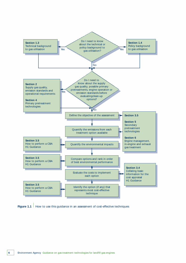
This guidance is accessible at various levels, but isintended to be used as shown in Figure 1.1.
Some background information may be required inorder to understand the setting in which the assessmentprocess is carried out. This is provided in:
● Section 1.4 (technical background)● Section 1.5 (policy background)● Section 2. This describes how the supply gas
quality may affect emissions and explains how manufacturers specify gas supply standards to help maintain the gas engine in good operational condition between service intervals. Such standards may serve as a surrogate indicator of potential problems.
Section 3 outlines the approach to take if it isconsidered that gas treatment may be necessary. Thisapproach relies heavily on IPPC Horizontal GuidanceNote H1 (Environment Agency, 2002a). Figure 1.1indicates which parts of Section 3 and other sectionsare relevant to the various stages of the decision-makingprocess.
Sections 4–6 document the technologies currentlyconsidered applicable to landfill gas engines.
● Section 4 covers primary pretreatment technologies that are in common use. If the need for additional gas treatment is indicated at a particular site, the technologies in this section should be considered first as they are the most straightforward to apply.
● Section 5 covers secondary pretreatment technologies, which are generally more complex and costly.
● Section 6 covers in-engine and post-combustion treatment technologies. Unlike secondary pretreatment technologies, these tend to be cheaper than primary pretreatment technologies.
1.3 Technical background
The bulk of atmospheric emissions from modernlandfills are through the gas management system andlandfill surface. The gas management system mayinclude enclosed flares and/or utilisation plant. Thesedestroy much of the methane (CH4) and volatileorganic compounds (VOCs) within the landfill gas, butcan produce additional combustion products.
The quality of the exhaust emissions depends on:
● the quality of the landfill gas supply● the design of the generating set (dual-fuel engines
have different emission signatures to spark ignition engines)
● how the engine management system is set up.
Research by the Environment Agency and industry(Gillett et al, 2002; Environment Agency, 2004c) hasprovided information on both the emissions from gasutilisation plant and the effect of clean-up technologieson landfill gas prior to combustion or in-engine/post-combustion treatments. Historically, limited gas clean-up has occurred in the UK. In the USA and EU, andmore recently in the UK, it has been used successfully toproduce synthetic natural gas (SNG) to good effect.
In the context of this guidance, utilisation is consideredto be ‘power generation from landfill gas’ – althoughmany clean-up technologies are often used in similarbiogas-fuelled projects or for reticulation (SNG) projects.
Gas clean-up can be justified through:
● the risk assessment of emissions for the purpose of managing environmental impact and which needs to be considered as part of an application for a Pollution Prevention and Control (PPC) permit;
● the potential reduction in gas engine downtime – balancing the cost of clean-up technologies against savings in lost revenue during downtime and repair/maintenance costs when engines fail due to contaminants in the gas supply.
Both objectives can be achieved with the right choice ofclean-up technology provided it is made on cost versusenvironmental/maintenance benefit grounds.
Simple practices may reduce the need or the extent ofgas clean-up required. For example, the exhaust outletdesign should be vertically oriented to encouragedissipation and to prevent early grounding of exhaustplumes. Alternatively, it may be useful to reconsider thelocation of a proposed utilisation compound. However,the relocation or dispersion of existing engines shouldonly be considered after other options have beenexhausted.
Combustion destroys typically more than 99 per cent ofthe volatile components in landfill gas. Pre-combustiongas clean-up should normally only be considered forlandfill gas if any of the contaminants listed in Table 1.1are present in the gas above the maximumconcentration limits recommended by the enginemanufacturer.
Environment Agency Guidance on gas treatment technologies for landfill gas engines 5
Evaluate the costs to implementeach option
Environment Agency Guidance on gas treatment technologies for landfill gas engines6
Figure 1.1 How to use this guidance in an assessment of cost-effective techniques
Section 1.3Technical backgroundto gas utilisation
Section 1.4Policy backgroundto gas utilisation
Section 3.5
Section 5Secondarypretreatmenttechnologies
Section 6Engine management,in-engine and exhaustgas treatment
Section 3.4Collating basicinformation for thecost appraisalH1 Guidance
Section 2Supply gas quality,emission standards andoperational requirements
Section 4Primary pretreatmenttechnologies
Section 3.5How to perform a CBAH1 Guidance
Define the objective of the assessment
Quantify the environmental impacts
Quantify the emissions from eachtreatment option available
Compare options and rank in orderof best environmental performance
Evaluate the costs to implementeach option
Identify the option (if any) thatrepresents most cost-effective
technique
Section 3.5How to perform a CBAH1 Guidance
Section 3.5How to perform a CBAH1 Guidance
Do I need toknow about the supply
gas quality, possible primarypretreatments, engine operation or
emission standards beforeevaluatingclean-up
options?
Do I need to knowabout the technical orpolicy background to
gas utilisation?Yes
Yes
Yes
No
No

Environment Agency Guidance on gas treatment technologies for landfill gas engines 7
Table 1.1 Contaminants whose presence may require pre-combustion gas clean-up
Hydrogen sulphide and other sulphur gases Leads to chemical corrosion of the gas engine (and resultant emissions of acidic gases)
Halogenated organics Leads to chemical corrosion of the gas enginePotential contribution to emissions of acid gases hydrogen chloride (HCl), hydrogen fluoride (HF) and PCDDs/ PCDFs (dioxins and furans)
Silicon compounds Physical wear caused to the gas engine
Category Reason
In most cases, the decision to pretreat will be based oneconomic rather than on environmental factors as theresulting emissions of sulphur oxides (SOx), HCl and HFare unlikely to exceed emission standards (see Section2). However, some sites with an atypical supply gas willneed to examine gas clean-up on environmentalgrounds.
In-engine clean-up should be considered if siliconcompounds are present in the gas above the enginemanufacturer’s recommended maximum concentrationlimit. It may also be considered to reduce emissions ofnitrogen oxides (NOx), if NOx exceed generic emissionstandards (see Section 2).
Post-combustion exhaust gas clean-up should beconsidered if any of the following emissions exceedgeneric emission standards or the safe concentrationsdetermined by risk assessment (see Section 2):
● oxides of nitrogen● carbon monoxide (CO)● methane and non-methane VOCs (NMVOCs)● hydrogen chloride● hydrogen fluoride● sulphur oxides.
Engine management and post-combustion gas clean-upsystems are the only effective way of managing NOx
and CO emissions because these gases are formedduring the combustion process.
Gas engine management and emissions reduction areclosely linked as practices employed to improve engineefficiency may reduce (or increase) specific emissions. Itis therefore important to consider the following inter-relationships:
● technologies or approaches for improving gas engine performance and reducing maintenance costs
● technologies or approaches simply for achieving emissions reduction.
Established practices that already have a role in gasclean-up include:
● after-cooling and pre-chilling● cyclone separation and other de-watering
technologies● particle filtration● gas engine modifications and other engine
management techniques (both in engine and after combustion) for NOx, CO and particulate emissions.
Emerging and more specialist technologies include:
● wet or dry hydrogen sulphide scrubbing;● activated charcoal/carbon/zeolites;● liquid and/or oil absorption;● cryogenic separation;● solvent extraction;● membrane separation for carbon dioxide (CO2),
oxygen and other gas scrubbing/ separation techniques (these are predominantly used in the production of SNG, but may have application for generating sets);
● thermal oxidation;● catalytic conversion;● in-engine treatments.
Most of the more specialist techniques listed abovehave been used in combination on variouspilot/demonstration projects, but few have beenapplied regularly to landfill gas utilisation schemes.
1.4 Policy background
1.4.1 Renewable energy drivers
There have been two key economic drivers for thecontinued increase in landfill gas utilisation schemes.
● The Non-Fossil Fuel Obligation (NFFO) drove the increase in renewable electricity generation capacity during the 1990s and continues to be significant due to the large number of contracted projects still to be built. The utilisation of landfill gas increased dramatically during the 1990s due to the NFFO. As of September 2001, 400 MW of the 700 MW capacity awarded had been constructed.
Environment Agency Guidance on gas treatment technologies for landfill gas engines8
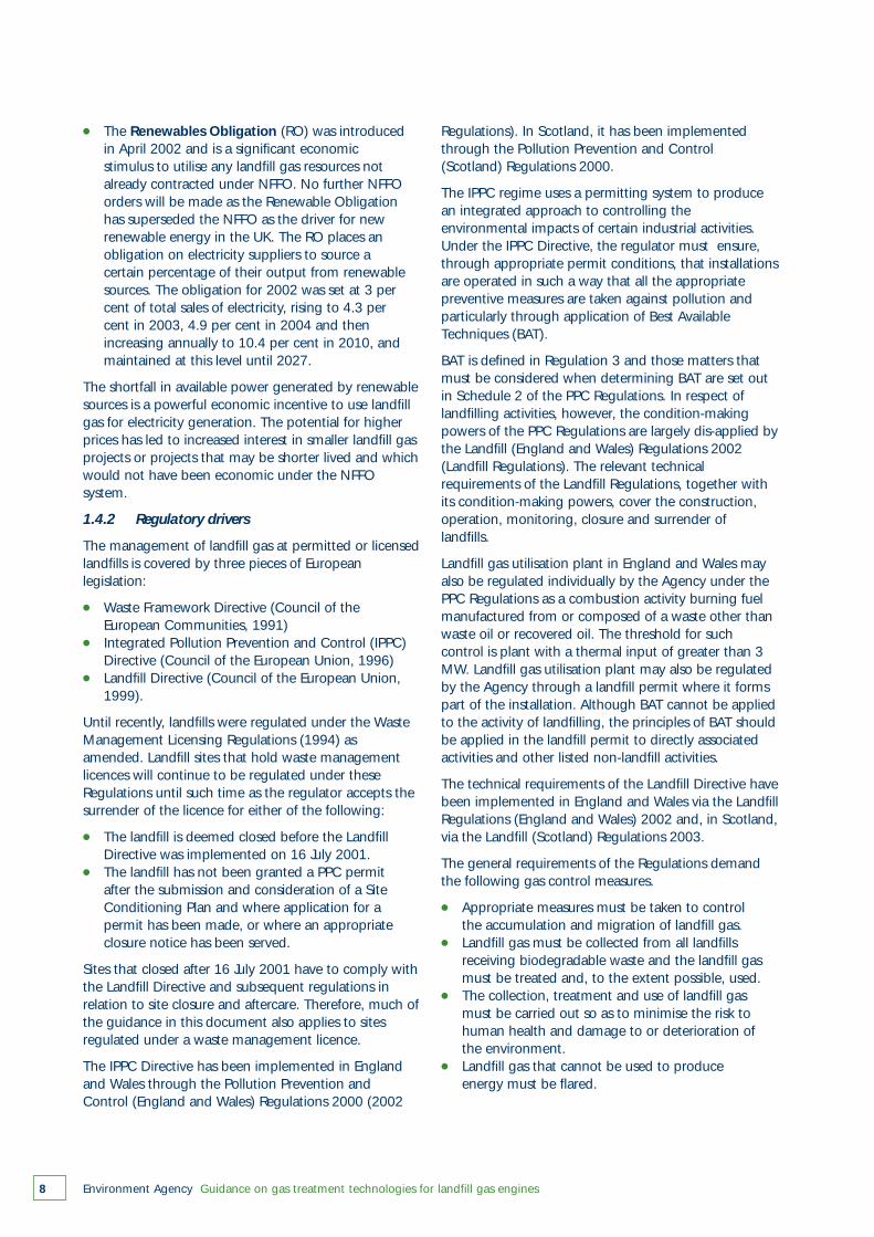
● The Renewables Obligation (RO) was introduced in April 2002 and is a significant economic stimulus to utilise any landfill gas resources not already contracted under NFFO. No further NFFO orders will be made as the Renewable Obligation has superseded the NFFO as the driver for new renewable energy in the UK. The RO places an obligation on electricity suppliers to source a certain percentage of their output from renewable sources. The obligation for 2002 was set at 3 per cent of total sales of electricity, rising to 4.3 per cent in 2003, 4.9 per cent in 2004 and then increasing annually to 10.4 per cent in 2010, and maintained at this level until 2027.
The shortfall in available power generated by renewablesources is a powerful economic incentive to use landfillgas for electricity generation. The potential for higherprices has led to increased interest in smaller landfill gasprojects or projects that may be shorter lived and whichwould not have been economic under the NFFOsystem.
1.4.2 Regulatory drivers
The management of landfill gas at permitted or licensedlandfills is covered by three pieces of Europeanlegislation:
● Waste Framework Directive (Council of the European Communities, 1991)
● Integrated Pollution Prevention and Control (IPPC) Directive (Council of the European Union, 1996)
● Landfill Directive (Council of the European Union, 1999).
Until recently, landfills were regulated under the WasteManagement Licensing Regulations (1994) asamended. Landfill sites that hold waste managementlicences will continue to be regulated under theseRegulations until such time as the regulator accepts thesurrender of the licence for either of the following:
● The landfill is deemed closed before the Landfill Directive was implemented on 16 July 2001.
● The landfill has not been granted a PPC permit after the submission and consideration of a Site Conditioning Plan and where application for a permit has been made, or where an appropriate closure notice has been served.
Sites that closed after 16 July 2001 have to comply withthe Landfill Directive and subsequent regulations inrelation to site closure and aftercare. Therefore, much ofthe guidance in this document also applies to sitesregulated under a waste management licence.
The IPPC Directive has been implemented in Englandand Wales through the Pollution Prevention andControl (England and Wales) Regulations 2000 (2002
Regulations). In Scotland, it has been implementedthrough the Pollution Prevention and Control(Scotland) Regulations 2000.
The IPPC regime uses a permitting system to producean integrated approach to controlling theenvironmental impacts of certain industrial activities.Under the IPPC Directive, the regulator must ensure,through appropriate permit conditions, that installationsare operated in such a way that all the appropriatepreventive measures are taken against pollution andparticularly through application of Best AvailableTechniques (BAT).
BAT is defined in Regulation 3 and those matters thatmust be considered when determining BAT are set outin Schedule 2 of the PPC Regulations. In respect oflandfilling activities, however, the condition-makingpowers of the PPC Regulations are largely dis-applied bythe Landfill (England and Wales) Regulations 2002(Landfill Regulations). The relevant technicalrequirements of the Landfill Regulations, together withits condition-making powers, cover the construction,operation, monitoring, closure and surrender oflandfills.
Landfill gas utilisation plant in England and Wales mayalso be regulated individually by the Agency under thePPC Regulations as a combustion activity burning fuelmanufactured from or composed of a waste other thanwaste oil or recovered oil. The threshold for suchcontrol is plant with a thermal input of greater than 3MW. Landfill gas utilisation plant may also be regulatedby the Agency through a landfill permit where it formspart of the installation. Although BAT cannot be appliedto the activity of landfilling, the principles of BAT shouldbe applied in the landfill permit to directly associatedactivities and other listed non-landfill activities.
The technical requirements of the Landfill Directive havebeen implemented in England and Wales via the LandfillRegulations (England and Wales) 2002 and, in Scotland,via the Landfill (Scotland) Regulations 2003.
The general requirements of the Regulations demandthe following gas control measures.
● Appropriate measures must be taken to control the accumulation and migration of landfill gas.
● Landfill gas must be collected from all landfills receiving biodegradable waste and the landfill gas must be treated and, to the extent possible, used.
● The collection, treatment and use of landfill gas must be carried out so as to minimise the risk to human health and damage to or deterioration of the environment.
● Landfill gas that cannot be used to produce energy must be flared.

Environment Agency Guidance on gas treatment technologies for landfill gas engines 9
It is important to acknowledge the drivers for renewableenergy when considering emission limits and the needfor gas clean-up to meet these limits. Many of the earlyNFFO schemes paid higher prices per unit of electricitysold, but the capital costs were comparatively muchhigher. None of the schemes commissioned to datehave considered gas clean-up when bidding for autilisation contract. This guidance should therefore beused to determine not only whether a technology couldbe of benefit, but also whether it is cost-effective toimplement. Whether the cost-effectiveness constitutesBAT applies only in the case of utilisation plant with aPPC/landfill permit provided under the 2000Regulations.
Gas quality, emission standards andoperational requirements
Environment Agency Guidance on gas treatment technologies for landfill gas engines10
2
2.1 Introduction
The calorific value of landfill gas is predominantlydetermined by the methane/carbon dioxide ratio. Inaddition, landfill gas has been found to contain over500 trace components, which normally constituteonly about 1 per cent by volume. These includehalogenated hydrocarbons, higher alkanes andaromatic hydrocarbons (Environment Agency,2002b). Most higher hydrocarbons will burn but, iftheir calorific value is less than methane, theirpresence will reduce the calorific value of the landfillgas. Some of the aromatics (e.g. benzene) andchlorinated hydrocarbons (e.g. chloroethene) give riseto health concerns, while others are highly odorous(e.g. terpenes, esters and thiols) and some candamage gas utilisation plant (e.g. organohalogens,sulphur species and siloxanes).
The overall trace component composition of landfillgas thus has important health and environmentalimplications and impacts on gas engine performance.The engine manufacturer’s specifications represent agas quality standard at which supply gas clean-upmight need to be considered. Guidance onmonitoring landfill gas engines (Environment Agency,2004a) provides factors for consideration of exhaustgas treatment or in-engine treatment – and, in somecases, supply gas clean-up for some acid gasemissions.
2.2 Engine manufacturers’ specifications
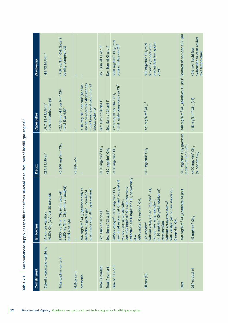
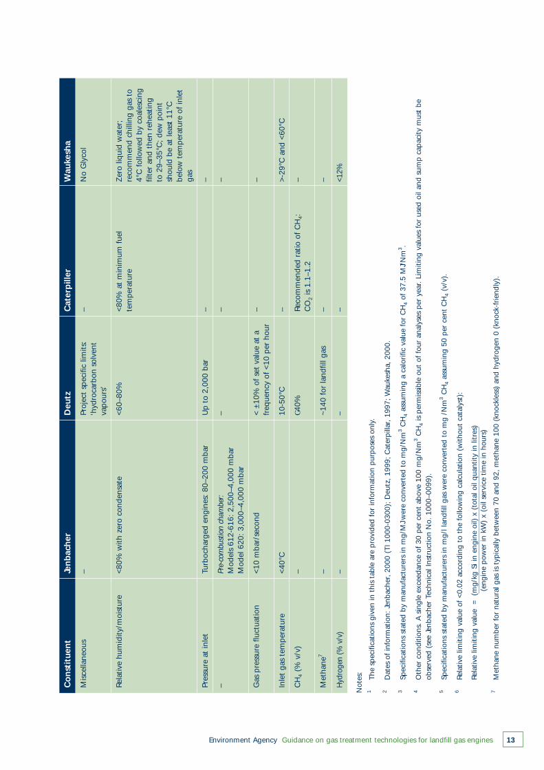
When considering possible treatments for the removalof trace components from landfill gas, it is importantto take into account the requirements placed on thesupply gas by engine manufacturers. Table 2.1provides a summary of recommended gas qualityspecifications from major suppliers of lean burnengines now being used in the EU and USA; theseinclude two US manufacturers (Caterpillar andWaukesha), an Austrian manufacturer (Jenbacher) anda German manufacturer (Deutz).
These gas quality specifications provide a usefulstarting point for site-specific calculations regarding
gas quality and when assessing the need for pre-combustion treatment. Because engine manufacturerslink these specifications to their warranty agreements,it is important that the inlet gas is tested periodicallyusing a method and schedule approved by themanufacturer.
In Table 2.1, the original measurement units providedby the manufacturer have been converted to SI units.The specifications given in Table 2.1 are provided forinformation purposes only. Specifications may varywith engine type, be subject to revision from time totime, and may not reflect specific agreements madebetween the engine manufacturer and engineoperator.
2.2.1 Calorific value
The calorific or heat value of the fuel is determinedpredominantly by the percentage of methanepresent. Typically, this is 35–55 per centvolume/volume (v/v) for landfill gas in the UK.
Pure methane, which has a heat value 9.97 kWe/m3,is the only significant hydrocarbon constituent inlandfill gas converted to mechanical/electrical energyby the engine combustion process. The lower themethane content, the greater the volume of gas thatmust pass through the engine to achieve the samepower output. This in turn means that potentiallymore aggressive gas constituents could enter theengine. This is why manufacturers’ limits foraggressive gas constituents are defined ‘per 100 percent methane’.
Engine air to fuel ratio controllers can adjust this ratioautomatically as the methane content of the supplygas changes, although it may be necessary to modifythe system for significant variations outside theoperating range of 45 ± 15 per cent CH4 v/v.
The calorific value (CV) gives no indication of theaggressiveness of the supply gas or likely emissions.Bulking of supply gas (i.e. supplying the input gas athigher pressure) typically occurs with low calorificvalue gas. The higher inlet pressure of the gas willgenerally result in increased emissions of methane,NMVOCs and other products of incomplete
combustion (PICs). Continuous assessment of flowrate and methane content is necessary to control andminimise this effect (Environment Agency, 2004a).
2.2.2 Sulphur gases
Landfill gas contains a variety of sulphur compounds,several of which are highly odorous. These includesulphides/disulphides (e.g. hydrogen sulphide,dimethyl sulphide, dimethyl disulphide, diethyldisulphide and carbon disulphide) and thiols, e.g.methanethiol (methyl mercaptan), ethanethiol andpropanethiol.
Sulphur compounds are corrosive in the presence offree water or the moisture found within the engine oiland/or landfill gas. These compounds can lead towear on engine piston rings and cylinder linings. Gasrecirculation systems may increase the availability ofmoisture within the engine system. This also affectsoil quality, leading to the need for more frequent oilchanges.
For these reasons, individual engine manufacturersrecommend limits for total sulphur compounds in theinlet landfill gas (see Table 2.1) rather than individualcompounds.
The primary mechanism for the production ofhydrogen sulphide (H2S) in landfills is the reduction ofsulphate under anaerobic conditions by sulphate-reducing micro-organisms. Landfills that are expectedto have higher concentrations of H2S within thelandfill gas include:
● unlined landfills in sulphate-rich geological materials such as gypsum (CaSO4.2H2O) quarries or gypsiferous soils;
● landfills where large quantities of gypsum plasterboard or sulphate-enriched sludges (e.g. from wastewater treatment or flue gas desulphurisation) have been buried;
● landfills where sulphate-rich soils have been used as intermediate cover materials;
● landfills where construction and demolition (C&D)debris containing substantial quantities of gypsumwallboard has been ground down and recycled as daily or intermediate cover.
Typically, landfill gas contains <100 ppm v/v H2S but,at landfills where the sulphate loading is high, valuesfor H2S can be several thousand ppm v/v. Becausecombustion typically destroys 99 per cent of H2S inthe gas engine, treatment for H2S in the supply gas islikely only to need consideration if non-routinemaintenance is regularly required. Emissions of SOx
from combustion of H2S are likely to be below anylocal risk threshold, but local air quality issues must beconsidered on a site-specific basis.
2.2.3 Halogenated compounds
Halogenated compounds containing chlorine,bromine and fluorine (e.g. carbon tetrachloride,chlorobenzene, chloroform and trifluoromethane) arebroken down during the combustion process and canform the acid gases, HCl and HF, in the presence ofmoisture. These are responsible for corrosion of metalpiping and engine components.
Combustion of halogenated compounds in thepresence of hydrocarbons within the landfill gas canalso lead to the subsequent formation of compoundssuch as PCDDs and PCDFs, particularly as thecombusted gases cool below 400°C.
The rate of absorption of chlorine compounds intothe engine oil usually determines the frequency of oilchanges in landfill gas engines. The major enginemanufacturers recommend limits for the inlet landfillgas quality for total chlorine and fluorine content (seeTable 2.1).
Most halogenated species in landfill gas are the resultof direct volatilisation from solid waste components inthe landfill and their presence depends on vapourpressure relationships under landfill conditions. Wastedegradation and landfill gas generation will generatepositive pressures compared with ambient.Temperatures within landfills are also typically aboveambient. The presence of an active landfill gasextraction system will give rise to variations inpressure distribution throughout the waste fill. Inaddition, due to these volatilisation processes, freshwastes generally have a higher content of volatilespecies than older waste.
The most common trace organic components withinlandfill gas mirror the gaseous aromatic andchlorinated compounds produced in the largestquantities by the chemical industry for use inconsumer products. A notable exception ischloroethene (vinyl chloride). This compound andcertain dichlorinated species are thought to beproduced in situ within landfills by anaerobic micro-organisms through reductive dechlorination of higherchlorinated species such as trichloroethylene (TCE)(Molten et al., 1987).
The most common fluorinated species in landfill gasare the chlorofluorocarbons (CFCs), which werewidely used as refrigerants and propellants, and ininsulating foams until their production was greatlyreduced following the recognition of their role instratospheric ozone depletion (Rowland and Molina,1974; World Meteorological Organisation, 1998).CFC-12 (dichlorodifluoromethane) and CFC-11(trichlorofluoromethane) persist at low concentrationsin landfills probably due to their slow volatilisationfrom old waste.
Environment Agency Guidance on gas treatment technologies for landfill gas engines 11
Environment Agency Guidance on gas treatment technologies for landfill gas engines12
Tab
le 2
.1
Reco
mm
ende
d su
pp
ly g
as s
pec
ifica
tions
fro
m s
elec
ted
man
ufac
ture
rs o
f la
ndfil
l gas
eng
ine1,
2
Cal
orifi
c va
lue
and
varia
bilit
yM
axim
um v
aria
tion:
G1
4.4
MJ/
Nm
315
.7–2
3.6
MJ/
Nm
3>1
5.73
MJ/
Nm
3
<0.5
% C
H4
(v/v
) p
er 3
0 se
cond
s(r
ecom
men
ded
rang
e)
Tota
l sul
phu
r co
nten
t2,
000
mg/
Nm
3C
H4
(with
cat
alys
t)<2
,200
mg/
Nm
3C
H4
<2,1
40 m
g H
2S p
er N
m3
CH
4<7
15 m
g/N
m3
CH
4(t
otal
S1,
150
mg/
Nm
3C
H4
(with
out
cata
lyst
)(t
otal
S a
s H
2S)3
bear
ing
com
pou
nds)
(tot
al S
as
H2S
)
H2S
con
tent
–<0
.15%
v/v
––
Am
mon
ia<5
5 m
g/N
m3
CH
4(a
pp
lies
mos
tly t
o–
<105
mg
NH
3p
er N
m3
(ap
plie
s–
anae
robi
c di
gest
er g
as –
com
bine
dm
ainl
y to
ana
erob
ic d
iges
ter
gas
spec
ifica
tions
for
all
biog
as s
yste
ms)
– co
mbi
ned
spec
ifica
tions
for
all
biog
as s
yste
ms)
3
Tota
l Cl c
onte
ntSe
e: S
um o
f C
l and
F<1
00 m
g/N
m3
CH
4Se
e: S
um o
f C
l and
FSe
e: S
um o
f C
l and
F
Tota
l F c
onte
ntSe
e: S
um o
f C
l and
F<5
0 m
g/N
m3
CH
4Se
e: S
um o
f C
l and
FSe
e: S
um o
f C
l and
F
Sum
of
Cl a
nd F
With
out
cata
lyst
4 :<10
0 m
g/N
m3
CH
4<1
00 m
g/N
m3
CH
4<7
13 m
g C
l per
Nm
3C
H4
G300
mg/
Nm
3C
H4
(tot
al(w
eigh
ted
as o
ne p
art
Cl a
nd t
wo
par
ts F
)(t
otal
hal
ide
com
pou
nds
as C
l)3or
gani
c ha
lides
as
Cl)5
with
out
war
rant
y re
stric
tion;
100–
400
mg/
Nm
3C
H4w
ith w
arra
nty
rest
rictio
n; >
400
mg/
Nm
3C
H4
no w
arra
nty
at a
ll W
ith c
atal
yst:
0 m
g/N
m3
CH
4
Silic
on (
Si)
Old
sta
ndar
d<1
0 m
g/N
m3
CH
4<2
1 m
g/N
m3
CH
43
<50
mg/
Nm
3C
H4
tota
lW
ithou
t ca
taly
st3 :
<20
mg/
Nm
3C
H4
silo
xane
s (m
odel
s w
ithw
ithou
t w
arra
nty
rest
rictio
n;p
rech
ambe
r fu
el s
yste
m(>
20
mg/
Nm
3C
H4
with
res
tric
tion)
only
)5
New
sta
ndar
dW
ithou
t ca
taly
st:s
ee b
elow
6
With
cat
alys
t (o
ld o
r ne
w s
tand
ard)
:0
mg/
Nm
3C
H4
Dus
t<5
0 m
g/N
m3
CH
4(p
artic
les
<3 µ
m)
<10
mg/
Nm
3C
H4
(par
ticle
s<3
0 m
g/N
m3
CH
4(p
artic
les
<1 µ
m)3
Rem
oval
of
par
ticle
s >0
.3 µ
mm
axim
um 3
–10
µm)
Oil/
resi
dual
oil
<5 m
g/N
m3
CH
4<4
00 m
g/N
m3
CH
4<4
5 m
g/N
m3
CH
4(o
il)<2
% v
/v ‘l
iqui
d fu
el(o
il va
por
s >C
5)hy
droc
arbo
ns’ a
t at
col
dest
inle
t te
mp
erat
ure
Co
nst
itue
nt
Jen
bac
her
Deu
tzC
ater
pill
erW
auke
sha
Environment Agency Guidance on gas treatment technologies for landfill gas engines 13
Mis
cella
neou
s–
Proj
ect
spec
ific
limits
:–
No
Gly
col
‘hyd
roca
rbon
sol
vent
vap
ours
’
Rela
tive
hum
idity
/moi
stur
e<8
0% w
ith z
ero
cond
ensa
te<6
0–80
%<8
0% a
t m
inim
um f
uel
Zer
o liq
uid
wat
er;
tem
per
atur
ere
com
men
d ch
illin
g ga
s to
4°C
fol
low
ed b
y co
ales
cing
filte
r an
d th
en r
ehea
ting
to 2
9–35
°C;
dew
poi
ntsh
ould
be
at le
ast
11°C
belo
w t
emp
erat
ure
of in
let
gas
Pres
sure
at
inle
tTu
rboc
harg
ed e
ngin
es:
80–2
00 m
bar
Up
to
2,00
0 ba
r–
–
–Pr
e-co
mbu
stio
n ch
ambe
r:–
––
Mod
els
612-
616:
2,5
00–4
,000
mba
rM
odel
620
: 3,
000–
4,00
0 m
bar
Gas
pre
ssur
e flu
ctua
tion
<10
mba
r/se
cond
< ±1
0% o
f se
t va
lue
at a
–
–fr
eque
ncy
of <
10 p
er h
our
Inle
t ga
s te
mp
erat
ure
<40°
C10
-50°
C–
>-29
°C a
nd <
60°C
CH
4(%
v/v
)–
G40%
Reco
mm
ende
d ra
tio o
f C
H4:
–C
O2
is 1
.1–1
.2
Met
hane
7–
~140
for
land
fill g
as–
–
Hyd
roge
n (%
v/v
)–
––
<12%
Co
nst
itue
nt
Jen
bac
her
Deu
tzC
ater
pill
erW
auke
sha
Not
es:
1Th
e sp
ecifi
catio
ns g
iven
in t
his
tabl
e ar
e p
rovi
ded
for
info
rmat
ion
pur
pos
es o
nly.
2D
ates
of
info
rmat
ion:
Jenb
ache
r, 20
00 (
TI 1
000-
0300
); D
eutz
, 19
99;
Cat
erp
illar
, 19
97;
Wau
kesh
a, 2
000.
3Sp
ecifi
catio
ns s
tate
d by
man
ufac
ture
rs in
mg/
MJ w
ere
conv
erte
d to
mg/
Nm
3C
H4
assu
min
g a
calo
rific
val
ue f
or C
H4
of 3
7.5
MJ/
Nm
3 .
4O
ther
con
ditio
ns.
A s
ingl
e ex
ceed
ance
of
30 p
er c
ent
abov
e 10
0 m
g/N
m3
CH
4is
per
mis
sibl
e ou
t of
fou
r an
alys
es p
er y
ear.
Lim
iting
val
ues
for
used
oil
and
sum
p c
apac
ity m
ust
be
obse
rved
(se
e Je
nbac
her
Tech
nica
l Ins
truc
tion
No.
100
0–00
99).
5Sp
ecifi
catio
ns s
tate
d by
man
ufac
ture
rs in
mg/
l lan
dfill
gas
wer
e co
nver
ted
to m
g /N
m3
CH
4as
sum
ing
50 p
er c
ent
CH
4(v
/v).
6Re
lativ
e lim
iting
val
ue o
f <0
.02
acco
rdin
g to
the
fol
low
ing
calc
ulat
ion
(with
out
cata
lyst
):
Rela
tive
limiti
ng v
alue
=
(m
g/kg
Si i
n en
gine
oil)
x (
tota
l oil
qua
ntity
in li
tres
) (e
ngin
e p
ower
in k
W)
x (o
il se
rvic
e tim
e in
hou
rs)
7M
etha
ne n
umbe
r fo
r na
tura
l gas
is t
ypic
ally
bet
wee
n 70
and
92,
met
hane
100
(kn
ockl
ess)
and
hyd
roge
n 0
(kno
ck-f
riend
ly).
Environment Agency Guidance on gas treatment technologies for landfill gas engines14
In general, landfill gas quality appears to beimproving with the withdrawal of certain substancessuch as hydrochlorofluorocarbons (HCFCs) fromwidespread use. Sites that accept wastes with highchlorine and fluorine concentrations are likely toproduce landfill gas – and similarly exhaust emissions– where HCl, HF and PCDDs/PCDFs may be abovethe norm.
While a third of UK landfills have aggressive gascharacteristics requiring high Total Base Number(TBN) lubricating oils, only a small percentage of theexhaust emissions with HCl and HF may requiretreatment. These emissions might need to beaddressed at landfills where industrial waste has beenaccepted and where concentrations in the exhaustare shown to be potentially harmful as determined bya site-specific risk assessment/emission standard.
2.2.4 Ammonia
Ammonia is a problem for digester gas engines andmanufacturers set strict limits for it for enginesburning digester gas. It is found occasionally inlandfill gas and manufacturers may apply similar limitsto landfill gas engines. The combustion of ammonialeads to the formation of nitric oxide (NO), which canreact to form other oxides of nitrogen in theatmosphere.
2.2.5 Silicon compounds and siloxanes
Silicon, silicon dioxide and siloxanes all behave indifferent ways. An identical landfill gas engine used attwo different sites with a high silicon content canresult in widely varying effects, making ‘trial anderror’ solutions the current norm.
Discarded consumer products (including cosmetics) inthe landfill tend to be the main source of silicon inthe supply gas. Many consumer products (hair care,skin care, underarm deodorants) and commerciallubricants contain silicones (a large group of relatedorganosilicon polymers).
The term siloxane refers to a subgroup of siliconescontaining Si-O bonds with organic radicals bondedto the silicon atom; the organic radicals can includemethyl, ethyl and other organic functional groups.Siloxanes are present in landfills through:
● the disposal of containers with small amounts of remaining silicon-containing product
● the landfilling of wastewater treatment sludges (siloxanes are retained during the process steps).
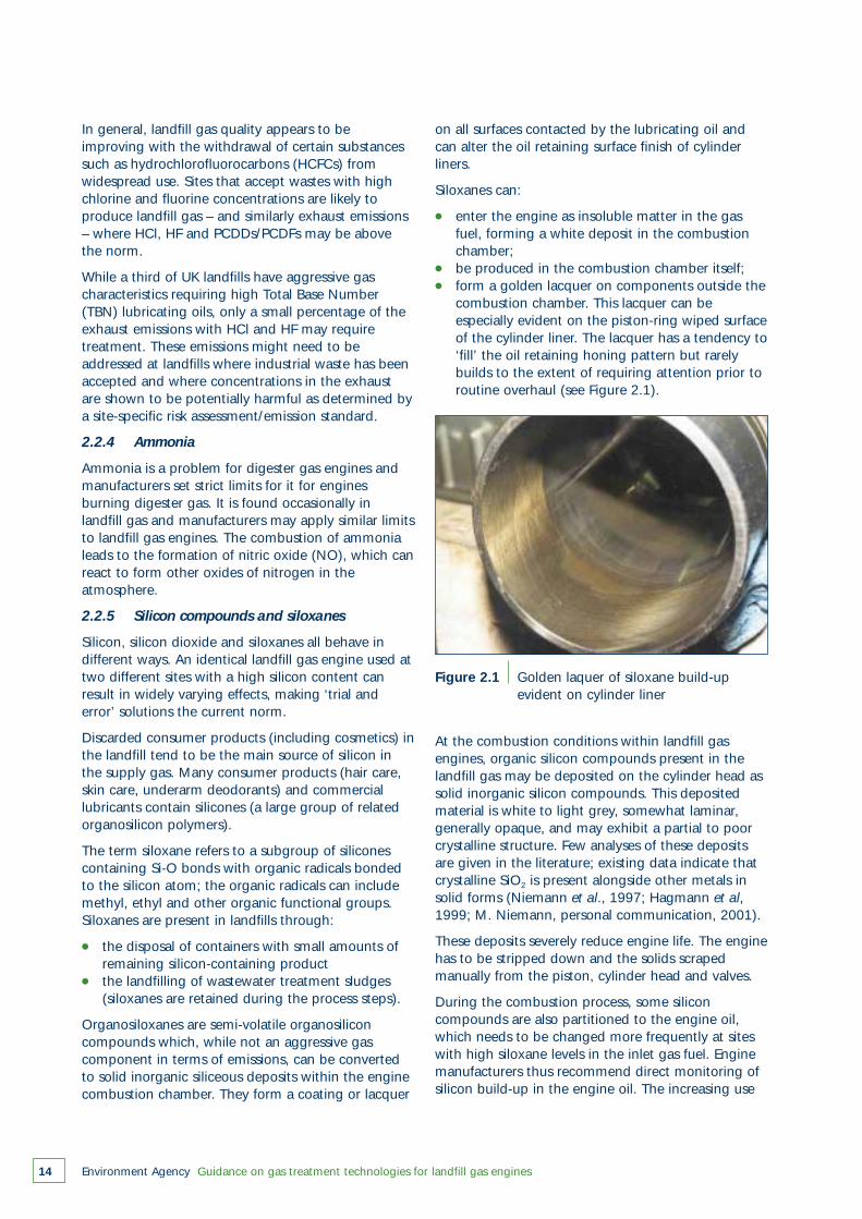
Organosiloxanes are semi-volatile organosiliconcompounds which, while not an aggressive gascomponent in terms of emissions, can be convertedto solid inorganic siliceous deposits within the enginecombustion chamber. They form a coating or lacquer
Figure 2.1 Golden laquer of siloxane build-up evident on cylinder liner
At the combustion conditions within landfill gasengines, organic silicon compounds present in thelandfill gas may be deposited on the cylinder head assolid inorganic silicon compounds. This depositedmaterial is white to light grey, somewhat laminar,generally opaque, and may exhibit a partial to poorcrystalline structure. Few analyses of these depositsare given in the literature; existing data indicate thatcrystalline SiO2 is present alongside other metals insolid forms (Niemann et al., 1997; Hagmann et al,1999; M. Niemann, personal communication, 2001).
These deposits severely reduce engine life. The enginehas to be stripped down and the solids scrapedmanually from the piston, cylinder head and valves.
During the combustion process, some siliconcompounds are also partitioned to the engine oil,which needs to be changed more frequently at siteswith high siloxane levels in the inlet gas fuel. Enginemanufacturers thus recommend direct monitoring ofsilicon build-up in the engine oil. The increasing use
on all surfaces contacted by the lubricating oil andcan alter the oil retaining surface finish of cylinderliners.
Siloxanes can:
● enter the engine as insoluble matter in the gas fuel, forming a white deposit in the combustion chamber;
● be produced in the combustion chamber itself;● form a golden lacquer on components outside the
combustion chamber. This lacquer can be especially evident on the piston-ring wiped surfaceof the cylinder liner. The lacquer has a tendency to‘fill’ the oil retaining honing pattern but rarely builds to the extent of requiring attention prior to routine overhaul (see Figure 2.1).
of these compounds in consumer and commercialproducts suggests that problems with volatilesiloxanes in landfill gas engines are likely to increase.
There is currently no standard method for analysingvolatile siloxanes in a gaseous matrix; at least ten ormore methods are being used (e.g. Aramata andSaitoh, 1997; Grumping et al., 1998; Hone and Fry,1994; Huppman et al., 1996; Kala et al., 1997;Schweigkofler and Niessner, 1999; Stoddart et al.,1999; Varaprath and Lehmann, 1997; Wachholz et al.,1995). There is no consensus within the landfill gasindustry regarding which method to use and therehas been no rigorous comparison of methods using acommon set of samples.
Observations of individual well samples andcomposite landfill gas samples vary between <1 and>100 ppm v/v total organic silicon, based on a gaschromatography/atomic emission detection method(GC/AED). For some applications and especially theevaluation of potential treatment methods,determination of speciated siloxanes may be desirableusing a combined GC/AED-MS (mass spectrometry)method (e.g. Schweigkofler and Niessner, 1999).
Siloxanes do not directly cause problems with gasengine exhaust emissions, though the increased wearmay show itself as an increase in SOx emissions aslubricating oil is burnt. Typically, this is unlikely toexceed any risk-based criterion for emissionsmanagement and the decision to implement gasclean-up for siloxane management purposes isentirely based on cost.
2.2.6 Dust
Dust can be drawn into engines either in the landfillgas itself or in the combustion air. Particulate filtersand cyclones (see Section 4), which are relativelycommon, remove liquid droplets and particulates(above a limiting threshold size) from the supply gas.However, due to the dusty external environment,attention should also be paid to the combustion airdrawn into the engine container or building andespecially to the air drawn into the engine.
Two stages of inlet air filtration are therefore involved.They are located:
● on the engine enclosure inlet. The filtration level isthat necessary to prevent an unacceptable, visual build-up of dust on engine and ancillary plant.
● at the engine inlet. This filtration is particularly important as abrasive silica is a major culprit of premature component wear (down to 5 mm on the cell inlet filter and down to 2 mm on the secondary engine mounted filtration).
Environment Agency Guidance on gas treatment technologies for landfill gas engines 15
Cyclone or oil-wetted filters can be used if thelocation has ‘desert-like’ conditions or if dustyindustrial processes such as cement production arelocated near the generating plant.
All utilisation plant should have dust filtrationequipment installed if particulates in the supply gasare identified as a particular problem. Furtherinformation is given in Section 4.
2.2.7 Lubricating oil
The combustion of landfill gas containing siloxanesand organohalogen compounds introduces acids intothe lubricating oil of the engine. It is known from thevolume of high total base number (TBN) oilformulations used on landfill gas engines thatapproximately one third of UK landfill gas generatorssuffer from aggressive concentrations oforganohalogens (Hussein Younis, Exxon Mobil,personal communication, 2002).
The acid forming chloride, fluoride and sulphurcompounds contaminate the lubricating oil mostly bybypassing the piston rings (blow-by) and, to a lesserextent, via the air and exhaust valve guides. Keepingthe engine operating temperatures of jacket coolingwater and associated lubricating oil temperatureshigh (to avoid dew points) may reduce the effect ofthese acids. However, a higher oil temperature doesreduce the thickness of the crankshaft oil film and anoptimum balance must be achieved.
Corrosion is prevented by keeping the oil alkaline andby using corrosion resistant components (especially atthe crankshaft, camshaft and other bearings).Aluminium-tin may be used to replace ‘yellow metal’bearings such as copper or phosphor bronze.
Lubricating oil additives are used to maintainalkalinity; these additives must be non-combustibleand thus produce more ash. Some ash serves as alubricant for valve seats. However, if there is toomuch ash, maintenance intervals decrease and in-cylinder temperature sensors become less effectivedue to premature detonation owing to a build-up ofdeposits.
A balance has therefore to be achieved between ahigh alkalinity (high TBN) oil and the frequency of oilreplacement. Longer periods between oil changesmay be achieved with larger engine sump capacities.An engine approaching the need for overhaul willallow greater absorption owing to increased blow-by.Oil replacement frequencies are typically 750–850hours. Shutting down engines to undertake oilreplacement usually coincides with spark plugreplacement.
Environment Agency Guidance on gas treatment technologies for landfill gas engines16
2.3 Destruction efficiencies of gas engines
The environment can benefit from the destruction ofsome components of landfill gas in the combustionchamber of an engine – particularly if the alternativeis uncontrolled surface emissions of thesecomponents. However, the short residence time inthe gas engine means that no trace gas componentcan be destroyed with 100 per cent efficiency.Furthermore, other components such as HCl, HF andSOx will be produced as a result of the combustion ofchlorine-, fluorine- and sulphur-containingcompounds in the landfill gas.
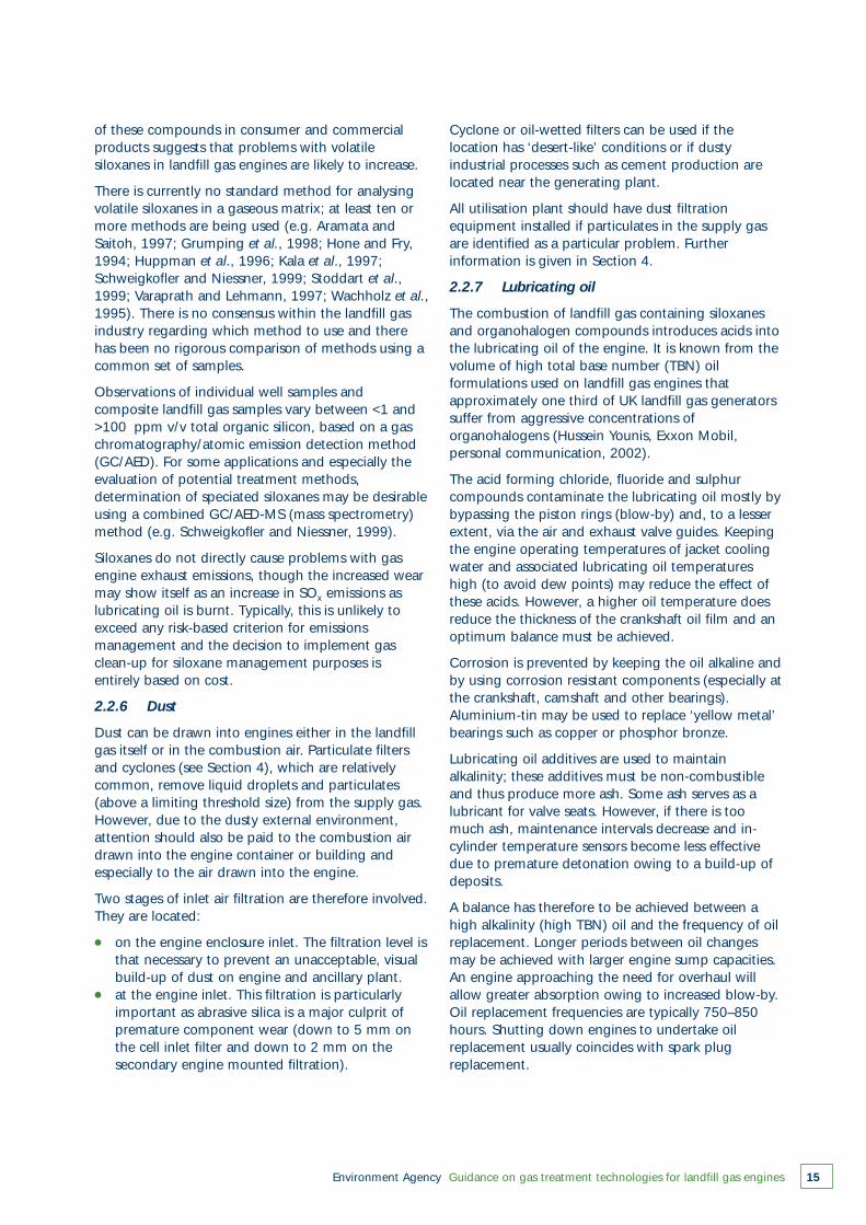
Table 2.2 gives typical destruction efficiencies ofvarious types of organic compounds; these valueswere obtained by monitoring a number of landfill gasengines in he UK (Gillett et al., 2002). The limit ofdetection of these compounds in the engine exhaustmeans that some of the minima are only estimatesand that the actual destruction efficiency will bemuch higher than that the minimum given in Table 2.2.
The destruction of methane to form carbon dioxide istypically 96–99.6 per cent. Longer chain alkanes arenormally destroyed at between 92 and >99.9 percent efficiency, but Gillett et al. (2002) reported thatbutane was destroyed by only 70 per cent and thatsome lighter alkanes appeared to be formed.
The unburnt methane and other hydrocarbonsleaving the exhaust represent a relatively smallfraction of the fuel, and the amount of methane‘slippage’ is a feature of engine design. Somemethane escapes from the combustion chamberbefore it is ‘closed’, while some methane remains
after combustion and is discharged on the non-combustion stroke.
In general, Gillet et al. (2002) also observed highdestruction efficiencies (up to 99.9 per cent) forsimple substituted alkanes such as alcohols, aldehydesand ketones, but there were some exceptions. Thecombustion chamber and exhaust system of a gasengine is a highly reactive chemical environment andsome simple compounds may be formedpreferentially from the destruction of other complexorganic species.
Aromatic compounds are destroyed at between 92and 99.9 per cent efficiency. Terpenes, which areresponsible for some odour events on landfills, aredestroyed at >99.9 per cent efficiency. Sulphurcompounds, which are responsible for most odourcomplaints, are destroyed at between 8.7 and 96.6per cent efficiency. Hydrogen sulphide, the mostcommon sulphur compound, has been found toundergo 70.6–96.6 per cent destruction in a gasengine (this observation contradicts claims that thegas is flammable and thus will be completelydestroyed).
The destruction efficiency for halogenatedcompounds – potentially some of the most toxiccompounds in landfill gas – is between 70 and 99.7per cent. However, research suggests that someanomalous calculated destruction efficiencies are aresult of very small amounts of these compoundsbeing present.
The observed values shown in Table 2.2 indicate thatgas engines are capable of destroying tracecomponents to high degrees of efficiency. These
Table 2.2 Typical destruction efficiencies for various types of organic compound*
Methane 96.0 99.6
Alkanes 70.2 >99.9
Alkenes 50.1 >99.6
Alcohols 84.1 >99.8
Aldehydes >42.4 95.9
Ketones >87.4 99.9
Aromatic hydrocarbons 92.0 >99.9
Terpenes – >99.9
Sulphur compounds >8.7 >96.6
Halogenated hydrocarbons >70.1 >99.7
Type of compound Minimum (%) Maximum (%)
* Based on Gillett et al. (2002)
Environment Agency Guidance on gas treatment technologies for landfill gas engines 17
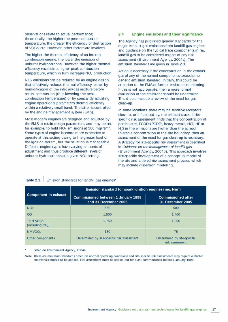
Table 2.3 Emission standards for landfill gas engines*
NOx 650 500
CO 1,500 1,400
Total VOCs 1,750 1,000(including CH4)
NMVOCs 150 75
Other components Determined by site-specific risk assessment Determined by site-specificrisk assessment
Component in exhaustEmission standard for spark ignition engines (mg/Nm3)
Commissioned between 1 January 1998 Commissioned after and 31 December 2005 31 December 2005
* Based on Environment Agency, 2004a.
Note: These are minimum standards based on normal operating conditions and site-specific risk assessments may require a stricteremissions standard to be applied. Risk assessment must be carried out for plant commissioned before 1 January 1998.
observations relate to actual performance;theoretically, the higher the peak combustiontemperature, the greater the efficiency of destructionof VOCs, etc. However, other factors are involved.
The higher the thermal efficiency of an internalcombustion engine, the lower the emission ofunburnt hydrocarbons. However, the higher thermalefficiency results in a higher peak combustiontemperature, which in turn increases NOx production.
NOx emissions can be reduced by an engine designthat effectively reduces thermal efficiency, either byhumidification of the inlet air/gas mixture beforeactual combustion (thus lowering the peakcombustion temperature) or by constantly adjustingengine operational parameters/thermal efficiencywithin a relatively small band. The latter is controlledby the engine management system (EMS).
Most modern engines are designed and adjusted bythe EMS to retain design parameters, and may be set,for example, to hold NOx emissions at 500 mg/Nm3.Some types of engine become more expensive tooperate at this setting owing to the greater load onthe ignition system, but the situation is manageable.Different engine types have varying amounts ofadjustment and thus produce different levels ofunburnt hydrocarbons at a given NOx setting.
2.4 Engine emissions and their significance
The Agency has published generic standards for themajor exhaust gas emissions from landfill gas enginesand guidance on the typical trace components in rawlandfill gas to be considered as part of any riskassessment (Environment Agency, 2004a). Theemission standards are given in Table 2.3.
Action is necessary if the concentration in the exhaustgas of any of the named components exceeds thegeneric emission standard. Initially, this could beattention to the EMS or further emissions monitoring.If this is not appropriate, then a more formalevaluation of the emissions should be undertaken.This should include a review of the need for gasclean-up.
In some locations, there may be sensitive receptorsclose to, or influenced by, the exhaust stack. If site-specific risk assessment finds that the concentration ofparticulates, PCDDs/PCDFs, heavy metals, HCl, HF orH2S in the emissions are higher than the agreedtolerable concentration at the site boundary, then anassessment of the need for gas clean-up is necessary.A strategy for site-specific risk assessment is describedin Guidance on the management of landfill gas(Environment Agency, 2004b). This approach involvessite-specific development of a conceptual model ofthe site and a tiered risk assessment process, whichmay include dispersion modelling.

Environment Agency Guidance on gas treatment technologies for landfill gas engines18
Development of the conceptual site model involves:
● defining the nature of the landfill, the gas utilisation plant and the baseline environmental conditions;
● identifying the source term releases, the pathways and receptors for the plant emissions, and the processes likely to occur along each of the source–pathway–receptor linkages. In the case of engines, the most likely pathway is atmospheric dispersion of the exhaust plume.
At the hazard identification and risk screening stage,the sensitivity of the receptors should be consideredand an initial selection of the appropriateenvironmental benchmark for each receptor shouldbe made. Suitable benchmarks include EnvironmentalAssessment Levels (EALs) or air quality objectives).Long-term and short-term EALs are given inHorizontal Guidance Note H1 (Environment Agency,2002a).
An atmospheric dispersion model of the fate of theexhaust plume is likely to form part of the PPCapplication; this information will also be useful in therisk assessment. The procedures that should befollowed in the cost benefit analysis of the need forgas clean-up are given in Section 3.
2.5 Crankcase emissions
The engine exhaust is not the only source ofatmospheric emissions from gas engines. Combustionproducts that pass the piston rings (blow-by) and, toa lesser extent, escape past valve guide clearances,cause a positive pressure in the engine crankcase andcontaminate the lubricating oil.
Historically, a crankcase vacuum of around 1 inchwater gauge was used to counter this pressure andminimise lubricating oil leaks. However, extraction ofthe crankcase emissions reduces the rate ofcontamination of the lubricating oil – producing adirect saving in oil costs.
Exhaust from the extractor fan takes the form of alow volume and flow rate smoke. This exhaust – orthe crankcase fumes – is often passed through alength of pipework to promote condensation of theoil; the remaining vapour is then passed through acoalescer/filter. Simply exhausting the fumes belowwater is another method that has been employed.Increasing the volume of flow to positively purge thecrankcase could be considered a form of in-engineclean-up.
Gillett et al. (2002) found that untreated crankcaseexhaust had high concentrations of aggressive gases,but at very low mass flow. This volume can be up to
30 per cent of the total mass emission rates ofunburnt hydrocarbons and SOx from the engine, andtreatment is considered best practice. The directrelease of crankcase exhaust emissions is generally nolonger acceptable and any crankcase emissions needto be included in any PPC reporting requirements.
Options for management of this emission source are:
● Recirculation of the crankcase fumes into the combustion chamber inlet – this affects component life, but the emissions are combined and diluted in the exhaust.
● Recirculation by injection after combustion – this increases the life of engine components, while the emissions are combined and diluted in the exhaust.
● Installation of coalescer and filter – this increases component life but produces an additional, low volume waste stream.
The cheapest option is to recirculate and most enginemanufacturers (Deutz, Jenbacher and Caterpillar)have adopted it. A coalescer and filter could be fittedat a cost of £1,500–£3,000 (depending on flow rateand degree of reduction). If the supply gas is highlyacidic, then there will be to additional cost ofdisposing of the waste stream.
Environment Agency Guidance on gas treatment technologies for landfill gas engines 19
Decision process: assessing the use ofclean-up technologies
3
3.1 Clean-up approaches
Raw landfill gas is a complex and variable mixture ofgases and vapours. Active management of such amixture will be affected by the trace components andcontaminants. The role of pre-combustion gas clean-up is to reduce the effects of the contaminants on thehandling plant and to promote a high degree ofoperational effectiveness. This, in turn, may improvethe management of secondary waste streams,including emissions to atmosphere. Enginemanagement systems and post-combustion activitiescan also be used to manage emissions to atmosphere.
Clean-up options range from commonly adoptedsimple water trapping and filtration to complexintegrated systems linked to the energy utilisationplant or landfill gas abstraction plant.
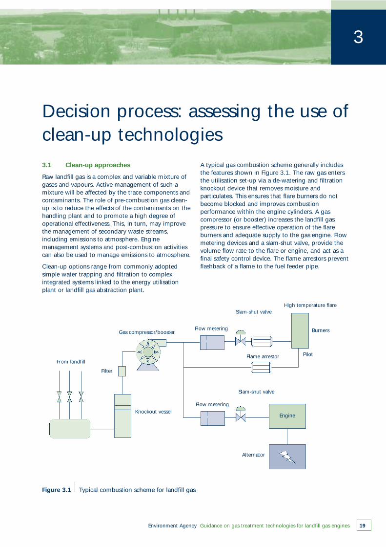
A typical gas combustion scheme generally includesthe features shown in Figure 3.1. The raw gas entersthe utilisation set-up via a de-watering and filtrationknockout device that removes moisture andparticulates. This ensures that flare burners do notbecome blocked and improves combustionperformance within the engine cylinders. A gascompressor (or booster) increases the landfill gaspressure to ensure effective operation of the flareburners and adequate supply to the gas engine. Flowmetering devices and a slam-shut valve, provide thevolume flow rate to the flare or engine, and act as afinal safety control device. The flame arrestors preventflashback of a flame to the fuel feeder pipe.
Figure 3.1 Typical combustion scheme for landfill gas
From landfill
Filter
Knockout vessel
Gas compressor/booster
Flow metering
Flow metering
Slam-shut valve
Slam-shut valve
Flame arrestor
Engine
Alternator
High temperature flare
Burners
Pilot
Environment Agency Guidance on gas treatment technologies for landfill gas engines20
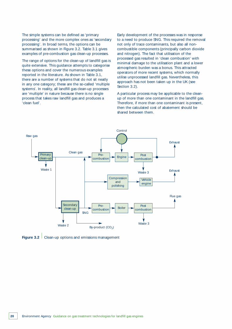
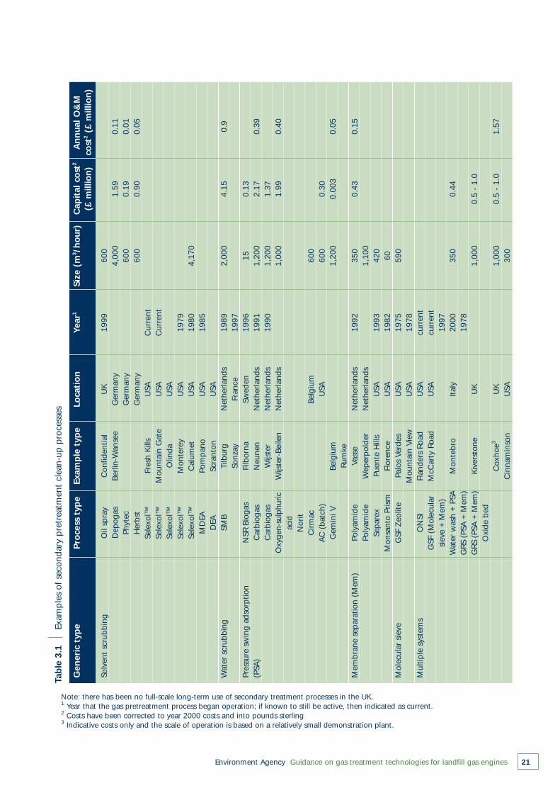
The simple systems can be defined as ‘primaryprocessing’ and the more complex ones as ‘secondaryprocessing’. In broad terms, the options can besummarised as shown in Figure 3.2. Table 3.1 givesexamples of pre-combustion gas clean-up processes.
The range of options for the clean-up of landfill gas isquite extensive. This guidance attempts to categorisethese options and cover the numerous examplesreported in the literature. As shown in Table 3.1,there are a number of systems that do not sit neatlyin any one category; these are the so-called ‘multiplesystems’. In reality, all landfill gas clean-up processesare ‘multiple’ in nature because there is no singleprocess that takes raw landfill gas and produces a‘clean fuel’.
Figure 3.2 Clean-up options and emissions management
Early development of the processes was in responseto a need to produce SNG. This required the removalnot only of trace contaminants, but also all non-combustible components (principally carbon dioxideand nitrogen). The fact that utilisation of theprocessed gas resulted in ‘clean combustion’ withminimal damage to the utilisation plant and a loweratmospheric burden was a bonus. This attractedoperators of more recent systems, which normallyutilise unprocessed landfill gas. Nevertheless, thisapproach has not been taken up in the UK (seeSection 3.2).
A particular process may be applicable to the clean-up of more than one contaminant in the landfill gas.Therefore, if more than one contaminant is present,then the calculated cost of abatement should beshared between them.
Raw gas
Primaryclean-up
Pre-combustion Boiler
Postcombustion
Vehicleengine
Clean gas
Control
Exhaust
Exhaust
Flue gas
Waste 3
Waste 3
By-product (CO2)Waste 2
Waste 1
SNG
Compressionand
polishing
Pre-combustion Engine
Postcombustion
Secondaryclean-up
Environment Agency Guidance on gas treatment technologies for landfill gas engines 21
Tab
le 3
.1
Exam
ple
s of
sec
onda
ry p
retr
eatm
ent
clea
n-up
pro
cess
es
Solv
ent
scru
bbin
gO
il sp
ray
Con
fiden
tial
UK
1999
600
Dep
ogas
Berli
n-W
anse
eG
erm
any
4,00
01.
590.
11Ph
ytec
Ger
man
y60
00.
190.
01H
erbs
tG
erm
any
600
0.90
0.05
Sele
xol™
Fres
h Ki
llsU
SAC
urre
ntSe
lexo
l™M
ount
ain
Gat
eU
SAC
urre
ntSe
lexo
l™O
linda
USA
Sele
xol™
Mon
tere
yU
SA19
79Se
lexo
l™C
alum
etU
SA19
804,
170
MD
EAPo
mp
ano
USA
1985
DEA
Sc
rant
onU
SAW
ater
scr
ubbi
ngSM
BTi
lbur
gN
ethe
rland
s19
892,
000
4.15
0.9
Sonz
ayFr
ance
1997
Pres
sure
sw
ing
adso
rptio
nN
SR B
ioga
sFi
lbor
naSw
eden
1996
150.
13(P
SA)
Car
biog
asN
eune
nN
ethe
rland
s19
911,
200
2.17
0.39
Car
biog
asW
ijste
rN
ethe
rland
s19
901,
200
1.37
Oxy
gen-
sulp
huric
Wijs
ter-
Beile
nN
ethe
rland
s1,
000
1.99
0.40
acid
Nor
itC
irmac
Belg
ium
600
AC
(ba
tch)
USA
600
0.30
Gem
ini V
Belg
ium
1,20
00.
003
0.05
Rum
keM
embr
ane
sep
arat
ion
(Mem
)Po
lyam
ide
Vass
eN
ethe
rland
s19
9235
00.
430.
15Po
lyam
ide
Wep
erp
olde
rN
ethe
rland
s1,
100
Sep
arex
Puen
te H
ills
USA
1993
420
Mon
sant
o Pr
ism
Flor
ence
USA
1982
60M
olec
ular
sie
veG
SF Z
eolit
ePa
los
Verd
esU
SA19
7559
0M
ount
ain
View
USA
1978
Mul
tiple
sys
tem
sO
NSI
Flan
ders
Roa
dU
SAcu
rren
tG
SF (
Mol
ecul
arM
cCar
ty R
oad
USA
curr
ent
siev
e +
Mem
)19
97W
ater
was
h +
PSA
Mon
tebr
oIt
aly
2000
350
0.44
GRS
(PS
A +
Mem
)19
78G
RS (
PSA
+ M
em)
Kive
rsto
neU
K1,
000
0.5
- 1.
0O
xide
bed
Cox
hoe3
UK
1,00
00.
5 -
1.0
1.57
Cin
nam
inso
nU
SA30
0
Gen
eric
typ
ePr
oce
ss t
ype
Exam
ple
typ
eLo
cati
on
Year
1Si
ze (
m3 /h
our
)C
apit
al c
ost
2A
nn
ual O
&M
(£ m
illio
n)
cost
2(£
mill
ion
)
Note: there has been no full-scale long-term use of secondary treatment processes in the UK.1 Year that the gas pretreatment process began operation; if known to still be active, then indicated as current.2 Costs have been corrected to year 2000 costs and into pounds sterling 3 Indicative costs only and the scale of operation is based on a relatively small demonstration plant.
Environment Agency Guidance on gas treatment technologies for landfill gas engines22
3.2 Potential for substitute natural gas as a fuel for landfill gas engines
The current global gas market is such that SNGproduced from landfill gas is likely to be financiallymarginal at best; this is confirmed by the case studiesconsidered in recent Agency research (EnvironmentAgency, 2004d). Developing plant to exploit thismarket in the UK is thus unlikely to satisfy investmentcriteria.
However, various other options for clean-up processesmay be worth developing to enhance the operationof existing and future systems for utilising ‘raw landfillgas’. The focus of such development will be theremoval of trace contaminants (especiallyhalogenated organics and siloxanes) withoutnecessarily having to remove the non-combustiblebulk gases. Nevertheless, the economics of the clean-up options are currently far from clear, but athorough review could show that minimising the totalmass flow prior to clean-up (i.e. first using a low-costprocess to remove non-combustibles – essentiallycarbon dioxide) might offer significant operationaland financial advantages.
Carbon dioxide removal processes effectively‘upgrade’ the calorific value of the gas. Suchprocesses fall into four basic categories:
● absorption by a liquid (solvent)● adsorption by a granular solid● differential transport (membrane separation)● cryogenic separation.
The underlying principles defining these categoriesare described in Section 5. However, the futureapplicability of landfill gas clean-up suggests that themost appropriate – and, by implication, the lowestcost – option is likely to be liquid absorption usingwater as the solvent. However, further evaluation andfinancial analysis may show otherwise, and at thisstage, no options should be ruled out.
When producing SNG, the principal requirement ofgas clean-up technology is to remove (or minimise)the concentrations of reactive trace components. Thiscan be partly achieved during ‘upgrading’ to removecarbon dioxide; but to be fully effective, it requiresadditional processing stages. These stages are likely tobe sorption processes that target either individual orgroups of reactive contaminants. The optionsshowing the greatest promise are activated carbonand proprietary compounds based on activatedcarbon. However, solvent absorption offers theadvantage of continuous processing and thus shouldnot be rejected until a more detailed analysis hasbeen undertaken.
3.3 The framework for assessing gas clean-up
The basis for this approach is explained in HorizontalGuidance H1 (Environment Agency, 2002a). Rigorouscost benefit analysis of the various gas clean-upoptions has not been carried out in this guidance dueto:
● a lack of adequate cost and performance data for comparable systems;
● available information on multiple systems is focussed on SNG as the product and not on landfill gas engine use;
● a reticence within the industry to discuss the costsof implementation of any technology unless a real situation is involved.
However, the mechanism for conducting a rigorousCBA is described for situations when these databecome available for a site-specific requirement.
The aim of Horizontal Guidance Note H1 is to:
● provide information on the preferred methods for quantifying environmental impacts to all media (air, water and land)
● calculate costs● provide guidelines on how to resolve any cross-
media conflicts.
The methods outlined in Horizontal Guidance NoteH1 can be used to conduct a costs/benefits appraisalof options to determine best practice or BAT forselected releases from any installation. Spreadsheetsare provided in help users evaluate the options orassess the overall environmental impact of emissions.In order to gain a PPC permit, operators have toshow that their proposals represent best practice orBAT to prevent and minimise pollution from theirinstallation.
The following six steps in the assessmentmethodology apply and are described in more detailin Section 3.5.
1 Define the objective of the assessment and the options to be considered.
2 Quantify the emissions from each option.3 Quantify the environmental impacts resulting from
the different options.4 Compare options and rank in order of best overall
environmental performance.5 Evaluate the costs to implement each option.6 Identify the option that represents the most cost-
effective technique or BAT by balancing environmental benefits against costs.
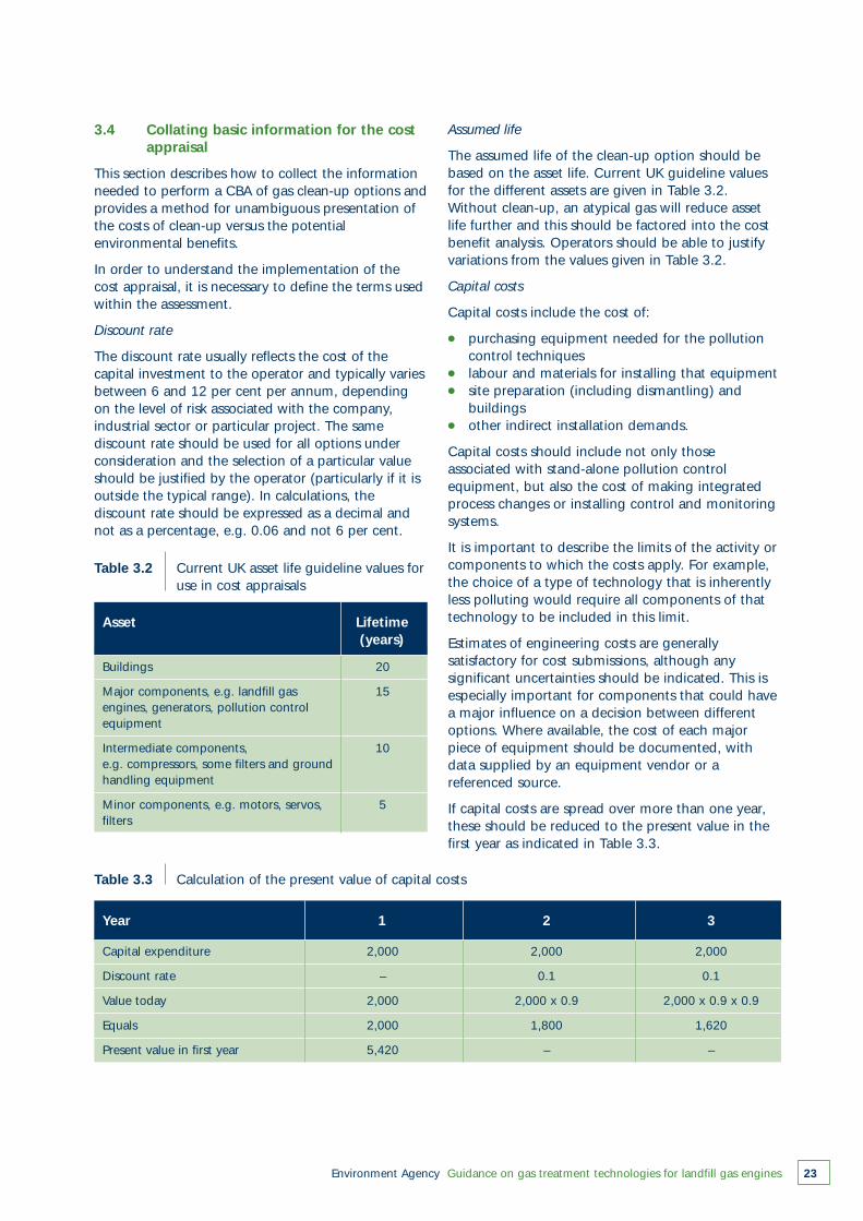
Environment Agency Guidance on gas treatment technologies for landfill gas engines 23
3.4 Collating basic information for the cost appraisal
This section describes how to collect the informationneeded to perform a CBA of gas clean-up options andprovides a method for unambiguous presentation ofthe costs of clean-up versus the potentialenvironmental benefits.
In order to understand the implementation of thecost appraisal, it is necessary to define the terms usedwithin the assessment.
Discount rate
The discount rate usually reflects the cost of thecapital investment to the operator and typically variesbetween 6 and 12 per cent per annum, dependingon the level of risk associated with the company,industrial sector or particular project. The samediscount rate should be used for all options underconsideration and the selection of a particular valueshould be justified by the operator (particularly if it isoutside the typical range). In calculations, thediscount rate should be expressed as a decimal andnot as a percentage, e.g. 0.06 and not 6 per cent.
Table 3.2 Current UK asset life guideline values for use in cost appraisals
Buildings 20
Major components, e.g. landfill gas 15engines, generators, pollution controlequipment
Intermediate components, 10e.g. compressors, some filters and groundhandling equipment
Minor components, e.g. motors, servos, 5filters
Asset Lifetime(years)
Table 3.3 Calculation of the present value of capital costs
Capital expenditure 2,000 2,000 2,000
Discount rate – 0.1 0.1
Value today 2,000 2,000 x 0.9 2,000 x 0.9 x 0.9
Equals 2,000 1,800 1,620
Present value in first year 5,420 – –
Year 1 2 3
Assumed life
The assumed life of the clean-up option should bebased on the asset life. Current UK guideline valuesfor the different assets are given in Table 3.2.Without clean-up, an atypical gas will reduce assetlife further and this should be factored into the costbenefit analysis. Operators should be able to justifyvariations from the values given in Table 3.2.
Capital costs
Capital costs include the cost of:
● purchasing equipment needed for the pollution control techniques
● labour and materials for installing that equipment● site preparation (including dismantling) and
buildings● other indirect installation demands.
Capital costs should include not only thoseassociated with stand-alone pollution controlequipment, but also the cost of making integratedprocess changes or installing control and monitoringsystems.
It is important to describe the limits of the activity orcomponents to which the costs apply. For example,the choice of a type of technology that is inherentlyless polluting would require all components of thattechnology to be included in this limit.
Estimates of engineering costs are generallysatisfactory for cost submissions, although anysignificant uncertainties should be indicated. This isespecially important for components that could havea major influence on a decision between differentoptions. Where available, the cost of each majorpiece of equipment should be documented, withdata supplied by an equipment vendor or areferenced source.
If capital costs are spread over more than one year,these should be reduced to the present value in thefirst year as indicated in Table 3.3.
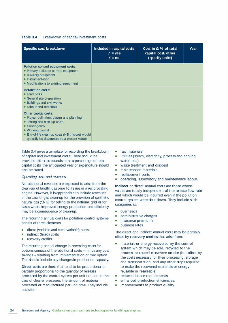
Table 3.4 gives a template for recording the breakdownof capital and investment costs. These should beprovided either as pounds or as a percentage of totalcapital costs; the anticipated year of expenditure shouldalso be stated.
Operating costs and revenues
No additional revenues are expected to arise from theclean-up of landfill gas prior to its use in a reciprocatingengine. However, it is appropriate to include revenuesin the case of gas clean-up for the provision of syntheticnatural gas (SNG) for selling to the national grid or forcases where improved energy production and efficiencymay be a consequence of clean-up.
The recurring annual costs for pollution control systemsconsist of three elements:
● direct (variable and semi-variable) costs● indirect (fixed) costs● recovery credits.
The recurring annual change in operating costs foroptions consists of the additional costs – minus any costsavings – resulting from implementation of that option.This should include any changes in production capacity.
Direct costs are those that tend to be proportional orpartially proportional to the quantity of releasesprocessed by the control system per unit time or, in thecase of cleaner processes, the amount of materialprocessed or manufactured per unit time. They includecosts for:
● raw materials● utilities (steam, electricity, process and cooling
water, etc.)● waste treatment and disposal● maintenance materials● replacement parts● operating, supervisory and maintenance labour.
Indirect or ‘fixed’ annual costs are those whosevalues are totally independent of the release flow rateand which would be incurred even if the pollutioncontrol system were shut down. They include suchcategories as:
● overheads● administrative charges● insurance premiums● business rates.
The direct and indirect annual costs may be partiallyoffset by recovery credits that arise from:
● materials or energy recovered by the control system which may be sold, recycled to the process, or reused elsewhere on-site (but offset by the costs necessary for their processing, storage and transportation, and any other steps required to make the recovered materials or energy reusable or resaleable);
● reduced labour requirements;● enhanced production efficiencies;● improvements to product quality.
Environment Agency Guidance on gas treatment technologies for landfill gas engines24
Table 3.4 Breakdown of capital/investment costs
Pollution control equipment costs:● Primary pollution control equipment● Auxiliary equipment● Instrumentation● Modifications to existing equipment
Installation costs:● Land costs● General site preparation● Buildings and civil works● Labour and materials
Other capital costs:● Project definition, design and planning● Testing and start-up costs● Contingency● Working capital● End-of-life clean-up costs (NB this cost would● typically be discounted to a present value)
Specific cost breakdown Included in capital costs Cost in £/% of total Year✓ = yes capital cost/other✗ = no (specify units)
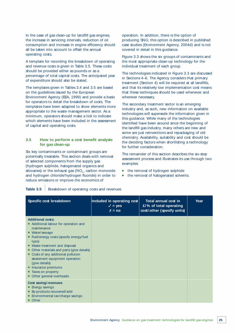
Environment Agency Guidance on gas treatment technologies for landfill gas engines 25
Table 3.5 Breakdown of operating costs and revenues
Additional costs:● Additional labour for operation and● maintenance● Water/sewage● Fuel/energy costs (specify energy/fuel● type)● Waste treatment and disposal● Other materials and parts (give details)● Costs of any additional pollution● abatement equipment operation● (give details)● Insurance premiums● Taxes on property● Other general overheads
Cost saving/revenues:● Energy savings● By-products recovered/sold● Environmental tax/charge savings● Other
Specific cost breakdown Included in operating cost Total annual cost in Year✓ = yes £/% of total operating✗ = no cost/other (specify units)
In the case of gas clean-up for landfill gas engines,the increase in servicing intervals, reduction of oilconsumption and increase in engine efficiency shouldall be taken into account to offset the annualoperating costs.
A template for recording the breakdown of operatingand revenue costs is given in Table 3.5. These costsshould be provided either as pounds or as apercentage of total capital costs. The anticipated yearof expenditure should also be stated.
The templates given in Tables 3.4 and 3.5 are basedon the guidelines issued by the EuropeanEnvironment Agency (EEA, 1999) and provide a basisfor operators to detail the breakdown of costs. Thetemplates have been adapted to show elements moreappropriate to the waste management sector. As aminimum, operators should make a tick to indicatewhich elements have been included in the assessmentof capital and operating costs.
3.5 How to perform a cost benefit analysis for gas clean-up
Six key contaminants or contaminant groups arepotentially treatable. This section deals with removalof selected components from the supply gas(hydrogen sulphide, halogenated organics andsiloxanes) or the exhaust gas (NOx, carbon monoxideand hydrogen chloride/hydrogen fluoride) in order toreduce emissions or improve the economics of
operation. In addition, there is the option ofproducing SNG; this option is described in publishedcase studies (Environment Agency, 2004d) and is notcovered in detail in this guidance.
Figure 3.3 shows the six groups of contaminants andthe most appropriate clean-up technology for theindividual treatment of each group.
The technologies indicated in Figure 3.3 are discussedin Sections 4–6. The Agency considers that primarytreatment (Section 4) will be required at all landfills,and that its relatively low implementation cost meansthat these techniques should be used whenever andwherever necessary.
The secondary treatment sector is an emergingindustry and, as such, new information on availabletechnologies will supersede the information given inthis guidance. While many of the technologiesidentified have been around since the beginning ofthe landfill gas industry, many others are new andsome are just reinventions and repackaging of oldchemistry. Availability, suitability and cost should bethe deciding factors when shortlisting a technologyfor further consideration.
The remainder of this section describes the six-stepassessment process and illustrates its use through twoexamples:
● the removal of hydrogen sulphide● the removal of halogenated solvents.

Environment Agency Guidance on gas treatment technologies for landfill gas engines26
Hyd
rog
ensu
lph
ide
Dry
scr
ubbi
ng
Wat
er s
crub
bing
Solv
ent
scru
bbin
g
Hal
og
enat
edo
rgan
ics
Wat
er s
crub
bing
Solv
ent
scru
bbin
g
Mem
bran
e se
par
atio
n
Pres
sure
sw
ing
adso
rptio
n
Mol
ecul
ar s
ieve
Cry
ogen
ic
CO
2liq
uefa
ctio
n
Silo
xan
es
Act
ivat
ed c
arbo
n
Act
ivat
ed c
arbo
n +
heat
exc
hang
er
Act
ivat
ed c
arbo
n +
chill
ing
Act
ivat
ed c
arbo
n +
cryo
geni
c tr
eatm
ent
Wat
er w
ash
In-e
ngin
e ch
emic
alin
ject
ion
NO
x
Engi
nem
anag
emen
tsy
stem
s
Wat
er in
ject
ion
Exha
ust
gas
reci
rcul
atio
n
Cat
alyt
ic o
xida
tion
(als
o re
qui
res
pre
trea
tmen
t of
halo
gena
ted
orga
nics
)
CO
PRE-
CO
MBU
STIO
NTR
EATM
ENT
IN-E
NG
INE
AN
D P
OST
-C
OM
BUST
ION
TRE
ATM
ENTS
Ther
mal
oxi
datio
n
Oxy
gen
enric
hmen
t at
in
let
(pot
entia
l for
high
NO
x)
HC
I/H
F
Cat
alyt
icsc
rubb
ing
and
solid
ifica
tion
Co
mp
on
ents
req
uiri
ng
tre
atm
ent
Fig
ure
3.3
Gas
cle
an-u
p t
echn
olog
y op
tions
for
par
ticul
ar c
omp
onen
ts r
equi
ring
trea
tmen
t
Environment Agency Guidance on gas treatment technologies for landfill gas engines 27
3.5.1 Step 1: define the objective and the optionsto be considered
The first step in the assessment process is to:
● identify the objective(s) of the assessment● list the potential options to be considered.
Example 1
Objective
Treatment of high hydrogen sulphideconcentrations in landfill gas is required to reduceengine wear and subsequent atmosphericemissions of SOx in a sensitive location – a needindicated by site-specific risk assessment).
Possible clean-up options
Hydrogen sulphide clean-up can be achieved bydry or wet desulphurisation. Both techniques arepre-combustion, secondary clean-up technologiesand information on these can be found in Section5 and case studies 1–4 (Environment Agency,2004d).
Example 2
Objective
Treatment of high chlorine concentrations in thesupply gas or treatment of high HCl emissions inthe exhaust – a need indicated by site-specific riskassessment.
Possible clean-up options
Clean-up of chlorine in the supply gas can beachieved by pressure water scrubbing, pressureswing adsorption, or membrane separationtechniques as pre-combustion, secondary clean-uptechniques (see Section 5 and case studies 5–11described in Environment Agency, 2004d), or byexhaust dry scrubbing (see Section 6 and casestudy 18).
3.5.2 Step 2: quantify the emissions from each treatment option
When emission standards have been set by theregulator, it is a straightforward task to ascertain thelevel of clean-up required to achieve this limit.
The degree of gas clean-up required will depend onthe amount by which the emission exceeds thestandard. For example, a technology offering 99.9per cent clean-up would not be justified if theemissions are only 25 per cent above the emission
standard and there is an alternative technology thatcan meet the standard.
In certain circumstances, a ‘no action’ baselinecondition should be considered as well as thetechnologies to help assess the environmental benefitof any clean-up treatment considered.
Example 1
Table 3.6 shows that the efficiency of drydesulphurisation increases from 75 to 98 per centwith increasing sulphur load in the supply gas. Thissite has a total sulphur content of approximately2,700 mg S/Nm3 in the supply gas. This isequivalent to case study 2b (Environment Agency,(2004d) and 98 per cent clean-up could beachieved (giving a supply gas quality to the gasengine of 135 mg S/Nm3). Once combusted, it isassumed that the exhaust will contain ~1 per centof this as hydrogen sulphide, i.e. ~1.4 mg/Nm3.
Table 3.6 also shows that wet desulphurisationachieves 99 per cent gas clean-up, although theinformation does not indicate whether this isachievable with the higher sulphur loadings foundin this landfill gas supply.
Both technologies would be suitable for furtherconsideration.
Example 2
Table 3.6 shows that clean-up efficiencies vary forthe component of interest. In this case, theremoval of chlorinated compounds should beachievable at 95 per cent efficiency for all thesecondary pretreatment options (pressure waterscrubbing, pressure swing adsorption, ormembrane separation) and at 93 per cent for post-combustion dry scrubbing.
The supply gas contains 560 mg Cl/Nm3 and so alltechnologies are appropriate.
The impact of the supply gas quality on emissionsmust be calculated for components in the supply gasthat affect the emissions of other gases. For example,removal of chlorine in the supply gas in Example 2may reduce emissions of PCDDs and PCDFs from theexhaust stack.
Quantification of the emissions and emissionsreduction from each treatment option can be madeon the basis of measurements at an existinginstallation. Alternatively, if these do not exist, theycan be made using a manufacturer’s information on
the process. However, both methods have inherentuncertainties. Table 3.6 gives some estimates ofemissions reduction due to variations in stack heightfor the processes described in some of the casestudies (see Environment Agency, 2004d); these dataare used to illustrate the examples in this section.
If more complex modelling is not required, HorizontalGuidance Note H1 and other Agency guidance(Environment Agency, 2002a and 2004b) recommendcalculation of the contribution from the landfill gasengine to emissions to air according to the followingformula:
PCair = GLC x RR
where:
PCair = process contribution (µg/m3)
RR = release rate of substance in g/second
GLC = maximum average ground level concentration for unit mass release rate (µg/m3/g/s),based on the annual average for long-term releases and the hourly average for short-term releases.
Guidance on the management of landfill gas(Environment Agency, 2004b) contains tables ofconservative ground level concentrations appropriatefor landfill gas engines.
Releases that warrant no further consideration (e.g.no action on emissions clean-up is required) aredefined as follows:
● An emission is insignificant where PC <1 per cent of the environmental benchmark (long-term).
● An emission is insignificant where PC <10 per centof the environmental benchmark (short-term).
Further advice on assessing the importance of landfillgas engine emissions is given in Guidance on themanagement of landfill gas (Environment Agency,2004b) and information on discharge stack heightsfor polluting emissions is given in Technical GuidanceNote (Dispersion) D1 (HMIP, 1993).
3.5.3 Step 3: quantify the environmental impactsresulting from the different options
Each clean-up option will have its own environmentalimpact. The pollutant abatement process willinevitably produce other waste streams and theenvironmental impact of these must also beconsidered. These waste arisings may be hazardousand expensive to dispose of, or may affect another
Environment Agency Guidance on gas treatment technologies for landfill gas engines28
receptor such as groundwater. Unfortunately,manufacturers tend to place less emphasis on wastestreams produced by gas clean-up processes than onthe benefits of their technologies.
It would be inappropriate to select a clean-up optionthat had a significant environmental impact inanother media. For example, it might be harder tomanage a hazardous waste oil or sludge generatedduring a clean-up process than the primaryatmospheric emission.
Examples 1 and 2
Given the lack of much information on the likelywastes arising from the possible clean-uptechnologies, they are considered to have an equalnegative environmental impact.
3.5.4 Step 4: compare options and best environmental performance ranking
Examples 1 and 2
Table 3.6 gives examples of processes that canremove hydrogen sulphide or halogenated organiccompounds (or both) from landfill gas. Nearly allhave high clean-up efficiencies, suggesting thatthere would be little difference in the emissionsreduction achieved by the different technologies.In such cases, the capital, operation andmaintenance (O&M) costs would be the drivingfactor in the choice of technology.
If a full CBA is not carried out, good indicators forassessing comparative costs are:
● a comparison of the capital costs● the cost per tonne of pollutant abated● annual operating costs.
However, such an analysis requires comparableinformation for all options.
Table 3.6 indicates that the technology in case study2 had a lower clean-up efficiency at lower pollutantloadings. However, other technologies could performbetter at lower pollutant loadings than higher ones.The capability of the technology to treat the gas atthe site thus has an additional bearing on thecomparison of technologies for their environmentalimpact.
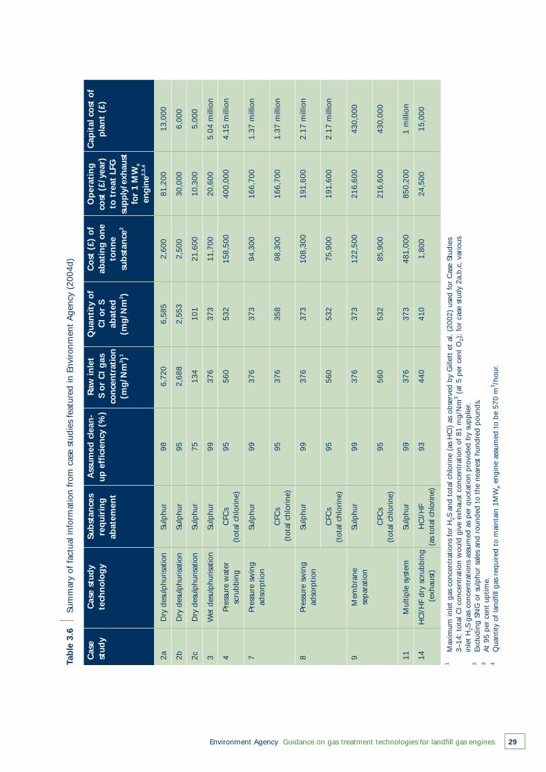
Environment Agency Guidance on gas treatment technologies for landfill gas engines 29
Tab
le 3
.6
Sum
mar
y of
fac
tual
info
rmat
ion
from
cas
e st
udie
s fe
atur
ed in
Env
ironm
ent
Age
ncy
(200
4d)
2aD
ry d
esul
phur
isatio
nSu
lphu
r98
6,72
06,
585
2,60
081
,200
13,0
00
2bD
ry d
esul
phur
isatio
nSu
lphu
r95
2,68
82,
553
2,50
030
,000
6,00
0
2cD
ry d
esul
phur
isatio
nSu
lphu
r75
134
101
21,6
0010
,300
5,00
0
3W
et d
esul
phur
isatio
nSu
lphu
r99
376
373
11,7
0020
,600
5.04
mill
ion
4Pr
essu
re w
ater
CFC
s95
560
532
158,
500
400,
000
4.15
mill
ion
scru
bbin
g(t
otal
chl
orin
e)
7Pr
essu
re s
win
gSu
lphu
r99
376
373
94,3
0016
6,70
01.
37 m
illio
nad
sorp
tion
CFC
s95
376
358
98,3
0016
6,70
01.
37 m
illio
n(t
otal
chl
orin
e)
8Pr
essu
re s
win
gSu
lphu
r99
376
373
108,
300
191,
600
2.17
mill
ion
adso
rptio
n
CFC
s 95
560
532
75,9
0019
1,60
02.
17 m
illio
n(t
otal
chl
orin
e)
9M
embr
ane
Sulp
hur
9937
637
312
2,50
021
6,60
043
0,00
0se
par
atio
n
CFC
s95
560
532
85,9
0021
6,60
043
0,00
0(t
otal
chl
orin
e)
11M
ultip
le s
yste
mSu
lphu
r99
376
373
481,
000
850,
200
1 m
illio
n
14H
Cl/
HF
dry
scru
bbin
gH
Cl/
HF
9344
041
01,
800
24,5
0015
,000
(exh
aust
)(a
s to
tal c
hlor
ine)
Cas
eC
ase
stud
y Su
bst
ance
sA
ssum
ed c
lean
-R
aw in
let
Qua
nti
ty o
fC
ost
(£)
of
Op
erat
ing
Cap
ital
co
st o
fst
udy
tech
no
log
yre
qui
rin
gup
eff
icie
ncy
(%
)S
or
CI
gas
CI
or
Sab
atin
g o
ne
cost
(£/
year
)p
lan
t (£
)ab
atem
ent
con
cen
trat
ion
abat
edto
nn
eto
tre
at L
FG(m
g/N
m3 )1
(mg
/Nm
3 )su
bst
ance
2su
pp
ly/e
xhau
stfo
r 1
MW
e
eng
ine2,
3,4
1M
axim
um in
let
gas
conc
entr
atio
ns f
or H
2S a
nd t
otal
chl
orin
e (a
s H
Cl)
as o
bser
ved
by G
illet
t et
al.
(200
2) u
sed
for
Cas
e St
udie
s 3–
14;
tota
l Cl c
once
ntra
tion
wou
ld g
ive
exha
ust
conc
entr
atio
n of
81
mg/
Nm
3(a
t 5
per
cen
t O
2);
for
case
stu
dy 2
a,b,
c, v
ario
us
inle
t H
2S g
as c
once
ntra
tions
ass
umed
as
per
quo
tatio
n p
rovi
ded
by s
upp
lier.
2Ex
clud
ing
SNG
or
sulp
hur
sale
s an
d ro
unde
d to
the
nea
rest
hun
dred
pou
nds.
3A
t 95
per
cen
t up
time.
4Q
uant
ity o
f la
ndfil
l gas
req
uire
d to
mai
ntai
n 1M
We
engi
ne a
ssum
ed t
o be
570
m3 /h
our.
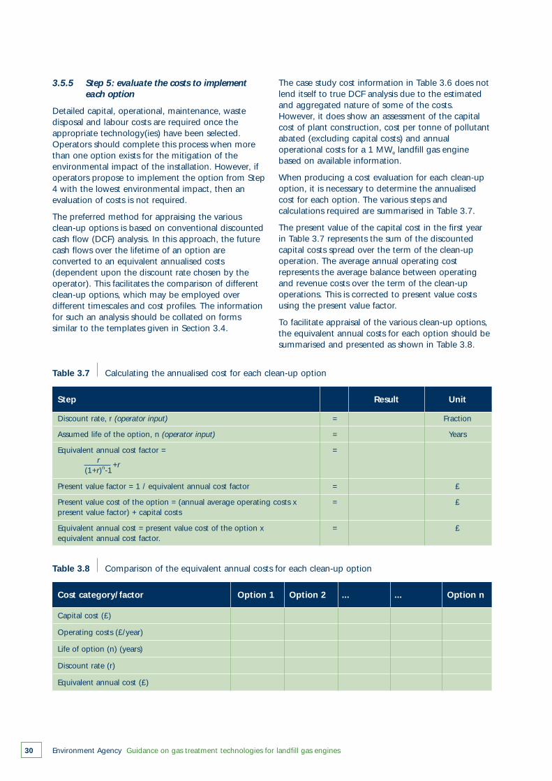
Environment Agency Guidance on gas treatment technologies for landfill gas engines30
3.5.5 Step 5: evaluate the costs to implement each option
Detailed capital, operational, maintenance, wastedisposal and labour costs are required once theappropriate technology(ies) have been selected.Operators should complete this process when morethan one option exists for the mitigation of theenvironmental impact of the installation. However, ifoperators propose to implement the option from Step4 with the lowest environmental impact, then anevaluation of costs is not required.
The preferred method for appraising the variousclean-up options is based on conventional discountedcash flow (DCF) analysis. In this approach, the futurecash flows over the lifetime of an option areconverted to an equivalent annualised costs(dependent upon the discount rate chosen by theoperator). This facilitates the comparison of differentclean-up options, which may be employed overdifferent timescales and cost profiles. The informationfor such an analysis should be collated on formssimilar to the templates given in Section 3.4.
Table 3.7 Calculating the annualised cost for each clean-up option
Discount rate, r (operator input) = Fraction
Assumed life of the option, n (operator input) = Years
Equivalent annual cost factor = =
Present value factor = 1 / equivalent annual cost factor = £
Present value cost of the option = (annual average operating costs x = £present value factor) + capital costs
Equivalent annual cost = present value cost of the option x = £equivalent annual cost factor.
Step Result Unit
r(1+r)n-1
+r
Table 3.8 Comparison of the equivalent annual costs for each clean-up option
Capital cost (£)
Operating costs (£/year)
Life of option (n) (years)
Discount rate (r)
Equivalent annual cost (£)
Cost category/factor Option 1 Option 2 ... ... Option n
The case study cost information in Table 3.6 does notlend itself to true DCF analysis due to the estimatedand aggregated nature of some of the costs.However, it does show an assessment of the capitalcost of plant construction, cost per tonne of pollutantabated (excluding capital costs) and annualoperational costs for a 1 MWe landfill gas enginebased on available information.
When producing a cost evaluation for each clean-upoption, it is necessary to determine the annualisedcost for each option. The various steps andcalculations required are summarised in Table 3.7.
The present value of the capital cost in the first yearin Table 3.7 represents the sum of the discountedcapital costs spread over the term of the clean-upoperation. The average annual operating costrepresents the average balance between operatingand revenue costs over the term of the clean-upoperations. This is corrected to present value costsusing the present value factor.
To facilitate appraisal of the various clean-up options,the equivalent annual costs for each option should besummarised and presented as shown in Table 3.8.
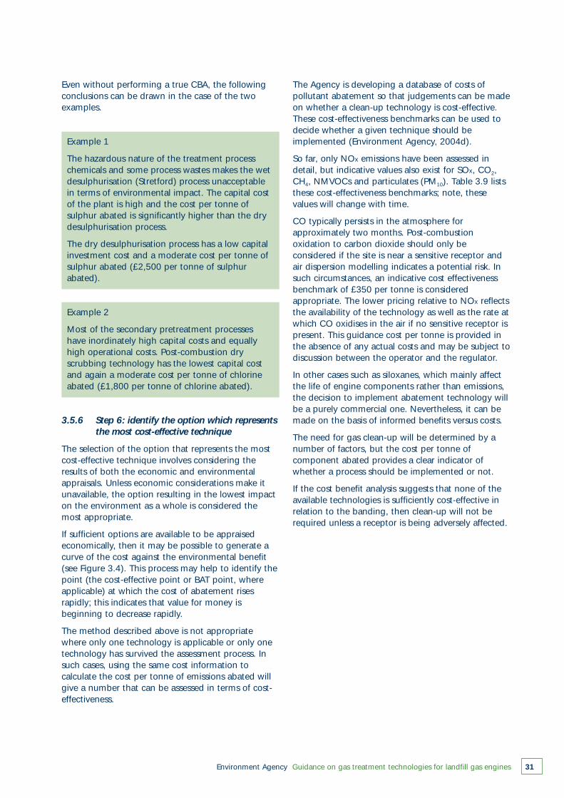
Environment Agency Guidance on gas treatment technologies for landfill gas engines 31
Even without performing a true CBA, the followingconclusions can be drawn in the case of the twoexamples.
Example 1
The hazardous nature of the treatment processchemicals and some process wastes makes the wetdesulphurisation (Stretford) process unacceptablein terms of environmental impact. The capital costof the plant is high and the cost per tonne ofsulphur abated is significantly higher than the drydesulphurisation process.
The dry desulphurisation process has a low capitalinvestment cost and a moderate cost per tonne ofsulphur abated (£2,500 per tonne of sulphurabated).
Example 2
Most of the secondary pretreatment processeshave inordinately high capital costs and equallyhigh operational costs. Post-combustion dryscrubbing technology has the lowest capital costand again a moderate cost per tonne of chlorineabated (£1,800 per tonne of chlorine abated).
3.5.6 Step 6: identify the option which representsthe most cost-effective technique
The selection of the option that represents the mostcost-effective technique involves considering theresults of both the economic and environmentalappraisals. Unless economic considerations make itunavailable, the option resulting in the lowest impacton the environment as a whole is considered themost appropriate.
If sufficient options are available to be appraisedeconomically, then it may be possible to generate acurve of the cost against the environmental benefit(see Figure 3.4). This process may help to identify thepoint (the cost-effective point or BAT point, whereapplicable) at which the cost of abatement risesrapidly; this indicates that value for money isbeginning to decrease rapidly.
The method described above is not appropriatewhere only one technology is applicable or only onetechnology has survived the assessment process. Insuch cases, using the same cost information tocalculate the cost per tonne of emissions abated willgive a number that can be assessed in terms of cost-effectiveness.
The Agency is developing a database of costs ofpollutant abatement so that judgements can be madeon whether a clean-up technology is cost-effective.These cost-effectiveness benchmarks can be used todecide whether a given technique should beimplemented (Environment Agency, 2004d).
So far, only NOx emissions have been assessed indetail, but indicative values also exist for SOx, CO2,CH4, NMVOCs and particulates (PM10). Table 3.9 liststhese cost-effectiveness benchmarks; note, thesevalues will change with time.
CO typically persists in the atmosphere forapproximately two months. Post-combustionoxidation to carbon dioxide should only beconsidered if the site is near a sensitive receptor andair dispersion modelling indicates a potential risk. Insuch circumstances, an indicative cost effectivenessbenchmark of £350 per tonne is consideredappropriate. The lower pricing relative to NOx reflectsthe availability of the technology as well as the rate atwhich CO oxidises in the air if no sensitive receptor ispresent. This guidance cost per tonne is provided inthe absence of any actual costs and may be subject todiscussion between the operator and the regulator.
In other cases such as siloxanes, which mainly affectthe life of engine components rather than emissions,the decision to implement abatement technology willbe a purely commercial one. Nevertheless, it can bemade on the basis of informed benefits versus costs.
The need for gas clean-up will be determined by anumber of factors, but the cost per tonne ofcomponent abated provides a clear indicator ofwhether a process should be implemented or not.
If the cost benefit analysis suggests that none of theavailable technologies is sufficiently cost-effective inrelation to the banding, then clean-up will not berequired unless a receptor is being adversely affected.
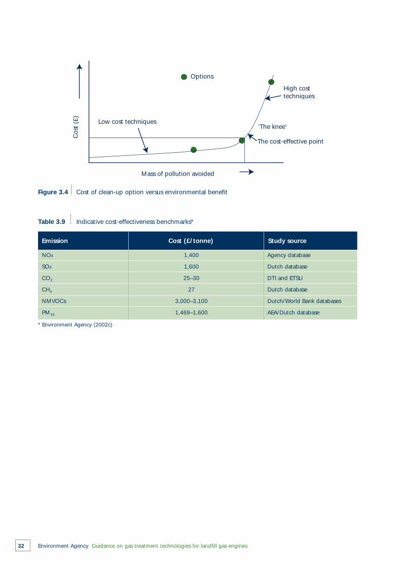
Environment Agency Guidance on gas treatment technologies for landfill gas engines32
Options
Low cost techniques
Mass of pollution avoided
Cos
t (£
)
High costtechniques
'The knee'
The cost-effective point
Figure 3.4 Cost of clean-up option versus environmental benefit
Table 3.9 Indicative cost-effectiveness benchmarks*
NOx 1,400 Agency database
SOx 1,600 Dutch database
CO2 25–30 DTI and ETSU
CH4 27 Dutch database
NMVOCs 3,000–3,100 Dutch/World Bank databases
PM10 1,469–1,600 AEA/Dutch database
Emission Cost (£/tonne) Study source
* Environment Agency (2002c)
Environment Agency Guidance on gas treatment technologies for landfill gas engines 33
4
Primary pretreatment technologies
Primary pretreatment technologies represent the firststage in reducing the amount of contaminants in thelandfill gas and typically use simple physical processoperations. The main contaminants removed (orreduced) are:
● water (referred to as ‘condensate’)● particulates.
These technologies have been in use for many yearsand are now a relatively standard element of activelandfill gas management plants. Typical equipmentand its operation are described below.
4.1 Water/condensate knockout
The presence of liquid water in landfill gas pipeworkcan have a detrimental effect on plant performance.First, the accumulation of water reduces the spaceavailable for gas flow and raises the pressure loss.Secondly, the unstable nature of two-phase flow (i.e.liquid and gas combined) can give rise to oscillations,which in turn, make it difficult to achieve a steadyand controllable operation. The presence ofcontaminated water can also lead to deposits on thepipe walls, which reduce the smoothness and furtherincrease the pressure loss. The presence of liquidwater in landfill gas pipes should thus be bothcontrolled and minimised.
Depending on the source of the gas and theapplication or proposed use of the treated landfill gas,three components can be treated. These are:
● slugs of liquid● gas-liquid foam● uncondensed water vapour.
The level of complexity (and therefore cost) increasesdown this list; hence, many installations in the UK relysolely on passive ‘slug catching’ vessels. However,foam and droplet arresting systems have beenadopted in some schemes to minimise the effects onengine intake and control systems. Removal ofuncondensed vapour is not often carried out,although there are examples in the UK of plant thattreats the landfill gas to yield a dew point of 2°C. The
basic principles of these treatment options aredescribed below.
4.1.1 Liquid water capture
In-line de-watering is frequently adopted by landfilloperators and is usually installed within the landfillgas collection network. However, there is invariably aneed to incorporate additional control measures toprevent onward transmission of liquid water. In somecases, drains and water traps may be adequate for aparticular supply gas specification.
A further common practice – usually forming the finalelement of de-watering – is a knockout drum. This isoften called a ‘condensate knockout pot’ – andoccasionally a ‘slug catcher’ – and is located as closeas practicable to the inlet to the gas booster. Thepurpose of the knockout drum is to lower the gasvelocity sufficiently for ‘dropout’ of liquid, which canthen be drained or pumped to discharge. Suchdevices are simple and capable of handling large gasflows (up to 10,000 m3/hour) and of removing >1litre/minute of water (see Figure 4.1).
4.1.2 Foam removal
One refinement of water control systems is theincorporation of coalescing (or demisting) meshes inthe gas pipes entering and leaving a condensateknockout drum. These meshes collapse entrainedfoam and prevent carryover. Typically, the meshes arewoven stainless steel pads which provide a largesurface area to trap the foam and allow it to drainunder gravity to the collection drum.
As an alternative (or in addition) to the knockoutdrum, some equipment manufacturers providecyclones that impart swirl to the incoming gas flowand thereby enhance the rate of liquid removal fromthe gas stream.
Several elements (e.g. de-watering manifold,knockout drum and secondary cyclone vessel) areoften built into a skid-mounted module that is linkeddirectly to the landfill gas booster inlet. Cyclones arereported by manufacturers to capture 99 per cent ofdroplets greater than 10 µm.
1 High efficiency knockout cyclone gas seperators offered by Kelburn Engineering Ltd.
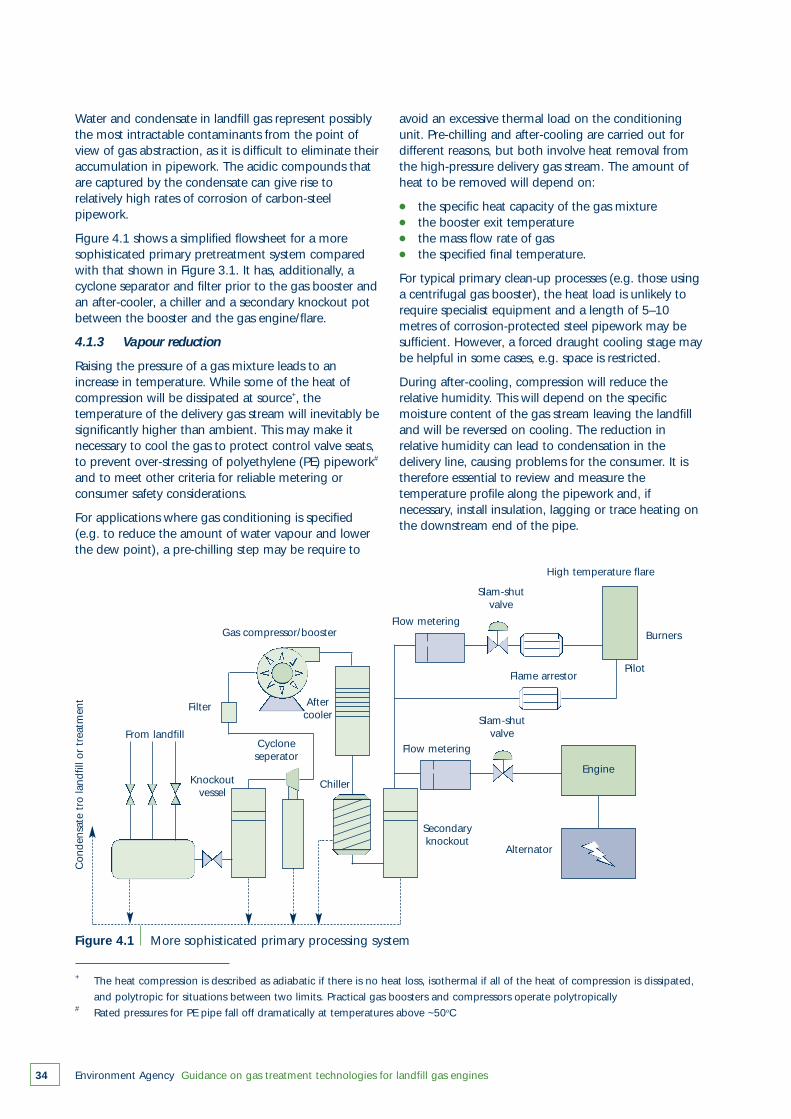
Water and condensate in landfill gas represent possiblythe most intractable contaminants from the point ofview of gas abstraction, as it is difficult to eliminate theiraccumulation in pipework. The acidic compounds thatare captured by the condensate can give rise torelatively high rates of corrosion of carbon-steelpipework.
Figure 4.1 shows a simplified flowsheet for a moresophisticated primary pretreatment system comparedwith that shown in Figure 3.1. It has, additionally, acyclone separator and filter prior to the gas booster andan after-cooler, a chiller and a secondary knockout potbetween the booster and the gas engine/flare.
4.1.3 Vapour reduction
Raising the pressure of a gas mixture leads to anincrease in temperature. While some of the heat ofcompression will be dissipated at source+, thetemperature of the delivery gas stream will inevitably besignificantly higher than ambient. This may make itnecessary to cool the gas to protect control valve seats,to prevent over-stressing of polyethylene (PE) pipework#
and to meet other criteria for reliable metering orconsumer safety considerations.
For applications where gas conditioning is specified(e.g. to reduce the amount of water vapour and lowerthe dew point), a pre-chilling step may be require to
Environment Agency Guidance on gas treatment technologies for landfill gas engines34
From landfill
Filter Aftercooler
ChillerKnockoutvessel
Secondaryknockout
Gas compressor/booster
Con
dens
ate
tro
land
fill o
r tr
eatm
ent
Flow metering
Flow metering
Slam-shutvalve
Slam-shutvalve
Flame arrestor
Engine
Alternator
High temperature flare
Burners
Pilot
Cycloneseperator
Figure 4.1 More sophisticated primary processing system
avoid an excessive thermal load on the conditioningunit. Pre-chilling and after-cooling are carried out fordifferent reasons, but both involve heat removal fromthe high-pressure delivery gas stream. The amount ofheat to be removed will depend on:
● the specific heat capacity of the gas mixture● the booster exit temperature● the mass flow rate of gas● the specified final temperature.
For typical primary clean-up processes (e.g. those usinga centrifugal gas booster), the heat load is unlikely torequire specialist equipment and a length of 5–10metres of corrosion-protected steel pipework may besufficient. However, a forced draught cooling stage maybe helpful in some cases, e.g. space is restricted.
During after-cooling, compression will reduce therelative humidity. This will depend on the specificmoisture content of the gas stream leaving the landfilland will be reversed on cooling. The reduction inrelative humidity can lead to condensation in thedelivery line, causing problems for the consumer. It istherefore essential to review and measure thetemperature profile along the pipework and, ifnecessary, install insulation, lagging or trace heating onthe downstream end of the pipe.
+ The heat compression is described as adiabatic if there is no heat loss, isothermal if all of the heat of compression is dissipated,
and polytropic for situations between two limits. Practical gas boosters and compressors operate polytropically# Rated pressures for PE pipe fall off dramatically at temperatures above ~50oC
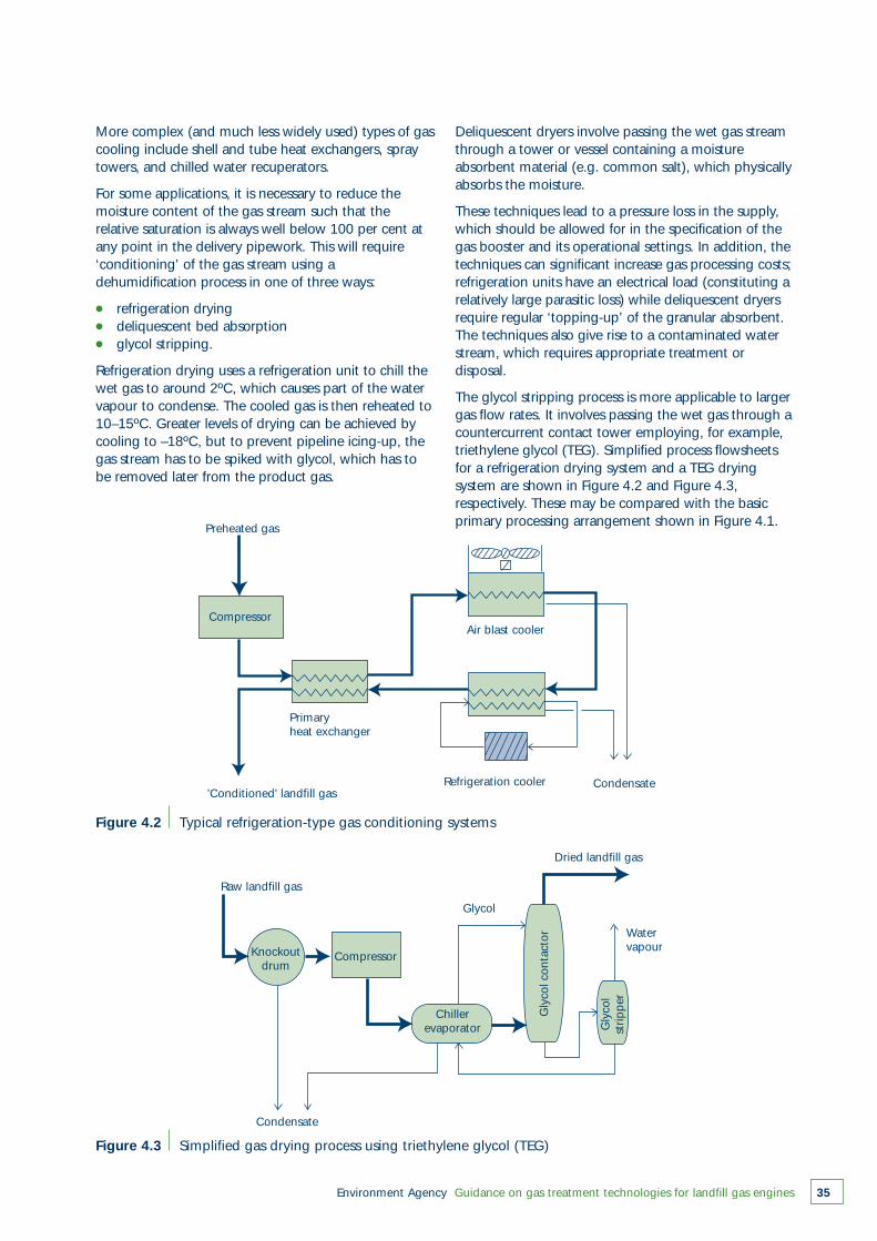
More complex (and much less widely used) types of gascooling include shell and tube heat exchangers, spraytowers, and chilled water recuperators.
For some applications, it is necessary to reduce themoisture content of the gas stream such that therelative saturation is always well below 100 per cent atany point in the delivery pipework. This will require‘conditioning’ of the gas stream using adehumidification process in one of three ways:
● refrigeration drying● deliquescent bed absorption● glycol stripping.
Refrigeration drying uses a refrigeration unit to chill thewet gas to around 2ºC, which causes part of the watervapour to condense. The cooled gas is then reheated to10–15ºC. Greater levels of drying can be achieved bycooling to –18ºC, but to prevent pipeline icing-up, thegas stream has to be spiked with glycol, which has tobe removed later from the product gas.
Environment Agency Guidance on gas treatment technologies for landfill gas engines 35
Figure 4.2 Typical refrigeration-type gas conditioning systems
Figure 4.3 Simplified gas drying process using triethylene glycol (TEG)
Preheated gas
Compressor
Primaryheat exchanger
'Conditioned' landfill gasRefrigeration cooler
Air blast cooler
Condensate
Raw landfill gas
Condensate
Glycol
Dried landfill gas
Water vapourKnockout
drumCompressor
Chillerevaporator
Gly
col c
onta
ctor
Gly
col
strip
per
Deliquescent dryers involve passing the wet gas streamthrough a tower or vessel containing a moistureabsorbent material (e.g. common salt), which physicallyabsorbs the moisture.
These techniques lead to a pressure loss in the supply,which should be allowed for in the specification of thegas booster and its operational settings. In addition, thetechniques can significant increase gas processing costs;refrigeration units have an electrical load (constituting arelatively large parasitic loss) while deliquescent dryersrequire regular ‘topping-up’ of the granular absorbent.The techniques also give rise to a contaminated waterstream, which requires appropriate treatment ordisposal.
The glycol stripping process is more applicable to largergas flow rates. It involves passing the wet gas through acountercurrent contact tower employing, for example,triethylene glycol (TEG). Simplified process flowsheetsfor a refrigeration drying system and a TEG dryingsystem are shown in Figure 4.2 and Figure 4.3,respectively. These may be compared with the basicprimary processing arrangement shown in Figure 4.1.
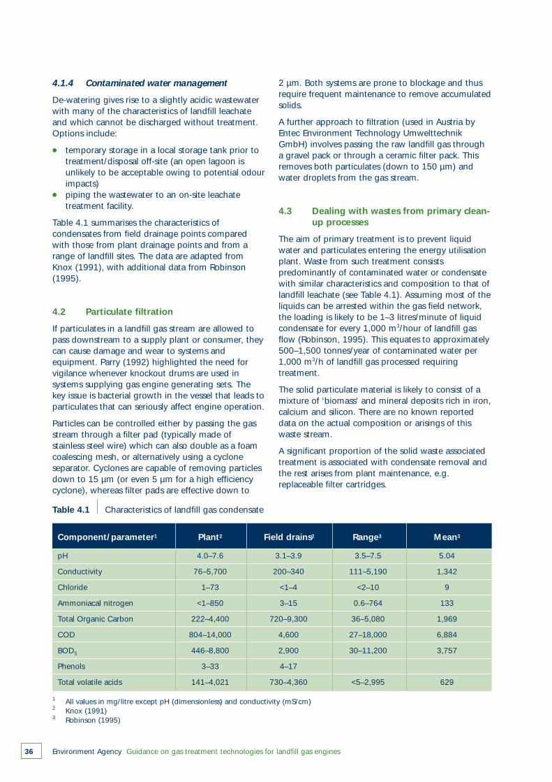
Environment Agency Guidance on gas treatment technologies for landfill gas engines36
4.1.4 Contaminated water management
De-watering gives rise to a slightly acidic wastewaterwith many of the characteristics of landfill leachateand which cannot be discharged without treatment.Options include:
● temporary storage in a local storage tank prior to treatment/disposal off-site (an open lagoon is unlikely to be acceptable owing to potential odourimpacts)
● piping the wastewater to an on-site leachate treatment facility.
Table 4.1 summarises the characteristics ofcondensates from field drainage points comparedwith those from plant drainage points and from arange of landfill sites. The data are adapted fromKnox (1991), with additional data from Robinson(1995).
4.2 Particulate filtration
If particulates in a landfill gas stream are allowed topass downstream to a supply plant or consumer, theycan cause damage and wear to systems andequipment. Parry (1992) highlighted the need forvigilance whenever knockout drums are used insystems supplying gas engine generating sets. Thekey issue is bacterial growth in the vessel that leads toparticulates that can seriously affect engine operation.
Particles can be controlled either by passing the gasstream through a filter pad (typically made ofstainless steel wire) which can also double as a foamcoalescing mesh, or alternatively using a cycloneseparator. Cyclones are capable of removing particlesdown to 15 µm (or even 5 µm for a high efficiencycyclone), whereas filter pads are effective down to
Table 4.1 Characteristics of landfill gas condensate
pH 4.0–7.6 3.1–3.9 3.5–7.5 5.04
Conductivity 76–5,700 200–340 111–5,190 1,342
Chloride 1–73 <1–4 <2–10 9
Ammoniacal nitrogen <1–850 3–15 0.6–764 133
Total Organic Carbon 222–4,400 720–9,300 36–5,080 1,969
COD 804–14,000 4,600 27–18,000 6,884
BOD5 446–8,800 2,900 30–11,200 3,757
Phenols 3–33 4–17
Total volatile acids 141–4,021 730–4,360 <5–2,995 629
Component/parameter1 Plant2 Field drains2 Range3 Mean3
1 All values in mg/litre except pH (dimensionless) and conductivity (mS/cm)2 Knox (1991)3 Robinson (1995)
2 µm. Both systems are prone to blockage and thusrequire frequent maintenance to remove accumulatedsolids.
A further approach to filtration (used in Austria byEntec Environment Technology UmwelttechnikGmbH) involves passing the raw landfill gas througha gravel pack or through a ceramic filter pack. Thisremoves both particulates (down to 150 µm) andwater droplets from the gas stream.
4.3 Dealing with wastes from primary clean-up processes
The aim of primary treatment is to prevent liquidwater and particulates entering the energy utilisationplant. Waste from such treatment consistspredominantly of contaminated water or condensatewith similar characteristics and composition to that oflandfill leachate (see Table 4.1). Assuming most of theliquids can be arrested within the gas field network,the loading is likely to be 1–3 litres/minute of liquidcondensate for every 1,000 m3/hour of landfill gasflow (Robinson, 1995). This equates to approximately500–1,500 tonnes/year of contaminated water per1,000 m3/h of landfill gas processed requiringtreatment.
The solid particulate material is likely to consist of amixture of ‘biomass’ and mineral deposits rich in iron,calcium and silicon. There are no known reporteddata on the actual composition or arisings of thiswaste stream.
A significant proportion of the solid waste associatedtreatment is associated with condensate removal andthe rest arises from plant maintenance, e.g.replaceable filter cartridges.
Environment Agency Guidance on gas treatment technologies for landfill gas engines 37
5
Secondary pretreatment technologies
5.1 Introduction
In the UK, landfill gas used in utilisation plantcurrently receives only primary pretreatment.However, there is a range of processes that aredesigned to provide much greater gas cleaning thanis possible using just primary systems. Such processes,which include both physical and chemical treatments,can be defined collectively as secondarypretreatment.
There has been little uptake of secondarypretreatment in the UK, although advanced clean-upsystems have been considered by operators ofelectricity generating plant in the light of anincreasing number of engine failures.
The USA led the development of secondarypretreatment systems, where large-scale plant was inoperation over 20 years ago, primarily for theproduction of synthetic natural gas. Within the EU,there has been recent interest in producing SNG bycleaning-up landfill gas; some of the techniques usedin SNG manufacture are also applicable to landfill gaspretreatment for gas engines.
The following discussion is based on a review of theexperience in the USA and the Netherlands withclean-up technologies. However, the secondarypretreatment techniques described below are processapplications; they would need to be designed andtailored to meet individual site requirements.
Pre-combustion clean-up of landfill gas traceconstituents has no effect on bulk emissions of COand NOx and is therefore only useful in reducingaggressive gas constituents that either harm theengine or produce unacceptable emission levels. Thissection examines available secondary pretreatmentoptions for hydrogen sulphide, halogenatedcompounds and siloxanes. Gas engine operatorsmight consider these treatment options if:
● hydrogen sulphide, halogenated solvents, or siloxanes are causing engine wear;
● emissions of H2S, SO2, HCl, HF, PCDDs and PCDFs exceed safe concentrations as determined by site-specific risk assessment.
5.2 Hydrogen sulphide pretreatment
There are a number of methods of removing orstripping hydrogen sulphide from gas streams,involving both wet and dry scrubbing techniques.Wet scrubbing techniques are usually employed toremove not just hydrogen sulphide, but also anumber of other components.
5.2.1 Hydrogen sulphide dry scrubbing
An early solid chemical treatment for H2S, which wasemployed widely for coke-oven gas, was the use of an‘iron sponge’ or wood chips impregnated withhydrated ferric oxide (case study 1, EnvironmentAgency, 2004d). The hydrogen sulphide within thegas reacts with the ‘iron sponge’ to form ironsulphide, with clean-up efficiencies up to 99.98 percent.
Early utilisation schemes made use of iron oxideboxes to reduce the concentration of hydrogensulphide. For example, in the late 1970s, theCinnaminson landfill in New Jersey, USA, provided gaswith 62 per cent v/v methane to the Hoeganaes steelplant at a rate of around 300 m3/hour. The gas wastreated with partial success to reduce hydrogensulphide by passing it through a bed of woodshavings impregnated with iron oxide. Different scalesof operation have been employed ranging from gasflow rates of ~2,500m3 CH4/hour (e.g. Avenue CokingWorks) down to much smaller scale plants ~100 m3
CH4/hour (e.g. SCA paper recycling plant, Lucca,Italy; Camelshead Waste Water Treatment Works,Plymouth, UK).
The SCA paper recycling plant in Lucca uses two gaspurifier units (Varec Vapor Control Inc.), which canreduce outlet H2S concentrations to 4.5 ppm v/v. Thespent adsorption beds can be re-activated by airinjection, which converts the iron sulphide back toiron oxide and elemental sulphur. The operational lifeof a unit is five years.
A system marketed as Sulphur-Rite“ (Gas TechnologyProducts) uses an unspecified iron-based medium toform iron sulphide to treat operations with H2Semission loads of <180 kg/day with pre-engineered
Environment Agency Guidance on gas treatment technologies for landfill gas engines38
units handling gas flow rates up to 4,300 m3/hour(i.e. H2S gas concentrations <1,765 mg/m3). Thisproduct claims to remove 3–5 times more H2S than asimple iron sponge system. The system consists ofone or two vertical reacting vessels, and the spentmaterial is typically sent to landfill.
Activated carbon filters (as powder, granules or fibres)are generated chemically and/or in a hightemperature steam environment to produce anextensive network of impregnated pores. These poresprovide the sites for the physical adsorption of H2S(and also water, CO2 and halogenated compounds).These filters are most effectively used for polishinggases after other treatment(s), and the high cost offilter replacement/regeneration and the cost ofdisposing of the spent carbon make such schemesexpensive for landfill gas operations.
Another system marketed as GAS RAP® is described incase study 2 of R&D Technical Report P1-330/TR(Environment Agency, 2004d). This system has thepotential to achieve levels of 25–50 ppm H2S in thetreated gas from landfill gas supplied with typically100 ppm v/v H2S, and levels of 100–200 ppm for asupply with high H2S concentrations (> 2,000 ppmv/v). The technology appears to be most cost-effective for landfill gas with high H2S concentrations(i.e. > 2,000 ppm v/v).
5.2.2 Hydrogen sulphide wet scrubbing
Chemicals used in the wet scrubbing of H2S can besolid or liquid, and may be applied in batch contactortowers or injected directly into the gas pipeline. Theby-product of the reaction is usually separated anddisposed of as a waste. The chemical is consumedand the absorbent can be regenerated.
The Holmes-Stretford process is a liquid chemicalprocess that has been employed to remove H2S fromnumerous types of gas stream. This uses a causticwashing solution (containing sodium carbonate andpentavalent vanadium) to produce elemental sulphur.A catalyst of anthraquinone disulphonic acid (ADA)combined with air injection is used to regenerate (re-oxidise) the tetravalent vanadium and separate thesulphur. A removal efficiency of H2S of 99.99 per centcan be achieved using this process (Moyes et al.,1974), which at the Smithy Wood landfill (case study3, Environment Agency, 2004d) proved capable oftreating gas at 8,200 m3/hour with a hydrogensulphide loading of 103 kg/hour.
A proprietary liquid redox system that uses a chelatediron catalyst to convert H2S to elemental sulphur (LO-CAT® process, Gas Technology Products) is designedfor 99.9 per cent removal of H2S. The iron catalyst isheld in solution by organic chelating agents, which
prevent precipitation of iron sulphide or ironhydroxide such that the reduced (ferrous) iron can bere-oxidised to ferric iron in the oxidiser and thecatalyst regenerated for the absorber stage with theformation of elemental sulphur. This system has beenemployed at the Central Sanitary Landfill (BrowardCounty, Florida, USA) to treat 11,000 m3/hour oflandfill gas containing up to 5,000 ppm v/v of H2Sprior to use in gas turbines.
The landfill gas at Sonzay Landfill (Tours, France) hasbeen treated since 1994 using a fully operationalwater scrubbing operation with the capability toupgrade the gas for use as vehicle fuel (Balbo, 1997).The landfill gas is initially compressed to 1.4 MPa (14bar), water cooled and then passed through a water-packed countercurrent wet scrubber. This physicallyabsorbs most of the H22 and CO2 (both of whichhave higher relative aqueous solubility compared withCH4). The water is regenerated using ambient air andthe exhaust stream is cleaned using a biofilter. Thescrubbed gas is dried by passing it through dualadsorption columns (operational and regenerating)prior to secondary compression. This processproduces a compressed natural gas (CNG) ofbetween 86 and 97 per cent (v/v) CH4, with oxygen<0.5 per cent (v/v) and H2S <5 ppm v/v (Roe et al,1998). It is estimated that 2 litres of CNG can beproduced per tonne of landfilled waste over a 15-yearperiod (Balbo, 1997).
Other liquid absorption techniques use proprietarysolvents rather than water to selectively remove H2S(plus CO2 and halogenated compounds) from thelandfill gas stream. In this case, the reduced sulphurspecies can be recovered as elemental sulphur(typically at 95–99 per cent recovery rates for H2S).The solvent Selexol™ (a dimethyl ether ofpolyethylene glycol) has been used at a number oflandfill sites to upgrade landfill gas to pipeline quality(Kohl and Nielsen, 1997) (see also Section 5.3).
A caustic wash process, which relies on liquidabsorption and salt formation to remove H2S (CO2
and mercaptans), uses either solutions of sodium orpotassium hydroxide to form stable salts such assodium carbonate and sodium sulphide. However,this is not a good choice for landfill gas, which hashigh concentrations of H2S or CO2 (Kohl and Nielsen,1997). A liquid absorption process, which isimportant for industrial processes (e.g. treatment ofnatural gas) at a larger scale than landfill gasoperations, uses various water-soluble alkanolaminesto selectively absorb H2S (and CO2). Alkanolaminessuch as mono-, di- and methylethanolamine (MEA,DEA and MDEA) and di-isopropanolamine (DIPA) arewidely used. The gas under high pressure is purifiedvia contact with the DEA solution in an absorber
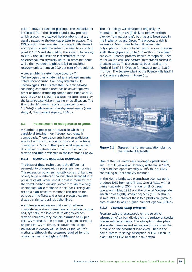
Environment Agency Guidance on gas treatment technologies for landfill gas engines 39
column (trays or random packing). The DEA solutionis released from the absorber under low pressure,which allows the dissolved hydrocarbons that areusually passed to the fuel gas system to escape. TheDEA solution is regenerated by contact with steam ina stripping column; the solvent is raised to its boilingpoint (110°C) and stripped by the steam. On coolingto 40°C, the DEA solution is recirculated to theabsorber column (typically up to 50 times per hour),while the hydrogen sulphide is fed to a sulphurrecovery unit to remove 99.9 per cent of the sulphur.
A wet scrubbing system developed by Q2
Technologies uses a patented amine-based materialcalled Enviro-Scrub®. Company literature (Q2
Technologies, 1993) states that the amine-basedscrubbing compound used has an advantage overother common scrubbing compounds (such as MEA,DEA, MDEA and NaOH) because the salts formed bythe latter release H2S on heating or acidification. TheEnviro-Scrub® system uses a triazine compound –1,3,5-tri(2-hydroxyethyl)-hexahydro-s-triazine (casestudy 4, Environment Agency, 2004d).
5.3 Pretreatment of halogenated organics
A number of processes are available which arecapable of treating most halogenated organiccompounds. These treatments have an additionaleffect of scrubbing carbon dioxide and other tracecomponents. Most of the operational experience todate has concentrated on the removal of carbondioxide and this is reflected in the information below.
5.3.1 Membrane separation techniques
The basis of these techniques is the differentialpermeability of gases within polymeric membranes.The separation polymers typically consist of bundlesof very large numbers of hollow fibres arranged in apressure vessel. When landfill gas is introduced intothe vessel, carbon dioxide passes through relativelyunhindered while methane is held back. This givesrise to a high-pressure, methane-rich gas on theoutside of the fibres and a lower pressure carbondioxide enriched gas inside the fibres.
A single-stage separation unit cannot achievecomplete separation of methane and carbon dioxideand, typically, the low-pressure off-gas (carbondioxide enriched) may contain as much as 12 percent v/v methane. The product gas contains around88 per cent v/v methane. However, multistageseparation processes can achieve 98 per cent v/vmethane, although the pressures required for thisoperation can be as high as 4 MPa.
The technology was developed originally byMonsanto in the USA (initially to remove carbondioxide from natural gas), but has also been used inthe Netherlands and Japan. The process, which isknown as ‘Prism’, uses hollow silicone-coatedpolysulphone fibres contained within a steel pressureshell. Throughputs of up to 100 m3/hour have beenachieved. Another process, known as ‘Separex’, usesspiral-wound cellulose acetate membranes packed inpressure tubes. This process has been used at thePortland landfill in Oregon for flows of up to 2,360m3/hour. The Separex plant at the Puente Hills landfillin California is shown in Figure 5.1.
Figure 5.1 Separex membrane separation plant at the Puente Hills landfill
One of the first membrane separation plants usedwith landfill gas was at Florence, Alabama; in 1983,this produced approximately 60 m3/hour of SNGcontaining 90 per cent v/v methane.
In the Netherlands, two plants have been set up toproduce SNG from landfill gas. One at Vasse with adesign capacity of 200 m3/hour of SNG beganoperation in May 1992 and the other at Weperpolder,which has a slightly smaller capacity (150 m3/hour),in mid-1993. Details of these two plants are given incase studies 10 and 11 (Environment Agency, 2004d).
5.3.2 Pressure swing processes
Pressure swing processes rely on the selectiveadsorption of carbon dioxide on the surface of specialporous solid adsorbents. The adsorption takes placeat elevated pressure and separation occurs when thepressure on the adsorbent is relieved – hence thename, ‘pressure swing’ adsorption or PSA. Clean-upplant utilising PSA operates in four steps:
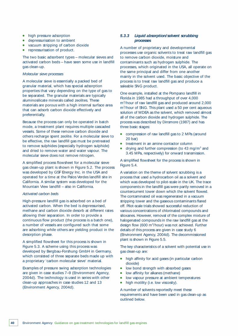
● high pressure adsorption● depressurisation to ambient● vacuum stripping of carbon dioxide● repressurisation of product.
The two basic adsorbent types – molecular sieves andactivated carbon beds – have seen some use in landfillgas clean-up.
Molecular sieve processes
A molecular sieve is essentially a packed bed ofgranular material, which has special adsorptionproperties that vary depending on the type of gas tobe separated. The granular materials are typicallyaluminosilicate minerals called zeolites. Thesematerials are porous with a high internal surface areathat can adsorb carbon dioxide effectively andpreferentially.
Because the process can only be operated in batchmode, a treatment plant requires multiple cascadedvessels. Some of these remove carbon dioxide andothers recharge spent zeolite. For a molecular sieve tobe effective, the raw landfill gas must be pretreatedto remove sulphides (especially hydrogen sulphide)and dried to remove water and water vapour. Themolecular sieve does not remove nitrogen.
A simplified process flowsheet for a molecular sievegas clean-up plant is shown in Figure 5.2. The processwas developed by GSF Energy Inc. in the USA andoperated for a time at the Palos Verdes landfill site inCalifornia. A similar system was developed for theMountain View landfill – also in California.
Activated carbon beds
High-pressure landfill gas is adsorbed on a bed ofactivated carbon. When the bed is depressurised,methane and carbon dioxide desorb at different ratesallowing their separation. In order to provide acontinuous flow product (the process is a batch one),a number of vessels are configured such that someare adsorbing while others are yielding product in thedesorption phase.
A simplified flowsheet for this process is shown inFigure 5.3. A scheme using this process wasdeveloped by Bergbau-Forshung GmbH in Germany,which consisted of three separate beds made up witha proprietary ‘carbon molecular sieve’ material.
Examples of pressure swing adsorption technologiesare given in case studies 7–9 (Environment Agency,2004d). The technology is used in series with otherclean-up approaches in case studies 12 and 13(Environment Agency, 2004d).
Environment Agency Guidance on gas treatment technologies for landfill gas engines40
5.3.3 Liquid absorption/solvent scrubbing processes
A number of proprietary and developmentalprocesses use organic solvents to treat raw landfill gasto remove carbon dioxide, moisture andcontaminants such as hydrogen sulphide. Theprocesses, which originated in the USA, all operate onthe same principal and differ from one anothermainly in the solvent used. The basic objective of theprocess is to treat raw landfill gas and produce asaleable SNG product.
One example, installed at the Pompano landfill inFlorida in 1985 had a throughput of over 4,000m3/hour of raw landfill gas and produced around 2,000m3/hour of SNG. This plant used a 50 per cent aqueoussolution of MDEA as the solvent, which removed almostall of the carbon dioxide and hydrogen sulphide. Theprocess was described by Dinsmore (1987) and hasthree basic stages:
● compression of raw landfill gas to 2 MPa (around 20 bar)
● treatment in an amine contactor column● drying and further compression (to 43 mg/m3 and
3.45 MPa, respectively) for onward transmission.
A simplified flowsheet for the process is shown in Figure 5.4.
A variation on the theme of solvent scrubbing is aprocess that used a hydrocarbon oil as a solvent andwhich was developed to pilot-scale in the UK. The tracecomponents in the landfill gas were partly removed in acountercurrent tower down which the solvent flowed.The contaminated oil was regenerated in a vacuumstripping tower and the gaseous contaminants flaredoff. Pilot-scale trials showed successful reduction ofvarious concentrations of chlorinated compounds andsiloxanes. However, removal of the complex mixture ofhalogenated compounds in the raw landfill gas at thedesign flow (600 m3/hour) was not achieved. Furtherdetails of this process are given in case study 6(Environment Agency, 2004d). The decommissionedplant is shown in Figure 5.5.
The key characteristics of a solvent with potential use ingas clean-up are:
● high affinity for acid gases (in particular carbon dioxide)
● low bond strength with absorbed gases● low affinity for alkanes (methane)● low vapour pressure at ambient temperatures● high motility (i.e. low viscosity).
A number of solvents reportedly meet theserequirements and have been used in gas clean-up asoutlined below.

Environment Agency Guidance on gas treatment technologies for landfill gas engines 41
Raw landfill gas
Condensate
Knockoutdrum
Compressor
CompressorSNG product
Dryer and H2S stripper
Regenerating sieves
Operating sieves
Siev
e 1
Siev
e 1
Siev
e 2
Siev
e 2
Siev
e 'n
'Si
eve
'n'
Figure 5.2 Simplified flowsheet for a molecular sieve gas clean-up plant
Raw landfill gas
Condensate
Regenerator gas heaterTreated gas
Condensate
Cooler
Recy
cled
/fue
l fee
d
Knockoutdrum
Compressor
Act
ive
and
rege
nera
ting
beds
Figure 5.3 Simplified flowsheet for a PSA plant using activated carbon beds
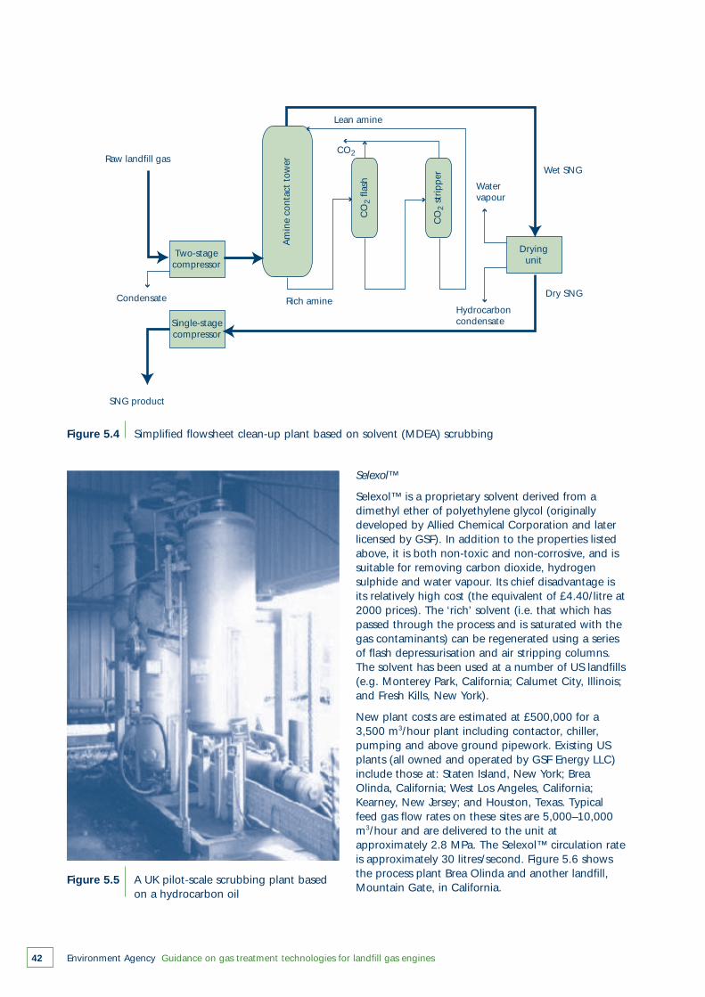
Environment Agency Guidance on gas treatment technologies for landfill gas engines42
Figure 5.4 Simplified flowsheet clean-up plant based on solvent (MDEA) scrubbing
Figure 5.5 A UK pilot-scale scrubbing plant based on a hydrocarbon oil
Raw landfill gas
SNG product
Condensate Rich amine
Lean amine
Water vapour
Hydrocarboncondensate
Dry SNG
Wet SNG
CO2
Two-stage compressor
Single-stagecompressor
Drying unit
Am
ine
cont
act
tow
er
CO
2 fla
sh
CO
2 st
ripp
er
Selexol™
Selexol™ is a proprietary solvent derived from adimethyl ether of polyethylene glycol (originallydeveloped by Allied Chemical Corporation and laterlicensed by GSF). In addition to the properties listedabove, it is both non-toxic and non-corrosive, and issuitable for removing carbon dioxide, hydrogensulphide and water vapour. Its chief disadvantage isits relatively high cost (the equivalent of £4.40/litre at2000 prices). The ‘rich’ solvent (i.e. that which haspassed through the process and is saturated with thegas contaminants) can be regenerated using a seriesof flash depressurisation and air stripping columns.The solvent has been used at a number of US landfills(e.g. Monterey Park, California; Calumet City, Illinois;and Fresh Kills, New York).
New plant costs are estimated at £500,000 for a3,500 m3/hour plant including contactor, chiller,pumping and above ground pipework. Existing USplants (all owned and operated by GSF Energy LLC)include those at: Staten Island, New York; BreaOlinda, California; West Los Angeles, California;Kearney, New Jersey; and Houston, Texas. Typicalfeed gas flow rates on these sites are 5,000–10,000m3/hour and are delivered to the unit atapproximately 2.8 MPa. The Selexol™ circulation rateis approximately 30 litres/second. Figure 5.6 showsthe process plant Brea Olinda and another landfill,Mountain Gate, in California.

Environment Agency Guidance on gas treatment technologies for landfill gas engines 43
Figure 5.6 Selexol™ plants at Brea Olinda and Mountain Gate landfills in California
Kryosol
The Kryosol process uses methanol pressurised to 2.8MPa and chilled to around –70°C, and can absorbcarbon dioxide, acid gases and water vapour. Typically,the process is split into two streams; in one, the gas isdehydrated and, in the other, carbon dioxide isremoved. The ‘rich’ solvent streams (i.e. those whichhave passed through the process and are saturated withthe gas contaminants) are regenerated by acombination of flash evaporation and light heating.
Urcarsol-CR (DEA)
This process was developed by the John Zink Companyand uses a proprietary solvent called Ucarsol-CR. As analternative, DEA can be used. Both solvents removecarbon dioxide. The process requires pretreatmentstages to remove moisture and other hydrocarbons by acombination of refrigeration and adsorption onactivated carbon. The system has been used at theScranton landfill, Pennsylvania.
MEA
Developed originally for processing natural gas byremoving carbon dioxide and hydrogen sulphide, theprocess uses an aqueous solution of MEA in apressurised scrubbing tower, followed by regenerationby flash evaporation and steam stripping. The processsuffers from a number of disadvantages – principally,the high rate of loss of MEA during regeneration, thehigh process thermal load and the formation ofbreakdown by-products. In addition, the ‘rich’ solvent(saturated with carbon dioxide) is extremely corrosive.Further details are given by Zimmerman et al. (1985)and Henrich (1983).
5.3.4 Water scrubbing processes
The basis of these processes is high-pressure scrubbingof the raw landfill gas with pressurised water. Thisremoves a significant proportion of the acid gascontaminants (including carbon dioxide), which can bereleased from the wash water in an air- or steam-stripping tower. The resulting ‘regenerated’ water canbe recirculated for further use.
The main disadvantage of water scrubbing is the verylarge power consumption associated with the pumpingand handling of the circulating flows. Without suchflows, the product yield would not have the requiredlow concentration of carbon dioxide. The process alsoremoves hydrogen sulphide. A simplified flowsheet forthis process is shown in Figure 5.7. The process featuresin case study 5 (Environment Agency, 2004d).
A proprietary process using water was developed byCentral Plants Inc. and called the Binax Process. Theproduct gas contains up to 98 per cent v/v methaneand less than 2 per cent v/v carbon dioxide. Plant sizesrange from 300 to 1,770 m3/hour.
A variation on water scrubbing, which could offer loweroperational costs for landfill gas clean-up, is scrubbingwith an aqueous solution of potassium carbonate – theso-called ‘hot carbonate’ process. This process has beenin existence for many years and was originallydeveloped for use in the treatment of ‘sour’ natural gas.The process is well suited to treatment of gases withmoderate concentrations of carbon dioxide and lowconcentrations of hydrogen sulphide.
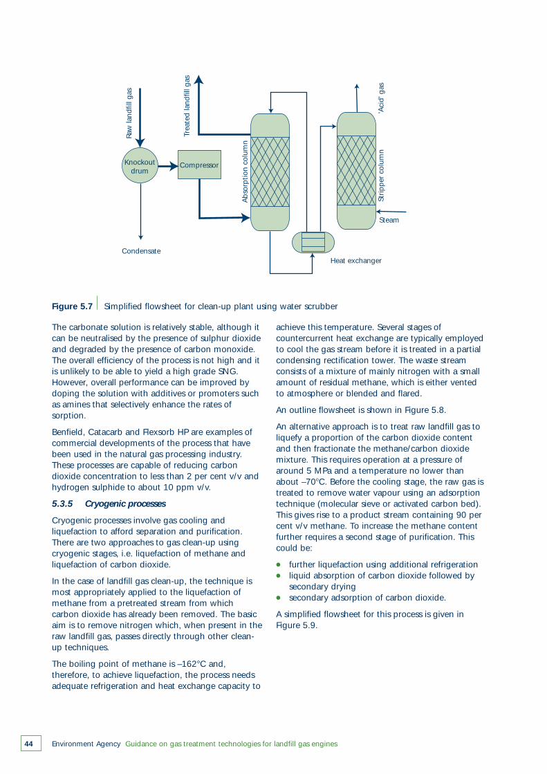
Environment Agency Guidance on gas treatment technologies for landfill gas engines44
Figure 5.7 Simplified flowsheet for clean-up plant using water scrubber
Raw
land
fill g
as
Trea
ted
land
fill g
as
Abs
orp
tion
colu
mn
Strip
per
col
umn
CondensateHeat exchanger
'Aci
d' g
as
Steam
Knockoutdrum
Compressor
The carbonate solution is relatively stable, although itcan be neutralised by the presence of sulphur dioxideand degraded by the presence of carbon monoxide.The overall efficiency of the process is not high and itis unlikely to be able to yield a high grade SNG.However, overall performance can be improved bydoping the solution with additives or promoters suchas amines that selectively enhance the rates ofsorption.
Benfield, Catacarb and Flexsorb HP are examples ofcommercial developments of the process that havebeen used in the natural gas processing industry.These processes are capable of reducing carbondioxide concentration to less than 2 per cent v/v andhydrogen sulphide to about 10 ppm v/v.
5.3.5 Cryogenic processes
Cryogenic processes involve gas cooling andliquefaction to afford separation and purification.There are two approaches to gas clean-up usingcryogenic stages, i.e. liquefaction of methane andliquefaction of carbon dioxide.
In the case of landfill gas clean-up, the technique ismost appropriately applied to the liquefaction ofmethane from a pretreated stream from whichcarbon dioxide has already been removed. The basicaim is to remove nitrogen which, when present in theraw landfill gas, passes directly through other clean-up techniques.
The boiling point of methane is –162°C and,therefore, to achieve liquefaction, the process needsadequate refrigeration and heat exchange capacity to
achieve this temperature. Several stages ofcountercurrent heat exchange are typically employedto cool the gas stream before it is treated in a partialcondensing rectification tower. The waste streamconsists of a mixture of mainly nitrogen with a smallamount of residual methane, which is either ventedto atmosphere or blended and flared.
An outline flowsheet is shown in Figure 5.8.
An alternative approach is to treat raw landfill gas toliquefy a proportion of the carbon dioxide contentand then fractionate the methane/carbon dioxidemixture. This requires operation at a pressure ofaround 5 MPa and a temperature no lower thanabout –70oC. Before the cooling stage, the raw gas istreated to remove water vapour using an adsorptiontechnique (molecular sieve or activated carbon bed).This gives rise to a product stream containing 90 percent v/v methane. To increase the methane contentfurther requires a second stage of purification. Thiscould be:
● further liquefaction using additional refrigeration● liquid absorption of carbon dioxide followed by
secondary drying● secondary adsorption of carbon dioxide.
A simplified flowsheet for this process is given inFigure 5.9.
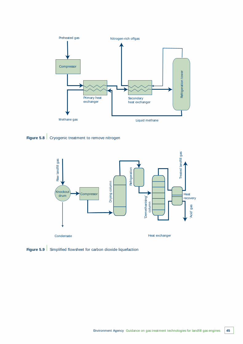
Condensate Heat exchanger
Heatrecovery
'Aci
d' g
asKnockout
drum
Raw
land
fill g
as
Dry
ing
colu
mn
Refr
iger
atio
n
Trea
ted
land
fill g
as
'Dem
etha
nisi
ng'
colu
mn
Compressor
Environment Agency Guidance on gas treatment technologies for landfill gas engines 45
Figure 5.8 Cryogenic treatment to remove nitrogen
Preheated gas
Primary heatexchanger
Secondaryheat exchanger
Methane gas Liquid methane
Nitrogen-rich offgas
Refr
iger
atio
n to
wer
Compressor
Figure 5.9 Simplified flowsheet for carbon dioxide liquefaction
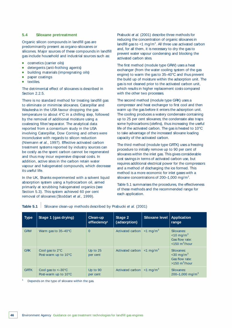
Environment Agency Guidance on gas treatment technologies for landfill gas engines46
5.4 Siloxane pretreatment
Organic silicon compounds in landfill gas arepredominantly present as organo-siloxanes orsilicones. Major sources of these compounds in landfillgas include household and industrial sources such as:
● cosmetics (carrier oils)● detergents (anti-frothing agents)● building materials (impregnating oils)● paper coatings● textiles.
The detrimental effect of siloxanes is described inSection 2.2.5.
There is no standard method for treating landfill gasto eliminate or minimise siloxanes. Caterpillar andWaukesha in the USA favour dropping the gastemperature to about 4°C in a chilling step, followedby the removal of additional moisture using acoalescing filter/separator. The analytical datareported from a consortium study in the USAinvolving Caterpillar, Dow Corning and others wereinconclusive with regards to silicon reduction(Niemann et al., 1997). Effective activated carbontreatment systems reported by industry sources canbe costly as the spent carbon cannot be regeneratedand thus may incur expensive disposal costs. Inaddition, active sites in the carbon retain watervapour and halogenated compounds, which decreaseits useful life.
In the UK, Shanks experimented with a solvent liquidabsorption system using a hydrocarbon oil, aimedprimarily at scrubbing halogenated organics (seeSection 5.3). This system achieved 60 per centremoval of siloxanes (Stoddart et al., 1999).
Prabucki et al. (2001) describe three methods forreducing the concentration of organic siloxanes inlandfill gas to <1 mg/m3. All three use activated carbonand, for all them, it is necessary to dry the gas toprevent water vapour condensing and blocking theactivated carbon sites.
The first method (module type GRW) uses a heatexchanger (from the water cooling system of the gasengine) to warm the gas to 35–40°C and thus preventthe build up of moisture within the adsorption unit. Thegas is not cleaned prior to the activated carbon unit,which results in higher replacement costs comparedwith the other two processes.
The second method (module type GRK) uses acompressor and heat exchanger to first cool and thenwarm up the gas before it enters the adsorption unit.The cooling produces a watery condensate containingup to 25 per cent siloxanes; the condensate also trapssome hydrocarbons (olefins), thus increasing the usefullife of the activated carbon. The gas is heated to 10°Cto take advantage of the increased siloxane loadingcapacity of the activated carbon.
The third method (module type GRTK) uses a freezingprocedure to initially remove up to 90 per cent ofsiloxanes within the inlet gas. This gives considerablecost savings in terms of activated carbon use, butrequires additional electrical power for the compressorsand a method of discharging the ice formed. Thismethod is a more economic for inlet gases with asiloxane concentrations of 200–1,000 mg/m3.
Table 5.1 summarises the procedures, the effectivenessof these methods and the recommended range foreach application.
Table 5.1 Siloxane clean-up methods described by Prabucki et al. (2001)
GRW Warm gas to 35–40°C 0 Activated carbon <1 mg/m3 Siloxanes:<10 mg/m3
Gas flow rate: <150 m3/hour
GRK Cool gas to 2°C Up to 25 Activated carbon <1 mg/m3 Siloxanes:Post-warm up to 10°C per cent <30 mg/m3
Gas flow rate: >150 m3/hour
GRTK Cool gas to <–30°C Up to 90 Activated carbon <1 mg/m3 Siloxanes:Post-warm up to 10°C per cent 200–1,000 mg/m3
Type Stage 1 (gas drying) Clean-up Stage 2 Siloxane level Applicationeffieciency1 (adsorption) range
1 Depends on the type of siloxane within the gas.
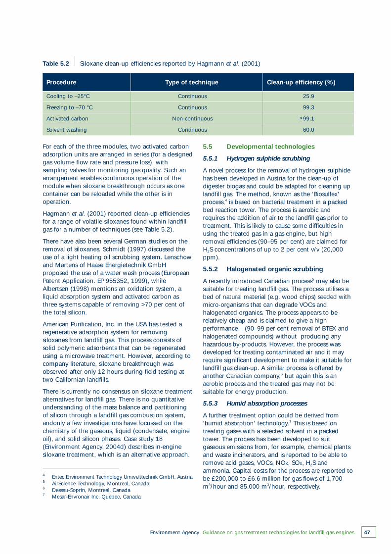
Environment Agency Guidance on gas treatment technologies for landfill gas engines 47
4 Entec Environment Technology Umwelttechnik GmbH, Austria5 AirScience Technology, Montreal, Canada6 Dessau-Soprin, Montreal, Canada7 Mesar-Envronair Inc. Quebec, Canada
Table 5.2 Siloxane clean-up efficiencies reported by Hagmann et al. (2001)
Cooling to –25°C Continuous 25.9
Freezing to –70 °C Continuous 99.3
Activated carbon Non-continuous 99.1
Solvent washing Continuous 60.0
Procedure Type of technique Clean-up efficiency (%)
For each of the three modules, two activated carbonadsorption units are arranged in series (for a designedgas volume flow rate and pressure loss), withsampling valves for monitoring gas quality. Such anarrangement enables continuous operation of themodule when siloxane breakthrough occurs as onecontainer can be reloaded while the other is inoperation.
Hagmann et al. (2001) reported clean-up efficienciesfor a range of volatile siloxanes found within landfillgas for a number of techniques (see Table 5.2).
There have also been several German studies on theremoval of siloxanes. Schmidt (1997) discussed theuse of a light heating oil scrubbing system. Lenschowand Martens of Haase Energietechnik GmbHproposed the use of a water wash process (EuropeanPatent Application. EP 955352, 1999), whileAlbertsen (1998) mentions an oxidation system, aliquid absorption system and activated carbon asthree systems capable of removing >70 per cent ofthe total silicon.
American Purification, Inc. in the USA has tested aregenerative adsorption system for removingsiloxanes from landfill gas. This process consists ofsolid polymeric adsorbents that can be regeneratedusing a microwave treatment. However, according tocompany literature, siloxane breakthrough wasobserved after only 12 hours during field testing attwo Californian landfills.
There is currently no consensus on siloxane treatmentalternatives for landfill gas. There is no quantitativeunderstanding of the mass balance and partitioningof silicon through a landfill gas combustion system,andonly a few investigations have focussed on thechemistry of the gaseous, liquid (condensate, engineoil), and solid silicon phases. Case study 18(Environment Agency, 2004d) describes in-enginesiloxane treatment, which is an alternative approach.
5.5 Developmental technologies
5.5.1 Hydrogen sulphide scrubbing
A novel process for the removal of hydrogen sulphidehas been developed in Austria for the clean-up ofdigester biogas and could be adapted for cleaning uplandfill gas. The method, known as the ‘Biosulfex’process,4 is based on bacterial treatment in a packedbed reaction tower. The process is aerobic andrequires the addition of air to the landfill gas prior totreatment. This is likely to cause some difficulties inusing the treated gas in a gas engine, but highremoval efficiencies (90–95 per cent) are claimed forH2S concentrations of up to 2 per cent v/v (20,000ppm).
5.5.2 Halogenated organic scrubbing
A recently introduced Canadian process5 may also besuitable for treating landfill gas. The process utilises abed of natural material (e.g. wood chips) seeded withmicro-organisms that can degrade VOCs andhalogenated organics. The process appears to berelatively cheap and is claimed to give a highperformance – (90–99 per cent removal of BTEX andhalogenated compounds) without producing anyhazardous by-products. However, the process wasdeveloped for treating contaminated air and it mayrequire significant development to make it suitable forlandfill gas clean-up. A similar process is offered byanother Canadian company,6 but again this is anaerobic process and the treated gas may not besuitable for energy production.
5.5.3 Humid absorption processes
A further treatment option could be derived from‘humid absorption’ technology.7 This is based ontreating gases with a selected solvent in a packedtower. The process has been developed to suitgaseous emissions from, for example, chemical plantsand waste incinerators, and is reported to be able toremove acid gases, VOCs, NOx, SOx, H2S andammonia. Capital costs for the process are reported tobe £200,000 to £6.6 million for gas flows of 1,700m3/hour and 85,000 m3/hour, respectively.
>
Environment Agency Guidance on gas treatment technologies for landfill gas engines48
5.6 Dealing with wastes from secondary clean-up processes
Wastes from secondary pretreatment can be groupedinto three categories:
● contaminated carbon dioxide off-gas● contaminated aqueous condensates● contaminated solids.
5.6.1 Contaminated carbon dioxide off-gas
Off-gas streams represent the largest arising and canamount to up to 5,000 tonnes/year of carbon dioxideand up to 1,000 tonnes/year of nitrogen for every1,000 m3/hour of raw landfill gas processed.
Since the off-gas stream also contains some methane(5–10 per cent v/v), the usual approach to treatmentwould be to flare the stream blended with aproportion of raw landfill gas. However, early processplant – especially those producing high grade SNG(methane ~98 per cent v/v) – often vented the off-gas direct to atmosphere.
5.6.2 Contaminated aqueous condensates
The aqueous condensates arise in varying, althoughgenerally small rates, and have historically beendrained and returned direct to the landfill/treatmentplant.
Condensates may also arise which are contaminatedwith process solvents and these may requirespecialised treatment or disposal.
Such streams are unlikely to be more than ‘a fewtonnes’ per year because the process will be designedto minimise the loss of relatively costly solvents.
The sulphur and chlorine removed should not bereturned to the landfill where they will re-enter thegas management system. Best practice is to treat suchcondensates or destroy them either chemically or byincineration
5.6.3 Contaminated solids
Contaminated solid wastes will consist of numerousmaterials, depending on the type of clean-up process.For example, PSA plant will produce batches of‘spent’ adsorbent (around 5–10 tonnes/year), whichare likely to be ‘regenerated’ to recover theadsorbent. Wastes that arise within the ‘regeneration’part of the process are usually disposed of via hightemperature incineration.
Other forms of solid wastes include:
● spent oxides (from desulphurising units) of around5–10 tonnes/year, which can be regenerated;
● filter pads and meshes;● other maintenance consumables.
Environment Agency Guidance on gas treatment technologies for landfill gas engines 49
6
Engine management, in-engine andexhaust treatment6.1 Introduction
Secondary pretreatment of landfill gas can be anexpensive option. However, many enginemanagement, in-engine and post combustion(exhaust) treatments are available at a much lowercapital and operational cost, and it is likely that thesetechnologies will dominate future solutions toemissions management.
Engine management systems and in-enginetreatments can be used to reduce NOx and siloxanes,while post-combustion systems can be used for NOx,CO, aldehydes, and acid halides.
6.2 Gas engines and their operation
When considering engine management, it is firstnecessary to understand the operation of the gasengine.
The two principal methods used to ignite the gas andair mixture in the combustion chamber of areciprocating engine are:
● injection of a small quantity of diesel fuel (dual-fuel engines)
● use of a high voltage spark (spark ignition engines).
More than 98 per cent of engines used for powergeneration from landfill gas are of the spark ignitiontype. This is partly due to the ready availability ofnominal 1 MWe output generating sets, whichhappen to be especially suitable for the quantity ofgas available from most UK landfill sites. Sparkignition engines also have a simpler construction anddo not incur the added cost of diesel fuel or its on-site handling.
Gas turbines are in use but are not currentlyconsidered a realistic option for power generationfrom landfill gas. This is because there is virtually nocommercially viable applications for the significantwaste exhaust heat that results from their lowerthermal efficiency (25–28 per cent in a gas turbinecompared with 38–42 per cent in a spark ignition
engine). Further barriers to their selection includedifficulties in compressing the gas to the requiredpressure (owing to condensation and corrosion),damage to turbine blades from siloxanes or corrosion,and the fact that such units tend to be at least 3 MWe
capacity,. Small microturbine units (100 kWe) havebeen used in the USA and are currently being testedat least one UK landfill site. However, a fulltechnological-economic evaluation based on whole-life cost is needed before plant operators are likely toconsider the general use of such units.
Setting aside fuel constituents, engine speed, borediameter and piston stroke are the design featuresinfluencing the power output, efficiency and exhaustgas emissions from an engine.
The detailed design of combustion chamber relatedcomponents (including cylinder heads, liners andvalves) have a secondary influence. All such designaspects are addressed when an engine type receivescertification to a defined emission standard such as inthe German TA Luft approach. Once in productionand with large numbers of a particular engine type inservice, variation of the design to improve emissionlevels is not normally an option.
The most common variation in design is the choice ofeither a ‘wet’ or a ‘dry’ exhaust manifold. Use of ‘wet’(water-cooled) exhaust manifolds removes energyfrom the exhaust gases that, in turn, reduces thepower of the turbocharger (which compresses theengine inlet air). The result is a less thermally efficientengine, lower output and lower NOx.
Any reduction in thermal efficiency imposes penaltiesin the form of a higher capital cost per kWe installedand lost revenue. For example, a 5 per cent reductionin output for a plant earning 3 pence per unitequates to a nominal loss of £12,000/year.
When considering adopting a clean-up technology,an operator’s main concerns are related to the need(engine longevity and environmental impact) andoverall cost, which determine the commercial viabilityof the project for electrical power generation.
Four key areas are addressed when considering theoptimum balance between engine thermal efficiency,longevity and exhaust emissions:
● electronic engine management systems● in-engine treatment at pre-combustion or postcombustion stages● exhaust gas after-treatment● supply gas clean-up (see Sections 4 and 5).
6.3 Engine management systems and NOx
The combustion process in a modern gas engine iscontrolled and balanced by the electronic enginemanagement system (EMS). Continuous, computer-controlled adjustment of parameters such as engineignition timing, airflow from the turbocharger andcooling water temperature is available on all moderngas engines fitted at key locations with analogue ordigital transducers. Sampling of parameters usuallyoccurs once every 50 milliseconds. The capability ofthese systems has improved steadily and furtheradvances are anticipated.
The complete EMS system is designed as anintegrated suite of panels including:
● control of ancillary motors● synchronising to the external electrical network● pre-detonation adjustment● telemetry functions for remote monitoring, control
and recording.
These functions are not relevant to this guidance andare not considered here.
The operator interface is usually driven via a fascia-mounted touch screen with full graphicrepresentation of the system. Faults, real time valuesand historic data can all be displayed. Such as systemis described as a supervisory control and dataacquisition (SCADA) system. Examples includeCaterpillar’s Lima, Deutz’s Tem and the JenbacherDiane systems. These names should not be confusedwith major system components such as the air to fuelcontroller (e.g. Caterpillar’s Techjet).
The operating conditions chosen on the EMS mustachieve the balance between greater thermalefficiency (which brings with it high NOx), and thelean-burn condition with better destruction of VOCsand lower NOx. Most gas engines are operated inlean-burn mode.
Users can set the EMS of a typical 1 MWe sparkignition engine to operate at 500 mg/Nm3 NOx
rather than the normal value used in the UK of 650mg/Nm3. This is a cost-effective way of reducing NOx
emissions and this practice is recommended.
Environment Agency Guidance on gas treatment technologies for landfill gas engines50
Reducing NOx emissions below this level can createother operational problems and should not beencouraged.
A setting of 500 mg/Nm3 NOx will result in higherCO emissions than one of 650 mg/Nm3 NOx. Thesegases tend to exhibit an antithetic relationship and itis important to achieve a balance between the twoemissions. It is preferable to hold NOx at 500mg/Nm3 and allow CO emissions to rise because NOx
is usually the emission that requires primary control.CO will oxidise to CO2, although care should betaken with high CO emissions in enclosed areas.
6.4 In-engine treatments
Various in-engine treatments are described belowtogether with examples of available and emergingtechnologies. Some or all of these may help operatorsof landfill gas utilisation plant to meet emissionstandards and to increase engine longevity. Costbenefit analysis (see Section 3) will help to identifythe potential cost-effectiveness for these treatmentoptions.
The application of in-engine treatments may increasecapital or running costs; for example, the need foradditional specialist equipment and water purificationplant. In addition, a simple water mist and/orchemicals have varying degrees of success dependingon the aggressiveness of the supply gas. Site-specifictrials are therefore recommended before full-scaleapplication.
6.4.1 Water injection to reduce NOx
Humidification or injection of de-ionised water (whichquickly becomes steam) into the engine beforecombustion is a proven technology used extensivelyto reduce NOx in large industrial and marine dieselengines. The technique has been tried with someencouraging results on landfill gas engines. Wherethere is a need to reduce NOx while retaining goodthermal efficiency, it may attract greater interest. Testswith the Biometer system showed a 50 per centreduction in NOx (see case study 17, EnvironmentAgency, 2004d).
Provided the system is properly controlled (to preventdamage to other engine components), it has thepotential advantage of preventing the build-up ofcombustion deposits (and silica from siloxanes), andthus extending the time between maintenance. Goodcontrol is essential as a moist atmosphere combinedwith the hydrogen chloride and hydrogen fluorideproduced from halogenated organic compounds inthe supply gas may lead to a rapid deterioration ofengine components. Rusting of components, owing
Environment Agency Guidance on gas treatment technologies for landfill gas engines 51
to residual free water, when the engine is shutdown isalso a possibility.
Water mist injection is used extensively to reduce NOx
in reciprocating engines outside the landfill gasindustry; reduced build-up of combustion deposits isa secondary advantage. Many of these engines have asecond injector that sits alongside the fuel injector forthis purpose.
Because NOx reduction has not previously beennecessary,# there has been no uptake of thistechnology within the landfill gas industry. De-ratingof the engine is the only other known practicaloption. Conventional NOx abatement as part of anexhaust after-treatment has not been commerciallyviable owing to poisoning of the catalyst.
Capital costs are likely to be low if ‘humidificationkits’ are produced in quantity, although the finebalance currently achieved with lubricating oilformulation and other material influences would needto be addressed.
6.4.2 Oxygen enrichment
Increasing the oxygen content of the engine inlet airby a few percent – with associated engine tuning –can enable liquid and gaseous fuels to burn moreefficiently. Although this has been known for decades,it has not been commercially viable owing to therelatively high cost of commercially produced oxygenand the additional care required for storage. Thepurchase of liquid oxygen and an associated vaporisermay not be commercially viable owing to thesignificant quantity of oxygen required.
In recent years, development of liquid fuel engineshas enabled adequate air inlet enhancement with useof patented technology resulting in a nominal 3 x 3x 3 metre ‘air inlet filter’ for a 1 MWe engine.Refinement is expected to allow smaller unit sizes,although most industrial installations canaccommodate the additional space required. Thistechnology has been used successfully on plantoutside the landfill gas utilisation industry.
If this developing technology was implemented,methane slippage (which could account for 98 per centof the VOCs in the exhaust) could be reduced and COlevels might fall dramatically. A reduction in the peakcylinder pressure also helps to reduce the onset of pre-ignition (knock) and, therefore, a higher output may beanticipated.
The disadvantage of oxygen enrichment is the highlevels of NOx generated (a direct result of higher peakcombustion temperatures). Subsequent after-treatmentof NOx to achieve acceptable emissions is unlikely to becommercially viable.
Capital costs are likely to be relatively low providedlarge numbers of air inlet ‘kits’ are produced.
6.4.3 Exhaust gas recirculation
Recirculating inert exhaust gas reduces the peakcombustion temperature and engine efficiency. It is notcurrently used on landfill gas engines, but a 10–50 percent NOx reduction might be anticipated at minimalcost – with the added likely benefit of reduced methaneslippage. However, further attention needs to be givento the quantity of power loss involved and the extent ofaccelerated engine deterioration as a result ofrecirculating aggressive gas constituents.
6.4.4 Chemical injection
The presence of siloxanes in the supply gas can have asimilar affect as the presence of acid forming gases interms of engine wear. In this case, however, keepingengine operating temperatures well above dew pointsdoes not help.
Trials have involved injecting a chemical formulation viastainless steel nozzles located within the air inletmanifold. An automated dosing unit is programmed forfrequency of application and spray duration to treat theparticular characteristics of the contaminant, engineand operating environment. The cleaning fluid reacts torelease a fine dry powder that travels through theengine and passes out with the exhaust gases. Thebalance of effects has been shown to provide asignificant overall improvement in the life of enginecomponents.
By the end of 2001, trials had been carried out at sixlandfill site installations. The trials are claimed to showthat siloxane build-up in a 1 MWe engine can bemanaged effectively using a total of 1.5–2 litres of fluidper day administered in six doses. Figure 6.1 showsfront exhaust valves and valve seats for both treatedand untreated engines.
For a 1 MWe engine, the capital cost is approximately£5,500 and the running costs £5 per litre (see casestudy 18, Environment Agency, 2004d).
Experience suggests that, for landfill gas engines (andengines burning other fuels), the build-up of depositscan be achieved either by injecting a water-mist or byinjecting chemicals in association with a water mist. This‘in-engine clean-up’ helps to prevent deposit build-upon combustion chamber surfaces, exhaust valves andthe turbocharger. The deposits are not, at this stage, ofsignificant size and no engine components downstreamof the turbocharger would be affected. However, if thismethod were used after significant deposits had builtup, then such deposits could cause problems on exit,especially if they became entrapped between theexhaust valve and cylinder head seat.
# Table 2.3 lists the generic emission standards set by the regulators
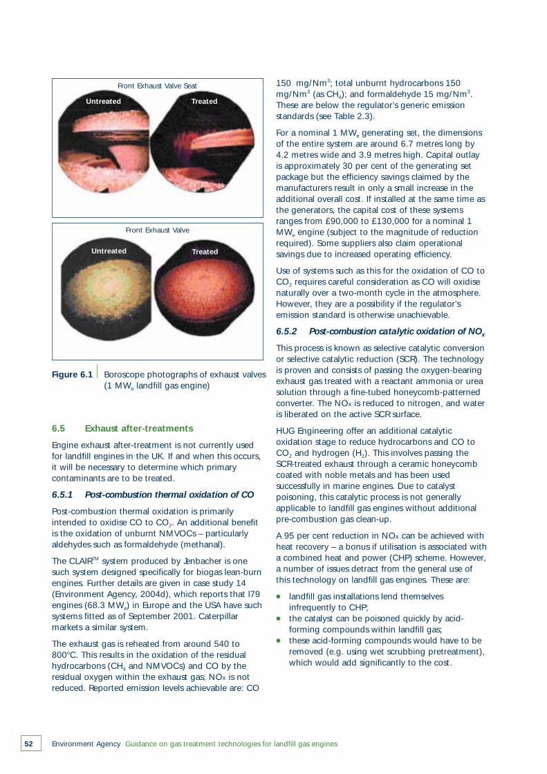
Environment Agency Guidance on gas treatment technologies for landfill gas engines52
Figure 6.1 Boroscope photographs of exhaust valves(1 MWe landfill gas engine)
6.5 Exhaust after-treatments
Engine exhaust after-treatment is not currently usedfor landfill engines in the UK. If and when this occurs,it will be necessary to determine which primarycontaminants are to be treated.
6.5.1 Post-combustion thermal oxidation of CO
Post-combustion thermal oxidation is primarilyintended to oxidise CO to CO2. An additional benefitis the oxidation of unburnt NMVOCs – particularlyaldehydes such as formaldehyde (methanal).
The CLAIRTM system produced by Jenbacher is onesuch system designed specifically for biogas lean-burnengines. Further details are given in case study 14(Environment Agency, 2004d), which reports that l79engines (68.3 MWe) in Europe and the USA have suchsystems fitted as of September 2001. Caterpillarmarkets a similar system.
The exhaust gas is reheated from around 540 to800oC. This results in the oxidation of the residualhydrocarbons (CH4 and NMVOCs) and CO by theresidual oxygen within the exhaust gas; NOx is notreduced. Reported emission levels achievable are: CO
150 mg/Nm3; total unburnt hydrocarbons 150mg/Nm3 (as CH4); and formaldehyde 15 mg/Nm3.These are below the regulator’s generic emissionstandards (see Table 2.3).
For a nominal 1 MWe generating set, the dimensionsof the entire system are around 6.7 metres long by4.2 metres wide and 3.9 metres high. Capital outlayis approximately 30 per cent of the generating setpackage but the efficiency savings claimed by themanufacturers result in only a small increase in theadditional overall cost. If installed at the same time asthe generators, the capital cost of these systemsranges from £90,000 to £130,000 for a nominal 1MWe engine (subject to the magnitude of reductionrequired). Some suppliers also claim operationalsavings due to increased operating efficiency.
Use of systems such as this for the oxidation of CO toCO2 requires careful consideration as CO will oxidisenaturally over a two-month cycle in the atmosphere.However, they are a possibility if the regulator’semission standard is otherwise unachievable.
6.5.2 Post-combustion catalytic oxidation of NOx
This process is known as selective catalytic conversionor selective catalytic reduction (SCR). The technologyis proven and consists of passing the oxygen-bearingexhaust gas treated with a reactant ammonia or ureasolution through a fine-tubed honeycomb-patternedconverter. The NOx is reduced to nitrogen, and wateris liberated on the active SCR surface.
HUG Engineering offer an additional catalyticoxidation stage to reduce hydrocarbons and CO toCO2 and hydrogen (H2). This involves passing theSCR-treated exhaust through a ceramic honeycombcoated with noble metals and has been usedsuccessfully in marine engines. Due to catalystpoisoning, this catalytic process is not generallyapplicable to landfill gas engines without additionalpre-combustion gas clean-up.
A 95 per cent reduction in NOx can be achieved withheat recovery – a bonus if utilisation is associated witha combined heat and power (CHP) scheme. However,a number of issues detract from the general use ofthis technology on landfill gas engines. These are:
● landfill gas installations lend themselves infrequently to CHP;
● the catalyst can be poisoned quickly by acid-forming compounds within landfill gas;
● these acid-forming compounds would have to be removed (e.g. using wet scrubbing pretreatment),which would add significantly to the cost.
Front Exhaust Valve Seat
Front Exhaust Valve
Untreated
Untreated
Treated
Treated
Environment Agency Guidance on gas treatment technologies for landfill gas engines 53
6.5.3 Halide scrubbing
On some landfills with very high chloride loadingsand without pre-combustion gas clean-up, emissionsof HCl and HF may need to be reduced to meet thestandards set in the site-specific risk assessment. Theabsorption modular system described in case studies15 and 16 (Environment Agency, 2004d) has thepotential for application to clean-up of HCl and HFemissions from landfill gas engine exhausts, but thetechnology has not yet been applied to landfill gasengines.
This system is claimed to reduce such emissions tobelow TA Luft standards from even the highestobserved concentrations of these components inexhaust gases. The exhaust gas containing the halidesflows through a reactor containing calcium hydroxidebonded to a honeycomb that provides a largecontact surface area. The waste produced is a mixtureof calcium chloride and calcium fluoride, and residualcalcium hydroxide. A standard unit is capable oftreating exhaust flow rates of 9,000–10,000Nm3/hour. The replacement rate for the molecularmonolith blocks depends on the inlet loading of HCland HF in the exhaust.
Environment Agency Guidance on gas treatment technologies for landfill gas engines54
Conclusions
7
The treatment of landfill gas used in powergeneration has both financial and environmentalimplications. A cost benefit analysis should beconducted on the cost and environmental factors thatwill arise from employing a particular treatment onthe supply gas to or emissions from the engine.Although financial issues such as reducingmaintenance costs and economic viability of theutilisation scheme will be of concern to operators andpower producers, the principal concern of theregulator is the cost benefit balance on environmentalfactors. This guidance gives benchmark figures toenable a judgement as to whether the cost ofabatement of a particular emission will be beneficial.
Primary pretreatment of the supply gas to removeparticles, liquids and vapours enhances theperformance of the landfill gas engines and normallygives significant financial benefits to the operator interms of reduced wear on the engine and betteroverall performance. The environmental costs aregenerally low and there will be some environmentalbenefits. Thus, one or more methods for the primarypretreatment of landfill gas are typically installed.
Secondary pretreatment to remove chemicalcomponents in the supply gas incurs substantial costsand will involve some environmental cost, particularlyin the management of the secondary waste arisings.A careful assessment of the costs and benefits mustbe conducted following the procedure recommendedin this guidance in order to clarify the financial andenvironmental impact of a particular treatmentrelative to the status quo.
In-engine and post-combustion emissions treatmentremoves some of the bulk (and trace) gas products ofcombustion that can affect air quality. The cost ofthese processes should be considered in terms ofboth the capital cost of the equipment and thereduced power output that normally accompaniessuch methods. The environmental costs are generallylow and the environmental benefits may besignificant for some gas streams at particularlysensitive locations. A site-specific cost-benefit analysisis necessary to determine whether in-enginetreatment is justified. This should follow thesystematic CBA procedure recommended in this
guidance to provide an auditable and common basisfor comparison.
The benchmark figures for the introduction of aparticular abatement technology require low processcosts to warrant treatment for reducing CH4 and COemissions. Intermediate process costs will justifytreatment to reduce NOx emissions, but much highercost processes are justified to abate elevated PM10 andNMVOC emissions.
The average landfill gas engine operator is currentlymost likely to have to decide on an economic balancebetween reducing the engine efficiency to reduceNOx while accepting an increase in CO and VOCemissions so as to operate within exhaust emissionlimits. If it is not going to be possible to achieve theselimits, then modest use of some of the technologiesoutlined (including secondary combustion of theexhaust gas) may be necessary.
Owing to an aggressive supply gas, a minority oflandfill gas engines will experience difficulties that willresult in the need for one or more of the specialisedtechnologies described in this guidance.
Environment Agency Guidance on gas treatment technologies for landfill gas engines 55
Glossary and acronyms1 MWe
1 megawatt electrical output – the nominal output ofmost internal combustion spark ignition gas enginesused in the landfill gas industry today. Approximately3 MW of thermal input is required to produce 1 MWof electrical output.
abatementReducing the degree or intensity of, or eliminating,pollution.
absorptionRemoval of a pollutant from a liquid or gaseoussupply by the uptake and retention of the pollutantinto a solid or liquid.
acidificationContinuing loss of capacity to neutralise acid inputsindicated by declining alkalinity and increasinghydrogen ion concentration (i.e. the decrease in pHof a solution resulting from increases in acidic anioninputs such as sulphate).
activated carbonA highly adsorbent form of carbon used to removeodours and toxic substances from a liquid or gaseoussupply.
adsorptionRemoval of a pollutant from a liquid or gaseoussupply by collecting the pollutant on the surface of asolid material.
aerobicIn the presence of oxygen.
after-burnerA burner located such that the combustion gases aremade to pass through its flame in order to removeparticulates, unburnt hydrocarbons and odours.
after-coolingTreatment process to separate and remove watervapour and liquids from a compressed gas supply toprevent condensation downstream.
alkalineThe condition of the gaseous or liquid supply whichcontains a sufficient amount of alkali substance toraise the pH above 7.0.
alkalinityThe capacity of bases to neutralize acids, e.g. theaddition of lime decreases acidity.
alkanesA group of straight chain, saturated hydrocarbonscontaining no double or triple bonds. Includesmethane.
alkenesA class of unsaturated aliphatic hydrocarbons havingone or more double bonds.
anaerobicIn the absence of oxygen.
back-pressureA pressure that can cause gas or liquid to backflowinto the upstream inlet gas or liquid supply if thesystem is at a higher pressure than that upstream.
BATbest available techniques
BTEXBenzene, toluene, ethylbenzene and xylene. Thesevolatile monoaromatic hydrocarbons are commonlyfound together in crude petroleum and petroleumproducts such as gasoline.
biodegradationBreakdown by micro-organisms.
biogasA methane-based fuel produced through thebiodigestion of organic material.
biomassTerm used to refer to the mass of biologically activematerial contained in a reactor such as a landfill.
BODBiochemical oxygen demand.
boroscopeA long thin rod-like device providing visual accessinto inaccessible areas (such as engine combustionchambers). It uses a long narrow tube containing ahigh intensity light source and high definition opticssystem, which can be connected to camera systemsfor obtaining images.
C&DConstruction and demolition.
capital costsCosts assigned to the setting up (commissioning),design, and construction of a plant for clean-upoperations.
catalystA substance that changes the speed or yield of achemical reaction without being consumed orchemically changed by the chemical reaction.
catalytic oxidation(1) An oxidation process that is speeded up by the
presence of a substance that is itself notconsumed in the reaction.
(2) Method of measurement for flammable gas:portable detectors measure the difference inresistance of two pellistors, one control and onethat lies in a sample chamber. Flammable gaswithin the sample being monitored will oxidiseclose to the surface of the pellistor, changing itstemperature and resistance; the amount oftemperature change is proportional to the amountof flammable gas in the sample.
(3) A method for post-combustion gas clean-up(usually for CO and unburnt hydrocarbons), butnot normally used on landfill gas engines since themany other components in landfill gas can poisonthe catalyst, rendering the clean-up techniqueineffective.
causticAny strongly alkaline material that has a corrosive orirritating effect on living tissue, e.g. caustic soda(NaOH).
CBACost benefit analysis
CFCChlorofluorocarbon
CFC-11Trichlorofluoromethane
CFC-12Dichlorodifluoromethane
CH4
Methane
chillerA device that generates a cold liquid that is circulatedthrough an air-handling unit’s cooling coil to cool agas supply, used to dewater inlet supply gas.
chlorinated solventAn organic solvent containing chlorine atoms (e.g.methylene chloride or 1,1,1-trichloromethane).
CHPCombined heat and power
clean-up efficiencyThe quantity of the contaminant removed from thegas inlet due to the clean-up process relative to thequantity within the gas inlet. Usually expressed as apercentage.
Environment Agency Guidance on gas treatment technologies for landfill gas engines56
COCarbon monoxide
CO2
Carbon dioxide
CODChemical oxygen demand
combustionBurning or rapid oxidation of a gas accompanied bythe release of energy in the form of heat and light,producing carbon dioxide and water. Incompletecombustion will also produce intermediate andunburnt hydrocarbons, as well as carbon monoxide.
condensateLiquid formed when warm landfill gas cools as ittravels through a collection or clean-up system. Madeup of mostly water with some trace hydrocarbonspresent.
condensationThe change of state of a substance from the vapourto the liquid (or solid) form. Also a type of chemicalreaction in which two or more molecules combinewith the separation of water, alcohol, or other simplesubstance.
corrosionThe electrochemical degradation of metals or alloyscaused by reaction with their environment. Isaccelerated by the presence of acids or bases.
CVCalorific value
cycloneA device that uses centrifugal force to remove largeparticles from a gas stream.
cylinderThe round hole in the engine block in which thepiston(s) ride.
cylinder blockThe main structural member of an engine in which isfound the cylinders, crankshaft and other principalparts.
cylinder headThe detachable portion of the engine, usuallyfastened to the top of the cylinder block andcontaining all or most of the combustion chambers.
DCFDiscounted cash flow
DEADiethanolamine
Environment Agency Guidance on gas treatment technologies for landfill gas engines 57
decompositionNatural breakdown of organic materials by the actionof micro-organisms, a chemical reaction or physicalprocesses.
degradationSee decomposition.
demineralising (de-ionising)A method of purifying water that first converts solublesalts into acids by passing through a hydrogenexchanger and then removes them by an acidadsorbent or synthetic resin.
demisterUses a fine spray or aerosol to separate outcontaminants from cooled gas, which can then bedischarged.
desorptionThe process of removing an adsorbed material fromthe solid on which it is adsorbed. Accomplished byheating, reduction of pressure, the presence ofanother more strongly adsorbed substance or acombination of these means.
desulphurisationRemoval of sulphur from a gaseous fuel supply bymeans of wet or dry scrubbing.
detonationThe extremely rapid, self-propagating decompositionof an explosion accompanied by a high-pressure-temperature wave moving at 1,000–9,000metres/second.
diethyl sulphideChemical added to mains gas to give it an odour.Also found in landfill gas.
digesterA closed tank or unit in which bacterial action isinduced and accelerated in order to break downorganic matter and establish the proper carbon tonitrogen ratio.
dryingThe process of reducing or removing moisture fromthe gas supply.
EALEnvironmental Assessment Level
emissionA material that is expelled or released to theenvironment. Usually applied to gaseous or odorousdischarges to atmosphere.
EMSEngine management system
environmental impactThe total effect of any operation on the environment
exhaust manifoldThat part of the exhaust system which carries theexhaust gases from cylinders to the exhaust pipe.
exhaust valveDevice used to discharge the burnt gases from thecombustion chambers.
filtrationA treatment process for removing solid (particulate)matter from gases or liquids by means of porousmedia.
flammableA substance supporting combustion in air.
flue gasExhaust gas coming out of a chimney or stack aftercombustion in the burner it is venting. Can includenitrogen oxides, carbon oxides, water vapour, sulphuroxides, particles and many trace pollutants
gas aggressiveness indexAn index commonly used to indicate the degree ofacidic components (Cl and F) of the landfill gas for asite, determined as ,
where total Cl and total F are the chlorine andfluorine concentrations (mg/m3) and CH4% is themethane concentration (% v/v) of the inlet gas
gas chromatographyAnalytical method that utilises a gaseous mobilephase with either a liquid (GLC) or solid stationary(GSC) phase.
HClHydrogen chloride/hydrochloric acid (when damp)
headPressure often used in the context of pressure exertedby a standing fluid, usually water.
heat exchangerA reaction chamber in which the flow of hot exhaustgases can be reversed via a switching unit in order tominimise heat losses and energy requirements.
HFHydrogen fluoride/hydrofluoric acid (when damp)
honeycombStructure or supported network within a container,providing a large surface area of a compoundensuring even flow of the process gas with which itinteracts to remove specific contaminants.
(total Cl + 2 total F)100%
CH4%
hydrocarbonA chemical compound containing hydrogen andcarbon.
hydrogen sulphide (H2S)Gas emitted during organic decomposition, with anodour of rotten eggs and which, in highconcentrations, can kill or poison.
ignitableCapable of burning or causing a fire.
In situIn its original place, remaining at the site or in thesubsurface.
IPPCIntegrated Pollution Prevention and Control
landfill gasAll gases generated from landfilled waste
lean burnMethod of combusting weak fuel-air mixtures whichare homogenous in character in order to reduce theemission pollutants of carbon monoxide, nitric oxideand hydrocarbons and, at the same time, improvefuel consumption efficiency, thereby lowering carbondioxide emissions.
limit of detection (LOD)The minimum concentration of a substance beinganalysed that can be detected by themethod/instrumentation used.
mass spectrometryAnalytical method by which components within amixture are separated according to their molecularweight.
MDEAMethyldiethanolamine
MEAMonoethanolamine
membrane separationTechnique in which a gaseous fuel is compressed andfiltered to remove carbon dioxide using a selectivemembrane (polyamide) unit.
methaneThe hydrocarbon of typically highest concentration inlandfill gas.
mistLiquid particles measuring 40–500 mm which areformed by condensation of vapour.
moisture contentPercentage of water or steam contained in a sampleof landfill gas. Usually determined by sorption ontoan inert absorbent medium.
molecular sieveA microporous structure composed of eithercrystalline aluminosilicates (such as zeolites), with anability to selectively adsorb water or gaseousmolecules within the sieve cavities.
multiple systemA system consisting of a number of clean-upprocesses in sequence – often associated withproduction of synthetic natural gas.
neutralisationDecreasing the acidity or alkalinity of a substance byadding alkaline or acidic materials, respectively.
NFFONon-Fossil Fuel Obligation
NMVOCNon-methane volatile organic compound
NOx
Nitrogen oxides
operating costsCosts assigned to the operation of the plant. Includethe cost of replacement or regeneration of reagentsused in the clean-up process. Labour costs are notgenerally included unless otherwise stated.
organic(Strictly) pertaining to the chemistry of carbon, froma time when organic chemicals were synthesised fromliving matter; (broadly) any molecule containing acombination of carbon, hydrogen and possibly otherelements.
organosiliconAn inorganic compound in which silicon is bonded tocarbon (organosilane). The silicon–carbon bond isabout as strong as the carbon–carbon bond and thecompounds have similar properties to all-carboncompounds.
oxidationthe chemical addition of oxygen to break downpollutants or organic waste, e.g. destruction ofchemicals such as cyanides, phenols, and organicsulphur compounds by bacterial and chemical means
Environment Agency Guidance on gas treatment technologies for landfill gas engines58
packed towerA device that forces dirty gas through a tower packedwith, for example, crushed rock or wood chips and(in a dry tower) the solid reactant medium, or (in awet tower) the reactant liquid. In a wet tower, theliquid is sprayed downwards over the packingmaterial, with the gas flowing countercurrent.Components of the gas either dissolve or chemicallyreact with the liquid or solid reactant medium.
partial pressureRefers to the pressure of an individual gas constituentas part of a mixture.
parts per million (ppm)Method of measuring concentration. 10,000 ppm v/vequates to 1 per gas at STP by volume (ppm v/v =part per million by volume).
PCDDsPolychlorinated –p-dibenzodioxins (dioxins)
PCDFsPolychlorinated dibenzofurans (furans)
pHAn expression of the intensity of the basic or acidcondition of a gas or liquid. May range from 0 to 14,where 0 is the most acid and 7 is neutral.
piston ringAn open-ended ring that fits into a groove on theouter diameter of the piston. Its chief function is toform a seal between the piston and the cylinder wall.
PPCPollution Prevention and Control
pre-chillingTreatment process to separate and remove watervapour and liquids from a compressed gas supply toprevent condensation prior to entry into a system.
pressure swing adsorption (PSA)A process whereby the landfill gas is compressed,dried and upgraded to remove the carbon dioxide toyield a product containing 95–98 per cent methane
pressure water scrubbingSeparation of landfill gas to yield a purified methaneproduct. Usually takes place in a countercurrent waterspray tower.
pretreatmentProcesses used to reduce, eliminate, or alter thenature of gaseous pollutants sources before they aredischarged into the main treatment system.
primary treatmentFirst steps in gas treatment. Usually associated withthe removal of particulates.
purificationSystem that removes extraneous materials (impurities)by one or more separation techniques.
radical(1) An electronically neutral organic group possessing
one or more unpaired electrons.(2) An ionic group having one or more charges,
either positive or negative (e.g. OH- or NH4+).
reagentAny substance used in a reaction for the purpose ofdetecting, measuring, examining or analysing othersubstances.
reductionThe addition of hydrogen, removal of oxygen, oraddition of electrons to an element or compound.
regenerationRestoration of a material to its original condition afterit has undergone chemical modification.
relative humidityRatio of the amount of water vapour actually in theair compared with the amount of water vapourrequired for saturation at that particular temperatureand pressure. Expressed as a percentage.
reprocessingTreatment of spent material after it has undergonechemical modification to recover the unconsumedfraction of the material.
reticulationLandfill gas filtered to (or approaching) standards ofnatural gas with a high methane content (>85 percent v/v) via the use of suitable clean-uptechnology(ies) for supply to the national gas grid.
RORenewables Obligation
saturationThe condition of a liquid or gas when it has takeninto solution the maximum possible quantity of agiven substance at a given temperature and pressure.
SCRSelective catalytic reduction
scrubberPollution device that uses a spray of water or reactantor a dry process to trap components of the gasmixture.
secondary treatmentThe stage of treatment following primary treatmentto remove particulates. This may include physical andchemical treatments to achieve greater levels of gasclean-up.
Environment Agency Guidance on gas treatment technologies for landfill gas engines 59
siliconeOrganosiloxane – any of a large group of siloxanepolymers based on a structure consisting of alternatesilicon and oxygen atoms with various organicradicals attached to the silicon.
siloxane, oxosilaneA straight chain compound consisting of silicon atomssingle bonded to oxygen and arranged so that eachsilicon atom is linked with four oxygen atoms.
solubilityThe amount of mass of a compound that will dissolvein a unit volume of solution. Aqueous solubility is themaximum concentration of a chemical that willdissolve in pure water at a reference temperature.
solventA substance capable of dissolving another substance(solute) to form a uniformly dispersed mixture(solution) at the molecular or ionic size level, includeswater and organic solvents.
sorptionThe action of soaking up or attracting substances.Used in many pollution control systems.
sour gasA gas containing hydrogen sulphide (H2S).
SOx
Sulphur oxides
spray tower scrubberA device that sprays an alkaline solution into achamber where acid gases are present to aid inneutralizing the gas.
substitute or synthetic gas natural gas (SNG)Any gaseous fuel approximately equivalent inperformance to natural gas that is created from othergases.
sumpA pit or tank that catches liquid runoff for drainage ordisposal.
TBNTotal Base Number (oil)
TCETrichloroethylene
TEGTriethylene glycol
thermal treatmentUse of elevated temperatures to treat exhaustemissions.
turbochargeran exhaust driven pump that compresses intake airand forces it into the combustion chambers at higherthan atmospheric pressures, the increased air pressureallows more fuel to be burned and results in increasedpower output
uptimeThe period of time (stated as a percentage) overwhich the landfill gas engine is running continuouslyat full load or power output rating.
v/vBy volume (i.e. volume for volume).
valveA device that controls the pressure, direction of flowor rate of flow of the combusted gas within anengine.
valve seatOn the valve inlet (orifice or seat), the disk (or plug orseal) that seals against the orifice.
vapour pressureA measure of a substance’s propensity to evaporate.Vapour pressure is the force per unit area exerted byvapour in an equilibrium state with surroundings at agiven pressure. It increases exponentially with anincrease in temperature. A relative measure ofchemical volatility, vapour pressure is used tocalculate water partition coefficients and volatilisationrate constants.
volatile organic compounds (VOCs)Organic compounds that are volatile or in a gaseousstate at ambient temperature and are found withinlandfill gas in trace quantities.
w/wBy weight (i.e. weight for weight).
wellA shaft installed in wastes or strata for the extractionof landfill gas.
Environment Agency Guidance on gas treatment technologies for landfill gas engines60
Environment Agency Guidance on gas treatment technologies for landfill gas engines 61
Albertsen, A. (1998) Silizium in deponiegas –risikominimierung durch Vorbehandlung. [In German].In M. Merten et al. (editors), 1st die Nachsorgephasevor dem Hintergrund der Sickerwasserreinigung undDeponiegasverwertung ein wirtschaftlichkalkulierbares Risiko. Klenkes Druck und Verlag,GmbH, Aachen.
Aramata, M. and Saitoh, K. (1997) A new analyticalmethod for silicone determination in the environmentby pyrolysis GC/AED. American Laboratory, Vol. 29, p.19.
Balbo, M. (1997) Landfill gas fuelled vehicles: theSonzay experience. In: Proceedings Wastetech 1997,held Tempe, Arizona, USA. National Solid WasteManagement Association, Washington, DC.
Council of the European Communities (1991)Council Directive 91/156/EEC of 18 March 1991amending Directive 75/442/EEC on waste. OfficialJournal of the European Communities, L78, pp. 33–37.
Council of the European Union (1996) CouncilDirective 96/61/EC concerning Integrated PollutionPrevention and Control. Official Journal of theEuropean Communities, L257, pp. 26–40.
Council of the European Union (1999) CouncilDirective 1999/31/EC on the landfill of waste. OfficialJournal of the European Communities, L182, pp. 1–19.
Dinsmore, H.L. (1987) High BTU landfill gas recoveryutilizing pressure swing MDEA process. WasteManagement & Research, Vol. 5, pp. 133–139.
Environment Agency (2002a) Environmentalassessment and appraisal of BAT. Horizontal GuidanceNote IPPC H1. Environment Agency, Bristol.
Environment Agency (2002b) Investigation of thecomposition and emissions of trace components inlandfill gas. R&D Technical Report P1-438/TR.Environment Agency, Bristol.
Environment Agency (2002c) Cost-effectivenessbenchmarks. IPPC Horizontal Guidance Note H6.Environment Agency, Bristol.
Environment Agency (2004a) Guidance formonitoring landfill gas engine emissions. EnvironmentAgency, Bristol.
Environment Agency (2004b) Guidance on themanagement of landfill gas. Environment Agency,Bristol.
ReferencesEnvironment Agency (2004c) Engine emissions data.R&D Project Report P1-406. Environment Agency,Bristol.
Environment Agency (2004d) Gas treatmenttechnologies for landfill gas engines: case studies. R&DTechnical Report P1-330/TR. Environment Agency,Bristol.
European Environment Agency (EEA) (1999)Guidelines for defining and documenting data on costsof possible environmental protection measures.Technical Report No. 27. EEA, Copenhage.172n.
Gillett, A.G., Gregory, R.G., Blowes, J.H. andHartnell, G. (2002) Landfill gas engine and flareemissions. Report 158. Land Quality Management Ltd,Nottingham. Available athttp://www.lqm.co.uk/free/index.html.
Grumping, R., Mikolajczak, D., and Hirner, A.(1998) Determination of trimethylsilanol in theenvironment by LT-GC/ICP-OES and GC-MS. FreseniusJournal of Analytical Chemistry, Vol. 361, pp. 133–139.
Hagmann, M., Hesse, E., Hentschel, P. and Bauer,T. (2001) Purification of biogas – removal of volatilesilicones. In: Proceedings Sardinia 2001 EighthInternational Waste Management and LandfillSymposium, Volume II, pp. 641–-644. CISA, Cagliari,Sardinia.
Henrich, R.A. (1983) Landfill and digester gaspurification by water extraction. In: Energy fromBiomass and Wastes VII, held Lake Buena Vista,Florida, January 1983. Institute of Gas Technology,Chicago, Illinois.
Her Majesty’s Inspectorate of Pollution (HMIP)(1993) Guidance on discharge stack heights forpolluting emissions. Technical Guidance Note(Dispersion) D1. ISBN 0 11 752794 7. HMSO,London.
Hone, J. and Fry, C. (1994) Volatile silicon compoundmeasurements in the landfill gas at Puente Hills landfill.Report prepared for County Sanitation Districts of LosAngeles County, Whittier, California, by Carnot,Tustin, California.
Huppmann, R., Lohoff, H. and Schroeder, H.(1996) Cyclic siloxanes in the biological wastewatertreatment process – determination, quantification,and possibilities of elimination. Fresenius Journal ofAnalytical Chemistry, Vol. 354, pp. 66–71.
Environment Agency Guidance on gas treatment technologies for landfill gas engines62
Kala, S., Lykissa, E. and Lebovitz, R. (1997)Detection and characterization ofpoly(dimethylsiloxane)s in biological tissue byGC/AED and GC/MS. Analytical Chemistry, Vol. 69, pp.1267–1272.
Knox, K. (1991) The relationship between leachate andgas. In: Proceedings of international landfill gasconference, Energy and Environment ‘90, heldBournemouth, October 1990. ISBN 0 7058 1628 1.ETSU/Department of the Environment. pp. 367–368.
Kohl, A. and Nielsen, R. (1997) Gas purification. GulfPublishing, Houston, Texas.
Molten, P., Halle, R. and Pyne, J. (1987) Study ofvinyl chloride formation at landfill sites in California.Report to State of California Air Resources Board byMaterials and Chemical Sciences Center, BattellePacific Northwest Laboratories, Richland, Washington,under Contracts A4-154-32 and 2311206978.Battelle, USA.
Moyes, A..J., Wilkinson, J.S. and Mills, B. (1974) Thedesulphurisation of coke oven gas by the Holmes-Stretford process. In: The Coke Oven ManagersAssociation Yearbook. Derry & Sons, Nottingham.
Niemann, M., et al. (1997) Characterization of Sicompounds in landfill gas. In: Proceedings Solid WasteAssociation of North America (SWANA) 20th AnnualLandfill Gas Symposium, held Monterey, California.SWANA, Silver Spring, Maryland.
Parry, C.G. (1992) The quality of landfill gas forutilisation in engines. In: Proceedings PowerGeneration from Landfill Gas Workshop, held Solihull,13 November 1991. ETSU, Harwell.
Prabucki, M-J., Doczyck, W. and Asmus, D. (2001)Removal of organic silicon compounds from landfill andsewer gas. In: Proceedings Sardinia 2001 EighthInternational Waste Management and LandfillSymposium, Volume II, pp. 631–639. CISA, Cagliari,Sardinia.
Q2 Technologies (1993) ENVIRO-SCRUB® TRS controlagents. Q2 Technologies, Conroe, Texas.
Robinson, H.D. (1995) A review of the composition ofleachates from domestic wastes in landfill sites. ReportCWM 072/95. Environment Agency, Bristol.
Roe, S., Reisman, J., Strait, R. and Doorn, M.(1998) Emerging technologies for the management andutilisation of landfill gas. Contract No. 68-D30035.United States Environmental Protection AgencyReport no-600/R-98-021.
Rowland, F.S. and Molina, M. (1974) Stratosphericsink for chlorofluoromethanes: chlorine atomcatalysed destruction of ozone. Nature, Vol. 249, pp.810–812.
Schmidt, C. (1997) Economic optimisation of alandfill gas processing installation. [In German]. TriererBerichte zur Abfallwirtschaft, Vol. 11, pp. 109-126.
Schweigkofler, M. and Niessner, R. (1999)Determination of siloxanes and VOC’s in landfill gas andsewage gas by canister sampling and GC-MS/AES.Environmental Science and Technology, Vol. 33, pp.3680–3685.
Stoddart, J., Zhu, M., Staines, J., Rothery, E. andLewicki, R. (1999) Experience with halogenatedhydrocarbons removal from landfill gas. In: ProceedingsSardinia 1999 Seventh International WasteManagement and Landfill Symposium, Volume II, pp.489–498. CISA, Cagliari, Sardinia.
The Landfill (England and Wales) Regulations 2002. SI2002 No. 1559. ISBN 0 11 039590 5. HMSO,London.
The Pollution Prevention and Control (England andWales) Regulations 2000. SI 2000 No. 1973. ISBN011 099621 6. HMSO, London
Varaprath, S. and Lehmann, R. (1997) Speciationand quantification of degradation products ofsilicones (silane/siloxane diols) by gaschromatography-mass spectrometry and stability ofdimethylsilanediol. Journal of Environmental PolymerDegradation, Vol. 5, pp. 17–31.
Wachholz, S., Keidel, F., Just, U., Geissler, H. andKaeppler, K. (1995) Analysis of a mixture of linearand cyclic siloxanes by cryo-gas chromatography –Fourier transform infrared spectroscopy and aschromatography-mass spectrometry. Journal ofChromatography A, Vol. 693, pp. 89–99.
World Meteorological Organization (WMO) (1999)Scientific assessment of ozone depletion: 1998. Globalozone research and monitoring project. Report No.44. WMO, Geneva.
Zimmerman, R.E., Walsh, J.J., et al. (1985) Landfillgas: resource evaluation and development. GasResearch Institute, Des Plaines, Illinois.
Index
acid gases
crankcase emissions 18
engine management system 50
and lubricating oil 14, 15
manufacturer's specifications 10-14
see also corrosion
acronyms 55-60
activated carbon
adsorption of hydrogen sulphide 38
separation of methane and carbon dioxide 40, 41
siloxane removal 46-7
aggressive gas see acid gases
air to fuel controllers 10
alkanolamines 38-9
ammonia 14
asset life guidelines 23
assumed life 23
bacteria
growth in knockout drums 36
use in secondary pretreatment 47
Benfield process 44
benzene 10
Best Available Techniques (BAT) 8, 9, 22
Binax Process 43
Biometer system 50
Biosulfex Process 47
bulking of supply gas 10-11
calorific value 10
carbon dioxide
adsorption by activated charcoal 22, 40
and calorific value 10
contaminated off-gas 48
cost-effectiveness benchmarks 31-2
cryogenic removal 22, 44-5
and membrane separation techniques 22, 39
removal by pressure swing adsorption(PSA) 39-40, 41
solvent scrubbing 22, 38, 42, 43
water scrubbing 43-4
carbon monoxide
emission standards 17
and oxygen enrichment 51
post-combustion oxidation 1, 31, 52
relationship to nitrogen oxide emissions 50
Catacarb Process 44
caustic wash process 38
chlorine
clean-up example 27
in contaminated condensate 48
see also halogenated organic compounds
chloroethene 10, 11
chlorofluorocarbons (CFCs) 11
CLAIRTM system 52
clean-up
established practices 7
framework for assessing 22
overview 1, 4-9, 19-21, 26, 54
see in particular post-combustion processes;primary pretreatment; secondary pretreatment;engine management system
coalescing meshes 33, 36
compressor 19
conceptual site model 18
condensate
components and characteristics 36
and corrosion 34
dealing with contaminated 36, 48
Environment Agency Guidance on gas treatment technologies for landfill gas engines 63
in delivery line 34
knockout 33-5
corrosion
condensate 34
and oil alkalinity 15
sulphur compounds 11
cost benefit analysis (CBA)
cost of clean-up versus benefits 4-5, 23-5, 54
key contaminants and clean-up options summarised 7, 25-6
six step assessment process described 22, 26-32
cost-effective techniques
assessment flow chart 6
database and benchmarks 31-40
costs
annualised for clean-up options 30
capital 23-4
direct 24
evaluation for different clean-up option 30-1
indirect 24
operating and revenue 24, 25
see also cost benefit analysis
crankcase emissions 18
cryogenic processes 44-5
cyclone separators 15, 33-4, 36
dehumidification processes 34-5
deliquescent bed absorption 35
demisting meshes 33
destruction efficiencies of engines 16-17
discount rate 23
discounted cash flow (DCF) analysis 30
dispersion model 18
drains and water traps 33
dual-fuel engines 5, 49
dust
cost effectiveness benchmarks 31-2
filtration 15, 19, 36
emission standards
and destructive efficiencies 16-17
determining level of emission and clean-up 27-8
and engine design 49
table of and guidance 17-18
engine emissions see exhaust gases
engine management system (EMS)
chemical injection 51
halide scrubbing 53
overview 1, 7, 49-50, 54
oxidation of carbon monoxide 52
oxides of nitrogen 17, 50-1, 52
oxygen enrichment 51
water injection 50-1
engines
destructive efficiencies 16
manufacturers' supply gas specifications 10, 12
types and operation 49-50
Enviro-Scrub® 39
Environmental Assessment Levels (EALs) 18
environmental impact of clean-up options 28-9
equivalent annual costs 30
esters 10
exhaust gases
catalytic oxidation of nitrogen oxides 52
halide scrubbing 53
plume 18
products of incomplete combustion (PICs) 10-11
quality of 5
report conclusions 54
thermal oxidation of carbon monoxide 52
exhaust outlet design 5, 49
exhaust valves 52
filtration
fuel gas 19, 36
inlet air 15
Environment Agency Guidance on gas treatment technologies for landfill gas engines64
flame arrestor 19
Flexosorb HP Process 44
flow metering device 19
foam removal 33-4
gas engine see engines
gas, fuel
engine manufacturers' recommendations 10, 12
humidification of 50
gas, landfill
calorific value 10
combustion scheme 19-20
economics of utilisation 7-8
liquefaction 44-5
trace components 10
vapour reduction 34-5
GAS RAP® system 38
gas turbine engines 49
glossary 55-60
glycol stripping 35
gypsum 11
halogenated organic compounds
cryogenic processes 44-5
destruction efficiencies 16
engine manufacturers' specifications 10-12
and engine oil 15
liquid adsorption 40, 42-3
membrane separation techniques 39
pressure swing adsorption 39-40
removal by micro-organisms 47
solvent scrubbing 40, 42-3
water scrubbing 43-4
Holmes-Stretford Process 38
Horizontal Guidance Note 4, 22, 28
hot carbonate process 43-4
humid absorption process 47
hydrocarbons 1
hydrochlorofluorocarbons (HCFCs) 14
hydrogen chloride/fluoride
case study example 27
corrosive effect 11
post-combustion treatment 1, 14, 53
risk assessment 37
sources 16
hydrogen sulphide 27
bacterial treatment to remove 47
case study example 27, 28
destruction efficiencies 16
dry scrubbing 37-8
formation in landfills 11
humid adsorption process 47
risk assessment 17
wet scrubbing 38-9, 42, 43-4
in-engine treatments see engine management
incomplete combustion, products of 10-11
inlet air, filtration of 15
Integrated Pollution Prevention and Control (IPPC) 8
iron sponge treatment 37, 38
knockout drums 33
and bacterial growth 36
Kryosol Process 43
Landfill Directive 8
leachate 36
lean-burn 50, 52
legislation and regulations 8-9
liquefaction of gas 44-5
liquid adsorption processes 40-3
LO-CAT® Process 38
lubricating oil 15
Environment Agency Guidance on gas treatment technologies for landfill gas engines 65

manufacturers' engine specifications 10, 12
manufacturers of engines 10, 12
membrane separation techniques 22, 39
mercaptans, removal of 38
meshes 33
methane
and calorific value 10
cost-effectiveness benchmarks 31-2
cryogenic separation 44-5
destruction efficiencies 16
and membrane separation techniques 39
methylethanolamine (MEA) 38-9, 43
micro-organisms and secondary pretreatment 47
moisture, removal of 19, 43
molecular sieve 40, 41
nitrogen oxides
cost-effectiveness benchmarks 31-2
emissions standards 17
and humid absorption processes 47
and oxygen enrichment 51
post-combustion catalytic oxidation 52
reduced by water injection 50-1
relationship of carbon monoxide emissions 50
NMVOCs
cost effectiveness benchmarks 31-2
emission standards 17
Non-Fossil Fuel Obligation (NFFO) 7, 8, 9
odour 10, 11, 16
off-gas 48
operating costs and revenues 24-5
organohalogens see halogenated organic compounds
particulates
cost-effectiveness benchmarks 31-2
filtration 19
PCDDs and PCDFs
formation and sources 11, 14
risk assessment 17, 37
Pollution Prevention and Control (PPC) permits 1, 2,5, 9, 22
polyethylene pipework 34
post-combustion processes 1, 7
oxidation cost-effectiveness for carbonmonoxide 31
potassium carbonate 43-4
pre-chilling 34
pre-combustion clean-up see clean-up
pressure swing adsorption (PSA) 39-40
pretreatment processes see primary pretreatment;secondary pretreatment
primary pretreatment
dealing with resulting waste 36
flowsheets for 19, 34
foam removal 33-4
liquid water capture 33
options summarised 20
particulate removal 36
recommendations and conclusions 1, 25, 54
water vapour reduction 34-5
Prism process 39
products of incomplete combustion (PICs) 10-11
recovery credits 24-5
refrigeration drying 35
regulations 8-9
Renewables Obligation (RO) 8
risk assessment 16, 17
scrubbing
dry 37-8
wet 38-9
secondary pretreatment
dealing with resulting waste 48
Environment Agency Guidance on gas treatment technologies for landfill gas engines66
defined 37
halogenated organic compounds 39-46
hydrogen sulphide 37-9
key contaminants and clean-up optionssummarised 7, 25-6, 37
overview of options 1, 7, 20-1, 54
siloxanes 46-7
selective catalytic reduction (SCR) 52
SelexolTM 42-3
Separex Process 39
silicon and silicon compounds 14-15, 46
see also siloxanes
silicones 46
siloxanes
analysis 15
chemical injection treatment 51
effects on engines 14-15
pretreatment clean-up methods 37, 46-7
and solvent scrubbing 40
sources 14
and water injection 5
slam-shut valve 19
slug-catching vessels 33
solvent liquid absorption 46
solvent scrubbing
halogenated organic compounds 40, 42-3
siloxanes 46-7
spark-ignition engines 5, 49
substitute natural gas (SNG) 20, 22, 37, 39
sulphate in landfills 11
sulphur oxides
case study example 27
characteristics and formation 11, 16
cost-effectiveness benchmarks 31-2
hot carbonate scrubbing 44
humid absorption process 47
sulphur and sulphur compounds
characteristics 10, 11
in contaminated condensate 48
destruction efficiencies 16
desulphurisation 27, 31
see also hydrogen suphide; sulphur oxides
Sulphur-RiteTM system 37
supervisory control and data acquisition (SCADA) 50
synthetic natural gas (SNG) 20, 22, 37, 39
terpenes 10
destruction efficiencies 16
thermal efficiency of engines 49-50
thiols 10, 11
total base number of oils 15
trace components
destruction efficiencies 16-17
general characteristics 7, 10
significant for clean-up 7, 27
and synthetic natural gas 22, 37
see also secondary pretreatment
triethylene glycol (TEG) 35
Ucarsol-CR process 43
vinyl chloride 11
VOCs
destruction efficiencies 16-17
emission standards 17
and humid adsorption process 47
Waste Framework Directive 8
waste management licences 1
water
contaminated water management 36
knockout 33-5
vapour reduction 33, 34-5
water injection to reduce nitrogen oxides 50-1
water scrubbing
Environment Agency Guidance on gas treatment technologies for landfill gas engines 67

Environment Agency Guidance on gas treatment technologies for landfill gas engines68
carbon dioxide and acid gases 43-4
halogenated organic compounds 43-4
hydrogen sulphide 43-4
water traps and drains 19, 33
zeolites 40

CONTACTS:THE ENVIRONMENT AGENCY HEAD OFFICE
Rio House, Waterside Drive, Aztec West, Almondsbury, Bristol BS32 4UD. Tel: 08708 506506
www.environment-agency.gov.ukwww.environment-agency.wales.gov.uk
EP16
5-SP
, Pr
inte
d on
Cyc
lus
Prin
t
NORTH EAST
Leeds
Warrington
Solihull
MIDLANDSANGLIAN
Peterborough
SOUTHERNSOUTH WEST
Exeter
Cardiff
BristolTHAMES London
Worthing
Reading
WALES
NORTHWEST
E N V I R O N M E N T A G E N C YC U S TO M E R S E RV I C E S L I N E
08708 506 506
E N V I R O N M E N T A G E N C YE M E R G E N C Y H O T L I N E
0800 80 70 60
E N V I R O N M E N T A G E N C YF L O O D L I N E
0845 988 1188
ENVIRONMENT AGENCY REGIONAL OFFICESANGLIANKingfisher HouseGoldhay WayOrton GoldhayPeterborough PE2 5ZR
MIDLANDSSapphire East550 Streetsbrook RoadSolihull B91 1QT
NORTH EASTRivers House21 Park Square SouthLeeds LS1 2QG
NORTH WESTPO Box 12 Richard Fairclough HouseKnutsford RoadWarrington WA4 1HG
SOUTHERNGuildbourne HouseChatsworth RoadWorthingWest Sussex BN11 1LD
SOUTH WESTManley HouseKestrel WayExeter EX2 7LQ
THAMESKings Meadow HouseKings Meadow RoadReading RG1 8DQ
WALESCambria House29 Newport RoadCardiff CF24 0TP
SEPA Corporate OfficeErskine Court, Castle Business Park, Stirling FK9 4TR.Tel: 01786 457700 Fax: 01786 446885www.sepa.org.uk
www.environment-agency.gov.uk
We welcome feedback including comments about the content and
presentation of this report.
If you are happy with our service please tell us. It helps us to identify
good practice and rewards our staff. If you are unhappy with our serv-
ice, please let us know how we can improve it.
For further copies of this report or other reports published by the
Environment Agency, contact general enquiries on 08708 506 506
or email us on [email protected]
GEH
O11
04BH
ZL-
E-P


![545 11 LFTGN06 Guidance on gas treatment technologies for ... · PDF fileLFTGN 06 [Sector Code] Guidance on gas treatment technologies for landfill gas engines LFTGN06 v2 2010](https://img.pdfslide.us/doc/110x75/5aa1e52d7f8b9a436d8c3d6a/545-11-lftgn06-guidance-on-gas-treatment-technologies-for-06-sector-code-guidance.jpg)