Embed Size (px)
Citation preview
SI-912-020 R5SI-914-022 R5
00-00-00page 1 of 4
MAY 23rd, 2011
Copyright - BRP-Powertrain GmbH & CO KG. All rights reserved.
RUNNING MODIFICATIONS ONROTAX® ENGINE TYPE 912/914 (SERIES)
SI-912-020 R5SI-914-022 R5
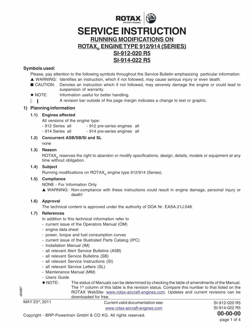
Symbols used:Please, pay attention to the following symbols throughout the Service Bulletin emphasizing particular information.▲ WARNING: Identifies an instruction, which if not followed, may cause serious injury or even death.■ CAUTION: Denotes an instruction which if not followed, may severely damage the engine or could lead to
suspension of warranty.◆ NOTE: Information useful for better handling.
A revision bar outside of the page margin indicates a change to text or graphic.
1) Planning information
1.1) Engines affectedAll versions of the engine type:- 912 Series all - 912 pre-series engines all- 914 Series all - 914 pre-series engines all
1.2) Concurrent ASB/SB/SI and SLnone
1.3) ReasonROTAX
® reserves the right to abandon or modify specifications, design, details, models or equipment at any
time without obligation.
1.4) SubjectRunning modifications on ROTAX® engine type 912/914 (Series).
1.5) ComplianceNONE - For Information Only▲ WARNING: Non-compliance with these instructions could result in engine damage, personal injury or
death!
1.6) ApprovalThe technical content is approved under the authority of DOA Nr. EASA.21J.048.
1.7) ReferencesIn addition to this technical information refer to- current issue of the Operators Manual (OM)- engine data sheet- power, torque and fuel consumption curves- current issue of the Illustrated Parts Catalog (IPC)- Installation Manual (IM)- all relevant Alert Service Bulletins (ASB)- all relevant Service Bulletins (SB)- all relevant Service Instructions (SI)- all relevant Service Letters (SL)- Maintenance Manual (MM)- Users Guide◆ NOTE: The status of Manuals can be determined by checking the table of amendments of the Manual.
The 1st column of this table is the revision status. Compare this number to that listed on theROTAX WebSite: www.rotax-aircraft-engines.com. Updates and current revisions can bedownloaded for free.d0
4987
Current valid documentation see:www.rotax-aircraft-engines.com
SERVICE INSTRUCTION
SI-912-020 R5SI-914-022 R5
00-00-00page 2 of 4
MAY 23rd, 2011
Copyright - BRP-Powertrain GmbH & CO KG. All rights reserved.
2) Material Information
2.1) Material - cost and availabilityPrice and availability will be supplied on request by ROTAX
® Authorized Distributors or their Service Center.
2.2) Special tooling/lubricant-/adhesives-/sealing compound -Price and availability will be supplied on request by ROTAX® Authorized Distributors or their Service Center.
3) Accomplishment / Instructions◆NOTE: Before maintenance, review the entire documentation to make sure you have a complete
understanding of the procedure and requirements to prevent mistakes from an incomplete review of allof the information in this document.
All the measures must be taken and confirmed by the following persons or facilities:- ROTAX
® -Distributors or their Service Center
- Persons with the respective Aviation Authority▲ WARNING: Proceed with this work only in a non-smoking area and not close to sparks or open flames. Switch off
ignition and secure engine against unintentional operation. Secure aircraft against unauthorizedoperation. Disconnect negative terminal of aircraft battery.
▲ WARNING: Risk of scalds and burns! Allow engine to cool sufficiently and use appropriate safety gear whileperforming work.
▲ WARNING: Should removal of a locking device (namely lock tabs, self-locking fasteners) be required whenundergoing disassembly/assembly, always replace with a new one.
◆ NOTE: All work has to be performed in accordance with the relevant Maintenance Manual.
◆ NOTE: The illustrations in this document show the typical construction. They may not represent full detailor the exact shape of the parts which have the same or similar function.Exploded views are no technical drawings and are for reference only. For specific detail, refer tothe current documents of the respective engine type.
Approval of translation to best knowledge and judgement - in any case the original text in German language and themetric units (SI-system) are authoritative.
SI-912-020 R5SI-914-022 R5
00-00-00page 3 of 4
MAY 23rd, 2011
Copyright - BRP-Powertrain GmbH & CO KG. All rights reserved.
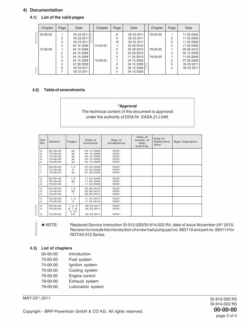
4) Documentation
4.1) List of the valid pages
*ApprovalThe technical content of this document is approved
under the authority of DOA Nr. EASA.21J.048.
4.2) Table of amendments
retpahC egaP etaD retpahC egaP etaD retpahC egaP etaD
00-00-00
00-00-37
12341234567
1102325011023250110232508002514080025140800251408002514080025140800282701102325011023250
00-00-47
00-00-57
890112341234
1102325011023250110232500102825001028250010282500102421180025140800251408002514080025140
00-00-67
00-00-87
00-00-97
1234121234
80023011800230118002301180023011010282508002514080023011800282701102325011023250
◆ NOTE: Replaced Service Instruction SI-912-020/SI-914-022 R4, date of issue November 24th 2010.Revision to include the introduction of a new fuel pump part no. 893110 and part no. 893114 forROTAX 912 Series.
4.3) List of chapters00-00-00 Introduction73-00-00 Fuel system74-00-00 Ignition system75-00-00 Cooling system76-00-00 Engine control78-00-00 Exhaust system79-00-00 Lubrication system
.reS.oN
noitceS segaPfoetaDnoitcerroc
fongiSecnatpecca
foetaDfo.tpecca
.pserytirohtua
foetaD-tnemelpmi
noitaerutangiS/ngiS
00000
00-00-0000-00-3700-00-5700-00-6700-00-87
llallallallalla
8002514080025140800251408002514080025140
*AOD*AOD*AOD*AOD*AOD
111
00-00-0000-00-3700-00-97
3,15
lla
800282708002827080028270
*AOD*AOD*AOD
222
00-00-0000-00-6700-00-97
3,1lla
1
800230118002301180023011
*AOD*AOD*AOD
333
00-00-0000-00-4700-00-87
3,1lla
1
010282500102825001028250
*AOD*AOD*AOD
44
00-00-0000-00-47
3,14
0102421101024211
*AOD*AOD
55
5
00-00-0000-00-37
00-00-97
3,2,1,8,7,6
01,94,3
1102325011023250
11023250
*AOD*AOD
*AOD

SI-912-020SI-914-022
00-00-00page 4 of 4
APRIL 15th, 2008Initial Issue
Copyright - ROTAX®
NOTES
SI-912-020SI-914-022
73-00-00page 1 of 10
APRIL 15th, 2008Initial Issue
Copyright - ROTAX®
SECTION 73-00-00
1) Introduction of a new flexible fuel line assy. part no. 874911 for ROTAX® 912 Series
1.1) General Information(see fig. 1 and 2)In the course of continuous development and for better assembly and maintenance a new flexible fuel line (partno. 874910) has been introduced.Installation of this new fuel line requires the following modifications:- mechanical machining at the intake manifold for the attachment of the cable clamp. At engine repair/general
overhaul be aware that the fixation of the flexible fuel line needs an appropriate contact surface. If necessaryreplace the intake manifold or machine the contact surface according to the following instruction.
The new fuel line has been already installed on the following engines:- 912 A as of S/N 4,410.713
- 912 F as of S/N 4,412.923
- 912 S as of S/N 4,923.384
- 912 UL*) as of S/N 4,408.199
- 912 ULS*) as of S/N 5,647.489
- 912 ULSFR*) as of S/N 4,430.445*) optional installation possible
parts requirement:
Fig New Qty Description Old applicationitem no part no per engine part no
1 874911 1 fuel line assy. 874294 9122 940872 2 banjo bolt M8x1x24 - flexible fuel line3 847795 2 spacer - flexible fuel line4 950141 6 sealing ring A8x13 - banjo bolt5 651430 2 cable clamp 12/M8 - flexible fuel line6 940481 2 hex. screw M8X30 240276 carburetor socket8 942671 2 hex. nut M8 - cable clamp9 866719 2 clamp - flexible fuel line10 950143 3 gasket ring 8.2/13/1.4 - banjo bolt/ clamp block
◆ NOTE: It is not mandatory to retrofit engines with the old stainless steel fuel line!For a retrofit to a flexible fuel line system the following new parts are required:parts requirement:
Fig New Qty Description Old applicationitem no part no per engine part no
881980 1 flex. fuel line retrofit kit retofitting flexible fuel lineconsisting of:
874911 1 fuel line assy. 874294 912940872 2 banjo bolt M8x1x24 - flexible fuel line847795 2 spacer - flexible fuel line950141 6 sealing ring A 8x13 - banjo bolt651430 2 cable clamp 12/M8 - flexible fuel line940481 2 hex. screw M8X30 240276 carburetor socket942671 2 hex. nut M8 - cable clamp866719 2 clamp - flexible fuel line950143 5 gasket ring 8.2/13/1.4 - banjo bolt/ clamp block851325 1 clamp block - 912 - clamp block230150 1 gasket ring 10x14 - clamp block641733 1 hex. screw M10x1x8 - clamp block840511 1 hex. screw M5x16 - clamp block941785 1 banjo bolt kpl. - clamp blockd0
4988

SI-912-020SI-914-022
73-00-00page 2 of 10
APRIL 15th, 2008Initial Issue
Copyright - ROTAX®
956312 1 ring hose nipple - return line250311 2 washer 8.4 - carburetor socket
- Install the flexible fuel line (1) with the double ring hose nipple (13) and sealing ring (10) on the clamp block(11). Tightening torque of banjo screw (14) 10 Nm (90 in. lb.) (see fig. 1).
- Install the ring hose nipple (15) with distance sleeve (3) and sealing ring (4) on the carburetors. Tighteningtorque of banjo screw (2) 10 Nm (90 in. lb.)
◆ NOTE: In case of a retrofit on configurations with steel fuel lines remove the screw connectors (12)and remove remaining sealant residues in a way that they do not get into the carburetor or thefuel system.
- For installation on an old style intake manifold perform the following: Remove the intake manifold and machinethe nut/clamp contact area until the surface is parallel with the sealing surface of the carb socket. Thethickness of the material must not be dressed down less than 10,5 mm (0.413 in.) and should be smooth andflat so that the nut/clamp assembly has an even contact surface (see fig. 2).
- Ensure proper support of the flexible fuel line. Install Hex. screw (6) and washer (7) with 15 Nm (133 in. lb.).Install the cable clamp (5) at the hex. screw (6) of the carburetor socket with the hex. nut (8). Tightening torqueof hex. nut (8) 24 Nm (213 in. lb.)
■ CAUTION: While tightening hex. nut (8), hold hex. screw (6) with a wrench to prevent it from loosening.Always fix the flexible fuel line at the compensation tube with clamps (9) in such a way that no wear is possible.
1.2) Illustrationthe following drawings should convey additional information:
fig. 1
081804
34
2
5
6
8
4
1
1
6
23
4
8
11
13
145
12
129
9
10
7
7
15
15
A
A
A LOCTITE 221fig. 2
min. 10,5 mm (0.413 in.)07313
SI-912-020SI-914-022
73-00-00page 3 of 10
APRIL 15th, 2008Initial Issue
Copyright - ROTAX®
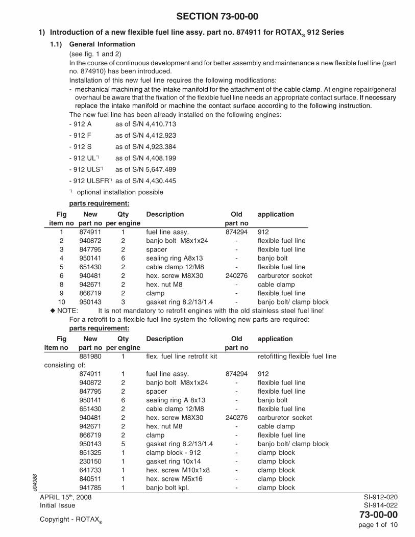
2) Introduction of a new gasket part no. 950226 for fuel pump ROTAX® 912 Series
2.1) General Information(see fig.1)In the course of continuous development a new gasket (1) (part no. 950226) has been introduced.The new gasket has been already installed on the following engines:- 912 A as of S/N 4,410.744- 912 F as of S/N 4,412.929- 912 S as of S/N 4,923.486- 912 UL as of S/N 4,408.421- 912 ULS as of S/N 5,648.605- 912 ULSFR as of S/N 6,374.096The new gasket has been already included in all fuel pumps delivered as spare part:- fuel pump as of S/N 07.002119
parts requirement:
Fig New Qty Description Old applicationitem no part no per engine part no
1 950226 1 gasket 950225 fuel pump
The gasket is interchangeable.
2.2) Illustrationthe following drawings should convey additional information:
◆ NOTE: On the sealing surfaces of the gearbox housing and the fuel pump no sealing compound hasto be used.
fig. 1
B LOCTITE 243
2
1
08353
XXXXXX
part no. (6 digit number)
S/N. (6 or 8 digit number)
XXXXXX
SI-912-020SI-914-022
73-00-00page 4 of 10
APRIL 15th, 2008Initial Issue
Copyright - ROTAX®
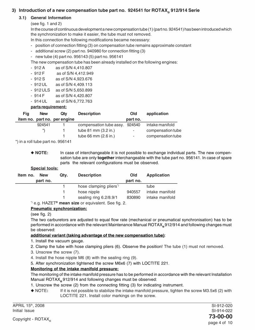
3) Introduction of a new compensation tube part no. 924541 for ROTAX® 912/914 Serie
3.1) General Information(see fig. 1 and 2)In the course of continuous development a new compensation tube (1) (part no. 924541) has been introduced whichthe synchronization to make it easier, the tube must not removed.In this connection the following modifications became necessary:- position of connection fitting (3) on compensation tube remains approximate constant- additional screw (2) part no. 940980 for connection fitting (3)- new tube (4) part no. 956143 (5) part no. 956141The new compensation tube has been already installed on the following engines:- 912 A as of S/N 4,410.807- 912 F as of S/N 4,412.949- 912 S as of S/N 4,923.676- 912 UL as of S/N 4,409.113- 912 ULS as of S/N 5,650.899- 914 F as of S/N 4,420.807- 914 UL as of S/N 6,772.763parts requirement:
Fig New Qty Description Old applicationitem no. part no. per engine part no.
924541 1 compensation tube assy. 924540 intake manifold*) 1 tube 81 mm (3.2 in.) - compensation tube
1 tube 66 mm (2.6 in.) - compensation tube*) in a roll tube part no. 956141
◆ NOTE: In case of interchangeable it is not possible to exchange individual parts. The new compen-sation tube are only together interchangeable with the tube part no. 956141. In case of spareparts the relevant configurations must be observed.
Special tools:
Item no. New Qty. Description Old Applicationpart no. part no.
1 hose clamping pliers*) tube1 hose nipple 940557 intake manifold1 sealing ring 6.2/8.9/1 830890 intake manifold
*) e.g. HAZET® mean size or equivalent. See fig. 2.Pneumatic synchronization:(see fig. 2)The two carburetors are adjusted to equal flow rate (mechanical or pneumatical synchronisation) has to beperformed in accordance with the relevant Maintenance Manual ROTAX® 912/914 and following changes mustbe observed:additional variant (taking advantage of the new compensation tube):1. Install the vacuum gauge.2. Clamp the tube with hose clamping pliers (6). Observe the position! The tube (1) must not removed.3. Unscrew the screw (7).4. Install the hose nipple M6 (8) with the sealing ring (9).5. After synchronization tightened the screw M6x6 (7) with LOCTITE 221.Monitoring of the intake manifold pressure:The monitoring of the intake manifold pressure has to be performed in accordance with the relevant InstallationManual ROTAX® 912/914 and following changes must be observed:1. Unscrew the screw (2) from the connecting fitting (3) for indicating instrument.◆ NOTE: If it is not possible to stabilize the intake manifold pressure, tighten the screw M3.5x6 (2) with
LOCTITE 221. Install color markings on the screw.
SI-912-020 R1SI-914-022 R1
73-00-00page 5 of 10
JULY 28th, 2008
Copyright - ROTAX®
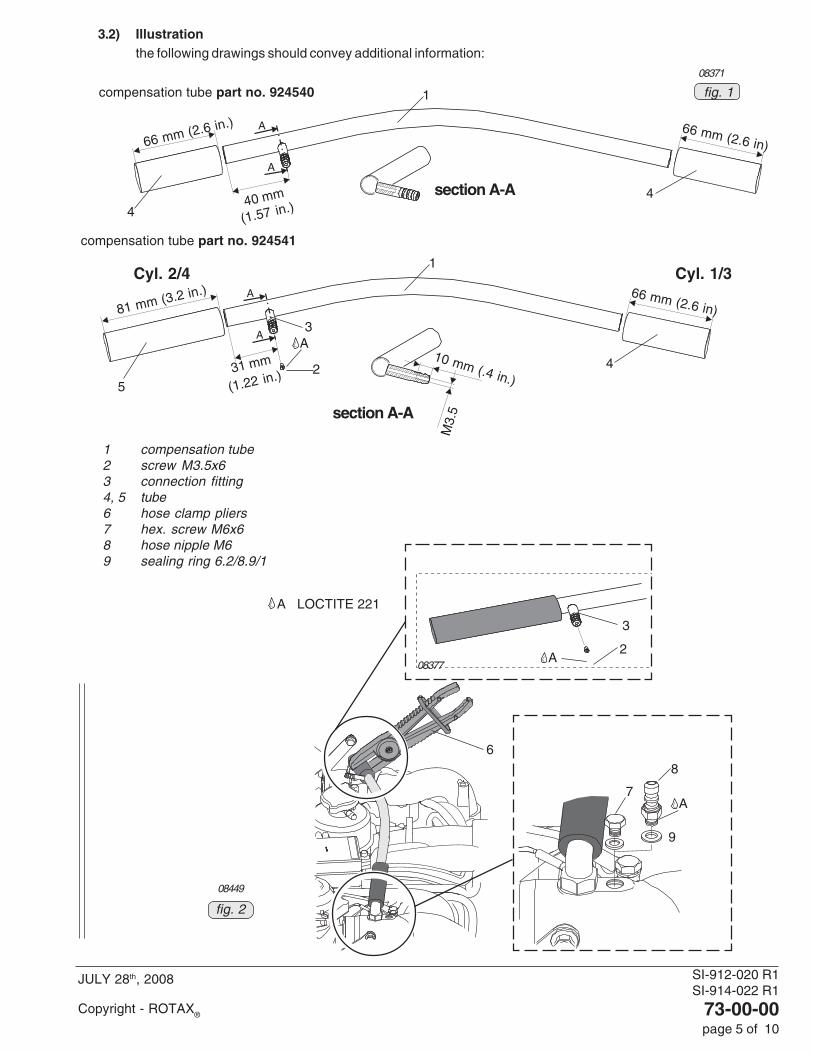
3.2) Illustrationthe following drawings should convey additional information:
1 compensation tube2 screw M3.5x63 connection fitting4, 5 tube6 hose clamp pliers7 hex. screw M6x68 hose nipple M69 sealing ring 6.2/8.9/1
08371
fig. 1
section A-A
section A-A
compensation tube part no. 924540
compensation tube part no. 924541
31 mm
(1.22 in.)
10 mm (.4 in.)
M3.
5
2
40 mm
(1.57 in.)
66 mm (2.6 in.)
81 mm (3.2 in.)
66 mm (2.6 in)
Cyl. 2/4 Cyl. 1/3
A
44
4
5
1
1
3
66 mm (2.6 in)
A LOCTITE 221
08449
6
2
3
A
7
08377
8
9
A
fig. 2

SI-912-020 R5SI-914-022 R5
73-00-00page 6 of 10
MAY 23rd, 2011
Copyright - BRP-Powertrain GmbH & CO KG. All rights reserved.
4. Introduction of a new fuel pump assy. part no. 893110 and part no. 893114 for ROTAX 912 Series
4.1) General Information(see fig. 1 and fig. 2)In the course of continuous development and for better assembly and maintenance a new fuel pump assy. (partno. 893110 and/or part no. 893114) has been introduced.The new fuel pump assy. has been already installed on the following engines:- 912 A as of S/N 4,410.906
- 912 F as of S/N 4,412.990
- 912 S as of S/N 4,924.185
- 912 UL as of S/N 6,770.279
- 912 ULS as of S/N 6,778.296
parts requirement:
Fig New Qty Description Old applicationitem no part no per engine part no
1 893110 1 fuel pump assy. 892542 912 with hose fittings, isolating flange (gasket)and O-ring
893114 1 fuel pump assy. 892546 912 with attached hoses, isolating flange(gasket) and O-ring
7 950228 1 isolating flange (gasket) - fuel pump assy.8 631870 1 O-ring - fuel pump assy.13 874335 1 fuel hose - fuel pump assy. (fuel outlet)14 874345 1 fuel hose - fuel pump assy. (fuel inlet)15 230150 1 gasket ring - fuel pump assy.
◆ NOTE: In case of an upgrade the parts listed above have to be used, the fuel pump must be installed using thenew isolating flange (gasket). Ammendments concerning service or installation need to be adhered to.Proof of certification to the latest requirements such as FAR or EASA has to be supplied by the aircraftmanufacturer.
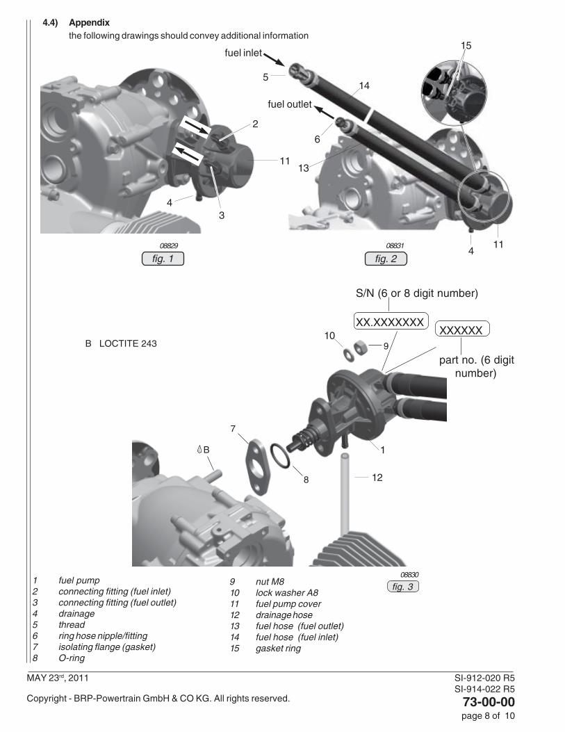
4.2) Changes concerning installation(see fig. 1 and fig. 2)
Connecting to fuel pump (1) with push-on fittings. See fig.1.Fuel inlet (2):
outside dia ............... 8 mm (0.31 in.)slip-on length for hose attachment:max. 22 mm (0.87 in.)
Fuel outlet (3):outside dia ............... 6 mm (0.25 in.)slip-on length for hose attachment:max. 22 mm (0.87 in.)
Drainage (4):inside dia .................. 6 mm (0.25 in.)slip-on length for hose attachment:max. 22 mm (0.87 in.)
■ CAUTION: When mounting the fuel line to the fuel pump make sure that excessive force is not appliedto the fuel pump.
■ CAUTION: Use the maximal possible slip-on length for mounting hose. Secure with appropriate hoseclamps. Route the lines without kinks and avoid tight bends.
Connecting to fuel pump (1) with attached hoses. See fig. 2.Fuel inlet (2):
thread (5) .................. 9/16-18 UNF (AN-6)tightening torque ....... 15 Nm (135 in.lb)
Fuel outlet (3):ring hose nipple/fitting (6) 3/4 DIN 7642
Drainage (4):outside dia ............... 6 mm (0.25 in.)

SI-912-020 R5SI-914-022 R5
73-00-00page 7 of 10
MAY 23rd, 2011
Copyright - BRP-Powertrain GmbH & CO KG. All rights reserved.
slip-on length for hose attachment:max. 22 mm (0.87 in.)■ CAUTION: Route the lines without kinks and avoid tight bends.
▲ WARNING: It must be made sure that the drainage line is connected and routed to an appropriatedrainage area, otherwise it might be possible that overflowing fuel reaches hot engineparts. RISK OF FIRE!
■ CAUTION: Drainage line have to be routed into a ram-air and vacuum free zone, according to therequirements and release of BRP-Powertrain. The drainage line must not be routed intothe slipstream. Ram pressure or vacuum impair the fuel pressure.
- The drainage line has to be installed in such a way that the excessive fuel flows to a non-hazard area.- The installed drainage line must have a continuous slope downwards.- The drainage line must be protected against any kind of blockage (e.g. formation of ice).
■ CAUTION: If a auxiliary electrical fuel pump is used a check valve (part no. 874532) should beused.The check valve must have a low cracking pressure and must be installed in aparallel circuit as per the Installation Manual 912/914 Series.
■ CAUTION: To prevent loss of fuel the fuel return line orifice size is max. 0.35 mm (0.014 in.). Seelatest Installation Manual 912/914 Series.
4.2) Changes concerning maintenance(see fig. 1 to fig. 4)
4.3.1) Maintenance checksSee latest Maintenance Manual (Line), maintenance checklist.- Besides inspection of the fuel lines also the drainage lines (if applicable) must be inspected - check all
hoses for damage, leakage, hardening by heat, porosity, loose fittings, secure mounting and sharpbends.
4.3.2) Removal of the fuel pumpSee latest Maintenance Manual (Heavy).■ CAUTION: Replace the isolating flange (gasket) on reinstallation of the fuel pump. It is also required
to replace the O-ring at every installation.
4.3.3) Inspection of the fuel pumpSee latest Maintenance Manual (Heavy).■ CAUTION: The fuel pump cover (11) must not be opened. The safety marks have to be intact.■ CAUTION: The connecting fittings (2,3) must be checked for secure mounting and leakage. If the
fittings or rather the fuel hoses (13,14) have to be removed clean and reinstall with newgasket ring and LOCTITE 243 and a tightening torque of 10 Nm (90 in.lb).
4.3.4) Installation of the fuel pumpSee latest Maintenance Manual (Heavy).■ CAUTION: It is necessary to use a new isolating flange (gasket) and a new O-ring. Do not reuse the
old isolating flange or the old O-ring.◆ NOTE: On the mating surfaces of the gearbox housing and the fuel pump flange no sealant is
necessary.Install fuel pump with new isolating flange (7) and O-ring (8). Secure and tighten equally the hex screw-nuts M8 (9) with lock washer A8 (10) using LOCTITE 243 - apply a torque of 15 Nm (135 in.lb).
◆ NOTE: LOCTITE 243 has to be re-applied on each (re-)assembly of the fuel pump.
Reconnect fuel lines.Conduct test run including ignition check and leakage test.
SI-912-020 R5SI-914-022 R5
73-00-00page 8 of 10
MAY 23rd, 2011
Copyright - BRP-Powertrain GmbH & CO KG. All rights reserved.
4.4) Appendixthe following drawings should convey additional information
fig. 208831
fig. 108829
4
1
10B LOCTITE 243 9
S/N (6 or 8 digit number)
XX.XXXXXXX
1 fuel pump2 connecting fitting (fuel inlet)3 connecting fitting (fuel outlet)4 drainage5 thread6 ring hose nipple/fitting7 isolating flange (gasket)8 O-ring
XXXXXX
part no. (6 digitnumber)
7
8
3
6
11
2
5
B
411
fuel inlet
fuel outlet
9 nut M810 lock washer A811 fuel pump cover12 drainage hose13 fuel hose (fuel outlet)14 fuel hose (fuel inlet)15 gasket ring
08830
fig. 3
12
14
13
15
SI-912-020 R5SI-914-022 R5
73-00-00page 9 of 10
MAY 23rd, 2011
Copyright - BRP-Powertrain GmbH & CO KG. All rights reserved.
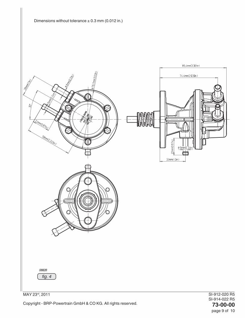
fig. 4
Dimensions without tolerance ± 0.3 mm (0.012 in.)
08828
SI-912-020 R5SI-914-022 R5
73-00-00page 10 of 10
MAY 23rd, 2011
Copyright - BRP-Powertrain GmbH & CO KG. All rights reserved.
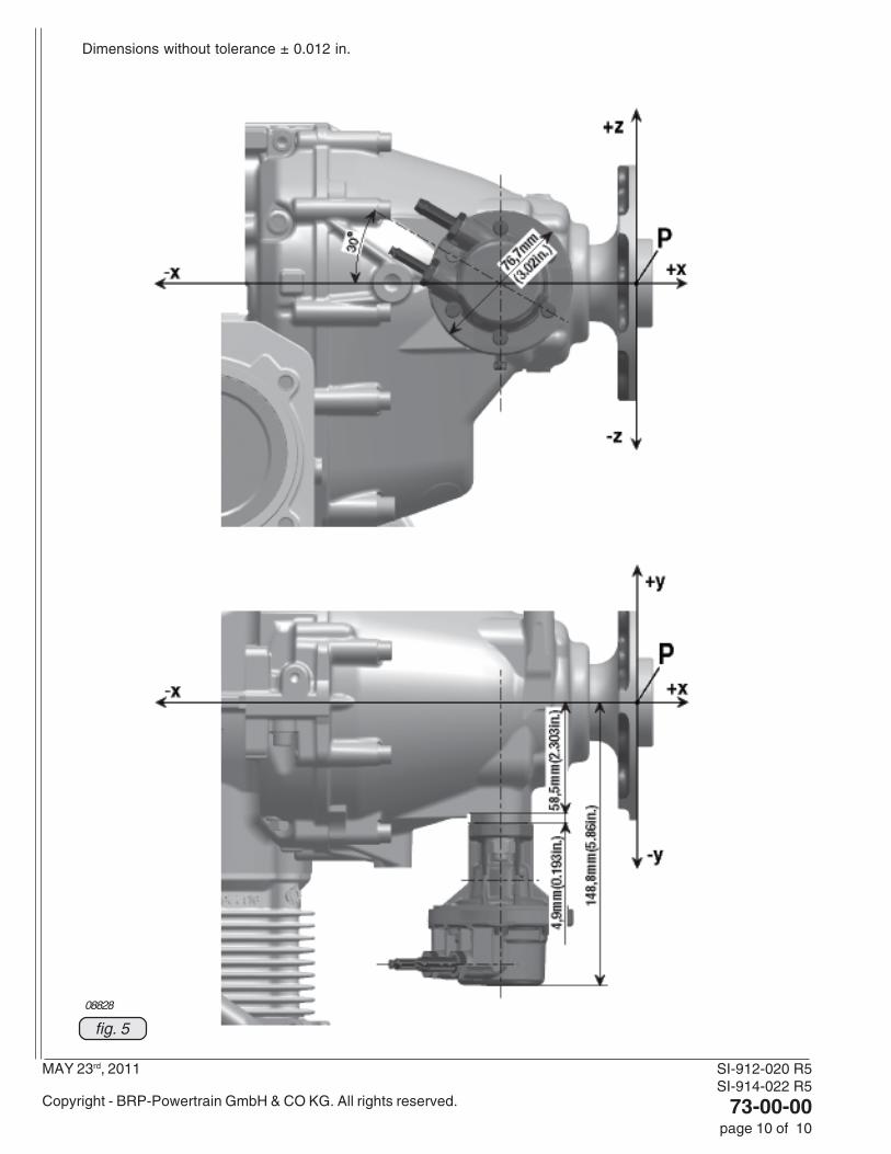
fig. 5
08828
Dimensions without tolerance ± 0.012 in.

SI-912-020 R3SI-914-022 R3
74-00-00page 1 von 4
MAY 28th, 2010
Copyright - BRP-Powertrain GmbH & CO KG. All rights reserved.
SECTION 74-00-00
1.) Introduction of a advanced start module (easy starting device for the electronic module)
1.1) General Information
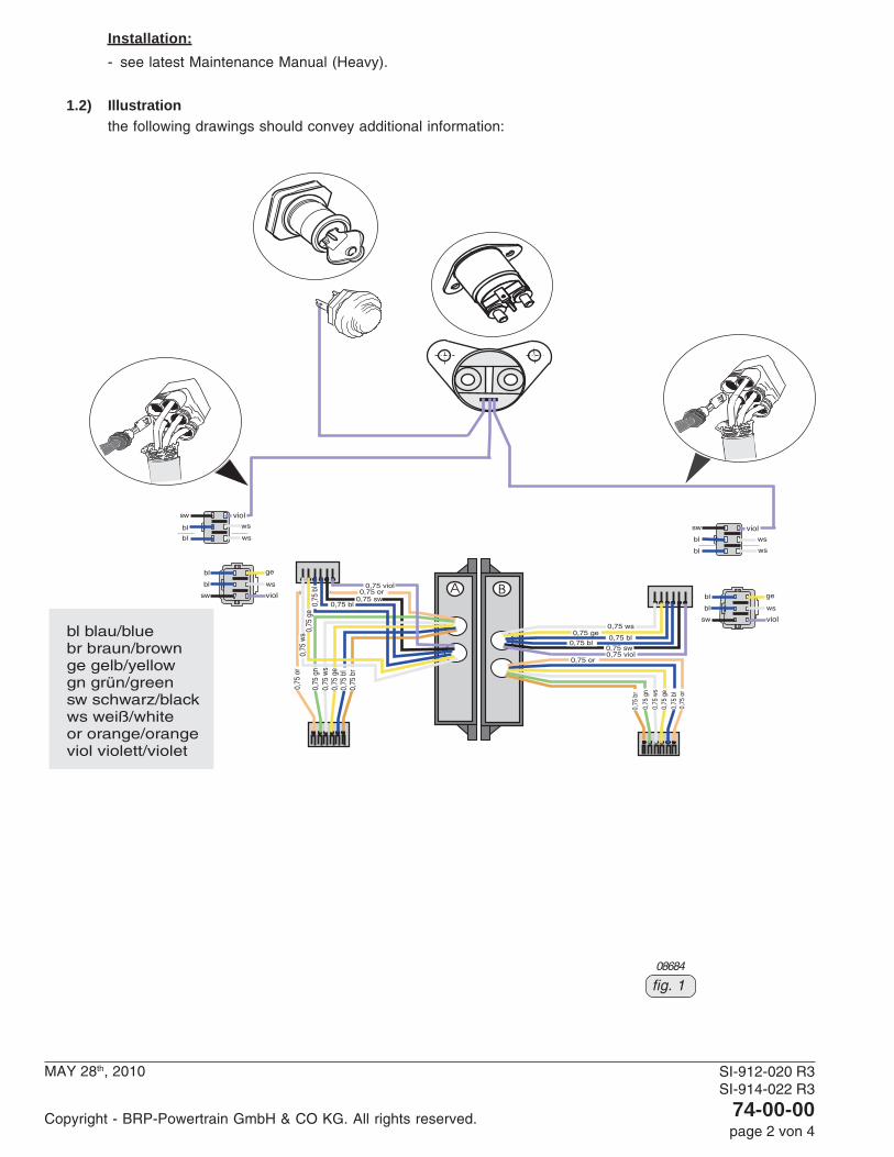
(see fig. 1and 2)In the course of further development and standardization an electronic module for delayed start up ignition timinghas been introduced. This module can be activated by a 12 V signal. Without this optional 12V activation thefunction works the same way as on the well-proven previous module.In this context the following needs to be considered:- 1 wire of each module circuit A and circuit B (6-pole) to start relay control signal wire(see position 26 in fig.
1) must be supplied by the aircraft manufacturer. Therefore the rubber plug of the pin terminal must be removedbefore!
- Time factor for delaying ignition timing at start until switching to advanced ignition: After starting the engineand as soon as the starter/relay is not powered anymore, the engine continues to further run for 3-8 secondswith delayed ignition.
- Do not connect the signal wire to the electric starter motor - as the circuit has not voltage protection.- Do not power the advanced start terminal permanently with 12V. The delay timer function would be bypassed
and charging speed might vary (depending on internal tolerances, trigger gap etc.).The new electronic modules with a starting device have been already installed on the following engines:- 912 S as of S/N 4,923.847
- 912 ULS as of S/N 6,775.360
- 912 ULSFR as of S/N 6,775.360
List of part no.:
Item no. New Qty. Description Old Applicationpart no. part no.966872 1 fly wheel hub 966871 ignition system881280 1 soft start port ignition system
consisting of:966727 2 SMD electronic module 966726 ignition system827800 1 disc A 5.5 ignition system240186 2 allen screw M5x25 ignition system945750 1 lock washer A5 ignition system260130 2 cable grommet ignition system265275 2 faston connector ignition system
◆ NOTE: Engines having an ignition system which is already equipped with the new 6-pin connectorscan be upgraded with both the new module and the new fly wheel hub. Older engines (not having6-pin connectors) can only be upgraded with the new fly wheel hub. As a retrofit would requireconsiderable changes concerning the wiring.
Technical background information:
Differences between electronic module part no. 966726 and part no. 966727:
current 966726 new 966727
fly wheel hub
ignition point at start 966871 current 4° Before T.D.C. 4° Before T.D.C.
966872 new 3° After T.D.C. 3° After T.D.C.
time delay for ignition at start: none 3 - 8 sec.
Switching to advanced ignition: from 650 to 1000 RPM after the expiration ofdepending on trigger gap the time delay (3-8 sec.)
ignition timing in normal operation: 26° before T.D.C. 26° before T.D.C.
d049
37
SI-912-020 R3SI-914-022 R3
74-00-00page 2 von 4
MAY 28th, 2010
Copyright - BRP-Powertrain GmbH & CO KG. All rights reserved.
Installation:
- see latest Maintenance Manual (Heavy).
1.2) Illustration
the following drawings should convey additional information:
08684
fig. 1
SI-912-020 R3SI-914-022 R3
74-00-00page 3 von 4
MAY 28th, 2010
Copyright - BRP-Powertrain GmbH & CO KG. All rights reserved.
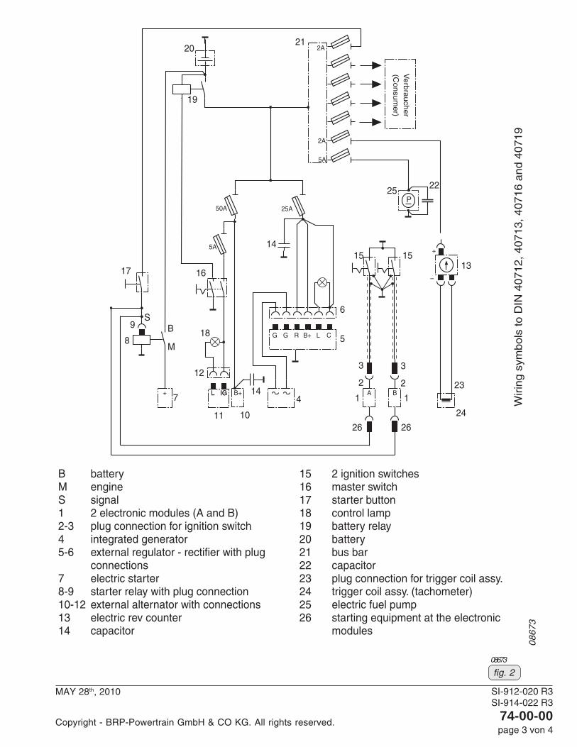
08673
fig. 2

SI-912-020 R4SI-914-022 R4
74-00-00page 4 von 4
NOVEMBER 24th, 2010
Copyright - BRP-Powertrain GmbH & CO KG. All rights reserved.
29 mm
(1.14 in) New
22 mm
(0.87 in)
08685
fig. 3
29 m
m (1
.14
in) N
ew
22 m
m (0
.87
in)
2.) Introduction of an alternative spark plug part no. 897259 for ROTAX 914® Series
2.1) General Information
In the course of continuous development an alternative spark plug has been introduced.
2.2) Interchangeability of parts
- All parts are interchangeable.
parts requirement:
Fig New Qty Description Old applicationitem. no. part no. per engine part no.
897259 8 spark plug DPR9EA-9 - ignition system
◆ NOTE: Spark plug part no. 897257 with specification X27EPR-U9 is interchangeable. Any mixing of sparkplug part no. 897259 and part no. 897257 should be avoided.
2.3) Removal and installation
- see latest Maintenance Manual (Line).
SI-912-020SI-914-022
75-00-00page 1 von 4
APRIL 15th, 2008Initial Issue
Copyright - ROTAX®
SECTION 75-00-00
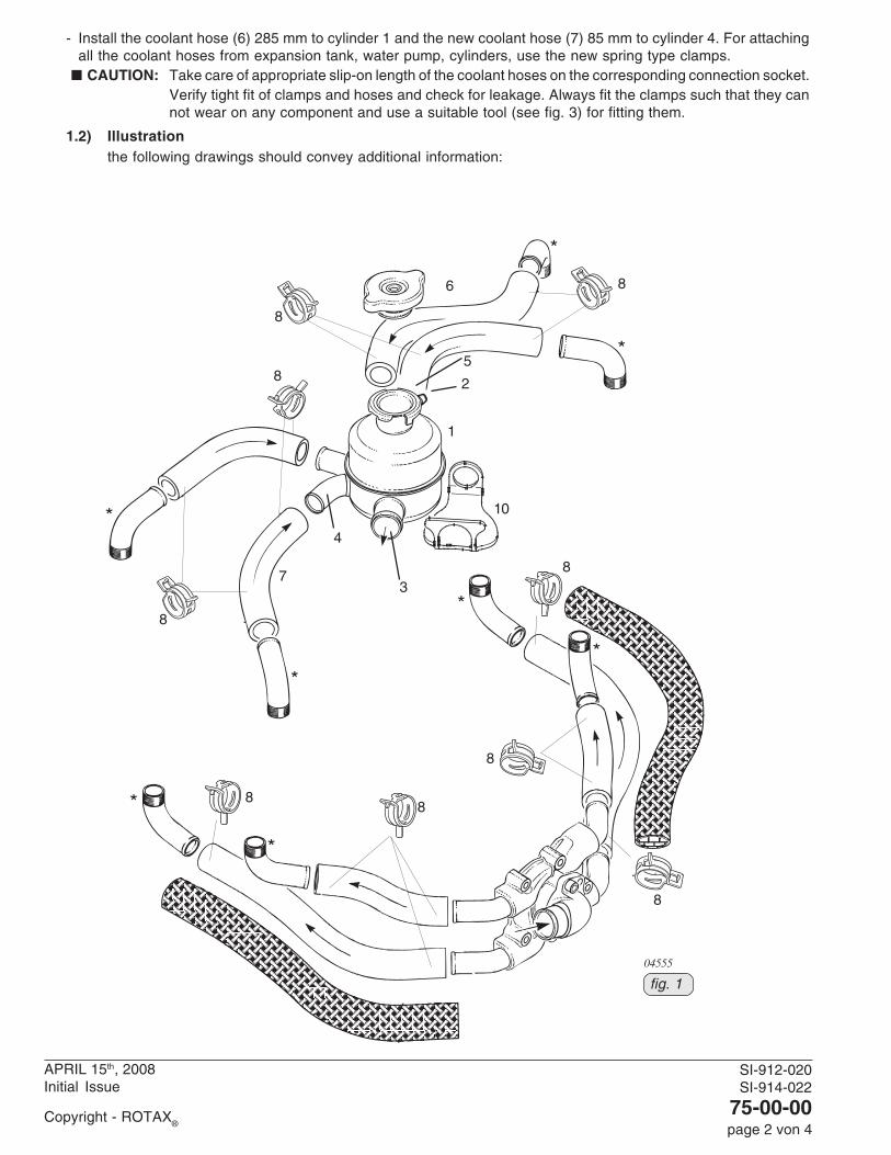
1.) Introduction of a new expansion tank assy.
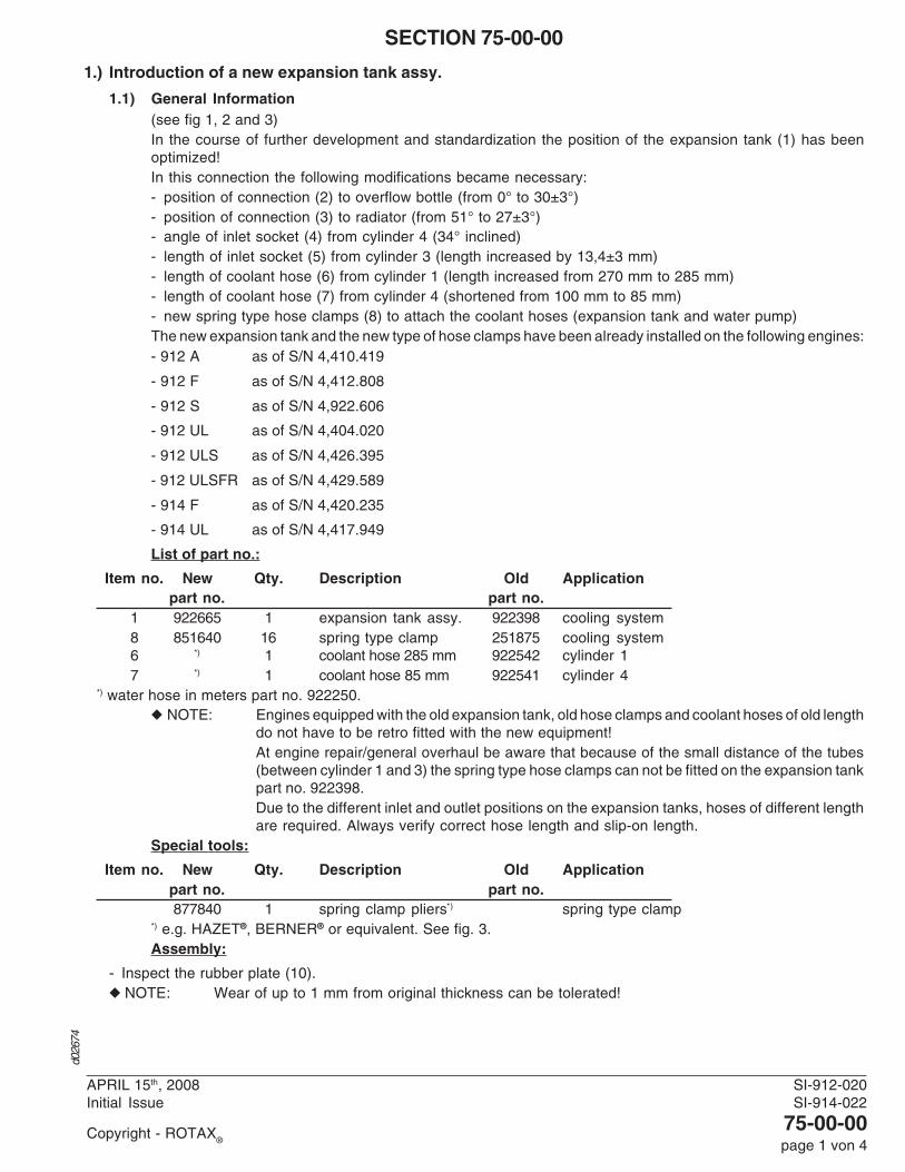
1.1) General Information(see fig 1, 2 and 3)In the course of further development and standardization the position of the expansion tank (1) has beenoptimized!In this connection the following modifications became necessary:- position of connection (2) to overflow bottle (from 0° to 30±3°)- position of connection (3) to radiator (from 51° to 27±3°)- angle of inlet socket (4) from cylinder 4 (34° inclined)- length of inlet socket (5) from cylinder 3 (length increased by 13,4±3 mm)- length of coolant hose (6) from cylinder 1 (length increased from 270 mm to 285 mm)- length of coolant hose (7) from cylinder 4 (shortened from 100 mm to 85 mm)- new spring type hose clamps (8) to attach the coolant hoses (expansion tank and water pump)The new expansion tank and the new type of hose clamps have been already installed on the following engines:- 912 A as of S/N 4,410.419
- 912 F as of S/N 4,412.808
- 912 S as of S/N 4,922.606
- 912 UL as of S/N 4,404.020
- 912 ULS as of S/N 4,426.395
- 912 ULSFR as of S/N 4,429.589
- 914 F as of S/N 4,420.235
- 914 UL as of S/N 4,417.949
List of part no.:
Item no. New Qty. Description Old Applicationpart no. part no.
1 922665 1 expansion tank assy. 922398 cooling system8 851640 16 spring type clamp 251875 cooling system6 *) 1 coolant hose 285 mm 922542 cylinder 17 *) 1 coolant hose 85 mm 922541 cylinder 4
*) water hose in meters part no. 922250.◆ NOTE: Engines equipped with the old expansion tank, old hose clamps and coolant hoses of old length
do not have to be retro fitted with the new equipment!At engine repair/general overhaul be aware that because of the small distance of the tubes(between cylinder 1 and 3) the spring type hose clamps can not be fitted on the expansion tankpart no. 922398.Due to the different inlet and outlet positions on the expansion tanks, hoses of different lengthare required. Always verify correct hose length and slip-on length.
Special tools:
Item no. New Qty. Description Old Applicationpart no. part no.877840 1 spring clamp pliers*) spring type clamp
*) e.g. HAZET®, BERNER® or equivalent. See fig. 3.Assembly:
- Inspect the rubber plate (10).◆ NOTE: Wear of up to 1 mm from original thickness can be tolerated!
d026
74
SI-912-020SI-914-022
75-00-00page 2 von 4
APRIL 15th, 2008Initial Issue
Copyright - ROTAX®
- Install the coolant hose (6) 285 mm to cylinder 1 and the new coolant hose (7) 85 mm to cylinder 4. For attachingall the coolant hoses from expansion tank, water pump, cylinders, use the new spring type clamps.
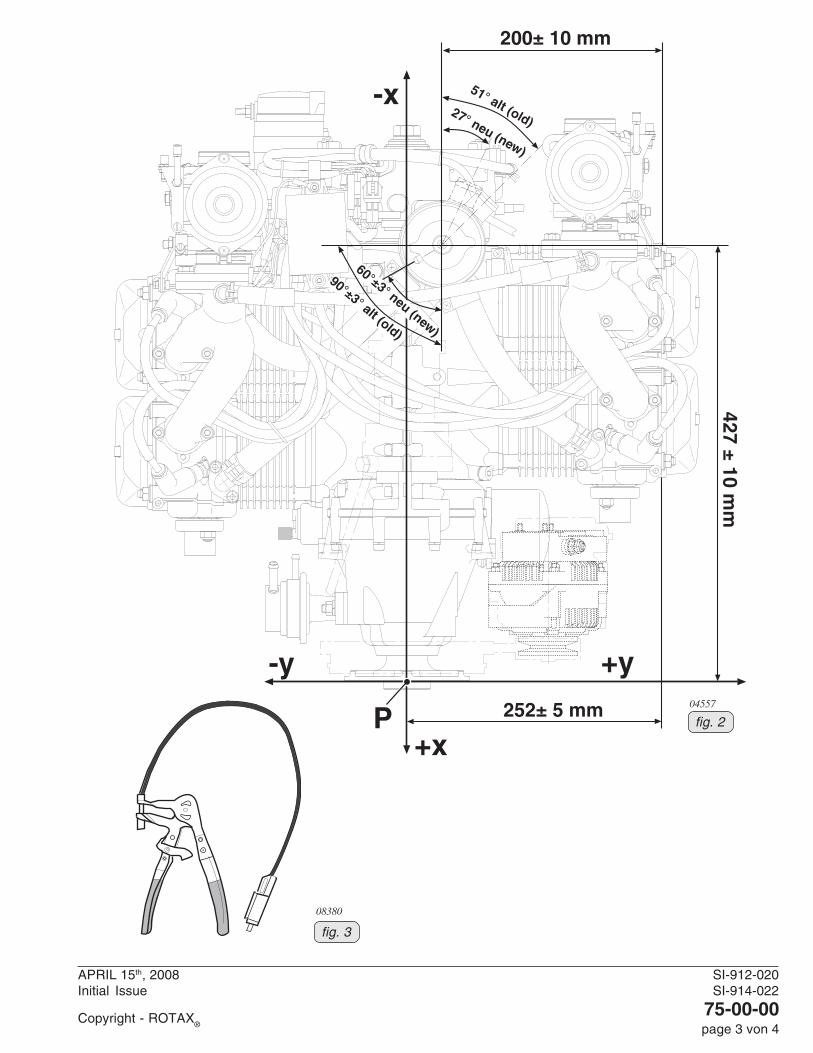
■ CAUTION: Take care of appropriate slip-on length of the coolant hoses on the corresponding connection socket.Verify tight fit of clamps and hoses and check for leakage. Always fit the clamps such that they cannot wear on any component and use a suitable tool (see fig. 3) for fitting them.
1.2) Illustrationthe following drawings should convey additional information:
04555
fig. 1
2
1
38
10
8
8
8
8
88
8
4
7
8
6
5
SI-912-020SI-914-022
75-00-00page 3 von 4
APRIL 15th, 2008Initial Issue
Copyright - ROTAX®
-x
+x
-y +y
P
200± 10 mm
427 ± 10 mm
252± 5 mm
51° alt (old)27° neu (new)
60°±3° neu (new)
90°±3° alt (old)
04557
08380
fig. 3
fig. 2

SI-912-020SI-914-022
75-00-00page 4 von 4
APRIL 15th, 2008Initial Issue
Copyright - ROTAX®
NOTES
SI-912-020 R2SI-914-022 R2
76-00-00page 1 von 4
NOVEMBER 03rd, 2008
Copyright - ROTAX®
SECTION 76-00-00
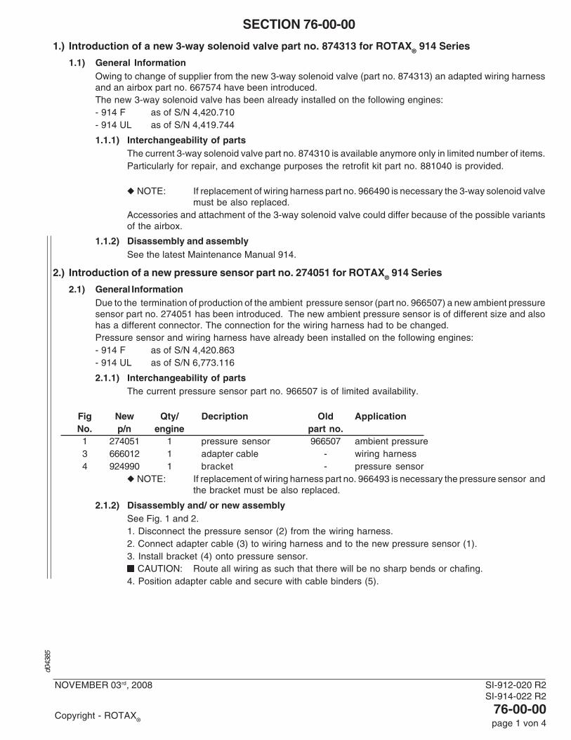
1.) Introduction of a new 3-way solenoid valve part no. 874313 for ROTAX® 914 Series
1.1) General InformationOwing to change of supplier from the new 3-way solenoid valve (part no. 874313) an adapted wiring harnessand an airbox part no. 667574 have been introduced.The new 3-way solenoid valve has been already installed on the following engines:- 914 F as of S/N 4,420.710- 914 UL as of S/N 4,419.744
1.1.1) Interchangeability of partsThe current 3-way solenoid valve part no. 874310 is available anymore only in limited number of items.Particularly for repair, and exchange purposes the retrofit kit part no. 881040 is provided.
◆ NOTE: If replacement of wiring harness part no. 966490 is necessary the 3-way solenoid valvemust be also replaced.
Accessories and attachment of the 3-way solenoid valve could differ because of the possible variantsof the airbox.
1.1.2) Disassembly and assemblySee the latest Maintenance Manual 914.
2.) Introduction of a new pressure sensor part no. 274051 for ROTAX® 914 Series
2.1) General InformationDue to the termination of production of the ambient pressure sensor (part no. 966507) a new ambient pressuresensor part no. 274051 has been introduced. The new ambient pressure sensor is of different size and alsohas a different connector. The connection for the wiring harness had to be changed.Pressure sensor and wiring harness have already been installed on the following engines:- 914 F as of S/N 4,420.863- 914 UL as of S/N 6,773.116
2.1.1) Interchangeability of partsThe current pressure sensor part no. 966507 is of limited availability.
Fig New Qty/ Decription Old ApplicationNo. p/n engine part no.1 274051 1 pressure sensor 966507 ambient pressure3 666012 1 adapter cable - wiring harness4 924990 1 bracket - pressure sensor
◆ NOTE: If replacement of wiring harness part no. 966493 is necessary the pressure sensor andthe bracket must be also replaced.
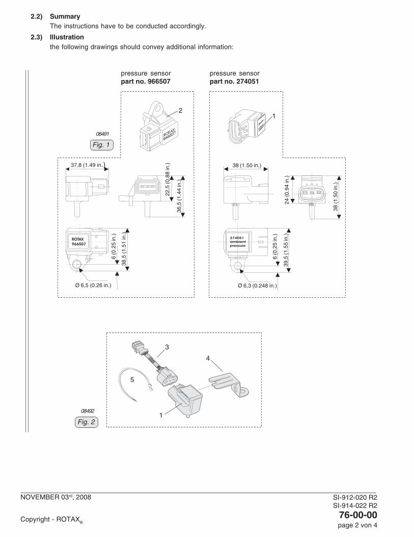
2.1.2) Disassembly and/ or new assemblySee Fig. 1 and 2.1. Disconnect the pressure sensor (2) from the wiring harness.2. Connect adapter cable (3) to wiring harness and to the new pressure sensor (1).3. Install bracket (4) onto pressure sensor.■■■■■ CAUTION: Route all wiring as such that there will be no sharp bends or chafing.4. Position adapter cable and secure with cable binders (5).
d043
85
SI-912-020 R2SI-914-022 R2
76-00-00page 2 von 4
NOVEMBER 03rd, 2008
Copyright - ROTAX®
2.2) SummaryThe instructions have to be conducted accordingly.
2.3) Illustrationthe following drawings should convey additional information:
Fig. 1
08491
1
pressure sensorpart no. 966507
4
Fig. 2
08492
2
5
1
3
37,8 (1.49 in.) 38 (1.50 in.)
36,5
(1.4
4 in
.)
38,
5 (1
.51
in.)
38 (1
.50
in.)
24 (0
.94
in.)
39,5
(1.5
5 in
.)
121212121212121212 22
,5 (0
.88
in.)
6 (0
.25
in.)
6 (0
.25
in.)
Ø 6,5 (0.26 in.) Ø 6,3 (0.248 in.)
pressure sensorpart no. 274051
SI-912-020 R2SI-914-022 R2
76-00-00page 3 von 4
NOVEMBER 03rd, 2008
Copyright - ROTAX®
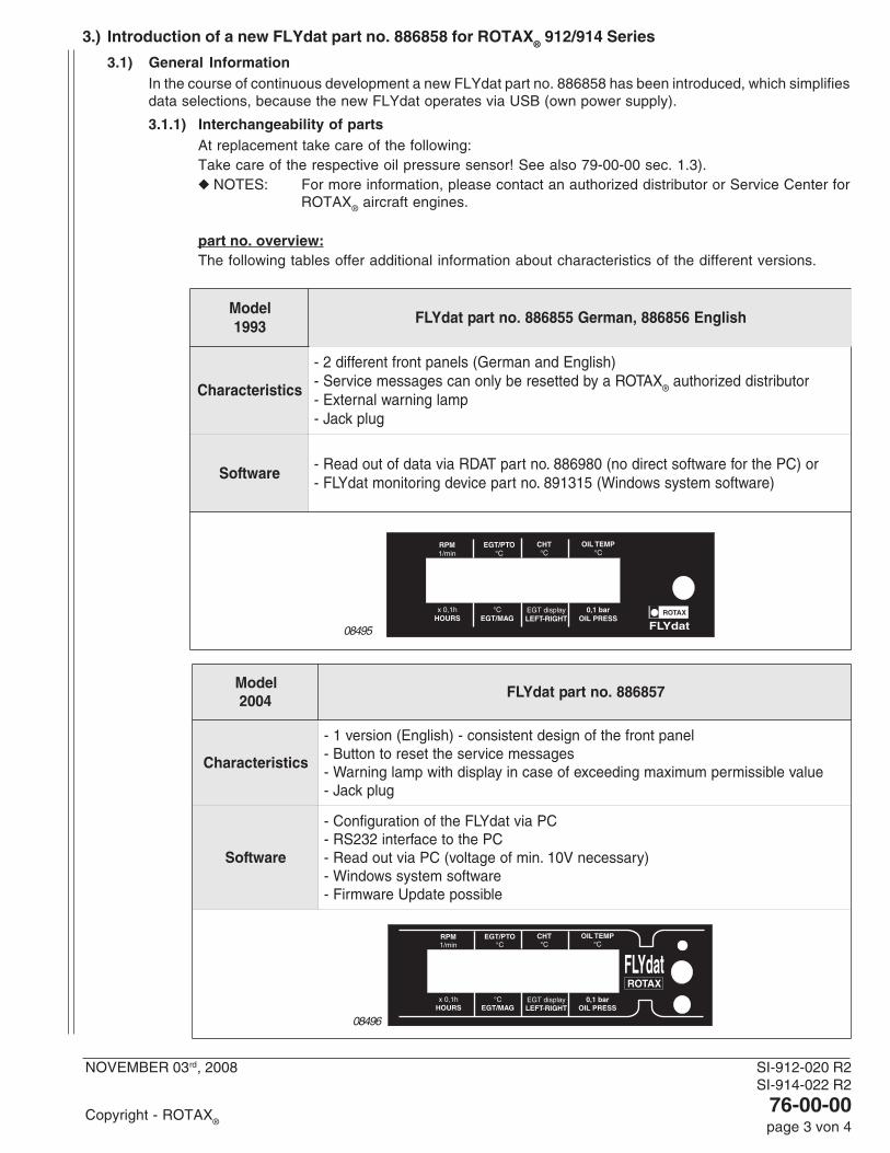
3.) Introduction of a new FLYdat part no. 886858 for ROTAX® 912/914 Series
3.1) General InformationIn the course of continuous development a new FLYdat part no. 886858 has been introduced, which simplifiesdata selections, because the new FLYdat operates via USB (own power supply).
3.1.1) Interchangeability of partsAt replacement take care of the following:Take care of the respective oil pressure sensor! See also 79-00-00 sec. 1.3).◆ NOTES: For more information, please contact an authorized distributor or Service Center for
ROTAX® aircraft engines.
part no. overview:The following tables offer additional information about characteristics of the different versions.
ledoM3991
hsilgnE658688,namreG558688.ontraptadYLF
scitsiretcarahC
)hsilgnEdnanamreG(slenaptnorftnereffid2-XATORaybdetteserebylnonacsegassemecivreS- ® rotubirtsiddezirohtua
pmalgninrawlanretxE-gulpkcaJ-
erawtfoS ro)CPehtroferawtfostceridon(089688.ontrapTADRaivatadfotuodaeR-)erawtfosmetsysswodniW(513198.ontrapecivedgnirotinomtadYLF-
ledoM4002
758688.ontraptadYLF
scitsiretcarahC
lenaptnorfehtfongisedtnetsisnoc-)hsilgnE(noisrev1-segassemecivresehtteserotnottuB-
eulavelbissimrepmumixamgnideecxefoesacniyalpsidhtiwpmalgninraW-gulpkcaJ-
erawtfoS
CPaivtadYLFehtfonoitarugifnoC-CPehtotecafretni232SR-
)yrassecenV01.nimfoegatlov(CPaivtuodaeR-erawtfosmetsysswodniW-elbissopetadpUerawmriF-
08495
08496
SI-912-020 R2SI-914-022 R2
76-00-00page 4 von 4
NOVEMBER 03rd, 2008
Copyright - ROTAX®
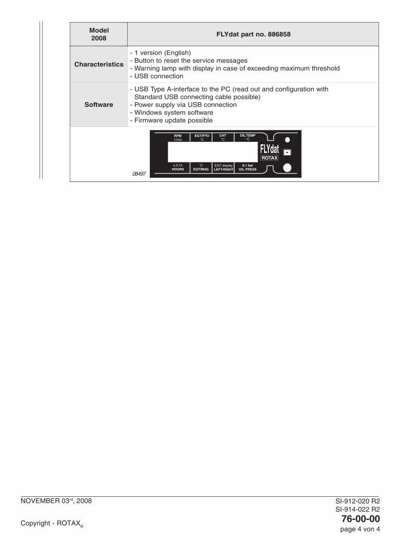
ledoM8002
858688.ontraptadYLF
scitsiretcarahC
)hsilgnE(noisrev1-segassemecivresehtteserotnottuB-
dlohserhtmumixamgnideecxefoesacniyalpsidhtiwpmalgninraW-noitcennocBSU-
erawtfoS
htiwnoitarugifnocdnatuodaer(CPehtotecafretni-AepyTBSU-)elbissopelbacgnitcennocBSUdradnatS
noitcennocBSUaivylppusrewoP-erawtfosmetsysswodniW-elbissopetadpuerawmriF-
08497

SI-912-020 R3SI-914-022 R3
78-00-00page 1 von 2
MAY 28th, 2010
Copyright - BRP-Powertrain GmbH & CO KG. All rights reserved.
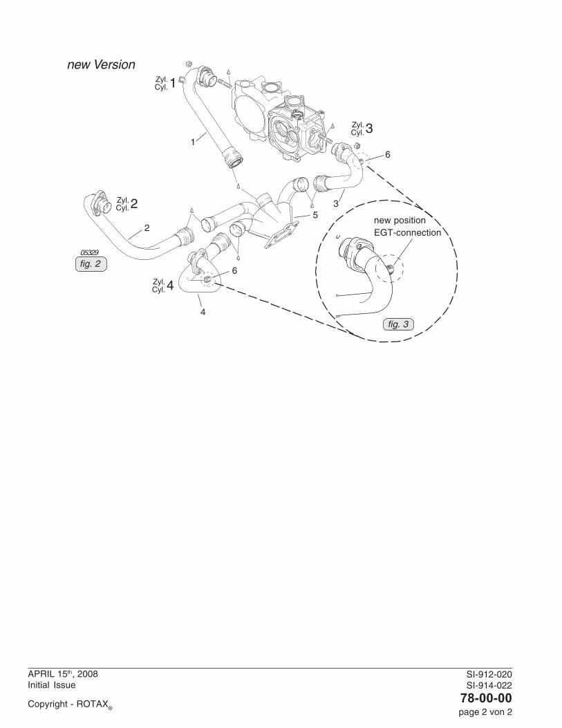
SECTION 78-00-001) Introduction of new exhaust bends an exhaust manifold on ROTAX® 914
1.1) General Information(see fig. 1 to 2)Owing to continuous further development, the exhaust bends were slightly re-worked. The couplings wereoptimized for their position.- Position of the EGT connections (6) to the exhaust bends for cylinders 3 and 4 were routed such that
installation of the new drip trays is possible.The new exhaust bends and the new exhaust manifold have already been built into all of the following engines:- 914 F as of S/N 4,420.364- 914 UL as of S/N 4,418.248parts requirement:
Fig New Qty Description Old applicationitem no part no per engine part no
1 979425 1 exhaust bend assy cyl. 1 979420/421/422 ROTAX® 914
2 979435 1 exhaust bend assy cyl. 2 979430/431/432 ROTAX® 914
3 979445 1 exhaust bend assy cyl. 3 979440/441/442 ROTAX® 914
4 979455 1 exhaust bend assy cyl. 4 979450/451/452 ROTAX® 914
5 979413 1 exhaust manifold 979411 ROTAX® 914
◆ NOTE: If replacement of any single old part number is necessary, you must replace it with the sameold part number. If the old part number is not available, the entire assembly including all 4 pipesand manifold must be replaced with new part numbers. New style pipes and manifold are notinterchangeable with old style.
1.2) Illustrationthe following drawings should convey additional information:
d047
95
Zyl.Cyl.1
Zyl.Cyl.2
Zyl.Cyl.3
Zyl.Cyl.4
04825
old version
fig. 1
SI-912-020SI-914-022
78-00-00page 2 von 2
APRIL 15th, 2008Initial Issue
Copyright - ROTAX®
Zyl.Cyl.1
Zyl.Cyl.2
Zyl.Cyl.3
Zyl.Cyl.4
05329
fig. 2
new positionEGT-connection
fig. 3
new Version
6
6
1
2
4
35

SI-912-020 R2SI-914-022 R2
79-00-00page 1 of 4
NOVEMBER 03rd, 2008
Copyright - ROTAX®
SECTION 79-00-00
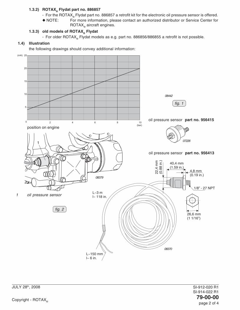
1.) Introduction of a new oil pressure sensor for ROTAX® 912/914 Series
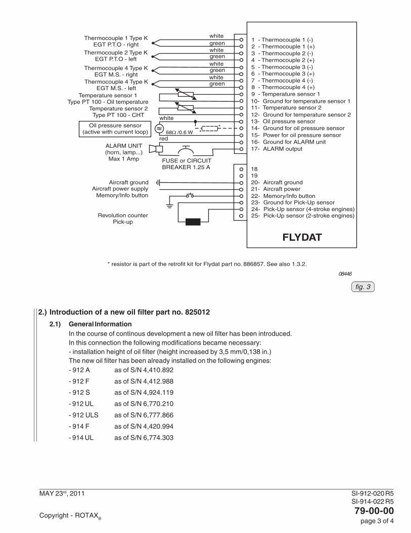
1.1) new oil pressure sensor(see fig. 1, 2 and 3)In the course of further development and standardization a new oil pressure sensor part no. 956413 has beenintroduced.The new oil pressure sensor has been already installed on the following engines:- 912 A as of engine S/N 4,410.817- 912 F as of engine S/N 4,412.955- 912 S as of engine S/N 4,923.748- 912 UL as of engine S/N 4,409.340- 912 ULS as of engine S/N 5,651.797- 914 F as of engine S/N 4,420.825- 914 UL as of engine S/N 6,773.026- location: oil pump housing- wiring connection for instrument:
The sensor cable is approx. 3 m long and has 3 leads. The Black lead is not to be connected and has nofunction. The Red lead from the sensor has to be connected to the positive bus via a fuse or circuit breaker.The White lead (output signal) has to be connected directly to the instrument. See also the relevantinstructions of the instrument supplier/aircraft manufacturer for correct connection and wiring.
◆ NOTE: The sensor cable can be modified in its length according to the installation situation, e.g.shortened or extended. For extension an appropriate, commercially available cable can beused. A resistance cable or similar is not necessary.
- wire gauge: stranded wire, 0,5 mm2 (AWG 20)- cable length: 3 m (118 in.)- operating temperature range:
min.: - 40 °C (-40 °F)max.: + 125 °C (+ 257 °F)
- grounding: via engine block/airframe ground- output signal:
In contrary to the oil pressure sensor offered up to now, which was providing the signal on the basis of asensor resistance variation, the new oil pressure sensor operates on basis of a current variation. This hasto be taken into account for the selection of the appropriate cockpit instrument.
■ CAUTION: The graph current over pressure has been determined, and is effective at the followingconditions only (see fig. 1).
ambient temperature: 20 °C (68 °F)tolerance: ± 3%
- tightening torque: 15 Nm (98 in.lb) and LOCTITE 243
1.2) Resistance type instruments- As the instruments need a separate power supply and a different design for the electrical oil pressure sensor,
the resistance type instrument (type VDO), which was supplied by BRP-Rotax up to now, is not suitableanymore. Suitable instruments are offered by various instrument manufacturers (e.g. ROAD or Aviasport)
▲ WARNING: Certification to the latest requirements such as FAR of EASA has to be conducted by the aircraftmanufacturer.
1.3) ROTAX® Flydat
1.3.1) ROTAX® Flydat part no. 886858- The ROTAX
® Flydat part no. 886858 is already prepared for the electronic oil pressure sensor
concerning its hardware and software.
d050
75
Current valid documentation see:www.rotax-aircraft-engines.com
SI-912-020 R1SI-914-022 R1
79-00-00page 2 of 4
JULY 28th, 2008
Copyright - ROTAX®
L~3 ml~ 118 in.
40,4 mm(1.59 in.)
22,4
mm
(0.8
8in
.)
4,8 mm(0.19 in.)
26,6 mm(1 1/16”)
1/8” - 27 NPT
L~150 mml~ 6 in.
08379
08370
1 oil pressure sensor
1
oil pressure sensor part no. 956415
oil pressure sensor part no. 956413
fig. 2
07226
08442
0
5
10
15
20
25
2 4 6 8 10(bar)
(mA)
fig. 1
position on engine
1.3.2) ROTAX® Flydat part no. 886857- For the ROTAX
® Flydat part no. 886857 a retrofit kit for the electronic oil pressure sensor is offered.
◆ NOTE: For more information, please contact an authorized distributor or Service Center forROTAX
® aircraft engines.
1.3.3) old models of ROTAX® Flydat- For older ROTAX
® Flydat models as e.g. part no. 886856/886855 a retrofit is not possible.
1.4) Illustrationthe following drawings should convey additional information:
SI-912-020 R5SI-914-022 R5
79-00-00page 3 of 4
MAY 23rd, 2011
Copyright - ROTAX®
08446
fig. 3
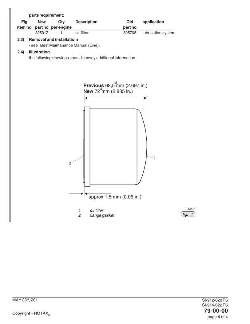
2.) Introduction of a new oil filter part no. 825012
2.1) General InformationIn the course of continous development a new oil filter has been introduced.In this connection the following modifications became necessary:- installation height of oil filter (height increased by 3,5 mm/0,138 in.)The new oil filter has been already installed on the following engines:- 912 A as of S/N 4,410.892
- 912 F as of S/N 4,412.988
- 912 S as of S/N 4,924.119
- 912 UL as of S/N 6,770.210
- 912 ULS as of S/N 6,777.866
- 914 F as of S/N 4,420.994
- 914 UL as of S/N 6,774.303
SI-912-020 R5SI-914-022 R5
79-00-00page 4 of 4
MAY 23rd, 2011
Copyright - ROTAX®
parts requirement:
Fig New Qty Description Old applicationitem no part no per engine part no
825012 1 oil filter 825706 lubrication system
2.3) Removal and installatioin- see latest Maintanance Manual (Line).
2.4) Illustrationthe following drawings should convey additional information.
062971 oil filter2 flange gasket fig. 4
12