Embed Size (px)
Citation preview
Run 2 PMG 2/16/06 - McGinnis
Run II PMGRun II PMGStacking Rapid Response Team ReportStacking Rapid Response Team Report
Dave McGinnisFebruary 16, 2006
Run 2 PMG 2/16/06 - McGinnis
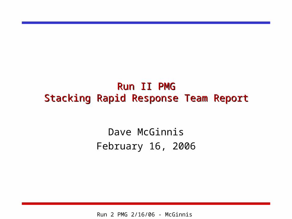
January Antiproton Study PeriodJanuary Antiproton Study Period Quad Steering of the AP1 line
Not finished Alignment of the Debuncher horizontal orbit and moveable devices.
Did not do arcs Need to Energy align the AP2-Debuncher-Accumualtor Horizontal Aperture up to 35-mm-mrad!!!
Installation and commissioning of Debuncher lattice modifications First round done Vertical aperture up to 34-mm-mrad
Removal of the Debuncher Schottkies Completed
Obstruction search of the AP2 line. Completed – none found
Installation of 4 additional AP2 trims Two trims installed Two trims staged
D/A Beam based alignment Completed to the Q3-Q6 straight section
Accumulator orbit and aperture optimization Underway Backed out of orbit changes
• Need to update quad centering software• Need to de-bug running wave software
Will only complete moveable devices
Run 2 PMG 2/16/06 - McGinnis
Returning to Stacking After the StudiesReturning to Stacking After the Studies
Production into the Debuncher was good Overall production was a function of the
amount of beam on target. Possible explanations
Spot size on target vs proton intensity Bunch length on target vs proton intensity Debuncher transverse cooling
• Far away from optimum gain• Not tripping TWT’s
Accumulator Stacktail Flux
Measure production at various places along the chain as a function of intensity on target
Run 2 PMG 2/16/06 - McGinnis
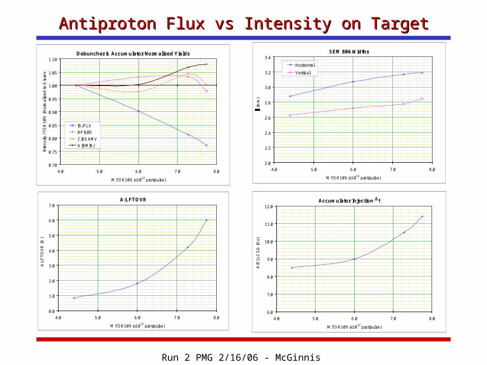
Antiproton Flux vs Intensity on TargetAntiproton Flux vs Intensity on Target
SEM 806 Widths
2.0
2.2
2.4
2.6
2.8
3.0
3.2
3.4
4.0 5.0 6.0 7.0 8.0
M:TOR109 (x1012 prot/pulse)
(m
m)
Horizontal
Vertical
Debuncher & Accumulator Normalized Yields
0.70
0.75
0.80
0.85
0.90
0.95
1.00
1.05
1.10
4.0 5.0 6.0 7.0 8.0
M:TOR109 (x1012 prot/pulse)
Inte
nsi
ty /
TO
R1
09
(N
orm
aliz
ed
to 6
turn
s)
INJFLX
BPI10D
Z:IBEAMV
A:IBMINJ
Accumulator Injection Df
6.0
7.0
8.0
9.0
10.0
11.0
12.0
4.0 5.0 6.0 7.0 8.0
M:TOR109 (x1012 prot/pulse)
A:R
1L
CS
G (
Hz)
A:LFTOVR
0.0
1.0
2.0
3.0
4.0
5.0
6.0
7.0
4.0 5.0 6.0 7.0 8.0
M:TOR109 (x1012 prot/pulse)
A:L
FT
OV
R (
%)
Run 2 PMG 2/16/06 - McGinnis
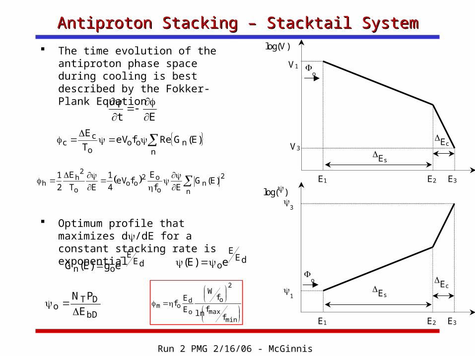
Antiproton Stacking – Stacktail SystemAntiproton Stacking – Stacktail System
The time evolution of the antiproton phase space during cooling is best described by the Fokker-Plank Equation
Optimum profile that maximizes d/dE for a constant stacking rate is exponential
log(V)
DEs
DEc
o
E1 E2 E3
V1
V3
log()
1
3
E1 E2 E3
DEs DEc
o
Et
D
n
nooo
cc )E(GRefeV
T
E
2
nn
o
o2oo
o
2h
h )E(GEf
EfeV
4
1
ET
E
2
1
D
dEE
on eg)E(G
dEE
oe)E(
bD
DTo E
PN
D
minmax
2
o
o
dom
ffln
fW
E
Ef
Run 2 PMG 2/16/06 - McGinnis
Antiproton Stacking – Stacktail SystemAntiproton Stacking – Stacktail System
The measured Accumulator 2-4 GHz Stacktail system can support a flux of 30mA/hr.
The currently used 2-4 GHz core momentum system is the same frequency as the Stacktail system At a flux of 15mA/hr, the core 2-4 GHz system can
support a exponential gain slope that is a factor of two larger than the gain slope of the Stacktail.
As the number of particles in the core increases, the factor of 2 gain slope is exceeded and the core pushes back on the Stacktail and the flux must be reduced.
For large fluxes into the Stacktail, the 2-4 GHz core momentum system cannot support a core.
Run 2 PMG 2/16/06 - McGinnis
Antiproton Stacking – Stacktail System and the Core 4-8 Antiproton Stacking – Stacktail System and the Core 4-8 GHz SystemGHz System
To support a core at high flux, the 4-8 GHz core momentum system must be used.
Because the 4-8 GHz core system runs at twice the frequency, the electrodes are ½ the size so the system has a factor of two smaller momentum reach.
Moving the core closer to Stacktail to accommodate the smaller reach resulted in system instabilities at moderate stacks.
We now : Use the 2-4 GHz core momentum system to augment
the hand-off between the Stacktail and the 4-8 GHz core momentum system
Run the 4-8 GHz core momentum system at MUCH larger gain.
Run the Stacktail during deposition debunching to pre-form the distribution to match the Stacktail profile
Run 2 PMG 2/16/06 - McGinnis
Core 4-8 GHz Momentum Cooling System Core 4-8 GHz Momentum Cooling System bandwidthbandwidth
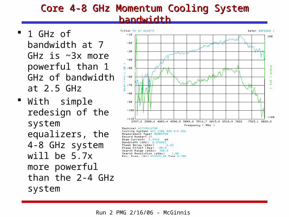
1 GHz of bandwidth at 7 GHz is ~3x more powerful than 1 GHz of bandwidth at 2.5 GHz
With simple redesign of the system equalizers, the 4-8 GHz system will be 5.7x more powerful than the 2-4 GHz system
Run 2 PMG 2/16/06 - McGinnis
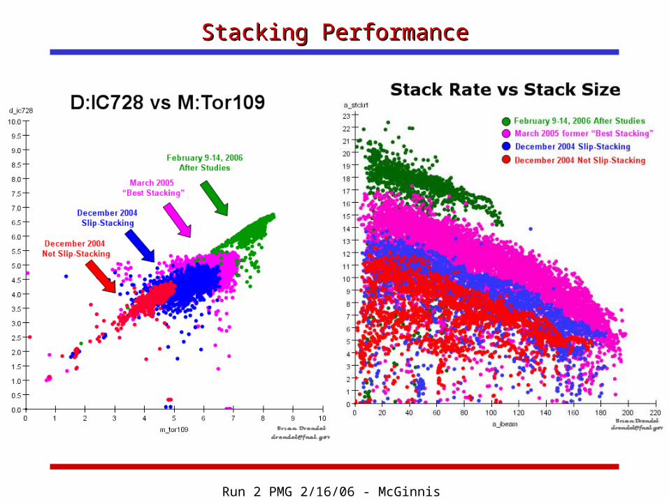
Stacking PerformanceStacking Performance
Run 2 PMG 2/16/06 - McGinnis
Antiproton ParametersAntiproton ParametersAntiproton Parameters
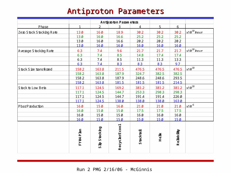
Phase 1 2 3 4 5 6
Zero Stack Stacking Rate 13.0 16.0 18.9 30.2 30.2 30.2 x10¹⁰/hour13.0 16.0 16.6 25.2 25.2 25.213.0 16.0 16.6 20.2 20.2 20.213.0 16.0 16.0 16.0 16.0 16.0
Average Stacking Rate 6.3 7.4 9.6 21.7 21.7 21.7 x10¹⁰/hour6.3 7.4 8.5 14.8 17.4 17.46.3 7.4 8.5 11.3 11.3 13.36.3 7.4 8.3 8.3 8.3 9.7
Stack Size transferred 158.2 163.8 211.5 476.5 476.5 476.5 x10¹⁰
158.2 163.8 187.9 324.7 382.5 382.5158.2 163.8 187.9 248.6 248.6 293.5158.2 163.8 181.5 181.5 181.5 214.5
Stack to Low Beta 117.1 124.5 169.2 381.2 381.2 381.2 x10¹⁰
117.1 124.5 144.7 253.3 298.3 298.3117.1 124.5 144.7 191.4 191.4 226.0117.1 124.5 138.0 138.0 138.0 163.0
Pbar Production 16.0 15.0 16.0 21.0 21.0 21.0 x10⁻⁶
16.0 15.0 15.0 17.5 17.5 17.516.0 15.0 15.0 16.0 16.0 16.016.0 15.0 15.0 15.0 15.0 15.0
FY
04
Pla
n
Slip
Sta
ck
ing
Re
cy
cle
r E
co
ol
Sta
ck
tail
He
lix
Re
liab
ility
Run 2 PMG 2/16/06 - McGinnis
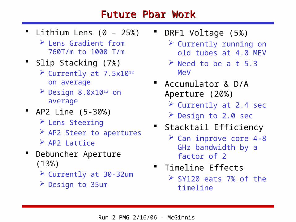
Future Pbar WorkFuture Pbar Work
Lithium Lens (0 – 25%) Lens Gradient from
760T/m to 1000 T/m Slip Stacking (7%)
Currently at 7.5x10¹² on average
Design 8.0x10¹² on average
AP2 Line (5-30%) Lens Steering AP2 Steer to apertures AP2 Lattice
Debuncher Aperture (13%) Currently at 30-32um Design to 35um
DRF1 Voltage (5%) Currently running on old
tubes at 4.0 MEV Need to be a t 5.3 MeV
Accumulator & D/A Aperture (20%) Currently at 2.4 sec Design to 2.0 sec
Stacktail Efficiency Can improve core 4-8
GHz bandwidth by a factor of 2
Timeline Effects SY120 eats 7% of the
timeline
Run 2 PMG 2/16/06 - McGinnis
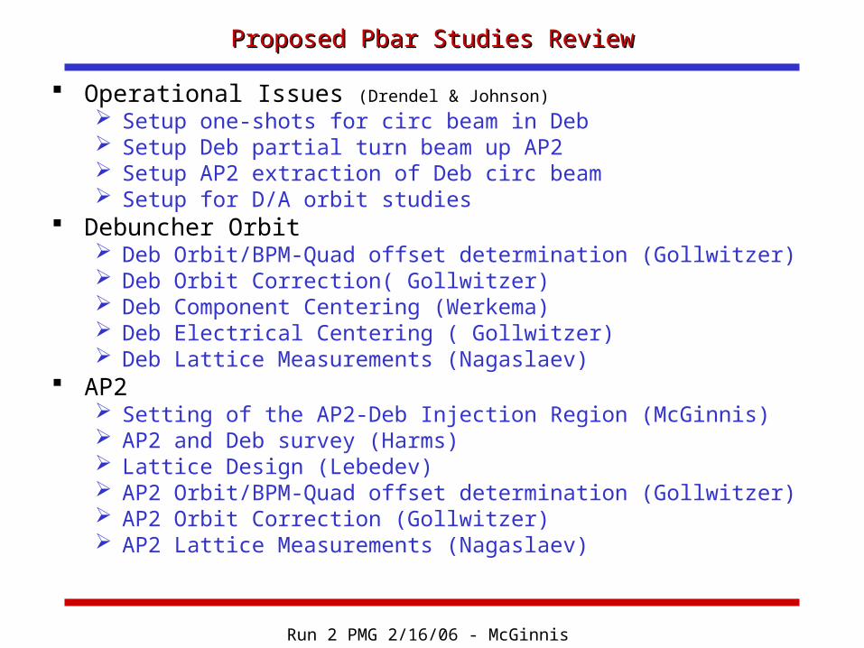
Proposed Pbar Studies ReviewProposed Pbar Studies Review
Operational Issues (Drendel & Johnson) Setup one-shots for circ beam in Deb Setup Deb partial turn beam up AP2 Setup AP2 extraction of Deb circ beam Setup for D/A orbit studies
Debuncher Orbit Deb Orbit/BPM-Quad offset determination (Gollwitzer) Deb Orbit Correction( Gollwitzer) Deb Component Centering (Werkema) Deb Electrical Centering ( Gollwitzer) Deb Lattice Measurements (Nagaslaev)
AP2 Setting of the AP2-Deb Injection Region (McGinnis) AP2 and Deb survey (Harms) Lattice Design (Lebedev) AP2 Orbit/BPM-Quad offset determination (Gollwitzer) AP2 Orbit Correction (Gollwitzer) AP2 Lattice Measurements (Nagaslaev)
Run 2 PMG 2/16/06 - McGinnis
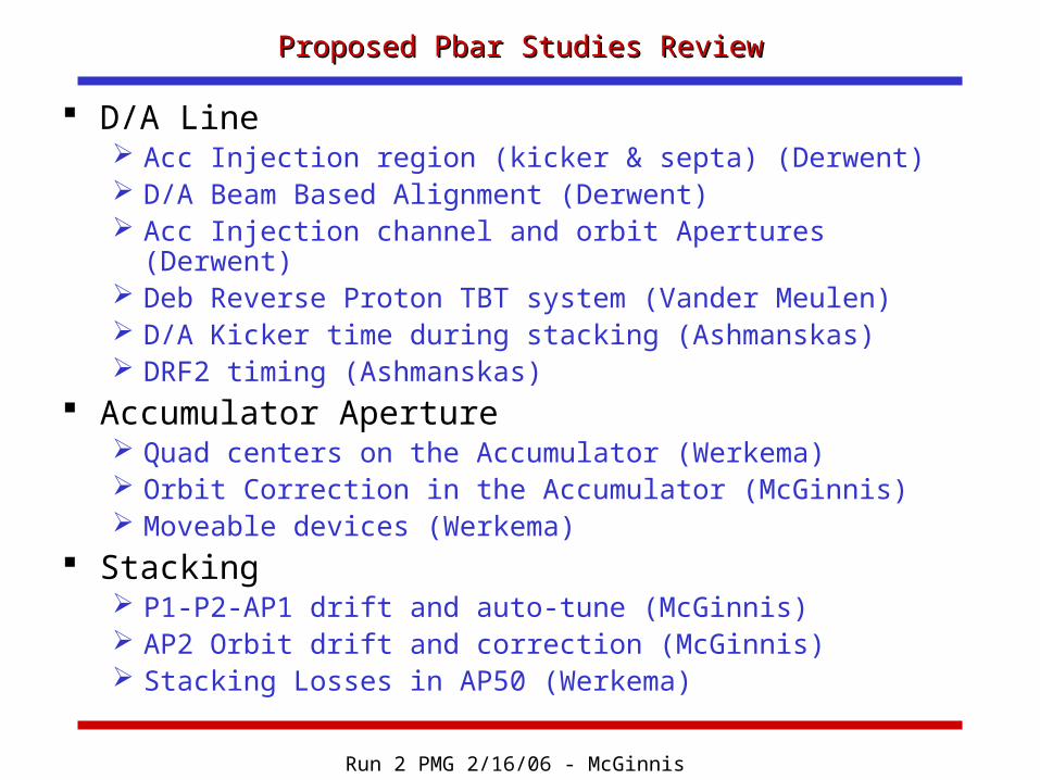
Proposed Pbar Studies ReviewProposed Pbar Studies Review
D/A Line Acc Injection region (kicker & septa) (Derwent) D/A Beam Based Alignment (Derwent) Acc Injection channel and orbit Apertures (Derwent) Deb Reverse Proton TBT system (Vander Meulen) D/A Kicker time during stacking (Ashmanskas) DRF2 timing (Ashmanskas)
Accumulator Aperture Quad centers on the Accumulator (Werkema) Orbit Correction in the Accumulator (McGinnis) Moveable devices (Werkema)
Stacking P1-P2-AP1 drift and auto-tune (McGinnis) AP2 Orbit drift and correction (McGinnis) Stacking Losses in AP50 (Werkema)