Embed Size (px)
Citation preview

Rules for Classification and Construction I Ship Technology
3 Special Craft
2 Yachts ≥ 24 m
Edition 2003

The following Rules come into force on October 1st, 2003
Germanischer Lloyd Aktiengesellschaft
Head Office Vorsetzen 35, 20459 Hamburg, Germany
Phone: +49 40 36149-0 Fax: +49 40 36149-200
www.gl-group.com
"General Terms and Conditions" of the respective latest edition will be applicable (see Rules for Classification and Construction, I - Ship Technology, Part 0 - Classification and Surveys).
Reproduction by printing or photostatic means is only permissible with the consent of Germanischer Lloyd Aktiengesellschaft.
Published by: Germanischer Lloyd Aktiengesellschaft, Hamburg Printed by: Gebrüder Braasch GmbH, Hamburg

Table of Contents
Section 1 General Requirements
A. Application, Scope ..................................................................................................................... 1- 1 B. Hull Structures ........................................................................................................................... 1- 5 C. Machinery Installations .............................................................................................................. 1- 6 D. Electrical Installations ................................................................................................................ 1- 8 E. Documents for Approval ............................................................................................................ 1- 9
Section 2 Hull Structures
A. General, Definitions ................................................................................................................... 2- 1 B. Materials, Corrosion Protection and Joining Technology .......................................................... 2- 5 C. Design Principles ....................................................................................................................... 2- 18 D. Motor und Sailing Yachts, 24 m ≤ L ≤ 48 m Steel and Aluminium Structures .......................... 2- 33 E. Motor and Sailing Yachts, 24 m ≤ L ≤ 48 m, Composite Structures .......................................... 2- 47 F. Motor und Sailing Yachts, 24 m ≤ L ≤ 48 m, Wooden Structures ............................................. 2- 57 G. Motor and Sailing Yachts, L > 48 m, Steel and Aluminium Structures ...................................... 2- 57 H. Tank Structures .......................................................................................................................... 2- 58 I. Chainplates, Ballast Keel, Propeller Brackets ............................................................................ 2- 61 J. Rudder and Manoeuvring Arrangement ..................................................................................... 2- 63 K. Anchor and Mooring Equipment ................................................................................................ 2- 77 L. Masts and Rigging ...................................................................................................................... 2- 81
Section 3 Safety Requirements
A. Safety Appliances and Provisions .............................................................................................. 3- 1 B. Structural Fire Protection ........................................................................................................... 3- 1 C. Fire Protection and Fire Extinguishing ....................................................................................... 3- 11 D. Closure Conditions, Buoyancy and Stability .............................................................................. 3- 14 E. Requirements for Hydraulically-Operated Equipment ............................................................... 3- 24 F. Requirements for Helicopter Facilities ....................................................................................... 3- 28 G. Systems for Breathing Gases and Diving ................................................................................... 3- 34
Annex A Design Loads for Yachts of High Speed Type
I - Part 3 GL 2003
Table of Contents Chapter 2Page 3

Section 1
General Requirements
A. Application, Scope
1. Application
1.1 These Rules apply to large, seagoing motor and sailing yachts with a length L ≥ 24,0 m for pri-vate, recreational use, provided that the yacht classed and approved in accordance therewith is at all times employed exclusively under the conditions for which it has been designed, constructed and approved and that it is equipped and handled in the sense of good seamanship, and operated at a speed adopted to the respective seaway conditions.
Designs which deviate from these Rules may be ap-proved, provided that such designs have been exam-ined by GL for suitability and have been recognized as equivalent.
Notes containing amendments, recommendations, etc. are always printed in italics. Other italic script in these Rules indicate matters not part of Classification.
Note
Ships with 24 m ≤ L ≤ 48 m intended for commercial purposes which do not carry more than 12 passen-gers, may be dimensioned according to Section 2, D. and E. of these Rules, taking supplementary factors into account, which have to be agreed upon with GL. The length L is defined in Section 2, A.6.
1.2 Whether and/or to which extent the GL Rules Part 1 – Seagoing Ships, Chapter 5 - High Speed Craft may have to be applied to a particular design will be decided in the individual case.
1.3 Yachts with a length 6 m ≤ LSC ≤ 24 m are covered by the GL Rules Part 3 – Special Craft, Chap-ter 3 – Yachts and Boats up to 24 m and are not sub-ject of these Rules.
2. Special aspects for yachts
Contrary to merchant ships the following aspects will usually apply regarding the operation of yachts:
– less severe operating conditions as for ships in regular trade
– limited yearly sea hours in relation to harbour hours
– special care by the owner and usually good maintenance
These Rules were developed assuming these charac-teristics.
3. Scope
3.1 The requirements of these Rules do not sub-stitute the independent judgement of professional designers. This is particularly valid for those aspects not addressed in these Rules and for which the design-ers are solely responsible.
3.2 The Rules envisage primarily technical safety matters. Aesthetical and comfort aspects, usually im-portant in yacht design, are not considered and must be subordinated to the safety requirements in conflict cases.
4. Scope of Examination/Classification ac-cording to GL Rules
4.1 Plan approval
Plan approval will only be carried out once appropri-ate and sufficient documentation has been submitted to GL.
4.2 Hull Construction Certificate
The scope of examination and construction survey related to the issuance of a Hull Construction Certifi-cate refers to the hull structure only. The hull structure has to be in compliance with the relevant scantling requirements of these Rules.
4.3 Classification
If a yacht is subject to Classification, all aspects in addition to the hull structure, i.e. machinery and elec-trical installations and ship safety matters have to be considered and must comply with the requirements of these Rules. The GL Surveyors will supervise the complete construction phase of the yacht. As Class is granted only for a limited period of time, the complete surveying procedures during service of the yacht have to be established if Class of the yacht shall be main-tained.
For more details about Classification and Class Nota-tions see GL Rules Part 0 – Classification and Sur-veys, Section 2.
I - Part 3 GL 2003
Section 1 General Requirements Chapter 2Page 1–1
A
5. Types of yachts
In addition to the Character of Classification, yachts will be characterized by Notations affixed, describing their type and envisaged use, as shown in the follow-ing examples.
SAILING YACHT
MOTOR YACHT
SPECIAL YACHT
Note
The term "special" applies to yachts of unusual shape/dimensions and with special technical equip-ment, if any. GL reserve the right of determining whether the GL Rules are applicable and how they are to be interpreted.
6. Consideration of other regulations
6.1 National regulations of various flag states
GL is prepared to include in its supervisory proce-dures the national regulations of the flag state of the yacht if the owner of the yacht wants to include this additional service and if GL is authorized by the par-ticular flag state to do so.
6.2 Regulations of the Maritime and Coast-guard Agency (MCA)
GL is prepared to consider in addition to its own Rules the regulations of the UK Maritime and Coastguard Agency if the owner of a yacht chooses this option.
7. Range of service
Yachts complying with the Construction Rule re-quirements for a restricted range of service only will have the Notations specified below affixed to their Character of Classification.
M (Restricted International Service)
This range of service is limited, in general, to voyages along the coast, provided that the distance to the near-est port of refuge and the offshore distance do not exceed 200 nautical miles. This applies also to voy-ages in the North Sea and within enclosed seas, such as the Mediterranean, the Black Sea and waters with similar conditions. Voyages to Iceland, Spitzbergen and the Azores are exempted.
K (Coastal Service) This range of service is limited, in general, to voyages along the coasts, provided that the distance to the nearest port of refuge and the offshore distance do not exceed 50 nautical miles. This applies also to voyages within enclosed seas such as the Baltic Sea and gulfs with similar seaway conditions.
Where a permissible distance of less than 50 nautical miles has been fixed for a yacht, the relevant distance will be added in brackets behind the Notation K in the Class Certificate, e.g. K(20).
W (Sheltered Water Service) This range of service is limited to voyages in shoals, bays, haffs and firths or similar waters, where heavy seas do not occur.
The Notations may possibly be assigned on the basis of the seaway conditions prevailing in the respective service area (e.g. official seaway statistics).
Observance of the range of service boundaries is a prerequisite for validity of the Class.
GL may, on application, agree to the range of service being extended for a limited period and/or with certain reservations. This will have to be documented.
8. Ambient conditions
8.1 General operating conditions
The selection, layout and arrangement of the yacht's structure and all shipboard machinery, equipment and appliances shall be such as to ensure unobstructed continuous operation under the ambient conditions specified in these Rules.
8.2 Inclinations and movements of the yacht
The design limits for yacht inclinations and move-ments are defined in Table 1.1.
Account is to be taken of the effects of distortion of the yacht's hull on the machinery installations.
8.3 Environment of the yacht
The design environmental conditions of a yacht are defined in Table 1.2.
9. Vibrations and noise
Vibrations are defined as structural oscillations in the frequency range of 1 Hz to 80 Hz. Noise is defined as audible air pressure variations, generated for instance by main engines and propellers, auxiliary machinery, equipment and persons within the frequency range of 16 Hz to 16 000 Hz.
Chapter 2 Page 1–2
Section 1 General Requirements I - Part 3GL 2003
A
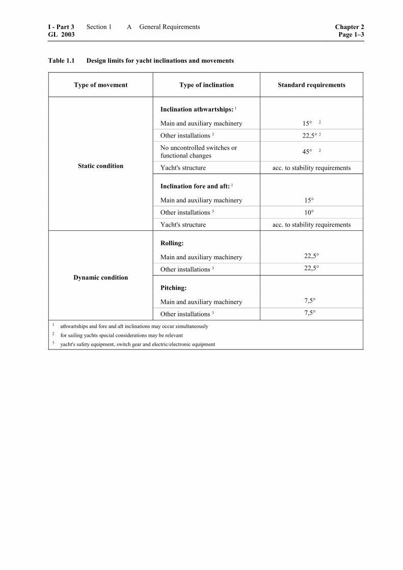
Table 1.1 Design limits for yacht inclinations and movements
Type of movement Type of inclination Standard requirements
Inclination athwartships: 1
Main and auxiliary machinery 15° 2
Other installations 3 22,5° 2
No uncontrolled switches or functional changes 45° 2
Yacht's structure acc. to stability requirements
Inclination fore and aft: 1
Main and auxiliary machinery 15°
Other installations 3 10°
Static condition
Yacht's structure acc. to stability requirements
Rolling:
Main and auxiliary machinery 22,5°
Other installations 3 22,5°
Pitching:
Main and auxiliary machinery 7,5°
Dynamic condition
Other installations 3 7,5° 1 athwartships and fore and aft inclinations may occur simultaneously 2 for sailing yachts special considerations may be relevant 3 yacht's safety equipment, switch gear and electric/electronic equipment
I - Part 3 GL 2003
Section 1 General Requirements Chapter 2Page 1–3
A
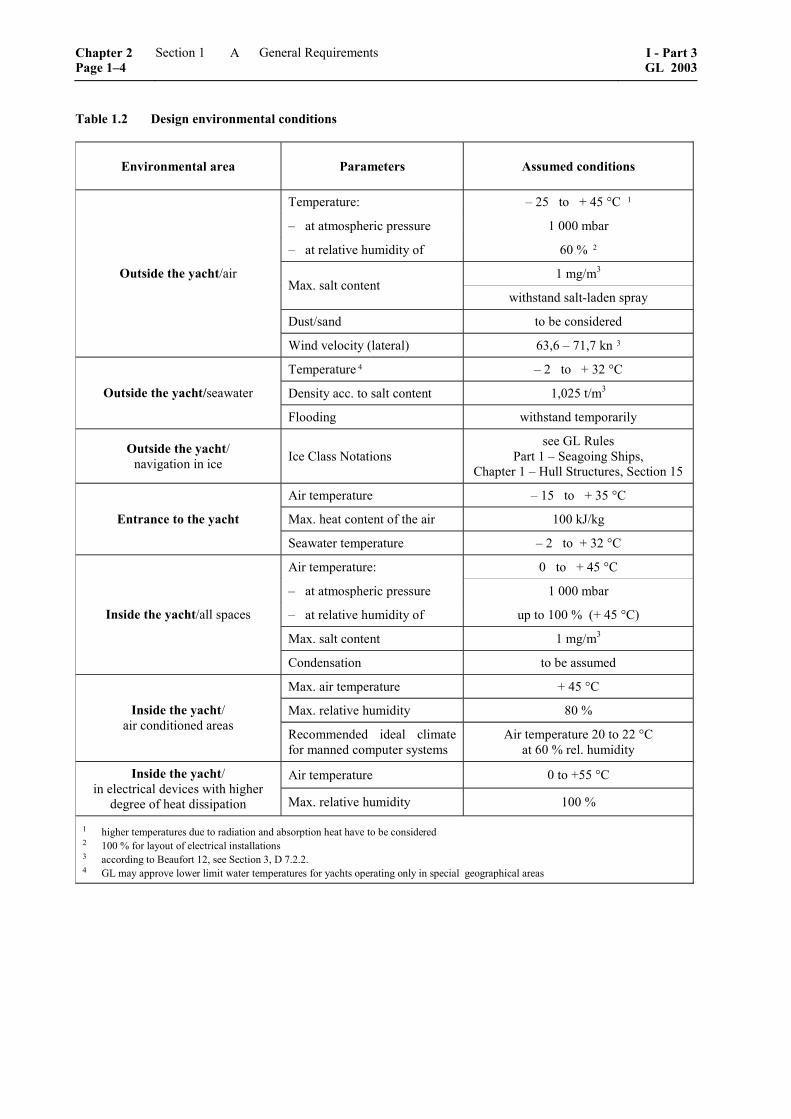
Table 1.2 Design environmental conditions
Environmental area Parameters Assumed conditions
Temperature: – 25 to + 45 °C 1
– at atmospheric pressure 1 000 mbar
– at relative humidity of 60 % 2
1 mg/m3 Max. salt content
withstand salt-laden spray
Dust/sand to be considered
Outside the yacht/air
Wind velocity (lateral) 63,6 – 71,7 kn 3
Temperature 4 – 2 to + 32 °C
Density acc. to salt content 1,025 t/m3 Outside the yacht/seawater
Flooding withstand temporarily
Outside the yacht/ navigation in ice Ice Class Notations
see GL Rules Part 1 – Seagoing Ships,
Chapter 1 – Hull Structures, Section 15
Air temperature – 15 to + 35 °C
Max. heat content of the air 100 kJ/kg Entrance to the yacht
Seawater temperature – 2 to + 32 °C
Air temperature: 0 to + 45 °C
– at atmospheric pressure 1 000 mbar
– at relative humidity of up to 100 % (+ 45 °C)
Max. salt content 1 mg/m3
Inside the yacht/all spaces
Condensation to be assumed
Max. air temperature + 45 °C
Max. relative humidity 80 % Inside the yacht/ air conditioned areas
Recommended ideal climate for manned computer systems
Air temperature 20 to 22 °C at 60 % rel. humidity
Air temperature 0 to +55 °C Inside the yacht/ in electrical devices with higher
degree of heat dissipation Max. relative humidity 100 %
1 higher temperatures due to radiation and absorption heat have to be considered 2 100 % for layout of electrical installations 3 according to Beaufort 12, see Section 3, D 7.2.2. 4 GL may approve lower limit water temperatures for yachts operating only in special geographical areas
Chapter 2 Page 1–4
Section 1 General Requirements I - Part 3GL 2003
A
9.1 Vibrations
9.1.1 On board yachts vibration may become im-portant with respect to the following issues:
– annoyance of owner, passenger or crew
– functioning of electronic devices, main and auxiliary machinery
– integrity of structures
9.1.2 It is recommended that in the building speci-fication maximum vibration levels are agreed on. If desired, GL can give guidance in this respect.
9.1.3 It is recommended that theoretical investiga-tions will be performed from an early design stage in order to identify critical points of the individual de-sign. If desired, GL can give guidance in this respect.
9.1.4 Electric or electronic devices relevant for the ship's safety and functionality have to withstand the vibration loads as defined by type testing procedures in Part 1 – Seagoing Ships, Chapter 3 – Electrical Installations, Section 1, Table 1.4.
9.1.5 Masts shall be constructed in such a way that no resonance of basic vibration modes with relevant excitation frequencies is present. The mast foundation shall be constructed as stiff as possible.
9.1.6 Vibration may damage machinery or equip-ment. Vibration can be self-excited, as in the case of propulsion machinery, or is caused by excitation from its foundation. In any case machinery and equipment shall withstand vibration loads without loss of in-tended function.
9.1.7 Vibration limits regarding reciprocating main engines and auxiliary machinery are defined in Part 1 – Seagoing Ships, Chapter 2 – Machinery In-stallations, Section 1, C.2.
9.1.8 The main tuning frequencies of resilient ma-chinery supports must be compared to the relevant excitation frequencies which occur on the individual ship. The properties of the mounting elements must be chosen in such a way that the safety margin between those frequencies is sufficient.
9.1.9 Excessive vibration may damage the ship's structure. Therefore, it has to be ensured that local structures in vicinity of the propellers or the main machinery are not vibrating in resonance with one of the relevant excitation frequencies created by the propeller or other machinery.
9.2 Noise
Suitable precautions are to be taken to keep specified sound level limits, particularly in the owner and guest accommodations, crew quarters, etc.
Regarding crew's quarters the IMO code on noise levels on board ships may be taken as guidance. Sound level limits for owner and guest spaces should be agreed on between owner and yard.
If requested by the yard and/or owner GL is prepared to carry out a noise review in the pre-contract or early design state as well as reviewing the building specifi-cation with reference to noise matters.
Further services e.g. detailed noise prediction, noise measurements, acoustic factory tests, etc. can also be provided by GL upon request.
B. Hull Structures
1. Special requirements for yachts
The requirements for the hull structures and the re-lated equipment are defined in Section 2.
2. Relevant other GL Rules and Guidelines
For the design of the hull structure the following other Rules for Classification and Construction of Ger-manischer Lloyd will mainly be referred to:
– I – Ship Technology Part 0 – Classification and Surveys
– I – Ship Technology Part 1 – Seagoing Ships Chapter 1 – Hull Structures
– I – Ship Technology Part 1 – Seagoing Ships Chapter 5 – High Speed Craft
– I – Ship Technology Part 4 – Special Equipment Chapter 2 – Rigging Design
– I – Ship Technology Part 4 – Special Equipment Chapter 5 – Guidelines for the Design and Con-
struction of Large Modern Yacht Rigs
– I – Schiffstechnik Teil 1 – Seeschiffe Kapitel 13 – Vorschriften für Klassifikation und
Bau von hölzernen Seeschiffen 1
–––––––––––––– 1 Translation: "Rules for Classification and Construction of
Wooden Seagoing Ships" (not available in Eng-lish)
I - Part 3 GL 2003
Section 1 General Requirements Chapter 2Page 1–5
B
– II – Materials and Welding
Part 1 – Metallic Materials
– II – Materials and Welding
Part 2 – Non-metallic Materials
Chapter 1 – Fibre Reinforced Plastics and Adhe-sive Joints
– II – Materials and Welding
Part 2 – Non-metallic Materials
Chapter 2 – Wood
– II – Materials and Welding,
Part 3 – Welding
– VI – Additional Rules and Guidelines
Part 2 – Lifting Appliances
Chapter 2 – Guidelines for the Construction and Survey of Lifting Appliances
C. Machinery Installations
1. General
On principle yachts shall meet the requirements of Part 1 – Seagoing Ships, Chapter 2 – Machinery In-stallations for "cargo ships" as far as applicable.
The exceptions from this principle and/or special, deviating requirements for yachts are defined in the following.
2. Special requirements for yachts
2.1 General rules and instructions
2.1.1 Ambient and general operating conditions
The conditions are defined in A.8. Special attention shall be given to the operating conditions of sailing yachts.
2.1.2 Propulsion plant, turning appliances
Turning appliances for main engines need not be pro-vided unless specified by the engine manufacturers as standard.
Yachts with more than one propulsion system shall be equipped with shaft brakes unless the gearbox is de-signed for operation under trolling conditions or an independent trolling pump is fitted. All propulsion systems of sailing yachts with non-declutchable pro-peller shafts/gearboxes shall have a shaft brake.
3. Main shafting
3.1 Shaft dimensions, minimum diameter
For determining the minimum shaft diameter the fac-tor F for the type of propulsion installation may be taken as F = 95 and the actual tensile strength Rm shall be used for calculating the material factor Cw, see Part 1 – Seagoing Ships, Chapter 2 – Machinery Installa-tions, Section 4, C.2.
3.2 Temperature indication
An indication of the temperature of the stern tube bearing or of the lubrication oil need not to be pro-vided for yachts of a length L ≤ 48 m.
4. Gears, couplings
The minimum safety margins for endurance limits for contact stress and percentage area of contact as de-fined in Tables 5.4 and 5.6 Part 1 – Seagoing Ships, Chapter 2 – Machinery Installations, Section 5 shall be applied.
5. Propeller
5.1 Controllable pitch propellers, indicators
Controllable pitch propeller systems are to be pro-vided with a mechanical indicator at the controls in the engine room, showing the actual setting of the blades. Further blade setting indicators are to be provided on the bridge.
5.2 Balancing
The finished propeller and the blades of controllable pitch propellers are required to undergo static balanc-ing. For propeller revolutions above 500 rpm also dynamic balancing is recommended.
6. Steam boilers, pressure vessels
For yachts of a length L ≤ 48 m all equipment under pressure shall be in accordance with a recognized standard. For yachts of a length L > 48 m the pressure equipment has to meet the GL Rules Part 1 – Seagoing Ships, Chapter 2 – Machinery Installations, Section 7a and 8.
7. Pipes, valves, fittings and pumps
7.1 Testing of materials
For yachts of a length L ≤ 48 m, material certificates 3.1.B according to DIN EN 10204 for fittings and valves in pipe classes I and II may be provided.
Chapter 2 Page 1–6
Section 1 General Requirements I - Part 3GL 2003
C
7.2 Oil fuel systems, filters
Any internal combustion engine, regardless of its intended use, shall be equipped with duplex type water separators incorporating pre-filter elements. Changing of filter elements and draining of the separator shall be possible with the engine operating.
7.3 Service tanks
For motor yachts of a length L ≤ 48 m and all sailing yachts fuel oil service tanks need not be provided.
7.4 Lubricating oil system
For internal combustion engines single lubricating oil filters are acceptable for sailing yachts and motor yachts with more than one propulsion engine.
7.5 Lubricating oil pumps, main engines
Yachts for restricted service or with more than one main propulsion system need not have redundant lubricating pumps. Yachts for unrestricted service and with a single propulsion plant shall have a redundant lubricating pump or carry on board a spare lubricating pump.
7.6 Bilge systems
7.6.1 Calculation of pipe diameters
7.6.1.1 Main bilge pipes
The diameter dH of the bilge main shall be calculated according to the following formula. The actual inside diameter of the bilge main shall be rounded to the next higher nominal standard:
( )Hd 25 1,68= + +L B H
dH = the calculated inside diameter of the main bilge pipe [mm]
L = the length of the yacht [m] as defined in Section 2, A.6.
B = for monohull yachts, the breadth of the yacht in [m] as defined in Section 2, A.6.; for mul-ti-hull yachts the breadth of one hull at the design waterline [m]
H = the moulded depth of the yacht [m] as de-fined in Section 2, A.6.
7.6.1.2 Branch bilge pipes
The inside diameter is given by the formula:
( )zd 25 2,15= + +B H
dz = calculated inside diameter [mm] of the branch pipes
= length [m] of the watertight compartment
7.6.1.3 Minimum diameter
The inside diameter of main and branch bilge pipes is not to be less than 50 mm. For yachts with L ≤ 48 m, the inside diameter may be reduced to 40 mm.
7.6.2 Bilge pumps
The number of bilge pumps is to be evaluated as pre-scribed for cargo ships.
7.6.3 Bilge pumping for various spaces
7.6.3.1 Machinery spaces
On yachts of more than 100 gross tons, the bilges of every machinery space must be capable of being drained as follows:
– through the bilge suctions connected to the main bilge system
– through one direct suction connected to the largest independent bilge pump
– through an emergency bilge suction connected to the independent cooling water pump of the main propulsion plant or through another suit-able emergency bilge system
For yachts with a length L ≤ 48 m inclusive, the emergency bilge suction need not be provided, if an independent power driven sea water cooling pump or any other suitable pump is not available.
7.6.3.2 Bilge suctions for other spaces
Bilge suction is to be arranged for the shaft tunnel (if applicable), fore and after peaks, cofferdams, pipe tunnels and void spaces as well as chain lockers.
7.6.4 Bilge testing
For yachts with a length L above 48 m all bilge ar-rangements are to be tested under GL supervision.
7.6.5 Equipment for the treatment and storage of bilge water, fuel and oil residues
7.6.5.1 Oily water separating equipment
Note
Also for yachts of less than 400 gross tons it is not permitted to discharge oily bilge water as well as fuel and oil residues into the sea 2. It is therefore recom-mended to provide also for such yachts equipment for collecting these liquids and to discharge them to re-ception facilities.
–––––––––––––– 2 With regard to the installation on yachts of oily water separa-
tors, filter plants, oil collecting tanks, oil discharging lines and a 15 ppm alarm device in the water outlet of oily water separa-tors, compliance is required with the provisions of the Interna-tional Convention for the Prevention of Pollution from Ships, 1973 (MARPOL) and the Protocol 1978, as applicable.
The GL form F 323 (MP1) is to be submitted for approval, if a IOPP certificate is applied for.
I - Part 3 GL 2003
Section 1 General Requirements Chapter 2Page 1–7
C
7.7 Cooling systems
All internal and external cooling systems of any inter-nal combustion engine have to be in compliance with the manufacturer's installation recommendation.
If the manufacturers recommend coolant treatment and checks, the design of the piping system has to be such, that applying of additives and taking of samples is easily possible. All coolant venting lines have to be arranged with upwards slope throughout.
7.8 Seawater cooling system, sea chests
For motor yachts of a length L ≤ 48 m and all sailing yachts a second sea chest need not be provided.
7.9 Clearing sea chest gratings
All sailing yachts need not be provided with a device for sea chest clearing. Motor yachts with an auxiliary system producing compressed air shall be equipped with means for clearing sea chests.
7.10 Seawater cooling pumps, diesel engine plants
Yachts for unrestricted service and a single propulsion plant should have a stand-by seawater pump or carry a spare seawater pump on board. If feasible, the same applies to internal coolant circuit water pumps. At least one repair kit per each seawater pump type has to be carried on board.
Yachts for restricted service or with more than one main propulsion system need not have stand-by sea-water cooling pumps.
7.11 Air, overflow and sounding pipes
Each tank is to be fitted with air pipes, overflow and sounding pipes. The air pipes are in general to be led to above the exposed deck. The height from the deck to the point where the water may have access is to be at least 760 mm on the freeboard deck and 450 mm on a superstructure deck. These heights may be reduced in agreement with GL if the point of water access is suitably arranged.
Suitable closing appliances are to be provided for these pipes. For air pipes of 32 mm in diameter and above automatic closures are to be provided. In yachts for which flooding calculations are to be made, the ends of the air pipes are to be above the damage wa-terline in the flooded condition. Where they immerse at intermediate stages of flooding, these conditions are to be examined separately.
Sounding pipes are to be extended to directly above the tank bottom. Striking plates have to be provided under the sounding pipes.
8. Steering gears, hydraulic control systems
A hydraulic locking alarm shall be provided to indi-cate failure of single control components.
9. Operating instructions, tools, spare parts
9.1 Operating instructions
All necessary operating and maintenance instructions as well as spare parts lists recommended by the manu-facturers of machinery and ancillary equipment shall be available on board.
9.2 Tools
Sufficient tools are to be carried to allow for repair or maintenance work to be carried out as described in the operating and maintenance instructions. Scope of maintenance (and subsequently tooling) necessary will be subject to the range of service and the type of the yacht.
9.3 Spare parts
If extended voyages of yachts are intended, it is the operator's responsibility to carry on board additional tools, accessories, consumables and spares in accor-dance with the recommendations of the en-gine/component manufacturers and with the foresee-able needs and/or availability conditions during the particular voyage.
10. Fire protection and fire extinguishing equipment
This equipment is defined in Section 3, C.
D. Electrical Installations
1. General
For the electrical installations of large yachts no spe-cial rules and guidelines are contained in these Rules. The already existing international standards and GL Rules as defined below shall be used, as applicable.
In particular, justified cases deviations from these requirements may be accepted by GL on special re-quest.
2. Special requirements for yachts with L ≤ 48 m
For all types of yachts with a length L ≤ 48 m the following International Standard has to be applied:
– International Electrotechnical Commission IEC 60092 – Part 507: "Electrical installations in ships – Pleasure craft".
Chapter 2 Page 1–8
Section 1 General Requirements I - Part 3GL 2003
D

This standard is valid for unrestricted service and all other ranges of service.
Note
This part of IEC 60092 incorporates and coordinates, as far as possible, existing requirements for electrical installations relevant to pleasure craft as published in other parts of the IEC 60092 series, the publications of ISO technical committee 188 and the IEC 60364 series.
The first edition of this standard has been issued 2000-02 and the committee has decided that the con-tents of publication will remain unchanged until 2005-06.
3. Special requirements for yachts with L > 48 m
For all types of yachts with a length L > 48 m the following GL Rules have to be applied:
– Part 1 – Seagoing Ships
Chapter 3 – Electrical Installations
– Part 1 – Seagoing Ships
Chapter 4 – Automation
E. Documents for Approval
1. General requirements
1.1 All documents have to be submitted to GL in German or English language.
1.2 The survey of the yacht's construction will be carried out on the basis of approved documents. The drawings must contain all data necessary for assess-ment and approval. Where deemed necessary, calcula-tions and descriptions of the yacht's elements are to be submitted. Any non-standard symbols used are to be explained in a key list. All documents must show the number of the project and the name of the owner and/or shipyard.
1.3 Submitted calculations shall contain all nec-essary information concerning reference documents, literature and other sources.
The calculations have to be compiled in a way which allows to identify and check all steps. Handwritten, easily readable documents are acceptable.
Where appropriate, results of calculations shall be presented in graphic form. A written comment to the main conclusions resulting from the calculations has to be provided.
1.4 GL reserve the right to demand additional documentation if that submitted is insufficient for an assessment of the ship or essential parts thereof. This may especially be the case for plants and equipment related to new developments and/or which are not tested on board to a sufficient extent.
1.5 The drawings are to be submitted at least in triplicate, all calculations and supporting documenta-tion in one copy for examination at a sufficiently early date to ensure that they are approved and available to the Surveyor at the beginning of the manufacture of the ship or the installation of important components.
1.6 Once the documents submitted have been approved by GL they are binding on the execution of the work. Subsequent modifications and extensions require the approval of GL before becoming effective.
2. Guidance for submission of documents
2.1 Upon request the list of required documents for classification will be provided by GL.
2.2 An excerpt of this list confined to examina-tion of the hull structure regarding issuance of a Hull Construction Certificate is given in the following.
List of Documents to be submitted for the Exami-nation Scope "Hull Construction Certificate"
As far as applicable for an individual yacht the follow-ing documents have to be submitted:
– Hull structural drawings
– General Arrangement Plan
– Lines Plan
– Deck Layout
– Main Particulars (including LH, LWL, B, BWL, H, T, Δ, v0)
– Tank Arrangement Plan
– Specification of Construction Materials
– Shell Expansion and Specification of Welded Joints for Metal Hulls
– Hull Lay-up Plan and Secondary Bonding of Structural Members for Composite Hulls
– Locations and Size of Openings in the Hull Shell
– Bulkheads (transverse, longitudinal and wash bulkheads, tank boundaries including posi-tions of overflow)
– Longitudinal Section (longitudinal and trans-verse hull structure, location of watertight bulkheads, tank boundaries, deck supporting structures)
I - Part 3 GL 2003
Section 1 General Requirements Chapter 2Page 1–9
E
– Midship Section (longitudinal and transverse hull structure, details of anchoring and moor-ing equipment)
– Typical Cross Sections of the Aft and Fore End Area
– Bottom Structure (longitudinal and transverse structure, watertight subdivision of double bottom, if applicable)
– Engine Room Structure (including main engine foundation)
– Decks (scantling of deck structures, pillars, location of openings)
– Bulwark Plating and Structure
– Superstructures (plating, structural members and support of superstructures like bulkheads and pillars, openings)
– Propeller Brackets and Shaft Exits, if appli-cable
– Bow Thruster, if applicable
– Windlass and Chain Stopper Seating (includ-ing substructure and details on loads to be transmitted)
– Typical Structural Details
– Rudder
– Steering Arrangement (if applicable waterjet arrangement)
– Structure of the Rudder Body
– Rudder Horn and Structural Integration, if applicable
– Position and Specification of Rudder Bear-ings
– Rudder Stock and Material Specification
– Rudder Bearing Seats
– Keel of sailing yachts
– Bottom Structure in Way of the Ballast Keel Attachment to the Hull
– Keel Geometry, Weight and Centre of Grav-ity
– Keel Root and other Relevant Cross Sections of the Ballast Keel Structure
– Details of the Keel's Structural Attachment to the Hull
– Chain plates of sailing yachts
– Sail Plan and Size of Standing Rigging
– Hull Structure in Way of Mast Step and Chain plates
– Details of all Chain plates including Struc-tural Attachment to the Hull
Chapter 2 Page 1–10
Section 1 General Requirements I - Part 3GL 2003
E

Section 2
Hull Structures
A. General, Definitions
1. Notations
1.1 Restricted service ranges
For determining the scantlings of the longitudinal and transverse structures of yachts intended to operate within one of the restricted service ranges M, K(50), K(20), and W according to Section 1, A.7., the design loads may be reduced as specified in the particular case.
1.2 Strengthening for navigation in ice
For yachts with 24 m ≤ L ≤ 48 m additional require-ments have to be agreed upon with GL in each indi-vidual case.
For yachts with L > 48 m reference is made to the GL Rules Part 1 – Seagoing Ships, Chapter 1 – Hull Structures, Section 15.
1.3 Further notations
Further Class Notations are given in Part 0 – Classi-fication and Surveys.
2. Equivalence
Yachts deviating from the GL Rules for Construction and Classification in their type, equipment or in some other parts may be classed, provided that their struc-tures or equipment is found to be equivalent to GL's requirements for the respective class.
3. Ambient conditions
The ambient conditions including inclinations and movements of the yacht, its environment as well as vibrations and noise to be experienced are described in Section 1, A.8. and A.9.
4. Accessibility
All parts of the hull shall be accessible for survey and maintenance, as far as feasible.
5. Stability
The requirements for stability of yachts are defined in Section 3, D.
6. Definitions
6.1 General
Unless noted otherwise, the dimensions according to 6.2 and 6.3 are to be inserted in [m] into the formulae stated in the following.
6.2 Principal dimensions
6.2.1 Length L
The length L of the yacht is the distance on the water-line at full displacement, from the fore side of the stem to the centre of the rudder stock. L is not to be less than 96 % and need not to be greater than 97 % of the extreme length of the full displacement waterline. In yachts with unusual stern and bow arrangement, the length L will be specially considered.
6.2.2 Length Lc (according to LLC 66, MARPOL 73/78, IBC-Code and IGC-Code)
The length Lc is to be taken as 96 % of the total length on a waterline at 85 % of the least moulded depth Hc , measured from the top of the keel, or as the length from the foreside of the stem to the axis of the rudder stock on that waterline, if that be greater. In yachts designed with a rake of keel the waterline on which this length is measured shall be parallel to the design waterline.
For the definition of the least moulded depth Hc see LLC 66, Annex I, Chapter I, Regulation 3(5).
6.2.3 Length L* (according to SOLAS 74, Chap-ter II-1, Reg. 2)
The length L* of the yacht is the length measured between perpendiculars taken at the extremities of the deepest subdivision loadline.
6.2.4 Subdivision length Ls
Reference is made to the definition in SOLAS 74, Chapter II-1, Reg.25 – 2.2.1.
6.2.5 Forward perpendicular FP
The forward perpendicular coincides with the foreside of the stem on the waterline on which the respective length L, Lc, L* is measured.
I - Part 3 GL 2003
Section 2 Hull Structures Chapter 2Page 2–1
A
6.2.6 Aft perpendicular AP
The aft perpendicular coincides with a point at the distance L aft of FP.
6.2.7 Breadth B
The breadth B is the greatest moulded breadth of the yacht.
Note
The moulded breadth depends on the construction material of the hull:
– steel and aluminium hull: referring to inner edge of the shell
– all other materials: referring to outer edge of the shell
The term "moulded" applies for other dimensions accordingly.
6.2.8 Depth H
The depth H is the vertical distance, at the middle of the length L, from the base line to top of the deck beam at side on the uppermost continuous deck.
In way of effective superstructures, the depth is to be measured up to the superstructure deck for determin-ing the yacht's scantlings.
6.2.9 Draught T
The draught T is the vertical distance, at the middle of the length L, from base line to full displacement wa-terline.
6.2.10 Hull draught TH
The hull draught TH is the maximum draught of the canoe body of the yacht.
6.3 Frame spacing a
The frame spacing a will be measured from moulding edge to moulding edge of frames.
6.4 Block coefficient CB
Moulded block coefficient at full displacement draught T, based on the rule length L:
BC ∇=
⋅ ⋅L B T
∇ = moulded volume up to the full displacement waterline [m³]
6.5 Yacht's speed v0
The yacht's speed v0 [kn] is the expected maximum ahead speed of the yacht in calm water, at the full displacement waterline.
6.6 Moulded displacement Δ
The moulded displacement Δ is the weight of the yacht [t] at draught T.
6.7 Definition of decks
6.7.1 Bulkhead deck
Bulkhead deck is the deck up to which the watertight bulkheads are carried.
6.7.2 Freeboard deck
Freeboard deck is the deck upon which the freeboard calculation is based.
6.7.3 Strength deck Strength deck is the deck or the parts of a deck which form the upper flange of the effective longitudinal structure.
6.7.4 Weather deck All free decks and parts of deck exposed to the sea are defined as weather decks.
6.7.5 Shelter deck Decks which are not accessible to guests and which are not subject to sea pressure. Crew can access such deck with care and taking account of the admissible load, which is to be clearly indicated.
6.7.6 Accommodation deck Accommodation deck is a deck which is not exposed to the sea and serves as a basis for usual crew or guest accommodation.
6.7.7 Superstructure deck The superstructure decks situated immediately above the uppermost continuous deck are termed forecastle deck, bridge deck and poop deck.
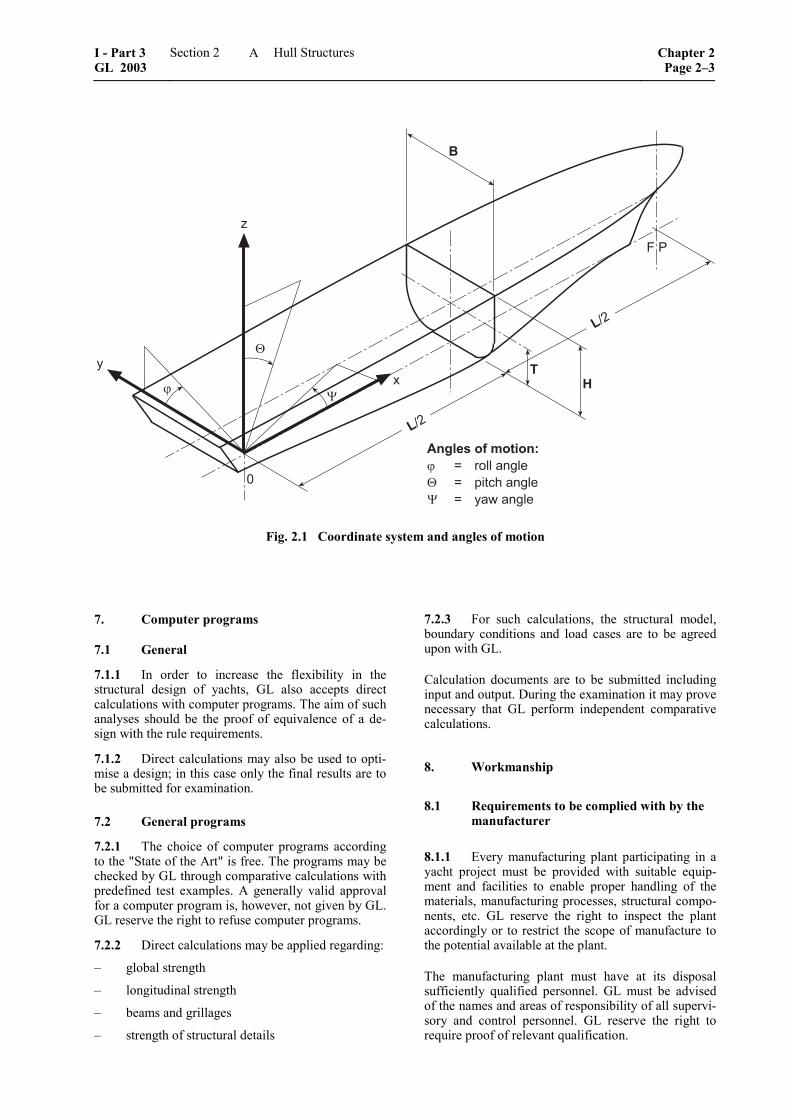
6.8 Coordinate system
For the description of the yacht's geometry the fixed, right-handed coordinate system 0, x, y, z as defined in Fig. 2.1 is introduced. The origin of the system is situated at the aft perpendicular, at centreline and on the moulded baseline at the yacht's keel. The x-axis points in longitudinal direction of the yacht positive forward, the y-axis positive to port and the z-axis positive upwards. Angular motions are considered positive in a clockwise direction about the three axes.
Chapter 2 Page 2–2
Section 2 Hull Structures I - Part 3GL 2003
A
�
��
�
�
�
���
��
�������� ���� �� ���� �� ��������� �� ������� �
��
�
�
��
Fig. 2.1 Coordinate system and angles of motion
7. Computer programs
7.1 General
7.1.1 In order to increase the flexibility in the structural design of yachts, GL also accepts direct calculations with computer programs. The aim of such analyses should be the proof of equivalence of a de-sign with the rule requirements.
7.1.2 Direct calculations may also be used to opti-mise a design; in this case only the final results are to be submitted for examination.
7.2 General programs
7.2.1 The choice of computer programs according to the "State of the Art" is free. The programs may be checked by GL through comparative calculations with predefined test examples. A generally valid approval for a computer program is, however, not given by GL. GL reserve the right to refuse computer programs.
7.2.2 Direct calculations may be applied regarding:
– global strength
– longitudinal strength
– beams and grillages
– strength of structural details
7.2.3 For such calculations, the structural model, boundary conditions and load cases are to be agreed upon with GL.
Calculation documents are to be submitted including input and output. During the examination it may prove necessary that GL perform independent comparative calculations.
8. Workmanship
8.1 Requirements to be complied with by the manufacturer
8.1.1 Every manufacturing plant participating in a yacht project must be provided with suitable equip-ment and facilities to enable proper handling of the materials, manufacturing processes, structural compo-nents, etc. GL reserve the right to inspect the plant accordingly or to restrict the scope of manufacture to the potential available at the plant.
The manufacturing plant must have at its disposal sufficiently qualified personnel. GL must be advised of the names and areas of responsibility of all supervi-sory and control personnel. GL reserve the right to require proof of relevant qualification.
I - Part 3 GL 2003
Section 2 Hull Structures Chapter 2Page 2–3
A
8.1.2 The shipyard or manufacturing plant and its subcontractors must get approval from GL for the type of work provided for the manufacture and installation of yachts. Approval can only be awarded if the condi-tions defined in detail in the GL Rules II – Materials and Welding are fulfilled.
8.1.3 The fabrication sites, stores and their opera-tional equipment shall comply also with the require-ments of the relevant Safety Authorities and Profes-sional Associations. The shipyard or manufacturing plant is alone responsible for compliance.
8.2 Quality control
8.2.1 It is recommended that the shipyard operates a quality assurance system, like ISO 9001 or equiva-lent.
8.2.2 As far as required and expedient, the manu-facturer’s personnel has to examine all structural com-ponents both during the manufacture and on comple-tion, to ensure that they are complete, that the dimen-sions are correct and that workmanship is satisfactory and meets the standard of good shipbuilding practice.
8.2.3 Upon inspection and corrections by the manufacturing plant, the structural components are to be shown to the GL Surveyor for inspection, in suit-able sections, normally in unpainted condition and enabling proper access for inspection.
8.2.4 The Surveyor may reject components that have not been adequately checked by the plant and may demand their re-submission upon successful completion of such checks and corrections by the plant.
9. Structural details
9.1 Details in manufacturing documents
9.1.1 All significant details concerning quality and functional ability of the components concerned shall be entered in the manufacturing documents (workshop drawings, etc.). This includes not only scantlings but, where relevant, such items as surface conditions (e.g. finishing of flame cutting edges and weld seams), and special methods of manufacture involved as well as inspection and acceptance requirements and, where relevant, permissible tolerances.
For details of welded joints see the GL Rules II – Ma-terials and Welding, Part 3 – Welding, Chapter 2 – Design, Fabrication and Inspection of Welded Joints, Annex A (Steel) and B (Aluminium).
For details of adhesive joints see the GL Rules II –Materials and Welding, Part 2 – Non-metallic Materi-als, Chapter 1 – Fibre Reinforced Plastics and Adhe-sive.
9.1.2 If, due to missing or insufficient details in the manufacturing documents, the quality or functional ability of the component cannot be guaranteed or is doubtful, GL may require appropriate improvements. This includes the provision of supplementary or addi-tional parts (for example reinforcements) even if these were not required at the time of plan approval or if - as a result of insufficient detailing - such requirement was not obvious.
9.2 Cut-outs, plate edges
9.2.1 The free edges (cut surfaces) of cut-outs, hatch corners, etc. are to be properly prepared and are to be free from notches. As a general rule, cutting drag lines, etc. must not be welded out, but are to be smoothly ground. All edges should be broken or in cases of highly stressed parts, should be rounded off.
9.2.2 Free edges on flame or machine cut plates or flanges are not to be sharp cornered and are to be finished off as laid down in 9.2.1. This also applies to cutting drag lines, etc., in particular to the upper edge of shear strake and analogously to weld joints, changes in sectional areas or similar discontinuities.
9.3 Cold forming
9.3.1 For cold forming (bending, flanging, bead-ing) of plates the minimum average bending radius should not fall short of 3 times the plate thickness t. For the welding of cold formed areas special require-ments have to be agreed.
9.3.2 In order to prevent cracking, flame cutting flash or sheering burrs must be removed before cold forming. After cold forming all structural components and, in particular, the ends of bends (plate edges) are to be examined for cracks. Except in cases where edge cracks are negligible, all cracked components are to be rejected. Repair welding is not permissible.
9.4 Assembly, alignment
9.4.1 The use of excessive force is to be avoided during the assembly of individual structural compo-nents or during the erection of sub-assemblies. As far as possible, major distortions of individual structural components should be corrected before further assem-bly.
9.4.2 Girders, beams, stiffeners, frames, etc. that are interrupted by bulkheads, decks, etc. must be accu-rately aligned. In the case of critical components, control drillings are to be made where necessary, which are then to be welded up again on completion.
9.4.3 After completion of welding, straightening and aligning must be carried out in such a manner that the material properties will not be influenced signifi-cantly. In case of doubt, GL may require a procedure test or a working test to be carried out.
Chapter 2 Page 2–4
Section 2 Hull Structures I - Part 3GL 2003
A
9.5 Combination of different materials
9.5.1 Preventive measures are to be taken to avoid contact corrosion associated with combination of dissimilar metals with different potentials in an elec-trolyte environment, such as sea water.
9.5.2 The selection of different materials has to take into account the fact that also combination of composite materials, like fibre reinforced plastics, sandwich constructions, etc. and wood with each other or also with metals may lead to contact corrosion.
9.5.3 In addition to selecting appropriate materials, steps such as suitable insulation, an effective coating and the application of cathodic protection can be taken in order to prevent contact corrosion.
9.5.4 The selected solutions for protection have to be presented to GL for approval.
10. Corrosion protection
B.6. is to be observed.
B. Materials, Corrosion Protection and Join-ing Technology
1. General
All materials to be used for the structural members mentioned in these Rules are to be in accordance with the GL Rules II – Materials and Welding, Part 1 – 3. Materials the properties of which deviate from these rule requirements may only be used upon special ap-proval by GL.
2. Steel materials and welding
2.1 Normal strength hull structural steel
Normal strength hull structural steel is a hull structural steel with a minimum nominal upper yield point ReH of 235 N/mm² and a tensile strength Rm of 400 – 520 N/mm².
2.1.1 The material factor k in the formulae of C., D., G., J. in the following is to be taken 1,0 for normal strength hull structural steel.
2.1.2 Normal strength hull structural steel is grouped into the grades GL–A, GL–B, GL–D, GL–E, which differ from each other in their toughness prop-erties. For the application of the individual grades for the hull structural members see 2.3.
2.1.3 If for special structures the use of steels with yield properties less than 235 N/mm² has been ac-cepted, the material factor k is to be determined by:
eH
235kR
=
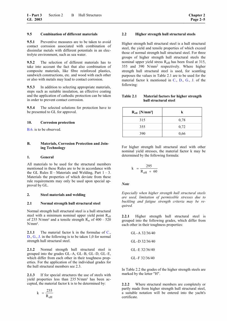
2.2 Higher strength hull structural steels
Higher strength hull structural steel is a hull structural steel, the yield and tensile properties of which exceed those of normal strength hull structural steel. For three groups of higher strength hull structural steels the nominal upper yield stress ReH has been fixed at 315, 355 and 390 N/mm2 respectively. Where higher strength hull structural steel is used, for scantling purposes the values in Table 2.1 are to be used for the material factor k mentioned in C., D., G., J. of the following:
Table 2.1 Material factors for higher strength hull structural steel
ReH [N/mm²] k
315 0,78
355 0,72
390 0,66
For higher strength hull structural steel with other nominal yield stresses, the material factor k may be determined by the following formula:
eH
295kR 60
=+
Note
Especially when higher strength hull structural steels are used, limitation of permissible stresses due to buckling and fatigue strength criteria may be re-quired.
2.2.1 Higher strength hull structural steel is grouped into the following grades, which differ from each other in their toughness properties:
GL–A 32/36/40
GL–D 32/36/40
GL–E 32/36/40
GL–F 32/36/40
In Table 2.2 the grades of the higher strength steels are marked by the letter "H".
2.2.2 Where structural members are completely or partly made from higher strength hull structural steel, a suitable notation will be entered into the yacht's certificate.
I - Part 3 GL 2003
Section 2 Hull Structures Chapter 2Page 2–5
B
2.2.3 In the drawings submitted for approval it is to be shown which structural members are made of higher strength hull structural steel. These drawings are to be placed on board in case any repairs are to be carried out.
2.3 Material selection for the hull
2.3.1 Material classes
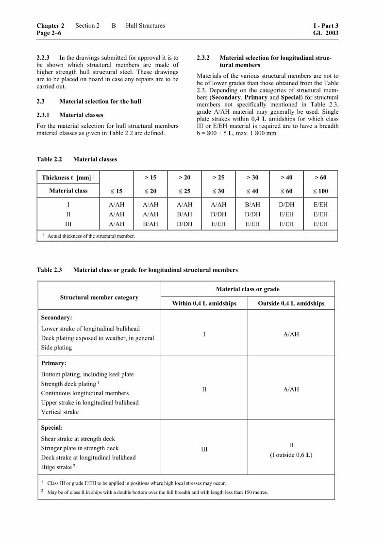
For the material selection for hull structural members material classes as given in Table 2.2 are defined.
2.3.2 Material selection for longitudinal struc-tural members
Materials of the various structural members are not to be of lower grades than those obtained from the Table 2.3. Depending on the categories of structural mem-bers (Secondary, Primary and Special) for structural members not specifically mentioned in Table 2.3, grade A/AH material may generally be used. Single plate strakes within 0,4 L amidships for which class III or E/EH material is required are to have a breadth b = 800 + 5 L, max. 1 800 mm.
Table 2.2 Material classes
Thickness t [mm] 1 > 15 > 20 > 25 > 30 > 40 > 60
Material class ≤ 15 ≤ 20 ≤ 25 ≤ 30 ≤ 40 ≤ 60 ≤ 100
I II III
A/AH A/AH A/AH
A/AH A/AH B/AH
A/AH B/AH D/DH
A/AH D/DH E/EH
B/AH D/DH E/EH
D/DH E/EH E/EH
E/EH E/EH E/EH
1 Actual thickness of the structural member.
Table 2.3 Material class or grade for longitudinal structural members
Material class or grade Structural member category
Within 0,4 L amidships Outside 0,4 L amidships
Secondary:
Lower strake of longitudinal bulkhead Deck plating exposed to weather, in general Side plating
I A/AH
Primary:
Bottom plating, including keel plate Strength deck plating 1
Continuous longitudinal members Upper strake in longitudinal bulkhead Vertical strake
II A/AH
Special:
Shear strake at strength deck Stringer plate in strength deck Deck strake at longitudinal bulkhead Bilge strake 2
III II (I outside 0,6 L)
1 Class III or grade E/EH to be applied in positions where high local stresses may occur. 2 May be of class II in ships with a double bottom over the full breadth and with length less than 150 metres.
Chapter 2 Page 2–6
Section 2 Hull Structures I - Part 3GL 2003
B
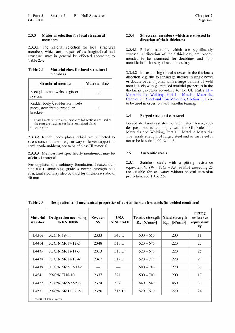
2.3.3 Material selection for local structural members
2.3.3.1 The material selection for local structural members, which are not part of the longitudinal hull structure, may in general be effected according to Table 2.4.
Table 2.4 Material class for local structural members
Structural member Material class
Face plates and webs of girder systems II 1
Rudder body 2, rudder horn, sole piece, stern frame, propeller brackets
II
1 Class I material sufficient, where rolled sections are used or the parts are machine cut from normalized plates
2 see 2.3.3.2
2.3.3.2 Rudder body plates, which are subjected to stress concentrations (e.g. in way of lower support of semi-spade rudders), are to be of class III material.
2.3.3.3 Members not specifically mentioned, may be of class I material.
For topplates of machinery foundations located out-side 0,6 L amidships, grade A normal strength hull structural steel may also be used for thicknesses above 40 mm.
2.3.4 Structural members which are stressed in direction of their thickness
2.3.4.1 Rolled materials, which are significantly stressed in direction of their thickness, are recom-mended to be examined for doublings and non-metallic inclusions by ultrasonic testing.
2.3.4.2 In case of high local stresses in the thickness direction, e.g. due to shrinkage stresses in single bevel or double bevel T-joints with a large volume of weld metal, steels with guaranteed material properties in the thickness direction according to the GL Rules II –Materials and Welding, Part 1 – Metallic Materials, Chapter 2 – Steel and Iron Materials, Section 1, I. are to be used in order to avoid lamellar tearing.
2.4 Forged steel and cast steel
Forged steel and cast steel for stem, stern frame, rud-der post, etc. is to comply with the GL Rules II –Materials and Welding, Part 1 – Metallic Materials. The tensile strength of forged steel and of cast steel is not to be less than 400 N/mm².
2.5 Austenitic steels
2.5.1 Stainless steels with a pitting resistance equivalent W (W = % Cr + 3,3 ⋅ % Mo) exceeding 25 are suitable for sea water without special corrosion protection, see Table 2.5.
Table 2.5 Designation and mechanical properties of austenitic stainless steels (in welded condition)
Material number
Designation according to EN 10088
SwedenSS
USA AISI / SAE
Tensile strength Rm [N/mm2]
Yield strength Rp0,2 [N/mm2]
Pitting resistanceequivalent
W
1.4306 X2CrNi19-11 2333 340 L 500 – 650 200 18
1.4404 X2CrNiMo17-12-2 2348 316 L 520 – 670 220 23
1.4435 X2CrNiMo18-14-3 2353 316 L 1 520 – 670 220 25
1.4438 X2CrNiMo18-16-4 2367 317 L 520 – 720 220 27
1.4439 X3CrNiMoN17-13-5 –– –– 580 – 780 270 33
1.4541 X6CrNiTi18-10 2337 321 500 – 700 200 17
1.4462 X2CrNiMoN22-5-3 2324 329 640 – 840 460 31
1.4571 X6CrNiMoTi17-12-2 2350 316 Ti 520 – 670 220 24 1 valid for Mo > 2,5 %
I - Part 3 GL 2003
Section 2 Hull Structures Chapter 2Page 2–7
B
2.5.2 Where austenitic steels are applied having a ratio
p0,2
m
R0,5
R≤
on special approval the 1 % proof stress Rp1,0 may be used for scantling purposes instead of the 0,2 % proof stress Rp0,2.
2.6 Welding
The following information summarizes some principle aspects to be considered for the design of Yachts. Detailed requirements are contained in the GL Rules II – Materials and Welding, Part 3 – Welding.
2.6.1 Information contained in manufacturing documents
2.6.1.1 The shapes and dimensions of welds and, where proof by calculation is supplied, the require-ments applicable to welded joints (the weld quality grade, detail category) are to be stated in drawings and other manufacturing documents (parts lists, welding and inspection schedules). In special cases, e.g. where special materials are concerned, the documents shall also state the welding method, the welding consum-ables used, heat input and control, the weld build-up and any post-weld treatment which may be required.
2.6.1.2 Symbols and signs used to identify welded joints shall be explained if they depart from the sym-bols and definitions contained in the relevant stan-dards (e.g. DIN standards). Where the weld prepara-tion (together with approved methods of welding) conforms both to normal shipbuilding practice and to these Rules and recognized standards, where applica-ble, no special description is needed.
2.6.2 Materials, weldability
2.6.2.1 Only base materials of proven weldability may be used for welded structures. Any approval conditions of the steel or of the procedure qualifica-tion tests and the steelmaker's recommendations are to be observed.
2.6.2.2 For normal strength hull structural steels grades A, B, D and E which have been tested by GL, weldability is considered to have been proven. No measures beyond those laid down in these welding rules need therefore to be taken.
2.6.2.3 Higher strength hull structural steels grade AH/DH/EH/FH which have been approved by GL in accordance with the relevant requirements of Rules for Materials and Welding, have had their weldability examined and, provided their handling is in accor-dance with normal shipbuilding practice, may be con-sidered to be proven.
2.6.2.4 High strength (quenched and tempered) fine grain structural steels, low temperature steels, stainless
and other (alloyed) structural steels require special approval by GL. Proof of weldability of the respective steel is to be presented in connection with the welding procedure and welding consumables.
2.6.2.5 Cast steel and forged parts require testing by GL. The carbon content of components for welded structures must not exceed 0,23 % C (piece analysis not exceeding 0,25 % C).
2.6.2.6 Welding consumables used are to be suitable for the parent metal to be welded and are to be ap-proved by GL. Where filler materials having tensile properties deviating (downwards) from the parent metal are used (upon special agreement by GL) this fact must be taken into account when dimensioning the weld joints.
2.6.3 Manufacture and testing
2.6.3.1 The manufacture of welded structural com-ponents may only be carried out in workshops or plants that have been approved by GL. The require-ments that have to be observed in connection with the fabrication of welded joints are laid down in II – Materials and Welding, Part 3 – Welding.
2.6.3.2 The weld quality grade of welded joints without proof by calculation (see 2.6.1.1) depends on the significance of the welded joint for the total struc-ture and on its location in the structural element (loca-tion relative to the main stress direction) and on its stressing. For details concerning the type, scope and manner of testing, see Rules II – Materials and Weld-ing, Part 3 – Welding, Chapter 3 – Welding in the Various Fields of Application, Section 1, I.
2.6.4 General design principles
2.6.4.1 During the design stage welded joints are to be planned such as to be accessible during fabrication, to be located in the best possible position for welding and to permit the proper welding sequence to be fol-lowed.
2.6.4.2 Both the welded joints and the sequence of welding involved are to be so planned as to enable residual welding stresses to be kept to a minimum in order that no excessive deformation occurs. Welded joints should not be over dimensioned.
2.6.4.3 When planning welded joints, it must first be established that the type and grade of weld envisaged, such as full root weld penetration in the case of HV or DHV (K) weld seams, can in fact be perfectly exe-cuted under the conditions set by the limitations of the manufacturing process involved. If this is not the case, a simpler type of weld seam shall be selected and its possibly lower load bearing capacity taken into ac-count when dimensioning the component.
Chapter 2 Page 2–8
Section 2 Hull Structures I - Part 3GL 2003
B
2.6.4.4 Highly stressed welded joints, which there-fore, are generally subject to examination, are to be so designed that the most suitable method of testing for faults can be used (radiography, ultrasonic, surface crack testing methods) in order that a reliable exami-nation may be carried out.
2.6.4.5 Special characteristics peculiar to the mate-rial, such as the lower strength values of rolled mate-rial in the thickness direction or the softening of cold worked aluminium alloys as a result of welding, are factors which have to be taken into account when designing welded joints.
2.6.4.6 In cases where different types of material are paired and operate in sea water or any other electro-lytic medium, for example welded joints made be-tween unalloyed carbon steels and stainless steels in the wear-resistant cladding in rudder nozzles or in the cladding of rudder shafts, the resulting differences in potential greatly increase the susceptibility to corro-sion and must therefore be given special attention. Where possible, such welds are to be positioned in locations less subject to the risk of corrosion (such as the outside of tanks) or special counter-measures are to be taken (such as the provision of a protective coat-ing or cathodic protection).
2.6.5 Design details
For design details see the GL Rules Part 1 – Seagoing Ships, Chapter 1 – Hull Structures, Section 19.
3. Aluminium alloys and welding
The following information is based on the GL Rules II – Materials and Welding, Part 1 – Metallic Materials, Chapter 3 – Non-Ferrous Metals, Section 1 with the aim of summarizing aspects applicable for the design of Yachts.
3.1 General
3.1.1 The following requirements are applicable to products made from wrought aluminium alloys having a product thickness of 3 to 50 mm inclusive. Require-ments applicable to products having thicknesses out-side this range are to be specially agreed with GL.
3.1.2 Alloys and material conditions which differ from the specified requirements given below, but which conform to national standards or the manufac-turer’s material specifications may be used provided that their properties and suitability for use, and also
their weldability have been checked by GL and that GL has approved their use.
3.1.3 Alloy designations and material conditions specified herein comply with the designations of the Aluminium Association. With regard to the definition of the material conditions European standard EN 515 is applicable.
3.2 Requirements to be met by manufacturers
Manufacturers wishing to supply products in accor-dance with these requirements must be approved by GL for the alloys and product forms in question.
3.3 General characteristics of products
3.3.1 The products must have a smooth surface compatible with the method of manufacture and must be free of defects liable to impair further manufactur-ing processes or the proposed application of the prod-ucts, e.g. cracks, laps, appreciable inclusions of extra-neous substances and major mechanical damage.
3.3.2 Surface defects may be repaired only by grinding provided that this is accomplished with a gentle transition to the adjacent surface of the product and that the dimensions remain within the tolerance limits. Repair by welding is not permitted. For repair purposes only tools are to be used which are exclu-sively applied for aluminium processing.
3.4 Aluminium alloys without post treatment for hardening
3.4.1 Aluminium alloys of 5000 series in 0 condi-tion (annealed) or in H111 condition (annealed flat-tened) retain their original mechanical characteristics and therefore are not subject to a drop in mechanical strength in the welded areas.
3.4.2 These types of aluminium alloys are used for plates, strips and rolled sections and a representative list is defined in Table 2.6. This list, as well as the list of Table 2.7, is not exhaustive. Other aluminium al-loys may be considered provided the specification (manufacture, chemical composition, temper, me-chanical properties, welding, etc.) and the scope of application is submitted to GL and approved.
3.4.3 Unless otherwise specified, the Young's mo-dulus of aluminium alloys is equal to 70 000 N/mm2 and the Poisson's ratio equal to 0,33.
I - Part 3 GL 2003
Section 2 Hull Structures Chapter 2Page 2–9
B
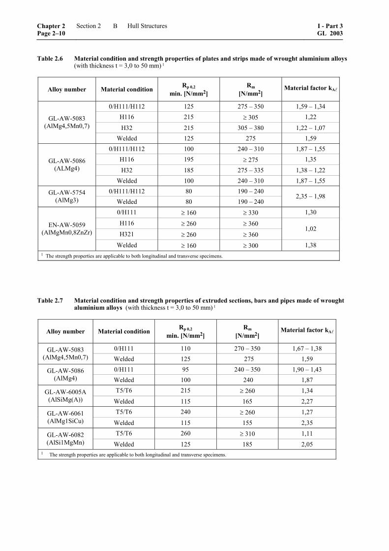
Table 2.6 Material condition and strength properties of plates and strips made of wrought aluminium alloys (with thickness t = 3,0 to 50 mm) 1
Alloy number Material condition Rp 0,2 min. [N/mm2]
Rm [N/mm2]
Material factor kA
0/H111/H112 125 275 – 350 1,59 – 1,34 H116 215 ≥ 305 1,22
H32 215 305 – 380 1,22 – 1,07 GL-AW-5083
(AlMg4,5Mn0,7)
Welded 125 275 1,59 0/H111/H112 100 240 – 310 1,87 – 1,55
H116 195 ≥ 275 1,35
H32 185 275 – 335 1,38 – 1,22 GL-AW-5086
(ALMg4)
Welded 100 240 – 310 1,87 – 1,55 0/H111/H112 80 190 – 240 GL-AW-5754
(AlMg3) Welded 80 190 – 240 2,35 – 1,98
0/H111 ≥ 160 ≥ 330 1,30
H116 ≥ 260 ≥ 360 H321 ≥ 260 ≥ 360
1,02 EN-AW-5059 (AlMgMn0,8ZnZr)
Welded ≥ 160 ≥ 300 1,38 1 The strength properties are applicable to both longitudinal and transverse specimens.
Table 2.7 Material condition and strength properties of extruded sections, bars and pipes made of wrought aluminium alloys (with thickness t = 3,0 to 50 mm) 1
Alloy number Material condition Rp 0,2 min. [N/mm2]
Rm [N/mm2]
Material factor kA
0/H111 110 270 – 350 1,67 – 1,38 GL-AW-5083 (AlMg4,5Mn0,7) Welded 125 275 1,59
0/H111 95 240 – 350 1,90 – 1,43 GL-AW-5086 (AlMg4) Welded 100 240 1,87
T5/T6 215 ≥ 260 1,34 GL-AW-6005A (AlSiMg(A)) Welded 115 165 2,27
T5/T6 240 ≥ 260 1,27 GL-AW-6061 (AlMg1SiCu) Welded 115 155 2,35
T5/T6 260 ≥ 310 1,11 GL-AW-6082 (AlSi1MgMn) Welded 125 185 2,05
1 The strength properties are applicable to both longitudinal and transverse specimens.
Chapter 2 Page 2–10
Section 2 Hull Structures I - Part 3GL 2003
B

3.5 Hardened aluminium alloys
3.5.1 Aluminium alloys can be hardened by work hardening (Series 5000 other than condition 0 or H111) or by heat treatment (series 6000).
3.5.2 These types of aluminium alloys are used for extruded section, bars and pipes and a representative selection is defined in Table 2.7.
3.6 Material selection
3.6.1 The choice of aluminium alloys according to Table 2.7 is mainly recommendable for extrusions and where no excessive welding will be necessary. Other-wise only the mechanical characteristics of 0 or H111 conditions can be taken into account. Higher mechani-cal characteristics to be used must be duly justified.
3.6.2 In case of structures subjected to low service temperatures or intended for other particular applica-tions, the alloys to be employed are to be defined in each separate case by GL, which will state the accept-ability requirements and conditions.
3.6.3 For forgings and castings to be applied, re-quirements for chemical composition and mechanical properties are to be defined in each separate case by GL.
3.7 Welding
3.7.1 General requirements
For welding of aluminium the requirements of rele-vant GL Rules apply. In particular, existing welding procedure qualifications may be approved by GL or GL will decide if new qualifications will become necessary. Welding shops and the employed welders have to be approved for the relevant welding proce-dures.
3.7.2 Influence of welding on mechanical char-acteristics
3.7.2.1 Aluminium alloys of series 5000 in 0 condi-tion (annealed) or in H111 condition (annealed flat-tened) are not subject to a drop in mechanical strength in the welded areas. But welding heat input lowers the mechanical strength of alloys of series 5000 with other conditions and of that of series 6000, which are hard-ened by heat treatment.
3.7.2.2 For heat-affected welding zones the me-chanical characteristics of series 5000 to be considered are, normally, those of condition 0 or H111. Higher mechanical characteristics may be taken into account, provided they are duly justified.
3.7.2.3 For heat-affected zones the mechanical char-acteristics of series 6000 to be considered are, nor-mally, to be indicated by the supplier.
3.7.2.4 The heat-affected zone may be taken to ex-tend 25 mm on each side of the weld axis.
3.7.3 Preparation for welding
Edge cutting, to be carried out in general by machin-ing, is to be regular and without burrs or cuts.
The structural parts to be welded as well as those adjacent, even if they have been previously pickled, are to be cleaned carefully before welding, using suit-able mechanical means, such as stainless steel wire brushes, so as to eliminate oxides, grease or other foreign matter which could give rise to welding de-fects.
3.7.4 Welding processes
3.7.4.1 In general, the welding of the hull structures is to be performed with the MIG (metal-arc inert gas) or the TIG (tungsten-arc inert gas) processes using welding consumables recognized as suitable for the base material to be used. For joints with extreme stress and execution requirements (gas and liquid tight, etc.) the TIG method is recommendable, otherwise the MIG method may be used. Welding processes and filler materials other than those mentioned are to be individually considered by GL at the time of the ap-proval of welding procedures.
3.7.4.2 For the authorization to use welding proce-dures in production, the following details are to be stated:
– grade and temper of parent and filler materials
– weld execution procedures: type of joint (e.g. butt-joint, fillet joint); edge preparation (e.g. thicknesses, bevelling, right angle edges); weld-ing position (e.g. flat, vertical, horizontal) and other parameters (e.g. voltage, amperage, gas flow capacity)
– welding conditions (e.g. cleaning procedures of edges to be welded, protection from environ-mental atmosphere)
– special operating requirements for butt-joints, for example for plating: welding to be started and completed on end pieces outside the joint, back chipping, arrangements for repairs conse-quent to possible arc restarts
– type and extent of controls during production
3.7.4.3 Establishing high welding speeds to reduce the transfer of thermal loads is recommended.
3.7.4.4 Impermissible reinforcements of seams and hardened transition areas in the basic material shall be carefully removed.
3.7.5 Inspections
3.7.5.1 Inspections of welded connections by GL Surveyors are, in general, those specified below, with the extent of inspection to be defined by GL on a case by case basis:
I - Part 3 GL 2003
Section 2 Hull Structures Chapter 2Page 2–11
B
– inspection of base materials for compliance with the requirements 3.4 to 3.6 and for compliance of structures with the approved plans
– inspection of the use and application conditions of welding procedures for compliance with those approved and verification that qualified welders are employed
– visual examination of edge preparations, root chipping and execution of welds in way of struc-tural connections
– examination of radiographs of welded joints (radiographing is to be performed, if necessary, depending on the extent of the examinations), and inspection of performance of execution of the ultrasonic or magnetic particle examinations, which may be required
– inspection of any repairs, to be performed with procedures and inspection methods at the discre-tion of the GL Surveyor
3.7.5.2 The limits for imperfections in welded joints of aluminium alloys are defined in the GL Rules II - Materials and Welding, Part 3 – Welding, Chapter 3 – Welding in the Various Fields of Application.
3.7.5.3 Irrespective of the extent of such inspections, it is the responsibility of the builder to ensure that the manufacturing procedures, processes and sequences are in compliance with relevant GL requirements, approved plans and sound working practice. For this purpose, the shipyard is to have its own quality man-agement system.
3.7.6 General design principles
The following design principles shall be applied:
– transfer of welding seams to low stress areas, like the neutral axis of a girder by using ex-truded sections for the upper and lower flange
– location of welding seams in such a way, that the thermal load from welding will be led to a far extent to extrusion profiles with big wall thicknesses
– edge preparation, alignment of joints are to be appropriate to the type of joint and welding po-sition, and comply with GL Rule requirements for the welding procedures adopted
– for correct execution of welded joints, sufficient accessibility is necessary, depending on the welding process adopted and the welding posi-tion
– unfavourable welding positions have to be avoided
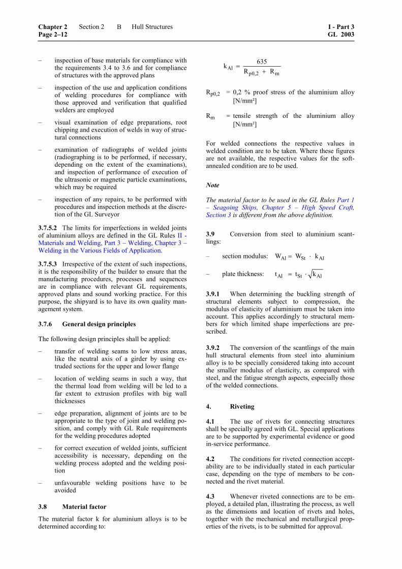
3.8 Material factor
The material factor k for aluminium alloys is to be determined according to:
Alp0,2 m
635kR R
=+
Rp0,2 = 0,2 % proof stress of the aluminium alloy [N/mm²]
Rm = tensile strength of the aluminium alloy [N/mm²]
For welded connections the respective values in welded condition are to be taken. Where these figures are not available, the respective values for the soft-annealed condition are to be used.
Note
The material factor to be used in the GL Rules Part 1 – Seagoing Ships, Chapter 5 – High Speed Craft, Section 3 is different from the above definition.
3.9 Conversion from steel to aluminium scant-lings:
– section modulus: Al St AlW W k= ⋅
– plate thickness: Al St Alt t k= ⋅
3.9.1 When determining the buckling strength of structural elements subject to compression, the modulus of elasticity of aluminium must be taken into account. This applies accordingly to structural mem-bers for which limited shape imperfections are pre-scribed.
3.9.2 The conversion of the scantlings of the main hull structural elements from steel into aluminium alloy is to be specially considered taking into account the smaller modulus of elasticity, as compared with steel, and the fatigue strength aspects, especially those of the welded connections.
4. Riveting
4.1 The use of rivets for connecting structures shall be specially agreed with GL. Special applications are to be supported by experimental evidence or good in-service performance.
4.2 The conditions for riveted connection accept-ability are to be individually stated in each particular case, depending on the type of members to be con-nected and the rivet material.
4.3 Whenever riveted connections are to be em-ployed, a detailed plan, illustrating the process, as well as the dimensions and location of rivets and holes, together with the mechanical and metallurgical prop-erties of the rivets, is to be submitted for approval.
Chapter 2 Page 2–12
Section 2 Hull Structures I - Part 3GL 2003
B

4.4 GL may, at its discretion, require tension, compression and shear tests to be carried out on specimens of riveted connections constructed under the same conditions as during actual hull construction, to be witnessed by a GL Surveyor.
4.5 GL reserve the right to accept the results of tests performed by recognized bodies or other Classi-fication Societies.
5. Welding transition joints
5.1 General
5.1.1 For welded transitions of the hull structures between steel and aluminium alloys explosion-bonded steel-aluminium transition joints may be used. This use for plates or profiles is subject to GL's agreement.
5.1.2 Any such jointing system is to be type-approved by GL.
5.1.3 Qualifications tests for welding procedures are to be carried out for each joint configuration.
5.1.4 A welding booklet giving preparations and various welding parameters for each type of assembly is to be submitted for review.
5.2 Types of explosion-bonded joints
According to the present state of technology and ap-plication, the following types of explosion-bonded joints are used: – butt welds in the welding transition as such – joints of platings (walls, decks), as a cruciform
joint with coaming or a T-joint without coaming – joints of stiffeners, as a cruciform joint with
coaming or a T-joint without coaming – joints of transverse walls, as cruciform joint
with coaming or T-joint without coaming
5.3 Permissible transition stresses
For some widely used steel-aluminium transition joints the permissible stresses to be transmitted are defined in Table 2.8. Owing to the fact, that in general the connection between steel and aluminium is of lower specific strength, a larger surface is therefore required for force transmission.
5.4 Inadmissible heating
For all connections it has to be ensured, that the bond zone between steel and aluminium is not inadmissibly heated above a maximum temperature of 300 °C, as this would cause embrittlement implying the risk of failures.
6. Corrosion protection
6.1 General
For corrosion protection the requirements according to VI – Additional Rules and Guidelines, Part 9 – Ma-terials and Welding, Chapter 6 – Guidelines for Corro-sion Protection and Coating Systems have to be met. In addition the requirements below shall be observed. Special solutions concerning material selection, coat-ings, cathodic protection systems or other methods may be accepted after examination.
6.2 Shop primers
Shop primers are used to provide protection of the steel parts during storage, transport and work proc-esses. Customarily, coatings with a thickness of 15 to 20 μm are applied. This should provide corrosion protection for a period of approx. 6 months.
6.3 Hollow spaces
Hollow spaces, such as those in closed box girders, tube supports and the like, which either can be shown to be air tight or are accepted as such from normal shipbuilding experience, need not have their internal surfaces protected. During assembling, however such hollow spaces must be kept clean and dry.
6.4 Combination of materials
Preventive measures are to be taken to avoid contact corrosion associated with the combination of dissimi-lar metals with different potentials in an electrolyte solution, such as seawater. In addition to selecting appropriate materials, steps such as suitable insulation, an effective coating and the application of cathodic protection can be taken in order to prevent contact corrosion.
Table 2.8 Material combination and permissible stresses
Material combination
Type of bonding Steel Aluminium alloy
Permissible tensile stress through
thickness [N/mm2]
Permissible shear stress
[N/mm2]
Explosion-bonded All types All types 60 60
I - Part 3 GL 2003
Section 2 Hull Structures Chapter 2Page 2–13
B
6.4.1 Heterogeneous assemblies of steel and aluminium alloys
Connections between aluminium alloy and steel parts, if any, are to be protected against corrosion by means of coatings applied by suitable procedures agreed by GL.
In any case, any direct contact between steel and alu-minium alloy is to be avoided (e.g. by means of zinc or cadmium plating of the steel parts and application of a suitable coating on the corresponding light alloy parts).
6.5 Corrosion protection of ballast water tanks
All seawater ballast tanks having boundaries formed by the vessel’s side shell (bottom, outside plating, deck) must be provided with a corrosion protection system consisting of coating and cathodic protection
6.6 Corrosion protection of the underwater hull
6.6.1 Coatings based on epoxy, polyurethane and polyvinyl chloride are considered suitable.
6.6.2 The coating manufacturer’s instructions with regard to surface preparation as well as application conditions and processing must be observed.
6.6.3 The coating system without antifouling shall:
– have a minimum dry film thickness of 250 μm
– provide cathodic protection in accordance with recognized standards
– be suitable for being cleaned underwater by mechanical means
6.6.4 The cathodic protection can be provided by means of sacrificial anodes, or by impressed current systems. Under normal conditions for steel, a protec-tion current density of at least 10 mA/m² must be ensured. Hulls or components made of aluminium and aluminium alloys, which are permanently immersed in seawater need to be protected by sacrificial anodes. For hull structures or components of zinc-free alumin-ium materials which are permanently submerged in seawater, cathodic protection with a protective poten-tial of less than – 0,55 V by sacrificial anodes is re-quired. A cathodic protection is especially needed, if galvanic corrosion is to be expected due to a bimetal-lic couple between the submerged aluminium alloy structure and other parts, e.g. propulsion components such as stainless steel propeller shafts, bronze propel-lers or steel hydrojets.
Therefore metallic connection between aluminium alloy structures and other metals should be avoided.
6.6.5 In the case of impressed current systems, overprotection due to inadequately low potential is to be avoided. A screen (dielectric shield) is to be pro-vided in the immediate vicinity of the impressed-current anodes.
6.7 Corrosion protection of austenitic stainless steels
Stainless steels and stainless steel castings exhibit a passive surface state in seawater. Accordingly, coating these types of steel is only recommended under spe-cial conditions. In general uncoated stainless steels are not protected by cathodic corrosion protection if they are suitable for withstanding the corrosion stress. Coated stainless steels must be cathodically protected in the submerged zone.
7. Fibre reinforced plastics, sandwich con-structions and bonding
Refer to GL Rules II – Materials and Welding, Part 2 – Non-metallic Materials, Chapter 1 – Fibre Rein-forced Plastics and Adhesive Joints.
7.1 Approval of materials
All materials to be used during production of compo-nents from FRP shall first be assessed and approved by GL. Approval by other organizations can be recog-nized following agreement by GL, provided the re-spective approval procedure is in accordance with GL requirements.
7.2 Properties of the materials
The basic properties of the different materials shall be verified by test certificate of a recognized testing body. These values shall fulfil the minimum require-ments specified in the relevant GL Rules.
7.3 Processing and surveillance
7.3.1 All manufacturing facilities, store rooms and their operational equipment shall fulfil the require-ments of the responsible safety authorities and profes-sional employers liability insurance associations. The manufacturer is exclusively responsible for compli-ance with this requirements.
7.3.2 GL reserve the right to carry out inspections without giving prior notice. The manufacturer shall grant GL Surveyors access to all areas and shall pre-sent all documentation concerning records and tests carried out.
8. Cold-moulded wood and glueing
8.1 General
A cold-moulded wood laminate consists of at least three layers of veneer/lamellae.
Chapter 2 Page 2–14
Section 2 Hull Structures I - Part 3GL 2003
B

8.2 Wood
8.2.1 Any of the timbers suitable for boat building may be used.
8.2.2 Timber envisaged for use in this type of con-struction is to be cut in such a way that the inclination of the annual rings is no less than 30°, i.e. the angle between the chord of the flattest annual ring, and the face of a lamella or strip of veneer must not be less than 30°. The fibres shall be oriented parallel to the edge of a lamella, if possible. Veneers for making plating may be sliced or sawn.
8.3 Glues and adhesives
Only adhesives and glues tested and approved by GL may be used. Adhesives and glues shall have passed the tests in accordance with Section 2 of DIN 68141 - "Prüfung von Leimen und Leimverbindungen für tragende Holzbauteile" (Testing of glues and adhesive combinations for load bearing wooden components). Relevant confirmation and/or test certificates are to be submitted to GL.
In accordance with current practice, mixed adhesives will hereinafter also be referred to as glues.
8.4 Works prerequisites and quality assurance
Companies producing wooden hulls and components cold-moulded by glueing shall be qualified for the work to be carried out as regards their workshop equipment, internal quality control, manufacturing process as well as the training and qualification of the personnel carrying out and supervising the work.
Providing the prerequisites for approval have been met, suitability will be certified for the works on ap-plication by a GL shop approval.
9. Wood and joining of wood materials
The following requirements are an excerpt of the GL Rules II – Materials and Welding, Part 2 – Non-metallic Materials, Chapter 2 – Wood with the aim of summarizing all aspects directly necessary for the design of Yachts.
9.1 General
9.1.1 Timber selection according to the field of application
Only proven boatbuilding wood shall be used for all timber components exposed to water and weather, i.e. timber with good resistance to water and weather, fungal attack and insect infestation, as well as with good mechanical properties that are also suitable for the particular application. Furthermore, it shall have
low swelling and shrinkage properties. For compo-nents not exposed to water or weather, and not requir-ing strength, timber of lower durability may be used.
9.1.2 Quality
The timber used in boatbuilding shall be long-grained and of best quality, i.e. free from sap, shakes, objec-tionable knots and other defects. Twisted-grown or rough saw cut shall not be used.
9.1.3 Drying
The timber used shall be well seasoned and suffi-ciently dried in a suitable drying kiln. In case of forced drying, the residual moisture content shall not be more than 10 %. When processing, this content shall not exceed 15 % as a result of hygroscopic behaviour.
9.2 Solid wood
9.2.1 Radially sawn timber shall mainly be used for boatbuilding. The angle of the annual rings to the lower sawn edge shall not be less than 45°.
9.2.2 Table 2.9 shows the number of different types of timber and their most important properties, as well as tensile, compressive and bending strength. Since these properties can vary in the case of timber of the same type, or even within the same trunk, no abso-lute values are indicated in the table, but rather charac-teristic values. The timber listed is divided into dura-bility groups from I to V. The timber used in boat-building shall, if exposed to the weather or used for the primary structural components of a boat, belong to at least durability group III.
9.2.3 In place of the timber listed in Table 2.9, other types can be used if the durability and the tech-nological values are verified and are equivalent. The manufacturer shall always be responsible for the cor-rect selection of the quality and type of wood.
9.2.4 The safety factors used in the strength calcu-lation shall be agreed in each case with GL.
9.3 Boatbuilding plywood
9.3.1 General
9.3.1.1 All plywood components exposed to water and weather, or used in primary structural components (such as the deck, shell and bulkheads), shall be pro-duced from boatbuilding plywood that has been tested according to GL Rules.
9.3.1.2 The boatbuilding plywood consists of at least three veneers bonded crosswise together by means of curable synthetic-resin adhesives. The resistance of these adhesives to water and weather shall be demon-strated by long-term and outdoor testing.
I - Part 3 GL 2003
Section 2 Hull Structures Chapter 2Page 2–15
B

Table 2.9 Timber durability groups and characteristic values in accordance with DIN 68364
Durability group Density Mean breaking strengths
Timber type
I – V [g/cm3] Tension [N/mm2]
Compression [N/mm2]
Bending [N/mm2]
Coniferous
Pine III – IV 0,52 100 45 80
Oregon pine III 0,54 100 50 80
Larch III 0,59 105 48 93
Deciduous
Khaya mahogany III 0,50 75 43 75
True mahogany II 0,54 100 45 80
Sapele mahogany III 0,64 85 57 69
Utile II 0,59 100 58 100
Meranti, red III 0,59 129 53 105
Iroko I – II 0,63 79 55 95
Makore I – II 0,66 85 53 103
Oak II 0,67 110 52 95
Teak I 0,69 115 58 100
Yang III 0,76 140 70 125 1 Durability groups:
I = very good II = good III = average IV = moderate V = poor
Chapter 2 Page 2–16
Section 2 Hull Structures I - Part 3GL 2003
B

Table 2.10 Plywood strength and durability groups
Durability group 1 Density Mean tensile strength of plywood
Timber type Botanical name
I – V Approx. [g/cm3]
Longitudinal [N/mm2]
Transverse [N/mm2]
Bending [N/mm2]
Strength group F1 (for loadbearing components)
Teak Tectona grandis I 0,64 ≥ 40 ≥ 30
Makoré Dumoria hekelii I 0,62 ≥ 40 ≥ 30
Douka Dumoria africana I 0,62 ≥ 40 ≥ 30
Utile Entandro-phragma utile II 0,57 ≥ 40 ≥ 30
Sapele mahogany
Entandro-phragma cylindricum III 0,59 ≥ 40 ≥ 30
Oak Querus robur II 0,63 ≥ 40 ≥ 30
Strength group: F2
American mahogany
Swietenia macrophylla II 0,49 < 40 < 30
African mahogany Khaya ivorensis II – III 0,45 < 40 < 30
Okoumé (Gaboon)
Aucoumea klaineana IV – V 0,41 < 40 < 30
1 Durability groups: I = very good II = good III = average IV = moderate V = poor
I - Part 3 GL 2003
Section 2 Hull Structures Chapter 2Page 2–17
B
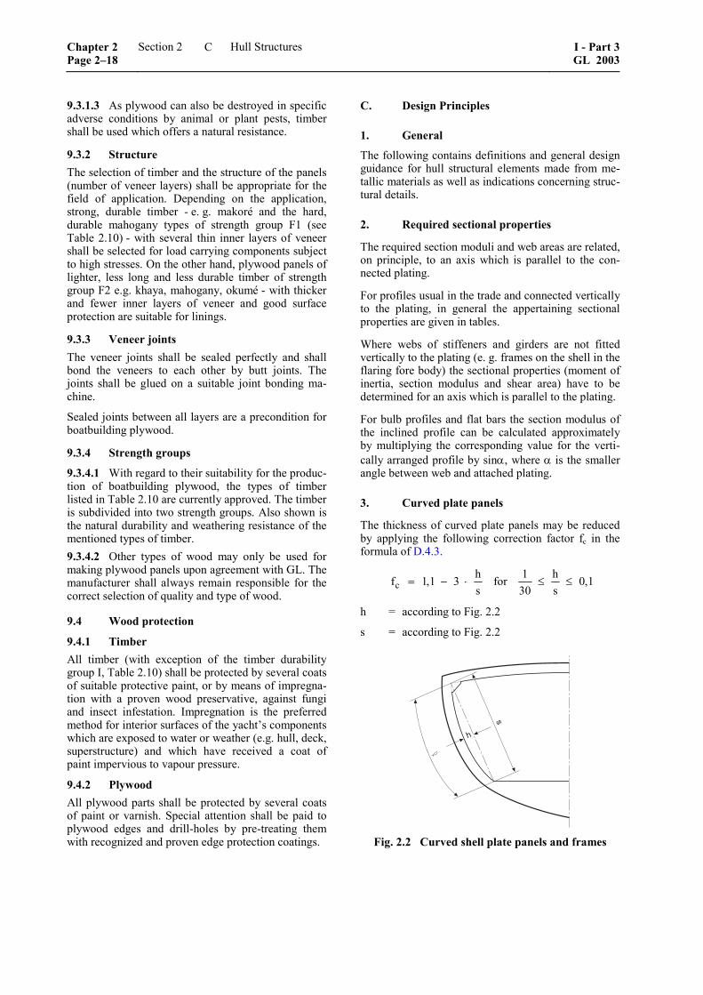
9.3.1.3 As plywood can also be destroyed in specific adverse conditions by animal or plant pests, timber shall be used which offers a natural resistance.
9.3.2 Structure The selection of timber and the structure of the panels (number of veneer layers) shall be appropriate for the field of application. Depending on the application, strong, durable timber - e. g. makoré and the hard, durable mahogany types of strength group F1 (see Table 2.10) - with several thin inner layers of veneer shall be selected for load carrying components subject to high stresses. On the other hand, plywood panels of lighter, less long and less durable timber of strength group F2 e.g. khaya, mahogany, okumé - with thicker and fewer inner layers of veneer and good surface protection are suitable for linings.
9.3.3 Veneer joints The veneer joints shall be sealed perfectly and shall bond the veneers to each other by butt joints. The joints shall be glued on a suitable joint bonding ma-chine.
Sealed joints between all layers are a precondition for boatbuilding plywood.
9.3.4 Strength groups
9.3.4.1 With regard to their suitability for the produc-tion of boatbuilding plywood, the types of timber listed in Table 2.10 are currently approved. The timber is subdivided into two strength groups. Also shown is the natural durability and weathering resistance of the mentioned types of timber. 9.3.4.2 Other types of wood may only be used for making plywood panels upon agreement with GL. The manufacturer shall always remain responsible for the correct selection of quality and type of wood.
9.4 Wood protection
9.4.1 Timber All timber (with exception of the timber durability group I, Table 2.10) shall be protected by several coats of suitable protective paint, or by means of impregna-tion with a proven wood preservative, against fungi and insect infestation. Impregnation is the preferred method for interior surfaces of the yacht’s components which are exposed to water or weather (e.g. hull, deck, superstructure) and which have received a coat of paint impervious to vapour pressure.
9.4.2 Plywood All plywood parts shall be protected by several coats of paint or varnish. Special attention shall be paid to plywood edges and drill-holes by pre-treating them with recognized and proven edge protection coatings.
C. Design Principles
1. General
The following contains definitions and general design guidance for hull structural elements made from me-tallic materials as well as indications concerning struc-tural details.
2. Required sectional properties
The required section moduli and web areas are related, on principle, to an axis which is parallel to the con-nected plating.
For profiles usual in the trade and connected vertically to the plating, in general the appertaining sectional properties are given in tables.
Where webs of stiffeners and girders are not fitted vertically to the plating (e. g. frames on the shell in the flaring fore body) the sectional properties (moment of inertia, section modulus and shear area) have to be determined for an axis which is parallel to the plating.
For bulb profiles and flat bars the section modulus of the inclined profile can be calculated approximately by multiplying the corresponding value for the verti-cally arranged profile by sinα, where α is the smaller angle between web and attached plating.
3. Curved plate panels
The thickness of curved plate panels may be reduced by applying the following correction factor fc in the formula of D.4.3.
chf 1,1 3s
= − ⋅ for 1 h 0,130 s
≤ ≤
h = according to Fig. 2.2
s = according to Fig. 2.2
�
�
Fig. 2.2 Curved shell plate panels and frames
Chapter 2 Page 2–18
Section 2 Hull Structures I - Part 3GL 2003
C
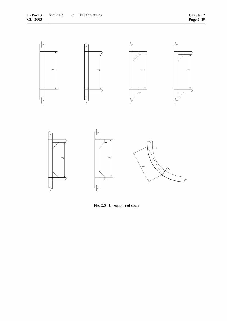
Fig. 2.3 Unsupported span
I - Part 3 GL 2003
Section 2 Hull Structures Chapter 2Page 2–19
C

4. Curved frames and girders
For curved frames and girders, the section modulus may be reduced by applying the factor fcs in the for-mula of D.4.4.2.
csh hf 1,15 5 for 0,03 0,1s s
= − ⋅ ≤ ≤
h = according to Fig. 2.2 s = according to Fig. 2.2
5. Unsupported span
5.1 Stiffeners, frames
The unsupported span is the length of the stiffeners between two supporting girders or else their length including end attachments (brackets), see Fig. 2.3.
5.2 Transverses and girders
The unsupported span of transverses and girders is to be determined according to Fig. 2.4, depending on the type of end attachment.
In special cases, the rigidity of the adjoining girders is to be taken into account when determining the span of girder.
�
�
�
� ��
� �
�
�
�
�
�� �
��
�
Fig. 2.4 Unsupported span depending on end attachment
6. End attachments
6.1 Definitions
For determining scantlings of beams, stiffeners and girders the terms "constraint" and "simple support" will be used.
"Constraint" will be assumed where for instance the stiffeners are rigidly connected to other members by means of brackets or are running throughout over supporting girders.
"Simple support" will be assumed where for instance the stiffener ends are sniped or the stiffeners are con-nected to plating only, see also 6.4.
6.2 Design of details
Structural details are to be so designed and con-structed as to minimize hard spots, notches and other structural discontinuities leading to stress concentra-
tions. Therefore sharp corners and abrupt changes in sections are to be avoided. Toes of brackets and ends of members are not to terminate on plating without attachment to an adjacent member, unless specially approved.
6.3 Brackets
6.3.1 For the scantlings of brackets the required section modulus of the section is decisive. Where sections of different section moduli are connected to each other, the scantlings of the brackets are generally governed by the smaller section.
6.3.2 The thickness of the brackets is not to be less than:
[ ]3 K1
Wt c t mmk
= ⋅ +
c = 1,20 for non-flanged brackets
= 0,95 for flanged brackets
k1 = material factor k for the section, according to B.2.2
W = section modulus of smaller section [cm3]
tmin = 5,5 mm
tmax = web thickness of smaller section
tK = corrosion allowance according to D.4.1.2
6.3.3 The arm length of brackets is not to be less than:
3 2 t1
W46,2 k ck
= ⋅ ⋅ ⋅
min 100 mm=
W = see 6.3.2
k1 = see 6.3.2
k2 = material factor k for the bracket, according to B.2.2
ct = a
tt
ta = "as built" thickness of bracket [mm] ≥ t ac-cording to 6.3.2
The arm length is the length of the welded connec-tion.
Note
For deviating arm lengths the thickness of brackets is to be estimated by direct calculations considering sufficient safety against buckling.
Chapter 2 Page 2–20
Section 2 Hull Structures I - Part 3GL 2003
C

6.3.4 Where flanged brackets are used, the width of flange is to be determined according to the following formula:
[ ]Wb 40 mm30
= +
b = not to be taken less than 50, not greater than 90 mm
W = see 6.3.2
6.4 Sniped ends of stiffeners
Stiffeners may be sniped at the ends, if the thickness of the plating supported by stiffeners is not less than:
[ ]eH
p a ( 0,5 a)t = c mmR
⋅ − ⋅
p = design load in [kN/m2], see GL-Rules Part 1 – Seagoing Ships, Chapter 1 – Hull Struc-tures, Section 4
= unsupported length of stiffener [m]
a = spacing of stiffener in [m]
ReH = minimum nominal upper yield point of the plating's material [N/mm²] according to B.2.2
c = 15,8 for watertight bulkheads and for tank bulkheads when loaded by p2 accord-ing to GL-Rules, Part 1 – Seagoing Ships, Chapter 1 – Hull Structures, Section 4
= 19,6 otherwise
7. Effective width of plating
7.1 Frames and stiffeners
Generally, the spacing of frames and stiffeners may be taken as effective width of plating.
7.2 Girders
7.2.1 The effective width of plating em of frames and girders may be determined according to Table 2.11, considering the type of loading.
Special calculations may be required for determining the effective width of one-sided or non-symmetrical flanges.
Table 2.11 Effective width of plating em of frames and girders
/e 0 1 2 3 4 5 6 7 ≥ 8
em1/e 0 0,36 0,64 0,82 0,91 0,96 0,98 1,00 1,0
em2/e 0 0,20 0,37 0,52 0,65 0,75 0,84 0,89 0,9
em1 is to be applied where girders are loaded by uniformly distributed loads or else by not less than 6 equally spaced single loads.
em2 is to be applied where girders are loaded by 3 or less single loads.
Intermediate values may be obtained by direct interpolation.
= length between zero-points of bending moment curve, i.e. unsupported span in case of simply supported girders and 0,6 × unsupported span in case of constraint of both ends of girder
e = width of plating supported, measured from centre to centre of the adjacent unsupported fields
7.2.2 The effective cross sectional area of plates is not to be less than the cross sectional area of the face plate.
7.2.3 The effective width of stiffeners and girders subjected to compressive stresses may be determined by proof of buckling strength, but is in no case to be taken greater than determined by 7.2.1.
7.3 Cantilevers
Where cantilevers are fitted at every frame, the effec-tive width of plating may be taken as the frame spac-ing.
Where cantilevers are fitted at a greater spacing, the effective width of plating at the respective cross sec-tion may approximately be taken as the distance of the cross section from the point on which the load is act-ing, however, not greater than the spacing of the canti-levers.
8. Rigidity of transverses and girders
The moment of inertia of deck transverses and girders, is not to be less than:
4I c W cm⎡ ⎤= ⋅ ⋅ ⎣ ⎦
c = 4,0 if both ends are simply supported
= 2,0 if one end is contained
= 1,5 if both ends are contained
W = section modulus of the structural member considered [cm3]
= unsupported span of the structural member considered [m]
I - Part 3 GL 2003
Section 2 Hull Structures Chapter 2Page 2–21
C
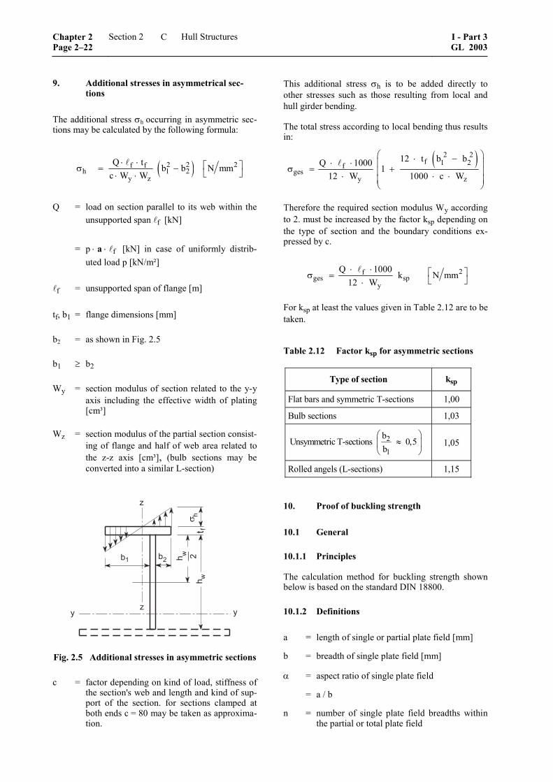
9. Additional stresses in asymmetrical sec-tions
The additional stress σh occurring in asymmetric sec-tions may be calculated by the following formula:
( )2 2 2f fh 1 2
y z
Q t b b N mmc W W
⋅ ⋅ ⎡ ⎤σ = − ⎣ ⎦⋅ ⋅
Q = load on section parallel to its web within the unsupported span f [kN]
= p ⋅ a ⋅ f [kN] in case of uniformly distrib-uted load p [kN/m²]
f = unsupported span of flange [m]
tf, b1 = flange dimensions [mm]
b2 = as shown in Fig. 2.5
b1 ≥ b2
Wy = section modulus of section related to the y-y axis including the effective width of plating [cm³]
Wz = section modulus of the partial section consist-ing of flange and half of web area related to the z-z axis [cm³], (bulb sections may be converted into a similar L-section)
��
�
��
�
� �
� � �� �
� �
Fig. 2.5 Additional stresses in asymmetric sections
c = factor depending on kind of load, stiffness of the section's web and length and kind of sup-port of the section. for sections clamped at both ends c = 80 may be taken as approxima-tion.
This additional stress σh is to be added directly to other stresses such as those resulting from local and hull girder bending.
The total stress according to local bending thus results in:
( )2 2f 1 2f
gesy z
12 t b bQ 1000 112 W 1000 c W
⎛ ⎞⋅ −⋅ ⋅ ⎜ ⎟σ = +⎜ ⎟⋅ ⋅ ⋅⎜ ⎟⎝ ⎠
Therefore the required section modulus Wy according to 2. must be increased by the factor ksp depending on the type of section and the boundary conditions ex-pressed by c.
2fges sp
y
Q 1000 k N mm12 W⋅ ⋅ ⎡ ⎤σ = ⎣ ⎦⋅
For ksp at least the values given in Table 2.12 are to be taken.
Table 2.12 Factor ksp for asymmetric sections
Type of section ksp
Flat bars and symmetric T-sections 1,00
Bulb sections 1,03
2
1
bUnsymmetric T-sections 0,5
b⎛ ⎞
≈⎜ ⎟⎝ ⎠
1,05
Rolled angels (L-sections) 1,15
10. Proof of buckling strength
10.1 General
10.1.1 Principles
The calculation method for buckling strength shown below is based on the standard DIN 18800.
10.1.2 Definitions
a = length of single or partial plate field [mm]
b = breadth of single plate field [mm]
α = aspect ratio of single plate field
= a / b
n = number of single plate field breadths within the partial or total plate field
Chapter 2 Page 2–22
Section 2 Hull Structures I - Part 3GL 2003
C
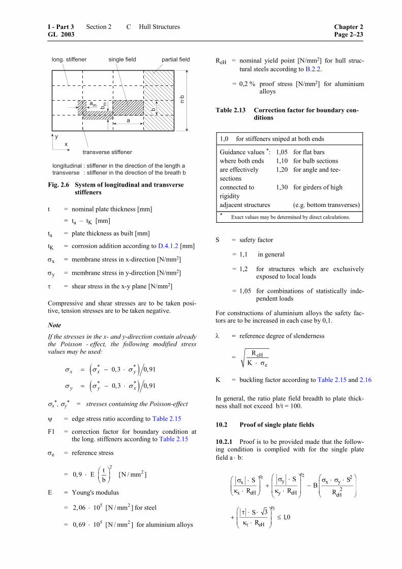
�
�
�� � �
��
��
������������ �������������
���
���������������
����� ��������������
������!������"������������������������������������������������ ����� "�������������������������������������������
Fig. 2.6 System of longitudinal and transverse stiffeners
t = nominal plate thickness [mm]
= ta – tK [mm]
ta = plate thickness as built [mm]
tK = corrosion addition according to D.4.1.2 [mm]
σx = membrane stress in x-direction [N/mm2]
σy = membrane stress in y-direction [N/mm2]
τ = shear stress in the x-y plane [N/mm2]
Compressive and shear stresses are to be taken posi-tive, tension stresses are to be taken negative.
Note
If the stresses in the x- and y-direction contain already the Poisson - effect, the following modified stress values may be used:
( )( )
* *
* *
0,3 0,91
0,3 0,91
= − ⋅
= − ⋅
x x y
y y x
σ σ σ
σ σ σ
σx*, σy* = stresses containing the Poisson-effect
ψ = edge stress ratio according to Table 2.15
F1 = correction factor for boundary condition at the long. stiffeners according to Table 2.15
σe = reference stress
= 2
2t0,9 E [N / mm ]b
⎛ ⎞⋅ ⎜ ⎟⎝ ⎠
E = Young's modulus
= 5 22,06 10 [N / mm ]⋅ for steel
= 5 20,69 10 [N / mm ]⋅ for aluminium alloys
ReH = nominal yield point [N/mm2] for hull struc-tural steels according to B.2.2.
= 0,2 % proof stress [N/mm2] for aluminium alloys
Table 2.13 Correction factor for boundary con-ditions
1,0 for stiffeners sniped at both ends
Guidance values *: 1,05 for flat bars where both ends 1,10 for bulb sections are effectively 1,20 for angle and tee-sections connected to 1,30 for girders of high rigidity adjacent structures (e.g. bottom transverses)* Exact values may be determined by direct calculations.
S = safety factor
= 1,1 in general
= 1,2 for structures which are exclusively exposed to local loads
= 1,05 for combinations of statistically inde-pendent loads
For constructions of aluminium alloys the safety fac-tors are to be increased in each case by 0,1.
λ = reference degree of slenderness
= eH
e
RK ⋅ σ
K = buckling factor according to Table 2.15 and 2.16
In general, the ratio plate field breadth to plate thick-ness shall not exceed b/t = 100.
10.2 Proof of single plate fields
10.2.1 Proof is to be provided made that the follow-ing condition is complied with for the single plate field a ⋅ b:
21
3
ee 2y x yx
2x eH y eH eH
e
eH
S SSB
R R R
3S1,0
Rτ
⎛ ⎞ ⎛ ⎞σ ⋅ σ ⋅ σ ⋅⎛ ⎞σ ⋅ ⎜ ⎟ ⎜ ⎟+ −⎜ ⎟⎜ ⎟ ⎜ ⎟ ⎜ ⎟κ ⋅ κ ⋅⎝ ⎠ ⎝ ⎠⎝ ⎠
⎛ ⎞τ ⋅ ⋅⎜ ⎟+ ≤⎜ ⎟κ ⋅⎝ ⎠
I - Part 3 GL 2003
Section 2 Hull Structures Chapter 2Page 2–23
C
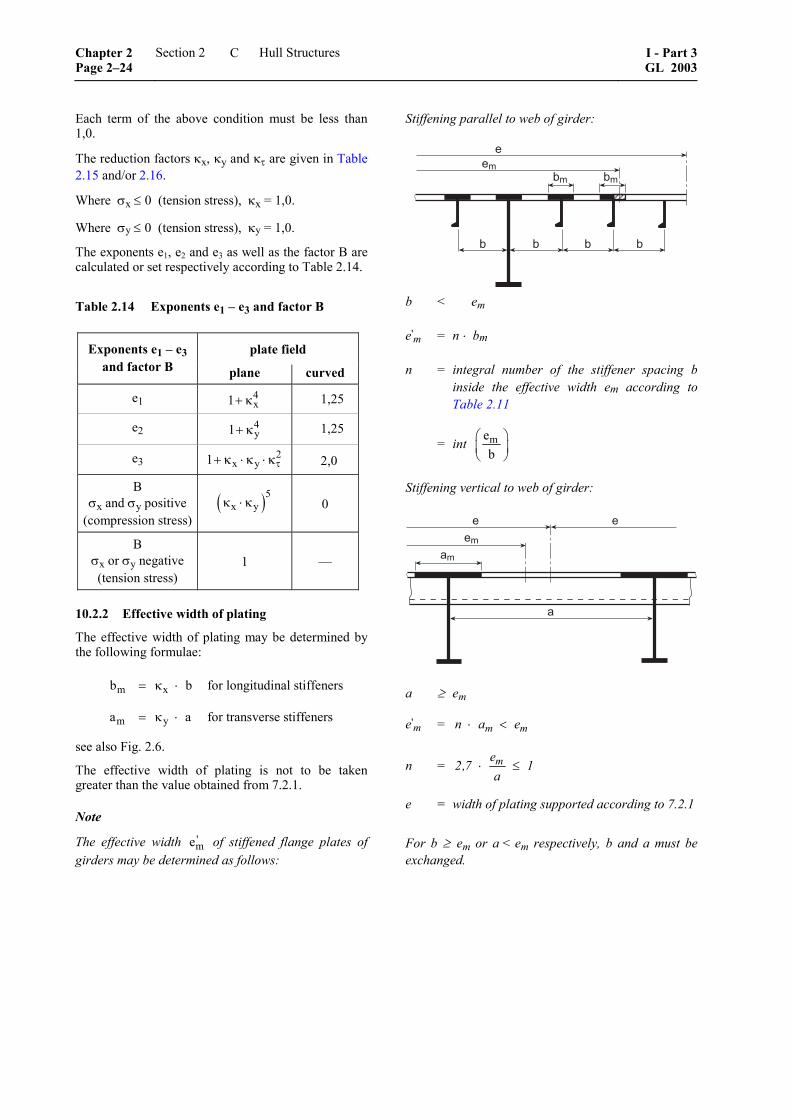
Each term of the above condition must be less than 1,0.
The reduction factors κx, κy and κτ are given in Table 2.15 and/or 2.16.
Where σx ≤ 0 (tension stress), κx = 1,0.
Where σy ≤ 0 (tension stress), κy = 1,0.
The exponents e1, e2 and e3 as well as the factor B are calculated or set respectively according to Table 2.14.
Table 2.14 Exponents e1 – e3 and factor B
plate field Exponents e1 – e3 and factor B plane curved
e1 4x1+ κ 1,25
e2 4y1+ κ 1,25
e3 2x y1 τ+ κ ⋅ κ ⋅ κ 2,0
B σx and σy positive
(compression stress) ( )5
x yκ ⋅ κ 0
B σx or σy negative (tension stress)
1 ––
10.2.2 Effective width of plating
The effective width of plating may be determined by the following formulae:
m xb b= κ ⋅ for longitudinal stiffeners
m ya a= κ ⋅ for transverse stiffeners
see also Fig. 2.6.
The effective width of plating is not to be taken greater than the value obtained from 7.2.1.
Note
The effective width 'me of stiffened flange plates of girders may be determined as follows:
Stiffening parallel to web of girder:
���
�� ��
� � � �
b < em
e'm = n ⋅ bm
n = integral number of the stiffener spacing b inside the effective width em according to Table 2.11
= int meb
⎛ ⎞⎜ ⎟⎝ ⎠
Stiffening vertical to web of girder:
����
� �
�
a ≥ em
e'm = m mn a e⋅ <
n = ⋅ ≤me2,7 1
a
e = width of plating supported according to 7.2.1
For b ≥ em or a < em respectively, b and a must be exchanged.
Chapter 2 Page 2–24
Section 2 Hull Structures I - Part 3GL 2003
C
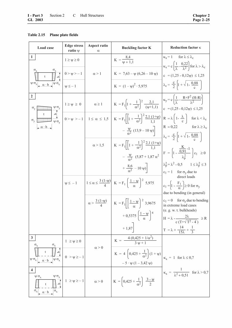
Table 2.15 Plane plate fields
��
����������������������
�������������
��������������������� �������
��������������
������������������������
��������������������������
��������������������������������� ��
��������������������������������� ���
����������������������������������
���������������
�����������
��
��
�����
�����
�
�������� ����� �� ������
�������������� �� �������������� ��
���������
����������
������
����
�����������
�����������
�������
����
�������������
������
������
����
�
�
����� ��������
�� ��
� �����
�������������������������
����������������� ��
���������
�
�
�
�������
�����
�� �������������������
�� �������������������������������
� �����������������������
�� �����������������
������
��
�
����
������
�
����
�����������
�
�
���� ��� �������
! ����������������������������������"
�� �������������
"����!�"���
� �����������������������
" ���������������������������#�����
" �������������������������������
�$ ��� �������������������$������
�� ��� �������%&'���%(�'���)�*%+
�� ��� �������%&'�����',%(,-(,�'���'.'�)�*%��*+'+'/�-/�0/��/��&)12'*%+�
�� �������������������
�����
����������������������
��
���������
�������
��
�����
�$�
� ����������������������������������
��� �
��
�� �������������������������
%&'�����',%(,-�(,�-','�*)�
��
�����
���������������������������������
�������������������������
�
� �������
� ��������
����
����
�
� ��������
�������
��������
��
� �
�����������3���������
�������������� �
�����
��
��������
��
� �
�� ���� �����������
�� �����������������������������������
� �������������
�
������ �����
I - Part 3 GL 2003
Section 2 Hull Structures Chapter 2Page 2–25
C
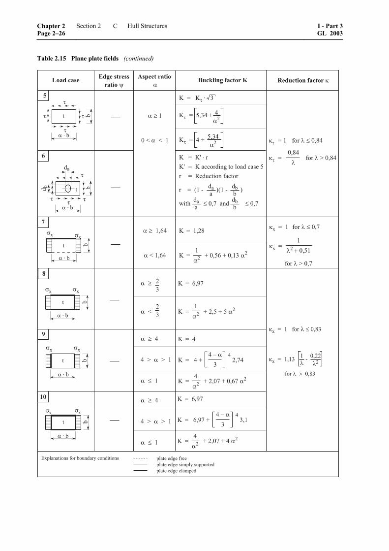
Table 2.15 Plane plate fields (continued)
�������� ����� �� ������
������ �����
�������������� �� �������������� ��
� ���������������������������
0(�2���������������*,%���������������
�
�
�
� �
�����
�
%*
% �
� ��
�
�����
� �
�����
�
�� ��
�
� �������
� ��������������������������
�
�
����
��#���#���
��������
�#�����
�������������
����������
��
�����
�
�
����������������
%**
� ����4�����4 �����*����%(,-����)�*%��*+'��� ���"'%&��(�,��*����
%��
%**
%��
�� ��� ������������
�� �������������������������������
�
�����
�
�� ��
�
�����
� �
����
�����
�
�� ��
�
� ����� �
� ����������������������
� ����
� �����������������������������
� ��������������������������
�
���
�
� ����� �
� ������ ������������������������
� �����������������������
�
���
�
�
��#
��
��
����
������������
������
����
������������
������
!
�"
���������������
���������������������
������
�������� �����������
$)*�'�'%-'���''$)*�'�'%-'�+(.$)��+&$$���'%$)*�'�'%-'��)*.$'%
5�$)*,*�(�,+�������&,%*�����,%(�(�,+
�� ���� �����������
�� �
���������������
�
� �������
Chapter 2 Page 2–26
Section 2 Hull Structures I - Part 3GL 2003
C

Table 2.16 Curved plate field R/t ≤ 2500 1
�������� ������ ����#�$��
�������������� �� �������������� ��
��
��������
"
"
�
"
��������
�
"
�� ���� �
���������������
�� �����������������
������������#��������
�� �
���������������
����
�
�� ����� �
������������������
�� ������������� �����������������#�������
��� �������3���
����������#���������
�� ��������3���
����������������
"�
��
�
��
�������
"
�������
"
"
�
"
����������
�����������������������������
��������������
�
�
��
"����
��
"����
�
"
�
"
��
"����
��
"�
�
��
�� ����
����������������
�� �����������������
������������#���������
�� �
���������������
����
�
*+�(,�)�*%��*+'��*
�������������
"���"����
"
�������
�
"
"
�������
�
"
���������������������������������������������
"����������"
�
�
�
"�
�
$'
�����$'���"�
0(�2
"�
��
���
�#
����������������������������������������"�����
������
"����
�������������������������������������������
"�"�
�����
�
�
��
"
"
�
��
"
"
�
���������������������������������������"����
�
�������
"����
"����
��
���������������������� ������������������"�
�����
��
"�
�
$)*�'�'%-'���''$)*�'�'%-'�+(.$)��+&$$���'%$)*�'�'%-'��)*.$'%
5�$)*,*�(�,+�������&,%*�����,%(�(�,+6
����������������
$'���'��'�,*)�$�'++&�'�(,783..�9
�������&�:'%�$)*�'��(')%+�0(�2�*�:'���)*�-'��*%(&+��2'���:*)&'�,''%�,�������'��*1',�)'++��2*,��,'�%'�(:'%������2'�'�$*,%'%�$)*,'��(')%/
�������&�:'%�+(,-)'��(')%+/�'/-/��2'��()-'�+��*1'��02(�2�*�'�)��*�'%�0(�2(,�$)*,'�$*��(*)�������*)��(')%+���2'��'%&��(�,��*�������.*���*1',����*+���))�06
���;�*%��*+'���6���������3��������6����)�*%��*+'��6����������3�
�������
I - Part 3 GL 2003
Section 2 Hull Structures Chapter 2Page 2–27
C

10.2.3 Webs and flanges
For non-stiffened webs and flanges of sections and girders proof of sufficient buckling strength as for single plate fields is to be provided according to 10.2.1.
Note
Within 0,6 L amidships the following guidance values are recommended for the ratio web depth to web thickness and/or flange breadth to flange thickness:
≤w
w
hflat bars: 19,5 k
t
angle, tee and bulb sections:
≤w
w
hweb: 60,0 k
t
≤i
f
bflange: 19,5 k
t
bi = b1 or b2 according to Fig. 2.7, the larger value is to be taken.
10.3 Proof of partial and total fields
10.3.1 Longitudinal and transverse stiffeners
Proof is to be provided that the continuous longitudi-nal and transverse stiffeners of partial and total plate fields comply with the conditions set out in 10.3.2 and 10.3.3.
10.3.2 Lateral buckling
a b
eHS 1
Rσ + σ
≤
σa = uniformly distributed compressive stress in the direction of the stiffener axis [N/mm²]
= σx for longitudinal stiffeners
= σy for transverse stiffeners
σb = bending stress in the stiffeners
= 2o 13
st
M M[N / mm ]
W 10+
⋅
Mo = bending moment due to deformation w of stiffener
= [ ]zKi
f z
p wF N mm
c p⋅
⋅−
( )f zc p 0− >
M1 = bending moment due to the lateral load p
for continuous longitudinal stiffeners:
= [ ]2
3p b a
N mm24 10
⋅ ⋅⋅
⋅
for transverse stiffeners:
= ( ) [ ]
2
3s
p a n bN mm
c 8 10
⋅ ⋅⋅
⋅ ⋅
p = lateral load [kN/m²]
FKi = ideal buckling force of the stiffener [N]
FKix = 2
4x2 E I 10
aπ
⋅ ⋅ for long. stiffeners
FKiy = ( )
24
y2 E I 10n b
π⋅ ⋅ ⋅
⋅ for transv. stiffeners
Ix, Iy = moments of inertia of the longitudinal or transverse stiffener including effective width of plating according to 10.2.2 [cm4]
Ix ≥ 3
4b t
12 10⋅
⋅
yI ≥ 3
4a t
12 10⋅
⋅
pz = nominal lateral load of the stiffener due to σx, σy and τ [N/mm²]
for longitudinal stiffeners:
2
azx x1 y y 1
t bp 2 c 2b a
⎛ ⎞π ⋅⎛ ⎞⎜ ⎟= σ + ⋅ ⋅ σ + τ⎜ ⎟⎜ ⎟⎝ ⎠⎝ ⎠
for transverse stiffeners:
2
yazy x x1 y 1
a
At ap 2 c 1 2a n b a t
⎛ ⎞⎛ ⎞⎛ ⎞π⋅⎜ ⎟= ⋅ ⋅σ + σ + + τ⎜ ⎟⎜ ⎟ ⎜ ⎟⎜ ⎟⋅ ⋅⎝ ⎠ ⎝ ⎠⎝ ⎠
xx1 x
a
A1b t
⎛ ⎞σ = σ +⎜ ⎟⋅⎝ ⎠
cx, cy = factor taking into account the stresses ver-tical to the stiffener's axis and distributed variable along the stiffener's length
= ( )0,5 1 for 0 1+ ψ ≤ ψ ≤
= 0,5 for 01
ψ <− ψ
ψ = edge stress ratio according to Table 2.15
Ax, Ay = sectional area of the longitudinal or trans-verse stiffener respectively [mm2]
Chapter 2 Page 2–28
Section 2 Hull Structures I - Part 3GL 2003
C

1 21 eH 2 2
m m= t R E 0a b
τ⎡ ⎤⎛ ⎞⎢ ⎥τ − ⋅ + ≥⎜ ⎟⎢ ⎥⎝ ⎠⎣ ⎦
for longitudinal stiffeners:
1 2
1 2
a 2,0 : m 1,47 m 0,49ba 2,0 : m 1,96 m 0,37b
≥ = =
< = =
for transverse stiffeners:
1 2 2
1 2 2
a 1,960,5 : m 0,37 mn b n
a 1,470,5 : m 0,49 mn b n
≥ = =⋅
< = =⋅
w = wo + w1
wo = assumed imperfection [mm]
oxa bw for long. stiffeners
250 250≥ ≤
oyn b aw for transv. stiffeners250 250
⋅≥ ≤
however wo ≤ 10 mm
Note
For stiffeners sniped at both ends wo must not be taken less than the distance from the midpoint of plat-ing to the neutral axis of the profile including effective width of plating.
w1 = deformation of stiffener due to lateral load p at midpoint of stiffener span [mm]
In case of uniformly distributed load the following values for w1 may be used:
4
1 7x
for longitudinal stiffeners:
p b aw =384 10 E I
⋅ ⋅
⋅ ⋅ ⋅
( )4
1 7 2y s
for transverse stiffeners:
5 a p n bw =
384 10 E I c
⋅ ⋅ ⋅
⋅ ⋅ ⋅ ⋅
cf = elastic support provided by the stiffener [N/mm²]
cfx = ( )2
Kix px2F 1 c for long. stiffenersaπ
⋅ ⋅ +
cpx = 4
x3
x
1
12 10 I0,91 1t b
1c α
⎛ ⎞⋅ ⋅⋅ −⎜ ⎟
⋅⎝ ⎠+
cxα = 2
a 2 b for a 2 b2 b a
⎡ ⎤+ ≥⎢ ⎥
⎣ ⎦
=
22a
1 for a 2 b2 b
⎡ ⎤⎛ ⎞⎢ ⎥+ <⎜ ⎟⎢ ⎥⎝ ⎠⎣ ⎦
fyc = ( )
( )2
s Kiy py2c F 1 cn b
π⋅ ⋅ ⋅ +
⋅
for transv. stiffeners
cs = factor accounting for the boundary conditions of the transverse stiffener
= 1,0 for simply supported stiffeners
= 2,0 for partially constraint stiffeners
cpy = 4
y3
y
1
12 10 I0,91 1
t a1
c α
⎛ ⎞⋅ ⋅⋅ −⎜ ⎟
⎜ ⎟⋅⎝ ⎠+
cyα = 2
n b 2 a for n b 2 a2 a n b
⎡ ⎤⋅+ ⋅ ≥⎢ ⎥⋅⎣ ⎦
=
22n b
1 for n b 2 a2 a
⎡ ⎤⎛ ⎞⋅⎢ ⎥+ ⋅ <⎜ ⎟⎢ ⎥⎝ ⎠⎣ ⎦
Wst = section modulus of stiffener (long. or trans-verse) [cm³] including effective width of plating according to 10.2.2
If no lateral load p is acting the bending stress σb is to be calculated at the midpoint of the stiffener span for that fibre which results in the largest stress value. If a lateral load p is acting, the stress calculation is to be carried out for both fibres of the stiffener's cross sec-tional area (if necessary for the biaxial stress field at the plating side).
Note Longitudinal and transverse stiffeners not subjected to lateral load p have sufficient scantlings if their mo-ments of inertia Ix and Iy are not less than obtained by the following formulae:
( ) ( )
2 24ox wzx
x 2 4 2eHx
2 2zy oy w 4
y 2 4 2eHy
w hp a aI cmR10 E
S
p n b w h n bI cm
R10 ES
⎛ ⎞⎜ ⎟⋅⋅ ⎡ ⎤= +⎜ ⎟ ⎣ ⎦π ⋅ π ⋅⎜ ⎟− σ⎜ ⎟⎝ ⎠
⎛ ⎞⎜ ⎟⋅ ⋅ ⋅ ⋅ ⎡ ⎤= +⎜ ⎟ ⎣ ⎦π ⋅ π ⋅⎜ ⎟− σ⎜ ⎟⎝ ⎠
I - Part 3 GL 2003
Section 2 Hull Structures Chapter 2Page 2–29
C
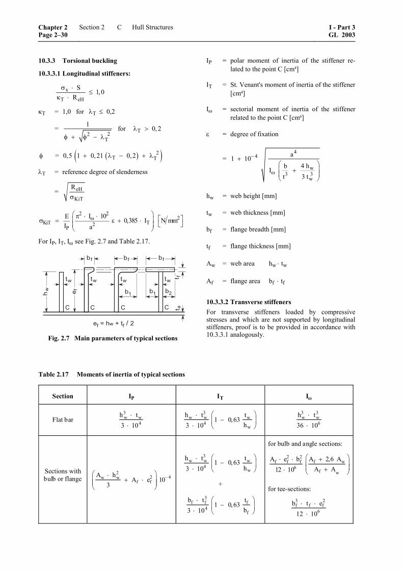
10.3.3 Torsional buckling
10.3.3.1 Longitudinal stiffeners:
x
T eH
S 1,0R
σ ⋅≤
κ ⋅
κT = 1,0 for λT ≤ 0,2
= T22T
1 for 0, 2λ >φ + φ − λ
( )( )2T T= 0,5 1 0,21 0,2φ + λ − + λ
λT = reference degree of slenderness
= eH
KiT
Rσ
2 22
KiT T2P
I 10E 0,385 I N mmI a
ω⎛ ⎞π ⋅ ⋅ ⎡ ⎤⎜ ⎟σ = ε + ⋅ ⎣ ⎦⎜ ⎟⎝ ⎠
For IP, IT, Iω see Fig. 2.7 and Table 2.17.
��
��
�� �� ��
�� �� ��
� �� �
��
������������#��
$ $ $ $
�� ����
Fig. 2.7 Main parameters of typical sections
IP = polar moment of inertia of the stiffener re-lated to the point C [cm4]
IT = St. Venant's moment of inertia of the stiffener [cm4]
Iω = sectorial moment of inertia of the stiffener related to the point C [cm6]
ε = degree of fixation
= 4
4
w3 3
w
a1 104 hbI
t 3 t
−
ω
+⎛ ⎞
+⎜ ⎟⎜ ⎟⎝ ⎠
hw = web height [mm]
tw = web thickness [mm]
bf = flange breadth [mm]
tf = flange thickness [mm]
Aw = web area hw ⋅ tw
Af = flange area bf ⋅ tf
10.3.3.2 Transverse stiffeners For transverse stiffeners loaded by compressive stresses and which are not supported by longitudinal stiffeners, proof is to be provided in accordance with 10.3.3.1 analogously.
Table 2.17 Moments of inertia of typical sections
Section IP IT Iω
Flat bar 3w w
4h t3 10
⋅
⋅
3w w w
4w
h t t1 0,63
h3 10
⎛ ⎞⋅−⎜ ⎟
⋅ ⎝ ⎠
3 3w w
6h t36 10
⋅
⋅
Sections with bulb or flange
22 4w w
f fA h
A e 103
−⎛ ⎞⋅+ ⋅⎜ ⎟⎜ ⎟
⎝ ⎠
3w w w
4w
h t t1 0,63h3 10
⎛ ⎞⋅−⎜ ⎟
⋅ ⎝ ⎠
+
3f f f
4f
b t t1 0,63
b3 10⎛ ⎞⋅
−⎜ ⎟⋅ ⎝ ⎠
for bulb and angle sections:
2 2f wf f f
6f w
A 2,6 AA e bA A12 10
⎛ ⎞+⋅ ⋅⎜ ⎟⎜ ⎟+⋅ ⎝ ⎠
for tee-sections:
3 2f f f
6b t e
12 10⋅ ⋅
⋅
Chapter 2 Page 2–30
Section 2 Hull Structures I - Part 3GL 2003
C
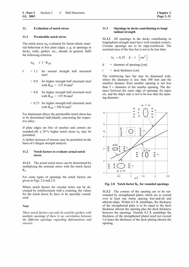
11. Evaluation of notch stress
11.1 Permissible notch stress
The notch stress σK evaluated for linear-elastic mate-rial behaviour at free plate edges, e. g. at openings in decks, walls, girders, etc., should, in general, fulfil the following criterion:
K eHf Rσ ≤ ⋅
f = 1,1 for normal strength hull structural steel
= 0,9 for higher strength hull structural steel with ReH = 315 N/mm2
= 0,8 for higher strength hull structural steel with ReH = 355 N/mm2
= 0,73 for higher strength hull structural steel with ReH = 390 N/mm2
For aluminium alloys the permissible notch stress has to be determined individually concerning the respec-tive alloy.
If plate edges are free of notches and corners are rounded-off, a 20 % higher notch stress σK may be permitted. A further increase of stresses may be permitted on the basis of a fatigue strength analysis.
11.2 Notch factors to evaluate actual notch stress
11.2.1 The actual notch stress can be determined by multiplying the nominal stress with the notch factor Kt.
For some types of openings the notch factors are given in Figs. 2.8 and 2.9.
Where notch factors for circular holes can be de-creased by reinforcement with a coaming, the values for the notch factor Kt have to be specially consid-ered.
Note
These notch factors can only be used for girders with multiple openings if there is no correlation between the different openings regarding deformations and stresses.
11.3 Openings in decks contributing to longi-tudinal strength
11.3.1 All openings in the decks contributing to longitudinal strength must have well rounded corners. Circular openings are to be edge-reinforced. The sectional area of the face bar is not to be less than:
2fA 0, 25 d t cm⎡ ⎤= ⋅ ⋅ ⎣ ⎦
d = diameter of openings [cm]
t = deck thickness [cm]
The reinforcing face bar may be dispensed with, where the diameter is less than 300 mm and the smallest distance from another opening is not less than 5 × diameter of the smaller opening. The dis-tance between the outer edge of openings for pipes etc. and the ship's side is not to be less than the open-ing diameter.
�%&' � �&' �
(
�
'
�
�
�
�
�
)�
�#�&'
*��
��
��
��
��
Fig. 2.8 Notch factor Kt for rounded openings
11.3.2 The corners of the opening are to be sur-rounded by strengthened plates which are to extend over at least one frame spacing fore-and-aft and athwart-ships. Within 0,5 L amidships, the thickness of the strengthened plate is to be equal to the deck thickness abreast the opening plus the deck thickness between the openings. Outside 0,5 L amidships the thickness of the strengthened plated need not exceed 1,6 times the thickness of the deck plating abreast the opening.
I - Part 3 GL 2003
Section 2 Hull Structures Chapter 2Page 2–31
C

��������
������
���������
�������
�����������������
�������������������
���
���
���
���������
�����!������"�
� ��� ��
�� ��
�
���
��
�������
������
���������
���������������������������������
�������������������
���
���
���
���������
�����!������"�
� �
Fig. 2.9 Notch factor Kt for rectangular openings with rounded corners at uniaxial state of stresses (left) and at multiaxial state of stresses (right)
11.3.3 The hatchway corner radius is not to be less than:
br n b 1⎛ ⎞= ⋅ −⎜ ⎟⎝ ⎠B
minr 0,1 m=
n = 1200
nmin = 0,1
nmax = 0,25
= length of opening in [m]
b = breadth in [m], of the opening or total breadth of openings in case of more than one. b/B need not to be taken smaller than 0,4.
11.3.4 Where the corners of openings are elliptic or parabolic, strengthening according to 11.3.2 is not required. The dimensions of the elliptical and para-bolical corners shall be as shown in Fig. 2.10:
*
�
*������������*����%(,-�����/�
Fig. 2.10 Dimension of elliptical or parabolical
corners
Where smaller values are taken for a and c, reinforced insert plates are required which will be considered in each individual case.
11.4 Actual notch stress calculated by FEM methods
An exact distribution of notch stresses can be evalu-ated by means of finite element calculations. For fa-tigue investigations the stress increase due to geome-try of cut-outs has to be considered.
Chapter 2 Page 2–32
Section 2 Hull Structures I - Part 3GL 2003
C
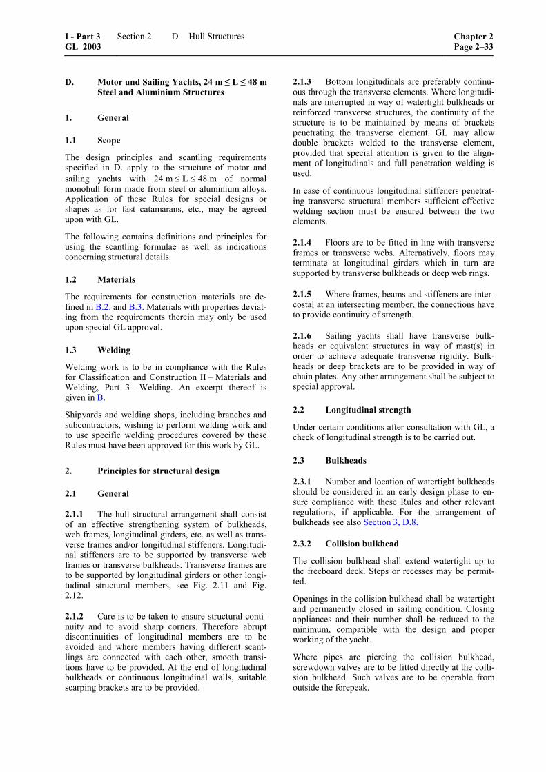
D. Motor und Sailing Yachts, 24 m ≤ L ≤ 48 m Steel and Aluminium Structures
1. General
1.1 Scope
The design principles and scantling requirements specified in D. apply to the structure of motor and sailing yachts with 24 m ≤ L ≤ 48 m of normal monohull form made from steel or aluminium alloys. Application of these Rules for special designs or shapes as for fast catamarans, etc., may be agreed upon with GL.
The following contains definitions and principles for using the scantling formulae as well as indications concerning structural details.
1.2 Materials
The requirements for construction materials are de-fined in B.2. and B.3. Materials with properties deviat-ing from the requirements therein may only be used upon special GL approval.
1.3 Welding
Welding work is to be in compliance with the Rules for Classification and Construction II – Materials and Welding, Part 3 – Welding. An excerpt thereof is given in B.
Shipyards and welding shops, including branches and subcontractors, wishing to perform welding work and to use specific welding procedures covered by these Rules must have been approved for this work by GL.
2. Principles for structural design
2.1 General
2.1.1 The hull structural arrangement shall consist of an effective strengthening system of bulkheads, web frames, longitudinal girders, etc. as well as trans-verse frames and/or longitudinal stiffeners. Longitudi-nal stiffeners are to be supported by transverse web frames or transverse bulkheads. Transverse frames are to be supported by longitudinal girders or other longi-tudinal structural members, see Fig. 2.11 and Fig. 2.12.
2.1.2 Care is to be taken to ensure structural conti-nuity and to avoid sharp corners. Therefore abrupt discontinuities of longitudinal members are to be avoided and where members having different scant-lings are connected with each other, smooth transi-tions have to be provided. At the end of longitudinal bulkheads or continuous longitudinal walls, suitable scarping brackets are to be provided.
2.1.3 Bottom longitudinals are preferably continu-ous through the transverse elements. Where longitudi-nals are interrupted in way of watertight bulkheads or reinforced transverse structures, the continuity of the structure is to be maintained by means of brackets penetrating the transverse element. GL may allow double brackets welded to the transverse element, provided that special attention is given to the align-ment of longitudinals and full penetration welding is used.
In case of continuous longitudinal stiffeners penetrat-ing transverse structural members sufficient effective welding section must be ensured between the two elements.
2.1.4 Floors are to be fitted in line with transverse frames or transverse webs. Alternatively, floors may terminate at longitudinal girders which in turn are supported by transverse bulkheads or deep web rings.
2.1.5 Where frames, beams and stiffeners are inter-costal at an intersecting member, the connections have to provide continuity of strength.
2.1.6 Sailing yachts shall have transverse bulk-heads or equivalent structures in way of mast(s) in order to achieve adequate transverse rigidity. Bulk-heads or deep brackets are to be provided in way of chain plates. Any other arrangement shall be subject to special approval.
2.2 Longitudinal strength
Under certain conditions after consultation with GL, a check of longitudinal strength is to be carried out.
2.3 Bulkheads
2.3.1 Number and location of watertight bulkheads should be considered in an early design phase to en-sure compliance with these Rules and other relevant regulations, if applicable. For the arrangement of bulkheads see also Section 3, D.8.
2.3.2 Collision bulkhead
The collision bulkhead shall extend watertight up to the freeboard deck. Steps or recesses may be permit-ted.
Openings in the collision bulkhead shall be watertight and permanently closed in sailing condition. Closing appliances and their number shall be reduced to the minimum, compatible with the design and proper working of the yacht.
Where pipes are piercing the collision bulkhead, screwdown valves are to be fitted directly at the colli-sion bulkhead. Such valves are to be operable from outside the forepeak.
I - Part 3 GL 2003
Section 2 Hull Structures Chapter 2Page 2–33
D
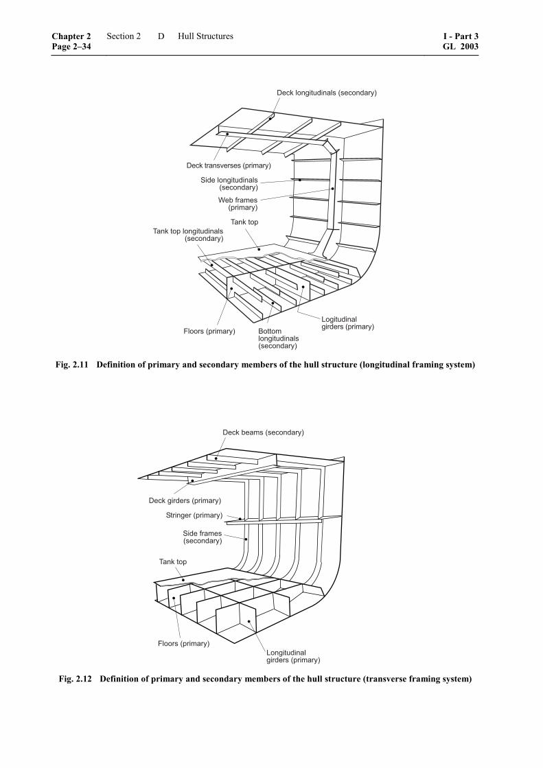
#��$� �����%&��� '�('����&���)
#��$�����'*��'�'�(���+���)
,�&�� �����%&��� '('����&���)
-�.�!��+�'(���+���)
/��$����/��$����� �����%&��� '
('����&���)
� ���'�(���+���) 0����+ �����%&��� '('����&���)
1����%&��� ���&��'�(���+���)
Fig. 2.11 Definition of primary and secondary members of the hull structure (longitudinal framing system)
#��$�.��+'�('����&���)
#��$����&��'�(���+���)
,��������(���+���)
/��$����
� ���'�(���+���)1�����%&��� ���&��'�(���+���)
,�&��!��+�'('����&���)
Fig. 2.12 Definition of primary and secondary members of the hull structure (transverse framing system)
Chapter 2 Page 2–34
Section 2 Hull Structures I - Part 3GL 2003
D
2.3.3 Stern tube bulkhead
All yachts are to have a stern tube bulkhead which is, in general, to be so arranged that the stern tube and the rudder trunk are enclosed in a watertight compart-ment. The stern tube bulkhead shall extend to the freeboard deck or to a watertight platform situated above the load waterline.
Where a complete stern tube bulkhead is not practica-ble, only watertight void spaces enclosing the stern tube entrance, providing the possibility for a second watertight sealing may be provided after agreement with GL. The same arrangement can be applied for the rudder trunk.
2.3.4 Remaining watertight bulkheads
Remaining watertight bulkheads are, depending on the type of the yacht and the Classification for damage stability, to extend to the freeboard deck. Wherever practicable, they shall be arranged in one transverse plane, otherwise those portions of decks situated be-tween parts of transverse bulkheads are to be water-tight.
It is recommended that bulkheads shall be fitted sepa-rating the machinery space from service spaces and accommodation rooms forward and aft and made watertight and gastight up to the freeboard deck.
2.3.5 Bulkhead stiffening
Bulkhead stiffening members are to be located in way of hull and deck longitudinal girders or stiffeners respectively. Where vertical stiffeners are cut in way of watertight doors, reinforced stiffeners are to be fitted on each side of the door opening and crossbars are to be provided to support the cut-off stiffeners.
2.3.6 Openings in watertight bulkheads
2.3.6.1 Type and arrangement of doors are to be submitted for approval.
In watertight bulkheads other than collision bulkheads, watertight doors may be fitted. Below the deepest load waterline, they are to be constructed as sliding doors, exemptions may be granted on case by case. Above that waterline, hinged doors may be approved.
Watertight doors are to be sufficiently strong and of an approved design. The thickness of plating is not to be less than the minimum thickness according to 4.3.
Openings for watertight doors in the bulkheads are to be effectively framed such as to facilitate proper fit-ting of the doors and to guarantee watertightness.
2.3.6.2 Watertight bulkhead doors and their frames, are to be tested before they are fitted onboard by a head of water corresponding to the freeboard deck height or the results from damage stability calculation. Alternatively watertight doors may be used which have been type approved in accordance with GL spe-
cial acceptance procedure. After having been fitted on board, the doors are to be soap-tested for tightness and to be subject to an operational test.
2.3.6.3 Penetrations through watertight bulkheads
Where bulkhead fittings are penetrating watertight bulkheads, care is to be taken to maintain watertight-ness. For penetrations through the collision bulkhead 2.3.2 is to be observed.
2.4 Openings
2.4.1 In highly stressed areas openings are to be generally avoided.
Bulwark openings shall not be located at ends of su-perstructures.
2.4.2 Corners of all openings in strength structures are to be well rounded. If necessary, the shape of the openings is to be designed to reduce stress concentra-tions.
2.5 Side doors
2.5.1 In general, doors in the side shell shall not extend below the load waterline.
2.5.2 Door openings in the shell are to have well rounded corners and adequate compensation of the opening is to be arranged with web frames at sides and stringers above and below. In general the strength of side doors is to be equivalent to the strength of the surrounding structure.
2.5.3 Doors shall preferably be designed to open outwards.
2.6 Bottom structure
2.6.1 Generally, a centreline girder shall be fitted for docking purposes unless sufficient strength and stiffness is already achieved by the external keel or the bottom shape. Additional bottom girders may be ap-propriate. The centreline and the off-centreline bottom girders are to extend as far forward and aft as practi-cable. The girders shall be fitted with a continuous face plate.
Lightening holes in girders shall generally not exceed half the depth of the girder and their length shall not exceed half the frame spacing.
2.6.2 Floors or equivalent structural components are to be fitted in the area of the engine foundations, the rudder skeg and the propeller bracket, if applica-ble. Plating is to be locally increased in way of rudder bearings, propeller brackets and stabilizers by 1,5 times of the adjacent plate thickness.
2.6.3 Manholes and other openings are not to be located at the ends of floor or girder spans, unless shear stress checks are carried out in such areas.
I - Part 3 GL 2003
Section 2 Hull Structures Chapter 2Page 2–35
D
2.6.4 In case of sailing yachts with ballast keel, the bottom structure is to be reinforced due to additional loads transmitted by the keel. Special care is to be taken with the structural support of fin keel’s leading and trailing edge.
2.7 Engine foundation
The foundation shall be constructed for the proper transmission of forces in the transverse and longitudi-nal directions. Longitudinal girders forming seatings of the engine, the gearbox and the thrust block shall therefore extend to the engine room bulkheads and are to be supported transversely by floors, web frames or wing bulkheads. Floors in the engine room are gener-ally to be fitted at every frame. Additional intermedi-ate frames may be appropriate.
2.8 Side structure and bulwarks
2.8.1 Side frames shall be connected to keel floors and deck beams by brackets. Alternatively, a continu-ous transition between such elements is to be ade-quately rounded.
Continuity of longitudinal stiffeners is to be ensured, if applicable.
2.8.2 Bulwark plating is to be determined by apply-ing the side design pressure for the relevant vertical height. Bulwark stanchions must be in line with trans-verse beams or adequate substructure must be pro-vided by other means. Bulwarks are to be provided with freeing ports of sufficient size, see Section 3, D.5.
2.9 Tank structures
2.9.1 The fore peak shall not be used for carrying fuel oil.
2.9.2 Fresh water tanks are to be separated from other tanks such as waste water tanks by cofferdams. The same applies to fuel tanks. Generally, also tanks such as lubricating or hydraulic oil tanks shall be separated from each other by equivalent means.
2.9.3 Each tank is to be fitted with air pipes, over-flow and sounding pipes, see Section 1, C.7.11.
2.10 Deck
2.10.1 In case of longitudinal deck stiffeners, deck beams are to be located in way of the vertical web frames of the side shell. Structural continuity of the stiffeners is to be ensured, see Fig. 2.11.
2.10.2 In case of a transversely stiffened deck, deck beams are to be generally fitted at every frame and shall be in line with the side stiffening members, see Fig. 2.12.
2.11 Superstructures and deckhouses
2.11.1 Ends of superstructures and deckhouses are to be sufficiently supported by bulkheads, pillars or other equivalent arrangements. Superstructure front and aft bulkheads are to be aligned with bulkheads in the hull or must be equivalently supported by pillars.
In extension of superstructures and deckhouses, gird-ers shall be arranged under the main deck extending at least three frame spaces beyond the ends of the longi-tudinal walls. These girders shall overlap the longitu-dinal walls at least by two frame spaces.
2.11.2 Webframes or partial bulkheads are to be provided to ensure transverse rigidity in large deck-houses. The strength members are to be suitably rein-forced in the area of masts and other load concentra-tions.
As a rule, the spacing of stiffeners on sides of super-structures and deckhouses are to be the same as those of beams on supporting decks.
2.11.3 Structural discontinuities and rigid points are to be avoided. When the strength of a structural ele-ment is reduced by the presence of an attachment or an opening, proper compensation is to be provided.
2.12 Pillars
For the structural arrangement of pillars see 4.6.
2.13 Further design principles
Further design principles for metallic structures are summarized in C.
3. Design loads
3.1 General
3.1.1 For "high speed" motor yachts which are capable of speeds:
[ ]67,2 kn= ⋅ ∇v
∇ = moulded volume [m3] according to A.6.6.
The relevant design loads and scantling requirements of Chapter 1 – High Speed Craft apply.
3.1.2 The design loads for sailing and motor yachts not considered as of the "high speed" type are speci-fied in the following. The design loads are to be ap-plied at the following load points:
– for panels: lower edge of the plate
– for structural members: centre of the area sup-ported by the element
Chapter 2 Page 2–36
Section 2 Hull Structures I - Part 3GL 2003
D
3.1.3 Definition of symbols
LSC = scantling length [m]
= H WLL L2
+
LH = length of the yacht's hull measured parallel to the design waterline [m], see Fig. 2.13
LWL = length of the yacht from the foreside of the stem to the after side of the stern or transom, measured at the design waterline [m], see Fig. 2.13
TH = see A.6.2.10
3.2 Loads on hull
3.2.1 The load pH [kN/m2] on the yacht's hull is to be determined as follows:
H H RY p L
0SC
SC
zp 10 T 1 c c cH
vL 1 cos
1,53 L
⎛ ⎞= ⋅ − + ⋅ ⋅⎜ ⎟⎝ ⎠
⎛ ⎞ ⎛ α ⎞⎜ ⎟⋅ + ⋅ ⎜ ⎟⎜ ⎟⋅ ⎝ ⎠⎝ ⎠
cp = panel size factor as a function of f, see also Fig. 2.14
= 20,54 f 1, 29 f 1⋅ − ⋅ +
f = SC
a 25055 L 550
−⋅ +
a = panel's short span respectively load span of stiffener [mm], not to be taken > 1 300 mm
cL = hull longitudinal distribution factor
= for sailing yachts, see Fig. 2.15, cL is:
– for WL
x 0 :L
<
Lc 0,80 for 24 m= =L
Lc 0,60 for 48 m= =L
– for WL
x0 0,65 :L
≤ <
LWL
xc 0,80 0,615L
= + ⋅
for 24 m=L
LWL
xc 0,60 0,538L
= + ⋅
for 48 m=L
– for WL
x 0,65 :L
≥
Lc 1,20 for 24 m= =L
Lc 0,95 for 48 m= =L
= for motor yachts, see Fig. 2.16, cL is:
– for WL
x 0 :L
<
Lc 0,85 for 24 m= =L
Lc 0,65 for 48 m= =L
– for WL
x0 0,5 :L
≤ <
LWL
xc 0,85 0,8 for 24 mL
= + ⋅ =L
LWL
xc 0,65 0,7 for 48 mL
= + ⋅ =L
– for WL
x 0,5 :L
≥
Lc 1,25 for 24 m= =L
Lc 1,00 for 48 m= =L
z = vertical distance between the load point and the moulded base line [m], see Fig. 2.13
α = β – 20° for sailing yachts (not smaller than 0°)
= β – 5° for motor yachts (not smaller than 0°)
β = deadrise angle at the load point, see Fig. 2.13
cRY = factor considering range of service, see Section 1, A.7.
= 1,0 for unrestricted service
= 0,95 for M, restricted international service
= 0,90 for K, coastal service
= 0,85 for W, sheltered water service
3.2.2 In any case the load pH shall not be smaller than:
2H minp 10 kN m⎡ ⎤= ⋅ ⎣ ⎦H
for the area of the hull below the full displacement waterline
2H minp 5 kN m⎡ ⎤= ⋅ ⎣ ⎦H
for the area of the hull above the full displacement waterline
3.2.3 The design load for the ballast keel area of sailing yachts as indicated in Fig. 2.19 shall be taken as: keel Hp 2 p= ⋅
I - Part 3 GL 2003
Section 2 Hull Structures Chapter 2Page 2–37
D
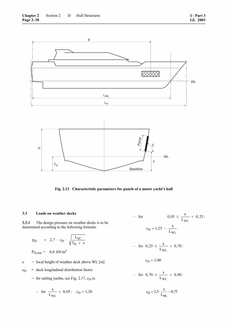
+,+
+-
-1
0�'� ���
-1
�
�
����
.-
-
2
Fig. 2.13 Characteristic parameters for panels of a motor yacht’s hull
3.3 Loads on weather decks
3.3.1 The design pressure on weather decks is to be determined according to the following formula:
SCD D
H
Lp 2,7 c
T z= ⋅ ⋅
+
PD,min = 6,0 kN/m2
z = local height of weather deck above WL [m]
cD = deck longitudinal distribution factor
= for sailing yachts, see Fig. 2.17, cD is:
– for WL
x 0,05 :L
< Dc 1,20=
– for WL
x0,05 0, 25 :L
≤ <
DWL
xc 1,25L
= −
– for WL
x0, 25 0,70 :L
≤ <
Dc 1,00=
– for WL
x0,70 0,90 :L
≤ <
DWL
xc 2,5 0,75L
= ⋅ −
Chapter 2 Page 2–38
Section 2 Hull Structures I - Part 3GL 2003
D
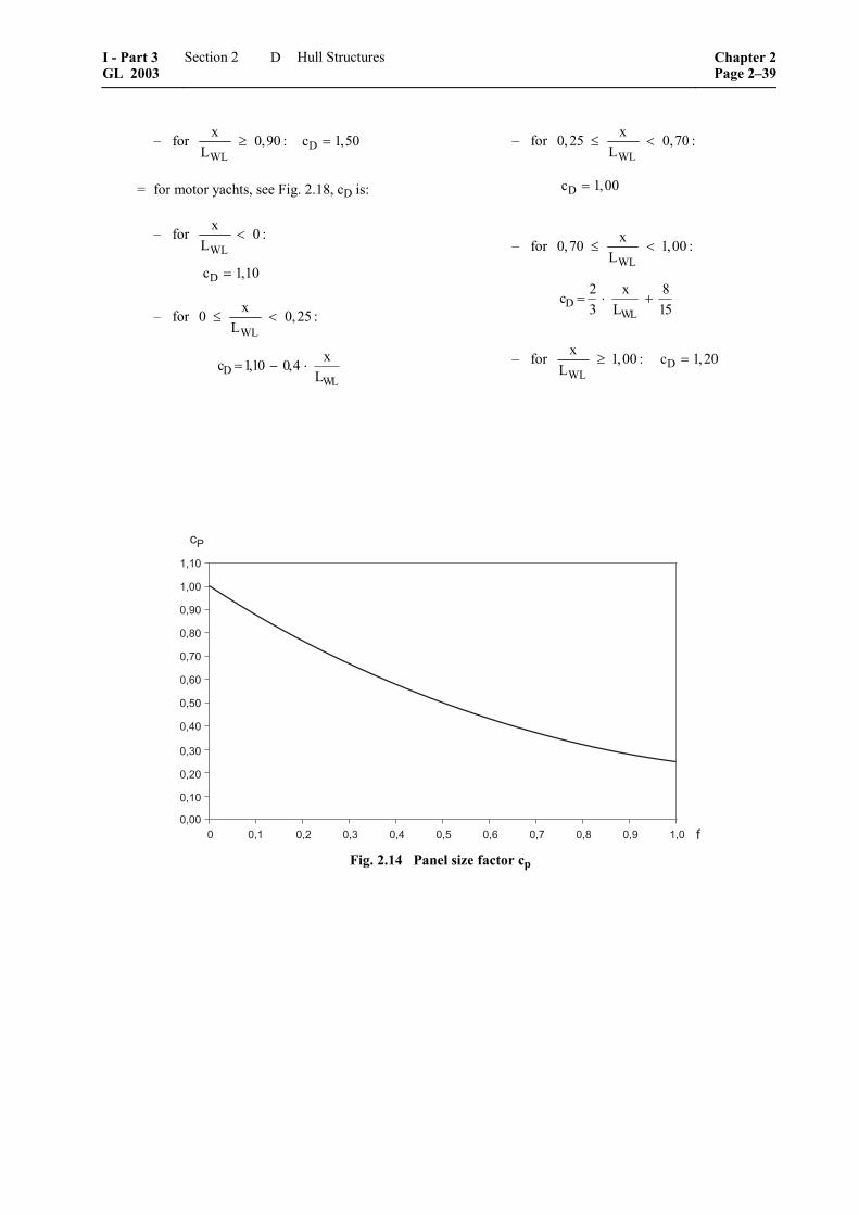
– for WL
x 0,90 :L
≥ Dc 1,50=
= for motor yachts, see Fig. 2.18, cD is:
– for WL
x 0 :L
<
Dc 1,10=
– for WL
x0 0,25 :L
≤ <
DWL
xc 1,10 0,4L
= − ⋅
– for WL
x0, 25 0,70 :L
≤ <
Dc 1,00=
– for WL
x0,70 1,00 :L
≤ <
DWL
2 x 8c3 L 15
= ⋅ +
– for WL
x 1,00 :L
≥ Dc 1,20=
����
����
��3�
��4�
��5�
��6�
����
����
����
���
����
����� ��� �� ��� ��� ��� ��6 ��5 ��4 ��3 ���
��
! Fig. 2.14 Panel size factor cp
I - Part 3 GL 2003
Section 2 Hull Structures Chapter 2Page 2–39
D

���
��
���
���
��3
��4
��5
��6
���
���
���
��7�� 7��� � ��� �� ��� ��� ��6 ��5 ��3 ���
�1
��1-1
���
��� ��4 ��� ��
1������8������ ������.��������%�*�'�!�����+��������4�+
9�����+:9����4�+:
���
��
���
���
��3
��4
��5
��6
���
���
���
��
���
Fig. 2.15 Hull longitudinal distribution factor for sailing yachts cL
���
��
���
���
��3
��4
��5
��6
���
���
���
��7�� 7��� � ��� �� ��� ��� ��6 ��5 ��3 ���
�1
��1-1
���
��� ��4 ��� ��
1������8������ ������.��������%�*�'�!�����+��������4�+
9�����+:9����4�+:
���
��
���
���
��3
��4
��5
��6
���
���
���
��
���
Fig. 2.16 Hull longitudinal distribution factor for motor yachts cL
Chapter 2 Page 2–40
Section 2 Hull Structures I - Part 3GL 2003
D

3.4 Loads on superstructures and deckhouses
3.4.1 Loads on walls
3.4.1.1 Front walls
The design load is:
2AFW Dp 1,5 p kN m⎡ ⎤= ⋅ ⎣ ⎦
3.4.1.2 Side walls
The design load is:
2ASW Dp 1,2 p kN m⎡ ⎤= ⋅ ⎣ ⎦
3.4.1.3 Aft walls
The design load is:
2AAW Dp 0,8 p kN m⎡ ⎤= ⋅ ⎣ ⎦
3.4.2 Loads on superstructure decks
The load on decks of superstructures and deckhouses is based on the load on the weather deck according to 3.3 and is defined by the following formula:
DA D 2
2DA,min
kNp p nm
p 4,0 kN m
⎡ ⎤= ⋅ ⎢ ⎥
⎣ ⎦
=
n = z110−
−H
z = vertical distance of the deck above the base line [m]
3.5 Loads on accommodation decks
The load on accommodation decks can be assumed as:
2L C Dp p c kN m⎡ ⎤= ⋅ ⎣ ⎦
pC = to be defined by the designer in connection with the owner's specification [kN/m2]
pCmin = 3,5 kN/m2
cD = deck longitudinal distribution factor accord-ing to Fig. 2.17 and 2.18
3.6 Loads on bulkheads
3.6.1 Collision bulkhead
The design load is:
2CBH BHp 11,5 z kN m⎡ ⎤= ⋅ ⎣ ⎦
zBH = vertical distance from the load centre to the top of the bulkhead [m]
3.6.2 Other bulkheads
The design load is:
2BH BHp 10,0 z kN m⎡ ⎤= ⋅ ⎣ ⎦
3.7 Loads on tank structures
The design load is:
2T Tp 10,0 z kN m⎡ ⎤= ⋅ ⎣ ⎦
zT = vertical distance from the load centre to the top of the tank overflow [m]
= not to be taken less than 2,0 m
4. Scantlings
4.1 General
For the scantlings of "high speed" motor yachts see 3.1.1.
4.1.1 Rounding-off tolerances
If the determined plate thickness differs from full or half mm they may be rounded off to full or half mm up to 0,2 mm or 0,7 mm; above 0,2 and 0,7 mm they are to be rounded up.
4.1.2 Corrosion allowances
The following, reduced corrosion allowances may be applied for yachts, if special care for maintenance and special attention for measures of corrosion protection can be assumed.
4.1.2.1 Steel
The scantlings require the following allowances tk to the theoretical, rounded-off plate thickness:
– tK = 0,5 mm in general
– tK = 0,7 mm for lubrication oil, gas oil or equivalent tanks
– tK = 1,0 mm for water ballast and heavy oil tanks
– for special applications tK shall be agreed with GL
For all elements of the yacht's structure which are forming a boundary of tanks, the tK values for tanks have to be considered.
I - Part 3 GL 2003
Section 2 Hull Structures Chapter 2Page 2–41
D
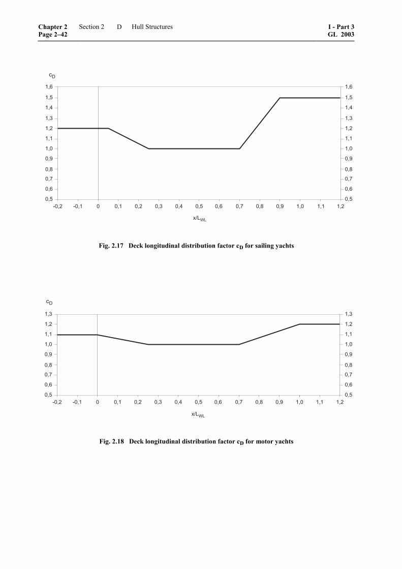
��6
���
���
���
��
���
���
���
��3
��4
��5
��6
� ��� �� ��� ��� ��� ��6 ��5 ��4 ��3 ���
�#
��1-1
��� ��7�� 7���
��6
���
���
���
��
���
���
���
��3
��4
��5
��6
Fig. 2.17 Deck longitudinal distribution factor cD for sailing yachts
���
��
���
���
���
��3
��4
��5
��6
� ��� �� ��� ��� ��� ��6 ��5 ��4 ��3 ���
�#
��1-1
7�� 7��� ��� ��
���
��
���
���
���
��3
��4
��5
��6
Fig. 2.18 Deck longitudinal distribution factor cD for motor yachts
Chapter 2 Page 2–42
Section 2 Hull Structures I - Part 3GL 2003
D
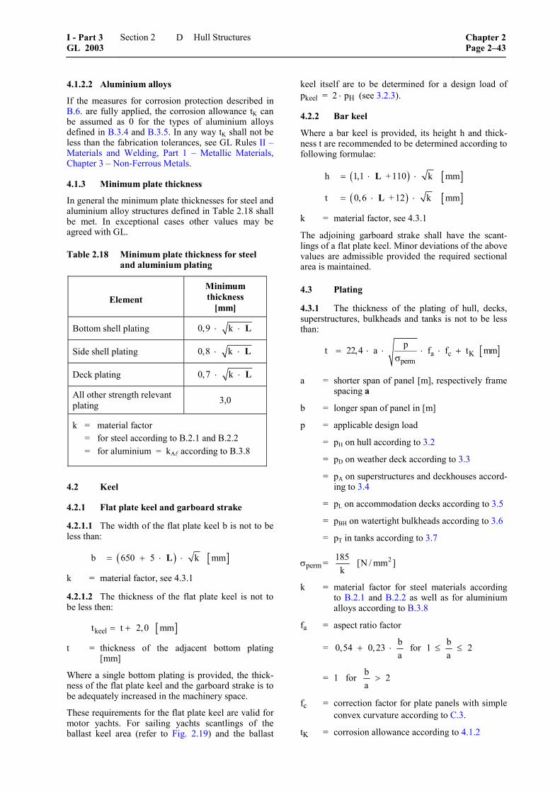
4.1.2.2 Aluminium alloys
If the measures for corrosion protection described in B.6. are fully applied, the corrosion allowance tK can be assumed as 0 for the types of aluminium alloys defined in B.3.4 and B.3.5. In any way tK shall not be less than the fabrication tolerances, see GL Rules II – Materials and Welding, Part 1 – Metallic Materials, Chapter 3 – Non-Ferrous Metals.
4.1.3 Minimum plate thickness
In general the minimum plate thicknesses for steel and aluminium alloy structures defined in Table 2.18 shall be met. In exceptional cases other values may be agreed with GL.
Table 2.18 Minimum plate thickness for steel and aluminium plating
Element Minimum thickness
[mm]
Bottom shell plating 0,9 k⋅ ⋅ L
Side shell plating 0,8 k⋅ ⋅ L
Deck plating 0,7 k⋅ ⋅ L
All other strength relevant plating 3,0
k = material factor = for steel according to B.2.1 and B.2.2 = for aluminium = kA according to B.3.8
4.2 Keel
4.2.1 Flat plate keel and garboard strake
4.2.1.1 The width of the flat plate keel b is not to be less than:
( ) [ ]b 650 5 k mm= + ⋅ ⋅L
k = material factor, see 4.3.1
4.2.1.2 The thickness of the flat plate keel is not to be less then:
[ ]keelt t 2,0 mm= +
t = thickness of the adjacent bottom plating [mm]
Where a single bottom plating is provided, the thick-ness of the flat plate keel and the garboard strake is to be adequately increased in the machinery space.
These requirements for the flat plate keel are valid for motor yachts. For sailing yachts scantlings of the ballast keel area (refer to Fig. 2.19) and the ballast
keel itself are to be determined for a design load of pkeel = 2 ⋅ pH (see 3.2.3).
4.2.2 Bar keel
Where a bar keel is provided, its height h and thick-ness t are recommended to be determined according to following formulae:
( ) [ ]h 1,1 + 110 k mm= ⋅ ⋅L
( ) [ ]t 0,6 + 12 k mm= ⋅ ⋅L
k = material factor, see 4.3.1
The adjoining garboard strake shall have the scant-lings of a flat plate keel. Minor deviations of the above values are admissible provided the required sectional area is maintained.
4.3 Plating
4.3.1 The thickness of the plating of hull, decks, superstructures, bulkheads and tanks is not to be less than:
[ ]a c Kperm
pt 22,4 a f f t mm= ⋅ ⋅ ⋅ ⋅ +σ
a = shorter span of panel [m], respectively frame spacing a
b = longer span of panel in [m]
p = applicable design load
= pH on hull according to 3.2
= pD on weather deck according to 3.3
= pA on superstructures and deckhouses accord-ing to 3.4
= pL on accommodation decks according to 3.5
= pBH on watertight bulkheads according to 3.6
= pT in tanks according to 3.7
σperm = 2185 [N / mm ]k
k = material factor for steel materials according to B.2.1 and B.2.2 as well as for aluminium alloys according to B.3.8
fa = aspect ratio factor
= b0,54 0,23a
+ ⋅ for b1 2a
≤ ≤
= 1 for b 2a
>
fc = correction factor for plate panels with simple convex curvature according to C.3.
tK = corrosion allowance according to 4.1.2
I - Part 3 GL 2003
Section 2 Hull Structures Chapter 2Page 2–43
D

4.3.2 Compliance with minimum thickness re-quirements according to 4.1.3 is always mandatory.
4.4 Structural members
4.4.1 General
The following formulae to determine the required section modulus and shear area apply to stiffeners, frames, floors, beams and girders. They are valid for stiffening members with webs either perpendicular to the plating or deviating not more than 15° from the perpendicular. In case this angle α exceeds 15°, the required values are obtained by dividing the results of the following formulae by cos α.
4.4.2 Section modulus
The section modulus W of a stiffening member re-quired for support of the plating loaded with the de-sign pressure is not to be less than:
2
3cs
perm
c p aW f [cm ]⋅ ⋅ ⋅= ⋅
σ
c = correction factor for boundary conditions = 83 for both ends constraint, see C.6. = 125 for one or both ends simply supported,
see C.6.
p = applicable design load [kN/m2] according to 3.
a = load span [m]
= unsupported length of stiffener [m], see C.5.
fcs = correction factor for plate panels with simple convex curvature according to C.4.
σperm = permissible stress
= 2150 [N / mm ]k
k = material factor for steel materials according to B.2.1 and B.2.2 as well as for aluminium alloys according to B.3.8
4.4.3 Shear area
The shear area, i.e. the cross sectional area of the web of the stiffening member A is not to be less than:
2
perm
5 p aA cm⋅ ⋅ ⋅ ⎡ ⎤= ⎣ ⎦τ
p, a, , k as defined in 4.4.2
τperm = permissible shear stress
= 2100 N mmk
⎡ ⎤⎣ ⎦
4.4.4 Brackets
Required scantlings for brackets are defined in C.6.3.
4.5 Permissible equivalent stress
4.5.1 The equivalent stress σv for hull structural members is to be determined according to:
2 2 2v b 3 N mm⎡ ⎤σ = σ + ⋅ τ ⎣ ⎦
σb = bending stress [N/mm2]
τ = shear stress [N/mm2]
4.5.2 The equivalent stress for steel structures is not to exceed the following value:
2v
190 N mmk
⎡ ⎤σ = ⎣ ⎦
k = material factor for steel according to B.2.1 and B.2.2
4.5.3 The equivalent stress for aluminium struc-tures is not to exceed the following value:
2v
A
190 [N / mm ]k
σ =
kA = material factor for aluminium according to B.3.8
4.6 Pillars
4.6.1 General
4.6.1.1 Structural members at heads and heels of pillars as well as substructures are to be constructed according to the forces they are subject to. Pillars shall rest on girders, floors or other pillars. Openings in webs of floors and girders below pillars are to be avoided. Where pillars on the inner bottom are not in way of intersections of floors and girders, partial floors or other structures are to be provided to support the load transmitted.
4.6.1.2 At the head and the heel of tubular pillars, plates are generally to be arranged. The connection is to be so dimensioned that at least 1 cm² cross sectional area is available for 10 kN of load.
4.6.1.3 Where possible, upper deck pillars shall be aligned with pillars below. Stiffeners ensuring effi-cient load distribution are to be fitted at the ends of pillars.
4.6.1.4 Pillars in tanks are to be checked for tension. Tubular pillars are not permitted in tanks for flamma-ble liquids.
4.6.2 Definition of loads and geometric parame-ters
PS = pillar load [kN]
= L ip A P⋅ +
Chapter 2 Page 2–44
Section 2 Hull Structures I - Part 3GL 2003
D
pL = load on decks [kN/m2] according to 3.3 to 3.5
A = load area for one pillar [m2]
Pi = load from pillars located above the pillar considered [kN]
S = length of the pillar [cm]
IS = 2S SA i⋅
= moment of inertia of the pillar [cm4] consid-ering effective width
AS = sectional area of the pillar [cm2]
iS = radius of gyration of the pillar [cm]
= 0,25 ⋅ dS for solid pillars of circular cross section
= 2 2a i0, 25 d d+
da = outside diameter of tubular pillars [cm]
di = inside diameter of pillar [cm]
dS = pillar diameter of solid pillars [cm]
4.6.3 Buckling criterion
The chosen scantlings of a pillar have to meet the following buckling criterion:
x
eH
1,11
R⋅ σ
≤κ ⋅
In case of aluminium alloy pillars ReH is to be substi-tuted by Rp0,2 (see B.3.8)
σx = buckling stress in longitudinal direction of the pillar [N/mm2]
Sx
S
P 10A
ν ⋅ ⋅σ =
ν = safety factor
= 1,50
κ = reduction factor
2 2
1κ =
φ + φ − λ
φ = ( )( )2p0,5 1 n 0,2+ λ − + λ
nP = 0,34 for pipes and box sections
= 0,49 for open sections
λ = eH
ki
Rσ
ReH = minimum nominal upper yield stress [N/mm2] according to B.2.1 and B.2.2
σki = pillar buckling stress [N/mm2]
= 2
S2 2s S S
E Ik A
π ⋅ ⋅
⋅ ⋅
E = modulus of elasticity [N/mm2]
kS = 1,0 in general. For pillars which end supports can be considered as rigidly fixed, kS may be reduced accordingly.
4.6.4 Minimum wall thickness
The wall thickness of tubular pillars which may be expected to be damaged during equipment handling, etc. is not to be less than:
[ ]w a
a
t 4,5 0,015 d mm
for d 300 mm
= +
≤
[ ]w a
a
t 0,03 d mm
for d 300 mm>
=
4.7 Foundations for main propulsion engines
4.7.1 General
4.7.1.1 The following requirements apply to diesel engines, gears and generators.
4.7.1.2 The rigidity of the engine seating and the surrounding bottom structure must be adequate to keep the deformations of the system due to the loads within the permissible limits. In special cases, proof of deformations and stresses may be required.
4.7.2 Due regard is to be paid, at the initial design stage, to a good transmission of forces in transverse and longitudinal direction.
4.7.3 The foundation bolts for fastening the engine at the seating shall be spaced no more than 3 × d apart from the longitudinal foundation girder. Where the distance of the foundation bolts from the longitudinal foundation girder is greater, proof of equivalence is to be provided.
d = diameter of the foundation bolts
4.7.4 In the whole speed range of main propulsion installations for continuous service resonance vibra-tions with inadmissible vibration amplitudes must not occur; if necessary structural variations have to be provided for avoiding resonance frequencies. Other-wise, a barred speed range has to be fixed. Within a range of – 10 % to + 5 % related to the rated speed no barred speed range is permitted. GL may require a vibration analysis and, if deemed necessary, vibration measurement.
I - Part 3 GL 2003
Section 2 Hull Structures Chapter 2Page 2–45
D

4.7.5 Longitudinal girders
4.7.5.1 The thickness of longitudinal girders for internal combustion engines is not to be less than:
[ ]1 m
P G 3,75t mmn e c 280
⎛ ⎞= +⎜ ⎟⋅ ⋅⎝ ⎠
c = 110,025 P
−⋅
0, 2 c 0,5≤ ≤ for 4-stroke engines
= 110,05 P
−⋅
0,3≥ for 2-stroke engines
tmin = [ ]p0, 4 t mm⋅
tp = thickness of top plate, see 4.7.5.3
P = rated driving power of the engine [kW]
n = rated speed at output [1/min]
G = weight of engine [kN]
m = bolted length of engine on foundation [m]
el = distance of the longitudinal girders [m]
The web thickness of longitudinal girders for elasti-cally mounted four-stroke internal combustion engines may be reduced to
t ' 0, 4 t= ⋅
if brackets are provided below the mountings, besides each bolt. The web thickness may be reduced to
t ' 0,9 t= ⋅
if two longitudinal girders are provided at each side of an internal combustion engine.
4.7.5.2 The thickness of the longitudinal girders for gears or generators is not to be less than:
[ ]1
1 m
Pt mmen e3
=⎛ ⎞⋅ +⎜ ⎟⎝ ⎠
P = rated output of gear or generator [kW]
el, m = see 4.7.5.1
4.7.5.3 The sizes of the top plate (width and thick-ness) shall be sufficient to attain efficient attachment and seating of the engine and – depending on seating height and type of engine – adequate transverse rigid-ity.
The thickness of the top plate shall be:
[ ]pt 0,9 d mm= ⋅
d = diameter of the foundation bolts [mm]
The cross sectional area of the top plate is not to be less than:
2T
PA 30 cm for P 750 kW15
⎡ ⎤= + ≤⎣ ⎦
2T
PA 70 cm for P 750 kW75
⎡ ⎤= + >⎣ ⎦
P = see 4.7.5.1
Where twin engines are fitted, a continuous top plate is to be arranged in general if the engines are coupled to one propeller shaft.
4.7.5.4 Top plates are preferably to be connected to longitudinal and transverse girders thicker than approx. 15 mm by means of a double bevel butt joint (K butt joint).
4.8 Transverse support of longitudinal girders
4.8.1 The sectional modulus and the cross sectional area of the floor plates between longitudinal girders are not to be less than:
31
m
120 P 7 aW e G cmn
⋅ ⋅⎛ ⎞ ⎡ ⎤= + ⋅⎜ ⎟ ⎣ ⎦⎝ ⎠
2S
m
0,35 a GA cm⋅ ⋅ ⎡ ⎤= ⎣ ⎦
a = distance of the floor plates [m]. For all other parameters see 4.7.5.1.
4.8.2 The longitudinal girders of the engine seating are to be supported transversely by means of web frames or wing bulkheads.
4.9 Foundations for deck machinery and mooring equipment
4.9.1 For deck machinery, like anchor windlasses, mooring winches, boat davits, etc. the most critical operational loads have to be considered for an analy-sis.
4.9.2 For windlasses and chain stoppers the acting forces on the foundation are to be calculated for 100 % of the rated breaking load of the chain cable. The resulting normal stress in the supporting structure shall not exceed the minimum nominal upper yield point ReH. Shear stress is to be within:
eHR3
Chapter 2 Page 2–46
Section 2 Hull Structures I - Part 3GL 2003
D

E. Motor and Sailing Yachts, 24 m ≤ L ≤ 48 m, Composite Structures
1. General
1.1 Scope
1.1.1 The following specifies requirements for design and construction of hulls for motor and sailing yachts with 24 m ≤ L ≤ 48 m, made from composite materials. The term composite refers to fibre rein-forced plastic (FRP) materials of the single skin type or to FRP skins in conjunction with lightweight core materials, i.e. sandwich types. For lengths L above 48 m special considerations for the extrapolation of these Rules have to be agreed with GL. The require-ments apply also to hulls of cold-moulded wood con-struction.
1.1.2 The following may be also used for craft other than yachts, like work boats, patrol boats, etc. For such craft an additional safety factor of 1,2 regard-ing permissible stresses shall be applied.
1.1.3 Different types of fibres and the multitude of fibre arrangements, as well as different core materials give rise to sophisticated laminate lay-ups of compo-nents specifically designed for the loads expected. Strength and stiffness calculations for such structures require careful analysis.
1.2 Materials
1.2.1 Regarding FRP and core materials, the GL Rules II – Materials and Welding, Part 2 – Non-metallic Materials, Chapter 1 – Fibre Reinforced Plas-tics and Adhesive Joints apply. An excerpt of these Rules is contained in B.7.
1.2.2 The actual mechanical properties of all FRP layers and the core materials have to be submitted to GL and are to be verified by tests. The information about the properties shall also include nominal thick-ness of each ply, specific weight per area and fibre content.
2. Design principles
2.1 General structural arrangement
2.1.1 The hull structural arrangement shall consist of an effective strengthening system of bulkheads, web frames, longitudinal girders, etc. as well as trans-verse and/or longitudinal frames or stiffeners. Longi-tudinal stiffeners are to be supported by transverse web frames or transverse bulkheads. Transverse frames are to be supported by longitudinal girders or other longitudinal structural members.
Where bulkheads, bunks, shelves, or other structurally effective interior components are laminated to the hull to provide structural support, they are generally to be bonded by laminate angles on both sides.
2.1.2 Care is to be taken to ensure structural conti-nuity and to avoid sharp corners and abrupt changes in section and shape.
Where frames, beams and stiffeners are intercostal at an intersecting member, the connections are to provide continuity of strength.
2.1.3 Floors are to be fitted in line with transverse webs or transverse frames. Alternatively, floors may terminate at longitudinal girders which in turn are supported by deep web rings or transverse bulkheads. Floors or equivalent stiffeners are to be fitted in the area of the engine foundations, the rudder skeg and the propeller bracket, if applicable. For sailing yachts with short ballast keels, a reinforced floor at the leading and trailing edge of the keel is to be arranged.
2.1.4 Sailing craft shall have transverse bulkheads or equivalent structures in way of mast(s) in order to achieve adequate transverse rigidity. Transverse bulk-heads or deep brackets are to be provided in way of chainplates.
2.2 Longitudinal strength
Under certain conditions after consultation with GL a check of longitudinal strength is to be carried out.
2.3 Bulkheads
2.3.1 Number and location of watertight bulkheads should be considered in the early design phase to ensure compliance with these Rules and possibly other relevant regulations.
Bulkhead stiffeners, where required, are to be aligned with hull girders. Where vertical stiffeners are cut in way of watertight doors, reinforced stiffeners are to be fitted on each side of the door opening and crossbars are to be provided to support the cut-off stiffeners.
2.3.2 Collision bulkhead
The collision bulkhead shall extend up to the free-board deck. Steps or recesses may be permitted.
Openings in the collision bulkhead shall be watertight and permanently closed in sailing condition. Closing appliances and their number shall be reduced to the minimum, compatible with the design and proper working of the yacht.
Where pipes are penetrating the collision bulkhead, screwdown valves are to be fitted directly at the colli-sion bulkhead. Such valves are to be operable from outside the forepeak.
2.3.3 Stern tube bulkhead
All yachts are to have a stern tube bulkhead which is, in general, to be so arranged that the stern tube and rudder trunk are enclosed in a watertight compart-ment. The stern tube bulkhead shall extend to the freeboard deck or to a watertight platform situated above the load waterline.
I - Part 3 GL 2003
Section 2 Hull Structures Chapter 2Page 2–47
E
Where a complete stern tube bulkhead is not practica-ble, only watertight void spaces enclosing the stern tube entrance, providing the possibility for a second watertight sealing may be provided after agreement with GL. The same arrangement can be applied for the rudder trunk.
2.3.4 Remaining watertight bulkheads
Remaining watertight bulkheads are, depending on the type of yacht and the Classification for damage stabil-ity, to extend to the freeboard deck. Wherever practi-cable, they shall be situated in one frame plane, oth-erwise those portions of decks situated between parts of transverse bulkheads are to be watertight.
It is recommended that bulkheads shall be fitted sepa-rating the machinery space from service spaces and accommodation rooms forward and aft and made watertight and gastight up to the freeboard deck.
2.3.5 Openings in watertight bulkheads
2.3.5.1 Type and arrangement of doors are to be submitted for approval.
In watertight bulkheads other than collision bulkheads, watertight doors may be fitted. Below the deepest load waterline, they are to be constructed as sliding doors, exemptions may be granted on case by case. Above that waterline, hinged doors may be approved.
Watertight doors are to be sufficiently strong and of an approved design.
Openings for watertight doors in the bulkheads are to be effectively framed such as to facilitate proper fit-ting of the doors and to guarantee watertightness.
2.3.5.2 Watertight bulkhead doors and their frames are to be tested before they are fitted onboard by a head of water corresponding to the freeboard deck height or the results from damage stability calculation. Alternatively, watertight doors may be used which have been type approved in accordance with GL spe-cial acceptance procedure. After having been fitted on board, the doors are to be soap-tested for tightness and to be subject to an operational test.
2.3.5.3 Penetrations through watertight bulkheads
Where bulkhead fittings are penetrating watertight bulkheads, care is to be taken to maintain watertight-ness. For penetrations through the collision bulkhead 2.3.2 is to be observed.
2.4 Openings
Corners of all openings in strength structures are to be well rounded. If necessary, the shape of openings is to be so designed as to reduce stress concentrations. Structural integrity must be maintained around open-ings. In highly stressed areas openings should be avoided as far as possible.
2.5 Bottom structure
2.5.1 In general, continuous longitudinal girders are to be provided and shall extend as far aft and for-ward as practicable. A centreline girder is to be fitted for docking purposes unless sufficient strength and stiffness is already achieved by the external keel or the bottom shape.
2.5.2 Size and location of cut-outs in floors and girders must be appropriately designed for the occur-ring loads. Particularly at the ends of floors and gird-ers sufficient shear area is required.
2.5.3 A floor or a girder is to be provided under each line of pillars.
2.5.4 In case of a double bottom, manholes must be arranged for access to all parts of the double bottom.
2.5.5 Where solid ballast is fitted, it is to be se-curely positioned. If necessary, intermediate floors may be fitted for this purpose.
If a ballast keel is fitted, the bottom structure is to be reinforced due to additional loads transmitted by the keel. Special care is to be taken with the structural support of fin keel’s leading and trailing edge.
2.6 Engine foundation
Longitudinal girders forming the engine seatings must extend fore and aft as far as possible and are to be suitably supported by floors, transverse frames and/or brackets. In way of thrust bearing additional strength-ening is to be provided.
2.7 Side structure and bulwarks
2.7.1 Longitudinal stiffeners, if fitted, shall be continuous as far as possible.
2.7.2 Bulwark plating is to be determined by apply-ing the side design pressure for the relevant vertical height. Bulwark stanchions must be in line with trans-verse beams, or adequate substructure must be pro-vided by other means.
2.8 Tank structures
2.8.1 Fore peak tanks shall not be used for carrying fuel oil.
2.8.2 Fresh water tanks are to be separated from other tanks such as waste water tanks by cofferdams. The same applies to fuel tanks. Generally, also tanks such as lubricating or hydraulic oil tanks shall be separated from each other by equivalent means.
2.8.3 Each tank is to be fitted with air pipes, over-flow and sounding pipes, see Section 1, C.7.11.
Chapter 2 Page 2–48
Section 2 Hull Structures I - Part 3GL 2003
E

2.9 Deck
2.9.1 In case of longitudinal deck stiffeners, deck beams are to be located in way of the vertical web frames of the side shell. Structural continuity of the stiffeners is to be ensured.
2.9.2 In case of transverse deck stiffeners, deck beams are to be, in general, fitted at every frame, in line with side shell stiffeners.
2.10 Superstructures and deckhouses
2.10.1 Superstructure and deckhouse front and aft bulkheads are to be aligned with bulkheads, web frames or pillars in the hull or in the superstructure or deckhouse below.
2.10.2 Web frames or partial/wing bulkheads are to be provided to ensure transverse rigidity in large deckhouses. The strength members are to be suitably reinforced in the area of masts and other load concen-trations.
2.10.3 Ends of superstructures and deckhouses are to be efficiently supported by bulkheads, pillars or other equivalent arrangements
2.10.4 As a rule, the spacing of stiffeners on sides of superstructures and deckhouses is to be the same as those of beams on supporting decks
2.10.5 Structural discontinuities and rigid points are to be avoided. Where structural elements are weak-ened, e.g. by openings, proper compensation is to be provided.
2.11 Constructional details
2.11.1 Cut-outs for the passage of ordinary stiffeners through primary stiffeners, like girders, etc. are to be as small as possible. As a rule, the depth of cut-outs is not to be greater than half the web height of the pri-mary stiffener.
2.11.2 Changes of thickness for a single-skin lami-nate are to be made as gradually as possible and over a width which is, in general, not to be less than thirty times the difference in thickness.
The connection between a single-skin laminate and a sandwich laminate is to be carried out as gradually as possible over a width which is, in general, not to be less than three times the thickness of the sandwich core.
2.11.3 Laminate edges and holes are to be sealed.
2.11.4 In way of bolted connections and fittings, the sandwich core is to be replaced by inserts of high density foam or single-skin laminate.
3. Design loads
3.1 General
3.1.1 For "high speed" motor yachts which are capable of speeds
[ ]6v 7,2 kn≥ ⋅ ∇
where
∇ = moulded volume [m3] according to A.6.6
the relevant design loads of the GL Rules Part 1 – Seagoing Ships, Chapter 5 – High Speed Craft, see Annex A apply in combination with the scantling requirements of 4.
3.1.2 The design loads for sailing and motor yachts not considered as of the "high speed" type are speci-fied in the following. The design loads are to be ap-plied at the following load points:
– for panels: lower edge of panel
– for structural members: centre of the area sup-ported by the element
3.1.3 Definition of symbols
LSC = scantling length [m]
= H WLL L2
+
LH = length of the yacht's hull measured parallel to the design waterline [m], see Fig. 2.19
LWL = length of the yacht from the foreside of the stem to the after side of the stern or transom, measured at the design waterline [m], see Fig. 2.19
TH = see A.6.2.10
3.2 Loads on hull
3.2.1 The load pH [kN/m2] on the yacht's hull is to be determined as follows:
H H RY p L
0SC
SC
zp 10 T 1 c c cH
vL 1 cos
1,53 L
⎛ ⎞= ⋅ − + ⋅ ⋅⎜ ⎟⎝ ⎠
⎛ ⎞ ⎛ α ⎞⎜ ⎟⋅ + ⋅ ⎜ ⎟⎜ ⎟⋅ ⎝ ⎠⎝ ⎠
cp = panel size factor as a function of f, see also Fig. 2.20
= 20,54 f 1, 29 f 1⋅ − ⋅ +
I - Part 3 GL 2003
Section 2 Hull Structures Chapter 2Page 2–49
E
f = SC
a 25055 L 550
−⋅ +
a = panel's short span respectively load span of stiffener [mm], not to be taken > 1 300 mm
cL = hull longitudinal distribution factor
= for sailing yachts, see Fig. 2.21, cL is:
– for WL
x 0 :L
<
Lc 0,80 for 24 m= =L
Lc 0,60 for 48 m= =L
– for WL
x0 0,65 :L
≤ <
LWL
xc 0,80 0,615 for 24 mL
= + ⋅ =L
LWL
xc 0,60 0,538 for 48 mL
= + ⋅ =L
– for WL
x 0,65 :L
≥
Lc 1,20 for 24 m= =L
Lc 0,95 for 48 m= =L
= for motor yachts, see Fig. 2.22, cL is:
– for WL
x 0 :L
<
Lc 0,85 for 24 m= =L
Lc 0,65 for 48 m= =L
– for WL
x0 0,5 :L
≤ <
LWL
xc 0,85 0,8 for 24 mL
= + ⋅ =L
LWL
xc 0,65 0,7 for 48 mL
= + ⋅ =L
– for WL
x 0,5 :L
≥
Lc 1,25 for 24 m= =L
Lc 1,00 for 48 m= =L
z = vertical distance between the load point and the moulded base line [m], see Fig. 2.19
α = β – 20° for sailing yachts (not smaller than 0°)
= β – 5° for motor yachts (not smaller than 0°)
β = deadrise angle at the load point, see Fig. 2.19
cRY = factor considering range of service, see Section 1, A.7.
= 1,0 for unrestricted service
= 0,95 for M, restricted international service
= 0,90 for K, coastal service
= 0,85 for W, sheltered water service
3.2.2 In any case the load pH shall not be smaller than: – 2
H minp 10 [kN / m ]= ⋅ H for the area of the hull below the full displace-
ment waterline
– 2H minp 5 [kN / m ]= ⋅ H
for the area of the hull above the full displace-ment waterline
3.2.3 The design load for the ballast keel area of sailing yachts as indicated in Fig. 2.19 shall be taken as:
keel Hp 2 p= ⋅
3.3 Loads on weather decks
3.3.1 The design pressure on weather decks is to be determined according to the following formula:
SCD D
H
Lp 2,7 c
T z= ⋅ ⋅
+
PD,min = 6,0 kN/m2
z = local height of weather deck above WL [m]
cD = deck longitudinal distribution factor
= for sailing yachts, see Fig. 2.23, cD is:
– for WL
x 0,05 :L
< Dc 1,20=
– for WL
x0,05 0, 25 :L
≤ <
DWL
xc 1,25L
= −
– for WL
x0, 25 0,70 :L
≤ <
Dc 1,00=
Chapter 2 Page 2–50
Section 2 Hull Structures I - Part 3GL 2003
E
– for WL
x0,70 0,90 :L
≤ <
DWL
xc 2,5 0,75L
= ⋅ −
– for WL
x 0,90 :L
≥ Dc 1,50=
= for motor yachts, see Fig. 2.24, cD is:
– for WL
x 0 :L
< Dc 1,10=
– for WL
x0 0,25 :L
≤ <
DWL
xc 1,10 0,4L
= − ⋅
– for WL
x0, 25 0,70 :L
≤ <
Dc 1,00=
– for WL
x0,70 1,00 :L
≤ <
DWL
2 x 8c3 L 15
= ⋅ +
– for WL
x 1,00 :L
≥ Dc 1,20=
3.4 Loads on superstructures and deckhouses
3.4.1 Load on walls
3.4.1.1 Front walls
The design load is:
2AFW Dp 1,5 p [kN / m ]= ⋅
3.4.1.2 Side walls
The design load is:
2ASW Dp 1,2 p [kN / m ]= ⋅
3.4.1.3 Aft walls
The design load is:
2AAW Dp 0,8 p [kN / m ]= ⋅
3.4.2 Loads on superstructure decks
The load on decks of superstructures and deckhouses is based on the load on the weather deck according to 3.3 and is defined by the following formula:
2
DA D
2DA,min
p p n [kN / m ]
p 4,0 kN / m
= ⋅
=
n = z110−
−H
z = vertical distance of the deck above the base line [m]
3.5 Loads on accommodation decks
The load on accommodation decks can be assumed as:
2L C Dp p c [kN / m ]= ⋅
pC = to be defined by the designer in connection with the owner's specification [kN/m2]
pCmin = 3,5 kN/m2
cD = longitudinal distribution factor according to Fig. 2.23 and 2.24
3.6 Loads on bulkheads
3.6.1 Collision bulkhead
The design load is:
2BH BHp 11,5 z [kN / m ]= ⋅
zBH = vertical distance from the load centre to the top of the bulkhead in [m]
3.6.2 Other bulkheads
The design load is:
2BH BHp 10,0 z [kN / m ]= ⋅
I - Part 3 GL 2003
Section 2 Hull Structures Chapter 2Page 2–51
E
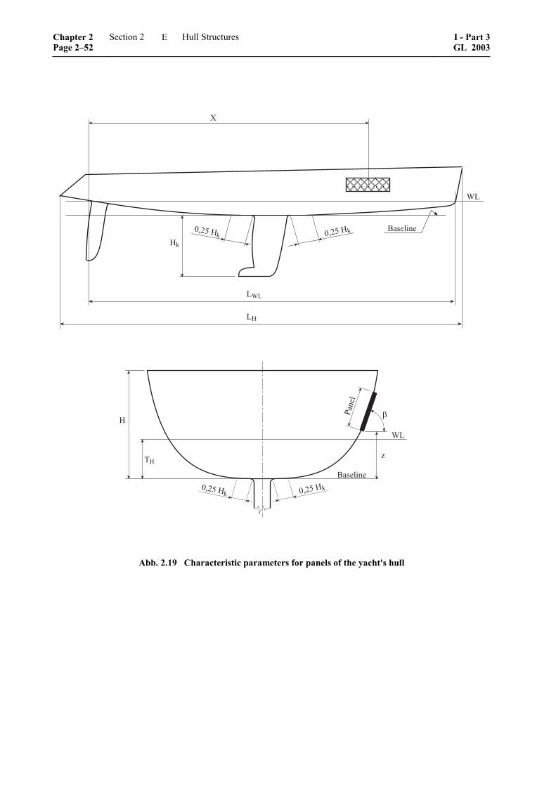
!1
<;
=*+')(,'
;<;
;!
>
�����!1 �����!1
<;
�
?
=*+')(,'
@*,')
!
!
�����!1 �����!1
Abb. 2.19 Characteristic parameters for panels of the yacht's hull
Chapter 2 Page 2–52
Section 2 Hull Structures I - Part 3GL 2003
E
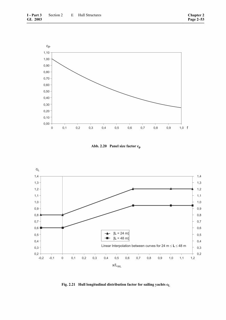
����
����
��3�
��4�
��5�
��6�
����
����
����
���
����
����� ��� �� ��� ��� ��� ��6 ��5 ��4 ��3 ���
��
!
Abb. 2.20 Panel size factor cp
���
��
���
���
��3
��4
��5
��6
���
���
���
��7�� 7��� � ��� �� ��� ��� ��6 ��5 ��3 ���
�1
��1-1
���
��� ��4 ��� ��
1������8������ ������.��������%�*�'�!�����+��������4�+
9�����+:9����4�+:
���
��
���
���
��3
��4
��5
��6
���
���
���
��
���
Fig. 2.21 Hull longitudinal distribution factor for sailing yachts cL
I - Part 3 GL 2003
Section 2 Hull Structures Chapter 2Page 2–53
E

���
���
���
���
��
���
���
���
���
���
���
������� ���� � ��� ��� ��� ��� ��� ��� �� ���
�;
�3;<;
���
��� ��� ��� ���
;(,'*��A,�'�$�)*�(�,��'�0'',��&�:'+��������.����������.
7�������.97�������.9
���
���
���
���
��
���
���
���
���
���
���
���
���
Fig. 2.22 Hull longitudinal distribution factor for motor yachts cL
��6
���
���
���
��
���
���
���
��3
��4
��5
��6
� ��� �� ��� ��� ��� ��6 ��5 ��4 ��3 ���
�#
��1-1
��� ��7�� 7���
��6
���
���
���
��
���
���
���
��3
��4
��5
��6
Abb. 2.23 Deck longitudinal distribution factor for sailing yachts cD
Chapter 2 Page 2–54
Section 2 Hull Structures I - Part 3GL 2003
E
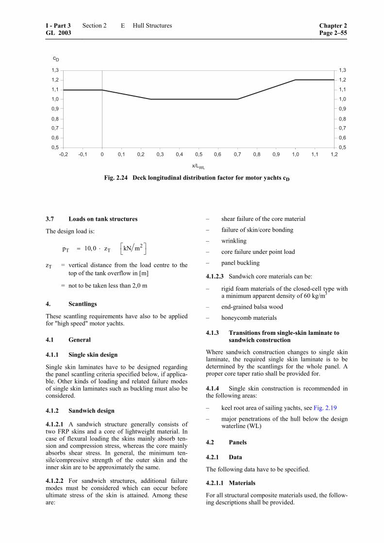
���
��
���
���
���
��3
��4
��5
��6
� ��� �� ��� ��� ��� ��6 ��5 ��4 ��3 ���
�#
��1-1
7�� 7��� ��� ��
���
��
���
���
���
��3
��4
��5
��6
Fig. 2.24 Deck longitudinal distribution factor for motor yachts cD
3.7 Loads on tank structures
The design load is:
2T Tp 10,0 z kN m⎡ ⎤= ⋅ ⎣ ⎦
zT = vertical distance from the load centre to the top of the tank overflow in [m]
= not to be taken less than 2,0 m
4. Scantlings
These scantling requirements have also to be applied for "high speed" motor yachts.
4.1 General
4.1.1 Single skin design
Single skin laminates have to be designed regarding the panel scantling criteria specified below, if applica-ble. Other kinds of loading and related failure modes of single skin laminates such as buckling must also be considered.
4.1.2 Sandwich design
4.1.2.1 A sandwich structure generally consists of two FRP skins and a core of lightweight material. In case of flexural loading the skins mainly absorb ten-sion and compression stress, whereas the core mainly absorbs shear stress. In general, the minimum ten-sile/compressive strength of the outer skin and the inner skin are to be approximately the same.
4.1.2.2 For sandwich structures, additional failure modes must be considered which can occur before ultimate stress of the skin is attained. Among these are:
– shear failure of the core material
– failure of skin/core bonding
– wrinkling
– core failure under point load
– panel buckling
4.1.2.3 Sandwich core materials can be:
– rigid foam materials of the closed-cell type with a minimum apparent density of 60 kg/m3
– end-grained balsa wood
– honeycomb materials
4.1.3 Transitions from single-skin laminate to sandwich construction
Where sandwich construction changes to single skin laminate, the required single skin laminate is to be determined by the scantlings for the whole panel. A proper core taper ratio shall be provided for.
4.1.4 Single skin construction is recommended in the following areas:
– keel root area of sailing yachts, see Fig. 2.19
– major penetrations of the hull below the design waterline (WL)
4.2 Panels
4.2.1 Data
The following data have to be specified.
4.2.1.1 Materials
For all structural composite materials used, the follow-ing descriptions shall be provided.
I - Part 3 GL 2003
Section 2 Hull Structures Chapter 2Page 2–55
E
Fibre and resin materials:
– resin system, specific gravity
Cured ply properties for:
– fibre areal weight – fibre orientation – consolidation method and fibre volume fraction – thickness – defined direction of mechanical properties – longitudinal and transverse stiffness, in-plane
shear stiffness 1 – longitudinal, transverse ultimate tensile and
compressive strength, in-plane ultimate shear strength 1
Core materials:
– type, manufacturer – nominal density – thickness – ultimate shear strength – compressive stiffness – shear stiffness
4.2.1.2 Laminates
For each structural component, the documentation must contain data covering: – laminate layup including listing of individual
layers and their orientation vs. defined coordi-nate system
– geometrical data about location, longitudinal and transverse span of panel
– curvature of panel
4.2.2 Applicable design load
Design loads as defined in 3. have to be applied.
4.2.3 Calculation method
The calculation shall be based on classic beam/plate and laminate theory.
4.2.4 Design criteria
The following requirements are to be met:
– a safety factor SF ≥ 4,0 relative to ultimate stress for each FRP layer
– a safety factor SF ≥ 2,5 relative to ultimate shear stress for the sandwich core
–––––––––––––– 1 In plane shear properties are relevant for layers containing a
high percentage of off-axis fibres.
– 1,5 % permissible panel deflection relative to the short span for single skin laminate
– 1,0 % permissible panel deflection relative to the short span for sandwich construction
4.3 Stiffeners and girders
4.3.1 Data
The following data have to be specified.
4.3.1.1 Materials
For all structural composite materials used, the follow-ing descriptions shall be provided.
Fibre and resin materials:
– resin system, specific gravity
Cured ply properties for:
– fibre areal weight
– fibre orientation
– consolidation method and fibre volume fraction
– thickness
– defined direction of mechanical properties
– longitudinal and transverse stiffness, in-plane shear stiffness 1
– longitudinal, transverse ultimate tensile and compressive strength, in-plane ultimate shear strength 1
Core materials:
– type, manufacturer
– nominal density
– compressive stress
4.3.1.2 Laminates
For each structural component the documentation must contain data covering:
– laminate layup including listing of individual layers and their orientation vs. defined coordi-nate system
– geometrical data about location, span of sup-ported panel, unsupported span of girder/stiff-ener
– data about section geometry of stiffener/girder
– bonding details
– curvature of panel
Chapter 2 Page 2–56
Section 2 Hull Structures I - Part 3GL 2003
E
4.3.2 Applicable design load
Design loads as defined in 3. have to be applied.
4.3.3 Calculation method
The calculation shall be based on classic beam/plate and laminate theory.
4.3.4 Design criteria
The following requirements have to be met:
– a safety factor SF ≥ 4,0 relative to ultimate stress for bending of each FRP layer
– a safety factor SF ≥ 4,0 relative to ultimate shear stress in stiffener webs
– 0,5 % permissible stiffener deflection relative to the unsupported span of the stiffener
– 0,3 % permissible stiffener deflection relative to the unsupported span of engine foun-dations
F. Motor und Sailing Yachts, 24 m ≤ L ≤ 48 m, Wooden Structures
1. General
1.1 Scope
The following references to rules and requirements applicable for traditionally built wooden hull struc-tures of motor and sailing yachts.
Yacht hulls of cold moulded wood are to be built according to the requirements of E.
1.2 Materials
An excerpt regarding material requirements is given in B.9. Furthermore reference is made to the GL Rules II – Materials and Welding, Part 2 – Non-metallic Mate-rials, Chapter 2 – Wooden Materials.
2. Scantlings
The actual determination of scantlings can be carried out according to the GL Rules for Classification and Construction:
I – Schiffstechnik, Teil 1 – Seeschiffe, Kapitel 13 – Vorschriften für Klassifikation und Bau von hölzernen Seeschiffen 2
Regarding anchor equipment and rudder and manoeu-vring arrangement the requirements of J. and K. apply.
–––––––––––––– 2 Translation: "Rules for Classification and Construction of
Wooden Seagoing Ships" (not available in English).
G. Motor and Sailing Yachts, L > 48 m, Steel and Aluminium Structures
1. General
1.1 Scope
The following references to GL Rules applicable for scantling determination of the hull structures of sailing and motor yachts with L > 48 m, see 2.
Regarding corrosion allowances and minimum thick-ness of plating the requirements specified in 2.2.2 and 2.2.3 are applicable.
1.2 Materials
See B.
2. Scantlings
2.1 Scantlings for high speed yachts
If a yacht is capable of a maximum speed equal to or exceeding
[ ]6v 7,2 kn= ⋅ ∇
∇ = moulded volume [m3] according to A.6.6
Chapter 1 – High Speed Craft, Section 3 will be ap-plied.
2.2 Scantlings for moderate speed yachts
2.2.1 For determination of the scantlings of yachts with lower speeds than defined in 2.1. The GL Rules Part 1 – Seagoing Ships, Chapter 1 – Hull Structures have to be applied. The deviations defined in 2.2.2 and 2.2.3 have to be observed.
Upon request further deviations of the scantlings may be granted by GL after detailed judgement of the ac-tual project.
2.2.2 Corrosion allowances
The following, reduced corrosion allowances may be applied for yachts, if special care for maintenance and special attention for measures of corrosion protection can be assumed.
2.2.2.1 Steel
The scantlings require the following allowances tk to the theoretical, rounded-off plate thickness:
– tK = 0,5 mm in general
– tK = 0,7 mm for lubrication oil, gas oil or equivalent tanks
– tK = 1,0 mm for water ballast and heavy oil tanks
I - Part 3 GL 2003
Section 2 Hull Structures Chapter 2Page 2–57
G
– for special applications tK shall be agreed with GL
For all elements of the yacht's structure which form a boundary of tanks, the tK values for tanks have to be considered.
2.2.2.2 Aluminium alloys
If the measures for corrosion protection described in B.6. are fully applied, the corrosion allowance tK can be assumed as 0 for the types of aluminium alloys defined in B.3.4 and B.3.5. In any way tK shall not be less than the fabrication tolerances, see GL Rules II –Materials and Welding, Part 1 – Metallic Materials, Chapter 3 – Non-Ferrous Metals, Section 1 – Alumin-ium Alloys.
2.2.3 Minimum thickness
The minimum thickness requirements of the plating of different elements of the hull structure are summarized in Table 2.19. For comparison the table indicates references to the GL Rules Part 1 – Seagoing Ships, Chapter 1 – Hull Structures.
H. Tank Structures
1. General
1.1 Subdivision of tanks
1.1.1 In tanks which extend over the full breadth of the yacht and are intended to be used for partial filling (e.g. fuel oil and fresh water tanks), at least one longi-tudinal bulkhead is to be fitted, which may be a swash bulkhead.
1.1.2 Where the forepeak is intended to be used as tank, at least one complete or partial longitudinal swash bulkhead is to be fitted, if the tank breadth exceeds 0,5 B or 6 m, whichever is the greater.
When the after peak is intended to be used as tank, at least one complete or partial longitudinal swash bulk-head is to be fitted. The largest breadth of the liquid surface should not exceed 0,3 B in the aft peak.
1.1.3 Peak tanks exceeding 0,06 L or 6 m in length, whichever is greater, shall be provided with a trans-verse swash bulkhead.
1.2 Air, overflow and sounding pipes
1.2.1 Each tank is to be fitted with air pipes, over-flow pipes and sounding pipes. The air pipes are to be led to above the exposed deck. The arrangement is to be such as to allow complete filling of the tanks. The height from the deck to the point where seawater may have access is to be at least 760 mm on the freeboard deck and 450 mm on a superstructure deck.
1.2.2 Suitable closing appliances are to be provided for air pipes, overflow pipes and sounding pipes, see also Section 1, C.7.11.
1.2.3 Closely below the inner bottom or the tank top, holes are to be cut into floor plates and side gird-ers as well as into beams, girders, etc., to give the air free access to the air pipes. Besides, all floor plates and side girders are to be provided with limbers to permit the water or oil to reach the pump suctions.
1.2.4 Sounding pipes are to be led to the bottom of the tank. The shell plating is to be strengthened by thicker plates or doubling plates under the sounding pipes.
1.3 Forepeak tank
Oil is not to be carried in a forepeak tank, see also D.2.9.1.
1.4 Cross references
1.4.1 Where a tank bulkhead forms part of a water-tight bulkhead, its strength is not to be less than re-quired by C. to G. as applicable.
1.4.2 For pumping and piping and fuel oil tanks see Section 1, C.7. For tanks in the double bottom see C. to G. as applicable.
1.4.3 For testing of tanks, see 4.
1.4.4 Where tanks are provided with cross flooding arrangements the increase of the pressure head is to be taken into consideration.
1.5 Separation of fuel oil tanks from tanks for other liquids
1.5.1 Fuel oil tanks are to be separated from tanks for other liquids by cofferdams. Generally, also tanks such as lubricating or hydraulic oil tanks shall be separated from each other by equivalent means.
Chapter 2 Page 2–58
Section 2 Hull Structures I - Part 3GL 2003
H
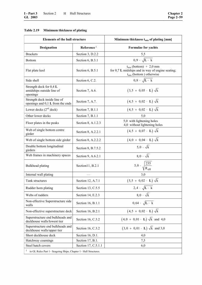
Table 2.19 Minimum thickness of plating
Elements of the hull structure Minimum thickness tmin of plating [mm]
Designation Reference 1 Formulae for yachts
Brackets Section 3, D.2.2 5,5
Bottom Section 6, B.3.1 0,9 k⋅ ⋅L
Flat plate keel Section 6, B.5.1 tmin (bottom) + 2,0 mm
for 0,7 L midships and in way of engine seating; tmin (bottom ) otherwise
Side shell Section 6, C.2. 0,8 k⋅ ⋅L
Strength deck for 0,4 L amidships outside line of openings
Section 7, A.6. ( )3,5 0,05 k+ ⋅ L
Strength deck inside line of openings and 0,1 L from the ends Section 7, A.7. ( )4,5 0,02 k+ ⋅ L
Lower decks (2nd deck) Section 7, B.1.1 ( )4,5 0,02 k+ ⋅ L
Other lower decks Section 7, B.1.1 5,0
Floor plates in the peaks Section 8, A.1.2.3 5,0 with lightening holes 4,0 without lightening holes
Web of single bottom centre girder Section 8, A.2.2.1 ( )4,5 0,07 k+ ⋅ L
Web of single bottom side girder Section 8, A.2.2.2 ( )4,0 0,04 k+ ⋅ L
Double bottom longitudinal girders Section 8, B.7.5.2 5,0 k⋅
Web frames in machinery spaces Section 9, A.6.2.1 8,0 k⋅
Bulkhead plating Section11, B.2.1 eH
2355,0R
⋅
Internal wall plating –– 3,0
Tank structures Section 12, A.7.1 ( )5,5 0,02 k+ ⋅ L
Rudder horn plating Section 13, C.5.5 2,4 k⋅ ⋅L
Webs of rudders Section 14, E.2.3 8,0 k⋅
Non-effective Superstructure side walls Section 16, B.1.1 0,64 k⋅ ⋅L
Non-effective superstructure deck Section 16, B.2.1 ( )4,5 0,02 k+ ⋅ L
Superstructure end bulkheads and deckhouse walls/lowest tier Section 16, C.3.2 ( )4,0 0,01 k+ ⋅ L and 4,0
Superstructure end bulkheads and deckhouse walls/upper tier Section 16, C.3.2 ( )3,0 0,01 k+ ⋅ L and 3,0
Short deckhouse deck Section 16, D.1. 4,0 Hatchway coamings Section 17, B.1. 7,5 Steel hatch covers Section 17, C.5.1.1 6,0 1 in GL Rules Part 1– Seagoing Ships, Chapter 1– Hull Structures.
I - Part 3 GL 2003
Section 2 Hull Structures Chapter 2Page 2–59
H

1.5.2 Upon special approval, the arrangement of cofferdams between fuel oil and lubricating oil tanks may be dispensed with on relatively small yachts, provided that:
– the common boundary is continuous, i.e. it does not abut at the adjacent tank boundaries, see Fig. 2.25
Where the common boundary cannot be con-structed continuously according to Fig. 2.25, the fillet welds on both sides of the common bound-ary are to be welded in two layers and the throat thickness is not to be less than 0,5 × t (t = plate thickness)
��������!�����
Fig. 2.25 Welding at non-continuous tank boundaries
– stiffeners or pipes do not penetrate the common boundary
– the corrosion allowance tK for the common boundary is not less than 1,5 mm.
1.5.3 Fuel oil tanks adjacent to lubricating oil cir-culation tanks are subject to the provisions of Section 1, C.7. in addition to the requirements stipulated in 1.5.2 above.
1.6 Potable water tanks
1.6.1 Potable water tanks shall be separated from tanks containing other liquids by cofferdams.
1.6.2 In no case sanitary installations or corre-sponding piping are to be fitted directly above the potable water tanks.
1.6.3 If pipes carrying liquids other than potable water are to be led through potable water tanks, they are to be fitted in a pipe tunnel.
1.6.4 Air and overflow pipes of potable water tanks are to be separated from pipes of other tanks.
2. Scantlings
2.1 Design loads
The design loads are defined in D.3.7.
2.2 Scantling requirements
Tank plating and stiffener scantlings are to be deter-mined according to D.4.
2.3 The stiffeners of tank bulkheads exceeding 2 m length are to be attached at their ends by brackets according to the arrangements defined in C. The scant-lings of the brackets are to be determined according to the section modulus of the stiffeners.
The brackets of stiffeners are to extend to the next beam, the next floor, the next frame, or are to be oth-erwise supported at their ends.
3. Swash bulkheads
3.1 The total area of perforation shall not be less than 5 % and should not exceed 10 % of the total bulkhead area.
3.2 Design loads
For the design pressure for partially filled tanks pd a direct calculation is required.
3.3 Scantling requirements
The plate thickness shall, in general, be equal to the minimum thickness according to D.4.1.3. Strengthen-ing may be required for load bearing structural parts. The free lower edge of a wash bulkhead is to be ade-quately stiffened.
4. Testing for tightness
4.1 Testing of fuel oil, ballast, trimming, feed water, fresh water and anti-rolling tanks is to be ef-fected by a combination of a leak test by means of air pressure and an operational test by means of water or the liquid for which the tank is intended to be used. The air pressure is not to exceed 0,2 bar gauge. The increased risk of accident while the tanks are sub-jected to the air pressure is to be observed.
4.2 Where one tank boundary is formed by the ship's shell, the leak test is to be carried out before launching. For all other tanks leak testing may be carried out after launching. Erection welds as well as welds of assembly openings are to be coated1 after the leak test is carried out. This applies also to manually welded connections of bulkheads with other tank boundaries and to collaring arrangements at intersec-tions of tank boundaries and frames, beams, girders, pipes, etc. If it is ensured that in adjacent tanks the same type of liquid is carried, e.g. in adjacent ballast tanks, the above mentioned weld connections may be coated 1 prior to the leak test.
–––––––––––––– 1 Shop primers are not regarded as a coating within the scope of
these requirements.
Chapter 2 Page 2–60
Section 2 Hull Structures I - Part 3GL 2003
H

All other welded connections in tank boundaries may be coated prior to the leak test if it is ensured by suit-able means (e.g. by visual examination of the welded connections) that the connections are completely welded and the surfaces of the welds do not exhibit cracks or pores.
4.3 Where the tanks are not subjected to the leak test as per 4.2 but are leak tested with water, the bulk-heads are, in general, to be tested from one side. The testing should be carried out prior to launching or in the dock. Subject to approval by GL, the test may also be carried out after launching. Water testing may be carried out after application of a coating 1, provided that during the visual inspection as per 4.2 above defi-ciencies are not found. The test head must correspond to a head of water of 2,5 m above the top of tank or to the top of overflow or air pipe, whichever is the greater.
4.4 The operational test may be carried out when the ship is afloat or during the trial trip. For all tanks the proper functioning of filling and suction lines and of the valves as well as functioning and tightness of the vent, sounding and overflow pipes is to be tested.
5. Detached tanks
5.1 General
5.1.1 Detached tanks are to be adequately secured against forces due to the ship's motions.
5.1.2 Detached tanks in hold or storage spaces are also to be provided with anti-floatation devices. It is to be assumed that the hold/storage spaces are flooded to the design water line. The stresses in the anti-floatation devices caused by the floatation forces are not to exceed the material's yield stress.
5.1.3 Fittings and pipings on detached tanks are to be protected by battens, and gutterways are to be fitted on the outside of tanks for draining any leakage oil.
5.2 Scantlings
5.2.1 Design loads
The design load is:
2DTp 10 h [kN / m ]= ⋅
h = head measured from the load point of plate panel or stiffener respectively to the top of overflow. The height of overflow is not to be taken less than 2,0 m.
5.2.2 Scantling requirements
Tank plating and stiffener scantlings are to be deter-mined according to D.4.
I. Chainplates, Ballast Keel, Propeller Brackets
1. General
The following specifies scantling requirements for the above elements and their structural attachment to the yacht's hull.
2. Chainplates and substructures
2.1 Design loads
Where no other indications are available, the dimen-sioning load will be equal to the breaking load of the attached shrouds and stays.
If there are two shrouds attached to a chainplate, the dimensioning load for the chainplate is F = 1,0 times the breaking load of the stronger shroud plus 0,5 times the breaking load of the weaker shroud [kN]
2.2 Permissible stresses
For dimensioning of chainplates made of metallic materials the following permissible stresses are to be complied with:
– permissible bearing stress between chainplate and pin
2eH mLL,perm
R R[N / mm ]
2+
σ =
– for tension and shear loading:
2perm eHR [N / mm ]σ =
2eHR[N / mm ]
3τ =
ReH is the steel's minimum nominal upper yield point [N/mm2]. In case of aluminium alloys ReH is to be replaced by Rp0,2, i.e. the 0,2 % proof stress [N/mm2].
2.3 Determination of chainplate geometry
2.3.1 Metallic chainplates
Determination of geometry and thickness of a metallic chainplate according to Fig. 2.26.
[ ]min Lperm
F 2a d mm2 t 3
= + ⋅⋅ ⋅ σ
[ ]min Lperm
F 1c d mm2 t 3
= + ⋅⋅ ⋅ σ
dL = pin hole diameter [mm]
t = thickness of the chainplate [mm]
I - Part 3 GL 2003
Section 2 Hull Structures Chapter 2Page 2–61
I

Thereby it is assumed that the gap between bearing hole and pin is smaller than 0,1 ⋅ dL. Also the bearing stress limit according to 2.2 must be observed.
2.3.2 Metallic chainplate structure
The dimensioning principles, i.e. design load and permissible stress for chainplates of metallic materials as outlined above are to be applied analogously to the metallic chainplate substructure, e.g. tie rods, etc.
2.3.3 Chainplates of composite materials
Regarding chainplate components made of composite materials, e.g. carbon fibre tapes, and composite struc-tures to which chainplates are attached, e.g. FRP bulk-heads, dimensioning is to be carried out as follows.
2.3.3.1 The relevant stress in the composite compo-nent, e.g. tension or shear, is to be calculated applying the design load according to 2.1.
2.3.3.2 The permissible stress shall be less than or equal to the ultimate stress of the composite compo-nent divided by 1,6.
2.4 Structural members in way of chainplates
Scantlings of structural members in way of chainplates must ensure sufficient strength and rigidity of the hull under the consideration of the design loads defined in 2.1.
� �
�
& 1
Fig. 2.26 Geometry of the chainplate
3. Structural integration of the ballast keel
The design principles presented in the following are exemplified for a fin ballast keel bolted to the hull. Special ballast keel arrangements of high complexity, e. g. canting or lifting keels, centreboards, etc. are to be considered case by case.
3.1 Design loads
3.1.1 Forces and moments for dimensioning pur-poses are those caused when the sailing yacht is sup-posed to heel over 90°, i.e. the keel is not submerged and parallel to the water surface. In addition to bend-ing and shear, torsional loads can become significant if the longitudinal position of the keel's centre of grav-ity is unusual, e.g. as for L-bulbed fin keels.
3.1.2 The defined basic load case is also valid for other ballast keel arrangements than those described in the following.
3.1.3 Each cross section along the fin ballast keel must withstand the forces and moments caused by the basic load case depending on the distance between the considered cross section and the keel's centre of grav-ity.
3.2 Dimensioning of keel bolts
3.2.1 Keel bolts which are to be strongly and dura-bly anchored to the ballast keel shall be positioned as close as possible to the keel floors of the hull to ensure effective transmission of the loads. The bolt arrange-ment on the keel root profile is shown in Fig. 2.27
3.2.2 The required keel bolt core diameter is to be determined according to the following formula:
[ ]k k maxk 2
eH i
2 W h bd mm
R b
⋅ ⋅ ⋅=
⋅ ∑
Wk = weight of ballast keel [N]
hk = distance between the keel's centre of gravity and the keel root profile [mm], see Fig. 2.27
bi = bi ki0,5 b 0,4 b⋅ + ⋅ , see Fig. 2.27
bmax = maximum value of bi
ReH = minimum nominal upper yield point of bolt steel [N/mm2]
3.2.3 Large washers or counter plates are to be arranged to distribute the loads on a wide area. Bolts including washers or counter plates, nuts and locking device are to be made of an approved corrosion resis-tant material.
. .�
. $�
�$
Fig. 2.27 Bolt arrangement on the keel root
Chapter 2 Page 2–62
Section 2 Hull Structures I - Part 3GL 2003
I
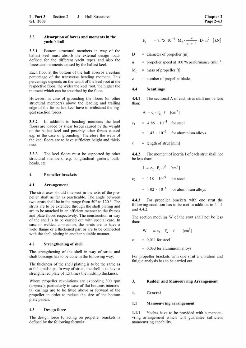
3.3 Absorption of forces and moments in the yacht's hull
3.3.1 Bottom structural members in way of the ballast keel must absorb the external design loads defined for the different yacht types and also the forces and moments caused by the ballast keel.
Each floor at the bottom of the hull absorbs a certain percentage of the transverse bending moment. This percentage depends on the width of the keel root at the respective floor; the wider the keel root, the higher the moment which can be absorbed by the floor.
However, in case of grounding the floors (or other structural members) above the leading and trailing edge of the fin ballast keel have to withstand the big-gest reaction forces.
3.3.2 In addition to bending moments the keel floors are loaded by shear forces caused by the weight of the ballast keel and possibly other forces caused e.g. in the case of grounding. Therefore the webs of the keel floors are to have sufficient height and thick-ness.
3.3.3 The keel floors must be supported by other structural members, e.g. longitudinal girders, bulk-heads, etc.
4. Propeller brackets
4.1 Arrangement
The strut axes should intersect in the axis of the pro-peller shaft as far as practicable. The angle between two struts shall be in the range from 50° to 120 °. The struts are to be extended through the shell plating and are to be attached in an efficient manner to the frames and plate floors respectively. The construction in way of the shell is to be carried out with special care. In case of welded connection, the struts are to have a weld flange or a thickened part or are to be connected with the shell plating in another suitable manner.
4.2 Strengthening of shell
The strengthening of the shell in way of struts and shaft bossings has to be done in the following way:
The thickness of the shell plating is to be the same as at 0,4 amidships. In way of struts, the shell is to have a strengthened plate of 1,5 times the midship thickness.
Where propeller revolutions are exceeding 300 rpm (approx.), particularly in case of flat bottoms intercos-tal carlings are to be fitted above or forward of the propeller in order to reduce the size of the bottom plate panels.
4.3 Design force
The design force Fu acting on propeller brackets is defined by the following formula:
[ ]4 2u p
zF 7,75 10 M D n kNz 1
−= ⋅ ⋅ ⋅ ⋅ ⋅+
D = diameter of propeller [m]
n = propeller speed at 100 % performance [min–1]
Mp = mass of propeller [t]
z = number of propeller blades
4.4 Scantlings
4.4.1 The sectional A of each strut shall not be less than:
21 uA c F [cm ]= ⋅ ⋅
c1 = 44,85 10−⋅ for steel
= 31,43 10−⋅ for aluminium alloys
= length of strut [mm]
4.4.2 The moment of inertia I of each strut shall not be less than:
3 42 uI c F [cm ]= ⋅ ⋅
c2 = 91,18 10−⋅ for steel
= 81,02 10−⋅ for aluminium alloys
4.4.3 For propeller brackets with one strut the following condition has to be met in addition to 4.4.1 and 4.4.2:
The section modulus W of the strut shall not be less than:
33 uW c F [cm ]= ⋅ ⋅
c3 = 0,011 for steel
= 0,033 for aluminium alloys
For propeller brackets with one strut a vibration and fatigue analysis has to be carried out.
J. Rudder and Manoeuvring Arrangement
1. General
1.1 Manoeuvring arrangement
1.1.1 Yachts have to be provided with a manoeu-vring arrangement which will guarantee sufficient manoeuvring capability.
I - Part 3 GL 2003
Section 2 Hull Structures Chapter 2Page 2–63
J
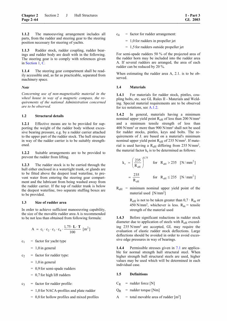
1.1.2 The manoeuvring arrangement includes all parts, from the rudder and steering gear to the steering position necessary for steering of yachts.
1.1.3 Rudder stock, rudder coupling, rudder bear-ings and rudder body are dealt with in the following. The steering gear is to comply with references given in Section 1, C.
1.1.4 The steering gear compartment shall be read-ily accessible and, as far as practicable, separated from machinery space.
Note Concerning use of non-magnetizable material in the wheel house in way of a magnetic compass, the re-quirements of the national Administration concerned are to be observed.
1.2 Structural details
1.2.1 Effective means are to be provided for sup-porting the weight of the rudder body without exces-sive bearing pressure, e.g. by a rudder carrier attached to the upper part of the rudder stock. The hull structure in way of the rudder carrier is to be suitably strength-ened.
1.2.2 Suitable arrangements are to be provided to prevent the rudder from lifting.
1.2.3 The rudder stock is to be carried through the hull either enclosed in a watertight trunk, or glands are to be fitted above the deepest load waterline, to pre-vent water from entering the steering gear compart-ment and the lubricant from being washed away from the rudder carrier. If the top of rudder trunk is below the deepest waterline, two separate stuffing boxes are to be provided.
1.3 Size of rudder area
In order to achieve sufficient manoeuvring capability, the size of the movable rudder area A is recommended to be not less than obtained from following formula:
21 2 3 4
1,75A c c c c [m ]100
⋅ ⋅= ⋅ ⋅ ⋅ ⋅
L T
c1 = factor for yacht type
= 1,0 in general
c2 = factor for rudder type:
= 1,0 in general
= 0,9 for semi-spade rudders
= 0,7 for high lift rudders
c3 = factor for rudder profile:
= 1,0 for NACA-profiles and plate rudder
= 0,8 for hollow profiles and mixed profiles
c4 = factor for rudder arrangement:
= 1,0 for rudders in propeller jet = 1,5 for rudders outside propeller jet
For semi-spade rudders 50 % of the projected area of the rudder horn may be included into the rudder area A. If several rudders are arranged, the area of each rudder can be reduced by 20 %.
When estimating the rudder area A, 2.1. is to be ob-served.
1.4 Materials
1.4.1 For materials for rudder stock, pintles, cou-pling bolts, etc. see GL Rules II - Materials and Weld-ing. Special material requirements are to be observed for ice notations, see A.1.2.
1.4.2 In general, materials having a minimum nominal upper yield point ReH of less than 200 N/mm² and a minimum tensile strength of less than 400 N/mm2 or more than 900 N/mm² shall not be used for rudder stocks, pintles, keys and bolts. The re-quirements of J. are based on a material's minimum nominal upper yield point ReH of 235 N/mm2. If mate-rial is used having a ReH differing from 235 N/mm2, the material factor kr is to be determined as follows:
0,75
2r eH
eH
235k for R 235 [N / mm ]R
⎛ ⎞= >⎜ ⎟
⎝ ⎠
2eH
eH
235 for R 235 [N / mm ]R
= ≤
ReH = minimum nominal upper yield point of the material used [N/mm2]
ReH is not to be taken greater than 0,7 · Rm or 450 N/mm2, whichever is less. Rm = tensile strength of the material used
1.4.3 Before significant reductions in rudder stock diameter due to application of steels with ReH exceed-ing 235 N/mm2 are accepted, GL may require the evaluation of elastic rudder stock deflections. Large deflections should be avoided in order to avoid exces-sive edge pressures in way of bearings.
1.4.4 Permissible stresses given in 7.1 are applica-ble for normal strength hull structural steel. When higher strength hull structural steels are used, higher values may be used which will be determined in each individual case.
1.5 Definitions
CR = rudder force [N]
QR = rudder torque [Nm]
A = total movable area of rudder [m2]
Chapter 2 Page 2–64
Section 2 Hull Structures I - Part 3GL 2003
J
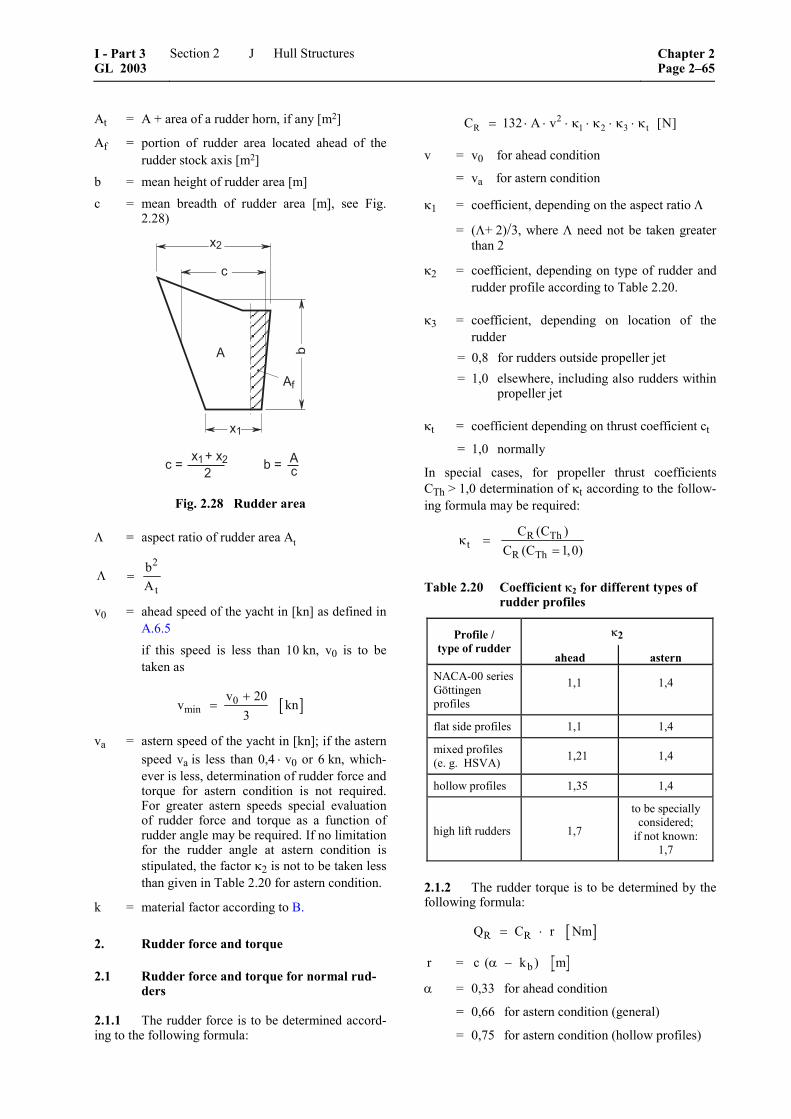
At = A + area of a rudder horn, if any [m2]
Af = portion of rudder area located ahead of the rudder stock axis [m2]
b = mean height of rudder area [m] c = mean breadth of rudder area [m], see Fig.
2.28)
��������������� � ��� /
����
/
/�
��
�
�
��
Fig. 2.28 Rudder area
Λ = aspect ratio of rudder area At
Λ =bAt
2
v0 = ahead speed of the yacht in [kn] as defined in A.6.5
if this speed is less than 10 kn, v0 is to be taken as
[ ]0min
v 20v kn
3+
=
va = astern speed of the yacht in [kn]; if the astern speed va is less than 0,4 ⋅ v0 or 6 kn, which-ever is less, determination of rudder force and torque for astern condition is not required. For greater astern speeds special evaluation of rudder force and torque as a function of rudder angle may be required. If no limitation for the rudder angle at astern condition is stipulated, the factor κ2 is not to be taken less than given in Table 2.20 for astern condition.
k = material factor according to B.
2. Rudder force and torque
2.1 Rudder force and torque for normal rud-ders
2.1.1 The rudder force is to be determined accord-ing to the following formula:
2R 1 2 3 tC 132 A v [N]= ⋅ ⋅ ⋅ κ ⋅ κ ⋅ κ ⋅ κ
v = v0 for ahead condition
= va for astern condition
κ1 = coefficient, depending on the aspect ratio Λ
= (Λ+ 2)/3, where Λ need not be taken greater than 2
κ2 = coefficient, depending on type of rudder and rudder profile according to Table 2.20.
κ3 = coefficient, depending on location of the rudder
= 0,8 for rudders outside propeller jet = 1,0 elsewhere, including also rudders within
propeller jet
κt = coefficient depending on thrust coefficient ct
= 1,0 normally
In special cases, for propeller thrust coefficients CTh > 1,0 determination of κt according to the follow-ing formula may be required:
R Tht
R Th
C (C )C (C 1,0)
κ ==
Table 2.20 Coefficient κ2 for different types of rudder profiles
κ2 Profile / type of rudder
ahead astern NACA-00 seriesGöttingen profiles
1,1 1,4
flat side profiles 1,1 1,4
mixed profiles (e. g. HSVA) 1,21 1,4
hollow profiles 1,35 1,4
high lift rudders 1,7
to be specially considered;
if not known: 1,7
2.1.2 The rudder torque is to be determined by the following formula:
[ ]R RQ C r Nm= ⋅
r = c k mb( )α −
α = 0,33 for ahead condition
= 0,66 for astern condition (general)
= 0,75 for astern condition (hollow profiles)
I - Part 3 GL 2003
Section 2 Hull Structures Chapter 2Page 2–65
J
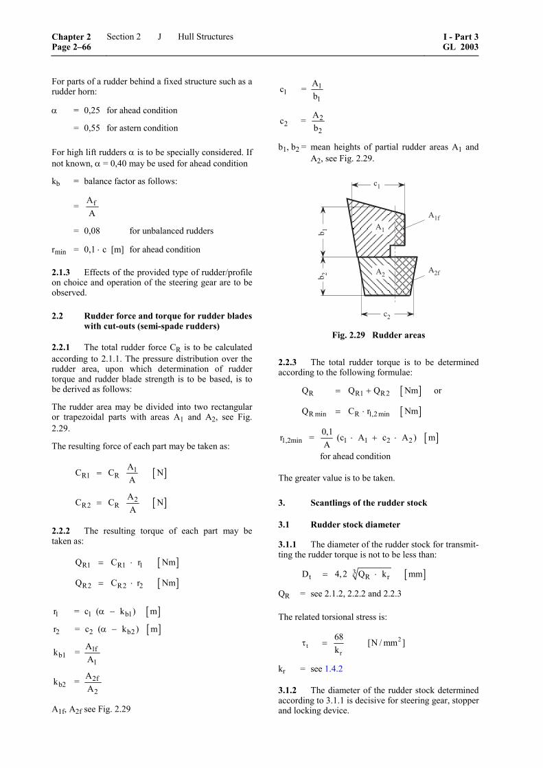
For parts of a rudder behind a fixed structure such as a rudder horn:
α = 0,25 for ahead condition
= 0,55 for astern condition
For high lift rudders α is to be specially considered. If not known, α = 0,40 may be used for ahead condition
kb = balance factor as follows:
= fAA
= 0,08 for unbalanced rudders
rmin = 0,1 ⋅ c [m] for ahead condition
2.1.3 Effects of the provided type of rudder/profile on choice and operation of the steering gear are to be observed.
2.2 Rudder force and torque for rudder blades with cut-outs (semi-spade rudders)
2.2.1 The total rudder force CR is to be calculated according to 2.1.1. The pressure distribution over the rudder area, upon which determination of rudder torque and rudder blade strength is to be based, is to be derived as follows:
The rudder area may be divided into two rectangular or trapezoidal parts with areas A1 and A2, see Fig. 2.29.
The resulting force of each part may be taken as:
[ ]
[ ]
1R1 R
2R2 R
AC C NA
AC C NA
=
=
2.2.2 The resulting torque of each part may be taken as:
[ ]
[ ]
R1 R1 1
R2 R2 2
Q C r Nm
Q C r Nm
= ⋅
= ⋅
[ ]1 1 b1r = c ( k ) mα −
[ ]2 2 b2r = c ( k ) mα −
1fb1
1
Ak =A
2fb2
2
Ak =A
A1f, A2f see Fig. 2.29
11
1
Ac =b
22
2
Ac =b
b1, b2 = mean heights of partial rudder areas A1 and A2, see Fig. 2.29.
B��
B��
B�
B�
��� �
� �
��
Fig. 2.29 Rudder areas
2.2.3 The total rudder torque is to be determined according to the following formulae:
[ ]
[ ]
R R1 R2
R min R 1,2 min
Q Q Q Nm or
Q C r Nm
= +
= ⋅
[ ]1,2min 1 1 2 20,1r = (c A c A ) mA
for ahead condition
⋅ + ⋅
The greater value is to be taken.
3. Scantlings of the rudder stock
3.1 Rudder stock diameter
3.1.1 The diameter of the rudder stock for transmit-ting the rudder torque is not to be less than:
[ ]3t R rD 4,2 Q k mm= ⋅
QR = see 2.1.2, 2.2.2 and 2.2.3
The related torsional stress is:
2t
r
68 [N / mm ]k
τ =
kr = see 1.4.2
3.1.2 The diameter of the rudder stock determined according to 3.1.1 is decisive for steering gear, stopper and locking device.
Chapter 2 Page 2–66
Section 2 Hull Structures I - Part 3GL 2003
J

3.1.3 In case of mechanical steering gear, the di-ameter of the rudder stock in its upper part, which is only intended for transmission of the torsional mo-ment from the auxiliary steering gear may be 0,9 Dt. The length of the edge of the quadrangle for the auxil-iary tiller must not be less than 0,77 Dt and the height not less than 0,8 Dt.
3.1.4 The rudder stock is to be secured against axial sliding. The degree of the permissible axial clearance depends on the construction of steering engine and bearing.
3.2 Strengthening of rudder stock
3.2.1 If the rudder is so arranged that additional bending stresses occur in the rudder stock, the stock diameter has to be suitably increased. The increased diameter is, where applicable, decisive for the scant-lings of the coupling.
For the increased rudder stock diameter the equivalent stress of bending and torsion is not to exceed the fol-lowing value:
2 2 2v b
r
1183 [N / mm ]k
σ = σ + τ ≤
Bending stress:
2bb 3
1
10,2 M[N / mm ]
D⋅
σ =
Mb = bending moment at the neck bearing [Nm]
Torsional stress:
2R31
5,1 Q[N / mm ]
D⋅
τ =
D1 = increased rudder stock diameter [cm]
The increased rudder stock diameter may be deter-mined by the following formula:
2
b61 tR
M4D 0,1 D 13 Q
⎛ ⎞= ⋅ + ⎜ ⎟
⎝ ⎠
QR = see 2.1.2, 2.2.2 and 2.2.3
Dt = see 3.1.1
Note
Where a double-piston steering gear is fitted, addi-tional bending moments may be transmitted from the steering gear into the rudder stock. These additional bending moments are to be taken into account for determining the rudder stock diameter.
3.3 Analysis
3.3.1 General
The evaluation of bending moments, shear forces and support forces for the system rudder - rudder stock may be carried out for some basic rudder types as shown in Figs. 2.30 to 2.32 as outlined in 3.3.2 to 3.3.3.
3.3.2 Data for the analysis
10 – 50 = lengths of the individual girders of the system [m]
I10 – I50 = moments of inertia of these girders [cm4]
For rudders supported by a sole piece, the length 20 is the distance between lower edge of rudder body and centre of sole piece, and I20 is the moment of inertia of the pintle in the sole piece.
Load on rudder body (general):
[ ]RR 3
10
Cp kN m10
=⋅
Load on semi-spade rudders:
[ ]
[ ]
R2R10 3
10
R1R20 3
20
Cp kN m
10
Cp kN m10
=⋅
=⋅
CR, CR1, CR2 = see 2.1 and 2.2
Z = spring constant of support in the sole piece or rudder horn respectively
for support in the sole piece (Fig. 2.30):
[ ]50350
6,18 IZ = kN m
⋅
for support in the rudder horn (Fig. 2.31):
[ ]b t
1Z = kN mf f+
fb = unit displacement of rudder horn [m] due to a unit force of 1 kN acting in the centre of sup-port
= [ ]3
n
d0, 21 m kN (guidance value for steel)I
In = moment of inertia of rudder horn around the x-axis at d/2 [cm4], see also Fig. 2.31.
I - Part 3 GL 2003
Section 2 Hull Structures Chapter 2Page 2–67
J
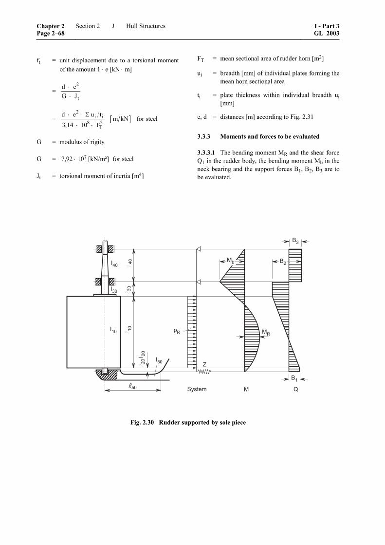
ft = unit displacement due to a torsional moment of the amount 1 ⋅ e [kN ⋅ m]
= 2
t
d eG J
⋅⋅
= [ ]2
i i8 2
T
d e u tm kN for steel
3,14 10 F⋅ ⋅ Σ
⋅ ⋅
G = modulus of rigity
G = 7,92 ⋅ 107 [kN/m²] for steel
Jt = torsional moment of inertia [m4]
FT = mean sectional area of rudder horn [m2]
ui = breadth [mm] of individual plates forming the mean horn sectional area
ti = plate thickness within individual breadth ui [mm]
e, d = distances [m] according to Fig. 2.31
3.3.3 Moments and forces to be evaluated
3.3.3.1 The bending moment MR and the shear force Q1 in the rudder body, the bending moment Mb in the neck bearing and the support forces B1, B2, B3 are to be evaluated.
0�%
1
0(%
0�%
0 �%
0'%
�2 32
�%
'% 34����� 5
6�
6(
6�3�
(%�%
�%
Fig. 2.30 Rudder supported by sole piece
Chapter 2 Page 2–68
Section 2 Hull Structures I - Part 3GL 2003
J
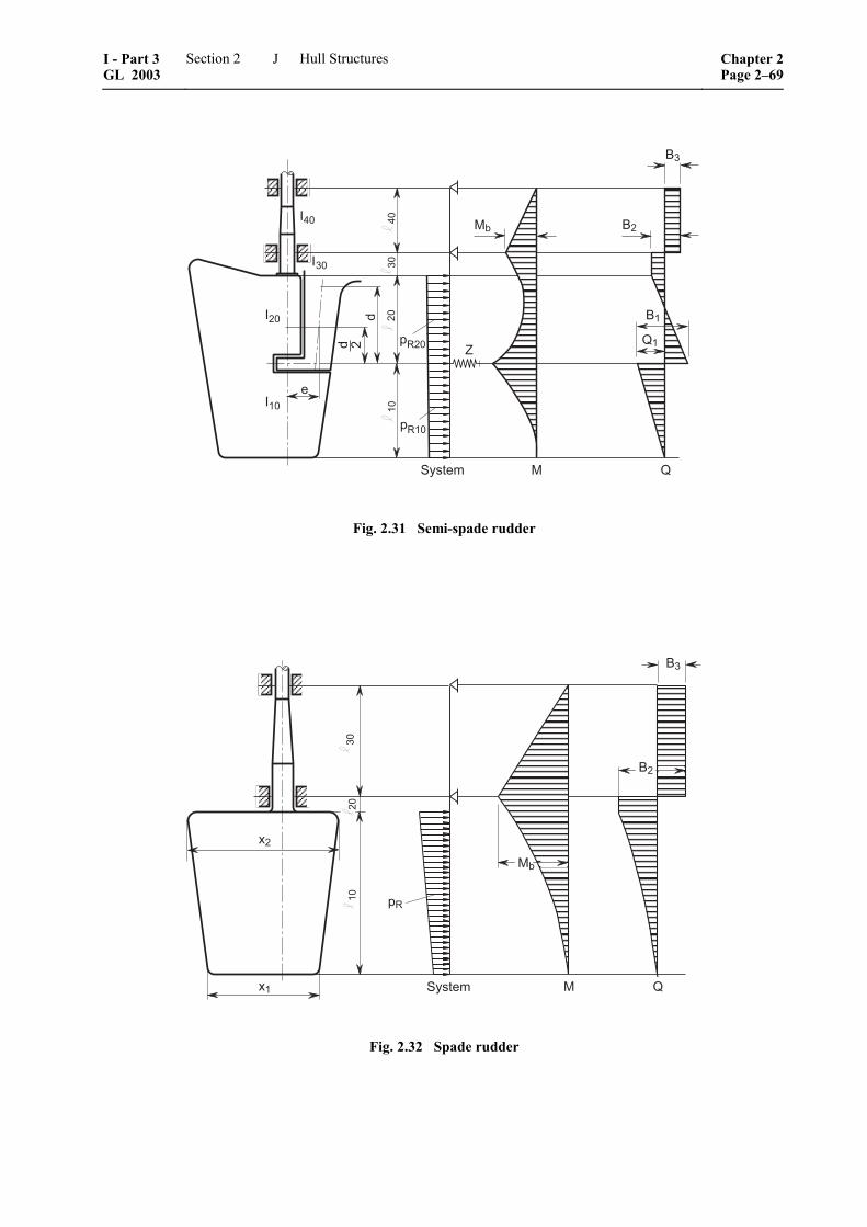
3 5
3�
6(
6�
6�
5�1� �
�
�2�%
�
0�%
0�%
0(%
0�% �%(%
�%�%
�2�%
4�����
Fig. 2.31 Semi-spade rudder
��
��
4����� 3 5
�2
(%�%
6(
6�
3�
�%
Fig. 2.32 Spade rudder
I - Part 3 GL 2003
Section 2 Hull Structures Chapter 2Page 2–69
J
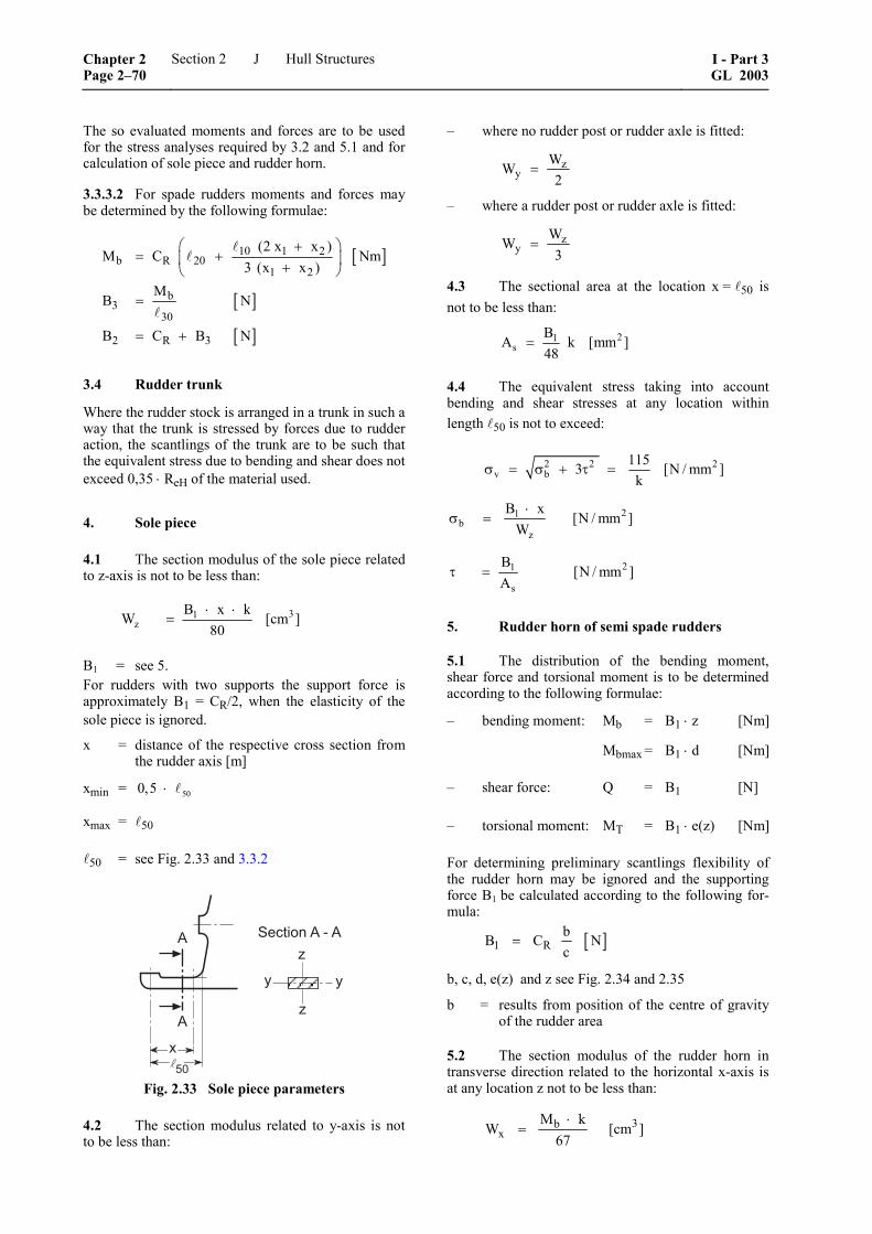
The so evaluated moments and forces are to be used for the stress analyses required by 3.2 and 5.1 and for calculation of sole piece and rudder horn.
3.3.3.2 For spade rudders moments and forces may be determined by the following formulae:
[ ]
[ ]
[ ]
10 1 2b R 20
1 2
b3
30
2 R 3
(2 x x )M C Nm
3 (x x )M
B N
B C B N
⎛ ⎞+= +⎜ ⎟+⎝ ⎠
=
= +
3.4 Rudder trunk
Where the rudder stock is arranged in a trunk in such a way that the trunk is stressed by forces due to rudder action, the scantlings of the trunk are to be such that the equivalent stress due to bending and shear does not exceed 0,35 ⋅ ReH of the material used.
4. Sole piece
4.1 The section modulus of the sole piece related to z-axis is not to be less than:
31z
B x kW [cm ]80
⋅ ⋅=
B1 = see 5. For rudders with two supports the support force is approximately B1 = CR/2, when the elasticity of the sole piece is ignored.
x = distance of the respective cross section from the rudder axis [m]
xmin = 500,5 ⋅
xmax = 50
50 = see Fig. 2.33 and 3.3.2
��
�'%
/
/ 4�������/�7�/
Fig. 2.33 Sole piece parameters
4.2 The section modulus related to y-axis is not to be less than:
– where no rudder post or rudder axle is fitted:
zy
WW2
=
– where a rudder post or rudder axle is fitted:
zy
WW3
=
4.3 The sectional area at the location x = 50 is not to be less than:
21s
BA k [mm ]48
=
4.4 The equivalent stress taking into account bending and shear stresses at any location within length 50 is not to exceed:
2 2 2v b
1153 [N / mm ]k
σ = σ + τ =
21b
z
B x[N / mm ]
W⋅
σ =
21
s
B[N / mm ]
Aτ =
5. Rudder horn of semi spade rudders
5.1 The distribution of the bending moment, shear force and torsional moment is to be determined according to the following formulae:
– bending moment: Mb = B1 ⋅ z [Nm]
Mbmax = B1 ⋅ d [Nm]
– shear force: Q = B1 [N]
– torsional moment: MT = B1 ⋅ e(z) [Nm]
For determining preliminary scantlings flexibility of the rudder horn may be ignored and the supporting force B1 be calculated according to the following for-mula:
[ ]1 RbB C Nc
=
b, c, d, e(z) and z see Fig. 2.34 and 2.35
b = results from position of the centre of gravity of the rudder area
5.2 The section modulus of the rudder horn in transverse direction related to the horizontal x-axis is at any location z not to be less than:
3bx
M kW [cm ]
67⋅
=
Chapter 2 Page 2–70
Section 2 Hull Structures I - Part 3GL 2003
J
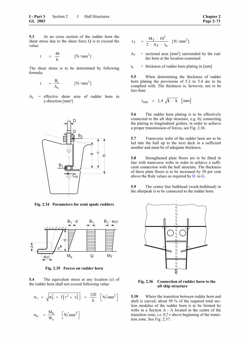
5.3 At no cross section of the rudder horn the shear stress due to the shear force Q is to exceed the value:
248 [N / mm ]k
τ =
The shear stress is to be determined by following formula:
21
h
B[N / mm ]
Aτ =
Ah = effective shear area of rudder horn in y-direction [mm²]
6�
8
8�
6�
� ��
$2
Fig. 2.34 Parameters for semi spade rudders
6����� 6�����9 :
�
�9 : 3� 5 3.
6�
Fig. 2.35 Forces on rudder horn
5.4 The equivalent stress at any location (z) of the rudder horn shall not exceed following value:
( )2 2 2 2v b T
1203 N mmk
⎡ ⎤σ = σ + τ + τ = ⎣ ⎦
2bb
x
MN mm
W⎡ ⎤σ = ⎣ ⎦
32T
TT h
M 10[N / mm ]
2 A t⋅
τ =⋅ ⋅
AT = sectional area [mm2] surrounded by the rud-der horn at the location examined
th = thickness of rudder horn plating in [mm]
5.5 When determining the thickness of rudder horn plating the provisions of 5.2 to 5.4 are to be complied with. The thickness is, however, not to be less than:
[ ]mint 2, 4 k mm= ⋅L
5.6 The rudder horn plating is to be effectively connected to the aft ship structure, e.g. by connecting the plating to longitudinal girders, in order to achieve a proper transmission of forces, see Fig. 2.36.
5.7 Transverse webs of the rudder horn are to be led into the hull up to the next deck in a sufficient number and must be of adequate thickness.
5.8 Strengthened plate floors are to be fitted in line with transverse webs in order to achieve a suffi-cient connection with the hull structure. The thickness of these plate floors is to be increased by 50 per cent above the Rule values as required by D. to G.
5.9 The centre line bulkhead (wash-bulkhead) in the afterpeak is to be connected to the rudder horn.
Fig. 2.36 Connection of rudder horn to the aft ship structure
5.10 Where the transition between rudder horn and shell is curved, about 50 % of the required total sec-tion modulus of the rudder horn is to be formed by webs in a Section A - A located in the centre of the transition zone, i.e. 0,7 r above beginning of the transi-tion zone. See Fig. 2.37.
I - Part 3 GL 2003
Section 2 Hull Structures Chapter 2Page 2–71
J
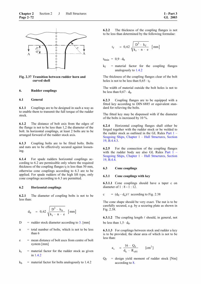
B B
�
����
Fig. 2.37 Transition between rudder horn and curved shell
6. Rudder couplings
6.1 General
6.1.1 Couplings are to be designed in such a way as to enable them to transmit the full torque of the rudder stock.
6.1.2 The distance of bolt axis from the edges of the flange is not to be less than 1,2 the diameter of the bolt. In horizontal couplings, at least 2 bolts are to be arranged forward of the rudder stock axis.
6.1.3 Coupling bolts are to be fitted bolts. Bolts and nuts are to be effectively secured against loosen-ing.
6.1.4 For spade rudders horizontal couplings ac-cording to 6.2 are permissible only where the required thickness of the coupling flanges tf is less than 50 mm, otherwise cone couplings according to 6.3 are to be applied. For spade rudders of the high lift type, only cone couplings according to 6.3 are permitted.
6.2 Horizontal couplings
6.2.1 The diameter of coupling bolts is not to be less than:
[ ]3
bb
r
D kd 0,62 mm
k n e⋅
=⋅ ⋅
D = rudder stock diameter according to 3. [mm]
n = total number of bolts, which is not to be less than 6
e = mean distance of bolt axes from centre of bolt system [mm]
kr = material factor for the rudder stock as given in 1.4.2
kb = material factor for bolts analogously to 1.4.2
6.2.2 The thickness of the coupling flanges is not to be less than determined by the following formulae:
[ ]3
ff
r
D kt 0,62 mmk n e
⋅=
⋅ ⋅
tfmin = 0,9 ⋅ db
kf = material factor for the coupling flanges analogously to 1.4.2
The thickness of the coupling flanges clear of the bolt holes is not to be less than 0,65 ⋅ tf.
The width of material outside the bolt holes is not to be less than 0,67 ⋅ db.
6.2.3 Coupling flanges are to be equipped with a fitted key according to DIN 6885 or equivalent stan-dard for relieving the bolts.
The fitted key may be dispensed with if the diameter of the bolts is increased by 10 %.
6.2.4 Horizontal coupling flanges shall either be forged together with the rudder stock or be welded to the rudder stock as outlined in the GL Rules Part 1 – Seagoing Ships, Chapter 1 – Hull Structures, Section 19, B.4.4.3.
6.2.5 For the connection of the coupling flanges with the rudder body see also GL Rules Part 1 –Seagoing Ships, Chapter 1 – Hull Structures, Section 19, B.4.4.
6.3 Cone couplings
6.3.1 Cone couplings with key
6.3.1.1 Cone couplings should have a taper c on diameter of 1 : 8 - 1 : 12.
c = (d0 – du)/ according to Fig. 2.38
The cone shape should be very exact. The nut is to be carefully secured, e.g. by a securing plate as shown in Fig. 2.38.
6.3.1.2 The coupling length should, in general, not be less than 1,5 ⋅ d0.
6.3.1.3 For couplings between stock and rudder a key is to be provided, the shear area of which is not to be less than:
2Fs
k eH1
16 Qa [cm ]
d R⋅
=⋅
QF = design yield moment of rudder stock [Nm] according to 8.
Chapter 2 Page 2–72
Section 2 Hull Structures I - Part 3GL 2003
J
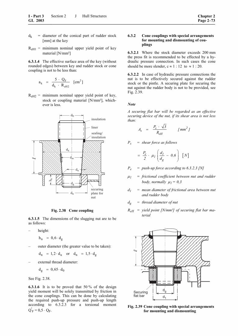
dk = diameter of the conical part of rudder stock [mm] at the key
ReH1 = minimum nominal upper yield point of key material [N/mm²]
6.3.1.4 The effective surface area of the key (without rounded edges) between key and rudder stock or cone coupling is not to be less than:
2Fk
k eH2
5 Qa [cm ]
d R⋅
=⋅
ReH2 = minimum nominal upper yield point of key, stock or coupling material [N/mm²], which-ever is less.
+'�&�(,-$)*�'����,&�
(,+&)*�(�,
)(,'�
+'*)(,-3(,+&)*�(�,
%�
%.
%&
%-
%,
2 ,
%*
Fig. 2.38 Cone coupling
6.3.1.5 The dimensions of the slugging nut are to be as follows:
– height:
n gh 0,6 d= ⋅
– outer diameter (the greater value to be taken):
n u n gd 1,2 d or d 1,5 d= ⋅ = ⋅
– external thread diameter:
g 0d 0,65 d= ⋅
See Fig. 2.38.
6.3.1.6 It is to be proved that 50 % of the design yield moment will be solely transmitted by friction in the cone couplings. This can be done by calculating the required push-up pressure and push-up length according to 6.3.2.3 for a torsional moment Q'F = 0,5 ⋅ QF.
6.3.2 Cone couplings with special arrangements for mounting and dismounting of cou-plings
6.3.2.1 Where the stock diameter exceeds 200 mm the press fit is recommended to be effected by a hy-draulic pressure connection. In such cases the cone should be more slender, c ≈ 1 : 12 to ≈ 1 : 20.
6.3.2.2 In case of hydraulic pressure connections the nut is to be effectively secured against the rudder stock or the pintle. A securing plate for securing the nut against the rudder body is not to be provided, see Fig. 2.39.
Note
A securing flat bar will be regarded as an effective securing device of the nut, if its shear area is not less than:
⋅
= 2ss
eH
P 3A [ mm ]
R
Ps = shear force as follows
[ ]e 11
g
P d0,6 N
2 dμ
⎛ ⎞= ⋅ −⎜ ⎟⎜ ⎟
⎝ ⎠
Pe = push-up force according to 6.3.2.3 [N]
μ1 = frictional coefficient between nut and rudder body, normally μ1 = 0,3
d1 = mean diameter of frictional area between nut and rudder body
dg = thread diameter of nut
ReH = yield point [N/mm²] of securing flat bar ma-terial
4��!������������ ��
��
Fig. 2.39 Cone coupling with special arrangements
for mounting and dismounting
I - Part 3 GL 2003
Section 2 Hull Structures Chapter 2Page 2–73
J
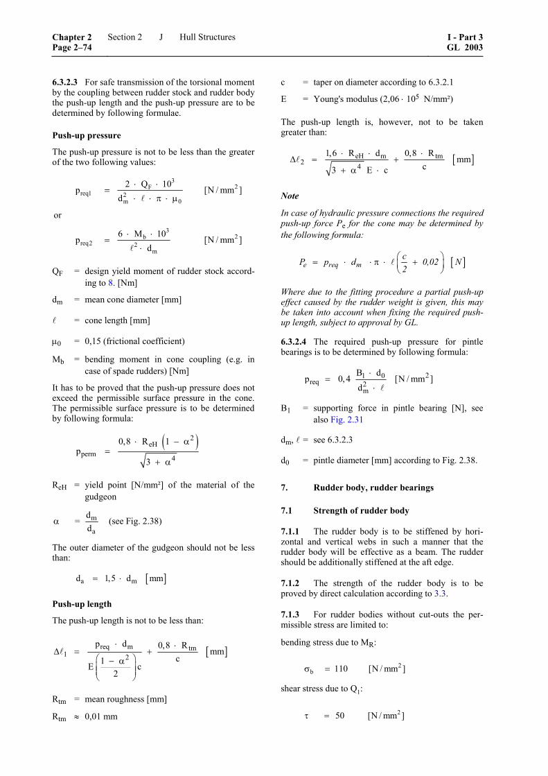
6.3.2.3 For safe transmission of the torsional moment by the coupling between rudder stock and rudder body the push-up length and the push-up pressure are to be determined by following formulae.
Push-up pressure
The push-up pressure is not to be less than the greater of the two following values:
32F
req1 2m 0
32b
req2 2m
2 Q 10p [N / mm ]
d
or
6 M 10p [N / mm ]
d
⋅ ⋅=
⋅ ⋅ π ⋅ μ
⋅ ⋅=
⋅
QF = design yield moment of rudder stock accord-ing to 8. [Nm]
dm = mean cone diameter [mm]
= cone length [mm]
μ0 = 0,15 (frictional coefficient)
Mb = bending moment in cone coupling (e.g. in case of spade rudders) [Nm]
It has to be proved that the push-up pressure does not exceed the permissible surface pressure in the cone. The permissible surface pressure is to be determined by following formula:
( )2
eHperm 4
0,8 R 1p
3
⋅ − α=
+ α
ReH = yield point [N/mm²] of the material of the gudgeon
m
a
d= (see Fig. 2.38)
dα
The outer diameter of the gudgeon should not be less than:
[ ]a md 1,5 d mm= ⋅
Push-up length
The push-up length is not to be less than:
[ ]req m tm1 2
p d 0,8 Rmm
c1E c2
⋅ ⋅Δ = +
⎛ ⎞− α⎜ ⎟⎜ ⎟⎝ ⎠
Rtm = mean roughness [mm]
Rtm ≈ 0,01 mm
c = taper on diameter according to 6.3.2.1
E = Young's modulus (2,06 ⋅ 105 N/mm²)
The push-up length is, however, not to be taken greater than:
[ ]eH m tm2 4
1,6 R d 0,8 Rmm
c3 E c
⋅ ⋅ ⋅Δ = +
+ α ⋅
Note
In case of hydraulic pressure connections the required push-up force Pe for the cone may be determined by the following formula:
[ ]⎛ ⎞= ⋅ ⋅ π ⋅ +⎜ ⎟⎝ ⎠
e req mcP p d 0,02 N2
Where due to the fitting procedure a partial push-up effect caused by the rudder weight is given, this may be taken into account when fixing the required push-up length, subject to approval by GL.
6.3.2.4 The required push-up pressure for pintle bearings is to be determined by following formula:
21 0req 2
m
B dp 0,4 [N / mm ]
d⋅
=⋅
B1 = supporting force in pintle bearing [N], see also Fig. 2.31
dm, = see 6.3.2.3
d0 = pintle diameter [mm] according to Fig. 2.38.
7. Rudder body, rudder bearings
7.1 Strength of rudder body
7.1.1 The rudder body is to be stiffened by hori-zontal and vertical webs in such a manner that the rudder body will be effective as a beam. The rudder should be additionally stiffened at the aft edge.
7.1.2 The strength of the rudder body is to be proved by direct calculation according to 3.3.
7.1.3 For rudder bodies without cut-outs the per-missible stress are limited to:
bending stress due to MR:
2b 110 [N / mm ]σ =
shear stress due to Q1:
250 [N / mm ]τ =
Chapter 2 Page 2–74
Section 2 Hull Structures I - Part 3GL 2003
J
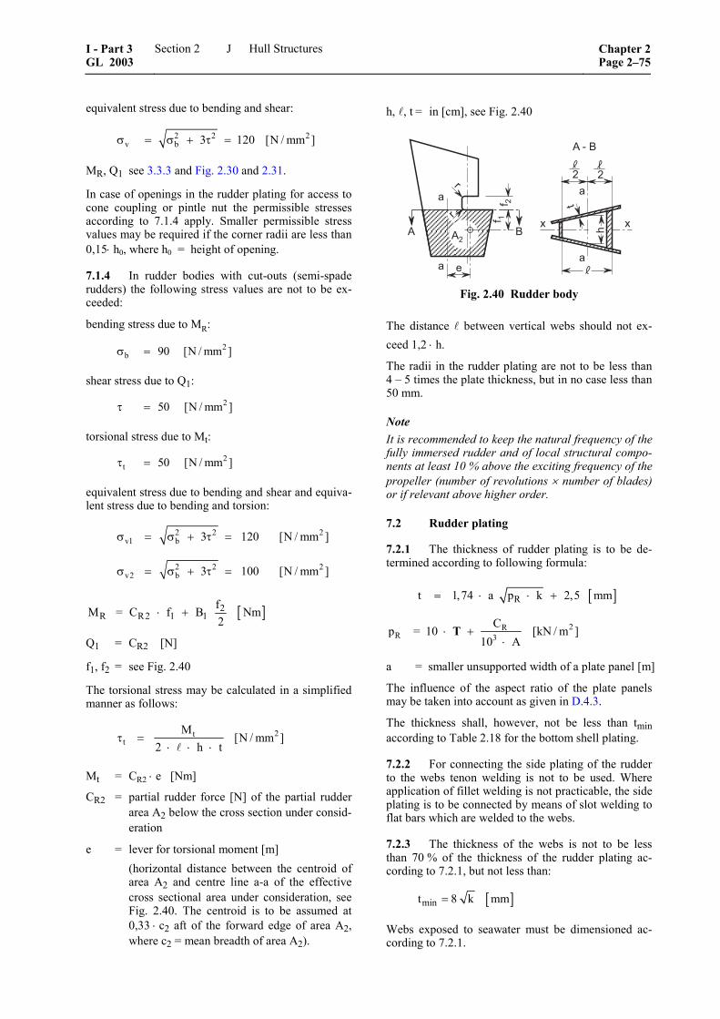
equivalent stress due to bending and shear:
2 2 2v b 3 120 [N / mm ]σ = σ + τ =
MR, Q1 see 3.3.3 and Fig. 2.30 and 2.31.
In case of openings in the rudder plating for access to cone coupling or pintle nut the permissible stresses according to 7.1.4 apply. Smaller permissible stress values may be required if the corner radii are less than 0,15⋅ h0, where h0 = height of opening.
7.1.4 In rudder bodies with cut-outs (semi-spade rudders) the following stress values are not to be ex-ceeded:
bending stress due to MR:
2b 90 [N / mm ]σ =
shear stress due to Q1:
250 [N / mm ]τ =
torsional stress due to Mt:
2t 50 [N / mm ]τ =
equivalent stress due to bending and shear and equiva-lent stress due to bending and torsion:
2 2 2v1 b
2 2 2v2 b
3 120 [N / mm ]
3 100 [N / mm ]
σ = σ + τ =
σ = σ + τ =
[ ]2R R2 1 1
fM = C f B Nm2
⋅ +
Q1 = CR2 [N]
f1, f2 = see Fig. 2.40
The torsional stress may be calculated in a simplified manner as follows:
2tt
M[N / mm ]
2 h tτ =
⋅ ⋅ ⋅
Mt = CR2 ⋅ e [Nm]
CR2 = partial rudder force [N] of the partial rudder area A2 below the cross section under consid-eration
e = lever for torsional moment [m] (horizontal distance between the centroid of
area A2 and centre line a-a of the effective cross sectional area under consideration, see Fig. 2.40. The centroid is to be assumed at 0,33 ⋅ c2 aft of the forward edge of area A2, where c2 = mean breadth of area A2).
h, , t = in [cm], see Fig. 2.40
/�7�6
/�
�
�
�
�
� �
�
�
� �
�
�
� �� �
�
/ 6
Fig. 2.40 Rudder body
The distance between vertical webs should not ex-ceed 1,2 ⋅ h.
The radii in the rudder plating are not to be less than 4 – 5 times the plate thickness, but in no case less than 50 mm.
Note It is recommended to keep the natural frequency of the fully immersed rudder and of local structural compo-nents at least 10 % above the exciting frequency of the propeller (number of revolutions × number of blades) or if relevant above higher order.
7.2 Rudder plating
7.2.1 The thickness of rudder plating is to be de-termined according to following formula:
[ ]Rt 1,74 a p k 2,5 mm= ⋅ ⋅ +
2RR 3
Cp = 10 [kN / m ]
10 A⋅ +
⋅T
a = smaller unsupported width of a plate panel [m]
The influence of the aspect ratio of the plate panels may be taken into account as given in D.4.3.
The thickness shall, however, not be less than tmin according to Table 2.18 for the bottom shell plating.
7.2.2 For connecting the side plating of the rudder to the webs tenon welding is not to be used. Where application of fillet welding is not practicable, the side plating is to be connected by means of slot welding to flat bars which are welded to the webs.
7.2.3 The thickness of the webs is not to be less than 70 % of the thickness of the rudder plating ac-cording to 7.2.1, but not less than:
[ ]mint 8 k mm=
Webs exposed to seawater must be dimensioned ac-cording to 7.2.1.
I - Part 3 GL 2003
Section 2 Hull Structures Chapter 2Page 2–75
J
7.3 Transmitting of rudder torque
7.3.1 For transmitting the rudder torque, the rudder plating according to 7.2.1 is to be increased by 25 % in way of the coupling. A sufficient number of vertical webs is to be fitted in way of the coupling.
7.3.2 If the torque is transmitted by a prolonged shaft extended into the rudder, the latter must have the diameter Dt or D1, whichever is greater, at the upper 10 % of the intersection length. Downwards it may be tapered to 0,6 Dt, in spade rudders to 0,4 times the strengthened diameter, if sufficient support is provided for.
7.4 Rudder bearings
7.4.1 In way of bearings liners and bushes are to be fitted. Where in case of small ships bushes are not fitted, the rudder stock is to be suitably increased in diameter in way of bearings enabling the stock to be re-machined later.
7.4.2 An adequate lubrication is to be provided.
7.4.3 The bearing forces result from the direct calculation mentioned in 3.3. As a first approximation the bearing force may be determined without taking account of the elastic supports. This can be done as follows:
– normal rudder with two supports:
The rudder force CR is to be distributed to the supports according to their vertical distances from the centre of gravity of the rudder area.
– semi-spade rudders:
– support force in the rudder horn:
[ ]1 RbB C Nc
= ⋅
– support force in the neck bearing:
[ ]2 R 1B C B N= −
For b and c see Fig. 2.34
7.4.4 The projected bearing surface Ab (bearing height × external diameter of liner) is not to be less than:
2b
BA [mm ]q
=
B = support force [N]
q = permissible surface pressure according to Table 2.21
7.4.5 Stainless and wear resistant steels, bronce and hot-pressed bronce-graphit materials have a consider-able difference in potential to non-alloyed steel. Re-spective preventive measures are required.
7.4.6 The bearing height shall be equal to bearing diameter, however, is not to exceed 1,2 times the bear-ing diameter. Where bearing depth is less than bearing diameter, higher specific surface pressures may be allowed.
7.4.7 The wall thickness of pintle bearings in sole piece and rudder horn shall be approximately ¼ of pintle diameter.
Table 2.21 Permissible surface pressure for bear-ing materials
Bearing material q [N/mm2]
lignum vitae 2,5
white metal, oil lubricated 4,5
synthetic material 1 5,5
steel 2, bronze and hot-pressed bronze-graphite materials
7,0
1 Synthetic materials to be of approved type.
Surface pressures exceeding 5,5 N/mm2 may be accepted in accordance with bearing manufacturer's specification and tests, but in no case more than 10 N/mm2.
2 Stainless and wear resistant steel in an approved combi-nation with stock liner. Higher surface pressures than 7 N/mm2 may be accepted if verified by tests.
7.5 Pintles
7.5.1 Pintles are to have scantlings complying with conditions given in 7.4.4 and 7.4.6. The pintle diame-ter is not to be less than:
[ ]1 rd 0,35 B k mm= ⋅
B1 = support force [N]
kr = see 1.4.2
7.5.2 The thickness of any liner or bush shall not be less than:
t = 10,01 B [mm]
Chapter 2 Page 2–76
Section 2 Hull Structures I - Part 3GL 2003
J
tmin = 8 mm for metallic materials and synthetic material
= 22 mm for lignum material
7.5.3 Where pintles are of conical shape, they are to comply with the following:
taper on diameter 1 : 8 to 1 : 12 if keyed by slugging nut
taper on diameter 1 : 12 to 1 : 20 if mounted with oil injec-tion and hydraulic nut
7.5.4 Pintles are to be arranged in such a manner as to prevent unintentional loosening and falling out.
For nuts and threads the requirements of 6.3.1.5 and 6.3.2.2 apply accordingly.
7.6 Guidance values for bearing clearances
7.6.1 For metallic bearing material the bearing clearance should generally not be less than:
[ ]bd1,0 mm
1000+
db = inner diameter of bush [mm]
7.6.2 If non-metallic bearing material is applied, the bearing clearance is to be specially determined considering the material's swelling and thermal expan-sion properties.
7.6.3 Clearance is in no way to be taken less than 1,5 mm on diameter. In case of self lubricating bushes going down below this value can be agreed to on the basis of the manufacturer's specification.
8. Design yield moment of rudder stock
The design yield moment of the rudder stock is to be determined by the following formula:
[ ]3t
Fr
DQ 0,02664 Nm
k=
Dt = stock diameter [mm] according to 3.1.
Where the actual diameter Dta is greater than the cal-culated diameter Dt, diameter Dta is to be used. How-ever, Dta need not be taken greater than 1,145 ⋅ Dt.
9. Stopper, locking device
9.1 Stopper
The motions of quadrants or tillers are to be limited on either side by stoppers. The stoppers and their founda-tions connected to the ship's hull are to be of strong construction so that the yield point of the applied materials is not exceeded at the design yield moment of the rudder stock.
9.2 Locking device
Each steering gear is to be provided with a locking device in order to keep the rudder fixed at any posi-tion. This device as well as the foundation in the ship's hull are to be of strong construction so that the yield point of the applied materials is not exceeding the design yield moment of the rudder stock as specified in 8. Where the ship's speed exceeds 12 kn, the design yield moment need only be calculated for a stock diameter based on a speed v0 = 12 kn.
10. Fin stabilizers
The structural integration of fin stabilizer systems into the hull is subject to approval.
If non-retractable fins extend over the maximum breadth of the ship their location shall be marked on the shell's side.
K. Anchor and Mooring Equipment
1. General
1.1 The equipment of anchors, chain cables, wires and ropes is to be determined from Table 2.22 in accordance with the equipment numeral EN.
Note
Anchoring equipment as required hereinafter is in-tended for temporary mooring of a yacht within a harbour or sheltered area when the yacht is awaiting berth, tide, etc.
The equipment is, therefore, not designed to hold a yacht off fully exposed coasts in rough weather or to stop a yacht which is moving or drifting. In this condi-tion the loads on the anchoring equipment increase to such a degree that its components may be damaged or lost owing to the high energy forces generated, par-ticularly in sailing yachts.
Anchoring equipment as required hereinafter is de-signed to hold a yacht in good holding ground in con-ditions such as to avoid dragging of the anchor. In poor holding ground the holding power of the anchors will be significantly reduced.
I - Part 3 GL 2003
Section 2 Hull Structures Chapter 2Page 2–77
K
The equipment numeral formula for anchoring equip-ment is based on an assumed current speed of 2,5 m/s, wind speed of 25 m/sec and a scope of chain cable between 6 and 10, the scope being the ratio between length of chain paid out and water depth.
It is assumed that under normal circumstances a yacht will use only one bow anchor and chain cable at a time.
1.2 Every yacht is to be equipped with at least one anchor windlass.
Windlass and chain stopper, if fitted, are to comply with the GL Rules Part1 – Seagoing Ships, Chapter 2 – Machinery Installations, Section 14, D.
1.3 For yachts having a navigation notation K(20) or K(50) (coastal service) affixed to their Char-acter of Classification, the equipment may be deter-mined as for one numeral range lower than required in accordance with the equipment numeral EN.
1.4 When determining the equipment for yachts having a navigation notation W (sheltered water ser-vice) affixed to their Character of Classification, the anchor mass may be 60 % of the value required by Table 2.22. The chain diameter may be determined according to the reduced anchor mass. The length of the ropes is recommended to be 50 % of the length given in Table 2.22.
1.5 Yachts built under survey of GL and which are to have the mark stated in their Certificate and in the Register Book, must be equipped with anchors and chain cables complying with the GL Rules II – Materials and Welding, Part 1 – Metallic Materials, Chapter 4 – Equipment and have to be tested on ap-proved machines in presence of a GL Surveyor.
2. Equipment numeral
2.1 For monohull yachts the equipment numeral is to be calculated as follows:
( )3 2i i iEN 2 a b h sin 0,1 A= Δ + ⋅ + ⋅ ⋅ Θ + ⋅∑B
Δ = moulded displacement [t] to design waterline in sea water with a density of 1,025 t/m3
a = distance [m], from design waterline, amid-ships, to upper deck at side, as shown in Fig. 2.41
B = greatest moulded breadth [m]
bi = actual breadth of deckhouses with a breadth greater B/4
hi = height [m] on centreline of each tier of super-structures and deckhouses corresponding to bi (deck sheer, if any, is to be ignored)
Θi = the angle of inclination aft of each front bulk-head, as shown in Fig. 2.41
A = area [m2], in profile view of the hull, super-structures and houses, having a breadth greater then B/4, above the design waterline within the length L and up to the height a + Σ hi
For sailing yachts the rig has to be appropri-ately considered when determining area A.
Note
The influence of windage effects on masts and rigging for square rigged sailing yachts on the equipment numeral be assumed as follows:
– for yachts with L < 48 m, typically 50 % in-crease in relation to a motor yacht having the same total longitudinal profile area of hull and superstructure
– for yachts with L ≥ 100 m, typically 30 % in-crease in relation to a motor yacht having the same total longitudinal profile area of hull and superstructure
– for yachts with a length in between linear inter-polation may be used
Where a deckhouse having a breadth greater than B/4 is located above a deckhouse having a breadth of B/4 or less, the wide house is to be included and the nar-row house ignored.
Windscreens or bulwarks 1,5 m or more in height above deck at side are to be regarded as parts of houses when determining h and A, e.g. the areas spe-cially marked in Fig. 2.41 are to be included in A.
2.2 For multihull yachts the equipment numeral has to be defined in analogous way, details are given in GL Rules Part 1 – Seagoing Ships, Chapter 5 – High Speed Craft, Section 6.
3. Anchors
3.1 Number and arrangement of bower anchors
3.1.1 Normally two bower anchors according to Table 2.22 have to be provided.
3.1.2 For yachts with a length L ≤ 48 m having at least two independent propulsion systems and an ade-quate steering system the following reductions may be granted: – reduction of the number of bower anchors to
one, and/or – reduction of weight of the bower anchors and
chain cables
according to a decision of GL Head Office. In this case sails are not considered as a propulsion system.
Chapter 2 Page 2–78
Section 2 Hull Structures I - Part 3GL 2003
K
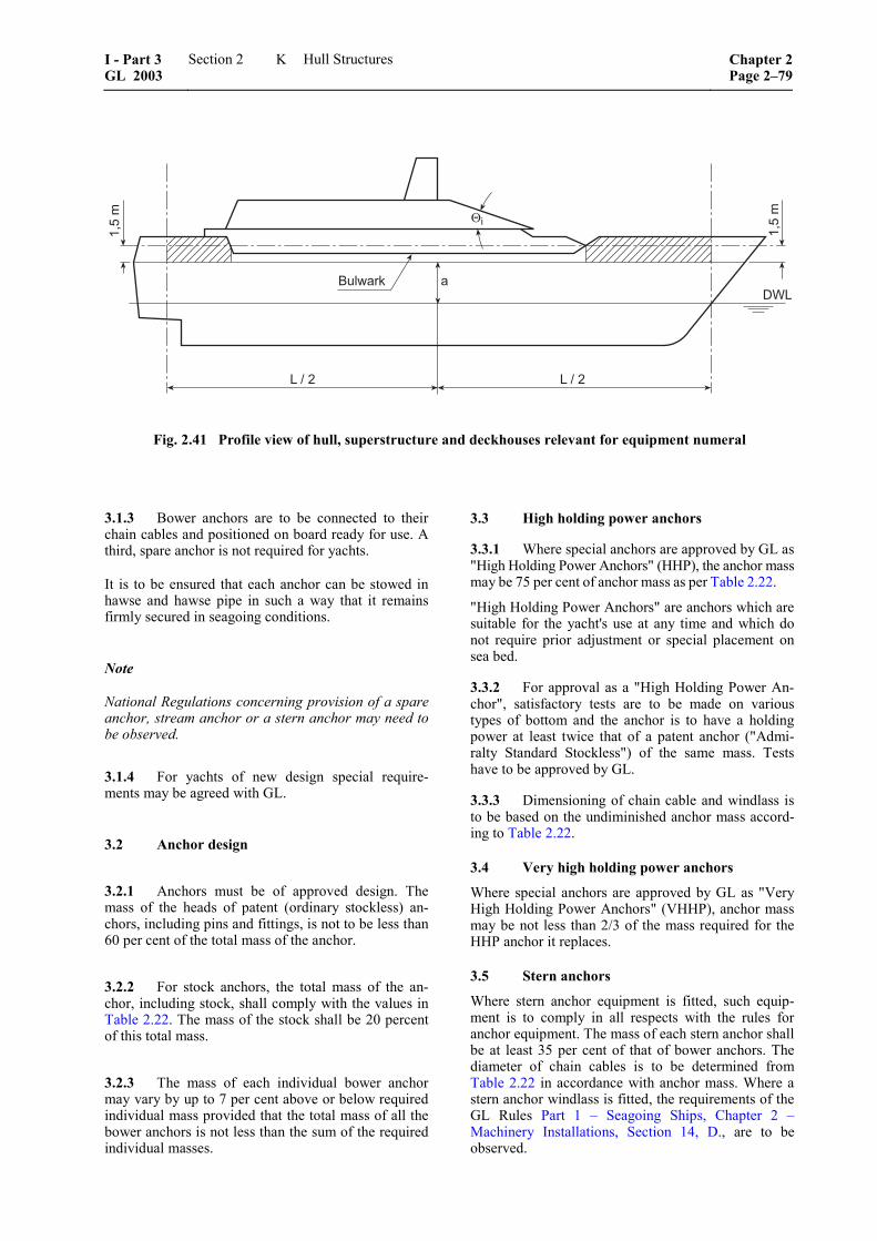
6!����;
�&'��
�&'��
8,+�
+�#�� +�#��
��
Fig. 2.41 Profile view of hull, superstructure and deckhouses relevant for equipment numeral
3.1.3 Bower anchors are to be connected to their chain cables and positioned on board ready for use. A third, spare anchor is not required for yachts.
It is to be ensured that each anchor can be stowed in hawse and hawse pipe in such a way that it remains firmly secured in seagoing conditions.
Note
National Regulations concerning provision of a spare anchor, stream anchor or a stern anchor may need to be observed.
3.1.4 For yachts of new design special require-ments may be agreed with GL.
3.2 Anchor design
3.2.1 Anchors must be of approved design. The mass of the heads of patent (ordinary stockless) an-chors, including pins and fittings, is not to be less than 60 per cent of the total mass of the anchor.
3.2.2 For stock anchors, the total mass of the an-chor, including stock, shall comply with the values in Table 2.22. The mass of the stock shall be 20 percent of this total mass.
3.2.3 The mass of each individual bower anchor may vary by up to 7 per cent above or below required individual mass provided that the total mass of all the bower anchors is not less than the sum of the required individual masses.
3.3 High holding power anchors
3.3.1 Where special anchors are approved by GL as "High Holding Power Anchors" (HHP), the anchor mass may be 75 per cent of anchor mass as per Table 2.22.
"High Holding Power Anchors" are anchors which are suitable for the yacht's use at any time and which do not require prior adjustment or special placement on sea bed.
3.3.2 For approval as a "High Holding Power An-chor", satisfactory tests are to be made on various types of bottom and the anchor is to have a holding power at least twice that of a patent anchor ("Admi-ralty Standard Stockless") of the same mass. Tests have to be approved by GL.
3.3.3 Dimensioning of chain cable and windlass is to be based on the undiminished anchor mass accord-ing to Table 2.22.
3.4 Very high holding power anchors
Where special anchors are approved by GL as "Very High Holding Power Anchors" (VHHP), anchor mass may be not less than 2/3 of the mass required for the HHP anchor it replaces.
3.5 Stern anchors
Where stern anchor equipment is fitted, such equip-ment is to comply in all respects with the rules for anchor equipment. The mass of each stern anchor shall be at least 35 per cent of that of bower anchors. The diameter of chain cables is to be determined from Table 2.22 in accordance with anchor mass. Where a stern anchor windlass is fitted, the requirements of the GL Rules Part 1 – Seagoing Ships, Chapter 2 –Machinery Installations, Section 14, D., are to be observed.
I - Part 3 GL 2003
Section 2 Hull Structures Chapter 2Page 2–79
K
4. Chain cables
4.1 Chain cable diameters given in Table 2.22 apply to chain cables made of chain cable materials specified in the requirements of the GL Rules II –Materials and Welding, Part 1 – Metallic Materials, Chapter 4 – Equipment for following grades:
– Grade K 1 (ordinary quality)
– Grade K 2 (special quality)
– Grade K 3 (extra special quality)
4.2 Grade K 1 material used for chain cables in conjunction with "High Holding Power Anchors" must have a tensile strength Rm of not less than 400 N/mm².
4.3 Grade K 2 and K 3 chain cables must be purchased from and re-heat treated by recognized manufacturers only.
4.4 The total length of chain given in Table 2.22 is to be divided in approximately equal parts between two bower anchors.
4.5 For connection of the anchor with the chain cable approved Kenter-type anchor shackles may be chosen in lieu of the common Dee-shackles. A fore-runner with swivel is to be fitted between anchor and chain cable. In lieu of a forerunner with swivel an approved swivel shackle may be used. However, swivel shackles are not to be connected to the anchor shank unless specially approved.
4.6 Steel wire and synthetic wire ropes may be used as an alternative to stud link chain cables defined in Table 2.22 for yachts upon request and agreement with GL.
4.7 The attachment of the inboard ends of chain cables to the yacht's structure is to be provided with means suitable to permit, in case of emergency, an easy slipping of chain cables to sea operable from an accessible position outside of chain locker.
Inboard ends of the chain cables are to be secured to the hull structures by a fastening able to withstand a force not less than 15 % nor more than 30 % of rated breaking load of the chain cable.
5. Chain locker
5.1 The chain locker is to be of capacity and depth adequate to provide an easy direct lead of the cables through the chain pipes and self-stowing of the cables.
The minimum required stowage capacity without mud box for the two bow anchor chains is as follows:
2 3S 1,1 d [m ]100 000
= ⋅ ⋅
d = chain diameter [mm] according to Table 2.22
= total length of stud link chain cable according to Table 2.22
The total stowage capacity is to be distributed on two chain lockers of equal size for port and starboard chain cables. The shape of the base areas shall, as far as possible, be quadratic with the maximum edge length of 33 ⋅ d. As an alternative, circular base areas may be selected, the diameter of which shall not exceed 30 –35 d.
Above the stowage of each chain locker in addition a free depth of at least
h = 750 mm for L = 24 m
h = 1 500 mm for L ≥ 48 m
is to be provided; if the size of the yacht enables this. For intermediate lengths L linear interpolation is to be applied for the depth h.
5.2 The chain locker boundaries and their access openings are to be watertight as necessary to prevent accidental flooding of the chain locker from damaging essential auxiliaries or equipment or affecting the proper operation of the yacht.
5.3 Adequate drainage facilities of chain locker are to be provided.
5.4 Where chain locker boundaries are also tank boundaries, their scantlings of stiffeners and plating are to be determined as for tanks in accordance with H.2.
Where this is not the case, plate thickness and section modulus of stiffening are also to be determined ac-cording to H.2. using the pressure p2 only. The dis-tance from the load centre to the top of chain locker pipe is to be taken for calculating the load. A corro-sion allowance of 1,5 mm has to be applied.
6. Mooring equipment
Note
For approximating mooring forces, a GL computer program system is available.
6.1 Ropes
6.1.1 The tow lines and mooring ropes specified in Table 2.22 and the content of the following up to 6.1.3 are recommendations only, a compliance with them is not a condition of Class.
Chapter 2 Page 2–80
Section 2 Hull Structures I - Part 3GL 2003
K

6.1.2 Breaking load
For tow lines and mooring lines, steel wire ropes as well as fibre ropes made of natural or synthetic fibres or wire ropes consisting of steel wire and fibre cores may be used. Nominal breaking loads specified in Table 2.22 are valid for wire ropes only. Where ropes of synthetic fibre are used, the breaking load is to be increased above the table values. The extent of in-crease depends on the material quality.
The required diameters of synthetic fibre ropes used in lieu of steel wire ropes may be taken from Table 2.23.
Regardless of the breaking load, recommended in Table 2.22, the diameter of the fibre roped should not be less than 20 mm.
6.1.3 Length
The length of the individual mooring ropes may be up to 7 per cent less than that given in Table 2.22, pro-vided that the total length of all the wires and ropes is not less than the sum of the individual lengths.
6.2 Mooring winches, bollards, hawses
6.2.1 Mooring winches are to be designed taking into account the actual mooring lines and 80 % of their nominal breaking loads.
6.2.2 Hawses, bollards and cleats shall be so de-signed as to protect the ropes against excessive wear. They are to be of proved construction and shall com-ply with relevant standards.
Note
Attention is drawn to relevant National Standards.
6.2.3 Hawses, bollards, cleats and their substruc-ture are to be strengthened, if they are intended to be belayed by multiple lines. In this case 80 % of the nominal breaking load of the individual lines has to be used as pulling forces.
L. Masts and Rigging
1. General
1.1 The requirements stated below generally apply to large motor and sailing yachts, under the condition that the yacht is handled correctly in terms of good seamanship.
1.2 The principles presented are to be seen as a general guidance. Any detailed analysis which is lead-
ing to different reserve or reduction factors can be submitted on the basis of an equivalent safety.
1.3 During the standard Classification procedure only the dimensions of the masts and the standing rigging will be checked and approved. For an ex-tended examination of the complete rigging applica-tion for a "Rig Design Certificate" has to be made.
2. Bermudian Rigging
For Bermudian rigging the GL Rules Part 4 – Special Equipment, Chapter 5 – Guidelines for Design and Construction of Large Modern Yacht Rigs are appli-cable for yachts.
Scope of these guidelines is the structural dimension-ing of standing rigging, mast and boom sections as well as local design in way of attached structural fit-tings.
3. Traditional rigging
GL has developed Rules for the following types of sailing ships, respectively yachts with traditional rig-ging:
– yachts with square rigs or fore and aft rigging
– two masted yachts, like brigs, schooner brigs, schooners
– three masted yachts, like barks, topsail schoo-ners and full rigged yachts
– four and five masts yachts, like barks and full rigged yachts.
The details for the rigging of such type are contained in the GL Rules Part 4 – Special Equipment, Chapter 2 – Rigging Design, which can fully be applied to yachts.
4. Signal and radar masts
4.1 General
4.1.1 Drawings of masts, mast substructures and hull connections are to be submitted for approval.
4.1.2 Loose component parts are to comply with the GL Rules VI – Additional Rules and Guidelines, Part 2 – Life Saving Appliances – Lifting Appliances – Towing Gears – Accesses, Chapter 2 – Guidelines for the Construction and Survey of Lifting Appliances.
4.1.3 Other masts than covered by 4.2 and 4.3 as well as special designs must, as regards dimensions and construction, in each case be individually agreed with GL.
I - Part 3 GL 2003
Section 2 Hull Structures Chapter 2Page 2–81
L
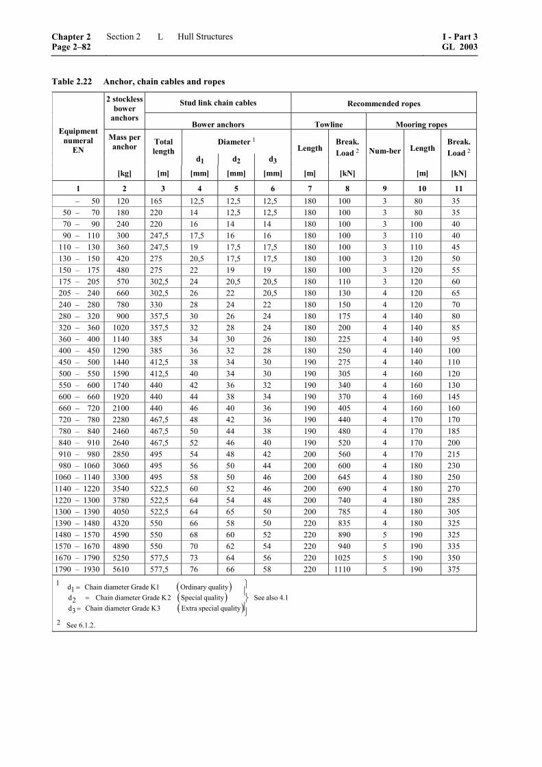
Table 2.22 Anchor, chain cables and ropes
Stud link chain cables Recommended ropes 2 stockless bower
anchors Bower anchors Towline Mooring ropes
Diameter 1 Mass per anchor Total
length d1 d2 d3
Length Break. Load 2 Length
Break. Load 2
Equipment numeral
EN
[kg] [m] [mm] [mm] [mm] [m] [kN]
Num-ber
[m] [kN]
1 2 3 4 5 6 7 8 9 10 11 – 50 120 165 12,5 12,5 12,5 180 100 3 80 35 50 – 70 180 220 14 12,5 12,5 180 100 3 80 35 70 – 90 240 220 16 14 14 180 100 3 100 40 90 – 110 300 247,5 17,5 16 16 180 100 3 110 40 110 – 130 360 247,5 19 17,5 17,5 180 100 3 110 45 130 – 150 420 275 20,5 17,5 17,5 180 100 3 120 50 150 – 175 480 275 22 19 19 180 100 3 120 55 175 – 205 570 302,5 24 20,5 20,5 180 110 3 120 60 205 – 240 660 302,5 26 22 20,5 180 130 4 120 65 240 – 280 780 330 28 24 22 180 150 4 120 70 280 – 320 900 357,5 30 26 24 180 175 4 140 80 320 – 360 1020 357,5 32 28 24 180 200 4 140 85 360 – 400 1140 385 34 30 26 180 225 4 140 95 400 – 450 1290 385 36 32 28 180 250 4 140 100 450 – 500 1440 412,5 38 34 30 190 275 4 140 110 500 – 550 1590 412,5 40 34 30 190 305 4 160 120 550 – 600 1740 440 42 36 32 190 340 4 160 130 600 – 660 1920 440 44 38 34 190 370 4 160 145 660 – 720 2100 440 46 40 36 190 405 4 160 160 720 – 780 2280 467,5 48 42 36 190 440 4 170 170 780 – 840 2460 467,5 50 44 38 190 480 4 170 185 840 – 910 2640 467,5 52 46 40 190 520 4 170 200 910 – 980 2850 495 54 48 42 200 560 4 170 215 980 – 1060 3060 495 56 50 44 200 600 4 180 230 1060 – 1140 3300 495 58 50 46 200 645 4 180 250 1140 – 1220 3540 522,5 60 52 46 200 690 4 180 270 1220 – 1300 3780 522,5 64 54 48 200 740 4 180 285 1300 – 1390 4050 522,5 64 65 50 200 785 4 180 305 1390 – 1480 4320 550 66 58 50 220 835 4 180 325 1480 – 1570 4590 550 68 60 52 220 890 5 190 325 1570 – 1670 4890 550 70 62 54 220 940 5 190 335 1670 – 1790 5250 577,5 73 64 56 220 1025 5 190 350 1790 – 1930 5610 577,5 76 66 58 220 1110 5 190 375
( )( )( )
1 d Chain diameter Grade K1 Ordinary quality1d Chain diameter Grade K2 Special quality See also 4.12d Chain diameter Grade K3 Extra special quality3
==
=
⎫⎪⎬⎪⎭
2 See 6.1.2.
Chapter 2 Page 2–82
Section 2 Hull Structures I - Part 3GL 2003
L
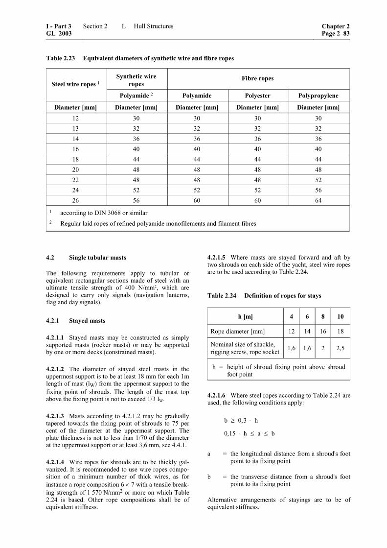
Table 2.23 Equivalent diameters of synthetic wire and fibre ropes
Synthetic wire ropes
Fibre ropes Steel wire ropes 1
Polyamide 2 Polyamide Polyester Polypropylene
Diameter [mm] Diameter [mm] Diameter [mm] Diameter [mm] Diameter [mm]
12 30 30 30 30 13 32 32 32 32 14 36 36 36 36 16 40 40 40 40 18 44 44 44 44 20 48 48 48 48 22 48 48 48 52 24 52 52 52 56 26 56 60 60 64
1 according to DIN 3068 or similar 2 Regular laid ropes of refined polyamide monofilements and filament fibres
4.2 Single tubular masts
The following requirements apply to tubular or equivalent rectangular sections made of steel with an ultimate tensile strength of 400 N/mm2, which are designed to carry only signals (navigation lanterns, flag and day signals).
4.2.1 Stayed masts
4.2.1.1 Stayed masts may be constructed as simply supported masts (rocker masts) or may be supported by one or more decks (constrained masts).
4.2.1.2 The diameter of stayed steel masts in the uppermost support is to be at least 18 mm for each 1m length of mast (lW) from the uppermost support to the fixing point of shrouds. The length of the mast top above the fixing point is not to exceed 1/3 lW.
4.2.1.3 Masts according to 4.2.1.2 may be gradually tapered towards the fixing point of shrouds to 75 per cent of the diameter at the uppermost support. The plate thickness is not to less than 1/70 of the diameter at the uppermost support or at least 3,6 mm, see 4.4.1.
4.2.1.4 Wire ropes for shrouds are to be thickly gal-vanized. It is recommended to use wire ropes compo-sition of a minimum number of thick wires, as for instance a rope composition 6 × 7 with a tensile break-ing strength of 1 570 N/mm2 or more on which Table 2.24 is based. Other rope compositions shall be of equivalent stiffness.
4.2.1.5 Where masts are stayed forward and aft by two shrouds on each side of the yacht, steel wire ropes are to be used according to Table 2.24.
Table 2.24 Definition of ropes for stays
h [m] 4 6 8 10
Rope diameter [mm] 12 14 16 18
Nominal size of shackle, rigging screw, rope socket 1,6 1,6 2 2,5
h = height of shroud fixing point above shroud foot point
4.2.1.6 Where steel ropes according to Table 2.24 are used, the following conditions apply:
b 0,3 h
0,15 h a b
≥ ⋅
⋅ ≤ ≤
a = the longitudinal distance from a shroud's foot point to its fixing point
b = the transverse distance from a shroud's foot point to its fixing point
Alternative arrangements of stayings are to be of equivalent stiffness.
I - Part 3 GL 2003
Section 2 Hull Structures Chapter 2Page 2–83
L
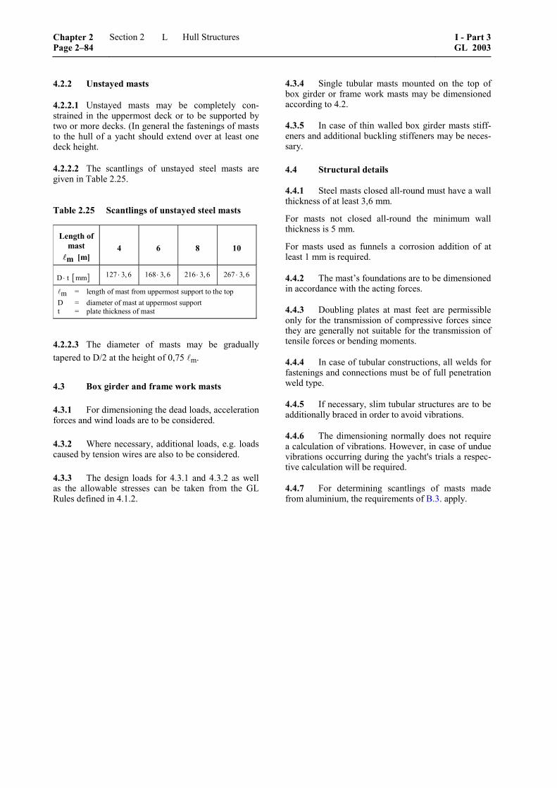
4.2.2 Unstayed masts
4.2.2.1 Unstayed masts may be completely con-strained in the uppermost deck or to be supported by two or more decks. (In general the fastenings of masts to the hull of a yacht should extend over at least one deck height.
4.2.2.2 The scantlings of unstayed steel masts are given in Table 2.25.
Table 2.25 Scantlings of unstayed steel masts
Length of mast m [m]
4 6 8 10
[ ]D t mm⋅ 127 3, 6⋅ 168 3, 6⋅ 216 3, 6⋅ 267 3, 6⋅
m = length of mast from uppermost support to the top D = diameter of mast at uppermost support t = plate thickness of mast
4.2.2.3 The diameter of masts may be gradually tapered to D/2 at the height of 0,75 m.
4.3 Box girder and frame work masts
4.3.1 For dimensioning the dead loads, acceleration forces and wind loads are to be considered.
4.3.2 Where necessary, additional loads, e.g. loads caused by tension wires are also to be considered.
4.3.3 The design loads for 4.3.1 and 4.3.2 as well as the allowable stresses can be taken from the GL Rules defined in 4.1.2.
4.3.4 Single tubular masts mounted on the top of box girder or frame work masts may be dimensioned according to 4.2.
4.3.5 In case of thin walled box girder masts stiff-eners and additional buckling stiffeners may be neces-sary.
4.4 Structural details
4.4.1 Steel masts closed all-round must have a wall thickness of at least 3,6 mm.
For masts not closed all-round the minimum wall thickness is 5 mm.
For masts used as funnels a corrosion addition of at least 1 mm is required.
4.4.2 The mast’s foundations are to be dimensioned in accordance with the acting forces.
4.4.3 Doubling plates at mast feet are permissible only for the transmission of compressive forces since they are generally not suitable for the transmission of tensile forces or bending moments.
4.4.4 In case of tubular constructions, all welds for fastenings and connections must be of full penetration weld type.
4.4.5 If necessary, slim tubular structures are to be additionally braced in order to avoid vibrations.
4.4.6 The dimensioning normally does not require a calculation of vibrations. However, in case of undue vibrations occurring during the yacht's trials a respec-tive calculation will be required.
4.4.7 For determining scantlings of masts made from aluminium, the requirements of B.3. apply.
Chapter 2 Page 2–84
Section 2 Hull Structures I - Part 3GL 2003
L
Section 3
Safety Requirements
A. Safety Appliances and Provisions
1. General
This Section summarizes various safety aspects rele-vant for the save operation of a yacht.
2. Guard-Rails
2.1 Location
Efficient guard-rails or bulwarks are to be fitted on all exposed parts of the freeboard and superstructure decks.
2.2 Heights
The height is to be at least 1,0 m from the deck (in exceptional cases for yachts of a length L ≤ 48 m at least 600 mm from the deck).
It is recommended that on each side of the yacht a toe rail at least 20 mm high is provided along the deck edge.
The height below the lowest course of the guard-rails is not to exceed 230 mm. The other courses are not to be spaced more than 380 mm apart.
2.3 Wires
Guard-rails shall consist of multi strand steel wire provided with a relevant plastic cover and equipped with a device to control their tension in an easy way. The minimum thickness of the top rail shall be at least 10 mm. The thickness of the lower rails may be re-duced by 40 %, but must be not less than 6 mm dia.
2.4 Stanchions
Guard-rail stanchions must not be more than 2,15 m apart. In case of yachts with rounded gunwales, the guard-rail supports are to be placed on the flat part of the deck. Stanchion feet must be bolted through or welded down, but may not be welded on the shell plating.
2.4.1 For yachts with 24 m ≤ L ≤ 48 m stanchions shall have the following minimum section modulus at the foot:
eH
300 a 100W hR
⋅ += ⋅
a = stanchion spacing [m]
h = stanchion height [m]
ReH = upper yield strength of material [N/mm2]
2.4.2 For yachts with L > 48 m reference is made to the GL Rules Part 1 – Seagoing Ships, Chapter 1 – Hull Structures, Section 21 regarding requirements of guard rails.
3. Access to the rig and bowsprit
Special measures are to be taken for safe access to rig and bowsprit and also for safe working thereon re-garding operation, maintenance, surveys, etc.
4. Lifting appliances
4.1 The determination of scantlings and checking of lifting gear is not part of Classification.
4.2 Approval of the hull structure in way of the lifting gear taking into account the forces from the gear is part of Classification.
Note
In all cases where GL is entrusted with the judgement of lifting gears of yachts, the GL Rules VI – Additional Rules and Guidelines, Part 2 – Lifting Appliances, Chapter 2 – Guidelines for the Construction and the Survey of Lifting Appliances will apply. Launching appliances are to comply with Chapter 1 of the above rules.
B. Structural Fire Protection
1. General
1.1 Purpose
The purpose of these Rules is to recommend design criteria, construction standards and other safety meas-ures concerning the structural fire protection of yachts with a length L ≥ 24 m.
1.2 Equivalence
Ships deviating partly from the requirements of these Rules may be assigned Class if the arrangements, material or equipment which have been applied are considered equivalent to those of the Rules.
I - Part 3 GL 2003
Section 3 Safety Requirements Chapter 2Page 3–1
B
1.3 Definitions
The meaning of terms and phrases used in these Rules corresponds with the definitions as stated in the rele-vant chapters of SOLAS 74 as amended.
2. Yachts under 500 GT and L ≤ 48 m
2.1 Structural integrity
2.1.1 Machinery spaces, galleys and storerooms containing inflammable substances shall be sur-rounded by divisions of steel or shall be protected by other equivalent methods.
2.1.2 Boundaries of control stations and of ma-chinery spaces containing internal combustion ma-chinery or other oil-burning, heating or pumping units shall be equal to an "A-60" standard, but may be re-duced to "A-30" or "A-0" if the ship operates in re-stricted or protected waters respectively. In case the adjacent spaces are of negligible fire risk, the fire integrity of the divisions needs not to exceed the "A-0" standard.
2.1.3 Escape routes shall be separated from adja-cent spaces by at least class B divisions.
2.2 Fire protection materials and details of construction
2.2.1 In general insulating materials shall be non-combustible. Where combustible insulation material is used in accessible spaces in which a fire might occur, it shall be covered with materials having at least ap-proved low-flame spread characteristics.
2.2.2 In spaces where the penetration of oil prod-ucts is possible, the surface of insulation shall be im-pervious to oil or oil vapors.
2.2.3 Combustible material if used for partitions, ceilings or linings requires adequate alternative meas-ures of fire protection. Alternative measures might be for example the installation of a fixed fire detection and fire alarm system or of an automatic sprinkler, fire detection and fire alarm system.
2.2.4 Paints, varnishes and other finishes used on exposed interior surfaces are to be of an approved low flame-spread type and shall not be capable of produc-ing excessive quantities of smoke and toxic products.
2.3 Ventilation
As far as practicable ventilation systems shall meet the requirements of 3.10. In any case the standard of the GL Rules Part 3 – Special Craft, Chapter 3 – Yachts and Boats up to 24 m shall be met at least.
2.4 Means of Escape
2.4.1 As far as practicable the means of escape shall meet the requirements in 3.11. In any case the standard of the provisions in 2.4.2 to 2.4.4 shall be met at least.
2.4.2 Stairways and ladders shall be arranged to provide ready means of escape to the open deck and then to the survival craft from all accommodation, service and other spaces which may normally be oc-cupied.
2.4.3 As far as practicable not less than two means of escape shall be provided. Dead-end situations ex-ceeding 7 m in length shall be avoided in any case. Accommodation spaces or groups of spaces shall have two means of escape unless there is a means of escape that leads directly to the open deck.
2.4.4 Below the lowest open deck at least one means of escape shall be independent of watertight doors.
3. Yachts of 500 GT and over and L > 48 m
3.1 General
The requirements of 3. are additional to those of 2. The requirements of 3. take precedence over 2.
3.2 Structural integrity
3.2.1 The hull, superstructures, structural bulk-heads, decks and deckhouses shall be constructed of steel or other equivalent material. Special fire protec-tion precautions are required if parts or all of the aforementioned structural elements are consisting of materials other than steel or other equivalent material.
3.2.2 Unless otherwise specified in 2.2.1, in cases where any part of the structure is of aluminium alloy, the following shall apply:
– The insulation of aluminium alloy components of "A" or "B" class divisions, except structure which, in the opinion of GL, is non-load-bearing, shall be such that the temperature of the structural core does not rise more than 200 °C above the ambient temperature at any time dur-ing the applicable fire exposure to the standard fire test.
– Special attention shall be given to the insulation of aluminium alloy components of columns, stanchions and other structural members re-quired to support lifeboat and liferaft stowage, launching and embarkation areas, and A and B class divisions to ensure:
Chapter 2 Page 3–2
Section 3 Safety Requirements I - Part 3GL 2003
B
– that for such members supporting lifeboat and liferaft areas and "A" class divisions, the temperature rise limitation specified in above shall apply at the end of one hour
– that for such members required to support B class divisions, the temperature rise limitation specified in above shall apply at the end of half an hour.
3.2.3 Crowns and casings of machinery spaces of category A shall be of steel construction and shall be insulated as required by Table 3.1, as appropriate. For vessels under 1 000 GT the steel construction is not required provided the relevant divisions are of "A-60" standard and an approved method for boundary cool-ing is available that operates also under emergency power supply.
3.2.4 The floor plating of normal passageways in machinery spaces of category A shall be made of steel.
3.2.5 Materials readily rendered ineffective by heat shall not be used for overboard scuppers, sanitary discharges, and other outlets which are close to the waterline and where the failure of the material in the event of fire would give rise to danger of flooding.
3.3 Main vertical zones and horizontal zones
3.3.1 The hull, superstructure and deckhouses in way of accommodation and service spaces shall be subdivided into main vertical zones by "A" class divi-sions, the mean length and width of which on any deck does not in general exceed 40 m. These divisions shall have insulation values in accordance with Tables 3.1 and 3.2.
3.3.2 As far as practicable, the bulkheads forming the boundaries of the main vertical zones above the bulkhead deck shall be in line with watertight subdivi-sion bulkheads situated immediately below the bulk-head deck. The length and width of main vertical zones may be extended to a maximum of 48 m in order to bring the ends of main vertical zones to coin-cide with watertight subdivision bulkheads or in order to accommodate a large public space extending for the whole length of the main vertical zone provided that the total area of the main vertical zone is not greater than 1 600 m2on any deck. The length or width of a main vertical zone is the maximum distance between the furthermost points of the bulkheads bounding it.
3.3.3 Such bulkheads shall extend from deck to deck and to the shell or other boundaries.
3.3.4 Where a main vertical zone is subdivided by horizontal "A" class divisions into horizontal zones for the purpose of providing an appropriate barrier be-tween a zone with sprinklers and a zone without sprinklers, the divisions shall extend between adjacent
main vertical zone bulkheads and to the shell or exte-rior boundaries of the ship and shall be insulated in accordance with the fire insulation and integrity values given in Table 3.2.
3.4 Fire integrity of bulkheads and decks
3.4.1 Yachts shall be subdivided into spaces by thermal and structural divisions having regard to the fire risk of the space.
3.4.2 Bulkheads required to be "B" class divisions shall extend from deck to deck and to the shell or other boundaries. However, where a continuous "B" class ceiling or lining is fitted on both sides of the bulkhead, the bulkhead may terminate at the continu-ous ceiling or lining.
3.4.3 Bulkheads not required to be "A" or "B" class divisions, shall be at least "C" class construction.
3.4.4 In addition to complying with the specific provisions for the fire integrity of bulkheads and decks, the minimum fire integrity of bulkheads and decks shall be as described in Tables 3.1 and 3.2.
In the Tables 3.1 and 3.2 the classification of space use is defined using the following numbers for differ-ent types of spaces:
[1] Control stations
Spaces containing emergency sources of power and lighting, wheelhouse and chartroom, spaces containing the ship's radio equipment, fire control stations, con-trol room for propulsion machinery when located outside the machinery space, spaces containing cen-tralized fire alarm equipment
[2] Corridors
Corridors and lobbies
[3] Accommodation spaces
Spaces used for public spaces, lavatories, cabins, of-fices, hospitals, cinemas, game and hobby rooms, barber shops, pantries containing no cooking appli-ances and similar spaces
[4] Stairways
Interior stairway, lifts, totally enclosed emergency escape trunks, and escalators (other than those wholly contained within the machinery spaces) and enclo-sures thereto. In this connection, a stairway which is enclosed only at one level shall be regarded as part of the space from which it is not separated by a fire door
[5] Service spaces (low risk)
Lockers and store-rooms not having provisions for the storage of flammable liquids and having areas less than 4 m2 and drying rooms and laundries
I - Part 3 GL 2003
Section 3 Safety Requirements Chapter 2Page 3–3
B
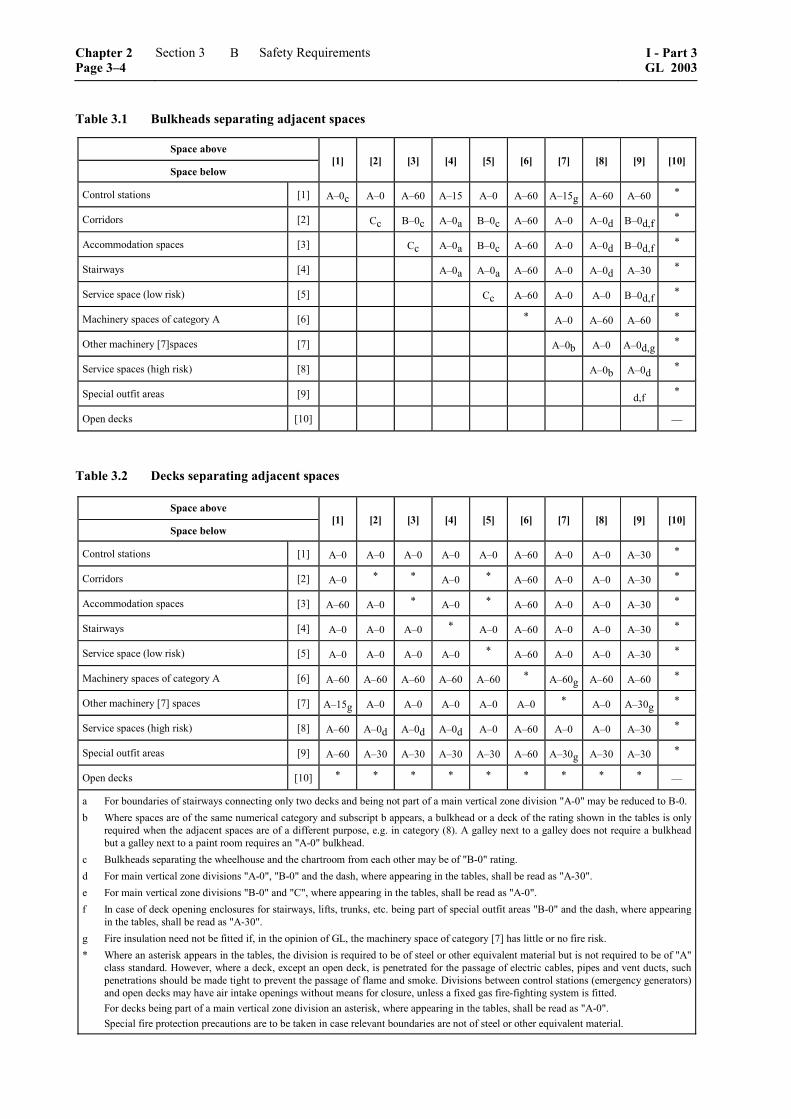
Table 3.1 Bulkheads separating adjacent spaces
Space above Space below
[1] [2] [3] [4] [5] [6] [7] [8] [9] [10]
Control stations [1] A–0c A–0 A–60 A–15 A–0 A–60 A–15g A–60 A–60 *
Corridors [2] Cc B–0c A–0a B–0c A–60 A–0 A–0d B–0d,f *
Accommodation spaces [3] Cc A–0a B–0c A–60 A–0 A–0d B–0d,f *
Stairways [4] A–0a A–0a A–60 A–0 A–0d A–30 *
Service space (low risk) [5] Cc A–60 A–0 A–0 B–0d,f *
Machinery spaces of category A [6] * A–0 A–60 A–60 *
Other machinery [7]spaces [7] A–0b A–0 A–0d,g *
Service spaces (high risk) [8] A–0b A–0d *
Special outfit areas [9] d,f *
Open decks [10] ––
Table 3.2 Decks separating adjacent spaces
Space above Space below
[1] [2] [3] [4] [5] [6] [7] [8] [9] [10]
Control stations [1] A–0 A–0 A–0 A–0 A–0 A–60 A–0 A–0 A–30 *
Corridors [2] A–0 * * A–0 * A–60 A–0 A–0 A–30 *
Accommodation spaces [3] A–60 A–0 * A–0 * A–60 A–0 A–0 A–30 *
Stairways [4] A–0 A–0 A–0 * A–0 A–60 A–0 A–0 A–30 *
Service space (low risk) [5] A–0 A–0 A–0 A–0 * A–60 A–0 A–0 A–30 *
Machinery spaces of category A [6] A–60 A–60 A–60 A–60 A–60 * A–60g A–60 A–60 *
Other machinery [7] spaces [7] A–15g A–0 A–0 A–0 A–0 A–0 * A–0 A–30g *
Service spaces (high risk) [8] A–60 A–0d A–0d A–0d A–0 A–60 A–0 A–0 A–30 *
Special outfit areas [9] A–60 A–30 A–30 A–30 A–30 A–60 A–30g A–30 A–30 *
Open decks [10] * * * * * * * * * ––
a For boundaries of stairways connecting only two decks and being not part of a main vertical zone division "A-0" may be reduced to B-0. b Where spaces are of the same numerical category and subscript b appears, a bulkhead or a deck of the rating shown in the tables is only
required when the adjacent spaces are of a different purpose, e.g. in category (8). A galley next to a galley does not require a bulkhead but a galley next to a paint room requires an "A-0" bulkhead.
c Bulkheads separating the wheelhouse and the chartroom from each other may be of "B-0" rating. d For main vertical zone divisions "A-0", "B-0" and the dash, where appearing in the tables, shall be read as "A-30". e For main vertical zone divisions "B-0" and "C", where appearing in the tables, shall be read as "A-0". f In case of deck opening enclosures for stairways, lifts, trunks, etc. being part of special outfit areas "B-0" and the dash, where appearing
in the tables, shall be read as "A-30". g Fire insulation need not be fitted if, in the opinion of GL, the machinery space of category [7] has little or no fire risk. * Where an asterisk appears in the tables, the division is required to be of steel or other equivalent material but is not required to be of "A"
class standard. However, where a deck, except an open deck, is penetrated for the passage of electric cables, pipes and vent ducts, such penetrations should be made tight to prevent the passage of flame and smoke. Divisions between control stations (emergency generators) and open decks may have air intake openings without means for closure, unless a fixed gas fire-fighting system is fitted.
For decks being part of a main vertical zone division an asterisk, where appearing in the tables, shall be read as "A-0". Special fire protection precautions are to be taken in case relevant boundaries are not of steel or other equivalent material.
Chapter 2 Page 3–4
Section 3 Safety Requirements I - Part 3GL 2003
B
[6] Machinery spaces of category A
Machinery spaces of category A are those spaces and trunks to such spaces which contain either:
– internal combustion machinery used for main propulsion
– internal combustion machinery used for pur-poses other than main propulsion where such machinery has in the aggregate a total power output of not less than 375 kW; or
– any oil-fired boiler or oil fuel unit, or any oil-fired equipment other than boilers, such as inert gas generators, incinerators, etc.
[7] Other machinery spaces
Machinery spaces containing propulsion machinery, boilers, oil fuel units, steam and internal combustion engines, generators and major electrical machinery, oil filling stations, refrigerating, stabilizing, ventila-tion and air conditioning machinery, and similar spaces, and trunks to such spaces.
Electrical equipment rooms (auto-telephone ex-change, air-conditioning duct spaces)
[8] Service spaces (high risk)
Galleys, pantries containing cooking appliances, saunas, paint lockers and store-rooms having areas of 4 m2 or more, spaces for the storage of flammable liquids, and workshops other than those forming part of the machinery spaces.
[9] Special outfit spaces
Spaces as per 3.9
[10] Open decks
Open deck spaces and enclosed promenades having little or no fire risk. To be considered in this category, enclosed promenades shall have no significant fire risk, meaning that furnishings shall be restricted to deck furniture. In addition, such spaces shall be natu-rally ventilated by permanent openings.
Air spaces (the space outside superstructures and deckhouses).
3.4.5 Continuous "B" class ceilings or linings, in association with the relevant decks or bulkheads, may be accepted as contributing, wholly or in part, to the required insulation and integrity of a division.
3.4.6 External boundaries which are required to be of steel or other equivalent material may be pierced for the fitting of windows and sidescuttles. Similarly, in such boundaries which are not required to have "A" class integrity, doors may be constructed of ap-proved materials other than steel.
3.4.7 Saunas shall comply with the following:
– The perimeter of the sauna shall be of "A" class boundaries and may include changing rooms, showers and toilets. The sauna shall be insu-lated to "A-60" standard against other spaces except those inside of the perimeter and open deck spaces, sanitary spaces and machinery spaces having little or no fire risk.
– Bathrooms with direct access to saunas may be considered as part of them. In such cases, the door between sauna and the bathroom need not comply with fire safety requirements.
– The traditional wooden lining on the bulkheads and ceiling are permitted in the sauna. The ceil-ing above the oven shall be lined with a non-combustible plate with an air gap of at least 30 mm. The distance from the hot surfaces to combustible materials shall be at least 500 mm or the combustible materials shall be protected (e.g. non-combustible plate with an air gap of at least 30 mm).
– The traditional wooden benches are permitted to be used in the sauna.
– The sauna door shall open outwards by push-ing.
– Electrically heated ovens shall be provided with a timer.
3.4.8 Stairways which penetrate only a single deck shall be protected, at a minimum, at one level by at least "B-0" class divisions and self-closing doors. Lifts which penetrate only a single deck shall be surrounded by "A-0" class divisions with steel doors at both levels. Stairways and lift trunks which pene-trate more than a single deck shall be surrounded by at least "A-0" class divisions and be protected by self-closing doors at all levels.
3.4.9 On yachts having accommodation for 12 persons or less, where stairways penetrate more than a single deck and where there are at least two escape routes direct to the open deck at every accommoda-tion level, the "A-0" requirements of 3.4.8 may be reduced to "B-0".
3.5 Penetration in fire-resisting divisions and prevention of heat transmission
3.5.1 Where "A" class divisions are penetrated, such penetrations shall be of an approved type. In case of ventilation ducts 3.10.2 and 3.10.5 apply. However, pipe penetrations made of steel or equiva-lent material having a thickness of 3 mm or greater and a length of not less than 900 mm (preferably 450 mm on each side of the division), and no open-ings, is considered as an approved type. Such pene-trations shall be suitably insulated by extension of the insulation at the same level as the division.
I - Part 3 GL 2003
Section 3 Safety Requirements Chapter 2Page 3–5
B
3.5.2 Where "B" class divisions are penetrated for the passage of electric cables, pipes, trunks, ducts, etc., or for the fitting of ventilation terminals, lighting fixtures and similar devices, arrangements shall be made to ensure that the fire resistance is not impaired, subject to the provisions of 3.10.6. Pipes other than steel or copper that penetrate "B" class divisions shall be protected by either:
– an approved penetration device, suitable for the fire resistance of the division pierced and the type of pipe used; or
– a steel sleeve, having a thickness of not less than 1,8 mm and a length of not less than 900 mm for pipe diameters of 150 mm or more and not less than 600 mm for pipe diameters of less than 150 mm (preferably equally divided to each side of the division). The pipe shall be connected to the ends of the sleeve by flanges or couplings; or the clearance between the sleeve and the pipe shall not exceed 2,5 mm; or any clearance between pipe and sleeve shall be made tight by means of non-combustible or other suitable material.
3.5.3 Uninsulated metallic pipes penetrating "A" or "B" class divisions shall be of materials having a melting temperature which exceeds 950 °C for "A-0" and 850 °C for "B-0" divisions.
3.5.4 With regard to the risk of heat transmission at intersections and terminal points of required ther-mal barriers, the insulation of a deck or bulkhead shall be carried past the penetration, intersection or terminal point for a distance of at least 450 mm in the case of steel and aluminium structures. If a space is divided with a deck or bulkhead of "A" class standard having insulation of different values, the insulation with the higher value shall continue on the deck or bulkhead with the insulation of the lesser value for a distance of at least 450 mm.
3.6 Doors in fire-resisting divisions
3.6.1 The fire resistance of doors shall be equiva-lent to that of the division in which they are fitted, this being proved by using doors of an approved type. Doors and door frames in "A" class divisions shall be constructed of steel or other equivalent material. Doors in "B" class divisions shall be non-combustible. Doors fitted in boundary bulkheads of machinery spaces of category A shall be reasonable gas-tight and self-closing. The use of combustible materials in doors separating cabins from individual interior sanitary accommodation, such as showers, may be permitted.
3.6.2 Fire doors in main vertical zone bulkheads and stairway enclosures other than power-operated watertight doors and those which are normally locked shall be self-closing.
3.6.3 Doors required to be self-closing shall not be fitted with hold-back hooks. However, hold-back arrangements as well as power-operated drive facili-ties fitted with remote release devices of the fail-safe type may be utilized.
3.6.4 In corridor bulkheads ventilation openings may be permitted in and under doors of cabins and public spaces. Ventilation openings are also permit-ted in B class doors leading to lavatories, offices, pantries, lockers and store rooms. Except as permit-ted below, the openings shall be provided only in the lower half of the door. Where such an opening is under a door the total net area of any such opening or openings shall not exceed 0,05 m2. Alternatively, a non-combustible air balance duct routed between the cabin and the corridor, and located below the sanitary unit is permitted where the cross-sectional area of the duct does not exceed 0,05 m2. Ventilation openings, except those under the door, shall be fitted with a grille made of non-combustible material.
3.6.5 Watertight doors need not be insulated.
3.7 Fire protection materials and details of construction
3.7.1 Insulating materials shall be non-combustible, except in baggage rooms and refriger-ated compartments of service spaces. Vapor barriers and adhesives used in conjunction with insulation, as well as the insulation of pipe fittings for cold service systems, need not be of non-combustible materials, but they shall be kept to the minimum quantity prac-ticable and their exposed surfaces shall have ap-proved low flame-spread characteristics.
3.7.2 In spaces where penetration of oil products is possible, the surface of insulation shall be impervi-ous to oil or oil vapors.
3.7.3 In accommodation and service spaces and control stations all linings, ceilings, draught stops and their associated grounds shall be of non-combustible materials.
3.7.4 Non-combustible bulkheads, ceilings and linings fitted in accommodation and service spaces may be faced with combustible materials, facings, mouldings, decorations and veneers in accordance with the provisions of 3.7.5 to 3.7.8. However, tradi-tional wooden benches and wooden linings on bulk-heads and ceilings are permitted in saunas and such materials need not be subject to the calculations pre-scribed in 3.7.5 and 3.7.6.
3.7.5 Combustible materials used on the surfaces and linings specified in 3.7.4 shall have a calorific value not exceeding 45 MJ/m2 of the area for the thickness used. The requirements of this paragraph are not applicable to the surfaces of furniture fixed to linings or bulkheads.
Chapter 2 Page 3–6
Section 3 Safety Requirements I - Part 3GL 2003
B
3.7.6 Where combustible materials are used in accordance with 3.7.4, they shall comply with the following requirements:
– The total volume of combustible facings, mouldings, decorations and veneers in any ac-commodation and service space not protected by an approved automatic sprinkler, fire detec-tion and fire alarm system shall not exceed a volume equivalent to 2,5 mm veneer on the combined area of the walls and ceiling linings. Furniture fixed to linings, bulkheads or decks need not be included in the calculation of the total volume of combustible materials.
– In the case of yachts fitted with an approved automatic sprinkler, fire detection and fire alarm system, the above volume may include some combustible material used for erection of "C" class divisions.
3.7.7 The following surfaces shall have approved low flame-spread characteristics:
– exposed surfaces in corridors and stairway enclosures and of ceilings in accommodation and service spaces (except saunas) and control stations
– surfaces and grounds in concealed or inaccessi-ble spaces in accommodation and service spaces and control stations
3.7.8 Paints, varnishes and other finishes used on exposed interior surfaces shall not be capable of producing excessive quantities of smoke and toxic products, this being determined in accordance with approved procedures.
3.7.9 Primary deck coverings, if applied within accommodation and service spaces and control sta-tions, shall be of approved material which will not give rise to smoke or toxic or explosive hazards at elevated temperatures, this being determined in ac-cordance with approved procedures.
3.7.10 Primary deck coverings, if applied within accommodation and service spaces and control sta-tions, shall be of approved material which will not readily ignite, this being determined in accordance with approved procedures.
3.7.11 Air spaces enclosed behind ceilings, panel-ling or linings shall be divided by close-fitting draught stops spaced not more than 14 m apart. In the vertical direction, such enclosed air spaces, including those behind linings of stairways, trunks, etc., shall be closed at each deck.
3.8 Fire detection and alarm
A fixed fire detection and fire alarm system of an approved type shall be so installed and arranged as to provide smoke detection in all corridors, stairways
and escape routes within accommodation spaces, see Part 1 – Seagoing Ships, Chapter 3 – Electrical Instal-lations, Section 9, D.3.
3.9 Alternative approach to the structural fire protection of accommodation and ser-vice spaces with special outfit
3.9.1 In lieu of complying with the requirements of 3.4.3 and 3.7.3 to 3.7.7, the following regulations may apply to restricted areas of accommodation and service spaces with special outfit.
3.9.2 There may be no restriction on the construc-tion of bulkheads not required by this or other regula-tions to be "A", "B" or "C" class divisions, except in individual cases where fire-rated bulkheads are re-quired in accordance with Table 3.1.
3.9.3 The boundary decks of special outfit spaces shall be of "A-30" standard, unless 3.4 requires a higher standard. Enclosures of deck openings for stairways, lifts, trunks, etc. are to be protected to the same standard.
3.9.4 Main vertical zone divisions shall be of "A-30" standard if special outfit spaces are adjacent, unless 3.4 requires a higher standard.
3.9.5 Corridors and stairway enclosures serving accommodation and service spaces must not be part of the special outfit areas, unless there are means of escape from those spaces that lead directly to the open deck.
3.9.6 In addition to complying with the specific provisions for the fire integrity of bulkheads and decks, the minimum fire integrity of bulkheads and decks shall be as described in Table 3.1 and 3.2.
3.9.7 Areas with special outfit spaces shall be readily accessible for fire-fighting purposes.
3.9.8 An automatic sprinkler, fire detection and fire alarm system of an approved type shall be so installed and arranged as to protect all special outfit spaces, except spaces which afford no substantial fire risk such as void spaces, sanitary spaces, etc. In addi-tion, an approved fixed fire detection and fire alarm system shall be so installed and arranged as to pro-vide smoke detection in the same spaces.
3.9.9 Provided that the area of the special outfit space or spaces is bounded by a continuous "A" or "B" class division not exceeding 50 m2, in lieu of complying with the requirements of 3.9.8, a fixed fire detection and fire alarm system of an approved type shall be so installed and arranged as to detect the presence of fire in all special outfit spaces, providing smoke detection in such spaces, except spaces which afford no substantial fire risk such as void spaces, sanitary spaces, etc.
I - Part 3 GL 2003
Section 3 Safety Requirements Chapter 2Page 3–7
B
3.10 Ventilation systems
3.10.1 Ventilation ducts shall be of non-combustible material. However, short ducts, not gen-erally exceeding 2 m in length and with a free cross-sectional area not exceeding 0,02 m2, need not be non-combustible subject to the following conditions:
– The ducts are made of a material which has low flame-spread characteristics.
– The ducts are only used at the end of the venti-lation device.
– The ducts are not situated less than 600 mm, measured along the duct, from an opening in an "A" or "B" class division including continuous "B" class ceiling.
3.10.2 The following arrangements shall be tested in accordance with approved methods:
– fire dampers, including their relevant means of operation
– duct penetrations through "A" class divisions. However, the test is not required where steel sleeves are directly joined to ventilation ducts by means of riveted or screwed flanges or by welding.
3.10.3 The ventilation systems for machinery spaces of category A and galleys shall, in general, be separated from each other and from the ventilation systems serving other spaces. Except that the galley ventilation systems on ships of less than 4 000 gross tonnage, need not be completely separated, but may be served by separate ducts from a ventilation unit serving other spaces. In any case, an automatic fire damper shall be fitted in the galley ventilation duct near the ventilation unit. Ducts provided for the ven-tilation of machinery spaces of category A or galleys shall not pass through accommodation spaces, service spaces or control stations unless they comply with the conditions specified as follows:
– The ducts are constructed of steel having a thickness of at least 3 mm and 5 mm for ducts the widths or diameters of which are up to and including 300 mm and 760 mm and over re-spectively and, in the case of such ducts, the widths or diameters of which are between 300 mm and 760 mm having a thickness ob-tained by interpolation.
– The ducts are to be suitably supported and stiffened.
– The ducts are fitted with automatic fire damp-ers close to the boundaries penetrated.
– The ducts are insulated to "A-60" class stan-dard from the machinery spaces or galleys to a point at least 5 m beyond each fire damper.
Alternatively:
– The ducts are constructed of steel in accordance with the first and second item of 3.10.3.
– The ducts are insulated to "A-60" class stan-dard throughout the accommodation spaces, service spaces or control stations; except that penetrations of main zone divisions shall also comply with the requirements of 3.8.
3.10.4 Ducts provided for ventilation to accommo-dation spaces, service spaces or control stations shall not pass through machinery spaces of category A and galleys unless they comply with the conditions speci-fied as follows:
– The ducts where they pass through a machinery space of category A or galley are constructed of steel in accordance with the first and second item of 3.10.3.
– Automatic fire dampers are fitted close to the boundaries penetrated.
– The integrity of the machinery space or galley boundaries is maintained at the penetrations.
Alternatively:
– The ducts where they pass through a machinery space of category A or galley are constructed of steel in accordance with the first and second item of 3.10.3.
– The ducts are insulated to "A-60" standard within the machinery space or galley; except that penetrations of main zone divisions shall also comply with the requirements of 3.8.
3.10.5 Where a thin plated duct with a free cross-sectional area equal to, or less than, 0,02 m2 passes through "A" class bulkheads or decks, the opening shall be lined with a steel sheet sleeve having a thick-ness of at least 3 mm and a length of at least 200 mm, divided preferably into 100 mm on each side of the bulkhead or, in the case of the deck, wholly laid on the lower side of the decks pierced.
Where ventilation ducts with a free cross-sectional area exceeding 0,02 m2 pass through "A" class bulk-heads or decks, the opening shall be lined with a steel sheet sleeve. However, where such ducts are of steel construction and pass through a deck or bulkhead, the ducts and sleeves shall comply with the following:
– The sleeves shall have a thickness of at least 3 mm and a length of at least 900 mm. When passing through bulkheads, this length shall be divided preferably into 450 mm on each side of the bulkhead. These ducts, or sleeves lining such ducts, shall be provided with fire insula-tion. The insulation shall have at least the same fire integrity as the bulkhead or deck through which the duct passes.
Chapter 2 Page 3–8
Section 3 Safety Requirements I - Part 3GL 2003
B
– Ducts with a free cross-sectional area exceed-ing 0,075 m2 shall be fitted with a fire damper in addition to the requirements of the above item. The fire damper shall operate automati-cally, but shall also be capable of being closed manually from both sides of the bulkhead or deck. The damper shall be provided with an in-dicator which shows whether the damper is open or closed. Fire dampers are not required, however, where ducts pass through spaces sur-rounded by "A" class divisions, without serving those spaces, provided those ducts have the same fire integrity as the divisions which they pierce. Fire dampers shall be easily accessible. Where they are placed behind ceilings or lin-ings, these ceilings or linings shall be provided with an inspection door on which a plate re-porting the identification number of the fire damper is provided. The fire damper identifica-tion number shall also be placed on any remote controls required.
3.10.6 Ventilation ducts with a free cross-sectional area exceeding 0,02 m2 passing through "B" class bulkheads shall be lined with steel sheet sleeves of 900 mm in length divided preferably into 450 mm on each side of the bulkhead, unless the duct is of steel for this length.
3.10.7 In general, the ventilation fans shall be so disposed that the ducts reaching the various spaces remain within the same main vertical zone.
3.10.8 Where it is necessary that a ventilation duct passes through a main vertical zone division, a fail-safe automatic closing fire damper shall be fitted adjacent to the division. The damper shall also be capable of being manually closed from each side of the division. The operating position shall be readily accessible and be marked in red light-reflecting color. The duct between the division and the damper shall be of steel or other equivalent material and, if neces-sary, insulated to comply with the requirements of 3.5.1. The damper shall be fitted on at least one side of the division with a visible indicator showing whether the damper is in the open position.
3.10.9 Where ventilation systems penetrate decks, precautions shall be taken, in addition to those relat-ing to the fire integrity of the deck required by 3.5.1, to reduce the likelihood of smoke and hot gases pass-ing from one 'tween-deck space to another through the system. In addition to insulation requirements contained in this paragraph, vertical ducts shall, if necessary, be insulated as required by Table 3.1 or 3.2 as appropriate.
3.10.10 Practicable measures shall be taken for con-trol stations outside machinery spaces in order to ensure that ventilation, visibility and freedom from smoke are maintained so that, in the event of fire, the machinery and equipment contained therein may be
supervised and continue to function effectively. Al-ternative and separate means of air supply shall be provided and air inlets of the two sources of supply shall be so disposed that the risk of both inlets draw-ing in smoke simultaneously is minimized. Such requirements need not apply to control stations situ-ated on, and opening on to, an open deck or where local closing arrangements would be equally effec-tive.
3.10.11 Exhaust ducts shall be provided with hatches for inspection and cleaning. The hatches shall be located near the fire dampers.
3.10.12 Where they pass through accommodation spaces or spaces containing combustible materials, the exhaust ducts from galley ranges shall be con-structed of "A" class divisions. Each exhaust duct shall be fitted with:
– a grease trap readily removable for cleaning
– a fire damper located in the lower end of the duct
– arrangements, operable from within the galley, for shutting off the exhaust fans
– fixed means for extinguishing a fire within the duct
3.10.13 The main inlets and outlets of all ventilation systems shall be capable of being closed from outside the spaces being ventilated. The means of closing shall be easily accessible as well as prominently and permanently marked and shall indicate whether the shutoff is open or closed.
3.10.14 Power ventilation of accommodation spaces, service spaces, control stations and machinery spaces shall be capable of being stopped from an easily accessible position outside the space being served. This position shall not be readily cut off in the event of a fire in the spaces served.
3.11 Means of escape
3.11.1 General requirements
3.11.1.1 Unless expressly provided otherwise in this regulation, at least two widely separated and ready means of escape shall be provided from all spaces or group of spaces.
3.11.1.2 Lifts shall not be considered as forming one of the means of escape as required by this regulation.
3.11.2 Means of escape from control stations, accommodation and service spaces
3.11.2.1 Stairways and ladders shall be so arranged as to provide ready means of escape to the lifeboat and liferaft embarkation deck from passenger and crew accommodation spaces and from spaces in
I - Part 3 GL 2003
Section 3 Safety Requirements Chapter 2Page 3–9
B
which the crew is normally employed, other than machinery spaces.
3.11.2.2 All stairways in accommodation and service spaces and control stations shall be of steel frame construction except where GL sanctions the use of other equivalent material.
3.11.2.3 Doors in escape routes shall, in general, open in way of the direction of escape, except that:
– individual cabin doors may open into the cabins in order to avoid injury to persons in the corri-dor when the door is opened
– doors in vertical emergency escape trunks may open out of the trunk in order to permit the trunk to be used both for escape and for access
3.11.2.4 At all levels of accommodation there shall be provided at least two widely separated means of escape from each restricted space or group of spaces.
3.11.2.5 Below the lowest open deck the means of escape shall be stairways, ladders, or watertight doors. At least one of the means of escape, from each watertight compartment or similarly restricted space or group of spaces shall be independent of watertight doors.
3.11.2.6 Above the lowest open deck the means of escape shall be corridors, stairways or doors to an open deck or a combination thereof. There shall be at least two means of escape from each main vertical zone or similarly restricted space or group of spaces.
3.11.2.7 No dead-end corridors having a length of more than 7 m shall be accepted.
3.11.2.8 Stairways and corridors used as means of escape shall be not less than 700 mm in clear width and shall have a handrail on one side. Stairways and corridors with a clear width of 1 800 mm and over shall have handrails on both sides. "Clear width" is considered the distance between the handrail and the bulkhead on the other side or between the handrails. The angle of inclination of stairways should be, in general 45º, but not greater than 50º, in small spaces not more than 60º. Doorways which give access to a stairway shall be of the same size as the stairway.
3.11.2.9 Exceptionally, GL may dispense with one of the means of escape, for crew spaces that are entered only occasionally, if the required escape route is independent of watertight doors.
3.11.3 Means of escape from machinery spaces
3.11.3.1 Except as provided in 3.11.3.2, two means of escape shall be provided from each machinery space of category A. In particular, one of the follow-ing provisions shall be complied with:
– Two sets of steel ladders as widely separated as possible leading to doors in the upper part of the space similarly separated and from which
access is provided to the open deck. One of these ladders shall be located within a protected enclosure that satisfies the category (4) re-quirements of Table 3.1 and 3.2, from the lower part of the space it serves to a safe position out-side the space. Self-closing fire doors of the same fire integrity standards shall be fitted in the enclosure. The ladder shall be fixed in such a way that heat is not transferred into the enclo-sure through non-insulated fixing points. The enclosure shall have minimum internal dimen-sions of at least 800 mm × 800 mm, and shall have emergency lighting provisions; or
– one steel ladder leading to a door in the upper part of the space from which access is provided to the open deck and, additionally, in the lower part of the space and in a position well sepa-rated from the ladder referred to, a steel door capable of being operated from each side and which provides access to a safe escape route from the lower part of the space to the open deck.
3.11.3.2 For a yacht of less than 1 000 gross tonnage, GL may dispense with one of the means of escape required under 3.11.3.1, due regard being paid to the dimension and disposition of the upper part of the space. In addition, the means of escape from machin-ery spaces of category A need not comply with the requirement for a protected enclosure listed in the first item of 3.11.3.1.
In the steering gear space, a second means of escape shall be provided when the emergency steering posi-tion is located in that space unless there is direct access to the open deck.
3.11.3.3 From machinery spaces other than those of category A, two escape routes shall be provided ex-cept that a single escape route may be accepted for spaces that are entered only occasionally, and for spaces where the maximum travel distance to the door is 5 m or less.
3.11.3.4 The angle of inclination of stairways in machinery spaces should be not more than 60º.
3.12 Helicopter decks
3.12.1 Structural integrity
3.12.1.1 In general, the construction of the helidecks shall be of steel or other equivalent materials. If the helideck forms the deckhead of a deckhouse or super-structure, it shall be insulated to "A-60" class stan-dard.
3.12.1.2 If GL permits aluminium or other low melt-ing point metal construction that is not made equiva-lent to steel, the following provisions shall be satis-fied:
Chapter 2 Page 3–10
Section 3 Safety Requirements I - Part 3GL 2003
B

– If the platform is cantilevered over the side of the ship, after each fire on the ship or on the platform, the platform shall undergo a struc-tural analysis to determine its suitability for fur-ther use.
– If the platform is located above the ship's deck-house or similar structure, the following condi-tions shall be satisfied:
– The deckhouse top and bulkheads under the platform shall have no openings.
– Windows under the platform shall be pro-vided with steel shutters.
– After each fire on the platform or in close proximity, the platform shall undergo a structural analysis to determine its suitability for further use.
3.12.1.3 Drainage facilities in way of helidecks shall be constructed of steel and shall lead directly over-board independent of any other system and shall be designed so that drainage does not fall onto any part of the ship.
3.12.2 Means of escape
A helideck shall be provided with both a main and an emergency means of escape and access for fire fight-ing and rescue personnel. These shall be located as far apart from each other as is practicable and pref-erably on opposite sides of the helideck.
C. Fire Protection and Fire Extinguishing
1. Fire protection measures
1.1 General
1.1.1 To prevent a fire from starting as well as from spreading, preventive measures shall be taken in the area where a fire hazard may exist.
Possible sources of fire are:
– machinery
– electrical installations and appliances
– heating and cooking appliances, etc.
1.1.2 The requirements defined in the following are to be observed in addition to the other relevant parts of these Rules.
1.1.3 Installation of the machinery and the electri-cal gear in accordance with Section 1, C. and D. already provides a certain basic level of required fire protection measures.
1.1.4 All requirements on escape routes and emer-gency exits are contained in B.
1.1.5 Compliance with the requirements defined in C., preventive maintenance of the appliances and installations by the owner and/or the operator of the yacht, plus the latter's prudent behaviour and regular checks will contribute to fire prevention.
1.2 Open flame appliances
1.2.1 General
1.2.1.1 Galley stoves or cookers operating with liquid fuel shall be provided with savealls of non-combustible materials. Measures are to be taken to prevent any leaking fuel to spread through the yacht.
1.2.1.2 Stoves, cookers and heating appliances are to be so installed that undue heating of adjacent struc-tures will not occur.
1.2.1.3 For the operation of galley stoves and cook-ers using liquid fuels or gas, there shall be adequately sized ventilation openings. If such openings are clos-able, a notice shall be fitted at the appliance:
"Ventilation openings are to be kept open during the use of stove/cooker!"
1.2.2 Heaters burning liquid fuel
1.2.2.1 Only fuels with a flash point ≥ 55 °C may be used, unless specifically approved otherwise by GL.
1.2.2.2 Only heaters with closed combustion cham-ber and air supply and exhaust gas lines tight against the interior of the yacht are permitted.
1.2.2.3 Heaters which do not fully meet the re-quirements regarding safety time margin of a Stan-dard recognized by GL may be approved, if safety of operation is proved in some other way, e.g. by explo-sion-proof design of the combustion chamber and the exhaust gas ducts.
1.2.3 Liquefied petroleum gas systems
Cooking and heating appliances using liquefied pe-troleum gas (e.g. propane, butane) shall comply with the following:
– The systems have be manufactured and in-stalled in accordance with ISO 10239.
– At intervals of not more than 2 years a survey has to be done by an approved expert.
1.2.4 Materials and surfaces in vicinity of open flame cooking appliances
1.2.4.1 Materials and surfaces of components in the vicinity of an open flame cooking appliance must meet the requirements shown in Fig. 3.1. On the right
I - Part 3 GL 2003
Section 3 Safety Requirements Chapter 2Page 3–11
C

side the requirements for liquid fuels are defined, on the left side the requirements for gaseous fuels.
Area I: Non-combustible material to be provided
Area II: Approved surface material with low flame spread to be provided
Units: [mm]
�����������
�������
��
���
� �
� �
���
��
���
��� ��
Fig. 3.1 Materials and surfaces of components in the vicinity of an open flame cooking appliance
1.2.4.2 Not readily ignitable materials are to be used for textile draperies.
1.3 Shielding of fuel pipes
Regardless of the intended use and location of any internal combustion engine, all internal fuel injection lines (high pressure lines between injection pumps and injection valves) are to be shielded in such a way that any leaking fuel is:
– safely collected
– drained away unpressurised
– effectively monitored
2. Fire extinguishing arrangements
2.1 General scope of fire extinguishing ar-rangements
Any yacht is to be equipped with a general water fire extinguishing system and with portable and mobile extinguishers.
2.2 Extinguishing systems
2.2.1 Selection of systems
In addition, depending on their nature, size and the propulsion power installed, spaces subject to a fire hazard are to be provided with fire extinguishing systems according to Table 3.3.
Unless specified otherwise, these systems are nor-mally to be located outside the spaces and areas to be protected and must be capable of being actuated from a readily accessible location not likely to be cut off in the event of a fire in the protected space or area.
2.2.2 General water fire extinguishing systems
Note
Water fire extinguishers are not permitted on yachts flying the German flag.
2.2.2.1 Minimum capacity and number of fire pumps
The minimum capacity and the number of fire pumps shall be as specified in Table 3.4.
2.2.2.2 Emergency fire pumps
On yachts of a length L > 48 m an emergency fire pump is to be provided if a fire in any one compart-ment can put all the fire pumps out of action.
2.2.2.3 Water from two sea chests
For yachts it is sufficient that provision is made for supplying water for fire pumps from one sea chest only.
2.2.2.4 Remote starting arrangement for fire pumps
On yachts of a length L > 48 m at least one fire pump is to be provided with remote starting arrangements from the bridge. The associated shut-off valves from the sea water inlet to the fire main must be capable of being controlled from the above mentioned position. Alternatively locally operated valves may be used; these are to be kept open permanently and provided with appropriate signs, e.g.:
"Valve always to be kept open!"
Chapter 2 Page 3–12
Section 3 Safety Requirements I - Part 3GL 2003
C

Table 3.3 Fixed fire extinguishing systems
Spaces and areas to be protected Motor yachts Sailing yachts
Machinery spaces containing internal combustion engines 1 or oil fired boilers CO2 system 2
Paint lockers and flammable liquid lockers CO2, dry powder extinguishing or pressure water spraying system
Helicopter landing deck Low expansion foam –– 1 installed aggregate power ≥ 375 kW 2 alternatively an approved gas fire extinguishing system other than CO2 or a pressure water spraying system according to MSC / Circ.
728 will be accepted
Table 3.4 Minimum number and capacity of fire pumps
Number/capacity of fire pumps Yachts of a length L ≤ 48 m Yachts of a length L >48 m
Number of power driven pumps 2 2
Minimum capacity Q of one pump 20 m3/h 123
HQ 3,8 10 d−= ⋅ ⋅
but not less than 25 m3/h 1 dH [mm] = theoretical diameter of the bilge main according to Section 1, 7.6.1.1
2.2.2.5 Conditions for emergency fire pumps
The capacity of an emergency fire pump needs not be more than 20 m3/h.
The emergency fire pumps shall fulfil the following conditions:
– installation outside of the space where the main fire pumps are located
– energy supply independent of the space con-taining the main fire pumps
– self-priming type
2.2.2.6 International shore connection
An international shore connection need not be pro-vided.
2.2.2.7 Arrangement of fire mains
For yachts of a length L > 48 m the GL Rules Part 1 – Seagoing Ships, Chapter 2 – Machinery Installa-tions, Section 12 is to be applied. However, for the shut-off valves at branch pipes for hawspipe flushing local operation will be accepted.
2.2.2.8 Pressure at nozzles
For yachts of a length L ≤ 48 m the system shall be designed for delivering at least one effective jet of water (length of throw approx. 10 m) from any hy-drant.
2.2.2.9 Position of hydrants
On yachts of a length L ≤ 48 m hydrants are to be so positioned that any part of the yacht normally acces-sible can be reached with water from at least one nozzle with not more than 1 standard hose length (for L ≤ 48 m standard hose length on deck: 15 m, in machinery spaces: 10 m; for L > 48 m standard hose length on deck: 20 m, in machinery spaces: 15 m).
2.2.2.10 Hydrants in machinery spaces
For yachts of a length L ≤ 48 m hydrants in machin-ery spaces need not be provided.
2.2.2.11 Number of hoses and nozzles
For yachts of a length L ≤ 48 m at least 2 hoses and nozzles and for yachts of a length L > 48 m 5 hoses and nozzles have to be provided.
2.2.2.12 Nozzle sizes
The standard nozzle sizes shall be:
I - Part 3 GL 2003
Section 3 Safety Requirements Chapter 2Page 3–13
C

– 9 mm or as near thereto as possible for yachts of a length L ≤ 48 m
– 12 mm or as near thereto as possible for yachts of a length L > 48 m
2.2.3 High-pressure CO2 fire extinguishing systems / rooms for CO2 cylinders
Accessible CO2 rooms:
All requirements as defined in the GL Rules Part 1 – Seagoing Ships, Chapter 2 – Machinery Installations
Non accessible CO2 rooms:
Such rooms are only suitable for a limited number of cylinders, the arrangement of the cylinders must be suitable for efficient operation. Mechanical ventila-tion is not required.
2.2.4 Automatic pressure water spraying sys-tems (sprinkler systems)
The system is to meet the GL Rules Part 1 – Seago-ing Ships, Chapter 2 – Machinery Installations. How-ever, the capacity of the system need not be higher than that required for the total area to be protected.
2.3 Portable and mobile fire extinguishers
2.3.1 General
2.3.1.1 CO2 fire extinguishers may not be located in accommodation areas and water fire extinguishers not in machinery spaces.
2.3.1.2 The charge in portable dry powder and gas extinguishers should be at least 5 kg and the content of foam and water extinguishers should be not less than 9 l.
2.3.1.3 A portable foam applicator unit comprises two portable tanks, each containing 20 l of foaming agent, an air-foam jet pipe and ejector unit. The noz-zle should be capable of producing at least 1,5 m3/min of foam.
2.3.2 Accommodation
In accommodation decks of yachts portable fire ex-tinguishers are to be arranged not more than 20 m apart at a readily accessible location.
At least one portable fire extinguisher is to be pro-vided on each deck and in each main vertical zone, but the total number shall not be less than:
– 3 for yachts of a length L ≤ 48 m, or
– 5 for yachts of a length L > 48 m
2.3.3 Machinery spaces
2.3.3.1 For yachts of a length L ≤ 48 m portable dry powder fire extinguishers are to be provided as fol-lows:
– up to 100 kW installed power: a minimum weight of 6 kg extinguishing agent
– for each further 100 kW or part thereof: 2 kg extinguishing agent in addition
2.3.3.2 For yachts of a length L > 48 m the follow-ing is to be provided:
– portable dry powder fire extinguishers so lo-cated that from any point in the space an extin-guisher can be reached within 10 m walking distance
– mobile fire extinguishers of 50 kg dry powder or 45 l foam which shall be so located that any part of the fuel and lubricating oil pressure sys-tems, gearing and other fire hazards can be reached
2.3.4 Other spaces and life boats
Paint lockers, flammable liquid lockers, radio rooms (if any), galleys and motor life boats are each to be equipped with at least one portable fire extinguisher. In motor life boats portable dry powder extinguishers of 2 kg will be accepted.
2.4 Special arrangements for spaces for the carriage of automobiles and other craft
For these spaces the following items have to be pro-vided: – a pressure water spraying system with a capac-
ity of 5 litres per square meter and minute – at least 2 dry powder extinguishers of 6 kg
each, one extinguisher is to be located at each entrance to the space
– an independent forced ventilation for at least 10 air changes per hour
– electrical equipment with grade of protection IP 55 at least and maximum surface temperature 200 °C
All installations less than 450 mm above a deck shall be approved for use in an explosive petrol/air atmos-phere.
D. Closure Conditions, Buoyancy and Stability
1. General
1.1 Classification
Yachts will be assigned Class only after it has been demonstrated that the closure conditions, subdivision,
Chapter 2 Page 3–14
Section 3 Safety Requirements I - Part 3GL 2003
D
buoyancy and their intact stability is adequate for the service intended.
1.2 Closure conditions
1.2.1 General
The measures for achieving weathertight integrity shall comply with the International Load Line Con-vention LLC 66 as far as reasonable and practicable.
1.2.2 Closure report
A closure plan report in accordance with GL Form F 434 or F 430 for yachts of a length L > 48 m, showing all openings, cut-outs, passages, etc. in deck and shell "as built", will be established by the GL Surveyor and sent for approval to the GL Head Of-fice.
1.3 Stability
1.3.1 Adequate intact stability means compliance with standards laid down by the relevant Administra-tion. GL reserve the right to deviate therefrom, if required for special reasons, taking into account the yacht's size and type. The level of intact stability for yachts of all sizes should in any case be not less than that provided by IMO-Resolution A.749(18), exclud-ing Chapter 3 (3.2 weather criterion), unless special operational restrictions reflected in the Class Notation render this impossible.
1.3.2 Evidence of approval by the competent Ad-ministration concerned may be accepted for the pur-pose of Classification.
1.3.3 The above provisions do not affect any in-tact stability requirements resulting from damage stability calculations, e.g. for yachts which are as-signed the symbol in the Character of Classifica-tion.
1.3.4 Yachts with proven damage stability will be assigned the symbol . In the Register book and in an appendix to the Certificate the proof of damage stability will be specified by a five digit code as de-tailed in the GL Rules Part 0 – Classification and Surveys, Section 2, C.2.4.
1.3.5 The compliance with the requirements of D. is to be checked by calculation and/or trials with the prototype, if any, or with the actual yacht itself in the fully loaded, ready for use condition. Trials are to be carried out under the supervision of a GL Surveyor.
1.4 Documents to be submitted for approval
For the condition of drawings and documents which are necessary for approval see Section 1, E.
1.5 Definitions
1.5.1 Down flooding point
Down flooding point means any opening through which flooding of the spaces which comprise the reserve buoyancy could take place while the yacht is in the intact or damaged condition, and heels to an angle past the angle of equilibrium.
1.5.2 Permeability
The permeability μ of a space is the proportion of the immersed volume of that space which can be occu-pied by water.
1.5.3 Watertight
Watertight in relation to a structural element means capable of preventing the passage of water through the structure in any direction under the head of water likely to occur in the intact or damaged condition.
1.5.4 Weathertight
Weathertight means that water will not penetrate into the yacht in any wind and wave conditions up to those specified as critical design condition.
1.5.5 Weathertight for heeling
Weathertight for heeling means that all openings liable to become submerged over a certain heeling range shall, if the situation requires, be made weathertight to ensure a stability range up to a certain heeling angle.
Angle of maximum heeling:
– motor yachts: 50°
– sailing yacht, motor sailers: 90°
1.5.6 Angle of heel
ϕ = angle of heel relative to the y-axis [°], see also Section 2, Fig. 2.1
1.5.7 Sprayproof
Sprayproof means that no major quantities of water can penetrate into the yacht as a result of short-time immersion.
1.5.8 No unauthorized opening
If openings are accessible during the voyage, they shall be fitted with a device which prevents unauthor-ized opening.
1.5.9 Positions
The positions for the arrangement of hatches, doors, manholes are:
Pos. 1: – on exposed freeboard decks
– on raised quarter decks
I - Part 3 GL 2003
Section 3 Safety Requirements Chapter 2Page 3–15
D

– on exposed superstructure decks within the forward quarter of L
Pos. 2: – on exposed superstructure decks aft of the forward quarter of L
1.6 Anti-heeling devices
1.6.1 If tanks are used as heeling devices, effects of maximum possible tank moments on intact stabil-ity are to be checked. A respective proof has to be carried out for several draughts and taking maximum allowable centres of gravity resulting from the stabil-ity limit curve as a basis.
1.6.2 If a yacht is equipped with anti-heeling ar-rangements which may counteract heeling angles of more than 10°, the GL Rules Part 1 – Seagoing Ships, Chapter 2 – Machinery Installations, Section 11, P.1.4 have to be observed.
1.6.3 All devices have to comply with GL Rules Part 1 – Seagoing Ships, Chapter 3 – Electrical Instal-lations, Section 7, G.
2. Openings and closures in hull, deck, cockpit and superstructures
2.1 Decks
2.1.1 Coaming heights for deck openings leading below the freeboard deck, to enclosed superstructures or to spaces considered buoyant in the stability calcu-lation are in general to be in accordance with LLC 66, as far as reasonable and practicable.
2.1.2 Where applicable, sill or coaming heights should comply with National Administration re-quirements.
2.2 Doors and hatches
2.2.1 Doors, hatches and ventilation ducts includ-ing their covers, lock tumblers and securing arrange-ments must be adequately dimensioned. Details are to be submitted for approval.
2.2.2 All doors and escape hatches must be oper-able from both sides, see also B.
2.3 Ventilation systems
2.3.1 General
2.3.1.1 The thickness of the coaming plates is to be 7,5 mm where the clear opening sectional area of the ventilator coaming is 300 cm2 or less, and 10 mm where the clear opening sectional area exceeds 1 600 cm2. Intermediate values are to be determined by direct interpolation. A thickness of 6 mm will generally be considered sufficient within not perma-nently closed structures.
2.3.1.2 The thickness of ventilator posts should be at least equal to the thickness of coaming as per 2.3.1.1.
2.3.1.3 Generally the coamings and posts shall pass through the deck and shall be welded to the plating from above and below.
2.3.2 Closing appliances
2.3.2.1 Inlet and exhaust openings of ventilation systems are to be provided with easily accessible closing appliances, which can be closed weathertight against wash of the sea. In yachts with the length L ≤ 100 m, the closing appliances are to be perma-nently attached. In yachts with length L > 100 m, they may be conveniently stowed near the openings to which they belong.
2.3.2.2 The measures necessary for fire protection are defined in B.
2.4 Hull
2.4.1 Openings in the hull shall comply with SOLAS Regulation II – 1 / 25-10: "External openings in cargo ships".
2.4.2 All openings, cut-outs, passages, etc. in the shell must be designed to be closed by means of suitable devices, fittings, etc., so that no water can enter inside the yacht. This does not apply to cockpit drain pipes, if any.
2.4.3 Regarding inlet and outlet fittings on the shell for the cooling and bilge water as well as sew-age lines, see Section 1, C.
2.5 Summary of requirements
The general requirements, which are to be applied as a minimum, are summarized in Table 3.5. The rele-vant coaming heights are defined in Table 3.6.
Chapter 2 Page 3–16
Section 3 Safety Requirements I - Part 3GL 2003
D
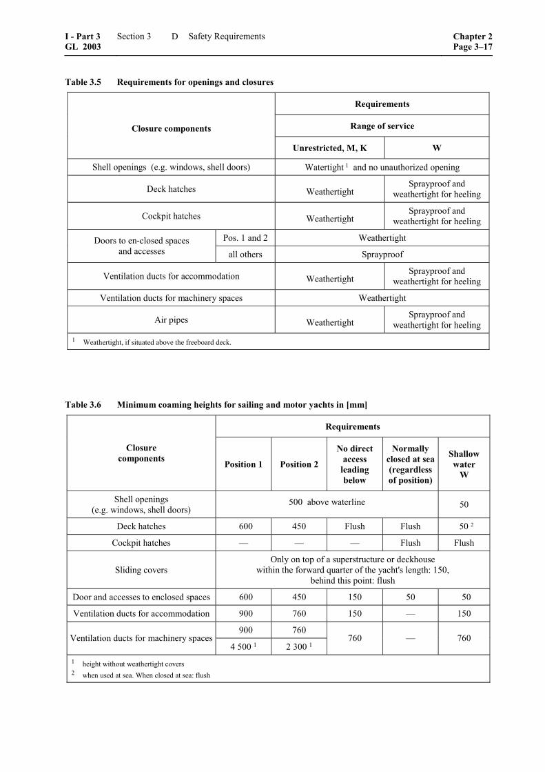
Table 3.5 Requirements for openings and closures
Requirements
Range of service Closure components
Unrestricted, M, K W
Shell openings (e.g. windows, shell doors) Watertight 1 and no unauthorized opening
Deck hatches Weathertight Sprayproof and
weathertight for heeling
Cockpit hatches Weathertight Sprayproof and
weathertight for heeling
Pos. 1 and 2 Weathertight Doors to en-closed spaces and accesses all others Sprayproof
Ventilation ducts for accommodation Weathertight Sprayproof and
weathertight for heeling
Ventilation ducts for machinery spaces Weathertight
Air pipes Weathertight Sprayproof and
weathertight for heeling 1 Weathertight, if situated above the freeboard deck.
Table 3.6 Minimum coaming heights for sailing and motor yachts in [mm]
Requirements
Closure components Position 1 Position 2
No direct access
leading below
Normally closed at sea (regardless of position)
Shallow water
W
Shell openings (e.g. windows, shell doors)
500 above waterline 50
Deck hatches 600 450 Flush Flush 50 2
Cockpit hatches –– –– –– Flush Flush
Sliding covers Only on top of a superstructure or deckhouse
within the forward quarter of the yacht's length: 150, behind this point: flush
Door and accesses to enclosed spaces 600 450 150 50 50
Ventilation ducts for accommodation 900 760 150 –– 150
900 760 Ventilation ducts for machinery spaces
4 500 1 2 300 1 760 –– 760
1 height without weathertight covers 2 when used at sea. When closed at sea: flush
I - Part 3 GL 2003
Section 3 Safety Requirements Chapter 2Page 3–17
D
3. Windows, skylights and side scuttles
3.1 Windows and side scuttles
3.1.1 Closure condition
In any case, windows opening into enclosed spaces shall be watertight and adequately dimensioned for the intended range of service.
Note
The respective ISO-Standards (e.g. DIN ISO 1751 and ISO 3903) are to be considered as guidance. Other types are to be submitted for approval.
3.1.2 Windows in the hull
Windows in the hull which can be opened must be kept closed when at sea. The bottom edge of win-dows in the hull shall be at least 500 mm above the flotation plane. Windows in the hull are not permitted in machinery spaces.
3.1.3 Deadlights
Deadlights are to be carried on board for all windows in the hull in accordance with the LLC 66 Regula-tions as amended or where required from stability point of view.
Windows and side scuttles in deckhouses on the freeboard deck forming the only protection of open-ings giving access to a space below, are in general to be provided with permanently attached deadlights.
Special constructions with equivalent safety stan-dards may be used on request and after special ex-amination/testing and with the consent of the compe-tent Flag State Administration.
3.1.4 Window panes
Window panes shall preferably be made of tough-ened, tempered safety glass ("ESG"), or laminated glass ("MSG"); polymethylmethacrylate ("PMMA") and polycarbonate ("PC") sheet material may also be used under special consideration.
Machinery space windows panes in the deckhouses must be of toughened/tempered safety glass, unless an external deadlight is provided, which can be oper-ated in an easy way.
Plastic panes shall be UV-stabilized, in addition scratch resistance is recommended.
3.1.5 Window framing
Panes of PMMA or PC sheet material are to be fixed by frames. They may also be bolted, provided the bolting is capable of resisting the stresses arising and guarantees lasting watertightness. The bearing width of the glass is to be 3 % of whichever is the shortest side of the pane, but at least 20 mm.
Designs offering equivalent safety may be permitted. The strength is to be proven by tests and/or calcula-tion.
Note
If bonding is used, it shall only be executed with materials approved by GL, by personnel certified by GL and considering the requirements of the GL Guideline II – Materials and Welding, Part 2 – Non-metallic Materials, Chapter 3 – Guidelines for Elas-tomeric Adhesives and Adhesive Joints.
3.1.6 Glass thickness
The window glass thickness has to be determined in accordance with the respective ISO and DIN stan-dards or with equivalent regulations.
3.2 Skylights
3.2.1 All skylights shall be of efficient weather-tight construction and shall be located on or as near to the centreline of the yacht as practicable. If they are of the opening type they shall be provided with effi-cient means whereby they can be secured in the closed position.
3.2.2 Skylights which are provided as a means of escape shall be operable from both sides. An escape skylight shall be readily identified and easy and safe to use, having due regard to its position and access to and from the skylight.
3.2.3 For glass and framing of skylights see 3.1.4, 3.1.5 and 3.1.6. A minimum of one portable cover for each size of glazed opening should be provided, which can be accessed rapidly and efficiently secured in the event of a breakage of the skylight.
3.2.4 Skylights shall not be fitted in way of the machinery space.
4. Cockpit
Especially for sailing yachts a cockpit may be pro-vided. Its lay-out has to consider the following crite-ria.
4.1 Structure
The cockpit floor plus longitudinal and transverse walls are to be considered as primary structural members, the scantlings of which shall be in accor-dance with the requirements of Section 2.
Cockpits shall be watertight to the inside of the yacht.
4.2 Closure condition
Regarding closures and coaming heights of hatches and doors of adjoining storage and living spaces, see 2. and 3.
Chapter 2 Page 3–18
Section 3 Safety Requirements I - Part 3GL 2003
D
4.3 Cockpit floor
The cockpit floor must be sufficiently high above the flotation plane so that water that has entered may be drained immediately through drain pipes or clearing ports under all foreseeable states of heel and trim of the yacht.
4.4 Drain pipes
4.4.1 Cross section
Each cockpit shall be provided with at least one drain pipe at each side. The total cross section f of the pipes on both sides shall be determined as follows:
2f 15 V [cm ]= ⋅
V = cockpit volume [m3], measured to top edge of cockpit coaming at its lowest point
Minimum total cross section for different ranges of service:
– unrestricted: 30,0 cm2
– M and K: 20,5 cm2
– W: 15,0 cm2
These cross section values are also required in the area of any strainers that may be present.
Cockpits extending all the way across the yacht must have clearing ports or drain pipe cross sections in accordance with 6.
4.4.2 Design details
Cockpit drain pipes shall be equal in strength to the surrounding hull and may only be replaced by hoses with special permission of GL. Valves in cockpit drain pipes must be kept permanently open.
4.4.3 Short hose sleeves
Short hose sleeves are permissible under the follow-ing conditions:
– The distance between sleeve and waterline shall be at least 100 mm.
– The sleeve shall still be above the waterline with the yacht heeled 15°.
– The hose used shall be in accordance with DIN 10022 or an equivalent standard.
– Two corrosion resistant clips are to be fitted at each end of the sleeve.
5. Deck drainage
5.1 Closure condition
Where bulwarks on exposed portions of freeboard and/or superstructure decks form wells, ample provi-sion is to be made for rapidly freeing the deck of water. Therefore an adequate number of freeing ports or drain pipes of adequate size shall be fitted.
5.2 Freeing ports
5.2.1 The minimum area of openings on one side of the yacht A is to be determined in accordance with the following formula:
A 0,07= ⋅
= length of bulwark [m]
max = 0,7 L
5.2.2 The opening area for each well in a super-structure deck shall not be less than 50 % of A.
If the bulwark is more than 1,2 m in average height, A is to be increased by 0,004 m2 per metre of length of well for each 0,1 m difference in height. If the bulwark is less than 0,9 m in average height, A may be decreased accordingly.
For yachts with no sheer A has to be increased by 50 %. Where the sheer is less than the standard, the percentage shall be obtained by linear interpolation.
5.2.3 Two thirds of the freeing port area required shall be provided in the half of the well nearest to the lowest point of the shear curve.
The lower edges of the freeing ports shall be as near to the deck as practicable.
All openings shall be protected by rails or bars spaced approximately 230 mm apart.
If shutters are fitted, ample clearance shall be pro-vided to prevent jamming.
Hinges shall have pins or bearings of non-corrodible material.
5.3 Scuppers
5.3.1 Scuppers sufficient in number and size to provide effective drainage of water are to be fitted in the weather deck and in the freeboard deck within weathertight closed superstructures and deckhouses. Decks within closed superstructures are to be drained to the bilge. Scuppers from superstructures and deck-houses which are not closed weathertight are to be led outside.
5.3.2 Scupper draining spaces below the design waterline are to be led to the bilges.
I - Part 3 GL 2003
Section 3 Safety Requirements Chapter 2Page 3–19
D
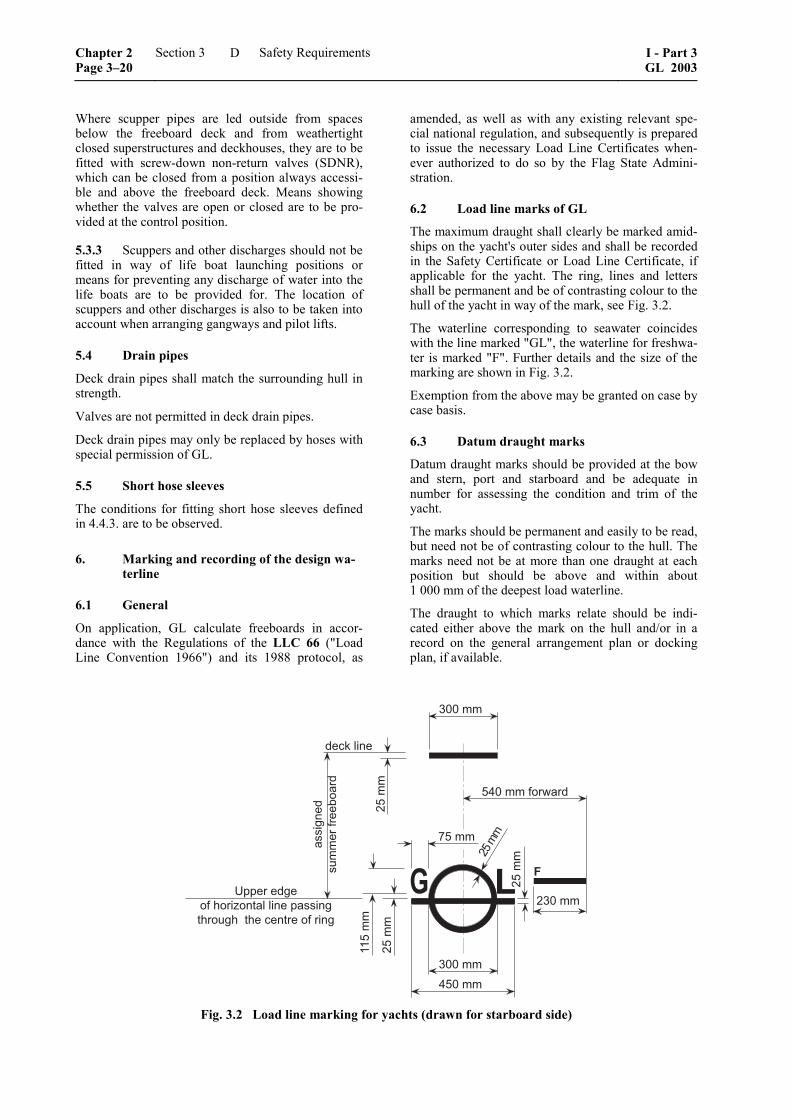
Where scupper pipes are led outside from spaces below the freeboard deck and from weathertight closed superstructures and deckhouses, they are to be fitted with screw-down non-return valves (SDNR), which can be closed from a position always accessi-ble and above the freeboard deck. Means showing whether the valves are open or closed are to be pro-vided at the control position.
5.3.3 Scuppers and other discharges should not be fitted in way of life boat launching positions or means for preventing any discharge of water into the life boats are to be provided for. The location of scuppers and other discharges is also to be taken into account when arranging gangways and pilot lifts.
5.4 Drain pipes
Deck drain pipes shall match the surrounding hull in strength.
Valves are not permitted in deck drain pipes.
Deck drain pipes may only be replaced by hoses with special permission of GL.
5.5 Short hose sleeves
The conditions for fitting short hose sleeves defined in 4.4.3. are to be observed.
6. Marking and recording of the design wa-terline
6.1 General
On application, GL calculate freeboards in accor-dance with the Regulations of the LLC 66 ("Load Line Convention 1966") and its 1988 protocol, as
amended, as well as with any existing relevant spe-cial national regulation, and subsequently is prepared to issue the necessary Load Line Certificates when-ever authorized to do so by the Flag State Admini-stration.
6.2 Load line marks of GL
The maximum draught shall clearly be marked amid-ships on the yacht's outer sides and shall be recorded in the Safety Certificate or Load Line Certificate, if applicable for the yacht. The ring, lines and letters shall be permanent and be of contrasting colour to the hull of the yacht in way of the mark, see Fig. 3.2.
The waterline corresponding to seawater coincides with the line marked "GL", the waterline for freshwa-ter is marked "F". Further details and the size of the marking are shown in Fig. 3.2.
Exemption from the above may be granted on case by case basis.
6.3 Datum draught marks
Datum draught marks should be provided at the bow and stern, port and starboard and be adequate in number for assessing the condition and trim of the yacht.
The marks should be permanent and easily to be read, but need not be of contrasting colour to the hull. The marks need not be at more than one draught at each position but should be above and within about 1 000 mm of the deepest load waterline.
The draught to which marks relate should be indi-cated either above the mark on the hull and/or in a record on the general arrangement plan or docking plan, if available.
�
�����������
����
�����
����
����������������������������������������������������������
����
���������
������
��������
�������������
����
������
�����
� �
������
������
Fig. 3.2 Load line marking for yachts (drawn for starboard side)
Chapter 2 Page 3–20
Section 3 Safety Requirements I - Part 3GL 2003
D
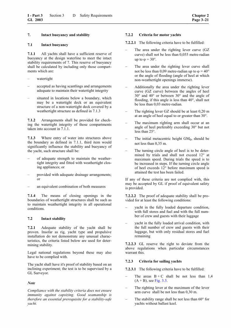
7. Intact buoyancy and stability
7.1 Intact buoyancy
7.1.1 All yachts shall have a sufficient reserve of buoyancy at the design waterline to meet the intact stability requirements of 7. This reserve of buoyancy shall be calculated by including only those compart-ments which are:
– watertight
– accepted as having scantlings and arrangements adequate to maintain their watertight integrity
– situated in locations below a boundary, which may be a watertight deck or an equivalent structure of a non-watertight deck covered by a weathertight structure as defined in 7.1.3
7.1.2 Arrangements shall be provided for check-ing the watertight integrity of those compartments taken into account in 7.1.1.
7.1.3 Where entry of water into structures above the boundary as defined in 7.1.1, third item would significantly influence the stability and buoyancy of the yacht, such structure shall be:
– of adequate strength to maintain the weather-tight integrity and fitted with weathertight clos-ing appliances; or
– provided with adequate drainage arrangements; or
– an equivalent combination of both measures
7.1.4 The means of closing openings in the boundaries of weathertight structures shall be such as to maintain weathertight integrity in all operational conditions.
7.2 Intact stability
7.2.1 Adequate stability of the yacht shall be proven. Insofar as rig, yacht type and propulsive installation do not demonstrate any unusual charac-teristics, the criteria listed below are used for deter-mining stability.
Legal national regulations beyond these may also have to be complied with.
The yacht shall have it's proof of stability based on an inclining experiment; the test is to be supervised by a GL Surveyor.
Note
Compliance with the stability criteria does not ensure immunity against capsizing. Good seamanship is therefore an essential prerequisite for a stability-safe yacht.
7.2.2 Criteria for motor yachts
7.2.2.1 The following criteria have to be fulfilled:
– The area under the righting lever curve (GZ curve) shall not be less than 0,055 metre-radian up to ϕ = 30°.
– The area under the righting lever curve shall not be less than 0,09 metre-radian up to ϕ = 40° or the angle of flooding (angle of heel at which non-weathertight openings immerse).
– Additionally the area under the righting lever curve (GZ curve) between the angles of heel 30° and 40° or between 30° and the angle of flooding, if this angle is less than 40°, shall not be less than 0,03 metre-radian.
– The righting lever GZ should be at least 0,20 m at an angle of heel equal to or greater than 30°.
– The maximum righting arm shall occur at an angle of heel preferably exceeding 30° but not less than 25°.
– The initial metacentric height GM0, should be not less than 0,35 m.
– The turning circle angle of heel is to be deter-mined by trials and shall not exceed 12° at maximum speed. During trials the speed is to be increased in steps. If the turning circle angle of heel exceeds 12° before maximum speed is attained the test has been failed.
If any of these criteria are not complied with, this may be accepted by GL if proof of equivalent safety is provided.
7.2.2.2 The proof of adequate stability shall be pro-vided for at least the following conditions:
– yacht in the fully loaded departure condition, with full stores and fuel and with the full num-ber of crew and guests with their luggage
– yacht in the fully loaded arrival condition, with the full number of crew and guests with their luggage, but with only residual stores and fuel remaining
7.2.2.3 GL reserve the right to deviate from the above regulations when particular circumstances warrant this.
7.2.3 Criteria for sailing yachts
7.2.3.1 The following criteria have to be fulfilled:
– The areas B + C shall be not less than 1,4 (A + B), see Fig. 3.3.
– The righting lever at the maximum of the lever arm curve shall be not less than 0,30 m.
– The stability range shall be not less than 60° for yachts without ballast keel.
I - Part 3 GL 2003
Section 3 Safety Requirements Chapter 2Page 3–21
D

– The stability range shall be not less than 90° for yachts with ballast keel.
– The initial metacentric height GM0 shall not be less than 0,60 m.
– The static angle of heel under sail shall not exceed 20°, but in any way shall not be more than the angle of deck immersion.
��
�
�
�
���
Fig. 3.3 Lever arm curve
hKW = curve of heeling levers due to lateral wind pressure
7.2.3.2 If any of these criteria are not complied with, this may be accepted by GL, if proof of equiva-lent safety is provided.
For multi hull sailing craft, stability ranges smaller than 60° may be permitted.
7.2.3.3 The proof of adequate stability shall be pro-vided for the yacht at least under the following condi-tions:
– all sails set
– half the sail area
– storm sails
– sails struck
In each case the permissible wind speed or force shall be determined at which the limit of stability set by the criteria is reached. With the sails struck, a lateral wind pressure equivalent to Beaufort-Force 12 (32,7 – 36,9 m/s = 63,6 – 71,7 kn) must be tolerable.
7.2.4 Ice Class
The effect of icing has to be considered in the stabil-ity calculation if a Class Notation for ice has been requested.
8. Subdivision and damage stability
8.1 Bulkheads
8.1.1 At least the following watertight bulkheads are to be fitted in all yachts:
– one collision bulkhead
– one afterpeak bulkhead
– one bulkhead at each end of the machinery space
8.1.2 The distance [m] of the collision bulkhead from the forward perpendicular is to be between 0,035 L and 0,05 L + 3 m.
8.1.3 Where compliance with 8.1.2 seems imprac-tical for the particular design of the yacht, the re-quirement may be substituted by proof of survivabil-ity of simultaneous damage to all compartments be-tween 0,035 L and the forward end of the yacht ac-cording to the criteria defined in 8.3.3.
8.2 Double bottom
8.2.1 At least for yachts with a length L exceeding 48 m a double bottom should be fitted extending from the fore peak bulkhead to the after peak bulk-head, as far as practicable and compatible with the design and proper operation of the ship. In any case, a double bottom must be fitted in areas prescribed in Regulation II-1/12 of SOLAS 74.
8.2.2 The double bottom has to protect the yacht's bottom up to the turn of the bilge. For this purpose, the intersecting line of the outer edge of the margin plate with the shell plating is not to be lower at any part than a horizontal plane, passing through the point of intersection with the frame line amidships of a transverse diagonal line inclined 25 degrees to the baseline and cutting the base line at B/2 from the centreline of the yacht (see Fig. 3.4).
�����������
������ � �
���
�
!"�
���������������������������#��������������������$
%&�����#��������������������$
Fig. 3.4 Double bottom with drain sumps location
8.2.3 The double bottom need not be fitted in way of deep tanks, provided that the efficiency of the watertight subdivision is not impaired by such an arrangement.
8.2.4 The bottoms of drain sumps are to be situ-ated at a distance of at least 460 mm from the base line. Only above the horizontal plane determined from 8.2.2, the bottoms of drain wells may be led to the shell plating. Exemptions for the depth of drain
Chapter 2 Page 3–22
Section 3 Safety Requirements I - Part 3GL 2003
D

wells may also be granted in shaft tunnels and pipe tunnels.
8.3 Damage stability
8.3.1 General
For yachts with a length L exceeding 48 m a damage stability investigation is required.
For yachts with a length L between 48 m and 85 m sufficient damage stability has to be shown by calcu-lating one compartment damages. For yachts with a length L exceeding 85 m a calculation of two com-partment damages is required additionally.
8.3.2 Damage stability calculation
8.3.2.1 General
Compliance with the damage stability criteria has to be shown in all permitted conditions of loading to withstand all stages of flooding of the main com-partments.
8.3.2.2 Assumptions
The damage stability calculation shall be based on the following assumptions:
– The assumed extent of damage shall be as fol-lows:
– longitudinal extent: 3 m plus 3 % of the length L of the yacht or 11 m, whichever is less
– transverse extent (to be measured inboard from the ship's side, at right angles to the centre line at the level of the deepest subdi-vision load line): a distance of one fifth of the breadth of the yacht
– vertical extent: from the base line upwards without limit
– If any damage of lesser extent than that indicated above would result in a more se-vere condition regarding heel or loss of metacentric height, such damage shall be as-sumed in the calculations.
– For damage stability calculations, the perme-ability for each space or part of a space shall be used as set out in Table 3.7.
– Direct calculation of permeability shall be used where a more onerous condition results, and may be used where a less onerous condition re-sults, if compared with the second item.
Table 3.7 Values of permeability
Definition of spaces Permeability [%]
Control stations, accommodation rooms, kitchens, pantries 95
Machinery and ventilation rooms 85
Storage rooms, refrigerating rooms 60
Garages for automobiles and other craft 90
Tanks, bunkers, cells 0 or 95 1
Void spaces 95 1 whichever results in more severe requirements
8.3.3 Stability criteria
8.3.3.1 The stability required in the final condition after damage, and after equalization where provided, shall be determined as follows:
– The positive residual righting lever curve shall have a minimum range of 15° beyond the angle of equilibrium.
– The area under the righting lever curve shall be at least 0,015 metre-radians, measured from the angle of equilibrium to the angle at which pro-gressive flooding occurs.
– A residual righting lever is to be obtained within the range of the positive stability of at least 0,1 m.
8.3.3.2 Unsymmetrical flooding has to be kept to a minimum. Efficient cross flooding arrangements should correct large angles of heel preferably in a self acting way. If the cross flooding system is not self-acting the required time of equalization shall not exceed 15 minutes. Sufficient time of equalization has to be demonstrated by calculation.
8.3.4 Final condition of yacht
The final conditions of the yacht after damage and, in case of unsymmetrical flooding, after equalization measures have been taken, shall be as follows:
– In case of symmetrical flooding there shall be a positive residual metacentric height of at least 50 mm as calculated by the constant displace-ment method.
– In case of unsymmetrical flooding, the angle of heel for one-compartment flooding shall not exceed 7°, for the simultaneous flooding of two or more adjacent compartments, a heel of 12° may be permitted by GL.
I - Part 3 GL 2003
Section 3 Safety Requirements Chapter 2Page 3–23
D

– In no case shall the final waterline be less than 300 mm below the level of any opening through which further flooding could take place.
8.3.5 Use of low density foam
Use of low density foam or other media to provide buoyancy in void spaces may be permitted, provided that satisfactory evidence is provided that any such proposed medium is the most suitable alternative and is:
– of closed cell form, or otherwise impervious to water absorption
– structurally stable under service conditions
– chemically inert in relation to structural materi-als with which it is in contact or to other sub-stances with which the medium is likely to be in contact
– properly secured in place and easily removable for inspection of the void spaces
8.4 Damage control plan
8.4.1 There shall be permanently exhibited or readily available on the navigating bridge, for the guidance of the officer in charge of the yacht, a plan showing clearly:
– for each deck and compartment the boundaries of the watertight compartments, the openings therein with the means of closure and position of any controls thereof
– for doors, a description of degree of tightness, operating mode, normal position, operating cir-cumstances (opened while at sea, not normally used while at sea, not used while at sea)
– arrangements for the correction of any list due to flooding
8.4.2 General precautions shall consist of a listing of equipment, conditions and operational procedures, considered to be necessary to maintain watertight integrity under normal yacht operations.
8.4.3 Specific precautions shall consist of a listing of elements (i.e. closures, securing of equip-ment/loads, sounding of alarm, etc.) considered to be vital to the survival of the yacht and its crew.
9. Inclining and stability information
9.1 Every yacht on completion of build shall undergo an inclination test and the elements of its stability determined. If an accurate inclining is not practical, the lightship displacement and centre of gravity should be determined by a lightweight survey and accurate calculation.
9.2 The master shall be supplied by the owner with reliable information relating to the stability of the yacht in accordance with the provisions of D. The information relating to stability shall, before issue to the master, be submitted to GL for approval and shall incorporate such additions and amendments as GL may require in any particular case.
9.3 Where any alterations are made to a yacht so as to materially affect the stability information sup-plied to the master, amended stability information should be provided. If necessary, the yacht shall be re-inclined.
9.4 A report of each inclination test carried out in accordance with D. or of each calculation of the lightship condition particulars shall be submitted to GL for approval. The approved report shall be placed on board of the yacht in the custody of the mas-ter/owner and should incorporate such additions and amendments as GL may require in any particular case.
E. Requirements for Hydraulically-Operated Equipment
1. General
1.1 Scope
The requirements contained in E. apply to hydrauli-cally-operated systems used, for example, to move deck/hatch covers, closing appliances in the yacht’s shell and at bulkheads, hoists and stabilizers. The requirements are to be applied in analogous manner to the yacht's other hydraulic systems.
1.2 Documents for approval
The diagram of the hydraulic system together with drawings of the cylinders containing all the data necessary for assessing and checking the system, e.g. operating data, descriptions, materials used, etc. are to be submitted in triplicate for approval.
1.3 Dimensional design
For the design of pressure vessels and for dimensions of pipes and hose assemblies see references defined in Section 1, C.
1.4 Materials
1.4.1 Approved materials
1.4.1.1 Components fulfilling a major function in the power transmission system shall normally be made of steel or cast steel in accordance with the GL Rules II – Materials and Welding, Part 1 – Metallic
Chapter 2 Page 3–24
Section 3 Safety Requirements I - Part 3GL 2003
E
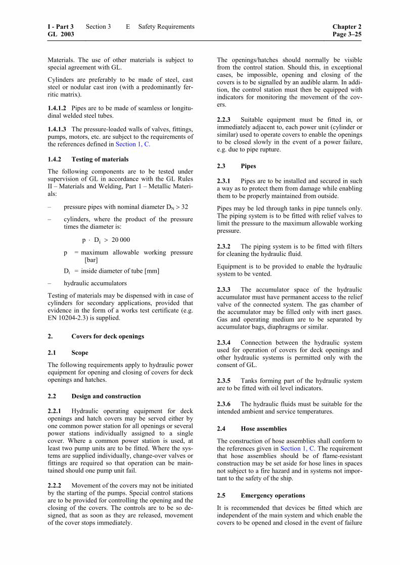
Materials. The use of other materials is subject to special agreement with GL.
Cylinders are preferably to be made of steel, cast steel or nodular cast iron (with a predominantly fer-ritic matrix).
1.4.1.2 Pipes are to be made of seamless or longitu-dinal welded steel tubes.
1.4.1.3 The pressure-loaded walls of valves, fittings, pumps, motors, etc. are subject to the requirements of the references defined in Section 1, C.
1.4.2 Testing of materials
The following components are to be tested under supervision of GL in accordance with the GL Rules II – Materials and Welding, Part 1 – Metallic Materi-als:
– pressure pipes with nominal diameter DN > 32
– cylinders, where the product of the pressure times the diameter is:
ip D 20 000⋅ >
p = maximum allowable working pressure [bar]
Di = inside diameter of tube [mm]
– hydraulic accumulators
Testing of materials may be dispensed with in case of cylinders for secondary applications, provided that evidence in the form of a works test certificate (e.g. EN 10204-2.3) is supplied.
2. Covers for deck openings
2.1 Scope
The following requirements apply to hydraulic power equipment for opening and closing of covers for deck openings and hatches.
2.2 Design and construction
2.2.1 Hydraulic operating equipment for deck openings and hatch covers may be served either by one common power station for all openings or several power stations individually assigned to a single cover. Where a common power station is used, at least two pump units are to be fitted. Where the sys-tems are supplied individually, change-over valves or fittings are required so that operation can be main-tained should one pump unit fail.
2.2.2 Movement of the covers may not be initiated by the starting of the pumps. Special control stations are to be provided for controlling the opening and the closing of the covers. The controls are to be so de-signed, that as soon as they are released, movement of the cover stops immediately.
The openings/hatches should normally be visible from the control station. Should this, in exceptional cases, be impossible, opening and closing of the covers is to be signalled by an audible alarm. In addi-tion, the control station must then be equipped with indicators for monitoring the movement of the cov-ers.
2.2.3 Suitable equipment must be fitted in, or immediately adjacent to, each power unit (cylinder or similar) used to operate covers to enable the openings to be closed slowly in the event of a power failure, e.g. due to pipe rupture.
2.3 Pipes
2.3.1 Pipes are to be installed and secured in such a way as to protect them from damage while enabling them to be properly maintained from outside.
Pipes may be led through tanks in pipe tunnels only. The piping system is to be fitted with relief valves to limit the pressure to the maximum allowable working pressure.
2.3.2 The piping system is to be fitted with filters for cleaning the hydraulic fluid.
Equipment is to be provided to enable the hydraulic system to be vented.
2.3.3 The accumulator space of the hydraulic accumulator must have permanent access to the relief valve of the connected system. The gas chamber of the accumulator may be filled only with inert gases. Gas and operating medium are to be separated by accumulator bags, diaphragms or similar.
2.3.4 Connection between the hydraulic system used for operation of covers for deck openings and other hydraulic systems is permitted only with the consent of GL.
2.3.5 Tanks forming part of the hydraulic system are to be fitted with oil level indicators.
2.3.6 The hydraulic fluids must be suitable for the intended ambient and service temperatures.
2.4 Hose assemblies
The construction of hose assemblies shall conform to the references given in Section 1, C. The requirement that hose assemblies should be of flame-resistant construction may be set aside for hose lines in spaces not subject to a fire hazard and in systems not impor-tant to the safety of the ship.
2.5 Emergency operations
It is recommended that devices be fitted which are independent of the main system and which enable the covers to be opened and closed in the event of failure
I - Part 3 GL 2003
Section 3 Safety Requirements Chapter 2Page 3–25
E
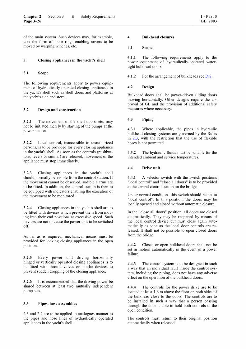
of the main system. Such devices may, for example, take the form of loose rings enabling covers to be moved by warping winches, etc.
3. Closing appliances in the yacht's shell
3.1 Scope
The following requirements apply to power equip-ment of hydraulically operated closing appliances in the yacht's shell such as shell doors and platforms at the yacht's side and stern.
3.2 Design and construction
3.2.1 The movement of the shell doors, etc. may not be initiated merely by starting of the pumps at the power station.
3.2.2 Local control, inaccessible to unauthorized persons, is to be provided for every closing appliance in the yacht's shell. As soon as the controls (pushbut-tons, levers or similar) are released, movement of the appliance must stop immediately.
3.2.3 Closing appliances in the yacht's shell should normally be visible from the control station. If the movement cannot be observed, audible alarms are to be fitted. In addition, the control station is then to be equipped with indicators enabling the execution of the movement to be monitored.
3.2.4 Closing appliances in the yacht's shell are to be fitted with devices which prevent them from mov-ing into their end positions at excessive speed. Such devices are not to cause the power unit to be switched off.
As far as is required, mechanical means must be provided for locking closing appliances in the open position.
3.2.5 Every power unit driving horizontally hinged or vertically operated closing appliances is to be fitted with throttle valves or similar devices to prevent sudden dropping of the closing appliance.
3.2.6 It is recommended that the driving power be shared between at least two mutually independent pump sets.
3.3 Pipes, hose assemblies
2.3 and 2.4 are to be applied in analogues manner to the pipes and hose lines of hydraulically operated appliances in the yacht's shell.
4. Bulkhead closures
4.1 Scope
4.1.1 The following requirements apply to the power equipment of hydraulically-operated water-tight bulkhead doors.
4.1.2 For the arrangement of bulkheads see D.8.
4.2 Design
Bulkhead doors shall be power-driven sliding doors moving horizontally. Other designs require the ap-proval of GL and the provision of additional safety measures where necessary.
4.3 Piping
4.3.1 Where applicable, the pipes in hydraulic bulkhead closing systems are governed by the Rules in 2.3, with the restriction that the use of flexible hoses is not permitted.
4.3.2 The hydraulic fluids must be suitable for the intended ambient and service temperatures.
4.4 Drive unit
4.4.1 A selector switch with the switch positions "local control" and "close all doors" is to be provided at the central control station on the bridge.
Under normal conditions this switch should be set to "local control". In this position, the doors may be locally opened and closed without automatic closure.
In the "close all doors" position, all doors are closed automatically. They may be reopened by means of the local control device but must close again auto-matically as soon as the local door controls are re-leased. It shall not be possible to open closed doors from the bridge.
4.4.2 Closed or open bulkhead doors shall not be set in motion automatically in the event of a power failure.
4.4.3 The control system is to be designed in such a way that an individual fault inside the control sys-tem, including the piping, does not have any adverse effect on the operation of the bulkhead doors.
4.4.4 The controls for the power drive are to be located at least 1,6 m above the floor on both sides of the bulkhead close to the doors. The controls are to be installed in such a way that a person passing through the door is able to hold both controls in the open condition.
The controls must return to their original position automatically when released.
Chapter 2 Page 3–26
Section 3 Safety Requirements I - Part 3GL 2003
E
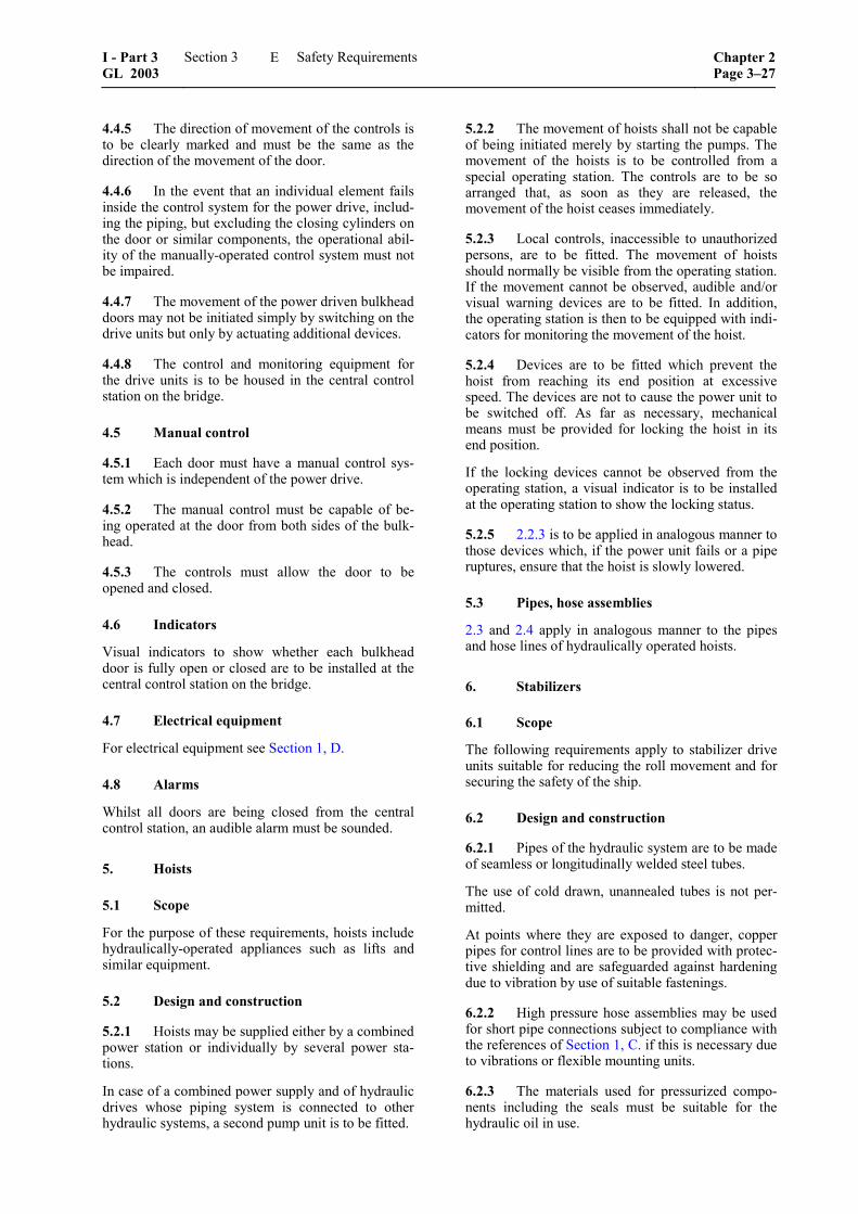
4.4.5 The direction of movement of the controls is to be clearly marked and must be the same as the direction of the movement of the door.
4.4.6 In the event that an individual element fails inside the control system for the power drive, includ-ing the piping, but excluding the closing cylinders on the door or similar components, the operational abil-ity of the manually-operated control system must not be impaired.
4.4.7 The movement of the power driven bulkhead doors may not be initiated simply by switching on the drive units but only by actuating additional devices.
4.4.8 The control and monitoring equipment for the drive units is to be housed in the central control station on the bridge.
4.5 Manual control
4.5.1 Each door must have a manual control sys-tem which is independent of the power drive.
4.5.2 The manual control must be capable of be-ing operated at the door from both sides of the bulk-head.
4.5.3 The controls must allow the door to be opened and closed.
4.6 Indicators
Visual indicators to show whether each bulkhead door is fully open or closed are to be installed at the central control station on the bridge.
4.7 Electrical equipment
For electrical equipment see Section 1, D.
4.8 Alarms
Whilst all doors are being closed from the central control station, an audible alarm must be sounded.
5. Hoists
5.1 Scope
For the purpose of these requirements, hoists include hydraulically-operated appliances such as lifts and similar equipment.
5.2 Design and construction
5.2.1 Hoists may be supplied either by a combined power station or individually by several power sta-tions.
In case of a combined power supply and of hydraulic drives whose piping system is connected to other hydraulic systems, a second pump unit is to be fitted.
5.2.2 The movement of hoists shall not be capable of being initiated merely by starting the pumps. The movement of the hoists is to be controlled from a special operating station. The controls are to be so arranged that, as soon as they are released, the movement of the hoist ceases immediately.
5.2.3 Local controls, inaccessible to unauthorized persons, are to be fitted. The movement of hoists should normally be visible from the operating station. If the movement cannot be observed, audible and/or visual warning devices are to be fitted. In addition, the operating station is then to be equipped with indi-cators for monitoring the movement of the hoist.
5.2.4 Devices are to be fitted which prevent the hoist from reaching its end position at excessive speed. The devices are not to cause the power unit to be switched off. As far as necessary, mechanical means must be provided for locking the hoist in its end position.
If the locking devices cannot be observed from the operating station, a visual indicator is to be installed at the operating station to show the locking status.
5.2.5 2.2.3 is to be applied in analogous manner to those devices which, if the power unit fails or a pipe ruptures, ensure that the hoist is slowly lowered.
5.3 Pipes, hose assemblies
2.3 and 2.4 apply in analogous manner to the pipes and hose lines of hydraulically operated hoists.
6. Stabilizers
6.1 Scope
The following requirements apply to stabilizer drive units suitable for reducing the roll movement and for securing the safety of the ship.
6.2 Design and construction
6.2.1 Pipes of the hydraulic system are to be made of seamless or longitudinally welded steel tubes.
The use of cold drawn, unannealed tubes is not per-mitted.
At points where they are exposed to danger, copper pipes for control lines are to be provided with protec-tive shielding and are safeguarded against hardening due to vibration by use of suitable fastenings.
6.2.2 High pressure hose assemblies may be used for short pipe connections subject to compliance with the references of Section 1, C. if this is necessary due to vibrations or flexible mounting units.
6.2.3 The materials used for pressurized compo-nents including the seals must be suitable for the hydraulic oil in use.
I - Part 3 GL 2003
Section 3 Safety Requirements Chapter 2Page 3–27
E
6.2.4 The sealing arrangement at the penetration of the fin shaft through the yacht's shell has to be submitted for approval.
6.2.5 For retractable stabilizer fins the actual posi-tion has to be indicated at the bridge.
7. Tests and trials
7.1 Tests in the manufacturer's factory
7.1.1 Testing of power units
The power units are required to undergo testing on a test bed. Factory test certificates for this testing are to be presented at the final inspection of the hydraulic system.
7.1.2 Pressure and tightness tests
Pressure components are to undergo a pressure test.
The test pressure
[ ]cp 1,5 p bar= ⋅
p = the maximum allowable working pressure [bar] or the pressure at which the relieve valves open. However, for working pres-sures above 200 bar the test pressure need not exceed p + 100 bar.
For pressure testing of pipes their valves and fittings, see references in Section 1, C.
Tightness tests are to be performed on components to which this is appropriate at the discretion of the GL Surveyor.
7.2 Shipboard trials
7.2.1 After installation on board, the equipment is to undergo an operational test.
7.2.2 The operational test of watertight doors has to include the emergency operating system and de-termination of closing time.
7.2.3 The operational efficiency of the stabilizer equipment is to be demonstrated during the sea trials.
F. Requirements for Helicopter Facilities
1. General
1.1 Scope
1.1.1 The following describes the requirements for the arrangement and the structures of helicopter land-ing deck, the arrangement of aviation fuel tanks and the necessary safety measures including fire extin-guishing.
1.1.2 It is assumed that only one helicopter will be operated at a time. The landing deck is to be dimen-sioned for the largest helicopter type expected for helicopter operation. The characteristics of this heli-copter type have to be defined clearly in the docu-ments submitted for approval. It is assumed that the helicopter is parking on the open landing deck being safely lashed to the deck.
1.2 Hangar
If a helicopter hangar is provided, the additional requirements have to be defined case by case on the basis of other GL Rules.
1.3 Operation manual
Each helicopter facility shall have an operation man-ual, including a description and a checklist of safety precautions, procedures and equipment requirements.
2. Arrangement of helicopter landing decks
2.1 Positioning of the landing deck
A helicopter landing deck shall be situated on an upper deck. If the helicopter deck is situated at the stern of the yacht with superstructures/deckhouses beforehand it is recommended that the angle of pos-sible approaches should be at least 90° at each side of the yacht’s longitudinal axis.
A location of permanently occupied spaces, like accommodation, messes, service spaces under the helicopter deck shall be avoided because of safety reasons. If this is not possible, then the landing deck has to be designed completely as a crash zone, see 3.2, load case LC 3.
2.2 Size of a landing deck
In establishing a landing area it is essential to ensure a safe correlation between: – the sizes of helicopters expected to use the
landing deck – the dimensions of the aiming circle, clear zone
and manoeuvring zone and the permitted height of obstructions in these zones, see Fig. 3.5
The following three zones can be defined for a land-ing area:
– Aiming circle/touch down zone: The aiming circle is an area concentric to the
centre of the clear zone and has a diameter half that of the clear zone itself. The circle shall ac-commodate with safety the landing gear of heli-copters for which it is intended and shall there-fore be completely obstruction free. If this is not possible, obstructions not higher than 0,1 m may be permissible.
Chapter 2 Page 3–28
Section 3 Safety Requirements I - Part 3GL 2003
F
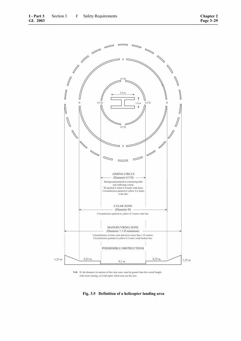
��������� �������� �
��������������������������������� !����������������
"���#$���%���� ��������& '� ���������
�����������������������(����������)���������*���& !+������, ��������������������������������� !������������-��.�������
���� /��*��������������������,������*��������(���/���,��-��0��������*����*���)���������0�*/���*������,�������0/������*�����������*��*������,���*������
' 1��
& 2��
� +�
� +�
� +� � +�
��"��%�������� ��������� +� �
3��.0�����������������������,���0����.���4���������0�������
565�������������*����� 7����������������, ��������������������������������� !������
���������
&/!+�� �/!+���/&�� &/!+���/!+��
8��"�99�3���39:�#�:��9
Fig. 3.5 Definition of a helicopter landing area
I - Part 3 GL 2003
Section 3 Safety Requirements Chapter 2Page 3–29
F

– Clear zone:
The clear zone shall be as large as possible recognising that its diameter D must be greater than the overall length with rotors turning, of a helicopter planned to use the landing area. There shall be no obstacles in the clear zone higher than 0,25 m.
– Manoeuvring zone:
The manoeuvring zone of the landing area extends the area in which the helicopter may manoeuvre with safety by enlarging, to a di-ameter of at least 1,3 D, the area over which the rotors of the helicopter may overhang without danger from high obstructions. If it is impossi-ble to remove all obstacles from the manoeu-vring zone, a graduated increase in permitted height of obstructions is defined in Fig. 3.5.
Note
For the convenience of the users of these Rules refer-ence is made to the "Guide to Helicopter/Ship Opera-tions" published by the International Chamber of Shipping (ICS).
3. Landing deck structures
3.1 Design loads
The following design load cases (LC) are to be con-sidered:
3.1.1 LC 1
helicopter lashed on deck, with the following vertical forces acting simultaneously:
– wheel and/or skid force P acting at the points resulting from the lashing position and distribu-tion of the wheels and/or supports according to helicopter construction.
[ ]vP 0,5 G (1 a ) kN= ⋅ +
�
G = maximum permissible take-off weight [kN]
P = evenly distributed force over the contact area f = 30 × 30 cm for single wheel or according to data supplied by helicopter manufacturers; for dual wheels or skids to be determined individually in accor-dance with given dimensions.
e = wheel or skid distance according to heli-copter types to be expected
av = F ⋅ m
F = 0v0,11
L
m = ( )0 0xm 5 m 1− −L
for x0 0,2≤ ≤L
= 1 for x0, 2 0,7≤ ≤L
= 0m 1 x1 0,70,3
+ ⎛ ⎞+ −⎜ ⎟⎝ ⎠L
for x0,7 1,0< ≤L
m0 = 1,5 + F
v0 = see Section 2, A.6.5
– force due to weight of helicopter deck Me as follows:
[ ]e vM (1 a ) kN+
– load p = 2,0 kN/m2 evenly distributed over the entire landing deck
3.1.2 LC 2
helicopter lashed on deck, with the following hori-zontal and vertical forces acting simultaneously:
– forces acting horizontally:
[ ]eH 0,6 (G M ) W kN= + +
W = wind load, taking into account the lashed helicopter;
wind velocity vw = 50 m/s
– forces acting vertically:
[ ]eV G M kN= +
3.1.3 LC 3
normal landing impact, with the following forces acting simultaneously:
– wheel and/or skid load P at two points simulta-neously, at an arbitrary (most unfavourable) point of the helicopter deck (landing zone + safety zone)
[ ]P 0,75 G kN=
– load p = 0,5 kN/m² evenly distributed
(for taking into account snow or other envi-ronmental loads)
– weight of the helicopter deck
Chapter 2 Page 3–30
Section 3 Safety Requirements I - Part 3GL 2003
F
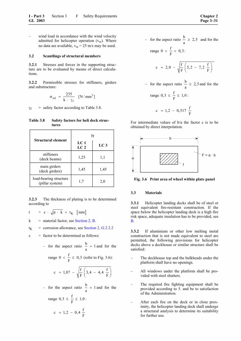
– wind load in accordance with the wind velocity admitted for helicopter operation (vw). Where no data are available, vw = 25 m/s may be used.
3.2 Scantlings of structural members
3.2.1 Stresses and forces in the supporting struc-ture are to be evaluated by means of direct calcula-tions.
3.2.2 Permissible stresses for stiffeners, girders and substructure:
2zul
f
235 [N / mm ]k
σ =⋅ γ
γf = safety factor according to Table 3.8.
Table 3.8 Safety factors for heli deck struc-tures
γf Structural element
LC 1 LC 2 LC 3
stiffeners (deck beams) 1,25 1,1
main girders (deck girders) 1,45 1,45
load-bearing structure (pillar system) 1,7 2,0
3.2.3 The thickness of plating is to be determined according to
t = [ ]Kc p k t mm⋅ ⋅ +
k = material factor, see Section 2, B.
tK = corrosion allowance, see Section 2, G.2.2.2
c = factor to be determined as follows:
– for the aspect ratio b 1a
= and for the
range f0 0,3F
< ≤ (refer to Fig. 3.6):
f fc 1,87 3,4 4,4F F
⎛ ⎞= − −⎜ ⎟⎝ ⎠
– for the aspect ratio b 1a
= and for the
range f0,3 1,0F
≤ ≤ :
fc 1,2 0, 4F
= −
– for the aspect ratio b 2,5a
≥ and for the
range f0 0,3F
< < :
f fc 2,0 5, 2 7, 2F F
⎛ ⎞= − −⎜ ⎟⎝ ⎠
– for the aspect ratio b 2,5a
≥ and for the
range f0,3 1,0F
≤ ≤ :
fc 1,2 0,517F
= −
For intermediate values of b/a the factor c is to be obtained by direct interpolation.
�
�
�
!�"������
Fig. 3.6 Print area of wheel within plate panel
3.3 Materials
3.3.1 Helicopter landing decks shall be of steel or steel equivalent fire-resistant construction. If the space below the helicopter landing deck is a high fire risk space, adequate insulation has to be provided, see B.
3.3.2 If aluminium or other low melting metal construction that is not made equivalent to steel are permitted, the following provisions for helicopter decks above a deckhouse or similar structure shall be satisfied:
– The deckhouse top and the bulkheads under the platform shall have no openings.
– All windows under the platform shall be pro-vided with steel shutters.
– The required fire fighting equipment shall be provided according to 5. and be to satisfaction of the Administration.
– After each fire on the deck or in close prox-imity, the helicopter landing deck shall undergo a structural analysis to determine its suitability for further use.
I - Part 3 GL 2003
Section 3 Safety Requirements Chapter 2Page 3–31
F
4. Landing deck equipment
4.1 Landing deck sheathing
The landing deck sheathing has to comply with the following requirements:
– resistant against increased mechanical impact at starting and landing procedure
– resistant against aircraft fuel, hydraulic and lubricating oils
– resistant against dry fire extinguishing powder and foams
– resistant against defrosting expedient and salt
– friction coefficient μ = 0,6 at minimum
4.2 Helicopter fastenings
In the parking zone means have to be provided for lashing of the helicopter. It is recommended to pro-vide one lashing point for about 2 m2 of the landing deck. The lashing points have to be flush with the deck.
4.3 Personnel safety measures
4.3.1 Two means of escape have to be provided from the landing deck. They shall be situated at the maximum possible distance from each other.
4.3.2 A collapsible railing has to be provided at the perimeter of the landing deck.
The railing shall follow the requirements for guard-rails according to A.2. The design shall be based on an outreach of 1,5 m at the folded down position, a mesh size of about 80 mm and a design load of at least 2,0 kN/m2.
5. Fire extinguishing systems
5.1 In close proximity to the helicopter landing deck there shall be provided and stored near the means of access to that deck:
5.1.1 At least two dry powder extinguishers hav-ing a total capacity of not less than 45 kg;
5.1.2 CO2-extinguishers of a total capacity of not less than 18 kg or equivalent;
5.1.3 A fixed low expansion foam system with monitors or foam making branch pipes capable of delivering foam to all parts of the helideck in all weather conditions in which helicopters can operate. The system shall be capable of delivering a discharge rate as required in Table 3.9 for at least five minutes.
Table 3.9 Discharge rate of foam solution
Helicopter category
Overall length of helicopter
l [m]
Discharge rate of
foam solution [l/min]
H1 l < 15 250
H2 15 ≤ l < 24 500
The foam agent shall meet the performance standards of ICAO 24 and be suitable for use with salt water.
5.1.4 At least two nozzles of dual-purpose type and hoses sufficient to reach any part of the helideck.
5.1.5 Two firemen's outfits in addition to those required by SOLAS or national regulations.
5.1.6 At least the following equipment, stored in a manner that provides for immediate use and protec-tion from the elements:
– adjustable wrench
– blanket, fire resistant
– cutters bolt 600 mm
– hook, grab or salving
– hacksaw, heavy duty complete with 6 spare blades
– ladder
– life line 5 mm diameter × 15 m in length
– pliers, side cutting
– set of assorted screwdrivers
– harness knife complete with sheat
5.2 Drainage of the helicopter landing deck
Drainage facilities in way of helicopter landing decks shall be constructed of flame proof material/steel and lead directly overboard independent of any other system and designed so that drainage does not fall on to any part of the yacht.
6. Aviation fuel arrangement
6.1 General
The following requirements apply to aviation fuel with a flash point above or below 60 °C.
6.2 Storage
6.2.1 General
6.2.1.1 For the storage of aviation fuel the general safety measures for fuel tanks are to be applied analogously, see Section 1, C.
Chapter 2 Page 3–32
Section 3 Safety Requirements I - Part 3GL 2003
F
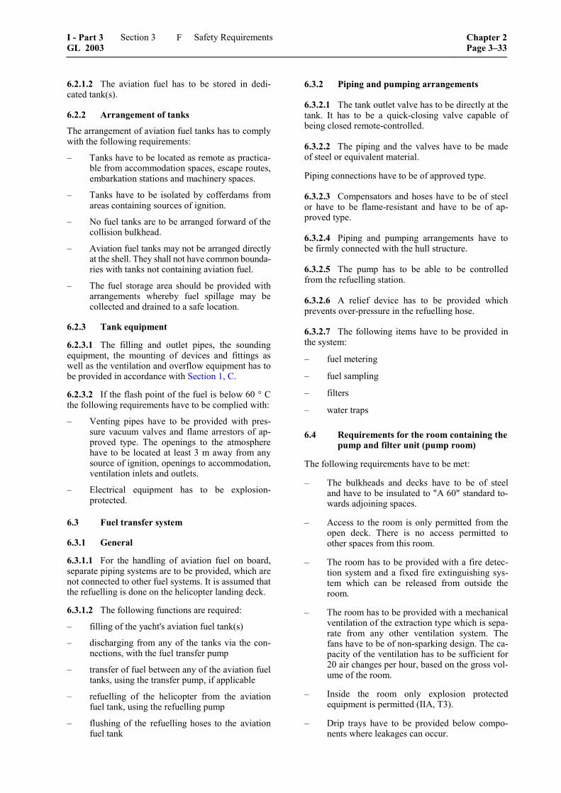
6.2.1.2 The aviation fuel has to be stored in dedi-cated tank(s).
6.2.2 Arrangement of tanks
The arrangement of aviation fuel tanks has to comply with the following requirements:
– Tanks have to be located as remote as practica-ble from accommodation spaces, escape routes, embarkation stations and machinery spaces.
– Tanks have to be isolated by cofferdams from areas containing sources of ignition.
– No fuel tanks are to be arranged forward of the collision bulkhead.
– Aviation fuel tanks may not be arranged directly at the shell. They shall not have common bounda-ries with tanks not containing aviation fuel.
– The fuel storage area should be provided with arrangements whereby fuel spillage may be collected and drained to a safe location.
6.2.3 Tank equipment
6.2.3.1 The filling and outlet pipes, the sounding equipment, the mounting of devices and fittings as well as the ventilation and overflow equipment has to be provided in accordance with Section 1, C.
6.2.3.2 If the flash point of the fuel is below 60 ° C the following requirements have to be complied with:
– Venting pipes have to be provided with pres-sure vacuum valves and flame arrestors of ap-proved type. The openings to the atmosphere have to be located at least 3 m away from any source of ignition, openings to accommodation, ventilation inlets and outlets.
– Electrical equipment has to be explosion-protected.
6.3 Fuel transfer system
6.3.1 General
6.3.1.1 For the handling of aviation fuel on board, separate piping systems are to be provided, which are not connected to other fuel systems. It is assumed that the refuelling is done on the helicopter landing deck.
6.3.1.2 The following functions are required:
– filling of the yacht's aviation fuel tank(s)
– discharging from any of the tanks via the con-nections, with the fuel transfer pump
– transfer of fuel between any of the aviation fuel tanks, using the transfer pump, if applicable
– refuelling of the helicopter from the aviation fuel tank, using the refuelling pump
– flushing of the refuelling hoses to the aviation fuel tank
6.3.2 Piping and pumping arrangements
6.3.2.1 The tank outlet valve has to be directly at the tank. It has to be a quick-closing valve capable of being closed remote-controlled.
6.3.2.2 The piping and the valves have to be made of steel or equivalent material.
Piping connections have to be of approved type.
6.3.2.3 Compensators and hoses have to be of steel or have to be flame-resistant and have to be of ap-proved type.
6.3.2.4 Piping and pumping arrangements have to be firmly connected with the hull structure.
6.3.2.5 The pump has to be able to be controlled from the refuelling station.
6.3.2.6 A relief device has to be provided which prevents over-pressure in the refuelling hose.
6.3.2.7 The following items have to be provided in the system:
– fuel metering
– fuel sampling
– filters
– water traps
6.4 Requirements for the room containing the pump and filter unit (pump room)
The following requirements have to be met:
– The bulkheads and decks have to be of steel and have to be insulated to "A 60" standard to-wards adjoining spaces.
– Access to the room is only permitted from the open deck. There is no access permitted to other spaces from this room.
– The room has to be provided with a fire detec-tion system and a fixed fire extinguishing sys-tem which can be released from outside the room.
– The room has to be provided with a mechanical ventilation of the extraction type which is sepa-rate from any other ventilation system. The fans have to be of non-sparking design. The ca-pacity of the ventilation has to be sufficient for 20 air changes per hour, based on the gross vol-ume of the room.
– Inside the room only explosion protected equipment is permitted (IIA, T3).
– Drip trays have to be provided below compo-nents where leakages can occur.
I - Part 3 GL 2003
Section 3 Safety Requirements Chapter 2Page 3–33
F
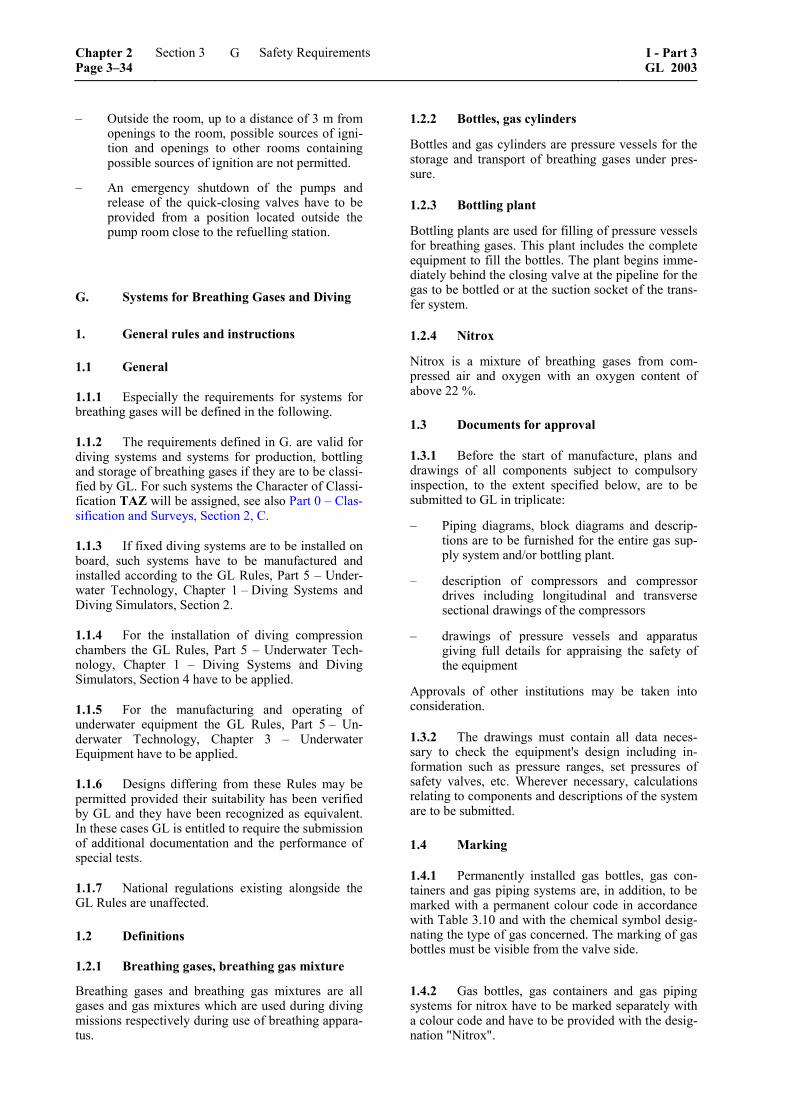
– Outside the room, up to a distance of 3 m from openings to the room, possible sources of igni-tion and openings to other rooms containing possible sources of ignition are not permitted.
– An emergency shutdown of the pumps and release of the quick-closing valves have to be provided from a position located outside the pump room close to the refuelling station.
G. Systems for Breathing Gases and Diving
1. General rules and instructions
1.1 General
1.1.1 Especially the requirements for systems for breathing gases will be defined in the following.
1.1.2 The requirements defined in G. are valid for diving systems and systems for production, bottling and storage of breathing gases if they are to be classi-fied by GL. For such systems the Character of Classi-fication TAZ will be assigned, see also Part 0 – Clas-sification and Surveys, Section 2, C.
1.1.3 If fixed diving systems are to be installed on board, such systems have to be manufactured and installed according to the GL Rules, Part 5 – Under-water Technology, Chapter 1 – Diving Systems and Diving Simulators, Section 2.
1.1.4 For the installation of diving compression chambers the GL Rules, Part 5 – Underwater Tech-nology, Chapter 1 – Diving Systems and Diving Simulators, Section 4 have to be applied.
1.1.5 For the manufacturing and operating of underwater equipment the GL Rules, Part 5 – Un-derwater Technology, Chapter 3 – Underwater Equipment have to be applied.
1.1.6 Designs differing from these Rules may be permitted provided their suitability has been verified by GL and they have been recognized as equivalent. In these cases GL is entitled to require the submission of additional documentation and the performance of special tests.
1.1.7 National regulations existing alongside the GL Rules are unaffected.
1.2 Definitions
1.2.1 Breathing gases, breathing gas mixture
Breathing gases and breathing gas mixtures are all gases and gas mixtures which are used during diving missions respectively during use of breathing appara-tus.
1.2.2 Bottles, gas cylinders
Bottles and gas cylinders are pressure vessels for the storage and transport of breathing gases under pres-sure.
1.2.3 Bottling plant
Bottling plants are used for filling of pressure vessels for breathing gases. This plant includes the complete equipment to fill the bottles. The plant begins imme-diately behind the closing valve at the pipeline for the gas to be bottled or at the suction socket of the trans-fer system.
1.2.4 Nitrox
Nitrox is a mixture of breathing gases from com-pressed air and oxygen with an oxygen content of above 22 %.
1.3 Documents for approval
1.3.1 Before the start of manufacture, plans and drawings of all components subject to compulsory inspection, to the extent specified below, are to be submitted to GL in triplicate:
– Piping diagrams, block diagrams and descrip-tions are to be furnished for the entire gas sup-ply system and/or bottling plant.
– description of compressors and compressor drives including longitudinal and transverse sectional drawings of the compressors
– drawings of pressure vessels and apparatus giving full details for appraising the safety of the equipment
Approvals of other institutions may be taken into consideration.
1.3.2 The drawings must contain all data neces-sary to check the equipment's design including in-formation such as pressure ranges, set pressures of safety valves, etc. Wherever necessary, calculations relating to components and descriptions of the system are to be submitted.
1.4 Marking
1.4.1 Permanently installed gas bottles, gas con-tainers and gas piping systems are, in addition, to be marked with a permanent colour code in accordance with Table 3.10 and with the chemical symbol desig-nating the type of gas concerned. The marking of gas bottles must be visible from the valve side.
1.4.2 Gas bottles, gas containers and gas piping systems for nitrox have to be marked separately with a colour code and have to be provided with the desig-nation "Nitrox".
Chapter 2 Page 3–34
Section 3 Safety Requirements I - Part 3GL 2003
G

Table 3.10 Marking of gas systems
Type of gas Chemical symbol Colour code
Oxygen O2 white
Nitrogen N2 black
Air –– white & black
1.4.3 Manometers for oxygen and/or nitrox have to be marked as free of oil and grease.
2. Principles for the design and construction of systems for breathing gases
2.1 General principles
2.1.1 Bottling plants are to be constructed and operated in a way that the operating, control and maintenance personnel or other persons in the prox-imity of the plant are not endangered.
2.1.2 Pipe connections between pressured air bottling plants for the production of breathing gases and other compressed air systems on board are only to be established with special approval of GL and under consideration of additional protection meas-ures.
2.1.3 Pipelines carrying gas or oxygen under high pressure shall not be routed through accommodation spaces, engine rooms or similar compartments.
2.1.4 Pipelines for mixed gases containing more than 25 % oxygen are to be treated as pure oxygen lines.
2.1.5 Filling pipes and intermediate or coupling pieces of filling pipes must be suitable to be released of pressure without danger.
2.1.6 Filling connections are to be constructed or marked in a way that confusion of the gases to be filled is safely avoided and a correct connection can be established.
2.1.7 At the gas draw-off position the bottling plant has to be equipped with a manometer which shows the supply pressure.
2.2 Pressure vessels and apparatus
Pressure vessels and apparatus under pressure are to be designed and manufactured according to the refer-ence in Section 1, C.
2.3 Compressors
2.3.1 The compressors must be suitable for an operation on board of seagoing yachts and are to be
operable under the actual operating and ambient conditions of the yacht.
2.3.2 Compressors are to be designed for the re-quired delivery rates, types of gas and delivery pres-sures.
2.3.3 Compressors are to be so designed that no lubricating oil can penetrate the gas circuit.
2.3.4 Compressors are to be so installed that no harmful gases can be sucked in.
2.3.5 Oxygen compressors are to be installed in separate spaces with adequate ventilation.
2.3.6 Compressors must be equipped with ade-quately designed suction filters, coolers and water separators.
2.3.7 The breathing air produced by the compres-sors must fulfil the requirements of EN 12021. Na-tional regulations are unaffected from this.
2.3.8 Each compressor stage must be equipped with a pressure relief valve or rupture disc, neither of which can be disabled. This safety device must be designed and set in such a way that the specified pressure in the compressor stage concerned cannot be exceeded by more than 10 %. The setting must be safeguarded against unauthorized alteration.
2.3.9 Each compressor stage must be provided with a suitable pressure gauge indicating clearly the final pressure of that stage.
2.3.10 Where a compressor stage comprises more than one cylinder and each cylinder can be closed off individually, a pressure relief valve and a pressure gauge must be provided for each cylinder.
2.3.11 Dry-running reciprocating compressors must be equipped at each stage with a device which acti-vates a warning signal and shuts down the drive mo-tor if the final compression temperature stated in the operating instructions is exceeded.
2.3.12 Diaphragm-type compressors must be equipped at each stage with a diaphragm rupture indicator which shuts down the compressor as soon as damage occurs to the drive or compressor dia-phragm.
2.3.13 Marking
A manufacturer's data plate containing the following details must be permanently fixed to each compres-sor:
– type designation
– manufacturer's name
– serial number
– year of manufacture
I - Part 3 GL 2003
Section 3 Safety Requirements Chapter 2Page 3–35
G

– flow mass
– delivery pressure
– revolutions per minute
2.4 Piping systems
2.4.1 Piping systems are to be constructed and manufactured on the basis of standards generally used in shipbuilding.
As far as it is not defined in detail in the following, pipelines of bottling plants have to fulfil the require-ments according to the reference in Section 1, C.
2.4.2 Expansion in piping systems is to be com-pensated by pipe bends or compensators. Attention is to be given to the suitable location of fixed points.
2.4.3 Means must be provided for the complete evacuation, drainage and venting of pipelines.
2.4.4 Pipelines which in service may be subject to pressures higher than the design pressure must be fitted with overpressure protection.
2.4.5 The use of hoses is to be restricted to a mini-mum and only short lengths have to be installed.
2.5 Pipe connections
2.5.1 Wherever possible, pipes should be joined by full-penetration butt welds.
2.5.2 Screwed pipe connections may only be made using bite joints approved by GL.
2.5.3 Flanged connections may be used provided that the flanges and flange bolts conform to a recog-nized standard.
2.6 Valves and fittings
2.6.1 Shut-off devices must conform to a recog-nized standard. Valves with screw-down bonnets or spindles are to be protected against unintentional unscrewing of the bonnet.
2.6.2 Manually operated shut-off devices are to be closed by turning in the clockwise direction.
2.6.3 Oxygen lines may only be fitted with screw-down valves, although ball valves may be used for emergency shut-off purposes.
2.6.4 Hose fittings are to be made of corrosion-resistant material and are to be so designed that they cannot be disconnected accidentally.
2.7 Materials
2.7.1 Materials must be suitable for the proposed application and must conform to the GL Rules II – Materials and Welding, Part 1 and 2.
2.7.2 Welds are to conform to the GL Rules, II-Materials and Welding, Chapter 3 – Welding in the Various Fields of Application, Section 4.
2.7.3 Materials for breathing gas systems shall not form any toxic or combustible products.
2.7.4 In oxygen systems, only those materials may be used which are approved for use with oxygen and which are suitable for the proposed operating condi-tions.
2.8 Electrical installation
The electrical installation has to meet the require-ments of Section 1, D.
Systems for breathing gases are to be provided with a sufficient compensation of electrical potential.
2.9 Control and monitoring
Bottling plants for breathing gases have to be oper-ated and monitored manually.
2.10 Additional requirements for breathing gas systems for nitrox and oxygen
2.10.1 Fittings for oxygen are to be constructed to avoid a burn-off or are to be so arranged or protected that the personnel can not be hurt in case of a burn-off.
2.10.2 Spindle valves for oxygen have to be con-structed for a nominal diameter above 15 mm and operating pressures of more than 40 bar in a way that the spindle thread is outside of the gas space.
2.10.3 Tighting materials containing combustible elements and which come into contact with com-pressed gases with oxidizable effects are only ap-proved for fittings if the suitability for the pressures, temperatures and type of installation is proven.
2.10.4 For oxygen armatures and fittings only lu-bricants are allowed which are approved for the ac-tual operating conditions.
2.10.5 Hoses must be suitable for oxygen.
Chapter 2 Page 3–36
Section 3 Safety Requirements I - Part 3GL 2003
G
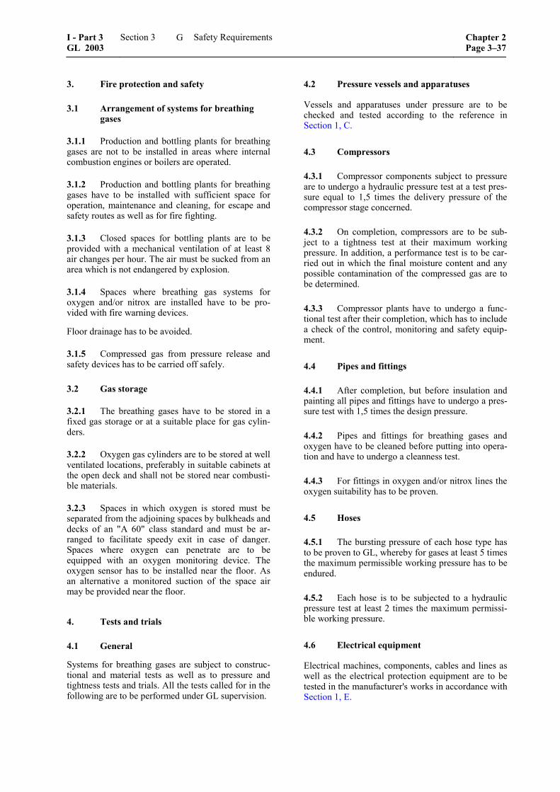
3. Fire protection and safety
3.1 Arrangement of systems for breathing gases
3.1.1 Production and bottling plants for breathing gases are not to be installed in areas where internal combustion engines or boilers are operated.
3.1.2 Production and bottling plants for breathing gases have to be installed with sufficient space for operation, maintenance and cleaning, for escape and safety routes as well as for fire fighting.
3.1.3 Closed spaces for bottling plants are to be provided with a mechanical ventilation of at least 8 air changes per hour. The air must be sucked from an area which is not endangered by explosion.
3.1.4 Spaces where breathing gas systems for oxygen and/or nitrox are installed have to be pro-vided with fire warning devices.
Floor drainage has to be avoided.
3.1.5 Compressed gas from pressure release and safety devices has to be carried off safely.
3.2 Gas storage
3.2.1 The breathing gases have to be stored in a fixed gas storage or at a suitable place for gas cylin-ders.
3.2.2 Oxygen gas cylinders are to be stored at well ventilated locations, preferably in suitable cabinets at the open deck and shall not be stored near combusti-ble materials.
3.2.3 Spaces in which oxygen is stored must be separated from the adjoining spaces by bulkheads and decks of an "A 60" class standard and must be ar-ranged to facilitate speedy exit in case of danger. Spaces where oxygen can penetrate are to be equipped with an oxygen monitoring device. The oxygen sensor has to be installed near the floor. As an alternative a monitored suction of the space air may be provided near the floor.
4. Tests and trials
4.1 General
Systems for breathing gases are subject to construc-tional and material tests as well as to pressure and tightness tests and trials. All the tests called for in the following are to be performed under GL supervision.
4.2 Pressure vessels and apparatuses
Vessels and apparatuses under pressure are to be checked and tested according to the reference in Section 1, C.
4.3 Compressors
4.3.1 Compressor components subject to pressure are to undergo a hydraulic pressure test at a test pres-sure equal to 1,5 times the delivery pressure of the compressor stage concerned.
4.3.2 On completion, compressors are to be sub-ject to a tightness test at their maximum working pressure. In addition, a performance test is to be car-ried out in which the final moisture content and any possible contamination of the compressed gas are to be determined.
4.3.3 Compressor plants have to undergo a func-tional test after their completion, which has to include a check of the control, monitoring and safety equip-ment.
4.4 Pipes and fittings
4.4.1 After completion, but before insulation and painting all pipes and fittings have to undergo a pres-sure test with 1,5 times the design pressure.
4.4.2 Pipes and fittings for breathing gases and oxygen have to be cleaned before putting into opera-tion and have to undergo a cleanness test.
4.4.3 For fittings in oxygen and/or nitrox lines the oxygen suitability has to be proven.
4.5 Hoses
4.5.1 The bursting pressure of each hose type has to be proven to GL, whereby for gases at least 5 times the maximum permissible working pressure has to be endured.
4.5.2 Each hose is to be subjected to a hydraulic pressure test at least 2 times the maximum permissi-ble working pressure.
4.6 Electrical equipment
Electrical machines, components, cables and lines as well as the electrical protection equipment are to be tested in the manufacturer's works in accordance with Section 1, E.
I - Part 3 GL 2003
Section 3 Safety Requirements Chapter 2Page 3–37
G

Annex A
Design Loads for Yachts of High Speed Type
On the following pages of this Annex we provide an excerpt of the GL Rules, Part 3 – Special Craft, Chapter 1 – High Speed Craft which contains the formulae to determine the design loads for yachts capable of speeds:
[ ]6v 7,2 kn≥ ⋅ Δ
See Section 2, E.3.1.1.
Note
The passages relevant for design load determination start with C.3.3 of the following page and end with C.3.5.10. Cross references in the following pages aim at the GL Rules, Part 3 – Special Craft, Chapter 1 –High Speed Craft.
I - Part 3 GL 2003
Annex A Design Loads for Yachts of High Speed Type Chapter 2Page A–1
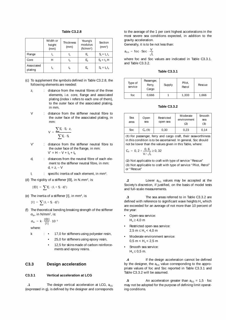
Table C3.2.8
(c) To supplement the symbols defined in Table C3.2.8, thefollowing elements are needed:
zi : distance from the neutral fibres of the threeelements, i.e. core, flange and associatedplating (index i refers to each one of them),to the outer face of the associated plating,in mm,
V : distance from the stiffener neutral fibre tothe outer face of the associated plating, inmm:
V’ : distance from the stiffener neutral fibre tothe outer face of the flange, in mm:
V’ = H − V + ts + tb
di : distances from the neutral fibre of each ele-ment to the stiffener neutral fibre, in mm:
di = zi − V
Ii : specific inertia of each element, in mm4.
(d) The rigidity of a stiffener [EI], in N.mm2, is:
(e) The inertia of a stiffener [I], in mm4, is:
(f) The theoretical bending breaking strength of the stiffenerσbr, in N/mm2, is:
where:
k : • 17,0 for stiffeners using polyester resin,
• 25,0 for stiffeners using epoxy resin,
• 12,5 for skins made of carbon reinforce-ments and epoxy resins.
C3.3 Design acceleration
C3.3.1 Vertical acceleration at LCG
.1 The design vertical acceleration at LCG, aCG
(expressed in g), is defined by the designer and corresponds
to the average of the 1 per cent highest accelerations in themost severe sea conditions expected, in addition to thegravity acceleration.Generally, it is to be not less than:
where foc and Soc values are indicated in Table C3.3.1.and Table C3.3.2.
Table C3.3.1
Table C3.3.2
.2 Lower aCG values may be accepted at theSociety’s discretion, if justified, on the basis of model testsand full-scale measurements.
.3 The sea areas referred to in Table C3.3.2 aredefined with reference to significant wave heights Hs whichare exceeded for an average of not more than 10 percent ofthe year:
• Open-sea service:Hs ≥ 4,0 m
• Restricted open-sea service:2,5 m ≤ Hs < 4,0 m
• Moderate environment service:0,5 m < Hs < 2,5 m
• Smooth sea service:Hs ≤ 0,5 m.
.4 If the design acceleration cannot be definedby the designer, the aCG value corresponding to the appro-priate values of foc and Soc reported in Table C3.3.1 andTable C3.3.2 will be assumed.
.5 An acceleration greater than aCG = 1,5 ⋅ focmay not be adopted for the purpose of defining limit operat-ing conditions.
Width orheight (mm)
Thickness(mm)
Young’s modulus (N/mm2)
Section(mm2)
Flange Is ts Es Ss = ts Is
Core H ta Ea Sa = ta H
Associatedplating
Ib tb Eb Sb = tb Ib
VEi Si zi⋅ ⋅�
Ei Si⋅�-----------------------------=
EI[ ] Ei Ii Si+ di2⋅( )⋅�=
I[ ] Ii Si di2⋅+( )�=
σbr k EI[ ]I[ ]--------- 10 3–⋅ ⋅=
Type of service
Passenger,Ferry,Cargo
SupplyPilot,Patrol
Rescue
foc 0,666 1 1,333 1,666
Seaarea
Open sea
Restricted open sea
Moderate environment
(2)
Smooth sea(3)
Soc CF (1) 0,30 0,23 0,14
(1) For passenger, ferry and cargo craft, their seaworthinessin this condition is to be ascertained. In general, Soc should not be lower than the values given in this Table, where:
(2) Not applicable to craft with type of service “Rescue”(3) Not applicable to craft with type of service “Pilot, Patrol”or “Rescue”
aCG foc Soc VL-------⋅ ⋅=
CF 0 2, 0 6,V L⁄---------------+ 0 32,≥=
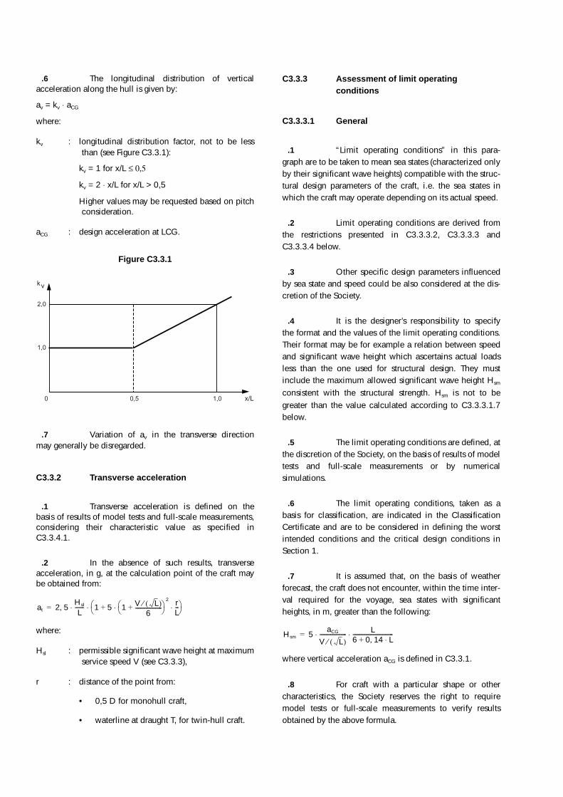
.6 The longitudinal distribution of verticalacceleration along the hull is given by:
av = kv ⋅ aCG
where:
kv : longitudinal distribution factor, not to be lessthan (see Figure C3.3.1):
kv = 1 for x/L ≤ 0,5
kv = 2 ⋅ x/L for x/L > 0,5
Higher values may be requested based on pitchconsideration.
aCG : design acceleration at LCG.
Figure C3.3.1
.7 Variation of av in the transverse directionmay generally be disregarded.
C3.3.2 Transverse acceleration
.1 Transverse acceleration is defined on thebasis of results of model tests and full-scale measurements,considering their characteristic value as specified inC3.3.4.1.
.2 In the absence of such results, transverseacceleration, in g, at the calculation point of the craft maybe obtained from:
where:
Hsl : permissible significant wave height at maximumservice speed V (see C3.3.3),
r : distance of the point from:
• 0,5 D for monohull craft,
• waterline at draught T, for twin-hull craft.
C3.3.3 Assessment of limit operating conditions
C3.3.3.1 General
.1 “Limit operating conditions” in this para-graph are to be taken to mean sea states (characterized onlyby their significant wave heights) compatible with the struc-tural design parameters of the craft, i.e. the sea states inwhich the craft may operate depending on its actual speed.
.2 Limit operating conditions are derived fromthe restrictions presented in C3.3.3.2, C3.3.3.3 andC3.3.3.4 below.
.3 Other specific design parameters influencedby sea state and speed could be also considered at the dis-cretion of the Society.
.4 It is the designer’s responsibility to specifythe format and the values of the limit operating conditions.Their format may be for example a relation between speedand significant wave height which ascertains actual loadsless than the one used for structural design. They mustinclude the maximum allowed significant wave height Hsm
consistent with the structural strength. Hsm is not to begreater than the value calculated according to C3.3.3.1.7below.
.5 The limit operating conditions are defined, atthe discretion of the Society, on the basis of results of modeltests and full-scale measurements or by numericalsimulations.
.6 The limit operating conditions, taken as abasis for classification, are indicated in the ClassificationCertificate and are to be considered in defining the worstintended conditions and the critical design conditions inSection 1.
.7 It is assumed that, on the basis of weatherforecast, the craft does not encounter, within the time inter-val required for the voyage, sea states with significantheights, in m, greater than the following:
where vertical acceleration aCG is defined in C3.3.1.
.8 For craft with a particular shape or othercharacteristics, the Society reserves the right to requiremodel tests or full-scale measurements to verify resultsobtained by the above formula.
2,0
0
1,0
kv
x/L0,5 1,0
at 2 5, Hsl
L------- 1 5 1 V L( )⁄
6--------------------+
� �� �
2 rL---⋅ ⋅+
� �� �⋅ ⋅=
Hsm 5aCG
V L( )⁄-------------------- L
6 0 14 L⋅,+------------------------------⋅ ⋅=

C3.3.3.2 Limitation imposed by bottom impact pressure and deck loads
.1 Bottom impact pressure, given in C3.5.3,and deck loads, given in C3.5.8, are explicitly or implicitlydepending on the vertical acceleration at LCG. Therefore,the design values of these loads, taken as the basis for theclassification, directly impose limitation on vertical acceler-ation level at LCG.
.2 It is the designer’s responsibility to providefor a relation between the speed and the significant waveheight that provides a maximum vertical acceleration lessthan the design value.
.3 Model tests if any are to be carried out inirregular sea conditions with a significant wave height cor-responding to the operating conditions of the craft and aclearly specified sea spectrum. The scale effect is to beaccounted for with an appropriate margin of safety. Thecharacteristic value of acceleration and global loads to beassumed corresponds to the average of the 1 per cent high-est values obtained during tests. The duration of the test is,as far as practicable, to be sufficient to guarantee that resultsare stationary.
.4 Where model test results or full-scale meas-urements are not available, the formula contained inC3.3.3.2.5 may be used to define maximum speeds com-patible with design acceleration of monohulls, dependingon sea states having a significant height Hs.
.5 The significant wave height is related to thecraft’s geometric and motion characteristics and to the verti-cal acceleration aCG by the following formula:
• for units for which V / L0,5 ≥ 3 and ∆ / (0,01 ⋅ L)3 ≥ 3500
and
• for units for which V/L0,5 < 3 or ∆/(0,01 ⋅ L)3 < 3500
and
where:
Hs : significant wave height, in m,
αdCG : deadrise angle, in degrees, at LCG, to be takenbetween 10° and 30°,
τ : trim angle during navigation, in degrees, to betaken not less than 4°,
V : maximum service speed, in knots.
Vx : actual craft speed, in knots.
If Vx is replaced by the maximum service speed V of thecraft, the previous formula yields the significant height ofthe limit sea state, Hsl. This formula may also be used tospecify the permissible speed in a sea state characterised bya significant wave height equal to or greater than Hsl.
.6 On the basis of the formula indicated inC3.3.3.2.5, the limit sea state may be defined (characterisedby its significant wave height Hsl), i.e. the sea state in whichthe craft may operate at its maximum service speed. Duringits voyage, whenever the craft encounters waves having asignificant height greater than Hsl, it has to reduce its speed.
.7 For catamarans, the relation between speed,wave height and acceleration is to be justified by model testresults or full-scale measurements (see also C3.3.3.3).
.8 For craft, such as SESs, for which a speedreduction does not necessarily imply a reduction in acceler-ation, the speed is to be modified depending on the seastate according to criteria defined, at the discretion of theSociety, on the basis of motion characteristics of the craft.
.9 The reduction of vertical acceleration aCG
induced by stabilisation system if any is to be disregardedfor the purpose of limit operating conditions imposed bybottom impact loads.
C3.3.3.3 Limitation imposed by wet deck impact loads for catamarans
.1 Wet deck impact pressure is given in C3.5.4.
.2 The formula in C3.5.4 may be used to definemaximum speeds compatible with actual structure of wetdeck, depending on sea states having a significant heightHs.
.3 The reduction of relative impact velocity Vsl
induced by stabilisation system if any is to be disregardedfor the purpose of limit operating conditions imposed bywet deck impact loads.
C3.3.3.4 Limitation imposed by global loads
.1 For monohulls and catamarans, the longitu-dinal bending moment and shear forces as given in C3.4.1and C3.4.2 are explicitly or implicitly depending on verticalacceleration along the ship. Therefore, the design values ofthese loads, taken as the basis for classification, directlyimpose limitation on vertical acceleration level at LCG. Therequirements of C3.3.3.2.2 to C3.3.3.2.9 apply.
.2 For catamarans, the transverse bendingmoment, the torsional bending moment and the verticalshear force as given in C3.4.2 are depending on verticalacceleration aCG. Therefore, the requirements of C3.3.3.2.2to C3.3.3.2.9 apply.
aCG
50 αdCG–( ) τ16------ 0 75,+� �� �⋅
3555 CB⋅----------------------------------------------------------------- HS
T------ 0 084, BW
T-------⋅+� �
� � KFR KHS⋅ ⋅ ⋅=
KFRVX
L-------� �� �
2
=
KHS 1=
KFR 0 8, 1 6, VX
L-------⋅+=
KHSHS
T------=

.3 For SWATH craft, the global loads as givenin C3.4.3 are not depending on ship motions.
.4 For ships with length greater than 100m, therelation between vertical acceleration along the ship andglobal loads are to be ascertained on basis of results ofmodel tests and/or full-scale measurements or by numericalsimulations, as indicated in C3.3.3.2.
.5 The reduction of vertical acceleration alongthe ship induced by stabilisation system if any is to be disre-garded for the purpose of limit operating conditionsimposed by global loads.
C3.3.3.5 Hull monitoring
.1 The Society may require a hull monitoringsystem to be fitted on board, allowing to monitor and dis-play in real time the vertical acceleration and any othersensitive parameter with respect to the strength.
.2 The information is to be available at thewheelhouse and displayed in a clear format allowing tocompare with design values.
.3 When a hull monitoring system is requested,its specification is to be submitted for review.
C3.4 Overall loads
C3.4.1 Monohulls
C3.4.1.1 General
.1 As a rule, only longitudinal vertical bendingmoment and shear force are to be considered formonohulls.
.2 For large craft, values from model tests, orhydrodynamic calculations, may be taken into account,after agreement of the Society on the methodology, the seaconditions and the loading cases. in such cases, valuesgiven in C3.4.1.2 must be considered as short term 1/100°values.
C3.4.1.2 Bending moment and shear force
.1 General
.1 The values of the longitudinal bending momentand shear force are given, in first approxima-tion, by the formula in C3.4.1.2.2, C3.4.1.2.3and C3.4.1.2.4.
.2 The total bending moments MblH, in hoggingconditions, and MblS, in sagging conditions, inkN.m, are to be taken as the greatest of thosegiven by the formulae in C3.4.1.2.2 andC3.4.1.2.3.
For ships having L > 100 m, only the formula inC3.4.1.2.3 is generally to be applied; the for-mula in C3.4.1.2.2 is to be applied whendeemed necessary by the Society on the basis ofthe motion characteristics of the ship. The totalshear forces Tbl, in kN, is given by the formulain C3.4.1.2.4.
.3 The longitudinal distribution of the total bend-ing moment MblH and MblS is given inC3.4.1.2.5.
.4 If the actual distribution of weights along thecraft is known, a more accurate calculation maybe carried out according to the procedure inC3.4.1.2.6. the Society reserves the right torequire calculation to be carried out accordingto C3.4.1.2.6 whenever it deems necessary.
.5 Rule requirements are reminded in TableC3.4.1.
Table C3.4.1
Ships Applicable requirements
L ≤ 100 m All casesBending moment C3.4.1.2.2 or C3.4.1.2.3 whichever is the greater
Shear force C3.4.1.2.4
L ≤ 100 mAlternatively, when actualdistribution of weights is known
Bending moment and shear force C3.4.1.2.6
L > 100 m Normal casesBending moment C3.4.1.2.3
Shear force C3.4.1.2.4
L > 100 mSpecial cases (when deemednecessary by the Society)
Bending moment C3.4.1.2.2 or C3.4.1.2.3 whichever is the greater
Shear force C3.4.1.2.4
L > 100 mAlternatively, when actualdistribution of weights is known
Bending moment and shear force C3.4.1.2.6

.2 Bending moment due to still water loads, wave induced loads and impact loads
where aCG is the vertical acceleration at the LCG, defined inC3.3.1.
.3 Bending moment due to still water loads and wave induced loads
where:
MsH : still water hogging bending moment, in kN.m,
MsS : still water sagging bending moment, in kN.m,
Soc : parameter as indicated in Table C3.3.2, for theconsidered type of service.
C = 6 + 0,02 L
For the purpose of this calculation, CB may not be taken lessthan 0,6.
.4 Total shear force
where:
Mbl : the greatest between MblH and MblS, calculatedaccording to C3.4.1.2.2 and C3.4.1.2.3, asapplicable.
.5 Longitudinal distribution of total bending moment
The longitudinal distribution of the total bending momentsis given by:
KM ⋅ MblH in hogging
KM ⋅ MblS in sagging
where:
KM : longitudinal distribution factor as shown on Fig-ure C3.4.1.
Figure C3.4.1
.6 Bending moment and shear force taking into account the actual distribution of weights
.1 The distribution of quasi-static bending momentand shear force, due to still water loads andwave induced loads, is to be determined fromthe difference in weight and buoyancy distribu-tions in hogging and sagging for each loading orballast condition envisaged.
.2 For calculation purposes, the following valuesare to be taken for the design wave:
• wave length, in m:
λ = L
• wave height, in m:
• wave form: sinusoidal.
.3 In addition, the increase in bending momentand shear force, due to impact loads in the fore-body area, for the sagging condition only, is tobe determined as specified below. For the pur-pose of this calculation, the hull is consideredlongitudinally subdivided into a number ofintervals, to be taken, in general, equal to 20.For smaller craft, this number may be reducedto 10 if justified, at the Society’s discretion, onthe basis of the weight distribution, the hullforms and value of the design acceleration aCG.
For twin-hull craft, the calculation belowapplies to one of the hulls, i.e. the longitudinaldistribution of weight forces gi and the corre-sponding breadth Bi are to be defined for onehull.
The total impact force, in kN, is:
where:
∆xi : length of interval, in m,
qSLi : additional load per unit length, inkN/m, for x/L ≥ 0,6 (see also FigureC3.4.2), given by:
xi : distance, in m, from the aftperpendicular,
MblH MblS 0 55 ∆ L CB 0 7,+( ) 1 aCG+( )⋅ ⋅ ⋅ ⋅,= =
MblH MsH 0 60 Soc C L2 B CB⋅ ⋅ ⋅ ⋅ ⋅,+=MblS MsS 0 35 Soc C L2 B CB 0 7,+( )⋅ ⋅ ⋅ ⋅ ⋅,+=
Tbl3 2, Mbl⋅
L----------------------=
0
1,0
0,50,40,30,20,1 1,00,90,80,70,60
x / L
KM
h L
15 L20------+
-------------------=
FSL qSLi xi∆⋅�=
qSLi p0 Bi 2 π xi
L---- 0 6,–� �� �⋅ ⋅� �
� �sin⋅ ⋅=
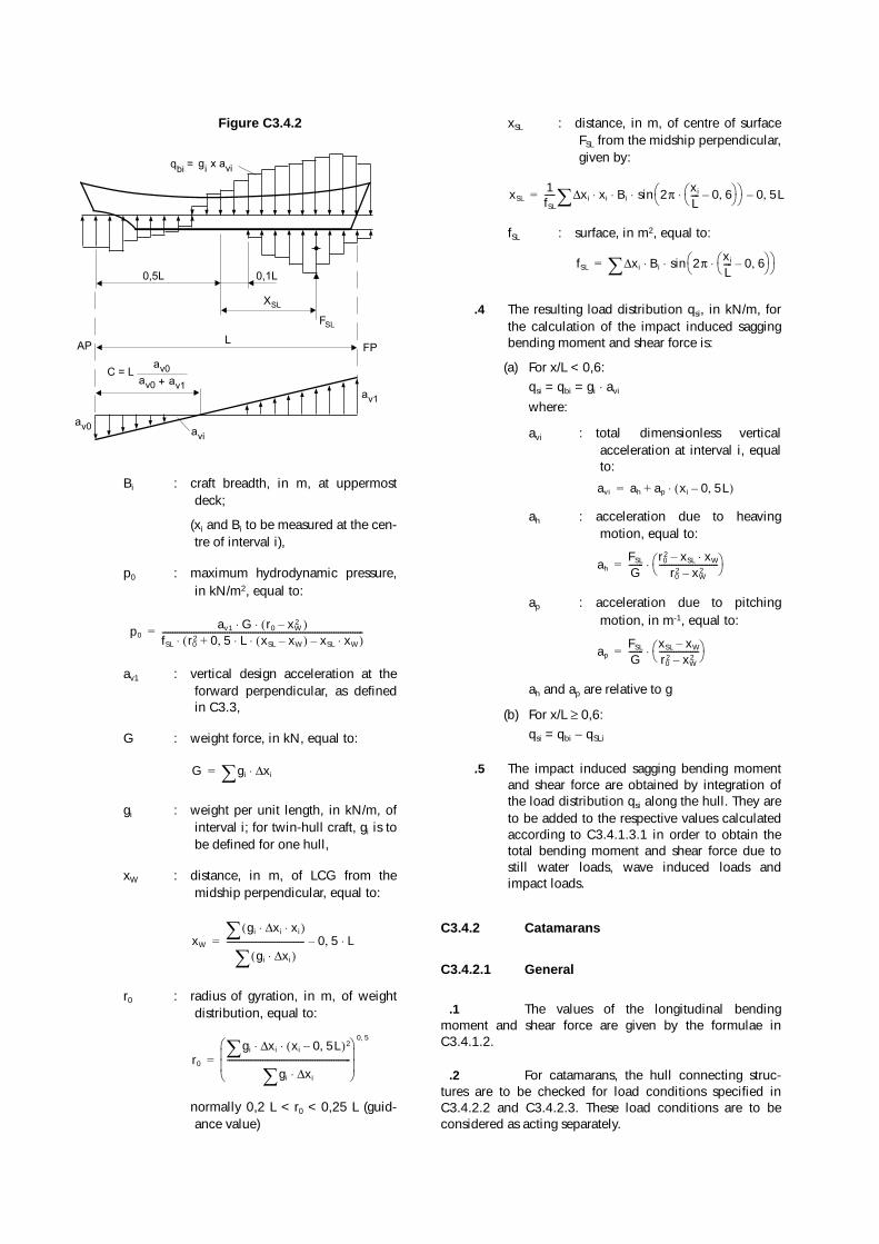
Figure C3.4.2
Bi : craft breadth, in m, at uppermostdeck;
(xi and Bi to be measured at the cen-tre of interval i),
p0 : maximum hydrodynamic pressure,in kN/m2, equal to:
av1 : vertical design acceleration at theforward perpendicular, as definedin C3.3,
G : weight force, in kN, equal to:
gi : weight per unit length, in kN/m, ofinterval i; for twin-hull craft, gi is tobe defined for one hull,
xW : distance, in m, of LCG from themidship perpendicular, equal to:
r0 : radius of gyration, in m, of weightdistribution, equal to:
normally 0,2 L < r0 < 0,25 L (guid-ance value)
xSL : distance, in m, of centre of surfaceFSL from the midship perpendicular,given by:
fSL : surface, in m2, equal to:
.4 The resulting load distribution qsi, in kN/m, forthe calculation of the impact induced saggingbending moment and shear force is:
(a) For x/L < 0,6:qsi = qbi = gi ⋅ avi
where:
avi : total dimensionless verticalacceleration at interval i, equalto:
ah : acceleration due to heavingmotion, equal to:
ap : acceleration due to pitchingmotion, in m-1, equal to:
ah and ap are relative to g
(b) For x/L ≥ 0,6:qsi = qbi − qSLi
.5 The impact induced sagging bending momentand shear force are obtained by integration ofthe load distribution qsi along the hull. They areto be added to the respective values calculatedaccording to C3.4.1.3.1 in order to obtain thetotal bending moment and shear force due tostill water loads, wave induced loads andimpact loads.
C3.4.2 Catamarans
C3.4.2.1 General
.1 The values of the longitudinal bendingmoment and shear force are given by the formulae inC3.4.1.2.
.2 For catamarans, the hull connecting struc-tures are to be checked for load conditions specified inC3.4.2.2 and C3.4.2.3. These load conditions are to beconsidered as acting separately.
AP
0,1L0,5L
XSL
LFP
FSL
C = Lav0
av0 + av1
av0avi
av1
qbi= g x a
i vi
p0av1 G r0 xW
2–( )⋅ ⋅fSL r0
2 0 5 L xSL xW–( ) xSL xW⋅–⋅ ⋅,+( )⋅------------------------------------------------------------------------------------------------=
G gi xi∆⋅�=
xW
gi xi∆ xi⋅ ⋅( )�
gi xi∆⋅( )�------------------------------------- 0 5 L⋅,–=
r0
gi xi∆ xi 0 5L,–( )2⋅ ⋅�
gi xi∆⋅�-----------------------------------------------------------� �� �� �� �
0 5,
=
xSL1fSL
----- xi∆ xi Bi⋅ ⋅ 2π xi
L---- 0 6,–� �� �⋅
� �� �sin 0 5L,–⋅�=
fSL xi∆ Bi⋅ 2π xi
L---- 0 6,–� �� �⋅
� �� �sin⋅�=
avi ah ap xi 0 5L,–( )⋅+=
ahFSL
G------- r0
2 xSL xW⋅–r0
2 xW2–
----------------------------� �� �⋅=
apFSL
G------- xSL xW–
r02 xW
2–-------------------� �� �⋅=
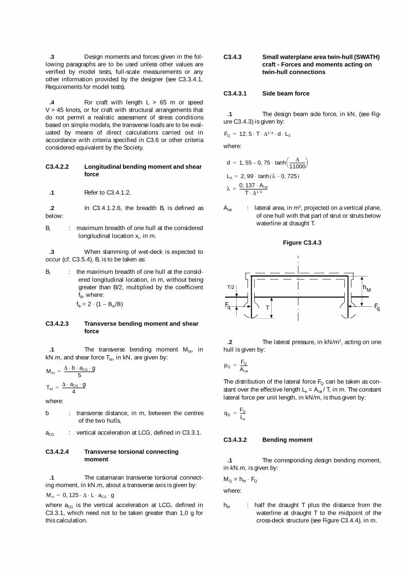
.3 Design moments and forces given in the fol-lowing paragraphs are to be used unless other values areverified by model tests, full-scale measurements or anyother information provided by the designer (see C3.3.4.1,Requirements for model tests).
.4 For craft with length L > 65 m or speedV > 45 knots, or for craft with structural arrangements thatdo not permit a realistic assessment of stress conditionsbased on simple models, the transverse loads are to be eval-uated by means of direct calculations carried out inaccordance with criteria specified in C3.6 or other criteriaconsidered equivalent by the Society.
C3.4.2.2 Longitudinal bending moment and shear force
.1 Refer to C3.4.1.2.
.2 In C3.4.1.2.6, the breadth Bi is defined asbelow:
Bi : maximum breadth of one hull at the consideredlongitudinal location xi, in m.
.3 When slamming of wet-deck is expected tooccur (cf. C3.5.4), Bi is to be taken as:
Bi : the maximum breadth of one hull at the consid-ered longitudinal location, in m, without beinggreater than B/2, multiplied by the coefficientfB, where:
fB = 2 ⋅ (1 − Βw/Β)
C3.4.2.3 Transverse bending moment and shear force
.1 The transverse bending moment Mbt, inkN.m, and shear force Tbt, in kN, are given by:
where:
b : transverse distance, in m, between the centresof the two hulls,
aCG : vertical acceleration at LCG, defined in C3.3.1.
C3.4.2.4 Transverse torsional connecting moment
.1 The catamaran transverse torsional connect-ing moment, in kN.m, about a transverse axis is given by:
where aCG is the vertical acceleration at LCG, defined inC3.3.1, which need not to be taken greater than 1,0 g forthis calculation.
C3.4.3 Small waterplane area twin-hull (SWATH) craft - Forces and moments acting on twin-hull connections
C3.4.3.1 Side beam force
.1 The design beam side force, in kN, (see Fig-ure C3.4.3) is given by:
where:
Alat : lateral area, in m2, projected on a vertical plane,of one hull with that part of strut or struts belowwaterline at draught T.
Figure C3.4.3
.2 The lateral pressure, in kN/m2, acting on onehull is given by:
The distribution of the lateral force FQ can be taken as con-stant over the effective length Le = Alat / T, in m. The constantlateral force per unit length, in kN/m, is thus given by:
C3.4.3.2 Bending moment
.1 The corresponding design bending moment,in kN.m, is given by:
MQ = hM ⋅ FQ
where:
hM : half the draught T plus the distance from thewaterline at draught T to the midpoint of thecross-deck structure (see Figure C3.4.4), in m.
Mbt∆ b aCG g⋅ ⋅ ⋅
5--------------------------------=
Tbt∆ aCG g⋅ ⋅
4------------------------=
Mtt 0 125 ∆ L aCG g⋅ ⋅ ⋅ ⋅,=
FQ 12 5 T ∆2 3/ d LS⋅ ⋅ ⋅ ⋅,=
d 1 55 0 75, ∆11000----------------� �� �tanh⋅–,=
LS 2 99 λ 0 725,–( )tanh⋅,=
λ 0 137 Alat⋅,T ∆1 3/⋅
-----------------------------=
TFq
T/2
Fq
hM
pQFQ
Alat
--------=
qQFQ
Le
------=
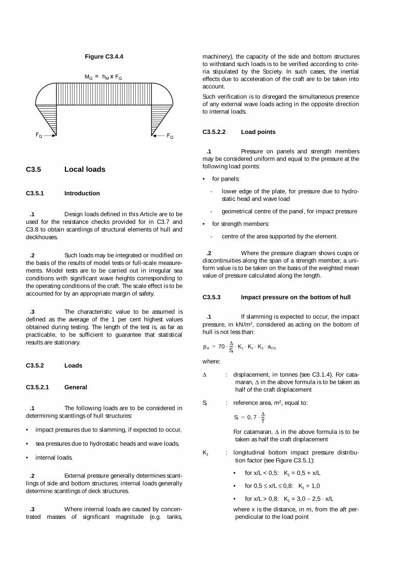
Figure C3.4.4
C3.5 Local loads
C3.5.1 Introduction
.1 Design loads defined in this Article are to beused for the resistance checks provided for in C3.7 andC3.8 to obtain scantlings of structural elements of hull anddeckhouses.
.2 Such loads may be integrated or modified onthe basis of the results of model tests or full-scale measure-ments. Model tests are to be carried out in irregular seaconditions with significant wave heights corresponding tothe operating conditions of the craft. The scale effect is to beaccounted for by an appropriate margin of safety.
.3 The characteristic value to be assumed isdefined as the average of the 1 per cent highest valuesobtained during testing. The length of the test is, as far aspracticable, to be sufficient to guarantee that statisticalresults are stationary.
C3.5.2 Loads
C3.5.2.1 General
.1 The following loads are to be considered indetermining scantlings of hull structures:
• impact pressures due to slamming, if expected to occur,
• sea pressures due to hydrostatic heads and wave loads,
• internal loads.
.2 External pressure generally determines scant-lings of side and bottom structures; internal loads generallydetermine scantlings of deck structures.
.3 Where internal loads are caused by concen-trated masses of significant magnitude (e.g. tanks,
machinery), the capacity of the side and bottom structuresto withstand such loads is to be verified according to crite-ria stipulated by the Society. In such cases, the inertialeffects due to acceleration of the craft are to be taken intoaccount.
Such verification is to disregard the simultaneous presenceof any external wave loads acting in the opposite directionto internal loads.
C3.5.2.2 Load points
.1 Pressure on panels and strength membersmay be considered uniform and equal to the pressure at thefollowing load points:
• for panels:
- lower edge of the plate, for pressure due to hydro-static head and wave load
- geometrical centre of the panel, for impact pressure
• for strength members:
- centre of the area supported by the element.
.2 Where the pressure diagram shows cusps ordiscontinuities along the span of a strength member, a uni-form value is to be taken on the basis of the weighted meanvalue of pressure calculated along the length.
C3.5.3 Impact pressure on the bottom of hull
.1 If slamming is expected to occur, the impactpressure, in kN/m2, considered as acting on the bottom ofhull is not less than:
where:
∆ : displacement, in tonnes (see C3.1.4). For cata-maran, ∆ in the above formula is to be taken ashalf of the craft displacement
Sr : reference area, m2, equal to:
For catamaran, ∆ in the above formula is to betaken as half the craft displacement
K1 : longitudinal bottom impact pressure distribu-tion factor (see Figure C3.5.1):
• for x/L < 0,5: K1 = 0,5 + x/L
• for 0,5 ≤ x/L ≤ 0,8: K1 = 1,0
• for x/L > 0,8: K1 = 3,0 − 2,5 ⋅ x/L
where x is the distance, in m, from the aft per-pendicular to the load point
FQ
MQ = hM x FQ
FQ
psl 70 ∆Sr
---- K1 K2 K3 aCG⋅ ⋅ ⋅ ⋅ ⋅=
Sr 0 7 ∆T---⋅,=
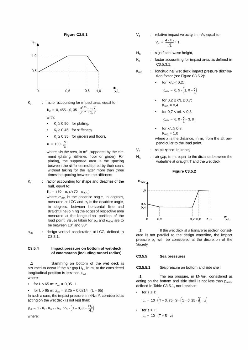
Figure C3.5.1
K2 : factor accounting for impact area, equal to:
with:
• K2 ≥ 0,50 for plating,
• K2 ≥ 0,45 for stiffeners,
• K2 ≥ 0,35 for girders and floors,
where s is the area, in m2, supported by the ele-ment (plating, stiffener, floor or girder). Forplating, the supported area is the spacingbetween the stiffeners multiplied by their span,without taking for the latter more than threetimes the spacing between the stiffeners
K3 : factor accounting for shape and deadrise of thehull, equal to:
where αdCG is the deadrise angle, in degrees,measured at LCG and αd is the deadrise angle,in degrees, between horizontal line andstraight line joining the edges of respective areameasured at the longitudinal position of theload point; values taken for αd and αdCG are tobe between 10° and 30°
aCG : design vertical acceleration at LCG, defined inC3.3.1.
C3.5.4 Impact pressure on bottom of wet-deck of catamarans (including tunnel radius)
.1 Slamming on bottom of the wet deck isassumed to occur if the air gap HA,, in m, at the consideredlongitudinal position is less than zwd,
where:
• for L ≤ 65 m: zwd = 0,05 ⋅ L
• for L > 65 m: zwd = 3,25 + 0,0214 ⋅ (L − 65)In such a case, the impact pressure, in kN/m2, considered asacting on the wet deck is not less than:
where:
Vsl : relative impact velocity, in m/s, equal to:
HS : significant wave height,
K2 : factor accounting for impact area, as defined inC3.5.3.1,
KWD : longitudinal wet deck impact pressure distribu-tion factor (see Figure C3.5.2):
• for x/L < 0,2:
• for 0,2 ≤ x/L ≤ 0,7:KWD = 0,4
• for 0,7 < x/L < 0,8:
• for x/L ≥ 0,8:KWD = 1,0
where x is the distance, in m, from the aft per-pendicular to the load point,
VX : ship’s speed, in knots,
HA : air gap, in m, equal to the distance between thewaterline at draught T and the wet deck
Figure C3.5.2
.2 If the wet deck at a transverse section consid-ered is not parallel to the design waterline, the impactpressure psl will be considered at the discretion of theSociety.
C3.5.5 Sea pressures
C3.5.5.1 Sea pressure on bottom and side shell
.1 The sea pressure, in kN/m2, considered asacting on the bottom and side shell is not less than psmin,defined in Table C3.5.1, nor less than:
• for z ≤ T:
• for z > T:
K1
1,0
1,00,80 x/L
0,5
0,5
K2 0 455 0 35, u0 75, 1 7,–u0 75, 1 7,+---------------------------⋅–,=
u 100 sSr
----⋅=
K3 70 αd–( ) 70 αdCG–( )⁄=
psl 3 K2 KWD VX VSL⋅ 1 0 85, HA
HS
-------⋅–� �� �⋅ ⋅ ⋅ ⋅=
Vsl4 HS⋅
L-------------- 1+=
KWD 0 5, 1 0, xL---–� �
� �⋅=
KWD 6 0, xL---⋅ 3 8,–=
KWD
1,0
1,00,80 x/L0,2 0,7
0,5
0,4
ps 10 T 0 75 S 1 0 25 ST---⋅,–
� �� � z⋅–⋅,+� �
� �⋅=
ps 10 T S z–+( )⋅=

where:
z : vertical distance, in m, from the moulded baseline to load point. z is to be taken positivelyupwards,
S : as given, in m, in Table C3.5.1 with CB takennot greater than 0,5.
Table C3.5.1
.2 Between midship area and fore end(0,5 < x/L < 0,9), ps varies in a linear way as follows:
where psFP is the sea pressure at fore end and psM in midshiparea.
C3.5.5.2 Stern doors and side shell doors
.1 The sea pressures on stern doors and sideshell doors is to be taken according to C3.5.5.1 for scant-lings of plating and secondary members.
.2 The design forces, in kN, considered for thescantlings of primary members are to be not less than:
• external force: Fe = A ⋅ ps
• internal force: Fi = Fo + 10 ⋅ Wwhere:
A : area, in m, of the door opening,
W : mass of the door, in t,
Fp : total packing force in kN. Packing line pressureis normally not to be taken less than 5 N/mm,
Fo : the greater of Fc and 5 ⋅ A (kN),
Fc : accidental force, in kN, due to loose of cargoetc., to be uniformly distributed over the area Aand not to be taken less than 300 kN. For smalldoors, such as bunker doors and pilot doors,the value of Fc may be appropriately reduced.However, the value of Fc may be taken as zero,provided an additional structure such as aninner ramp is fitted, which is capable of pro-tecting the door from accidental forces due toloose cargoes,
ps : sea pressure as defined in C3.5.5.1
.3 The design forces, in kN, considered for thescantlings of securing or supporting devices of doors open-ing outwards are to be not less than:
• external force: Fe = A ⋅ ps
• internal force: Fi = Fo + 10 ⋅ W + Fp
where the parameters are defined in C3.5.5.2.2.
.4 The design forces, in kN, considered for thescantlings of securing or supporting devices of doors open-ing inwards are to be not less than:
• external force: Fe = A ⋅ ps + Fp
• internal force: Fi = Fo + 10 ⋅ Wwhere the parameters are defined in C3.5.5.2.2.
C3.5.6 Sea pressures on front walls of the hull
.1 The pressure, kN/m2, considered as acting onfront walls of the hull (in case of stepped main deck), notlocated at the fore end, is not less than:
where:
x1 : distance, in m, from front walls to the midshipperpendicular (for front walls aft of the midshipperpendicular, x1 is equal to 0),
z1 : distance, in m, from load point to waterline atdraught T.
Where front walls are inclined backwards, the pressure cal-culated above can be reduced to (psF sin α), where α is theangle in degree between front wall and deck.psF is not less than the greater of:3 + (6,5 + 0,06 ⋅ L) ⋅ sin α3 + 2,4 ⋅ aCG
.2 For front walls located at the fore end, thepressure psF will be individually considered by the Society.
C3.5.7 Sea pressures on deckhouses
.1 The pressure, kN/m2, considered as acting onwalls of deckhouses is not less than:
where:
Ksu : coefficient equal to:
• for front walls of a deckhouse locateddirectly on the main deck not at the foreend:Ksu = 6,0
• for unprotected front walls of the secondtier, not located at the fore end:Ksu = 5,0
• for sides of deckhouses, b being thebreadth, in m, of the considereddeckhouse:Ksu = 1,5 + 3,5 b/B (with 3 <= K <= 5)
• for the other walls:Ksu = 3,0
S psmin
x/L ≥ 0,9
x/L ≤ 0,5
T 0 36 aCGL
CB-------⋅ ⋅, 3 5 T⋅,≤ ≤ 20 L 75+
5---------------- 35≤ ≤
T 0 60 aCG L⋅ ⋅, 2 5 T⋅,≤ ≤ 10 L 75+10
---------------- 20≤ ≤
ps psFP 2 25 2 5 x L )⁄⋅,–, psFP psM–( )⋅( )–=
psf 6 1 x1
2 L CB 0 1,+( )⋅--------------------------------------+� �
� � 1 0 045 L 0 38 z1⋅,–⋅,+( )⋅=
psu Ksu 1 x1
2 L CB 0 1,+( )⋅--------------------------------------+� �
� � 1 0 045 L 0 38 z1⋅,–⋅,+( )⋅=
x1 : distance, in m, from front walls or from wall ele-ments to the midship perpendicular (for frontwalls or side walls aft of the midship perpen-dicular, x1 is equal to 0),
z1 : distance, in m, from load point to waterline atdraught T.
.2 The minimum values of psu, in kN/m2, to beconsidered are:
• for the front wall of the lower tier:psu = 6,5 + 0,06 ⋅ L
• for the sides and aft walls of the lower tier:psu = 4,0
• for the other walls or sides:psu = 3,0
.3 For unprotected front walls located at thefore end, the pressure psu will be individually considered bythe Society.
C3.5.8 Deck loads
C3.5.8.1 General
.1 The pressure, in kN/m2, considered as actingon decks is given by the formula:pd = p (1 + 0,4 ⋅ av)where:
p : uniform pressure due to the load carried,kN/m2. Minimum values are given in C3.5.8.2to C3.5.8.6,
av : design vertical acceleration, defined in C3.3.
.2 Where decks are intended to carry masses ofsignificant magnitude, including vehicles, the concentratedloads transmitted to structures are given by the correspond-ing static loads multiplied by (1 + 0,4 av).
C3.5.8.2 Weather decks and exposed areas
.1 For weather decks and exposed areas with-out deck cargo:
• if zd ≤ 2:
p = 6,0 kN/m2
• if 2 < zd < 3:
p = (12 − 3 zd) kN/m2
• if zd ≥ 3:
p = 3,0 kN/m2
where zd is the vertical distance, in m, from deck to water-line at draught T.p can be reduced by 20% for primary supporting membersand pillars under decks located at least 4 m above thewaterline at draught T, excluding embarkation areas.
.2 For weather decks and exposed areas withdeck cargo:
• if zd ≤ 2:
p = (pc + 2) kN/m2, with pc ≥ 4,0 kN/m2
• if 2 < zd < 3:
p = (pc + 4 − zd) kN/m2, with pc ≥ (8,0 − 2 zd) kN/m2
• if zd ≥ 3:
p = (pc + 1) kN/m2, with pc ≥ 2,0 kN/m2
where:
zd : distance defined in C3.5.8.2.1,
pc : uniform pressure due to deck cargo load, inkN/m2, to be defined by the designer with thelimitations indicated above.
C3.5.8.3 Sheltered decks
.1 They are decks which are not accessible tothe passengers and which are not subjected to the sea pres-sures. Crew can access such deck with care and takingaccount of the admissible load, which is to be clearly indi-cated. Deckhouses protected by such decks may not havedirect access to ‘tween-deck below.For shelter decks:
p = 1,3 kN/m2
.2 A lower value may be accepted, at the dis-cretion of the Society, provided that such a value as well asthe way of access to the deck are clearly specified by andagreed upon with the Owner.
C3.5.8.4 Enclosed accommodation decks
.1 For enclosed accommodation decks not car-rying goods:
p = 3,0 kN/m2
p can be reduced by 20 per cent for primary supportingmembers and pillars under such decks.
.2 For enclosed accommodation decks carryinggoods:p = pc
The value of pc is to be defined by the designer, but taken asnot less than 3,0 kN/m2.
C3.5.8.5 Enclosed cargo decks
.1 For enclosed cargo decks other than deckscarrying vehicles:p = pc
where pc is to be defined by the designer, but taken as notless than 3,0 kN/m2.For enclosed cargo decks carrying vehicles, the loads aredefined in C3.5.8.7.

C3.5.8.6 Platforms of machinery spaces
.1 For platforms of machinery spaces:
p = 15,0 kN/m2
C3.5.8.7 Decks carrying vehicles
.1 The scantlings of the structure of decks carry-ing vehicles are to be determined by taking into accountonly the concentrated loads transmitted by the wheels ofvehicles, except in the event of supplementary requirementfrom the designer.
.2 The scantlings under racking effects (e.g. forcombined loading condition 3 defined in C3.6.1.2.9 andC3.6.2.2.9) of the primary structure of decks carrying vehi-cles is to be the greater of the following cases:
• scantlings determined under concentrated loads trans-mitted by the wheels of vehicles,
• scantlings determined under a uniform load pc takennot less than 2,5 kN/m2. This value of pc may beincreased if the structural weight cannot be consideredas negligible, to the satisfaction of the Society.
C3.5.9 Pressures on tank structures
.1 The pressure, in kN/m2, considered as actingon tank structures is not less than the greater of:
where:
h1 : distance, in m, from load point to tank top,
h2 : distance, in m, from load point to top of over-flow or to a point located 1,5 m above the tanktop, whichever is greater,
ρ : liquid density, in t/m3 (1,0 t/m3 for water),
pv : setting pressure, in bars, of pressure relief valve,when fitted.
C3.5.10 Pressures on subdivision bulkheads
.1 The pressure, in kN/m2, considered as actingon subdivision bulkheads is not less than:
psb = 9,81 ⋅ h3
where:
h3 : distance, in m, from load point to bulkhead top.
C3.6 Direct calculations for monohulls and catamarans
C3.6.1 Direct calculations for monohulls
C3.6.1.1 General
.1 Direct calculations generally require to becarried out, in the opinion of the Society, to check primarystructures for craft of length L > 65 m or speed V > 45 knots.
.2 In addition, direct calculations are to be car-ried out to check scantlings of primary structures of craftwhenever, in the opinion of the Society, hull shapes andstructural dimensions are such that scantling formulas inC3.7 and C3.8 are no longer deemed to be effective.
.3 This may be the case, for example, in the fol-lowing situations:
• elements of the primary transverse ring (beam, web andfloor) have very different cross section inertiae, so thatthe boundary conditions for each are not well-defined,
• marked V-shapes, so that floor and web tend to degen-erate into a single element,
• complex, non-conventional geometries,
• presence of significant racking effects (in general onferries),
• structures contributing to longitudinal strength withlarge windows in side walls.
C3.6.1.2 Loads
.1 In general, the loading conditions specifiedin C3.6.1.2.6 to C3.6.1.2.9 below are to be considered.Condition C3.6.1.2.9 is to be checked for craft for which, inthe opinion of the Society, significant racking effects areanticipated (e.g. for ferries).
.2 In relation to special structure or loadingconfigurations, should some loading conditions turn out tobe less significant than others, the former may be ignored atthe discretion of the Society. In the same way, it may benecessary to consider further loading conditions specifiedby the Society in individual cases.
.3 The vertical and transverse accelerations areto be calculated as stipulated in C3.3.
.4 The impact pressure is to be calculated asstipulated in C3.5. For each floor, the K2-factor whichappears in the formula for the impact pressure is to be cal-culated as a function of the area supported by the flooritself.
.5 In three-dimensional analyses, special atten-tion is to be paid to the distribution of weights andbuoyancy and to the dynamic equilibrium of the craft.In the case of three-dimensional analyses, the longitudinaldistribution of impact pressure is to be considered individu-
pt1 9 81, h1 ρ 1 0 4 av⋅,+( ) 100 pv⋅+⋅ ⋅ ⋅=p12 9 81, h2⋅=