Embed Size (px)
Citation preview
Rules for Classification and Construction I Ship Technology
4 Rigging Technology
1 Tall Ship Rigs
Edition 1997
The following Rules come into force on May 1st, 1997
Germanischer Lloyd Aktiengesellschaft
Head Office Vorsetzen 35, 20459 Hamburg, Germany
Phone: +49 40 36149-0 Fax: +49 40 36149-200
www.gl-group.com
"General Terms and Conditions" of the respective latest edition will be applicable (see Rules for Classification and Construction, I - Ship Technology, Part 0 - Classification and Surveys).
Reproduction by printing or photostatic means is only permissible with the consent of Germanischer Lloyd Aktiengesellschaft.
Published by: Germanischer Lloyd Aktiengesellschaft, Hamburg Printed by: Gebrüder Braasch GmbH, Hamburg
Table of Contents
Section 1 Rules for the Masting and Rigging of Sailing Ships (Traditionell Rigs)
A. General ....................................................................................................................................... 1- 1 B. Definitions .................................................................................................................................. 1- 1 C. Dimensioning of Masts, Topmasts, Yards, Booms and Bowsprits ............................................. 1- 3 D. Standing Rigging ........................................................................................................................ 1- 9 E. Miscellaneous ............................................................................................................................. 1- 10
I - Part 4 GL 1997
Table of Contents Chapter 1Page 3

Section 1
Rules for the Masting and Rigging of Sailing Ships (Traditional Rigs)
A. General
1. Scope
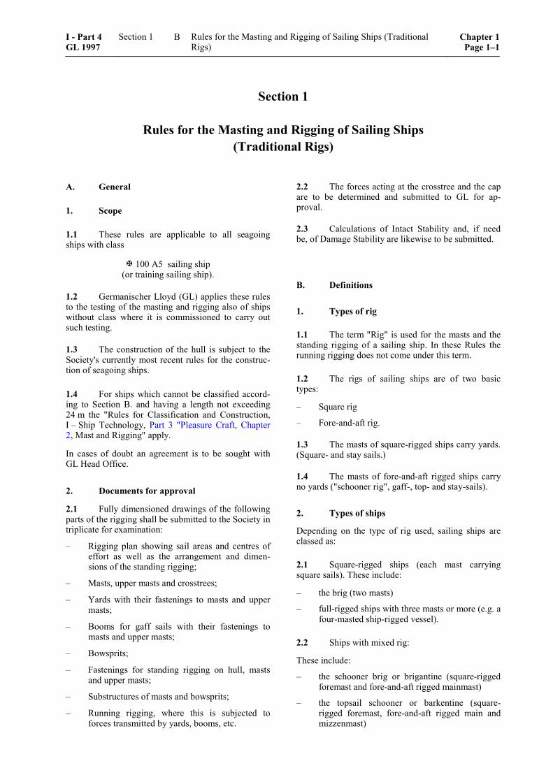
1.1 These rules are applicable to all seagoing ships with class
100 A5 sailing ship (or training sailing ship).
1.2 Germanischer Lloyd (GL) applies these rules to the testing of the masting and rigging also of ships without class where it is commissioned to carry out such testing.
1.3 The construction of the hull is subject to the Society's currently most recent rules for the construc-tion of seagoing ships.
1.4 For ships which cannot be classified accord-ing to Section B. and having a length not exceeding 24 m the "Rules for Classification and Construction, I – Ship Technology, Part 3 "Pleasure Craft, Chapter 2, Mast and Rigging" apply.
In cases of doubt an agreement is to be sought with GL Head Office.
2. Documents for approval
2.1 Fully dimensioned drawings of the following parts of the rigging shall be submitted to the Society in triplicate for examination:
– Rigging plan showing sail areas and centres of effort as well as the arrangement and dimen-sions of the standing rigging;
– Masts, upper masts and crosstrees;
– Yards with their fastenings to masts and upper masts;
– Booms for gaff sails with their fastenings to masts and upper masts;
– Bowsprits;
– Fastenings for standing rigging on hull, masts and upper masts;
– Substructures of masts and bowsprits;
– Running rigging, where this is subjected to forces transmitted by yards, booms, etc.
2.2 The forces acting at the crosstree and the cap are to be determined and submitted to GL for ap-proval.
2.3 Calculations of Intact Stability and, if need be, of Damage Stability are likewise to be submitted.
B. Definitions
1. Types of rig
1.1 The term "Rig" is used for the masts and the standing rigging of a sailing ship. In these Rules the running rigging does not come under this term.
1.2 The rigs of sailing ships are of two basic types:
– Square rig
– Fore-and-aft rig.
1.3 The masts of square-rigged ships carry yards. (Square- and stay sails.)
1.4 The masts of fore-and-aft rigged ships carry no yards ("schooner rig", gaff-, top- and stay-sails).
2. Types of ships
Depending on the type of rig used, sailing ships are classed as:
2.1 Square-rigged ships (each mast carrying square sails). These include:
– the brig (two masts)
– full-rigged ships with three masts or more (e.g. a four-masted ship-rigged vessel).
2.2 Ships with mixed rig:
These include:
– the schooner brig or brigantine (square-rigged foremast and fore-and-aft rigged mainmast)
– the topsail schooner or barkentine (square-rigged foremast, fore-and-aft rigged main and mizzenmast)
I - Part 4 GL 1997
Section 1 Rules for the Masting and Rigging of Sailing Ships (Traditional Rigs)
Chapter 1Page 1–1
B
– the bark (square-rigged fore- and mainmast, fore-and-aft rigged mizzenmast)
– the bark with more than three masts (the after-most mast invariably fore-and-aft riggid)
– the square topsail schooner (masts are both square and fore-and-aft rigged).
2.3 Schooners (fore-and-aft rig only).
These include:
– the two-masted schooner
– the fore-and-aft schooner with three or more masts (e.g. a five-masted schooner).
3. Nomenclature applied to masts
3.1 Different names are given to the masts on the various types of vessel. The following terms are used:
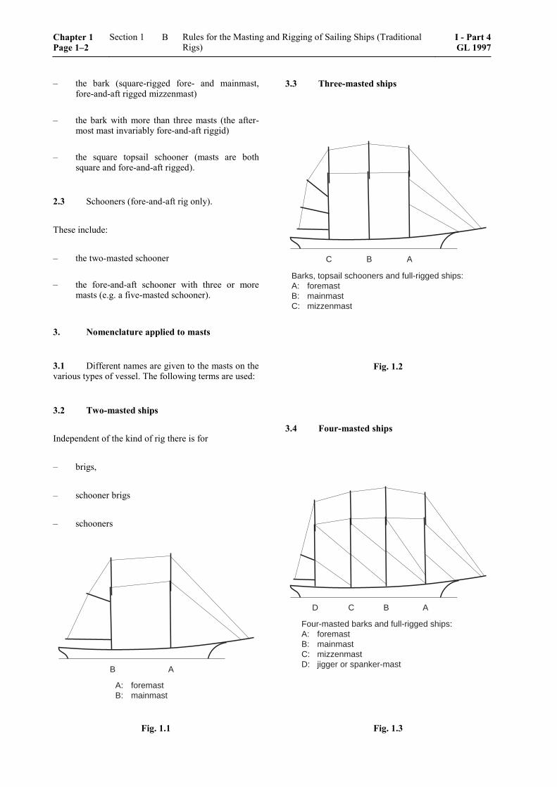
3.2 Two-masted ships
Independent of the kind of rig there is for
– brigs,
– schooner brigs
– schooners
B A
A: foremastB: mainmast
Fig. 1.1
3.3 Three-masted ships
B AC
Barks, topsail schooners and full-rigged ships:A: foremastB: mainmastC: mizzenmast
Fig. 1.2
3.4 Four-masted ships
AC BD
Four-masted barks and full-rigged ships:A: foremastB: mainmastC: mizzenmastD: jigger or spanker-mast
Fig. 1.3
Chapter 1 Page 1–2
Section 1 Rules for the Masting and Rigging of Sailing Ships (Traditional Rigs)
I - Part 4GL 1997
B
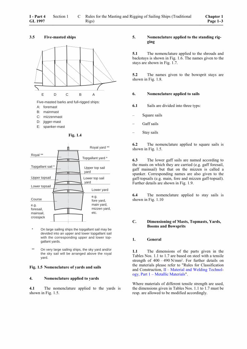
3.5 Five-masted ships
AC BE D
Five-masted barks and full-rigged ships:A: foremastB: mainmastC: mizzenmastD: jigger-mastE: spanker-mast
Fig. 1.4
Lower yard
Lower top sail yard
Upper top sailyard
Topgallant yard *
Royal yard **
Course
Lower topsail
Upper topsail
Topgallant sail *
Royal **
e.g.foresail,mainsail,crossjack
e.g.fore yard,main yard,mizzen yard,etc.
* On large sailing ships the topgallant sail may bedevided into an upper and lower topgallant sailwith the corresponding upper and lower top-gallant yards.
** On very large sailing ships, the sky yard and/orthe sky sail will be arranged above the royalyard.
Fig. 1.5 Nomenclature of yards and sails
4. Nomenclature applied to yards
4.1 The nomenclature applied to the yards is shown in Fig. 1.5.
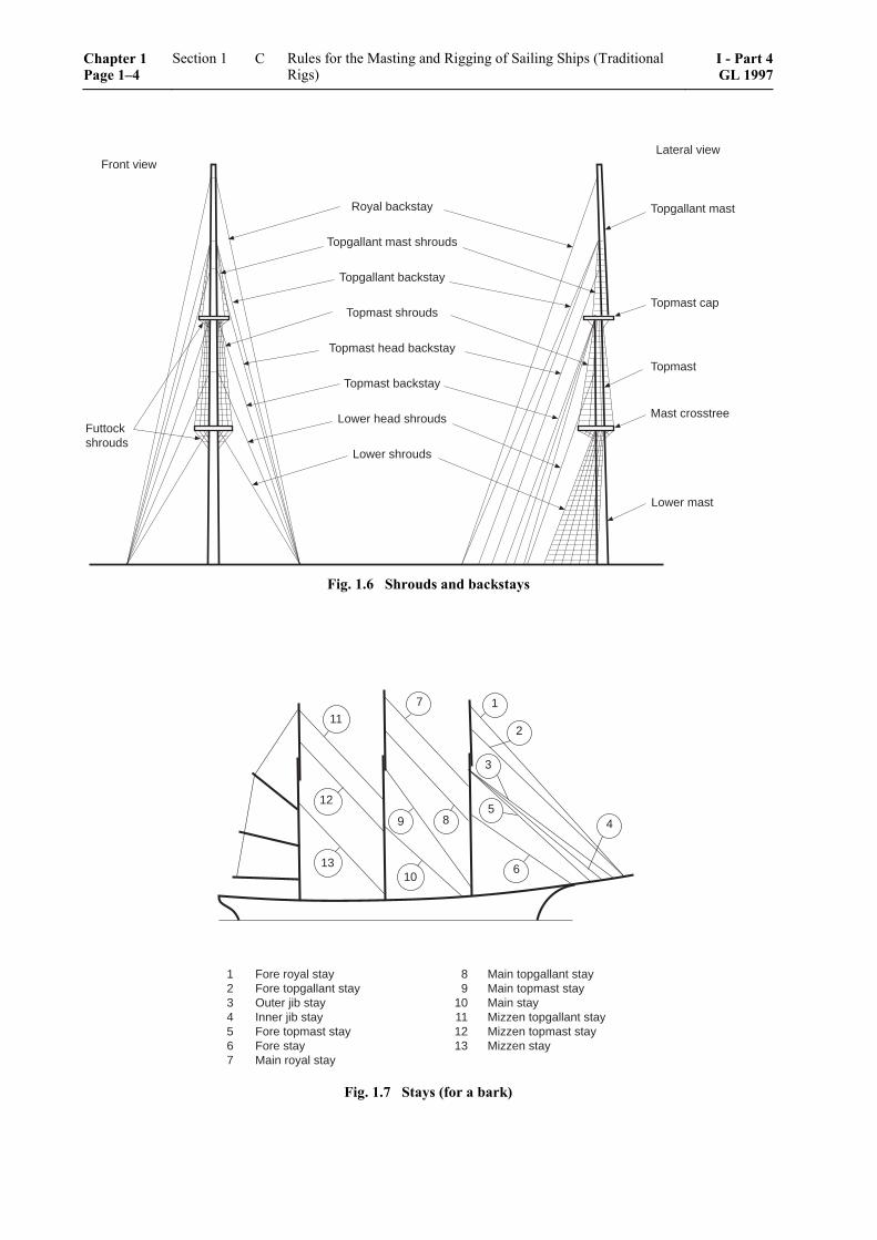
5. Nomenclature applied to the standing rig-ging
5.1 The nomenclature applied to the shrouds and backstays is shown in Fig. 1.6. The names given to the stays are shown in Fig. 1.7.
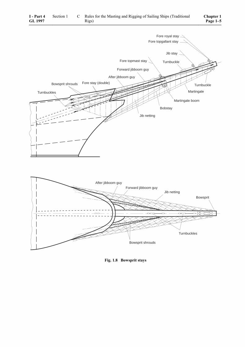
5.2 The names given to the bowsprit stays are shown in Fig. 1.8.
6. Nomenclature applied to sails
6.1 Sails are divided into three typs:
– Square sails
– Gaff sails
– Stay sails
6.2 The nomenclature applied to square sails is shown in Fig. 1.5.
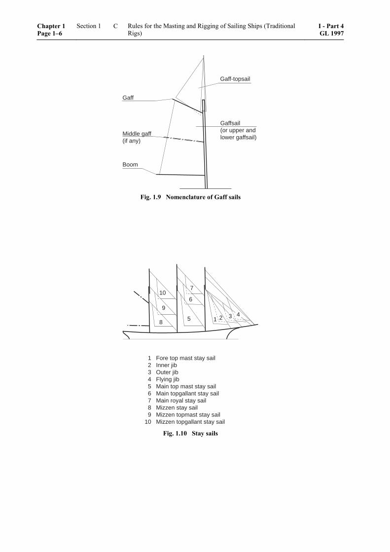
6.3 The lower gaff sails are named according to the masts on which they are carried (e.g. gaff foresail, gaff mainsail) but that on the mizzen is called a spanker. Corresponding names are also given to the gaff-topsails (e.g. main, fore and mizzen gaff-topsail). Further details are shown in Fig. 1.9.
6.4 The nomenclature applied to stay sails is shown in Fig. 1.10
C. Dimensioning of Masts, Topmasts, Yards, Booms and Bowsprits
1. General
1.1 The dimensions of the parts given in the Tables Nos. 1.1 to 1.7 are based on steel with a tensile strength of 400 – 490 N/mm2. For further details on the materials please refer to "Rules for Classification and Construction, II – Material and Welding Technol-ogy, Part 1 – Metallic Materials".
Where materials of different tensile strength are used, the dimensions given in Tables Nos. 1.1 to 1.7 must be resp. are allowed to be modified accordingly.
I - Part 4 GL 1997
Section 1 Rules for the Masting and Rigging of Sailing Ships (Traditional Rigs)
Chapter 1Page 1–3
C
Front view
Futtockshrouds
Lateral view
Topgallant mast
Topmast cap
Topmast
Mast crosstree
Lower mast
Royal backstay
Topgallant mast shrouds
Topgallant backstay
Topmast shrouds
Topmast head backstay
Topmast backstay
Lower head shrouds
Lower shrouds
Fig. 1.6 Shrouds and backstays
7
89
1
2
3
5
6
4
1013
12
11
1 Fore royal stay 8 Main topgallant stay2 Fore topgallant stay 9 Main topmast stay3 Outer jib stay 10 Main stay4 Inner jib stay 11 Mizzen topgallant stay5 Fore topmast stay 12 Mizzen topmast stay6 Fore stay 13 Mizzen stay7 Main royal stay
Fig. 1.7 Stays (for a bark)
Chapter 1 Page 1–4
Section 1 Rules for the Masting and Rigging of Sailing Ships (Traditional Rigs)
I - Part 4GL 1997
C
After jibboom guy
Forward jibboom guy
Fore stay (double)Bowsprit shrouds
Turnbuckles
Jib netting
Fore topmast stay
Jib stay
Turnbuckle
Fore royal stay
Fore topgallant stay
Turnbuckle
Martingale
Martingale boom
Bobstay
After jibboom guy
Forward jibboom guyJib netting
Bowsprit
Turnbuckles
Bowsprit shrouds
Fig. 1.8 Bowsprit stays
I - Part 4 GL 1997
Section 1 Rules for the Masting and Rigging of Sailing Ships (Traditional Rigs)
Chapter 1Page 1–5
C
Gaff-topsail
Gaff
Middle gaff(if any)
Boom
Gaffsail(or upper andlower gaffsail)
Fig. 1.9 Nomenclature of Gaff sails
7
8
10
1 25
6
943
1 Fore top mast stay sail2 Inner jib3 Outer jib4 Flying jib5 Main top mast stay sail6 Main topgallant stay sail7 Main royal stay sail8 Mizzen stay sail9 Mizzen topmast stay sail
10 Mizzen topgallant stay sail
Fig. 1.10 Stay sails
Chapter 1 Page 1–6
Section 1 Rules for the Masting and Rigging of Sailing Ships (Traditional Rigs)
I - Part 4GL 1997
C
1.2 If solid spars are used they get the same di-ameters as specified in the text or Tables depending on their kind of use. This is based on the characteristic values of comparatively light woods as fire and spruce.
The max. diameter of wooden masts, upper masts, yards, booms or bowsprits may be reduced by 10 % if they are made from pitch pine or oregon pine, and by 5 % if they are made from pine or larch. The other diameters are then to be taken from the respective line in the Tables 1.1 to 1.7.
All spars must be of best condition, sufficiently dried, sound and free from sap, branches and detrimental faults. Timber of twisted growth may not be used.
2. Masts
2.1 Length and dimensions of masts
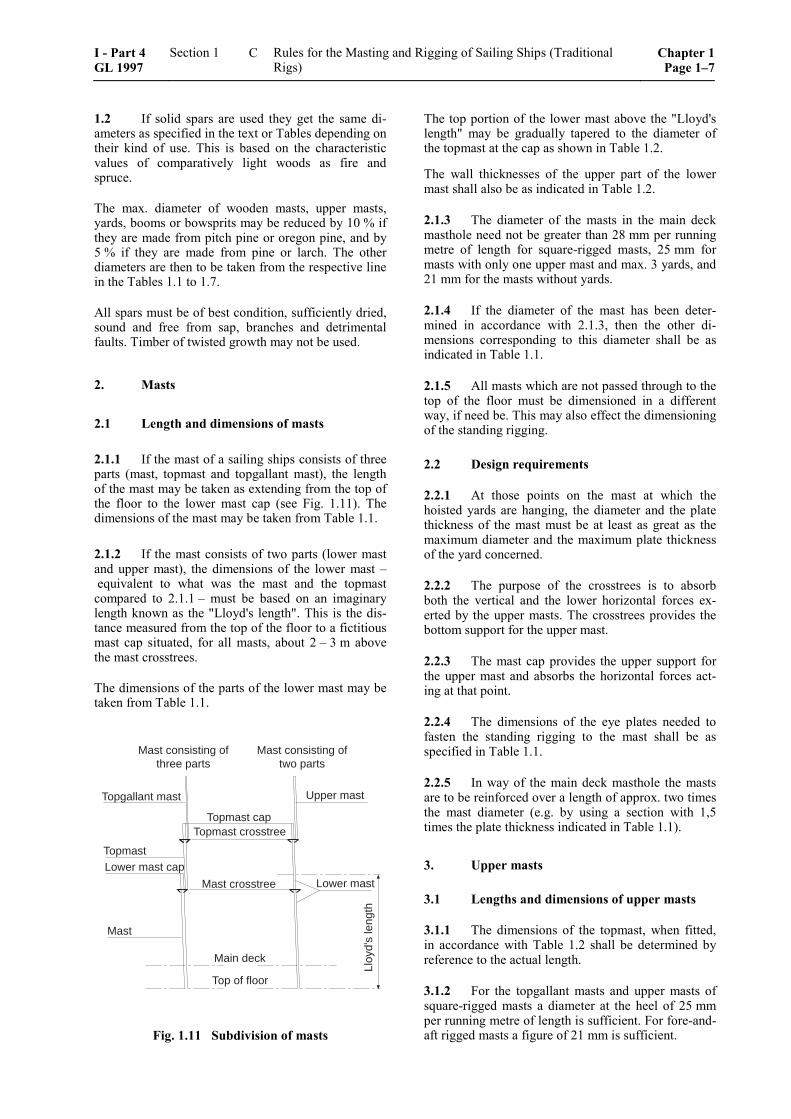
2.1.1 If the mast of a sailing ships consists of three parts (mast, topmast and topgallant mast), the length of the mast may be taken as extending from the top of the floor to the lower mast cap (see Fig. 1.11). The dimensions of the mast may be taken from Table 1.1.
2.1.2 If the mast consists of two parts (lower mast and upper mast), the dimensions of the lower mast – equivalent to what was the mast and the topmast compared to 2.1.1 – must be based on an imaginary length known as the "Lloyd's length". This is the dis-tance measured from the top of the floor to a fictitious mast cap situated, for all masts, about 2 – 3 m above the mast crosstrees.
The dimensions of the parts of the lower mast may be taken from Table 1.1.
Topmast capTopmast crosstree
Mast crosstree
Main deck
Top of floor
Topgallant mast
TopmastLower mast cap
Mast
Upper mast
Lower mast
Lloy
d's
leng
th
Mast consisting ofthree parts
Mast consisting oftwo parts
Fig. 1.11 Subdivision of masts
The top portion of the lower mast above the "Lloyd's length" may be gradually tapered to the diameter of the topmast at the cap as shown in Table 1.2.
The wall thicknesses of the upper part of the lower mast shall also be as indicated in Table 1.2.
2.1.3 The diameter of the masts in the main deck masthole need not be greater than 28 mm per running metre of length for square-rigged masts, 25 mm for masts with only one upper mast and max. 3 yards, and 21 mm for the masts without yards.
2.1.4 If the diameter of the mast has been deter-mined in accordance with 2.1.3, then the other di-mensions corresponding to this diameter shall be as indicated in Table 1.1.
2.1.5 All masts which are not passed through to the top of the floor must be dimensioned in a different way, if need be. This may also effect the dimensioning of the standing rigging.
2.2 Design requirements
2.2.1 At those points on the mast at which the hoisted yards are hanging, the diameter and the plate thickness of the mast must be at least as great as the maximum diameter and the maximum plate thickness of the yard concerned.
2.2.2 The purpose of the crosstrees is to absorb both the vertical and the lower horizontal forces ex-erted by the upper masts. The crosstrees provides the bottom support for the upper mast.
2.2.3 The mast cap provides the upper support for the upper mast and absorbs the horizontal forces act-ing at that point.
2.2.4 The dimensions of the eye plates needed to fasten the standing rigging to the mast shall be as specified in Table 1.1.
2.2.5 In way of the main deck masthole the masts are to be reinforced over a length of approx. two times the mast diameter (e.g. by using a section with 1,5 times the plate thickness indicated in Table 1.1).
3. Upper masts
3.1 Lengths and dimensions of upper masts
3.1.1 The dimensions of the topmast, when fitted, in accordance with Table 1.2 shall be determined by reference to the actual length.
3.1.2 For the topgallant masts and upper masts of square-rigged masts a diameter at the heel of 25 mm per running metre of length is sufficient. For fore-and-aft rigged masts a figure of 21 mm is sufficient.
I - Part 4 GL 1997
Section 1 Rules for the Masting and Rigging of Sailing Ships (Traditional Rigs)
Chapter 1Page 1–7
C
3.1.3 If the diameter of the topgallant mast and the upper mast at the heel has been determined according to 3.1.2 all other dimensions shall be those shown in Table 1.2 for this diameter.
3.2 Design requirements
3.2.1 Upper masts are to be reinforced at the cap, the crosstrees and the sheave-holes (e.g. by using a section having 1.5 times the plate thickness specified in Table 1.2).
3.2.2 At those points on upper masts at which the hoisted yards are hanging, the diameter and the plate thickness of the upper mast must be at least as great as the maximum diameter and the maximum plate thick-ness of the yard concerned.
4. Bowsprit
4.1 Use and dimensions of the bowsprit
4.1.1 The bowsprit is used to secure the lower ends of the various foremast stays (see Fig. 1.8).
4.1.2 The dimensions of the bowsprit shall be those shown in Table 1.7.
4.1.3 The dimensions of the bob stay and bowsprit shrouds shall be those shown in Table 1.8.
4.1.4 The following relationships are also appli-cable:
– Diameter of the martin gale = 0,6 × diameter of the bob stay
– Diameter of the martin gale boom = 1,15 × diameter of the bob stay
4.2 Design requirements
4.2.1 The distance between the housing at the heel of the bowsprit and the housing at the stem must be at least 4 times the diameter of the bowsprit.
4.2.2 At the bowsprit, strong horses and hand beck-ets as well as a sufficient number of cross ropes or nets must be fitted. Ships exceeding 700 GRT must be provided with nets underneath their bowsprits, ex-tending up to the forecastle.
4.2.3 The bowsprit is to be reinforced within the housings (e.g. by using a section having 1,5 times the plate thickness specified in Table 1.7).
5. Yards
5.1 Dimensions of yards
5.1.1 The dimensions of yards shall be those in-dicated in Table 1.4.
5.1.2 The diameter in the middle need not exceed 19 mm per running metre for topgallant yards or 18 mm per running metre for royal yards.
5.1.3 If the diameter in the middle has been deter-mined in accordance with 5.1.2, the other dimensions shall be those shown in Table 1.4 for this diameter.
5.2 Arrangement of yards
5.2.1 Yards may be fixed to the mast or adjustable in hight.
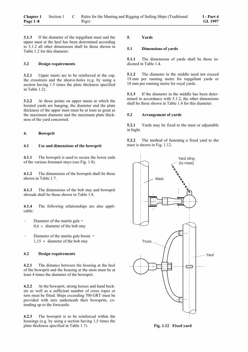
5.2.2 The method of fastening a fixed yard to the mast is shown in Fig. 1.12.
Mast
Yard sling(to mast)
Truss
Yard
Fig. 1.12 Fixed yard
Chapter 1 Page 1–8
Section 1 Rules for the Masting and Rigging of Sailing Ships (Traditional Rigs)
I - Part 4GL 1997
C
The yard sling is designed to support and transmit to the mast the vertical force (structural weight and wind pressure component) acting on the yard. It transmits this force to the mast and/or the upper mast.
The required load of the yard sling shall be that speci-fied in Table 1.5.
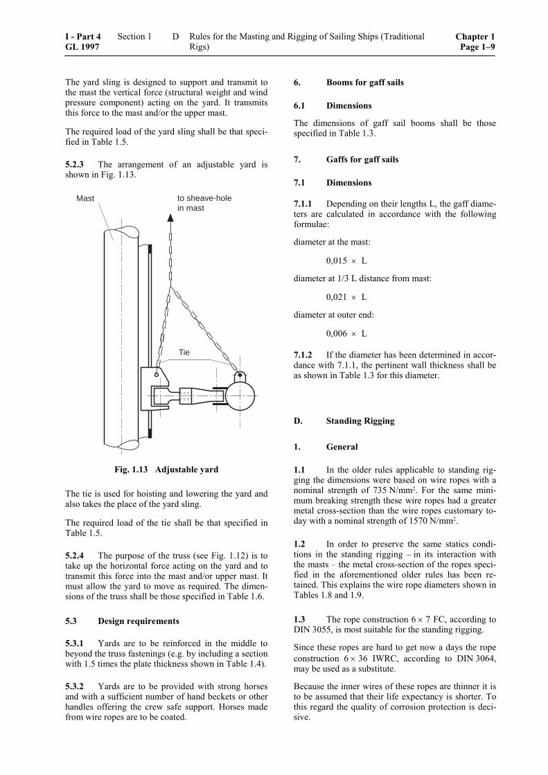
5.2.3 The arrangement of an adjustable yard is shown in Fig. 1.13.
Mast
Tie
to sheave-holein mast
Fig. 1.13 Adjustable yard
The tie is used for hoisting and lowering the yard and also takes the place of the yard sling.
The required load of the tie shall be that specified in Table 1.5.
5.2.4 The purpose of the truss (see Fig. 1.12) is to take up the horizontal force acting on the yard and to transmit this force into the mast and/or upper mast. It must allow the yard to move as required. The dimen-sions of the truss shall be those specified in Table 1.6.
5.3 Design requirements
5.3.1 Yards are to be reinforced in the middle to beyond the truss fastenings (e.g. by including a section with 1.5 times the plate thickness shown in Table 1.4).
5.3.2 Yards are to be provided with strong horses and with a sufficient number of hand beckets or other handles offering the crew safe support. Horses made from wire ropes are to be coated.
6. Booms for gaff sails
6.1 Dimensions
The dimensions of gaff sail booms shall be those specified in Table 1.3.
7. Gaffs for gaff sails
7.1 Dimensions
7.1.1 Depending on their lengths L, the gaff diame-ters are calculated in accordance with the following formulae:
diameter at the mast:
0,015 × L
diameter at 1/3 L distance from mast:
0,021 × L
diameter at outer end:
0,006 × L
7.1.2 If the diameter has been determined in accor-dance with 7.1.1, the pertinent wall thickness shall be as shown in Table 1.3 for this diameter.
D. Standing Rigging
1. General
1.1 In the older rules applicable to standing rig-ging the dimensions were based on wire ropes with a nominal strength of 735 N/mm2. For the same mini-mum breaking strength these wire ropes had a greater metal cross-section than the wire ropes customary to-day with a nominal strength of 1570 N/mm2.
1.2 In order to preserve the same statics condi-tions in the standing rigging – in its interaction with the masts – the metal cross-section of the ropes speci-fied in the aforementioned older rules has been re-tained. This explains the wire rope diameters shown in Tables 1.8 and 1.9.
1.3 The rope construction 6 × 7 FC, according to DIN 3055, is most suitable for the standing rigging.
Since these ropes are hard to get now a days the rope construction 6 × 36 IWRC, according to DIN 3064, may be used as a substitute.
Because the inner wires of these ropes are thinner it is to be assumed that their life expectancy is shorter. To this regard the quality of corrosion protection is deci-sive.
I - Part 4 GL 1997
Section 1 Rules for the Masting and Rigging of Sailing Ships (Traditional Rigs)
Chapter 1Page 1–9
D
1.4 Ropes of the construction type 6 × 19 FC, according to DIN 3060, have a bigger elasticity than those referred to under 1.3. Apart from having to choose a comparatively bigger diameter (see footnote in the Tables 1.8 and 1.9) the adjustability may be increased, if need be, by using links which can be removed later on.
2. Dimensions of standing rigging
2.1 The dimensions of standing rigging and its fastenings shall be those specified in Tables 1.8 to 1.16.
2.2 For the square-rigged masts of four and five-masted ships, the diameter of the standing rigging may be reduced according to the statements in Table 1.8.
2.3 For full-rigged ships and barks, the length of the masts – except for the aftermost mast – may be taken as the average of the individual mast lengths, and the beam at the main deck may be taken as the average of the deck breadths at the individual masts for determination of the dimensions of the standing rigging.
2.4 Where masts less than 24 m long carry dou-ble topgallant yards, a topmast head backstay shall also be fitted to the topmast cap.
2.5 If the angle made by the bob stay and bow-sprit shrouds with the centre line of the bowsprit is less than 14°, then the bob stay and bowsprit shrouds shall be strengthened accordingly (see Fig. 1.8).
2.6 The dimensions of the turnbuckles are shown in Tables 1.12 to 1.15.
2.7 The dimensions of the other parts of the fas-tenings may be determined by reference to the effec-tive Lifting Appliances Regulations. Their loads shall match those of the corresponding turnbuckles.
3. Design requirements
3.1 Where shrouds are fixed to the mast by shackles, a separate shackle and eye is required for each shroud.
3.2 Wherever possible, standing rigging shall be fixed directly to the sheer strake.
3.3 Where sail-carrying stays (e.g. those fastened to the bowsprit) are led around guide sheaves, the diameters of Keep the guide sheaves must be equal to at least 5 times the nominal diameter of the stay con-cerned.
3.4 Stays shall be arranged in such a way that the forces are properly transmitted between the masts.
3.5 The futtock shrouds may also be constructed in the form of round steel bars.
E. Miscellaneous
1. Components
1.1 Interchangeable components
1.1.1 Where not specified in the Tables, the di-mensions of these components shall be determined in accordance with the loads imposed on them by ref-erence to the effective Lifting Appliances Regulations.
1.1.2 It is not necessary to test each component under load. The testing of randomly selected samples using the standard test loads according to the Lifting Appliances Regulations is sufficient. The scope of the tests shall be determined by the Surveyor responsible. In any event, not less than 20 % of all components should be tested.
1.1.3 Para. 1.1.2 does not apply if the ship owner requires more extensive tests.
1.2 Non-interchangeable components
These components like for instance bearings and eye plates shall be dealt with in accordance with the effec-tive Lifting Appliance Regulations.
1.3 Nominal sizes
The nominal sizes of components according to the Tables 1.11 to 1.15 are to be choosen dependent on the related wire rope diameter according to Table 1.16.
2. Running rigging
2.1 Only those parts of the running rigging form part of the classification to which forces are transmit-ted by the structural components covered by Sections C. and D.
2.2 For running rigging, both fibre ropes (natural or synthetic fibres) and steel wire ropes may be used.
2.3 Running rigging shall be designed to the satisfaction of the Surveyor responsible.
Chapter 1 Page 1–10
Section 1 Rules for the Masting and Rigging of Sailing Ships (Traditional Rigs)
I - Part 4GL 1997
E
3. Spare parts
3.1 On voyages in International Service each sailing ship must carry on board a spar suitable for a uppermast or lower yard and a second spar suitable for a jibboom or topsail yard.
Ships with schooner rig and sailing ships engaged in Restricted International Service need carry only one spare spar on board. If they have an engine of suffi-cient power, this spare spar is not required.
3.2 It is recommended that, in addition to the above, enough further spare spars be carried to allow one spar for each mast.
3.3 It is further recommended that each vessel carries along a sufficient reserve for the running rig-ging.
3.4 For sailing vessels the following spare sails are required.
Five-masted full rigged shipsFive-masted barks and
four-masted full rigged shipsFour-masted barks,
full-rigged ships and barks
3 lower sails3 lower topsails3 upper topsails1 fore topmast stay sail1 jib1 mizzen stays sail
or1 storm mizzen
2 lower sails3 lower topsails2 upper topsails1 fore topmast stay sail1 jib1 mizzen stay sail
or1 storm mizzen
1 foresail1 lower topsail1 upper topsail1 fore topmast stay sail1 jib1 mizzen stay sail
or1 storm mizzen
Barkentines, schooner briggs,three-masted schooners with yards
Square topsail shooners andfore and aft schooners Smaller vessels without yards
1 foresail1 topsail1 fore topmast stay sail1 jib1 main stay sail1 mainsail
1 fore stay sail1 jumbo 2
1 boom foresail 1
1 jumbo 2
1 mainsail 1
1 Jib-like head sail.2 For sailing vessels equipped with sufficiently powerful engines navigating in the North Sea and the Baltic, the boom foresail and
the mainsail are not required.
I - Part 4 GL 1997
Section 1 Rules for the Masting and Rigging of Sailing Ships (Traditional Rigs)
Chapter 1Page 1–11
E
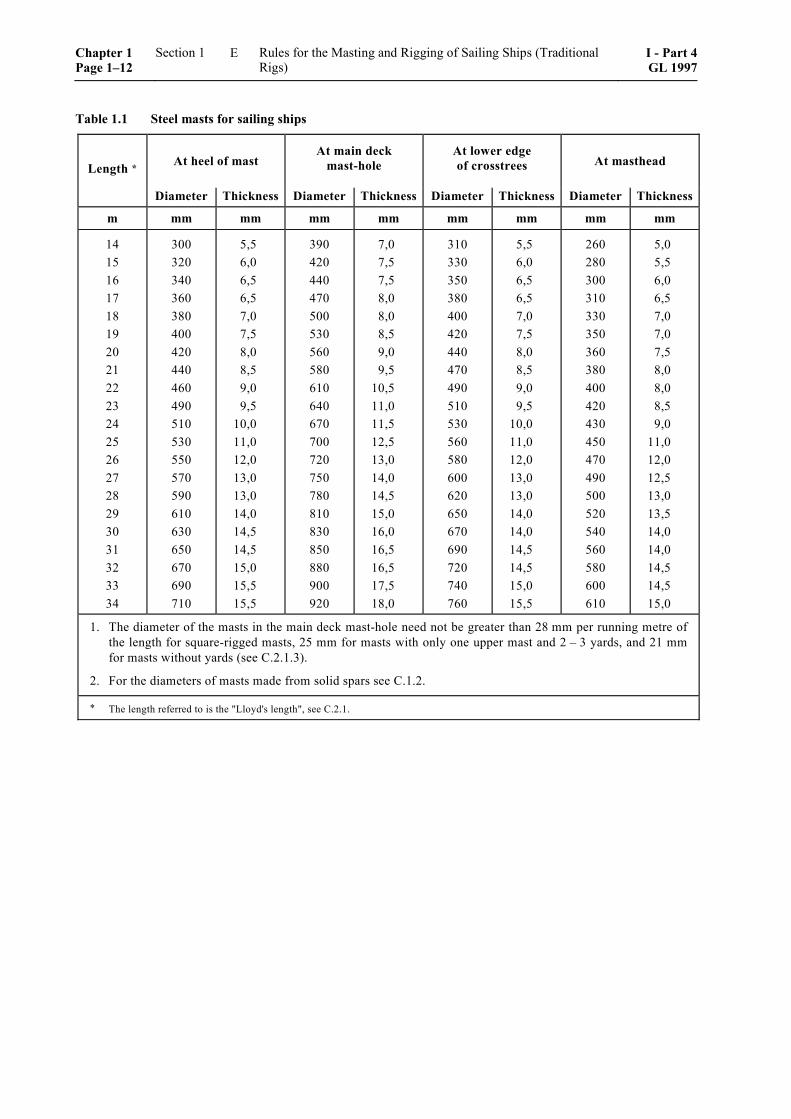
Table 1.1 Steel masts for sailing ships
Length * At heel of mastAt main deck
mast-holeAt lower edgeof crosstrees At masthead
Diameter Thickness Diameter Thickness Diameter Thickness Diameter Thickness
m mm mm mm mm mm mm mm mm
141516171819202122232425262728293031323334
300320340360380400420440460490510530550570590610630650670690710
5,56,06,56,57,07,58,08,59,09,5
10,011,012,013,013,014,014,514,515,015,515,5
390420440470500530560580610640670700720750780810830850880900920
7,07,57,58,08,08,59,09,5
10,511,011,512,513,014,014,515,016,016,516,517,518,0
310330350380400420440470490510530560580600620650670690720740760
5,56,06,56,57,07,58,08,59,09,5
10,011,012,013,013,014,014,014,514,515,015,5
260280300310330350360380400420430450470490500520540560580600610
5,05,56,06,57,07,07,58,08,08,59,0
11,012,012,513,013,514,014,014,514,515,0
1. The diameter of the masts in the main deck mast-hole need not be greater than 28 mm per running metre ofthe length for square-rigged masts, 25 mm for masts with only one upper mast and 2 – 3 yards, and 21 mmfor masts without yards (see C.2.1.3).
2. For the diameters of masts made from solid spars see C.1.2.
* The length referred to is the "Lloyd's length", see C.2.1.
Chapter 1 Page 1–12
Section 1 Rules for the Masting and Rigging of Sailing Ships (Traditional Rigs)
I - Part 4GL 1997
E
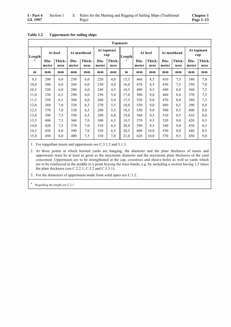
Table 1.2 Uppermasts for sailing ships
Topmasts
LengthAt heel At masthead
At topmastcap Length
At heel At mastheadAt topmast
cap* Dia-
meterThick-
nessDia-
meterThick-
nessDia-
meterThick-
ness* Dia-
meterThick-
nessDia-
meterThick-
nessDia-
meterThick-
ness
m mm mm mm mm mm mm m mm mm mm mm mm mm
9,510,010,511,011,512,012,513,013,514,014,515,0
290300320330350360370390400420430450
6,06,06,06,56,57,07,07,57,57,58,08,0
250260280290300320330350360370390400
6,06,06,06,06,06,56,56,57,07,07,07,5
220230240250260270280290300310320330
4,04,04,55,05,05,55,56,06,56,56,57,0
15,516,016,517,017,518,018,519,019,520,020,521,0
460470490500520530550560570590600620
8,58,58,59,09,09,09,09,59,59,5
10,010,0
410430440460470480500510520540550570
7,57,58,08,08,08,58,58,59,09,09,09,5
340350360370380390400410420430440450
7,07,07,57,57,58,08,08,08,58,58,59,0
1. For topgallant masts and uppermasts see C.3.1.2 and 3.1.3.
2. At those points at which hoisted yards are hanging, the diameter and the plate thickness of masts anduppermasts must be at least as great as the maximum diameter and the maximum plate thickness of the yardconcerned. Uppermasts are to be strengthened at the cap, crosstrees and sheave-holes as well as yards whichare to be reinforced in the middle to a point beyong the truss bands, e.g. by including a section having 1,5 timesthe plate thickness (see C.2.2.1, C.3.2 and C.5.3.1).
3. For the diameters of uppermasts made from solid spars see C.1.2.
* Regarding the length see C.2.1
I - Part 4 GL 1997
Section 1 Rules for the Masting and Rigging of Sailing Ships (Traditional Rigs)
Chapter 1Page 1–13
E
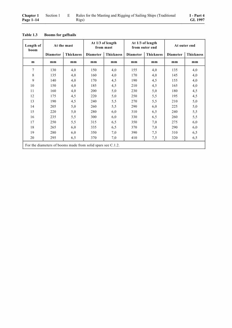
Table 1.3 Booms for gaffsails
Length ofboom
At the mastAt 1/3 of length
from mastAt 1/3 of lengthfrom outer end At outer end
Diameter Thickness Diameter Thickness Diameter Thickness Diameter Thickness
m mm mm mm mm mm mm mm mm
789
1011121314151617181920
130135140150160175190205220235250265280295
4,04,04,04,04,04,54,55,05,05,55,56,06,06,5
150160170185200220240260280300315335350370
4,04,04,54,55,05,05,55,56,06,06,56,57,07,0
155170190210230250270290310330350370390410
4,04,04,54,55,05,55,56,06,56,57,07,07,57,5
135145155165180195210225240260275290310320
4,04,04,04,04,54,55,05,05,55,56,06,06,56,5
For the diameters of booms made from solid spars see C.1.2.
Chapter 1 Page 1–14
Section 1 Rules for the Masting and Rigging of Sailing Ships (Traditional Rigs)
I - Part 4GL 1997
E
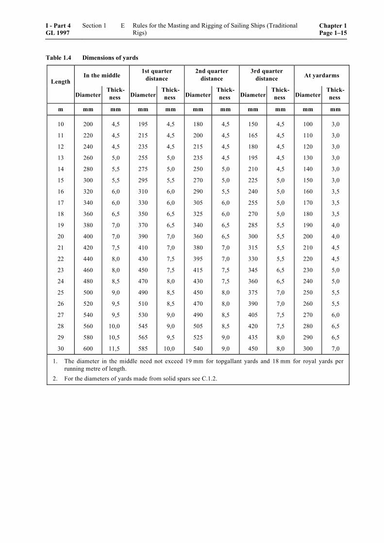
Table 1.4 Dimensions of yards
LengthIn the middle
1st quarterdistance
2nd quarterdistance
3rd quarterdistance At yardarms
DiameterThick-ness Diameter
Thick-ness Diameter
Thick-ness Diameter
Thick-ness Diameter
Thick-ness
m mm mm mm mm mm mm mm mm mm mm
10
11
12
13
14
15
16
17
18
19
20
21
22
23
24
25
26
27
28
29
30
200
220
240
260
280
300
320
340
360
380
400
420
440
460
480
500
520
540
560
580
600
4,5
4,5
4,5
5,0
5,5
5,5
6,0
6,0
6,5
7,0
7,0
7,5
8,0
8,0
8,5
9,0
9,5
9,5
10,0
10,5
11,5
195
215
235
255
275
295
310
330
350
370
390
410
430
450
470
490
510
530
545
565
585
4,5
4,5
4,5
5,0
5,0
5,5
6,0
6,0
6,5
6,5
7,0
7,0
7,5
7,5
8,0
8,5
8,5
9,0
9,0
9,5
10,0
180
200
215
235
250
270
290
305
325
340
360
380
395
415
430
450
470
490
505
525
540
4,5
4,5
4,5
4,5
5,0
5,0
5,5
6,0
6,0
6,5
6,5
7,0
7,0
7,5
7,5
8,0
8,0
8,5
8,5
9,0
9,0
150
165
180
195
210
225
240
255
270
285
300
315
330
345
360
375
390
405
420
435
450
4,5
4,5
4,5
4,5
4,5
5,0
5,0
5,0
5,0
5,5
5,5
5,5
5,5
6,5
6,5
7,0
7,0
7,5
7,5
8,0
8,0
100
110
120
130
140
150
160
170
180
190
200
210
220
230
240
250
260
270
280
290
300
3,0
3,0
3,0
3,0
3,0
3,0
3,5
3,5
3,5
4,0
4,0
4,5
4,5
5,0
5,0
5,5
5,5
6,0
6,5
6,5
7,0
1. The diameter in the middle need not exceed 19 mm for topgallant yards and 18 mm for royal yards perrunning metre of length.
2. For the diameters of yards made from solid spars see C.1.2.
I - Part 4 GL 1997
Section 1 Rules for the Masting and Rigging of Sailing Ships (Traditional Rigs)
Chapter 1Page 1–15
E
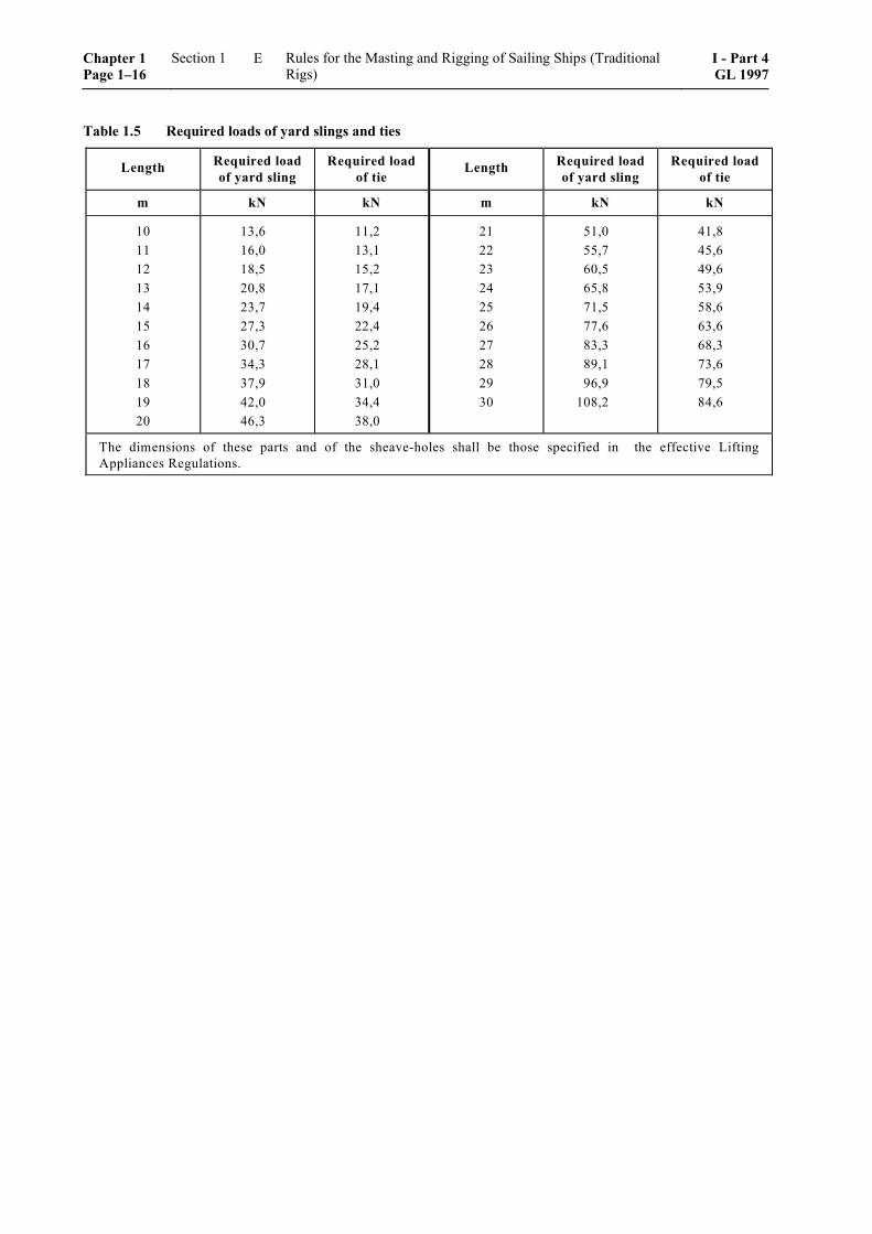
Table 1.5 Required loads of yard slings and ties
Length Required loadof yard sling
Required loadof tie
Length Required loadof yard sling
Required loadof tie
m kN kN m kN kN
1011121314151617181920
13,616,018,520,823,727,330,734,337,942,046,3
11,213,115,217,119,422,425,228,131,034,438,0
21222324252627282930
51,055,760,565,871,577,683,389,196,9
108,2
41,845,649,653,958,663,668,373,679,584,6
The dimensions of these parts and of the sheave-holes shall be those specified in the effective LiftingAppliances Regulations.
Chapter 1 Page 1–16
Section 1 Rules for the Masting and Rigging of Sailing Ships (Traditional Rigs)
I - Part 4GL 1997
E
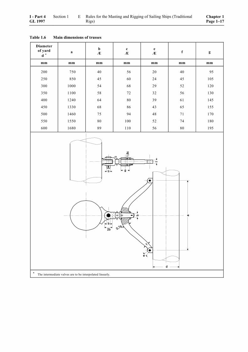
Table 1.6 Main dimensions of trusses
Diameter of yard
d * a
b Æ
c Æ
e Æ f g
mm mm mm mm mm mm mm
200
250
300
350
400
450
500
550
600
750
850
1000
1100
1240
1330
1460
1550
1680
40
45
54
58
64
68
75
80
89
56
60
68
72
80
86
94
100
110
20
24
29
32
39
43
48
52
56
40
45
52
56
61
65
71
74
80
95
105
120
130
145
155
170
180
195
* The intermediate valves are to be interpolated linearly.
I - Part 4 GL 1997
Section 1 Rules for the Masting and Rigging of Sailing Ships (Traditional Rigs)
Chapter 1Page 1–17
E
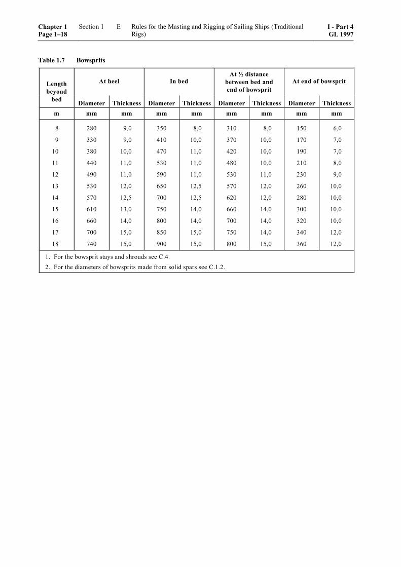
Table 1.7 Bowsprits
Lengthbeyond
At heel In bedAt ½ distance
between bed andend of bowsprit
At end of bowsprit
bed Diameter Thickness Diameter Thickness Diameter Thickness Diameter Thicknessm mm mm mm mm mm mm mm mm
8
9
10
11
12
13
14
15
16
17
18
280
330
380
440
490
530
570
610
660
700
740
9,0
9,0
10,0
11,0
11,0
12,0
12,5
13,0
14,0
15,0
15,0
350
410
470
530
590
650
700
750
800
850
900
8,0
10,0
11,0
11,0
11,0
12,5
12,5
14,0
14,0
15,0
15,0
310
370
420
480
530
570
620
660
700
750
800
8,0
10,0
10,0
10,0
11,0
12,0
12,0
14,0
14,0
14,0
15,0
150
170
190
210
230
260
280
300
320
340
360
6,0
7,0
7,0
8,0
9,0
10,0
10,0
10,0
10,0
12,0
12,0
1. For the bowsprit stays and shrouds see C.4.2. For the diameters of bowsprits made from solid spars see C.1.2.
Chapter 1 Page 1–18
Section 1 Rules for the Masting and Rigging of Sailing Ships (Traditional Rigs)
I - Part 4GL 1997
E
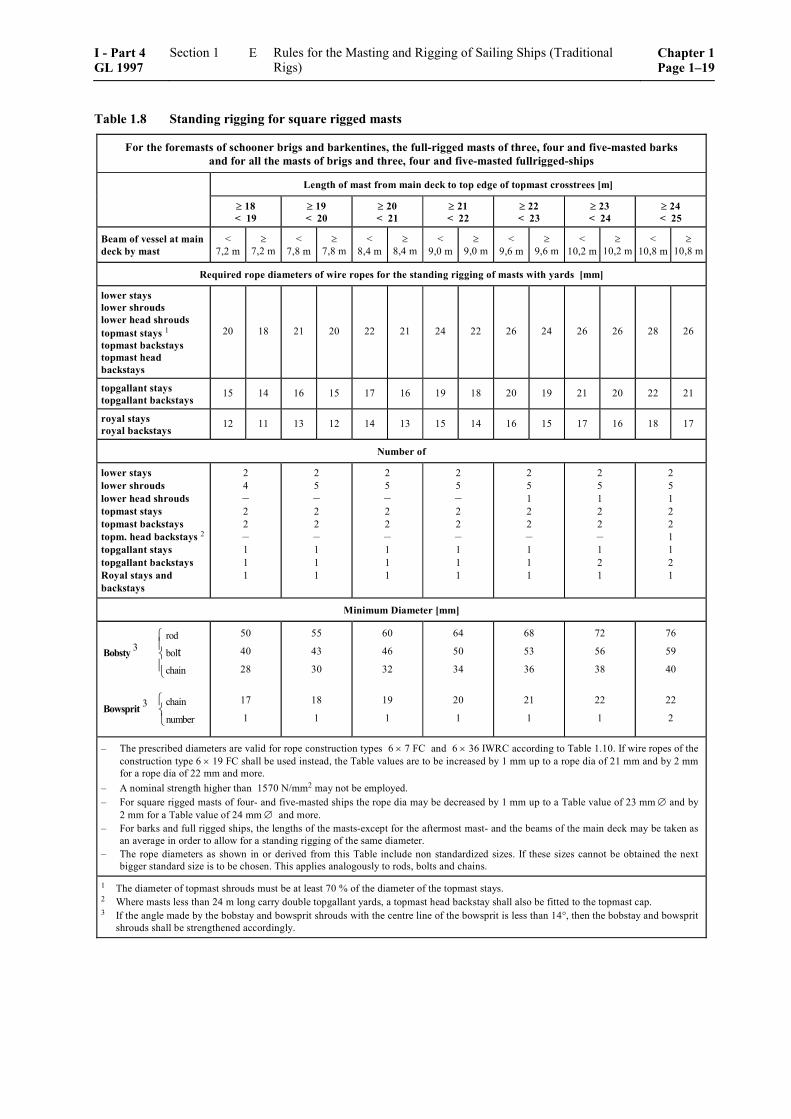
Table 1.8 Standing rigging for square rigged masts
For the foremasts of schooner brigs and barkentines, the full-rigged masts of three, four and five-masted barks and for all the masts of brigs and three, four and five-masted fullrigged-ships
Length of mast from main deck to top edge of topmast crosstrees [m]
≥ 18 < 19
≥ 19 < 20
≥ 20 < 21
≥ 21 < 22
≥ 22 < 23
≥ 23 < 24
≥ 24 < 25
Beam of vessel at main deck by mast
< 7,2 m
≥ 7,2 m
< 7,8 m
≥ 7,8 m
< 8,4 m
≥ 8,4 m
< 9,0 m
≥ 9,0 m
< 9,6 m
≥ 9,6 m
< 10,2 m
≥ 10,2 m
< 10,8 m
≥ 10,8 m
Required rope diameters of wire ropes for the standing rigging of masts with yards [mm]
lower stays lower shrouds lower head shrouds topmast stays 1 topmast backstays topmast head backstays
20 18 21 20 22 21 24 22 26 24 26 26 28 26
topgallant stays topgallant backstays
15 14 16 15 17 16 19 18 20 19 21 20 22 21
royal stays royal backstays
12 11 13 12 14 13 15 14 16 15 17 16 18 17
Number of
lower stays lower shrouds lower head shrouds topmast stays topmast backstays topm. head backstays 2
topgallant stays topgallant backstays Royal stays and backstays
2 4 – 2 2 – 1 1 1
2 5 – 2 2 – 1 1 1
2 5 – 2 2 – 1 1 1
2 5 – 2 2 – 1 1 1
2 5 1 2 2 – 1 1 1
2 5 1 2 2 – 1 2 1
2 5 1 2 2 1 1 2 1
Minimum Diameter [mm]
rod3 bol
chain
t⎧⎪⎨⎪⎩
Bobsty
chain3number
⎧⎨⎩
Bowsprit
50
40
28
17
1
55
43
30
18
1
60
46
32
19
1
64
50
34
20
1
68
53
36
21
1
72
56
38
22
1
76
59
40
22
2
– The prescribed diameters are valid for rope construction types 6 × 7 FC and 6 × 36 IWRC according to Table 1.10. If wire ropes of the construction type 6 × 19 FC shall be used instead, the Table values are to be increased by 1 mm up to a rope dia of 21 mm and by 2 mm for a rope dia of 22 mm and more.
– A nominal strength higher than 1570 N/mm2 may not be employed. – For square rigged masts of four- and five-masted ships the rope dia may be decreased by 1 mm up to a Table value of 23 mm ∅ and by
2 mm for a Table value of 24 mm ∅ and more. – For barks and full rigged ships, the lengths of the masts-except for the aftermost mast- and the beams of the main deck may be taken as
an average in order to allow for a standing rigging of the same diameter. – The rope diameters as shown in or derived from this Table include non standardized sizes. If these sizes cannot be obtained the next
bigger standard size is to be chosen. This applies analogously to rods, bolts and chains.
1 The diameter of topmast shrouds must be at least 70 % of the diameter of the topmast stays. 2 Where masts less than 24 m long carry double topgallant yards, a topmast head backstay shall also be fitted to the topmast cap. 3 If the angle made by the bobstay and bowsprit shrouds with the centre line of the bowsprit is less than 14°, then the bobstay and bowsprit
shrouds shall be strengthened accordingly.
I - Part 4 GL 1997
Section 1 Rules for the Masting and Rigging of Sailing Ships (Traditional Rigs)
Chapter 1Page 1–19
E
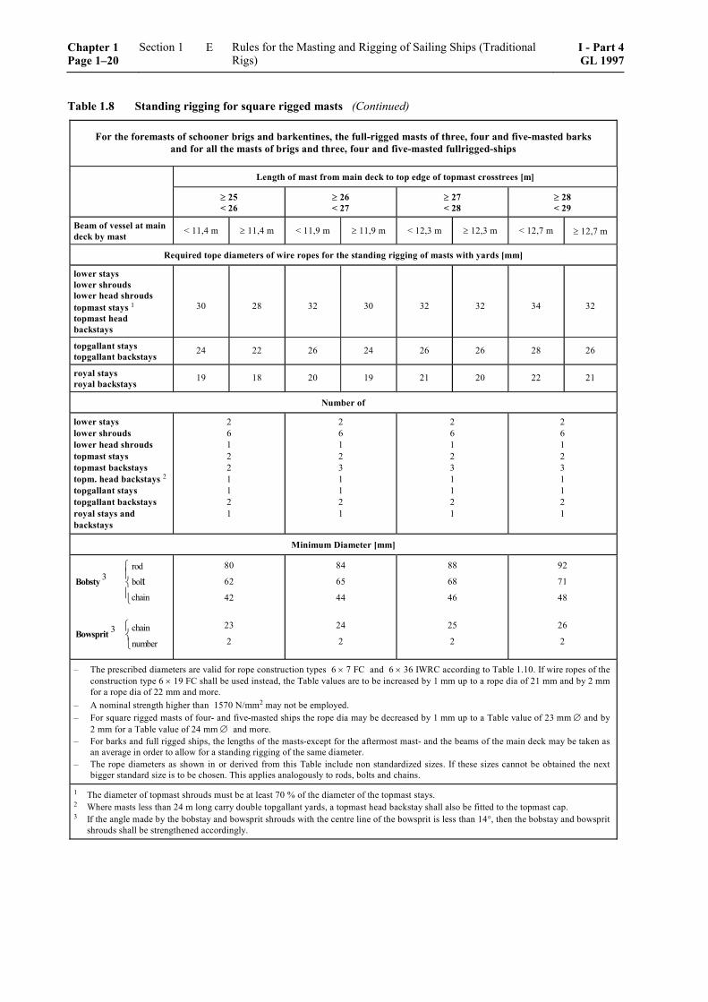
Table 1.8 Standing rigging for square rigged masts (Continued)
For the foremasts of schooner brigs and barkentines, the full-rigged masts of three, four and five-masted barks and for all the masts of brigs and three, four and five-masted fullrigged-ships
Length of mast from main deck to top edge of topmast crosstrees [m]
≥ 25 < 26
≥ 26 < 27
≥ 27 < 28
≥ 28 < 29
Beam of vessel at main deck by mast < 11,4 m ≥ 11,4 m < 11,9 m ≥ 11,9 m < 12,3 m ≥ 12,3 m < 12,7 m ≥ 12,7 m
Required tope diameters of wire ropes for the standing rigging of masts with yards [mm]
lower stays lower shrouds lower head shrouds topmast stays 1 topmast head backstays
30 28 32 30 32 32 34 32
topgallant stays topgallant backstays 24 22 26 24 26 26 28 26
royal stays royal backstays 19 18 20 19 21 20 22 21
Number of
lower stays lower shrouds lower head shrouds topmast stays topmast backstays topm. head backstays 2
topgallant stays topgallant backstays royal stays and backstays
2 6 1 2 2 1 1 2 1
2 6 1 2 3 1 1 2 1
2 6 1 2 3 1 1 2 1
2 6 1 2 3 1 1 2 1
Minimum Diameter [mm]
rod3 bol
chain
t⎧⎪⎨⎪⎩
Bobsty
chain3number
⎧⎨⎩
Bowsprit
80
62
42
23
2
84
65
44
24
2
88
68
46
25
2
92
71
48
26
2
– The prescribed diameters are valid for rope construction types 6 × 7 FC and 6 × 36 IWRC according to Table 1.10. If wire ropes of the construction type 6 × 19 FC shall be used instead, the Table values are to be increased by 1 mm up to a rope dia of 21 mm and by 2 mm for a rope dia of 22 mm and more.
– A nominal strength higher than 1570 N/mm2 may not be employed. – For square rigged masts of four- and five-masted ships the rope dia may be decreased by 1 mm up to a Table value of 23 mm ∅ and by
2 mm for a Table value of 24 mm ∅ and more. – For barks and full rigged ships, the lengths of the masts-except for the aftermost mast- and the beams of the main deck may be taken as
an average in order to allow for a standing rigging of the same diameter. – The rope diameters as shown in or derived from this Table include non standardized sizes. If these sizes cannot be obtained the next
bigger standard size is to be chosen. This applies analogously to rods, bolts and chains.
1 The diameter of topmast shrouds must be at least 70 % of the diameter of the topmast stays. 2 Where masts less than 24 m long carry double topgallant yards, a topmast head backstay shall also be fitted to the topmast cap. 3 If the angle made by the bobstay and bowsprit shrouds with the centre line of the bowsprit is less than 14°, then the bobstay and bowsprit
shrouds shall be strengthened accordingly.
Chapter 1 Page 1–20
Section 1 Rules for the Masting and Rigging of Sailing Ships (Traditional Rigs)
I - Part 4GL 1997
E
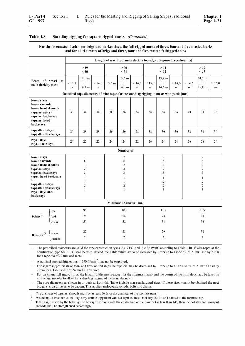
Table 1.8 Standing rigging for square rigged masts (Continued)
For the foremasts of schooner brigs and barkentines, the full-rigged masts of three, four and five-masted barks and for all the masts of brigs and three, four and five-masted fullrigged-ships
Length of mast from main deck to top edge of topmast crosstrees [m]
≥ 29 < 30
≥ 30 < 31
≥ 31 < 32
≥ 32 < 33
Beam of vessel at main deck by mast < 13,1
m
13,1 m –
14,0 m > 14,0
m 13,5 m
13,5 m–
14,3 m > 14,3
m < 13,9
m
13,9 m–
14,6 m > 14,6
m < 14,3
m
14,3 m –
15,0 m > 15,0
m
Required rope diameters of wire ropes for the standing rigging of masts with yards [mm]
lower stays lower shrouds lower head shrouds topmast stays 1 topmast backstays topmast head backstays
36 34 34 38 36 34 38 38 36 40 38 38
topgallant stays topgallant backstays 30 28 28 30 30 28 32 30 30 32 32 30
royal stays royal backstays 24 22 22 24 24 22 26 24 24 26 26 24
Number of
lower stays lower shrouds lower head shrouds topmast stays topmast backstays topm. head backstays 2 topgallant stays topgallant backstays royal stays and backstays
2 6 1 2 3 1 1 2 1
2 6 2 2 3 1 1 2 1
2 6 2 2 3 1 2 2 1
2 6 2 2 3 1 2 2 1
Minimum Diameter [mm]
rod3 bol
chain
t⎧⎪⎨⎪⎩
Bobsty
chain3number
⎧⎨⎩
Bowsprit
96
74
50
27
2
100
76
52
28
2
103
78
54
29
2
105
80
56
30
2
– The prescribed diameters are valid for rope construction types 6 × 7 FC and 6 × 36 IWRC according to Table 1.10. If wire ropes of the construction type 6 × 19 FC shall be used instead, the Table values are to be increased by 1 mm up to a rope dia of 21 mm and by 2 mm for a rope dia of 22 mm and more.
– A nominal strength higher than 1570 N/mm2 may not be employed. – For square rigged masts of four- and five-masted ships the rope dia may be decreased by 1 mm up to a Table value of 23 mm ∅ and by
2 mm for a Table value of 24 mm ∅ and more. – For barks and full rigged ships, the lengths of the masts-except for the aftermost mast- and the beams of the main deck may be taken as
an average in order to allow for a standing rigging of the same diameter. – The rope diameters as shown in or derived from this Table include non standardized sizes. If these sizes cannot be obtained the next
bigger standard size is to be chosen. This applies analogously to rods, bolts and chains.
1 The diameter of topmast shrouds must be at least 70 % of the diameter of the topmast stays. 2 Where masts less than 24 m long carry double topgallant yards, a topmast head backstay shall also be fitted to the topmast cap. 3 If the angle made by the bobstay and bowsprit shrouds with the centre line of the bowsprit is less than 14°, then the bobstay and bowsprit
shrouds shall be strengthened accordingly.
I - Part 4 GL 1997
Section 1 Rules for the Masting and Rigging of Sailing Ships (Traditional Rigs)
Chapter 1Page 1–21
E
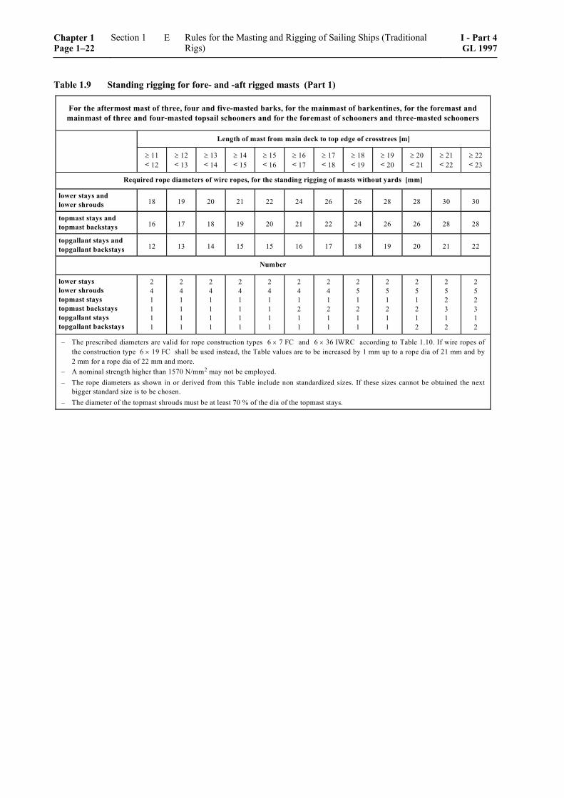
Table 1.9 Standing rigging for fore- and -aft rigged masts (Part 1)
For the aftermost mast of three, four and five-masted barks, for the mainmast of barkentines, for the foremast andmainmast of three and four-masted topsail schooners and for the foremast of schooners and three-masted schooners
Length of mast from main deck to top edge of crosstrees [m]
≥ 11< 12
≥ 12< 13
≥ 13< 14
≥ 14< 15
≥ 15< 16
≥ 16< 17
≥ 17< 18
≥ 18< 19
≥ 19< 20
≥ 20< 21
≥ 21< 22
≥ 22< 23
Required rope diameters of wire ropes, for the standing rigging of masts without yards [mm]
lower stays andlower shrouds 18 19 20 21 22 24 26 26 28 28 30 30
topmast stays andtopmast backstays 16 17 18 19 20 21 22 24 26 26 28 28
topgallant stays andtopgallant backstays 12 13 14 15 15 16 17 18 19 20 21 22
Number
lower stayslower shroudstopmast staystopmast backstaystopgallant staystopgallant backstays
241111
241111
241111
241111
241111
241211
241211
251211
251211
251212
252312
252312
– The prescribed diameters are valid for rope construction types 6 × 7 FC and 6 × 36 IWRC according to Table 1.10. If wire ropes ofthe construction type 6 × 19 FC shall be used instead, the Table values are to be increased by 1 mm up to a rope dia of 21 mm and by2 mm for a rope dia of 22 mm and more.
– A nominal strength higher than 1570 N/mm2 may not be employed.– The rope diameters as shown in or derived from this Table include non standardized sizes. If these sizes cannot be obtained the next
bigger standard size is to be chosen.– The diameter of the topmast shrouds must be at least 70 % of the dia of the topmast stays.
Chapter 1 Page 1–22
Section 1 Rules for the Masting and Rigging of Sailing Ships (Traditional Rigs)
I - Part 4GL 1997
E
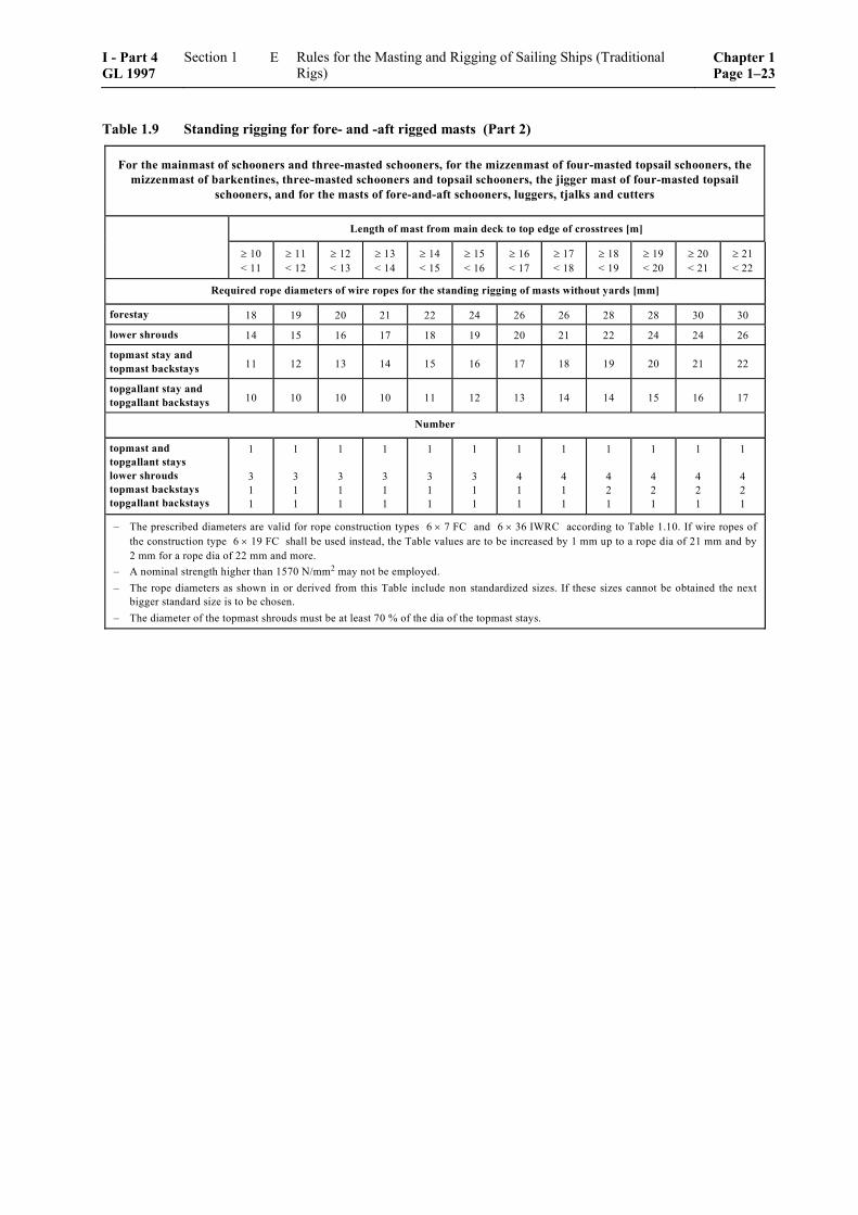
Table 1.9 Standing rigging for fore- and -aft rigged masts (Part 2)
For the mainmast of schooners and three-masted schooners, for the mizzenmast of four-masted topsail schooners, themizzenmast of barkentines, three-masted schooners and topsail schooners, the jigger mast of four-masted topsail
schooners, and for the masts of fore-and-aft schooners, luggers, tjalks and cutters
Length of mast from main deck to top edge of crosstrees [m]
≥ 10< 11
≥ 11< 12
≥ 12< 13
≥ 13< 14
≥ 14< 15
≥ 15< 16
≥ 16< 17
≥ 17< 18
≥ 18< 19
≥ 19< 20
≥ 20< 21
≥ 21< 22
Required rope diameters of wire ropes for the standing rigging of masts without yards [mm]
forestay 18 19 20 21 22 24 26 26 28 28 30 30
lower shrouds 14 15 16 17 18 19 20 21 22 24 24 26
topmast stay andtopmast backstays 11 12 13 14 15 16 17 18 19 20 21 22
topgallant stay andtopgallant backstays 10 10 10 10 11 12 13 14 14 15 16 17
Number
topmast andtopgallant stayslower shroudstopmast backstaystopgallant backstays
1
311
1
311
1
311
1
311
1
311
1
311
1
411
1
411
1
421
1
421
1
421
1
421
– The prescribed diameters are valid for rope construction types 6 × 7 FC and 6 × 36 IWRC according to Table 1.10. If wire ropes ofthe construction type 6 × 19 FC shall be used instead, the Table values are to be increased by 1 mm up to a rope dia of 21 mm and by2 mm for a rope dia of 22 mm and more.
– A nominal strength higher than 1570 N/mm2 may not be employed.– The rope diameters as shown in or derived from this Table include non standardized sizes. If these sizes cannot be obtained the next
bigger standard size is to be chosen.– The diameter of the topmast shrouds must be at least 70 % of the dia of the topmast stays.
I - Part 4 GL 1997
Section 1 Rules for the Masting and Rigging of Sailing Ships (Traditional Rigs)
Chapter 1Page 1–23
E
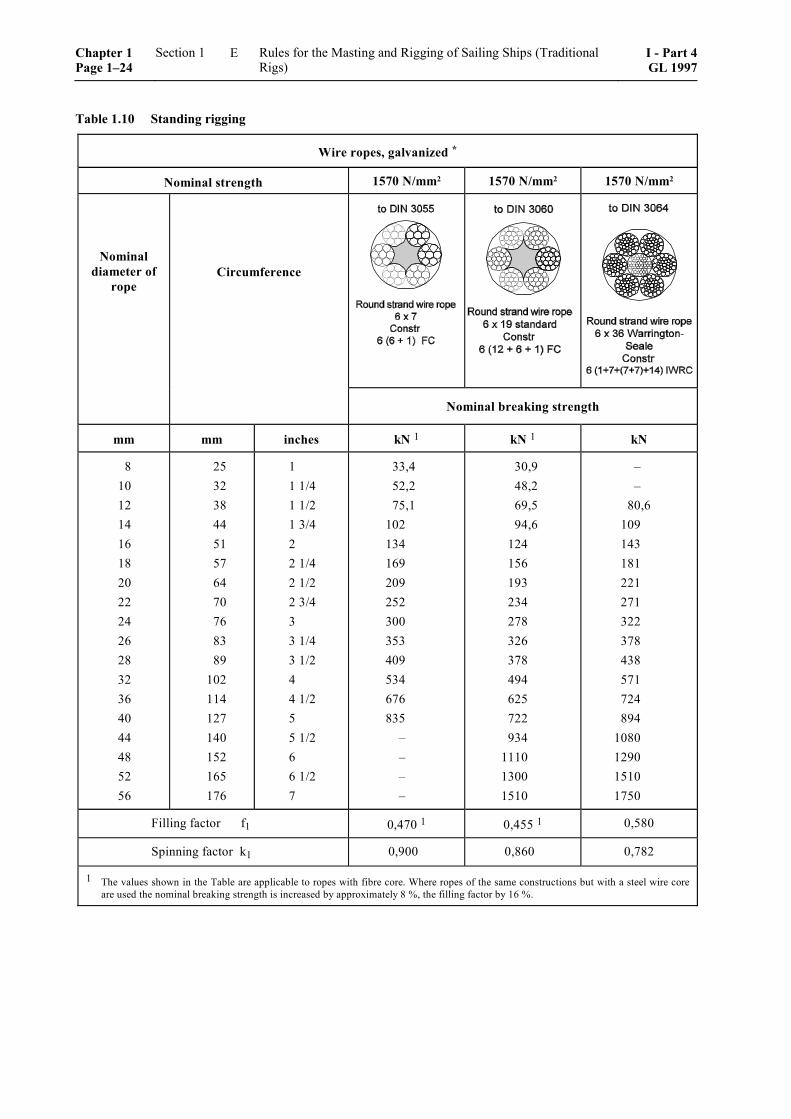
Table 1.10 Standing rigging
Wire ropes, galvanized *
Nominal strength 1570 N/mm2 1570 N/mm2 1570 N/mm2
Nominal diameter of
rope Circumference
Nominal breaking strength
mm mm inches kN 1 kN 1 kN
8 10 12 14 16 18 20 22 24 26 28 32 36 40 44 48 52 56
25 32 38 44 51 57 64 70 76 83 89 102 114 127 140 152 165 176
1 1 1/4 1 1/2 1 3/4 2 2 1/4 2 1/2 2 3/4 3 3 1/4 3 1/2 4 4 1/2 5 5 1/2 6 6 1/2 7
33,4 52,2 75,1
102 134 169 209 252 300 353 409 534 676 835
– – – –
30,9 48,2 69,5 94,6
124 156 193 234 278 326 378 494 625 722 934
1110 1300 1510
– –
80,6 109 143 181 221 271 322 378 438 571 724 894
1080 1290 1510 1750
Filling factor f1 0,470 1 0,455 1 0,580
Spinning factor k1 0,900 0,860 0,782
1 The values shown in the Table are applicable to ropes with fibre core. Where ropes of the same constructions but with a steel wire core are used the nominal breaking strength is increased by approximately 8 %, the filling factor by 16 %.
Chapter 1 Page 1–24
Section 1 Rules for the Masting and Rigging of Sailing Ships (Traditional Rigs)
I - Part 4GL 1997
E

Table 1.11 Eyes and double-lugs for tensile loads acc. to ISO 6043
Nominal size 1
Permitted load b1 b2 b3 d2 d3 r1 r2 t
Bolt s1
Fillet weld
d1 thread a
KN mm mm mm mm mm mm mm mm mm mm mm
1 1,6 2 2,5 3 4 5 6 8
10 12
10 16 20 25 32 40 50 63 80
100 125
16 20 22 25 28 30 35 40 45 50 55
19 23 26 29 32 35 39 45 49 58 64
8 11 12 13 14 15 18 20 23 26 28
18 22 24 26 30 33 39 42 48 52 56
17 21 23 25 28 31 37 40 46 50 54
17,522,525 27,530 32,537,542,547,555 60
5 5 6 6 6 6 8 8 8 8 10
23 28 31 34 36 39 46 51 56 63 70
16 20 22 24 27 30 36 39 45 48 52
M 12 M 16 M 20 M 20 M 22 M 24 M 27 M 30 M 36 M 39 M 42
– 6 6 8 8 8 10 10 12 14 14
– 4 4 5 5 5 6 6 7 7 8
Weldable material with a tensile strength of at least 360 N/mm2. Min. bolt strength = 410 N/mm2
1 Nominal size depending on the related wire rope diameter acc. to Table 1.16.
I - Part 4 GL 1997
Section 1 Rules for the Masting and Rigging of Sailing Ships (Traditional Rigs)
Chapter 1Page 1–25
E
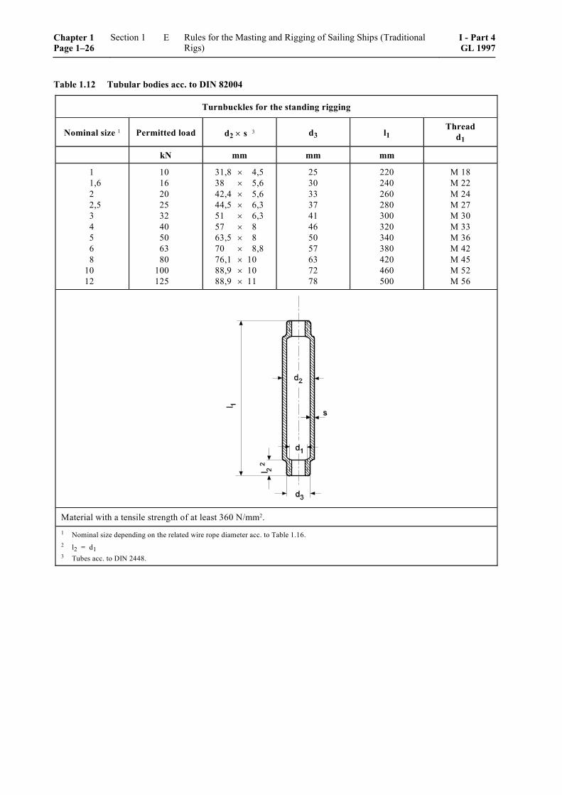
Table 1.12 Tubular bodies acc. to DIN 82004
Turnbuckles for the standing rigging
Nominal size 1 Permitted load d2 × s 3 d3 l1 Thread
d1
kN mm mm mm
1 1,6 2 2,5 3 4 5 6 8
10 12
10 16 20 25 32 40 50 63 80
100 125
31,8 × 4,5 38 × 5,6 42,4 × 5,6 44,5 × 6,3 51 × 6,3 57 × 8 63,5 × 8 70 × 8,8 76,1 × 10 88,9 × 10 88,9 × 11
25 30 33 37 41 46 50 57 63 72 78
220 240 260 280 300 320 340 380 420 460 500
M 18 M 22 M 24 M 27 M 30 M 33 M 36 M 42 M 45 M 52 M 56
Material with a tensile strength of at least 360 N/mm2. 1 Nominal size depending on the related wire rope diameter acc. to Table 1.16. 2 l2 = d1 3 Tubes acc. to DIN 2448.
Chapter 1 Page 1–26
Section 1 Rules for the Masting and Rigging of Sailing Ships (Traditional Rigs)
I - Part 4GL 1997
E
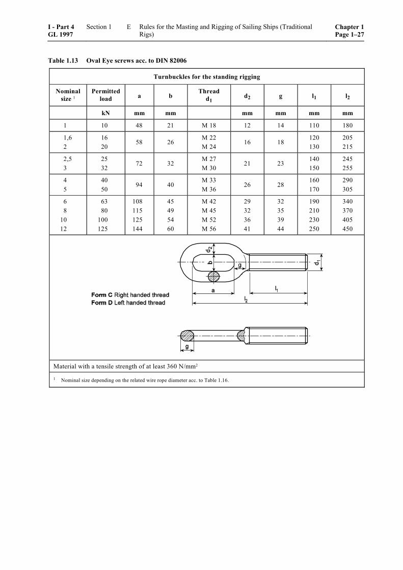
Table 1.13 Oval Eye screws acc. to DIN 82006
Turnbuckles for the standing rigging
Nominal size 1
Permittedload a b
Thread d1 d2 g l1 l2
kN mm mm mm mm mm mm
1 10 48 21 M 18 12 14 110 180
1,6 2
16 20
58 26 M 22 M 24
16 18 120 130
205 215
2,5 3
25 32
72 32 M 27 M 30
21 23 140 150
245 255
4 5
40 50
94 40 M 33 M 36
26 28 160 170
290 305
6 8
10 12
63 80 100 125
108 115 125 144
45 49 54 60
M 42 M 45 M 52 M 56
29 32 36 41
32 35 39 44
190 210 230 250
340 370 405 450
Material with a tensile strength of at least 360 N/mm2
1 Nominal size depending on the related wire rope diameter acc. to Table 1.16.
I - Part 4 GL 1997
Section 1 Rules for the Masting and Rigging of Sailing Ships (Traditional Rigs)
Chapter 1Page 1–27
E
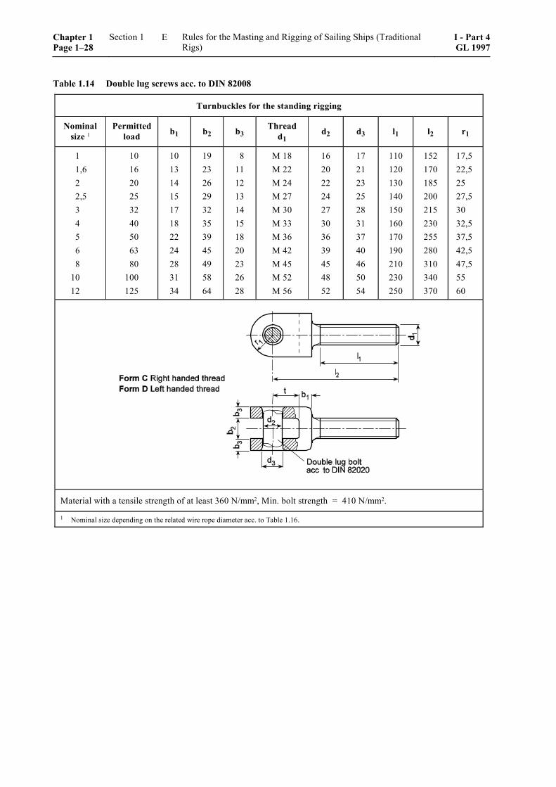
Table 1.14 Double lug screws acc. to DIN 82008
Turnbuckles for the standing rigging
Nominal size 1
Permitted load b1 b2 b3 Thread
d1 d2 d3 l1 l2 r1
1 1,6 2 2,5 3 4 5 6 8
10 12
10 16 20 25 32 40 50 63 80 100 125
10 13 14 15 17 18 22 24 28 31 34
19 23 26 29 32 35 39 45 49 58 64
8 11 12 13 14 15 18 20 23 26 28
M 18 M 22 M 24 M 27 M 30 M 33 M 36 M 42 M 45 M 52 M 56
16 20 22 24 27 30 36 39 45 48 52
17 21 23 25 28 31 37 40 46 50 54
110 120 130 140 150 160 170 190 210 230 250
152 170 185 200 215 230 255 280 310 340 370
17,5 22,5 25 27,5 30 32,5 37,5 42,5 47,5 55 60
Material with a tensile strength of at least 360 N/mm2, Min. bolt strength = 410 N/mm2.
1 Nominal size depending on the related wire rope diameter acc. to Table 1.16.
Chapter 1 Page 1–28
Section 1 Rules for the Masting and Rigging of Sailing Ships (Traditional Rigs)
I - Part 4GL 1997
E
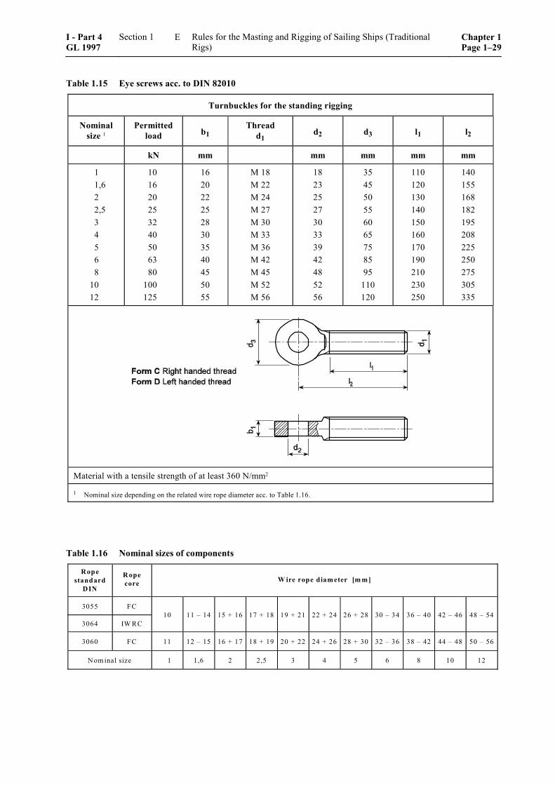
Table 1.15 Eye screws acc. to DIN 82010
Turnbuckles for the standing rigging
Nominal size 1
Permitted load b1
Thread d1 d2 d3 l1 l2
kN mm mm mm mm mm
1 1,6 2 2,5 3 4 5 6 8
10 12
10 16 20 25 32 40 50 63 80 100 125
16 20 22 25 28 30 35 40 45 50 55
M 18 M 22 M 24 M 27 M 30 M 33 M 36 M 42 M 45 M 52 M 56
18 23 25 27 30 33 39 42 48 52 56
35 45 50 55 60 65 75 85 95
110 120
110 120 130 140 150 160 170 190 210 230 250
140 155 168 182 195 208 225 250 275 305 335
Material with a tensile strength of at least 360 N/mm2
1 Nominal size depending on the related wire rope diameter acc. to Table 1.16.
Table 1.16 Nominal sizes of components
Ropestandard
DIN
R opecore W ire rope diam eter [m m ]
3055
3064
FC
IW RC10 11 – 14 15 + 16 17 + 18 19 + 21 22 + 24 26 + 28 30 – 34 36 – 40 42 – 46 48 – 54
3060 FC 11 12 – 15 16 + 17 18 + 19 20 + 22 24 + 26 28 + 30 32 – 36 38 – 42 44 – 48 50 – 56
N om inal size 1 1,6 2 2,5 3 4 5 6 8 10 12
I - Part 4 GL 1997
Section 1 Rules for the Masting and Rigging of Sailing Ships (Traditional Rigs)
Chapter 1Page 1–29
E