Embed Size (px)
Citation preview
Rules for Classification and Construction I Ship Technology
5 Underwater Technology
3 Unmanned Submersibles (ROV, AUV) and Underwater Working Machines Amended 2016-01: Section 1, D of these rules is not applicable for Unmanned Submersibles (ROV, AUV) and Underwater Working Machines transferred to the common DNV GL production system from the date of transfer. For such Unmanned Submersibles (ROV, AUV) and Underwater Working Machines, see DNV GL rules for classification: Underwater technology, Pt.7.
Edition 2009
The following Rules come into force on 1 November 2009.
Germanischer Lloyd Aktiengesellschaft
Head Office Vorsetzen 35, 20459 Hamburg, Germany
Phone: +49 40 36149-0 Fax: +49 40 36149-200
www.gl-group.com
"General Terms and Conditions" of the respective latest edition will be applicable (see Rules for Classification and Construction, I - Ship Technology, Part 0 - Classification and Surveys).
Reproduction by printing or photostatic means is only permissible with the consent of Germanischer Lloyd Aktiengesellschaft.
Published by: Germanischer Lloyd Aktiengesellschaft, Hamburg
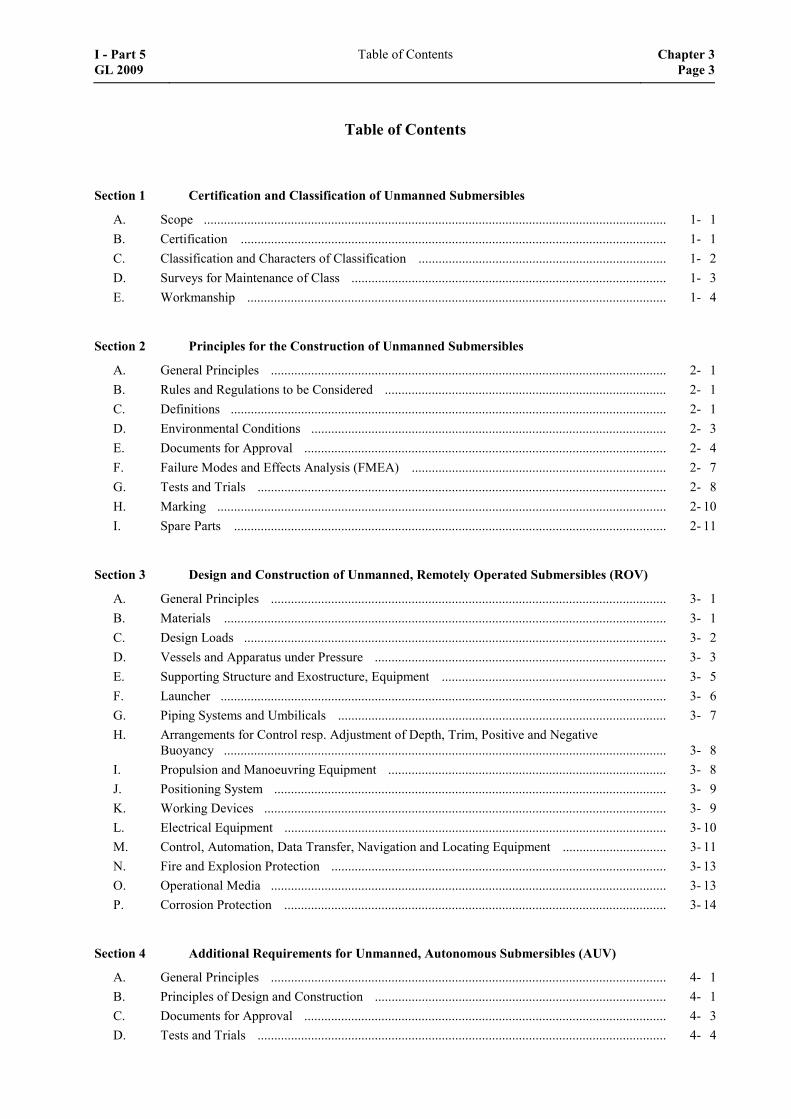
Table of Contents
Section 1 Certification and Classification of Unmanned Submersibles
A. Scope .......................................................................................................................................... 1- 1 B. Certification ............................................................................................................................... 1- 1 C. Classification and Characters of Classification .......................................................................... 1- 2 D. Surveys for Maintenance of Class .............................................................................................. 1- 3 E. Workmanship ............................................................................................................................. 1- 4
Section 2 Principles for the Construction of Unmanned Submersibles
A. General Principles ...................................................................................................................... 2- 1 B. Rules and Regulations to be Considered .................................................................................... 2- 1 C. Definitions .................................................................................................................................. 2- 1 D. Environmental Conditions .......................................................................................................... 2- 3 E. Documents for Approval ............................................................................................................ 2- 4 F. Failure Modes and Effects Analysis (FMEA) ............................................................................ 2- 7 G. Tests and Trials .......................................................................................................................... 2- 8 H. Marking ...................................................................................................................................... 2- 10 I. Spare Parts ................................................................................................................................. 2- 11
Section 3 Design and Construction of Unmanned, Remotely Operated Submersibles (ROV)
A. General Principles ...................................................................................................................... 3- 1 B. Materials .................................................................................................................................... 3- 1 C. Design Loads .............................................................................................................................. 3- 2 D. Vessels and Apparatus under Pressure ....................................................................................... 3- 3 E. Supporting Structure and Exostructure, Equipment ................................................................... 3- 5 F. Launcher ..................................................................................................................................... 3- 6 G. Piping Systems and Umbilicals .................................................................................................. 3- 7 H. Arrangements for Control resp. Adjustment of Depth, Trim, Positive and Negative
Buoyancy .................................................................................................................................... 3- 8 I. Propulsion and Manoeuvring Equipment ................................................................................... 3- 8 J. Positioning System ..................................................................................................................... 3- 9 K. Working Devices ........................................................................................................................ 3- 9 L. Electrical Equipment .................................................................................................................. 3- 10 M. Control, Automation, Data Transfer, Navigation and Locating Equipment ............................... 3- 11 N. Fire and Explosion Protection .................................................................................................... 3- 13 O. Operational Media ...................................................................................................................... 3- 13 P. Corrosion Protection .................................................................................................................. 3- 14
Section 4 Additional Requirements for Unmanned, Autonomous Submersibles (AUV)
A. General Principles ...................................................................................................................... 4- 1 B. Principles of Design and Construction ....................................................................................... 4- 1 C. Documents for Approval ............................................................................................................ 4- 3 D. Tests and Trials .......................................................................................................................... 4- 4
I - Part 5 GL 2009
Table of Contents Chapter 3Page 3
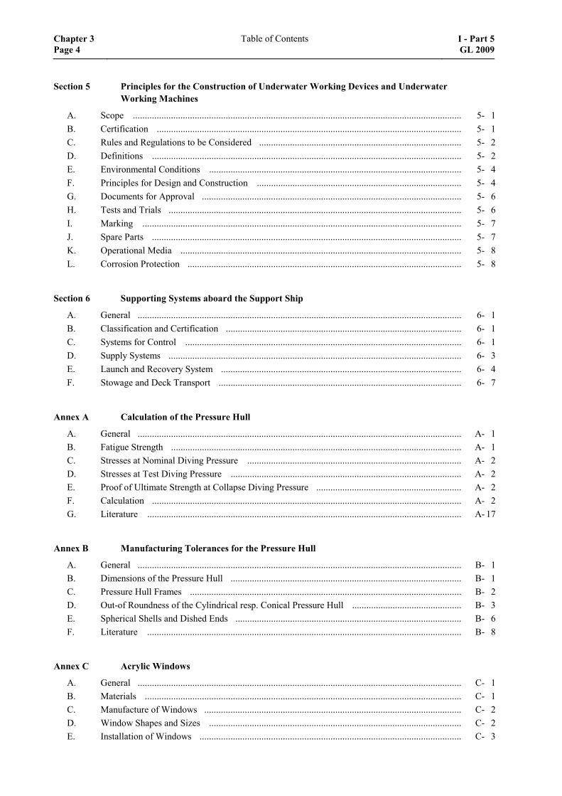
Section 5 Principles for the Construction of Underwater Working Devices and Underwater Working Machines
A. Scope .......................................................................................................................................... 5- 1 B. Certification ................................................................................................................................ 5- 1 C. Rules and Regulations to be Considered ..................................................................................... 5- 2 D. Definitions .................................................................................................................................. 5- 2 E. Environmental Conditions .......................................................................................................... 5- 4 F. Principles for Design and Construction ...................................................................................... 5- 4 G. Documents for Approval ............................................................................................................. 5- 6 H. Tests and Trials ........................................................................................................................... 5- 6 I. Marking ...................................................................................................................................... 5- 7 J. Spare Parts .................................................................................................................................. 5- 7 K. Operational Media ...................................................................................................................... 5- 8 L. Corrosion Protection ................................................................................................................... 5- 8
Section 6 Supporting Systems aboard the Support Ship
A. General ........................................................................................................................................ 6- 1 B. Classification and Certification ................................................................................................... 6- 1 C. Systems for Control .................................................................................................................... 6- 1 D. Supply Systems ........................................................................................................................... 6- 3 E. Launch and Recovery System ..................................................................................................... 6- 4 F. Stowage and Deck Transport ...................................................................................................... 6- 7
Annex A Calculation of the Pressure Hull
A. General ........................................................................................................................................ A- 1 B. Fatigue Strength .......................................................................................................................... A- 1 C. Stresses at Nominal Diving Pressure .......................................................................................... A- 2 D. Stresses at Test Diving Pressure ................................................................................................. A- 2 E. Proof of Ultimate Strength at Collapse Diving Pressure ............................................................. A- 2 F. Calculation .................................................................................................................................. A- 2 G. Literature .................................................................................................................................... A- 17
Annex B Manufacturing Tolerances for the Pressure Hull
A. General ........................................................................................................................................ B- 1 B. Dimensions of the Pressure Hull ................................................................................................. B- 1 C. Pressure Hull Frames .................................................................................................................. B- 2 D. Out-of Roundness of the Cylindrical resp. Conical Pressure Hull .............................................. B- 3 E. Spherical Shells and Dished Ends ............................................................................................... B- 6 F. Literature .................................................................................................................................... B- 8
Annex C Acrylic Windows
A. General ........................................................................................................................................ C- 1 B. Materials ..................................................................................................................................... C- 1 C. Manufacture of Windows ............................................................................................................ C- 2 D. Window Shapes and Sizes .......................................................................................................... C- 2 E. Installation of Windows .............................................................................................................. C- 3
Chapter 3 Page 4
Table of Contents I - Part 5GL 2009
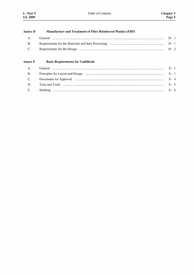
Annex D Manufacture and Treatment of Fibre Reinforced Plastics (FRP)
A. General ....................................................................................................................................... D- 1
B. Requirements for the Materials and their Processing ................................................................. D- 1
C. Requirements for the Design ...................................................................................................... D- 2
Annex E Basic Requirements for Umbilicals
A. General ....................................................................................................................................... E- 1
B. Principles for Layout and Design ............................................................................................... E- 1
C. Documents for Approval ............................................................................................................ E- 4
D. Tests and Trials .......................................................................................................................... E- 5
E. Marking ...................................................................................................................................... E- 6
I - Part 5 GL 2009
Table of Contents Chapter 3Page 5

Index
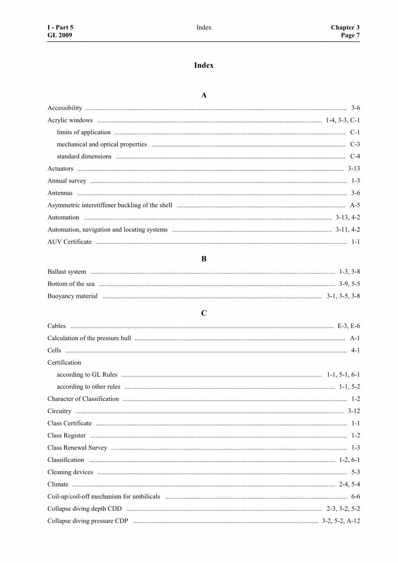
A Accessibility ........................................................................................................................................................... 3-6
Acrylic windows ..................................................................................................................................... 1-4, 3-3, C-1
limits of application ......................................................................................................................................... C-1
mechanical and optical properties ................................................................................................................... C-3
standard dimensions ........................................................................................................................................ C-4
Actuators .............................................................................................................................................................. 3-13
Annual survey ........................................................................................................................................................ 1-3
Antennas ................................................................................................................................................................ 3-6
Asymmetric interstiffener buckling of the shell .................................................................................................... A-5
Automation ................................................................................................................................................... 3-13, 4-2
Automation, navigation and locating systems ............................................................................................... 3-11, 4-2
AUV Certificate ..................................................................................................................................................... 1-1
B Ballast system ................................................................................................................................................. 1-3, 3-8
Bottom of the sea ............................................................................................................................................ 3-9, 5-5
Buoyancy material .................................................................................................................................. 3-1, 3-5, 3-8
C Cables ............................................................................................................................................................ E-3, E-6
Calculation of the pressure hull ............................................................................................................................. A-1
Cells ....................................................................................................................................................................... 4-1
Certification
according to GL Rules ....................................................................................................................... 1-1, 5-1, 6-1
according to other rules ............................................................................................................................. 1-1, 5-2
Character of Classification ..................................................................................................................................... 1-2
Circuitry ............................................................................................................................................................... 3-12
Class Certificate ..................................................................................................................................................... 1-1
Class Register ........................................................................................................................................................ 1-2
Class Renewal Survey ............................................................................................................................................ 1-3
Classification .................................................................................................................................................. 1-2, 6-1
Cleaning devices .................................................................................................................................................... 5-3
Climate ............................................................................................................................................................ 2-4, 5-4
Coil-up/coil-off mechanism for umbilicals ............................................................................................................ 6-6
Collapse diving depth CDD .................................................................................................................... 2-3, 3-2, 5-2
Collapse diving pressure CDP .............................................................................................................. 3-2, 5-2, A-12
I - Part 5 GL 2009
Index Chapter 3Page 7
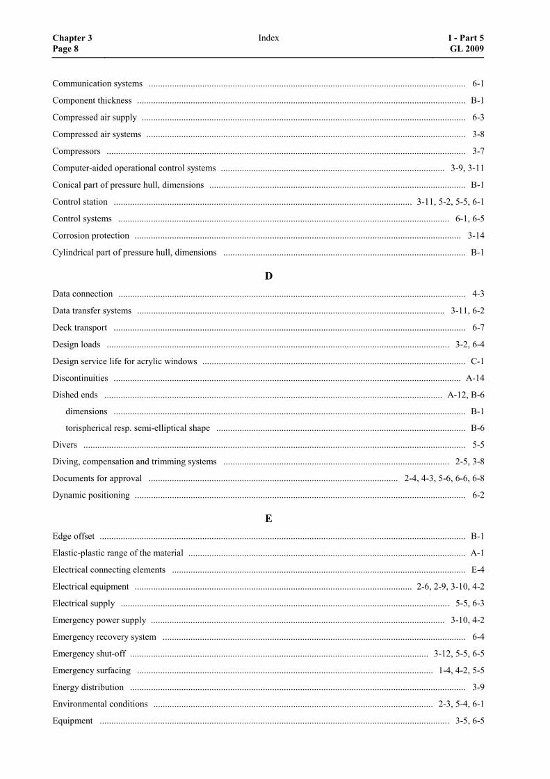
Communication systems ........................................................................................................................................ 6-1
Component thickness ............................................................................................................................................. B-1
Compressed air supply ........................................................................................................................................... 6-3
Compressed air systems ......................................................................................................................................... 3-8
Compressors .......................................................................................................................................................... 3-7
Computer-aided operational control systems ................................................................................................ 3-9, 3-11
Conical part of pressure hull, dimensions .............................................................................................................. B-1
Control station ................................................................................................................................ 3-11, 5-2, 5-5, 6-1
Control systems .............................................................................................................................................. 6-1, 6-5
Corrosion protection ............................................................................................................................................ 3-14
Cylindrical part of pressure hull, dimensions ........................................................................................................ B-1
D Data connection ..................................................................................................................................................... 4-3
Data transfer systems .................................................................................................................................... 3-11, 6-2
Deck transport ....................................................................................................................................................... 6-7
Design loads ................................................................................................................................................... 3-2, 6-4
Design service life for acrylic windows ................................................................................................................. C-1
Discontinuities ..................................................................................................................................................... A-14
Dished ends ................................................................................................................................................. A-12, B-6
dimensions ....................................................................................................................................................... B-1
torispherical resp. semi-elliptical shape ........................................................................................................... B-6
Divers .................................................................................................................................................................... 5-5
Diving, compensation and trimming systems ................................................................................................. 2-5, 3-8
Documents for approval ........................................................................................................... 2-4, 4-3, 5-6, 6-6, 6-8
Dynamic positioning .............................................................................................................................................. 6-2
E Edge offset ............................................................................................................................................................. B-1
Elastic-plastic range of the material ....................................................................................................................... A-1
Electrical connecting elements .............................................................................................................................. E-4
Electrical equipment ....................................................................................................................... 2-6, 2-9, 3-10, 4-2
Electrical supply ............................................................................................................................................. 5-5, 6-3
Emergency power supply .............................................................................................................................. 3-10, 4-2
Emergency recovery system .................................................................................................................................. 6-4
Emergency shut-off ................................................................................................................................ 3-12, 5-5, 6-5
Emergency surfacing ............................................................................................................................... 1-4, 4-2, 5-5
Energy distribution ................................................................................................................................................ 3-9
Environmental conditions ........................................................................................................................ 2-3, 5-4, 6-1
Equipment ...................................................................................................................................................... 3-5, 6-5
Chapter 3 Page 8
Index I - Part 5GL 2009
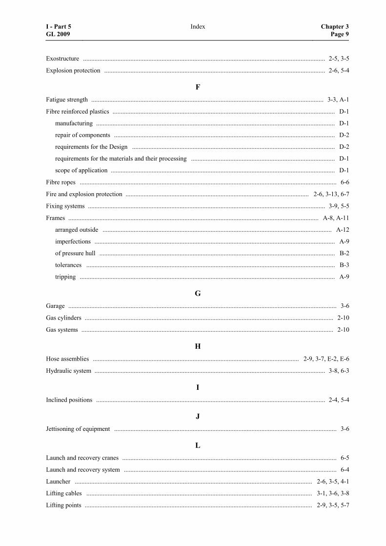
Exostructure .................................................................................................................................................... 2-5, 3-5
Explosion protection ....................................................................................................................................... 2-6, 5-4
F Fatigue strength .............................................................................................................................................. 3-3, A-1
Fibre reinforced plastics ........................................................................................................................................ D-1
manufacturing .................................................................................................................................................. D-1
repair of components ....................................................................................................................................... D-2
requirements for the Design ............................................................................................................................ D-2
requirements for the materials and their processing ........................................................................................ D-1
scope of application ......................................................................................................................................... D-1
Fibre ropes ............................................................................................................................................................. 6-6
Fire and explosion protection ................................................................................................................ 2-6, 3-13, 6-7
Fixing systems ................................................................................................................................................. 3-9, 5-5
Frames ......................................................................................................................................................... A-8, A-11
arranged outside ............................................................................................................................................ A-12
imperfections ................................................................................................................................................... A-9
of pressure hull ................................................................................................................................................ B-2
tolerances ........................................................................................................................................................ B-3
tripping ............................................................................................................................................................ A-9
G Garage .................................................................................................................................................................... 3-6
Gas cylinders ........................................................................................................................................................ 2-10
Gas systems .......................................................................................................................................................... 2-10
H Hose assemblies .............................................................................................................................. 2-9, 3-7, E-2, E-6
Hydraulic system ............................................................................................................................................. 3-8, 6-3
I Inclined positions ............................................................................................................................................ 2-4, 5-4
J Jettisoning of equipment ........................................................................................................................................ 3-6
L Launch and recovery cranes ................................................................................................................................... 6-5
Launch and recovery system .................................................................................................................................. 6-4
Launcher ................................................................................................................................................. 2-6, 3-5, 4-1
Lifting cables .......................................................................................................................................... 3-1, 3-6, 3-8
Lifting points ........................................................................................................................................... 2-9, 3-5, 5-7
I - Part 5 GL 2009
Index Chapter 3Page 9
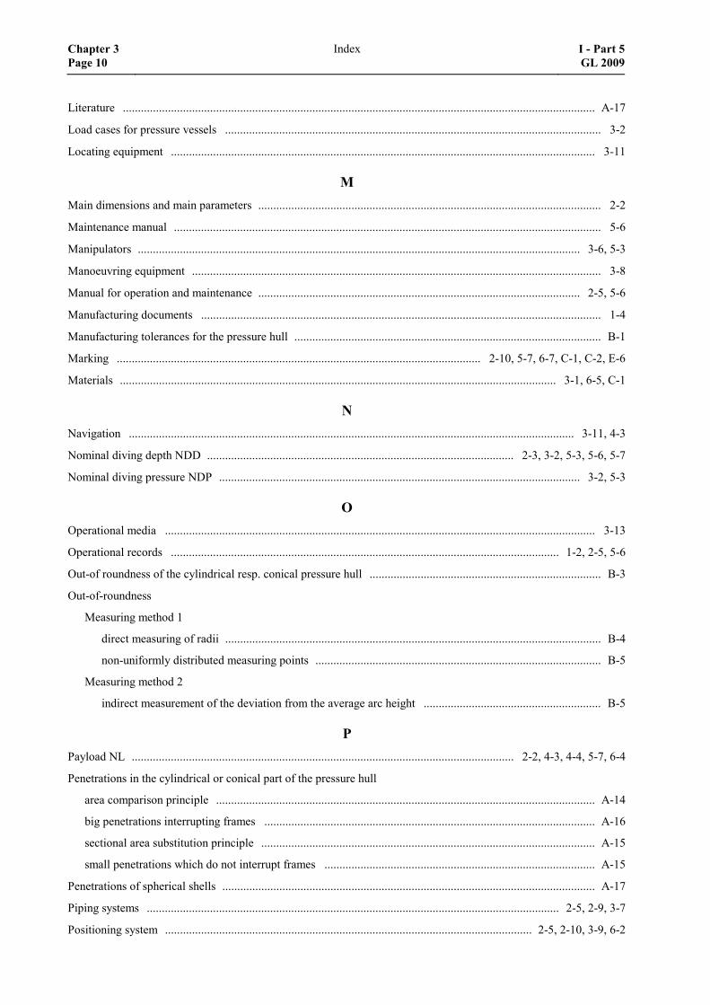
Literature ............................................................................................................................................................. A-17
Load cases for pressure vessels ............................................................................................................................. 3-2
Locating equipment ............................................................................................................................................. 3-11
M Main dimensions and main parameters .................................................................................................................. 2-2
Maintenance manual .............................................................................................................................................. 5-6
Manipulators ................................................................................................................................................... 3-6, 5-3
Manoeuvring equipment ........................................................................................................................................ 3-8
Manual for operation and maintenance ........................................................................................................... 2-5, 5-6
Manufacturing documents ..................................................................................................................................... 1-4
Manufacturing tolerances for the pressure hull ...................................................................................................... B-1
Marking ......................................................................................................................... 2-10, 5-7, 6-7, C-1, C-2, E-6
Materials ................................................................................................................................................. 3-1, 6-5, C-1
N Navigation .................................................................................................................................................... 3-11, 4-3
Nominal diving depth NDD ...................................................................................................... 2-3, 3-2, 5-3, 5-6, 5-7
Nominal diving pressure NDP ........................................................................................................................ 3-2, 5-3
O Operational media ............................................................................................................................................... 3-13
Operational records ................................................................................................................................. 1-2, 2-5, 5-6
Out-of roundness of the cylindrical resp. conical pressure hull ............................................................................. B-3
Out-of-roundness
Measuring method 1
direct measuring of radii ............................................................................................................................. B-4
non-uniformly distributed measuring points ............................................................................................... B-5
Measuring method 2
indirect measurement of the deviation from the average arc height ........................................................... B-5
P Payload NL ............................................................................................................................... 2-2, 4-3, 4-4, 5-7, 6-4
Penetrations in the cylindrical or conical part of the pressure hull
area comparison principle .............................................................................................................................. A-14
big penetrations interrupting frames .............................................................................................................. A-16
sectional area substitution principle ............................................................................................................... A-15
small penetrations which do not interrupt frames .......................................................................................... A-15
Penetrations of spherical shells ............................................................................................................................ A-17
Piping systems ......................................................................................................................................... 2-5, 2-9, 3-7
Positioning system .......................................................................................................................... 2-5, 2-10, 3-9, 6-2
Chapter 3 Page 10
Index I - Part 5GL 2009
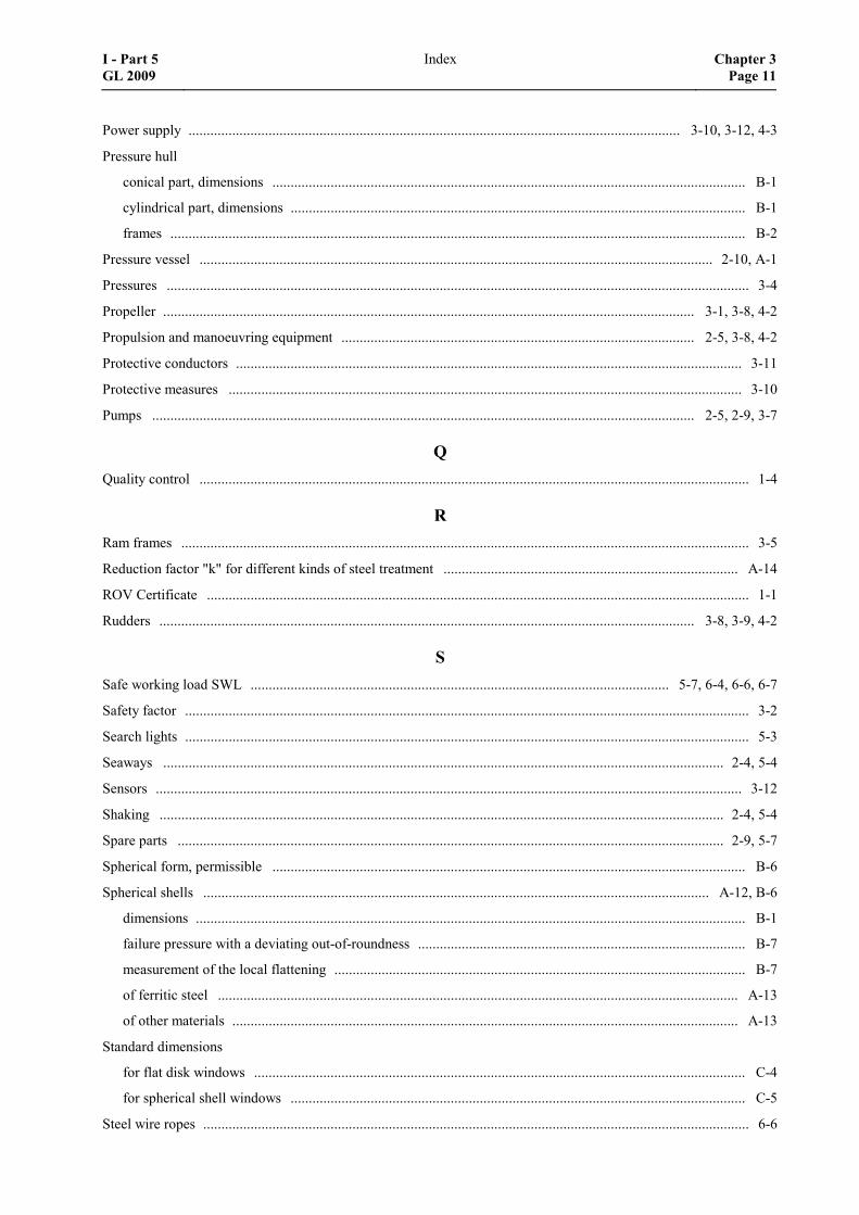
Power supply ....................................................................................................................................... 3-10, 3-12, 4-3
Pressure hull
conical part, dimensions .................................................................................................................................. B-1
cylindrical part, dimensions ............................................................................................................................. B-1
frames .............................................................................................................................................................. B-2
Pressure vessel ............................................................................................................................................. 2-10, A-1
Pressures ................................................................................................................................................................ 3-4
Propeller .................................................................................................................................................. 3-1, 3-8, 4-2
Propulsion and manoeuvring equipment ................................................................................................. 2-5, 3-8, 4-2
Protective conductors ........................................................................................................................................... 3-11
Protective measures ............................................................................................................................................. 3-10
Pumps ..................................................................................................................................................... 2-5, 2-9, 3-7
Q Quality control ....................................................................................................................................................... 1-4
R Ram frames ............................................................................................................................................................ 3-5
Reduction factor "k" for different kinds of steel treatment ................................................................................. A-14
ROV Certificate ..................................................................................................................................................... 1-1
Rudders ................................................................................................................................................... 3-8, 3-9, 4-2
S Safe working load SWL ................................................................................................................... 5-7, 6-4, 6-6, 6-7
Safety factor ........................................................................................................................................................... 3-2
Search lights ........................................................................................................................................................... 5-3
Seaways .......................................................................................................................................................... 2-4, 5-4
Sensors ................................................................................................................................................................. 3-12
Shaking ........................................................................................................................................................... 2-4, 5-4
Spare parts ...................................................................................................................................................... 2-9, 5-7
Spherical form, permissible .................................................................................................................................. B-6
Spherical shells ........................................................................................................................................... A-12, B-6
dimensions ....................................................................................................................................................... B-1
failure pressure with a deviating out-of-roundness .......................................................................................... B-7
measurement of the local flattening ................................................................................................................. B-7
of ferritic steel ............................................................................................................................................... A-13
of other materials ........................................................................................................................................... A-13
Standard dimensions
for flat disk windows ....................................................................................................................................... C-4
for spherical shell windows ............................................................................................................................. C-5
Steel wire ropes ...................................................................................................................................................... 6-6
I - Part 5 GL 2009
Index Chapter 3Page 11
Stowage ................................................................................................................................................................. 6-7
Stresses
at nominal diving pressure NDP ...................................................................................................................... A-2
at test diving pressure TDP .............................................................................................................................. A-2
for a conical pressure hull ................................................................................................................................ A-5
in a uniformly stiffened cylinder ...................................................................................................................... A-2
Stress-strain behaviour .......................................................................................................................................... A-7
Supply systems ...................................................................................................................................................... 6-3
Supporting structure ......................................................................................................................... 2-5, 2-9, 3-5, 4-1
Supporting systems aboard the support ship ............................................................................................ 1-2, 5-1, 6-1
Surveys
annual ............................................................................................................................................................... 1-3
Class renewal ................................................................................................................................................... 1-4
intermediate ..................................................................................................................................................... 1-3
maintenance of Class ....................................................................................................................................... 1-3
Swell compensators ............................................................................................................................................... 6-5
Symmetric interstiffener buckling of the shell ....................................................................................................... A-6
T Test diving depth TDD ............................................................................................................................ 2-3, 3-2, 5-3
Test diving pressure TDP ............................................................................................................................... 3-2, 5-3
Tether Management System (TMS) ................................................................................................................ 2-2, 6-6
Tide and currents ............................................................................................................................................ 2-4, 5-4
Tools ...................................................................................................................................................................... 5-5
Total system ............................................................................................................................................. 2-4, 2-7, 5-6
Towing point ......................................................................................................................................................... 3-5
Trial program .................................................................................................................................................. 2-5, 5-6
Trimming systems ........................................................................................................................................... 2-5, 3-8
U Ultimate strength ................................................................................................................................................... A-2
Umbilical winch .................................................................................................................................................... 6-6
Umbilicals ................................................................................................................................ 2-5, 2-9, 3-5, 3-6, 3-7
coil-up/coil-off mechanism .............................................................................................................................. E-4
documents for approval .................................................................................................................................... E-4
energy supply lines ........................................................................................................................................... E-3
jettisoning ........................................................................................................................................................ E-4
marking ............................................................................................................................................................ E-6
principles for layout and design ....................................................................................................................... E-1
tests .................................................................................................................................................................. E-5
Chapter 3 Page 12
Index I - Part 5GL 2009
Unmanned submersibles ........................................................................................................................................ 1-1
autonomous ............................................................................................................................................... 1-1, 4-2
remotely operated ...................................................................................................................................... 1-1, 3-1
V Vessels and apparatus under pressure ..................................................................................................... 1-4, 2-5, 3-3
Vibrations ....................................................................................................................................................... 2-4, 5-4
Video cameras ........................................................................................................................................................ 5-3
W Web frames ......................................................................................................................................... A-7, A-8, A-12
Weld sinkage ......................................................................................................................................................... B-1
Welding seams, evaluation .................................................................................................................................... B-2
Window
installation ....................................................................................................................................................... C-3
manufacturing .................................................................................................................................................. C-2
shapes .............................................................................................................................................................. C-2
Working devices ..................................................................................................................................... 3-5, 3-8, 5-3
Working functions ................................................................................................................................................. 5-5
Working machines ................................................................................................................................................. 5-5
Workmanship ......................................................................................................................................................... 1-4
I - Part 5 GL 2009
Index Chapter 3Page 13
Section 1
Certification and Classification of Unmanned Submersibles
A. Scope
1. These Rules are valid for the construction of unmanned submersibles (UUV) which shall be certi-fied or classified by Germanischer Lloyd (GL), in-cluding their operating and monitoring systems.
The requirements for the necessary supply systems and the systems for launch and recovery of submersi-bles on the support ship are summarized in Section 6.
Unmanned submersibles may be Remotely Operated Vehicles (ROV) or Autonomous Underwater Vehicles (AUV).
2. Remotely operated submersibles (ROV)
For the purpose of these Rules unmanned submersi-bles, which are during the mission physically con-nected with an umbilical to the relevant support ship and which are controlled from there, are regarded as remotely operated submersibles. As an exception also wireless remote control is possible.
3. Autonomous submersibles (AUV)
For the purpose of these Rules unmanned submersi-bles, which are during the mission not physically connected with the relevant support ship (e.g. with an umbilical), are regarded as autonomous submersibles (AUV). These vehicles may perform pre-defined mis-sions with the assistance of EDP-programming and active and/or passive sensors respectively single mis-sions under remote control.
4. For further definitions, see Section 2, C.
B. Certification
1. General
1.1 The application for Certification of a sub-mersible is to be made in writing to GL by the manu-facturer or operator.
1.2 Documents for the submersible are generally to be submitted to GL in triplicate respectively in case of electronic transmission as single issue for approval. The scope of the documents to be submitted depends on the type and equipment of the submersible and follows from Section 2, E.
1.3 Surveys which have to be performed by GL are to be notified to GL in due time.
2. Certification according to GL Rules
2.1 Opportunity for Certification
Unmanned submersibles, which are constructed and tested according to the rules and under survey of GL may receive a ROV respectively an AUV Certificate from GL.
2.2 Scope of Certification
The Certification comprises the complete submersible including its machinery, shipbuilding and electric installations.
An overview which additional system elements are to be certified shows Table 1.1.
2.3 ROV/AUV Certificate
2.3.1 After completion and successful testing of the submersible a ROV Certificate will be issued for re-motely operated vehicles respectively an AUV Cer-tificate will be issued for autonomous vehicles by GL.
2.3.2 The Certificate certifies the technical condi-tion of the submersible at the time of the tests and approvals by GL. In addition it will be confirmed that no safety reservations are opposing the operation of the submersible.
2.3.3 The validity of the ROV respectively AUV Certificate is 5 years at maximum and can be pro-longed after renewed tests. For maintaining the Cer-tificate the submersible is in general to be subjected to an Annual Survey. The scope has to be agreed with GL in each single case.
The ROV respectively AUV Certificate looses its validity if substantial changes have been performed at the submersible respectively if the submersible has been severely damaged and the change or the repair has not been agreed and approved by GL.
3. Certification according to other rules
3.1 For unmanned submersibles, which are not built according to the Rules of GL, the applied rules have to be defined in a binding way in the application for Certification.
3.2 After successful examination a Certificate may be issued by GL.
I - Part 5 GL 2009
Section 1 Certification and Classification of Unmanned Submersibles Chapter 3Page 1–1
B
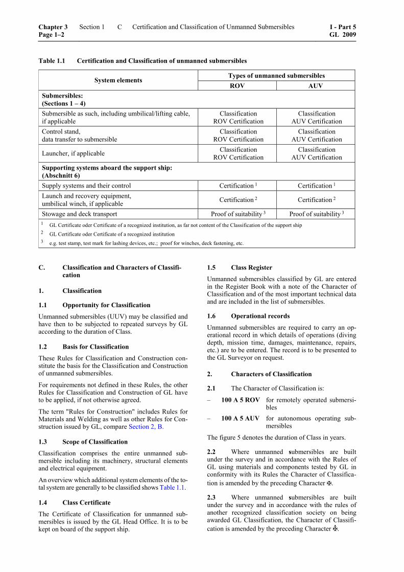
Table 1.1 Certification and Classification of unmanned submersibles
Types of unmanned submersibles System elements
ROV AUV Submersibles: (Sections 1 – 4) Submersible as such, including umbilical/lifting cable, if applicable
Classification ROV Certification
Classification AUV Certification
Control stand, data transfer to submersible
Classification ROV Certification
Classification AUV Certification
Launcher, if applicable Classification ROV Certification
Classification AUV Certification
Supporting systems aboard the support ship: (Abschnitt 6) Supply systems and their control Certification 1 Certification 1 Launch and recovery equipment, umbilical winch, if applicable Certification 2 Certification 2
Stowage and deck transport Proof of suitability 3 Proof of suitability 3 1 GL Certificate oder Certificate of a recognized institution, as far not content of the Classification of the support ship 2 GL Certificate oder Certificate of a recognized institution 3 e.g. test stamp, test mark for lashing devices, etc.; proof for winches, deck fastening, etc.
C. Classification and Characters of Classifi-cation
1. Classification
1.1 Opportunity for Classification
Unmanned submersibles (UUV) may be classified and have then to be subjected to repeated surveys by GL according to the duration of Class.
1.2 Basis for Classification
These Rules for Classification and Construction con-stitute the basis for the Classification and Construction of unmanned submersibles.
For requirements not defined in these Rules, the other Rules for Classification and Construction of GL have to be applied, if not otherwise agreed.
The term "Rules for Construction" includes Rules for Materials and Welding as well as other Rules for Con-struction issued by GL, compare Section 2, B.
1.3 Scope of Classification
Classification comprises the entire unmanned sub-mersible including its machinery, structural elements and electrical equipment.
An overview which additional system elements of the to-tal system are generally to be classified shows Table 1.1.
1.4 Class Certificate
The Certificate of Classification for unmanned sub-mersibles is issued by the GL Head Office. It is to be kept on board of the support ship.
1.5 Class Register
Unmanned submersibles classified by GL are entered in the Register Book with a note of the Character of Classification and of the most important technical data and are included in the list of submersibles.
1.6 Operational records
Unmanned submersibles are required to carry an op-erational record in which details of operations (diving depth, mission time, damages, maintenance, repairs, etc.) are to be entered. The record is to be presented to the GL Surveyor on request.
2. Characters of Classification
2.1 The Character of Classification is:
– 100 A 5 ROV for remotely operated submersi-bles
– 100 A 5 AUV for autonomous operating sub-mersibles
The figure 5 denotes the duration of Class in years.
2.2 Where unmanned submersibles are built under the survey and in accordance with the Rules of GL using materials and components tested by GL in conformity with its Rules the Character of Classifica-tion is amended by the preceding Character .
2.3 Where unmanned submersibles are built under the survey and in accordance with the rules of another recognized classification society on being awarded GL Classification, the Character of Classifi-cation is amended by the preceding Character .
Chapter 3 Page 1–2
Section 1 Certification and Classification of Unmanned Submersibles I - Part 5GL 2009
C
2.4 For submersibles and their equipment which are non-standard design, GL reserve the right to im-pose additional tests, to order a special survey sched-ule and to make special entries in the Certificate of the submersible and the Register Book.
3. Further class relevant requirements
Further requirements for Classification and mainte-nance of Class are contained in the GL Rules for Manned Submersibles (I-5-2), Section 1 and Clas-sification and Surveys (I-0) and are to be applied as far as possible analogously for unmanned submersibles.
4. Type approval for series vehicles
Unmanned submersibles which are manufactured in series may be subjected to a type test and certified or classified in a relevant way.
Kind and scope of the type tests as well as of the addi-tional construction supervision of the series are to be agreed with GL in each single case.
D. Surveys for Maintenance of Class
1. General
1.1 Surveys to be performed in the course of the constructional tests and acceptance tests on the un-manned submersible are performed by GL in accord-ance with these Rules in agreement with the manufac-turer or operator. For this scope see Section 2, F.
1.2 Surveys required under official regulations, international conventions or other arrangements are performed by GL on application or commission as required by the relevant provisions.
1.3 If the submersible has suffered substantial damage which impairs or nullifies the validity of the Certificate, GL will on application carry out damage and repair surveys and confirm the Certificate after the necessary repair measures have been performed.
1.4 Extraordinary surveys have to be carried out if modification is made in respect of design, mode of operation or equipment.
1.5 If it is an excessive effort to prepare units and components for survey on board, the surveys may also, on application, be performed at the manufac-turer's works or another authorized workshop.
2. Class surveys
The surveys are to be performed according to the following criteria. If the operational systems of a sub-mersible should be different from the standard case, the scope of the surveys may be adjusted accordingly in agreement with GL.
2.1 Annual Survey
The Annual Survey of the unmanned submersible includes at least the following tests and checks:
2.1.1 Examination of the documents relating to the submersible and scrutiny of the operational records.
2.1.2 The exostructure including the load bearing structure, all fixtures, doors and covers, lifting points, claddings, fixed buoyancy aids, etc. are to be in-spected for visible damage, cracks, deformation, cor-rosion attacks and fouling, etc.
2.1.3 Check of the measures for corrosion protec-tion (e.g. anodes).
2.1.4 All vessels and apparatus under external or internal overpressure, penetrations, viewports, valves, fittings and relevant safety equipment are to be sub-jected to external inspection.
2.1.5 The entire machinery installation including electrical equipment and eventual redundancy systems are to be subjected to external inspection.
2.1.6 Check that insulation measurements have been performed on the electrical equipment.
2.1.7 Review of safety systems and of the set points of the safety devices.
2.1.8 Function test of all alarm systems.
2.1.9 Switching from the main to the emergency electricity supply of the submersible, if existing, is to be tested.
2.1.10 The accuracy of all essential instrument read-ings is to be checked (e.g. depth gauge, etc.).
2.1.11 All emergency systems (e.g. release mecha-nism, emergency signals) are to undergo a functional test - as far as applicable.
2.1.12 Check of the ballast system.
2.1.13 Hose assemblies are to be checked for visible damages.
2.1.14 The umbilical and lifting cable - if applicable - is to be checked for visible damages, cracks, defor-mations and corrosion.
2.1.15 The function of the equipment for data trans-fer is to be checked.
2.1.16 The functional efficiency of the total system is to be checked by means of a trial dive.
2.2 Intermediate Survey
The Intermediate Survey falls due nominally 2,5 years after commissioning and each Class Renewal and may be carried out on the occasion of the second or third Annual Survey.
I - Part 5 GL 2009
Section 1 Certification and Classification of Unmanned Submersibles Chapter 3Page 1–3
D
An Intermediate Survey is an Annual Survey accord-ing to 2.1 extended by the following scope:
2.2.1 Performance of a tightness test on vessels under external pressure by application of a vacuum of at least 0,2 bar below atmospheric pressure or other suitable test procedures, as far as applicable.
2.2.2 Tightness test of ballast water system, if existing.
2.2.3 Tightness test of hose assemblies.
2.2.4 External visual check and eventual functional test, if applicable, of the extension elements/working devices belonging to the submersible.
2.3 Class Renewal Survey
Every five years a Class Renewal Survey will be car-ried out. In addition to the surveys defined in 2.2 the following tests and examinations are to be carried out for Class Renewal Surveys:
2.3.1 Check of the shell cladding and buoyancy aids (pressure resistant foam) from all sides. If neces-sary the cladding has to be removed.
2.3.2 Check of the areas of the load bearing struc-ture which are not easily accessible with the aid of non-destructive test procedures.
2.3.3 For vessels and apparatus under pressure, which cannot be satisfactorily inspected internally or their satis-factory condition cannot be fully verified by internal inspection, another non-destructive test method is to be used or a hydraulic pressure test is to be performed additionally. As far as necessary buoyancy materials, cladding or heat insulation layers are to be removed.
2.3.4 Acrylic windows are to be dismantled, if necessary, and are to be checked for cracks. The win-dow seatings are to be checked for corrosion and dam-ages.
2.3.5 Check of systems for emergency surfacing and the resulting floating condition at the water surface.
2.3.6 Check that accessories, especially hose as-semblies and compensators have been changed ac-cording to the maintenance plan.
E. Workmanship
1. General
1.1 Requirements to be complied with by the manufacturer and supplier
1.1.1 Each workshop of a manufacturer/supplier has to be provided with suitable equipment and facili-ties to enable proper handling of the respective mate-
rials, manufacturing processes, structural components, etc. GL reserve the right to inspect the workshops accordingly and ask for related requirements or to restrict the scope of manufacture to the potential available at the plant.
For safety relevant components and elements it is to be defined by GL if the manufacturer/supplier needs an approval by GL. Components and elements are regarded as safety relevant, if a direct danger for per-sons or the submersible may be created by them.
1.1.2 The manufacturing plants are to have at their disposal sufficiently qualified personnel. The supervi-sory and control personnel is to be named to GL, the areas of responsibility are to be defined. GL reserve the right to require proof of qualification.
1.2 Quality control
1.2.1 The manufacturer/supplier has to apply a quality management system, like e.g. ISO 9001 or equivalent.
1.2.2 As far as required and expedient, all compo-nents both during manufacture and on completion are to be checked for completeness, correct dimensions and faultless workmanship according to the standard of good engineering practice.
1.2.3 Upon inspection and eventual corrections by the manufacturing plant, the structural components are to be presented to the GL Surveyor for inspection, in suitable construction sections, normally in uncoated condition and enabling proper access for inspection.
1.2.4 The GL Surveyor may reject components that have not been adequately pre-checked and may de-mand their resubmission upon successful checks by the manufacturer and, if necessary, corrective actions.
2. Details in manufacturing documents
2.1 All significant details concerning quality and functional ability of the component concerned shall be entered in the manufacturing documents (workshop drawings, etc.). This includes besides scantlings - where relevant - such items as surface conditions (e.g. finishing of flame cut edges and weld seams), special methods of manufacture involved as well as inspection and acceptance requirements and where relevant per-missible tolerances.
As far as a standard (works standard, national standard, etc.) shall be used it has to be harmonized with GL.
2.2 If, due to missing or insufficient details in the manufacturing documents, the quality or functional ability of the component cannot be guaranteed or is doubtful, GL may require appropriate improvements. This is valid analogously for supplementary or addi-tional parts (e.g. reinforcements), even if these were not required at the time of plan approval or if - as a result of insufficient detailing - could not be required.
Chapter 3 Page 1–4
Section 1 Certification and Classification of Unmanned Submersibles I - Part 5GL 2009
E
Section 2
Principles for the Construction of Unmanned Submersibles
A. General Principles
1. Wherever expedient and feasible, submersi-bles are to be designed and constructed in such a way that failure of any single component cannot give rise to a dangerous situation.
2. Submersibles and their components are to be designed to meet the service conditions stated in the specification.
3. Submersibles are to be designed and built to ensure safe operation and facilitate proper mainte-nance and the necessary surveys.
4. Submersibles are to be designed and con-structed in such a way that sufficient possibilities for monitoring during dived travels are given. This can be achieved e.g. by video systems and acoustic instru-ments.
B. Rules and Regulations to be Considered
1. Rules of GL
1.1 The following Rules are valid as additional requirements for the Certification/Classification and construction of submersibles in addition to the GL Rules for Classification and Construction of these vehicles:
– Part 0 – Classification and Surveys
– Part 1 – Seagoing Ships, Chapter 1 - 4, if applicable
– II – Materials and Welding, Part 1 - 3
1.2 For supporting systems aboard the support ship see Section 6.
1.3 Designs differing from the Rules of Con-struction may be permitted provided that they have been recognized by GL as equivalent.
1.4 Submersibles or parts thereof whose devel-opment is based on new principles and which have not yet been sufficiently tested in practical operation re-quire special approval by GL.
1.5 In the cases mentioned in 1.3 and 1.4, GL is entitled to require the submission of additional docu-mentation and the performance of special tests.
1.6 GL reserve the right to impose demands addi-tional to those contained in the Rules in respect of all types of submersibles when such action is necessitated by new knowledge or practical experience, or to sanction deviations from the Rules in specially justified cases.
2. National regulations
National regulations existing alongside GL's Rules are unaffected.
3. International Conventions and Codes
Where reference is made to international Conventions and Codes examples are listed in the following:
3.1 MARPOL 73/78
International Convention for the Prevention of Pollu-tion from Ships, 1973 including the 1978 Protocol as amended.
3.2 SOLAS 74
International Convention for the Safety of Life at Sea, 1974, as amended.
3.3 COLREGS 1972
International Regulations of 1972 to prevent collisions at sea.
C. Definitions
1. General
Autonomous submersible (AUV)
Submersible which is not physically connected to the support ship during operation (e.g. by an umbilical) and which is able to perform pre-defined missions with the aid of EDP-programming and active and/or passive sensors. Further on they are recovered by a support ship, supplied, maintained and transferred to the location of the next mission.
Control stand
Desk or console at which all essential indicators, con-trols, regulating devices, monitoring devices for the remote operation of the submersible are arranged.
Diving pressure
The pressure, corresponding to the relevant diving depth, to which a submersible or diver is exposed during underwater operations.
I - Part 5 GL 2009
Section 2 Principles for the Construction of Unmanned Submersibles Chapter 3Page 2–1
C
Exostructure
External fairing, supporting structures and fixtures outside of pressure vessels which are normally not designed to withstand the diving pressure.
Fixing system
Device for short time fixing of a submersible e.g. on a structure.
Garage
Cage into which the submersible can be launched and recovered in a protected way. The garage will in gen-eral be part of a launcher.
Gas cylinders
Bottles for the storage and transport of gases under pressure.
Launcher
Device for launching and recovering of the submersi-ble from the support ship and from which the sub-mersible can start under water to the location of the mission. For remotely operated submersibles (ROV) the launcher is connected by lifting cable and rela-tively long supply lines with the support ship and contains normally the drum (e.g. TMS – Tether Man-agement System) for the umbilical from the launcher to the submersible.
Launching and recovering system
The plant and equipment necessary for launching and recovering a submersible.
Lifting cable
Cable for launching and recovering of submersibles and also for lifting and lowering of a remotely oper-ated submersible.
Payload NL of the submersible
Maximum additional load for devices, equipment, materials, which are not necessary for the direct opera-tion of the submersible, but are serving for work to be performed, investigation of the sea and scientific re-search.
Positioning system
System for keeping a pre-defined position (breadth, length, depth)
Pressure vessel
A container capable of withstanding an internal or external overpressure.
Remotely operated submersible (ROV)
Submersible which is during the mission physically connected to the related support ship by an umbilical and is controlled from there. As an exception also wireless remote control is possible.
Safe working load SWL of the launching and re-covery system
The safe working load SWL is the load which may be loaded directly to the launching and recovery system. The dead load of the load transmitting device which are not fixed to the launch and recovery system, but are used as connection between load and lifting appli-ance, are part of the safe working load SWL.
Supporting structure
Frame or rack in which the single components of the submersible are arranged together.
Supporting systems
Systems on the support ship, which are supporting especially remotely operated, but also autonomous submersibles with supplies necessary for the opera-tion, like e.g. electrical energy, hydraulic liquid, as well as control and monitoring data.
Support ship
A surface vessel for support and supply of remotely operated and autonomous submersibles. Within these Rules the support ship may also be a stationary supply station (e.g. on the coast or on a stationary offshore plant).
Total system
The submersible including its control, launching, recovery, storage, transport and supply systems.
Umbilical
Connection between support ship and remotely oper-ated submersible, which might contain control, moni-toring, data transfer and energy supply lines and, if applicable, also a lifting cable.
This supply line can also be used between a launcher and the submersible or between the submersible and a diver.
Working device (underwater)
Device, e.g. manipulator, sample container and tools, which are fixed to the submersible and which are designated to the performance of underwater tasks and the reception of e.g. samples.
Working machine (underwater)
Machines, e.g. grab, driver, drill and their combina-tion, which are normally used from a support ship to perform underwater tasks.
2. Main dimensions and main parameters
All dimensions are related to fix installed equipment in drawn-in/turned-in condition.
2.1 Co-ordinate system
In relation to the submersible a fixed, right-handed co-ordinate system x, y, z according to Fig. 2.1 is intro-
Chapter 3 Page 2–2
Section 2 Principles for the Construction of Unmanned Submersibles I - Part 5GL 2009
C
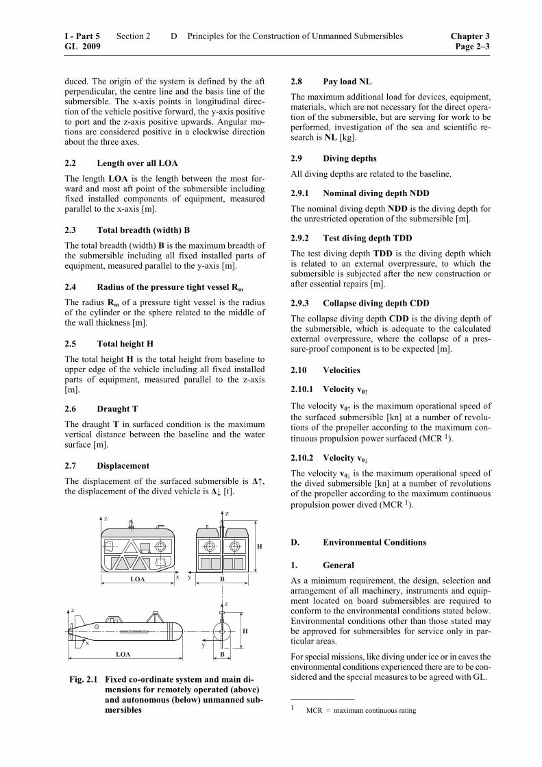
duced. The origin of the system is defined by the aft perpendicular, the centre line and the basis line of the submersible. The x-axis points in longitudinal direc-tion of the vehicle positive forward, the y-axis positive to port and the z-axis positive upwards. Angular mo-tions are considered positive in a clockwise direction about the three axes.
2.2 Length over all LOA
The length LOA is the length between the most for-ward and most aft point of the submersible including fixed installed components of equipment, measured parallel to the x-axis [m].
2.3 Total breadth (width) B
The total breadth (width) B is the maximum breadth of the submersible including all fixed installed parts of equipment, measured parallel to the y-axis [m].
2.4 Radius of the pressure tight vessel Rm
The radius Rm of a pressure tight vessel is the radius of the cylinder or the sphere related to the middle of the wall thickness [m].
2.5 Total height H
The total height H is the total height from baseline to upper edge of the vehicle including all fixed installed parts of equipment, measured parallel to the z-axis [m].
2.6 Draught T
The draught T in surfaced condition is the maximum vertical distance between the baseline and the water surface [m].
2.7 Displacement
The displacement of the surfaced submersible is Δ↑, the displacement of the dived vehicle is Δ↓ [t].
�
� �
�
��� �
�
�
�
�
�
�
�
���
Fig. 2.1 Fixed co-ordinate system and main di-mensions for remotely operated (above) and autonomous (below) unmanned sub-mersibles
2.8 Pay load NL
The maximum additional load for devices, equipment, materials, which are not necessary for the direct opera-tion of the submersible, but are serving for work to be performed, investigation of the sea and scientific re-search is NL [kg].
2.9 Diving depths
All diving depths are related to the baseline.
2.9.1 Nominal diving depth NDD
The nominal diving depth NDD is the diving depth for the unrestricted operation of the submersible [m].
2.9.2 Test diving depth TDD
The test diving depth TDD is the diving depth which is related to an external overpressure, to which the submersible is subjected after the new construction or after essential repairs [m].
2.9.3 Collapse diving depth CDD
The collapse diving depth CDD is the diving depth of the submersible, which is adequate to the calculated external overpressure, where the collapse of a pres-sure-proof component is to be expected [m].
2.10 Velocities
2.10.1 Velocity v0↑
The velocity v0↑ is the maximum operational speed of the surfaced submersible [kn] at a number of revolu-tions of the propeller according to the maximum con-tinuous propulsion power surfaced (MCR 1).
2.10.2 Velocity v0↓
The velocity v0↓ is the maximum operational speed of the dived submersible [kn] at a number of revolutions of the propeller according to the maximum continuous propulsion power dived (MCR 1).
D. Environmental Conditions
1. General
As a minimum requirement, the design, selection and arrangement of all machinery, instruments and equip-ment located on board submersibles are required to conform to the environmental conditions stated below. Environmental conditions other than those stated may be approved for submersibles for service only in par-ticular areas.
For special missions, like diving under ice or in caves the environmental conditions experienced there are to be con-sidered and the special measures to be agreed with GL.
–––––––––––––– 1 MCR = maximum continuous rating
I - Part 5 GL 2009
Section 2 Principles for the Construction of Unmanned Submersibles Chapter 3Page 2–3
D
2. Inclined positions
If not specified otherwise satisfactory functioning shall be ensured at (static and dynamic) inclinations of up to 22,5° in any direction measured in relation to the as-installed datum. Transient inclinations of up to 45° shall not adversely affect operation and shall not cause damage, particularly to machine mountings. For greater operational inclinations these have to be con-sidered adequately for design and testing.
3. Water
For the design of submersibles and components the temperature range of the water as well as the range of salt content and therefore of the density is to be de-fined. If not agreed otherwise, seawater with a tem-perature range from –2 °C to +32 °C, with a salt con-tent of 3,5 % and a density of 1028 kg/m3 may be used as a basis. A value of 0,101 bar/m is to be applied when converting diving depth to pressure.
4. Seaways
The seaways up to which the submersible shall be operated in surfaced condition are to be agreed with GL. If not agreed otherwise, submersibles are to be designed for sea states with a significant wave height of at least 2 m, allowance being made for accelera-tions of 2 g downwards and 1 g upwards in the vertical and 1 g each in the longitudinal and transverse direc-tions (g = 9,81 m/s2).
5. Tide and currents
For the design of the propulsion and manoeuvring arrangement the different influences of currents ac-cording to the operation area and their possible com-binations are to be considered.
As basis for the design the maximum as well as the minimum tide at the relevant operation area shall be included. In addition currents created by wind or geo-graphic specialities (e.g. narrow channels) are to be considered.
6. Climate
For transport, maintenance, inspection and trials out of water on board of support ships as well as for launch and recovery systems for the submersible salt impreg-nated air ranging in temperature from –10 °C to +55 °C at an relative atmospheric humidity of 100 % is to be considered.
In specially protected control rooms for remotely operated submersibles on board of support ships, a relative atmospheric humidity of 80 % at a reference temperature of 45 °C is to be considered.
7. Vibrations and shaking
Machinery shall not cause any vibration or shaking which imposes unacceptable stresses on other ma-chines, equipment or the hull of the submersible. The
amplitudes and accelerations defined in the GL Rules for Machinery Installations (I-1-2), Section 1, C. are to be complied with.
8. Explosion protection
Submersibles which are used in respectively from explosion endangered areas (e.g. of oil and gas deliv-ering platforms) are to be designed for the relevant explosion zones. This is also valid for control stands.
9. Further environmental conditions
For the design of the submersible also the environ-mental conditions occurring during an eventual air transport (e.g. underpressure/temperature) are to be considered.
E. Documents for Approval
1. General
1.1 Before the start of manufacture, plans of the total system and drawings of all components and sys-tems subject to compulsory inspection, wherever ap-plicable and to the extent specified below, are to be submitted to in triplicate respectively in case of elec-tronic transmission as single issue.
1.2 The documents shall contain all the data necessary to check the design and loading of the equipment. Wherever necessary, calculations relating to components and descriptions of the system are to be submitted.
1.3 Once the documents submitted have been approved by GL, they become binding for the execu-tion. Any subsequent modifications require GL's con-sent before they are implemented.
2. Total system
The following documents are to be submitted:
2.1 A description of the submersible with details of its mode of operation, the proposed application and the essential design data including e.g.:
– nominal diving depth
– maximum operating time and maximum func-tion time of identification signals
– maximum range of a mission (radius)
– diving procedure
– operating limits for launching and recovery (seaway)
– other operating limits in relation to environ-mental conditions (e.g. salt water / fresh water or geographical peculiarities due to currents)
Chapter 3 Page 2–4
Section 2 Principles for the Construction of Unmanned Submersibles I - Part 5GL 2009
E
– speed below and eventually above water as well as maximum towing speed
– type of propulsion and manoeuvring equipment
– type and extent of working devices and equip-ment
– weight of vehicle, payload and ballast, dis-placement (submerged)
2.2 General arrangement drawing and plans show-ing design details of the submersible, including speci-fications for materials, manufacture and testing.
2.3 Drawings (block diagrams) of the total sys-tem.
2.4 Failure Modes and Effects Analysis (FMEA), if necessary.
2.5 A comprehensive presentation of the meas-ures taken to prevent corrosion.
2.6 Stability documentation (according to aim of mission and design)
2.7 Manual for operation and maintenance
The manual for the operation shall include in detail the steps necessary for normal operation as well as for emergency operation in a clear and conceptual form and in the necessary sequence (e.g. as checklist). In addition the measures for the loading of the operating systems (e.g. batteries) are to be defined. In addition the planned lifetime as well as the permissible load and mission cycles of parts of the equipment (e.g. acrylic windows, batteries) is to be defined herein.
The maintenance manual shall include all procedures for preventive maintenance as well as for periodic inspections.
2.8 Operational records
All conditions relevant for operation (diving depth, mis-sion time, damages, etc.) are to be documented herein.
2.9 Trial program.
3. Supporting structure and exostructure
Drawings of the supporting and exostructure of the submersible are to be submitted with data concerning extensions like trimming weights, diving cells, pres-sure vessels, buoyancy elements, stabilizing fins, drives, umbilical connection, control box, search lights, ram protection, fairing, manipulators, fixing systems, instrument racks, etc.
4. Vessels and apparatus under pressure
Drawings of the vessels and apparatus under external and internal pressure are to be submitted with all es-sential particulars and details necessary for appraising the safety of the equipment and including the specifi-cations for materials, manufacture and testing.
5. Piping systems, umbilicals, and pumps
The following are to be submitted:
5.1 Schematic diagrams of all piping systems including details of:
– materials
– maximum allowable working pressure
– maximum allowable working temperature
– dimensions (diameter, wall thickness)
– media carried
– type of valves and connections used and their operational parameters
– type of hose assemblies
5.2 Description of pumps and their drives to-gether with all important design and operating data.
5.3 Description of the design of the umbilical and its single elements as well as the requirements for lifting cables according to Annex E, C.
5.4 Listing of the components filled with liquids with definition of the type of liquid (e.g. oil, water).
6. Diving, compensation and trimming sys-tems
6.1 Submission of arrangement of diving, regu-lating and trimming systems with mathematical proof of the static diving capability
6.2 For open and closed loop control are to be submitted:
– description of the systems for depth, positive and negative buoyancy and trim including the necessary diagrams and component drawings
– data concerning scope, type and design of buoy-ancy and ballast elements and their fixing on the supporting structure
7. Propulsion and manoeuvring equipment
Drawings and descriptions of the propulsion and ma-noeuvring equipment are to be submitted with data about:
– mode of operation and control of the systems
– power demand (type and quantity)
– method of power transmission to propulsion unit
– safety systems
8. Positioning system
– The type and control of the positioning system is to be explained.
I - Part 5 GL 2009
Section 2 Principles for the Construction of Unmanned Submersibles Chapter 3Page 2–5
E
9. Working devices
(compare also Section 5, G.)
9.1 For extension elements and working devices the effects on the total system are to be defined.
9.2 Plans and descriptions of the working devices provided are to be submitted with data concerning:
– task of the devices/mission parameter
– type of operation and energy supply
– control and monitoring
– safety arrangements
– location and fixing at the supporting structure
– applied materials
– type of release system, if applicable
9.3 Plans and descriptions of the fixing system are to be submitted with information for
– type and control of the fixing system
– size of holding power
– behaviour at energy failure
– type of release system
10. Electrical equipment
The following are to be submitted:
10.1 A general arrangement drawing of the elec-trical equipment containing at least the following information:
– voltage rating of the systems
– power resp. current ratings of electrical consumers
– switchgear and safety systems (e.g. overload protection) with indicating settings for overload and overload protection
– cable types and cross-sections
10.2 The energy balance of power supply.
10.3 Plans and descriptions of the electrical energy supply system.
10.4 Drawings of switchgear and distribution equipment with parts list.
10.5 Complete documentation for electric motor drives with details of control, measuring and monitor-ing systems.
10.6 Battery installation drawing with details of battery types.
10.7 Details of electrical penetrations through pressure vessel walls.
10.8 Calculation of short-circuit conditions of all electrical components and distribution systems (e.g. power switches, power protection switches and fuses with data about the current ratings and breaking ca-pacity).
10.9 For the operation in explosive endangered areas the required explosion classes are to be proven.
10.10 Description of the electrical design of the umbilical as well as the connection to the submersible.
11. Automation, navigation and locating sys-tems
The following are to be submitted:
11.1 Description of the complete layout of the instruments at the control stand of remotely operated submersibles.
11.2 Description of the control and operating ele-ments for the submersible and its equipment.
11.3 Description of the nautical and diving in-strumentation, including speed and position indicators.
11.4 A description of the safety and alarm sys-tems.
11.5 Arrangement drawings/block diagrams of monitoring systems including lists of measuring points.
11.6 Documentation for electronic components such as instrument amplifiers, computers and periph-eral units.
11.7 General diagrams and equipment lists for the data transmission systems and signalling equipment.
11.8 General diagram and description of the Video system.
11.9 Descriptions, general diagrams and equip-ment lists for the locating equipment.
12. Fire and explosion protection
The following are to be submitted:
Description of preventive fire and explosion protec-tion measures for the submersibles which shall be used in or from explosion endangered areas.
13. Launcher
The following are to be submitted:
13.1 Plans and descriptions of the launcher with data about operating conditions, task and equipment.
Chapter 3 Page 2–6
Section 2 Principles for the Construction of Unmanned Submersibles I - Part 5GL 2009
E
13.2 Plans and descriptions of the garage system, if applicable, and equipment of the garage.
13.3 Description of the connections between the support ship and the launcher as well as between the launcher and the submersible.
F. Failure Modes and Effects Analysis (FMEA)
1. General
1.1 The Failure Modes and Effects Analysis (FMEA) has the purpose to identify possible failures in the total system, in subsystems and in components of unmanned submersibles/vehicles and to describe the effects on the total system and its subsystems resp. components.
1.2 For unmanned submersibles an analysis con-cerning the function and availability of the submersi-ble after occurrence of a single failure has to be sub-mitted if requested by GL.
1.3 The FMEA shall be executed in an early stadium accompanying the design to be able to realize system modification at due time. A tabular form, e.g. according to IEC 60812 is to be used.
2. Description of the subsystems relevant for the analysis
2.1 The FMEA shall represent an independent document and be understandable without consulting further documentation. This means that all relevant subsystems are to be described concerning the struc-ture of their basic functions, the installed redundancies and especially the interfaces of the subsystems to each other.
2.2 The description shall provide the operating personnel with a good overview of the vehicle struc-ture and the functionalities of the relevant subsystems. For all subsystems typical failure modes and their effects on the overall function of the vehicle shall be indicated. Further on the corrective actions to manage these failures and their effects are to be provided.
2.3 For unmanned submersibles the following subsystems are relevant for maintaining the overall function:
– exo-supporting structure and equipment
– pressure hull penetrations and equipment
– systems for control of depth, trimming, positive and negative buoyancy
– vessels and apparatus under pressure
– piping systems, fittings, pumps and compressors, mainly for remotely operated vehicles (ROV)
– Umbilicals, for ROVs
– propulsion and manoeuvring equipment
– electrical installations
– emergency power supply
– control, automation, data transfer, navigation and locating equipment
– fire and explosion protection
– launch and recovery system/launcher
– coil–up/coil–off mechanism for umbilicals, for ROVs
– mating equipment
– systems for control aboard the support ship
– supply systems aboard the support ship
– stowage and deck transport
– rescue systems
The system descriptions are to be completed by block diagrams according to 3.
3. Block diagrams of the relevant subsystems
For each relevant subsystem a block diagram is to be established. This block diagram shall contain the es-sential information of the system required for the failure analysis, which is normally:
– definition of the subsystems
– all essential components of the subsystems
– interfaces between the components of the sub-systems
– interfaces to or from other subsystems (typical for hydraulic drives and controls, etc.)
– arrangements for control of the total system submersible
– supplies from outside the total system vehicle, if applicable
– further aspects depending on the actual design of the submersible
4. Analysis of the different relevant subsys-tems
Each relevant subsystem is to be analyzed with regard to the following essential aspects, in course of which further aspects may occur during the execution of the analysis, compare work sheet (Table 2.1):
– failure of subsystems
– malfunctions of subsystems
– failure of components in a subsystem
– malfunctions of components
I - Part 5 GL 2009
Section 2 Principles for the Construction of Unmanned Submersibles Chapter 3Page 2–7
F
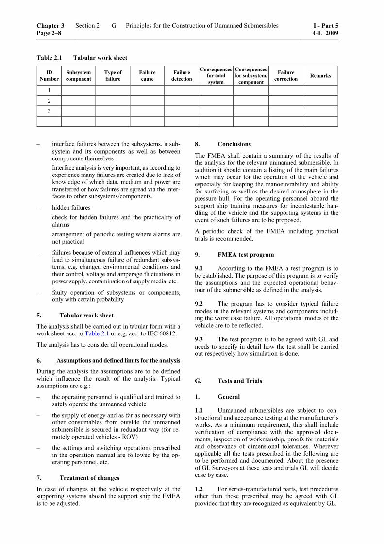
Table 2.1 Tabular work sheet
ID Number
Subsystem component
Type of failure
Failure cause
Failure detection
Consequences for total system
Consequences for subsystem/
component
Failure correction Remarks
1 2 3
– interface failures between the subsystems, a sub-system and its components as well as between components themselves
Interface analysis is very important, as according to experience many failures are created due to lack of knowledge of which data, medium and power are transferred or how failures are spread via the inter-faces to other subsystems/components.
– hidden failures check for hidden failures and the practicality of
alarms arrangement of periodic testing where alarms are
not practical
– failures because of external influences which may lead to simultaneous failure of redundant subsys-tems, e.g. changed environmental conditions and their control, voltage and amperage fluctuations in power supply, contamination of supply media, etc.
– faulty operation of subsystems or components, only with certain probability
5. Tabular work sheet
The analysis shall be carried out in tabular form with a work sheet acc. to Table 2.1 or e.g. acc. to IEC 60812.
The analysis has to consider all operational modes.
6. Assumptions and defined limits for the analysis
During the analysis the assumptions are to be defined which influence the result of the analysis. Typical assumptions are e.g.:
– the operating personnel is qualified and trained to safely operate the unmanned vehicle
– the supply of energy and as far as necessary with other consumables from outside the unmanned submersible is secured in redundant way (for re-motely operated vehicles - ROV)
– the settings and switching operations prescribed in the operation manual are followed by the op-erating personnel, etc.
7. Treatment of changes
In case of changes at the vehicle respectively at the supporting systems aboard the support ship the FMEA is to be adjusted.
8. Conclusions
The FMEA shall contain a summary of the results of the analysis for the relevant unmanned submersible. In addition it should contain a listing of the main failures which may occur for the operation of the vehicle and especially for keeping the manoeuvrability and ability for surfacing as well as the desired atmosphere in the pressure hull. For the operating personnel aboard the support ship training measures for incontestable han-dling of the vehicle and the supporting systems in the event of such failures are to be proposed.
A periodic check of the FMEA including practical trials is recommended.
9. FMEA test program
9.1 According to the FMEA a test program is to be established. The purpose of this program is to verify the assumptions and the expected operational behav-iour of the submersible as defined in the analysis.
9.2 The program has to consider typical failure modes in the relevant systems and components includ-ing the worst case failure. All operational modes of the vehicle are to be reflected.
9.3 The test program is to be agreed with GL and needs to specify in detail how the test shall be carried out respectively how simulation is done.
G. Tests and Trials
1. General
1.1 Unmanned submersibles are subject to con-structional and acceptance testing at the manufacturer’s works. As a minimum requirement, this shall include verification of compliance with the approved docu-ments, inspection of workmanship, proofs for materials and observance of dimensional tolerances. Wherever applicable all the tests prescribed in the following are to be performed and documented. About the presence of GL Surveyors at these tests and trials GL will decide case by case.
1.2 For series-manufactured parts, test procedures other than those prescribed may be agreed with GL provided that they are recognized as equivalent by GL.
Chapter 3 Page 2–8
Section 2 Principles for the Construction of Unmanned Submersibles I - Part 5GL 2009
G
1.3 GL reserve the right to extend the scope of the tests where necessary and also to subject to test those parts for which testing is not expressly prescribed in the Rules.
1.4 Approved parts subject to replacement are to be replaced with tested parts. The same also applies to spare parts.
1.5 A summary of the test pressures, as well as of the design and lay-out pressures is contained in Section 3, C., Table 3.2.
2. Total system
On completion, the submersible is to be subjected to a constructional, functional and acceptance test. This shall include at least the following individual tests:
– inspection of assembly (where not already per-formed during checking of manufacture)
– measurement of weight, buoyancy and stability
– testing of all safety devices
– functional testing of diving and trimming equip-ment
– functional testing of mechanical, electrical and optical equipment
– functional testing of working devices including the fixing system with regard to influence on the submersible
– trial trip submerged
– testing of launch and recovery procedures includ-ing functional test of the launcher
– verification of all essential measuring instru-ments
– insulation test and if necessary high voltage test and on the electrical equipment
– test of the control stand on the support ship
– trials and functional tests under water with diving depths up to the nominal diving depth NDD
3. Supporting structure
3.1 It has to be checked, if the not pressure-proof parts of the supporting structure (hollow bodies, pipes, etc.) are pressure equalized. Pressure-proof components are to be tested according to 4.3.
3.2 The lifting points at the submersible are to be tested statically with 2,2 times the safe working load SWL (= weight and payload NL of the submersible).
3.3 The fixing point of the umbilical at the sub-mersible is to be tested statically with 2,2 times the maximum permissible tension load of the umbilical.
4. Vessels and apparatus under pressure
4.1 Pressure vessels are to undergo a hydraulic pressure test before being insulated or painted. The test may result in no leakage or permanent deformation of the vessel walls.
4.2 The test pressure applied to vessels and appa-ratus with stress from internal pressure shall generally be equivalent to 1,5 times the maximum allowable working pressure PB.
4.3 Vessels and apparatus which may be sub-jected to external overpressure according to the maxi-mum allowable diving depth of the submersible have to undergo an external pressure test. The test pressure TDP shall be at least a multiple of the nominal diving pressure NDP according to Table 3.1 in Section 3, C.
4.4 If the strength against pressure of vessels and apparatus cannot be sufficiently proven by calculation, an alternative verification has to be agreed with GL.
4.5 All windows in pressure vessels are to be sub-jected to a hydraulic pressure test. The test may be per-formed after installation together with the pressure vessel or stand alone in a test device. The test pressure is to be determined according to 4.3. For the pressure test it has to be observed that that the test pressure is not higher than 1,5 times the calculation pressure of the window.
5. Piping systems, umbilicals and pumps
5.1 Piping systems
5.1.1 On completion but before being insulated or painted, all piping systems are to undergo a hydraulic pressure test at 1,5 times the maximum allowable working pressure.
5.1.2 After installation, all piping systems are to undergo a tightness test at the maximum allowable working pressure. Pipes under diving pressure are to be checked in addition with test diving pressure TDP (inside or outside according to the actual load case).
5.1.3 The safety systems are to be checked.
5.2 Pumps
On completion, pumps are to be subjected by the manu-facturer to a pressure test at the maximum allowable work-ing pressure, a tightness test as well as a performance test.
5.3 Umbilicals/supply lines
Umbilicals of remotely operated unmanned submersi-bles (ROV) have to meet special requirements. The required tests are divided in a type test of the prototype and a routine test of the final product.
All aspects for the tests and trials of umbilicals are defined in Appendix E, D.
5.4 As far as the requirements in 5.3 are applica-ble for hose assemblies they shall be used.
I - Part 5 GL 2009
Section 2 Principles for the Construction of Unmanned Submersibles Chapter 3Page 2–9
G
6. Trimming, compensating and diving systems
The trimming, compensating and diving systems are to be subjected to a functional test.
7. Propulsion and manoeuvring equipment
The function of the propulsion and manoeuvring plant is to be proven at the occasion of trial travel under water.
8. Positioning system
The automatic keeping of a pre-defined position in breadth, length and depth is to be checked.
9. Working devices
(See also Section 5, H.)
9.1 The influence of the working devices on the total system is to be tested.
9.2 The working devices have to be checked at least with reference to:
– control and monitoring
– functioning of safety devices
– avoiding dangers for divers and the submersible
9.3 The fixing systems are to be subjected to a function test where at least the following individual tests are to be performed with respect to:
– specified holding power of the fixing system
– limitations of power and distance travelled of the fixing systems as well as the directing of the ve-hicle
– simulation of an energy failure
10. Electrical equipment
10.1 Electrical machines and automation, alarm and safety systems including steering and control stands are to be tested in the manufacturer's works.
The electrical systems are to be approved by GL, pref-erably type approved components are to be used. Kind and scope of type tests are to be defined by GL case by case on the basis of the GL Test Requirements for Electrical/Electronic Equipment and Systems (VI-7-2).
10.2 All electrical systems and equipment are to be inspected and tested before the submersible is put into service.
10.3 The set points and response thresholds of electrical protective devices are to be checked.
Depending on the type of device the electrical equip-ment of the vehicle, if possible, is to be subjected to a high voltage test and an insulation test with a test volt-age ≥ 500 V.
10.4 Electrical cables under external pressure are to be checked according to the electrical requirements for umbilicals defined in 5.3.
10.5 Electrical penetrations into vessels and appa-ratus under pressure and underwater plug connections are to be subjected to a type and routine test according to GL Rules for Manned Submersibles (I-5-2), Section 11, D.8.
10.6 All electrical equipment which is exposed to diving pressure shall be checked additionally for isola-tion after the first diving.
11. Automation, navigation and locating equipment
11.1 Indicating and monitoring systems are to be checked for the accuracy of their readings, their limit value settings and ergonomic arrangement according to the GL Rules for Automation (I-1-4).
11.2 Automation systems are to be checked for satisfactory performance under service conditions.
12. Launcher
12.1 The launching and recovery of the launcher including the submersible is to be checked in a func-tional test.
12.2 The lifting point of the launcher is to be tested with 2,2 times the safe working load. The device for harbouring the submersible to the launcher is also statically tested with 2,2 times the weight including payload NL of the submersible.
12.3 The entrance and the exit of the submersible to or from the launcher respectively the garage, if existing, is to be tested in dived condition and a functional test of all elements of the total system is to be performed.
H. Marking
1. Fittings, indicators and warning devices
All essential valves, fittings, control elements, indica-tor and warning devices are to be provided with per-manent and seawater resistant markings.
2. Pressure vessels and gas cylinders
2.1 All pressure vessels and gas cylinders are to be permanently marked at an easily visible position with the following details:
– name or company designation of manufacturer
– year of construction and serial number (pressure vessels)
– serial number (gas cylinders)
Chapter 3 Page 2–10
Section 2 Principles for the Construction of Unmanned Submersibles I - Part 5GL 2009
H
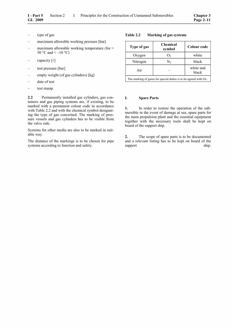
– type of gas
– maximum allowable working pressure [bar]
– maximum allowable working temperature (for > 50 °C and < –10 °C)
– capacity [ ]
– test pressure [bar]
– empty weight (of gas cylinders) [kg]
– date of test
– test stamp
2.2 Permanently installed gas cylinders, gas con-tainers and gas piping systems are, if existing, to be marked with a permanent colour code in accordance with Table 2.2 and with the chemical symbol designat-ing the type of gas concerned. The marking of pres-sure vessels and gas cylinders has to be visible from the valve side.
Systems for other media are also to be marked in suit-able way.
The distance of the markings is to be chosen for pipe systems according to function and safety.
Table 2.2 Marking of gas systems
Type of gas Chemical symbol Colour code
Oxygen O2 white Nitrogen N2 black
Air – white and black
The marking of gases for special duties is to be agreed with GL.
I. Spare Parts
1. In order to restore the operation of the sub-mersible in the event of damage at sea, spare parts for the main propulsion plant and the essential equipment together with the necessary tools shall be kept on board of the support ship.
2. The scope of spare parts is to be documented and a relevant listing has to be kept on board of the support ship.
I - Part 5 GL 2009
Section 2 Principles for the Construction of Unmanned Submersibles Chapter 3Page 2–11
I

Section 3
Design and Construction of Unmanned, Remotely Operated Submersibles (ROV)
A. General Principles
1. Unmanned, remotely operated submersibles (ROVs) are during the mission physically connected to the relevant support ship (e.g. by an umbilical) and are controlled from board of the support ship. As an exception also wireless remote control is possible.
The documents to be submitted to GL for approval are defined in Section 2, E.
The required tests and markings are defined in Section 2, F. and G.
If a launcher for the submersible is provided, it is to be considered as part of the total system of the submersi-ble and to be classified/certified together with it.
2. Submersibles are to be so equipped that the operator can be informed about the position and the operating condition of the vehicle.
3. Submersibles which operate with diver sup-port are to be equipped with a TV unit for monitoring the work site and with special protection arrange-ments, which can be actuated from the control stand for the submersible.
4. Due care is to be taken to ensure that inadver-tent movements cannot cause the remotely operated submersible to destroy itself or equipment located at the work site or to become separated from its control and supply lines (e.g. by cable protector).
5. Submersibles are to be so designed and con-structed, that they achieve also a definite condition (e.g. positive buoyancy) even if the control and the energy supply fail.
6. Measures are to be taken to avoid that the submersible gets caught as far as possible. Propellers are to be provided with adequate protection arrange-ments.
7. All possible stability cases of the submersible with minimum and maximum payload NL including all extension components are to be considered in sur-faced and submerged condition.
The centre of gravity is to be located below the centre of buoyancy.
8. Submersibles are to so designed, that their operation causes no inadmissible environmental loads and endangering of the environment will be avoided as far as possible.
B. Materials
1. Materials for unmanned remotely controlled submersibles and their equipment are to be so se-lected, that the vehicle can be safely operated under the defined conditions of the environment and of the missions during the planned life time.
2. Materials are to be suitable for the purpose intended and approved by GL. Concerning special materials for pressure-proof components reference is made to GL Rules for Manned Submersibles (I-5-2), Section 5, B.
3. The production, processing and testing of materials has to follow recognized standards respec-tively according to specifications of the producer which are proven and approved by GL.
4. The quality of the material of components subject to approval is to be demonstrated in a suitable way , see GL Rules for Manned Submersibles (I-5-2), Section 5, Table 5.3.
5. Materials for rigid buoyancy material bodies are to be suitable for the proposed pressure and tem-perature ranges and shall have a low water absorption factor.
6. Lifting cables are to be manufactured and tested according to a recognized standard or according to the GL Rules for Equipment (II-1-4).
7. Materials shall be resistant against influences of the surrounding media as far it is required for the function of the vehicle and another sufficient protec-tion is not possible. In addition materials have to be compatible to each other.
I - Part 5 GL 2009
Section 3 Design and Construction of Unmanned, Remotely Operated Submersibles (ROV)
Chapter 3Page 3–1
B
C. Design Loads
1. Pressure-proof parts of the construction
Reference points for the pressure heads are the water surface and the lower edge of pressure vessels respec-tively of constructional elements. The following pres-sure heads are to be considered.
1.1 Pressure for nominal diving depth
The nominal diving depth NDD [m] is the diving depth for unrestricted operation of the submersible. The no-minal diving pressure NDP [bar] for this depth follows by multiplying the NDD value by 0,101 [bar/m], if not otherwise agreed with GL for special operations.
1.2 Pressure for test diving depth
The test diving depth TDD [m] is the diving depth at which the vessels and apparatus under pressure resp. the equipment are subjected under test conditions after completion or after main repairs and changes. The test diving pressure TDP for the pressure hull is defined in Table 3.1.
1.3 Pressure for collapse diving depth
The collapse diving depth CDD [m] is the decisive depth for the design of the vessels and apparatus under external pressure and at which by computation a col-lapse of components can be expected.
In general the collapse diving pressure CDP is chosen according to Table 3.1. Deviating factors for the collapse diving pressure may be agreed with GL case by case.
1.4 Safety factors
1.4.1 The safety factor S1 of the pressure-proof parts of the construction is the relation test diving pressure TDP according to 1.2 to nominal diving pressure NDP according to 1.1.
1.4.2 The safety factor S2 of Table 3.1 is the rela-tion collapse diving pressure CDP to nominal diving pressure NDP.
The factor S2 shall cover the following uncertainties:
– influences which cannot be covered by the cal-culation procedure
– influences as consequence of manufacturing mis-takes (material failures, manufacturing inaccura-cies, welding mistakes, residual stresses from manufacturing), compare also Annex B.
– negative influences caused by operation (corro-sion deficiencies, unobserved buckling, alternat-ing stressing)
1.5 Time dependent strength characteristics of the material
For the fatigue strength it has to be defined how often the nominal diving depth NDD can be reached. (see 1.6.1.1)
1.6 Pressure vessels and apparatus under pressure
1.6.1 Load cases for pressure vessels
The following three load cases are to be investigated for pressure vessels and apparatus under pressure, which represent an essential part of the submersible.
1.6.1.1 Load case I
The load case I is determined by operational loads:
– nominal diving pressure NDP according to 1.1
– internal pressure
– flow resistance
– wash of the sea
– ice accretion
– loads at emerging
– accelerations from vehicle movements and seaway
– wind loads
– accelerations from collision
– loads from towing, etc.
– loads from propeller shafts
– loads by rudders, fins and propulsion drives
– loads on tanks without additional internal pressure
– local additional loads because of lifting points and supports
Table 3.1 Test diving pressure and collapse diving pressure depending from nominal diving pressure for unmanned submersibles
Nominal diving pressure NDP [bar] 5 1 10 20 30 40 50 60 ≤ NDP < 400 ≥ 400Test diving pressure / nominal diving pressure S1 = TDP/NDP 1,50 1,30 1,20 1,20 1,20 1,20 1,20 1,10
Collapse diving pressure / nominal diving pressure S2 = CDP/NDP 2,20 1,90 1,80 1,75 1,70 1,65 1,60 1,50
1 Minimum nominal diving pressure 5 bar Intermediate values can be interpolated linearly.
Chapter 3 Page 3–2
Section 3 Design and Construction of Unmanned, Remotely Operated Submersibles (ROV)
I - Part 5GL 2009
C
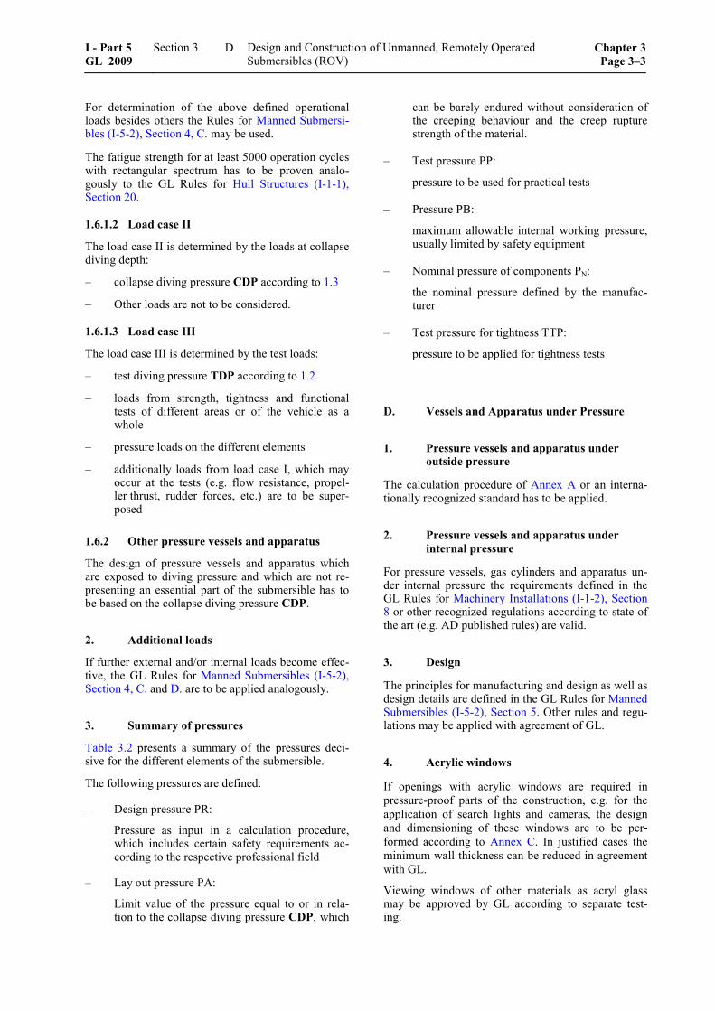
For determination of the above defined operational loads besides others the Rules for Manned Submersi-bles (I-5-2), Section 4, C. may be used.
The fatigue strength for at least 5000 operation cycles with rectangular spectrum has to be proven analo-gously to the GL Rules for Hull Structures (I-1-1), Section 20.
1.6.1.2 Load case II
The load case II is determined by the loads at collapse diving depth:
– collapse diving pressure CDP according to 1.3
– Other loads are not to be considered.
1.6.1.3 Load case III
The load case III is determined by the test loads:
– test diving pressure TDP according to 1.2
– loads from strength, tightness and functional tests of different areas or of the vehicle as a whole
– pressure loads on the different elements
– additionally loads from load case I, which may occur at the tests (e.g. flow resistance, propel-ler thrust, rudder forces, etc.) are to be super-posed
1.6.2 Other pressure vessels and apparatus
The design of pressure vessels and apparatus which are exposed to diving pressure and which are not re-presenting an essential part of the submersible has to be based on the collapse diving pressure CDP.
2. Additional loads
If further external and/or internal loads become effec-tive, the GL Rules for Manned Submersibles (I-5-2), Section 4, C. and D. are to be applied analogously.
3. Summary of pressures
Table 3.2 presents a summary of the pressures deci-sive for the different elements of the submersible.
The following pressures are defined:
– Design pressure PR:
Pressure as input in a calculation procedure, which includes certain safety requirements ac-cording to the respective professional field
– Lay out pressure PA:
Limit value of the pressure equal to or in rela-tion to the collapse diving pressure CDP, which
can be barely endured without consideration of the creeping behaviour and the creep rupture strength of the material.
– Test pressure PP:
pressure to be used for practical tests
– Pressure PB:
maximum allowable internal working pressure, usually limited by safety equipment
– Nominal pressure of components PN:
the nominal pressure defined by the manufac-turer
– Test pressure for tightness TTP:
pressure to be applied for tightness tests
D. Vessels and Apparatus under Pressure
1. Pressure vessels and apparatus under outside pressure
The calculation procedure of Annex A or an interna-tionally recognized standard has to be applied.
2. Pressure vessels and apparatus under internal pressure
For pressure vessels, gas cylinders and apparatus un-der internal pressure the requirements defined in the GL Rules for Machinery Installations (I-1-2), Section 8 or other recognized regulations according to state of the art (e.g. AD published rules) are valid.
3. Design
The principles for manufacturing and design as well as design details are defined in the GL Rules for Manned Submersibles (I-5-2), Section 5. Other rules and regu-lations may be applied with agreement of GL.
4. Acrylic windows
If openings with acrylic windows are required in pressure-proof parts of the construction, e.g. for the application of search lights and cameras, the design and dimensioning of these windows are to be per-formed according to Annex C. In justified cases the minimum wall thickness can be reduced in agreement with GL.
Viewing windows of other materials as acryl glass may be approved by GL according to separate test-ing.
I - Part 5 GL 2009
Section 3 Design and Construction of Unmanned, Remotely Operated Submersibles (ROV)
Chapter 3Page 3–3
D
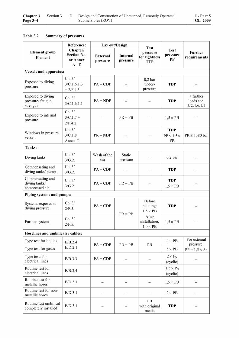
Table 3.2 Summary of pressures
Lay out/Design
Element group Element
Reference: Chapter/
Section No. or Annex
A – E
External pressure
Internal pressure
Test pressure
for tightnessTTP
Test pressure
PP
Further requirements
Vessels and apparatus:
Exposed to diving pressure
Ch. 3/ 3/C.1.6.1.3 + 2/F.4.3
PA = CDP − 0,2 bar under-
pressure TDP −
Exposed to diving pressure/ fatigue strength
Ch. 3/ 3/C.1.6.1.1
PA = NDP − − TDP + further loads acc.
3/C.1.6.1.1
Exposed to internal pressure
Ch. 3/ 3/C.1.7 + 2/F.4.2
− PR = PB − 1,5 × PB −
Windows in pressure vessels
Ch. 3/ 3/C.1.8 Annex C
PR = NDP − − TDP
PP ≤ 1,5 × PR
PR ≤ 1380 bar
Tanks:
Diving tanks Ch. 3/ 3/G.2.
Wash of the sea
Static pressure − 0,2 bar −
Compensating and diving tanks/ pumps
Ch. 3/ 3/G.2.
PA = CDP − − TDP −
Compensating and diving tanks/ compressed air
Ch. 3/ 3/G.2.
PA = CDP PR = PB − TDP
1,5 × PB −
Piping systems and pumps:
Systems exposed to diving pressure
Ch. 3/ 2/F.5.
PA = CDP TDP −
Further systems Ch. 3/ 2/F.5. −
PR = PB
Before painting: 1,5 × PB
After installation:
1,0 × PB 1,5 × PB −
Hoselines and umbilicals / cables:
Type test for liquids 4 × PB
Type test for gases E/B.2.4 E/D.2.1 PA = CDP PR = PB PB
5 × PB
For external pressure:
PP = 1,5 × Δp
Type tests for electrical lines E/B.3.3 PA = CDP − –
2 × PN (cyclic)
−
Routine test for electrical lines E/B.3.4 – – – 1,5 × PN
(cyclic) –
Routine test for metallic hoses E/D.3.1 − − − 1,5 × PB −
Routine test for non-metallic hoses E/D.3.1 − − − 2 × PB −
Routine test umbilical completely installed E/D.3.1 − −
PB with original
media TDP −
Chapter 3 Page 3–4
Section 3 Design and Construction of Unmanned, Remotely Operated Submersibles (ROV)
I - Part 5GL 2009
D
Table 3.2 Summary of pressures (continued)
Lay out / Design
Element group Element
Reference: Chapter/
Section No. or Annex
A – E
External pressure
Internal pressure
Test pressure
for tightnessTTP
Test pressure
PP
Further requirements
Drives and electrical equipment: Cases exposed to diving pressure
Ch. 3/ 3/K.5.1 PA = CDP − TDP − −
Electric penetrations/ Type test
PA = CDP −
With air: 2 × PN
With He: 1,5 × PN
2 × PN (cyclic) −
Electric penetrations/ Routine test
Ch. 2/ 11/D.8. Ch. 3/ 3/K.5.2
− − − 1,5 × PN (cyclic) −
E. Supporting Structure and Exostructure, Equipment
1. Supporting structure
1.1 Frames and supporting structures of sub-mersibles are to be designed and constructed accord-ing to state-of-the-art technology.
1.2 Approved methods of calculation are to be applied to the design of the supporting structure. The structure is to be dimensioned in such a way that at the anticipated loads the effective stress does not exceed 60 % of the yield strength.
1.3 The supporting structure of the submersible is to be designed to avoid unintentional trapping of the structure.
1.4 The lifting points on the submersible is to be so designed and located that the launching and recov-ering is possible for the maximum permissible seaway conditions and the maximum weight. The lifting points shall have a safety against rupture of 8 times the working load and are to be clearly signed and marked with their working load.
1.5 The umbilicals connection of the submersible has to be designed to transfer the maximum permissi-ble tension load of the umbilical to the supporting structure.
1.6 If in case of failure a recovery of the sub-mersible is not possible, elements for fastening towing lines are to be installed on the submersible. This tow-ing point is to be so designed and located that the submersible can be towed surfaced even under most unfavourable operating conditions with the maximum planned towing speed.
2. Exostructure
2.1 If the submersible shall achieve a consider-able speed worth mentioning, the exostructure is to be provided with streamlined and smooth surface. Step-wise connections of structural elements shall be equal-ized if the flow will be influenced in a negative way.
2.2 The exostructure at the underside of the sub-mersible is to be designed to ensure sufficient protec-tion against interference of the sea bottom in case of impact of the vehicle.
– As far as necessary, submersibles are to be equipped with ram frames or similar to protect components and working devices.
– If a combination of the submersible with a launch-er and/or a garage is provided, the exostructure is to be so designed that a safe guidance into and out of the launcher/garage as well as a safe protection against canting and getting caught is guaranteed.
2.3 All free floodable areas of the exostructure are to be designed in a way and provided with openings that complete flooding/exhausting resp. ventilating/ emptying of the spaces is guaranteed and it is also to be considered, that no impermissible loads are caused by eventual pressure differences.
2.4 Buoyancy material appliances mounted ex-ternally on the vehicle are to be properly secured and protected.
2.5 All flaps in the exostructure have to be flush, safely closable and secured against vibrations.
3. Equipment
According to the area of operation and the purpose of the mission of the submersible, the required elements of the hull equipment are to be provided:
I - Part 5 GL 2009
Section 3 Design and Construction of Unmanned, Remotely Operated Submersibles (ROV)
Chapter 3Page 3–5
E
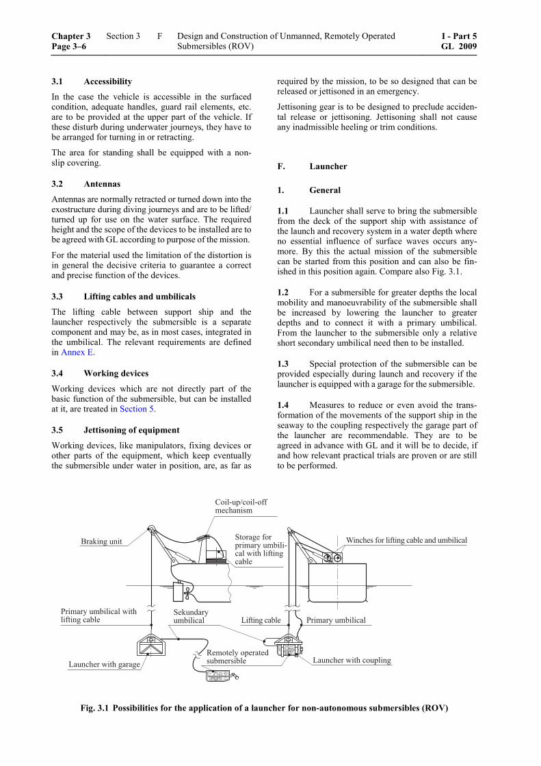
3.1 Accessibility
In the case the vehicle is accessible in the surfaced condition, adequate handles, guard rail elements, etc. are to be provided at the upper part of the vehicle. If these disturb during underwater journeys, they have to be arranged for turning in or retracting.
The area for standing shall be equipped with a non-slip covering.
3.2 Antennas
Antennas are normally retracted or turned down into the exostructure during diving journeys and are to be lifted/ turned up for use on the water surface. The required height and the scope of the devices to be installed are to be agreed with GL according to purpose of the mission.
For the material used the limitation of the distortion is in general the decisive criteria to guarantee a correct and precise function of the devices.
3.3 Lifting cables and umbilicals
The lifting cable between support ship and the launcher respectively the submersible is a separate component and may be, as in most cases, integrated in the umbilical. The relevant requirements are defined in Annex E.
3.4 Working devices
Working devices which are not directly part of the basic function of the submersible, but can be installed at it, are treated in Section 5.
3.5 Jettisoning of equipment
Working devices, like manipulators, fixing devices or other parts of the equipment, which keep eventually the submersible under water in position, are, as far as
required by the mission, to be so designed that can be released or jettisoned in an emergency.
Jettisoning gear is to be designed to preclude acciden-tal release or jettisoning. Jettisoning shall not cause any inadmissible heeling or trim conditions.
F. Launcher
1. General
1.1 Launcher shall serve to bring the submersible from the deck of the support ship with assistance of the launch and recovery system in a water depth where no essential influence of surface waves occurs any-more. By this the actual mission of the submersible can be started from this position and can also be fin-ished in this position again. Compare also Fig. 3.1.
1.2 For a submersible for greater depths the local mobility and manoeuvrability of the submersible shall be increased by lowering the launcher to greater depths and to connect it with a primary umbilical. From the launcher to the submersible only a relative short secondary umbilical need then to be installed.
1.3 Special protection of the submersible can be provided especially during launch and recovery if the launcher is equipped with a garage for the submersible.
1.4 Measures to reduce or even avoid the trans-formation of the movements of the support ship in the seaway to the coupling respectively the garage part of the launcher are recommendable. They are to be agreed in advance with GL and it will be to decide, if and how relevant practical trials are proven or are still to be performed.
����������
��� ��� �����������������������
�������� ������� ������������ ��� ��� �������
�������������������� ��������������� �������
������������������������� �������
������ �������� �������
������������� ��� ������������������������
�����������������
Fig. 3.1 Possibilities for the application of a launcher for non-autonomous submersibles (ROV)
Chapter 3 Page 3–6
Section 3 Design and Construction of Unmanned, Remotely Operated Submersibles (ROV)
I - Part 5GL 2009
F
2. Basic requirements
2.1 The suspension of the launcher is to be so designed that a turning of the launcher and, if existing, also of the garage will be reduced as this would render the recovery of the submersible more difficult.
2.2 If the launcher is suspended on the launch and recovery device suitable measures are to be taken against excessive swinging caused by ship move-ments.
2.3 If no garage for the submersible is provided, the submersible is to be suspended with a suitable coupling device under the construction of the launcher. Adequate guidance devices to the coupling points are to be installed on the launcher. Concerning the successful coupling and decoupling procedures including locking a feedback signal is required to the control stand on the support ship.
2.4 For the umbilical winch on the launcher the same requirements as defined for the winches on the support ship are valid analogously.
2.5 To facilitate the control and monitoring of the procedures for start and recovery of the submer-sible and also to be able to overlook and check the surrounding area of the launcher an illumination sys-tem and adequate video cameras are to be installed. This can also be safeguarded by other suitable meas-ures.
2.6 For the equipment for acoustic position find-ing the same requirements as defined for devices on submersibles are valid.
2.7 For the equipment like hydraulic systems and electrical installations the same requirements as for submersibles are valid.
3. Garage
If the launcher is equipped with a garage, the follow-ing requirements are to be met:
– The supporting structure of the cage shall be adequately robust to be able to endure impacts and is to be equipped with fenders if need be. For the requirements on statics the definitions in D.1. and D.2. are valid in analogous form.
– Adequate guidance devices or other aids for parking (e.g. sensors) are to be provided to faci-litate the parking of the submersible in the ga-rage.
– After the complete entrance in the garage the submersible is to be interlocked/before the exit it is to be unlocked. About these procedures a feedback signal to the control stand on the sup-port ship is required.
G. Piping Systems and Umbilicals
Piping systems include pipe lines, fittings, hoses, pumps and compressors.
1. General
1.1 Piping systems are to be designed and in-stalled according to internationally recognized stan-dards. For the selection of the material, manufacturing and computation the GL Rules for Machinery Installa-tions (I-1-2), Section 11 can be applied, as far as ap-plicable.
1.2 Piping systems are to be dimensioned for a design pressure PR equal to the maximum allowable working pressure PB.
All piping systems which may be loaded with the diving pressure are to be designed additionally for 1,0 times the collapse diving pressure CDP (according to the load case from outside or inside).
2. Piping systems
2.1 Piping systems which may be exposed to pressures above the design pressure are to be provided with an overpressure protection which guarantees a safe blowing-off.
2.2 Piping systems for gases and electric cables are to be installed separately. Piping systems which are endangered to mechanical damage are to be pro-tected.
3. Fittings
3.1 Shut-off devices shall conform to a recog-nized standard. Fittings with screw-down covers and spindles are to be safeguarded against accidental un-screwing of the cover or of the spindle.
3.2 Manual shut-off devices are to be closed by turning in the clockwise direction. The open and closed positions of essential shut-off valves are to be clearly recognizable. If they have to be operated by a diver under water they are to be so designed that the handling is possible while wearing mittens.
3.3 Fittings for hoses are to be made of corrosion resistant material and are to be so designed that unin-tentional loosing can be excluded.
4. Hose assemblies
As far as the requirements of 6. are relevant for hose assemblies, they shall be applied.
5. Pumps and compressors
The casing of pumps and compressors are to be pro-vided pressure proof. The proof of strength shall be
I - Part 5 GL 2009
Section 3 Design and Construction of Unmanned, Remotely Operated Submersibles (ROV)
Chapter 3Page 3–7
G
done by computation. If this is only possible in an insufficient way, these casings are to be tested accord-ing to the requirement of GL.
6. Umbilicals
Umbilicals as connecting element between support ship/launcher and launcher/submersible may contain hydraulic and pneumatic pipes within a joint encasing.
All aspects for the design of umbilicals are treated in Annex E.
7. Compressed air systems
7.1 Compressed air systems which come in con-tact with seawater are to be designed adequately and to be separated from other systems. In addition meas-ures are to be taken to exclude the entrance of sea-water in the compressed air system as far as possible.
7.2 Compressed air systems are to be equipped with pressure indicators. Maximum working pressures are to be marked.
8. Hydraulic systems
8.1 The pressure creating and distribution compo-nents of the hydraulic systems have to have adequate performance if the manoeuvring systems are hydrauli-cally driven. In addition it has to be defined if and how much additional capacity for working devices to be connected (compare Section 5) is to be made available.
8.2 If the hydraulic aggregate is located on the launcher, an adequate electrical feeding via the um-bilical is to be provided. A supply with higher voltage and subsequent voltage transformation to a lower voltage is permissible.
8.3 Concerning selection of materials, manufac-turing and computation the GL Rules for Machinery Installations (I-1-2), Section 14 are valid.
H. Arrangements for Control resp. Adjust-ment of Depth, Trim, Positive and Nega-tive Buoyancy
1. Unmanned, remotely operated submersibles are to be provided with arrangements for control re-spectively adjustment of depth, positive and negative buoyancy. It has to be secured that these arrangements are effective under all specified conditions of heel and trim.
2. Depending on the type of submersible the following systems may be regarded as arrangements for control and support of depth, trim, positive and negative buoyancy:
– lifting cable if the submersible is connected tight with it
– releasable weights (for quick diving to a wanted depth resp. for emerging)
– fixed resp. adjustable ballast and trimming weights
– rigid buoyancy appliances, e.g. of pressure resis-tant foam
– floodable ballast and trim tanks
– propeller drives
– depth rudders with dynamic effects (e.g. for towed submersibles)
3. The control devices are to be capable of compensating the expected differences in water den-sity and of ensuring that the submersible attains a defined diving state.
The submersible has to be stabile in each operational phase and be in the position to return to the water surface.
4. The arrangements for control of depth, trim, positive and negative buoyancy are to be controlled from the control stand of the submersible on the sup-port ship. In addition the depth of the submersible has to be indicated continuously on the console.
I. Propulsion and Manoeuvring Equipment
1. Propulsion equipment
1.1 With regard to their type, number, size and arrangement, propulsion devices shall be designed to meet the requirements arising from the planned pur-pose and location of the mission.
1.2 Propulsion units shall be designed for the collapse diving pressure CDP or shall be pressure-balanced.
1.3 Propulsion plants for submersibles are to be designed for intermittent and continuous operation.
1.4 Electric propulsion motors are to be designed in accordance with the requirements of L.
1.5 Shaft penetrations and other penetrations through the wall of pressure vessels are to be provided with a proven seal designed for the collapse diving pressure CDP.
1.6 Propellers are to be so arranged that an unin-tentional trapping of the submersible or getting caught of the umbilical or lifting cable can be largely ex-cluded. For a joint mission with divers the propellers are to be protected against unintentional approach, e.g. by ducting and grids or nets before and aft.
Chapter 3 Page 3–8
Section 3 Design and Construction of Unmanned, Remotely Operated Submersibles (ROV)
I - Part 5GL 2009
I
1.7 Devices for controlling the speed and/or the direction of the rotation are to be so designed that the propulsion motor can be stopped even in the event of their failure.
1.8 The operating condition of the propulsion units (direction of thrust and rotation) has to be dis-played at the control stand on the support ship.
2. Manoeuvring equipment
2.1 Remotely operated submersibles are to be equipped with suitable devices which provide the vehicle with the required manoeuvrability under con-sideration of the most unfavourable operating condi-tions. Especially also a propeller thrust for going backwards is to be provided which enables an effec-tive braking of the vehicle.
2.2 Depth and side rudder devices are to be de-signed for the greatest loads which result at underwa-ter journeys from the steering forces resp. at planned longer surface journeys from pitching movements and wash of the sea. The equivalent stress in the rudder shaft shall not exceed 0,5 × yield strength.
2.3 Depth rudders are to be so designed that the wanted depth can be kept in the assigned speed range and under all load conditions.
2.4 For the swivelling devices of the propulsion units, which serve at the same time as manoeuvring device, the same requirements are valid as for rudders.
3. Mission on the bottom of the sea
3.1 If the movement happens on wheels or crawl-ers, their foot print area is to be adjusted to the practi-cally possible bottom pressure in the planned mission area. Design and drive are to be agreed with GL case by case.
3.2 At sandy or muddy bottom of the sea propul-sion units which are used for the advance shall not be positioned too low or shall be totally avoided as the visibility around the vehicle can be strongly limited because of the whirled up bottom material.
3.3 Systems for locating of obstacles, like rocks, wrecks, pipelines, offshore structures, etc. are to be provided to avoid collisions safely.
J. Positioning System
Dynamic positioning may be required for certain pur-poses of operation, especially for remote controlled submersibles a cooperation with the support ship may be required, compare also Section 6, C.4.
1. General
1.1 Dynamic positioning means that a vehicle keeps automatically its position at the water surface or in the underwater space (within accuracy of the sys-tem defined for the duty of the mission) or that it moves on a predefined track, using solely the effect of propulsors.
1.2 Systems for dynamic positioning have to include the following subsystems:
– as far as required for safe operation redundant source of energy with switchgear and energy distribution
– a number of drives/propulsors with motor and, if necessary, gear as well as propeller, eventually slewing gear; the control of the positioning sys-tem has to be adequate to the purpose of the mission of the submersible
– suitable sensors for determination of loca-tion/position
– control system including computer system with software, monitoring display at the control stand and reference system for the position
– Further details concerning the requirements for such systems are defined in the GL Rules for Dynamic Positioning (I-1-15).
2. Submersible
For submersibles the use of dynamic positioning and the required equipment for this has to be agreed with GL case by case.
K. Working Devices
1. Only working devices are to be applied to submersibles if the influence on the total system is investigated and approved by GL.
2. Working devices are to be so arranged on the submersible that it can get largely excluded to trap the vehicle or that the umbilical or the lifting cable be-come entangled.
3. Fixing systems are to be designed and con-structed that a defined holding power can be adjusted. In addition devices should to be provided with which the holding claw or similar can be opened in case of energy failure.
4. Concerning all further requirements for work-ing devices respectively for their separate Certification see Section 5.
I - Part 5 GL 2009
Section 3 Design and Construction of Unmanned, Remotely Operated Submersibles (ROV)
Chapter 3Page 3–9
K
L. Electrical Equipment
1. Principles
1.1 All electrical equipment is to be so designed and installed that it is operational and serviceable under the design conditions specified for the remotely operated submersible.
1.2 Systems for which even a brief failure cannot be tolerated are to be provided with battery support or are to be supplied by an uninterruptible power.
1.3 Where batteries are used, eventually the spe-cial operating conditions are to be observed. Battery chargers shall have a characteristic conforming to the battery manufacturer's recommendations.
2. Power supply
2.1 Principles
2.1.1 Devices are to be provided enabling the sub-mersible to be voltage-absent during launching and recovery.
2.1.2 Approved supply systems are:
– direct current and single-phase alternating cur-rent, with both conductors insulated from the hull of the submersible
– three-phase alternating current with the three conductors insulated from the hull of the sub-mersible, networks with an earthed neutral are not permitted.
2.1.3 The permissible voltage and frequency devia-tions stated in the Rules for Classification and Con-struction for Electrical Installations (I-1-3), Section 1 shall not be exceeded.
2.2 Main power supply
2.2.1 A power balance shall be prepared to prove that the rating of the main power supply is sufficient.
2.2.2 Appropriate diversity factors may be assumed for consumers which are intermittently connected.
2.2.3 A power margin is to be provided for tran-sient peak loads (e.g. on motor start-up).
2.2.4 A subordinate mistake shall not hinder the distribution of sufficient power for the drive of the vehicle or other essential systems, like search lights and video cameras.
2.3 Emergency power supply
2.3.1 An emergency energy supply is necessary in those cases where the endangerment of the submersi-
ble, its environment or its function due to a failure of the main power supply is inadmissible.
2.3.2 The emergency power supply is to be so designed that, if the main power supply fails, the sub-mersible can be brought in a stationary operating con-dition which at no time presents a danger. From this condition it shall be possible either to recover the vehicle safely or to continue its mission after the main power supply has been restored.
3. Power distribution
3.1 Electrical distribution systems are to be so designed that a fault or failure in one circuit does not impair the operation of other circuits.
3.2 During normal operation the emergency power distribution system may be fed via an intercon-nector feeder from the main power distribution sys-tem.
3.3 The lengths of cables from storage batteries to the switchboard/switching devices and end con-sumers are to be kept as short as possible. These ca-bles are to be laid separately to the corresponding circuit-breaker and are to be specially protected against mechanical damage.
3.4 In switchgears, measures are to be taken for the prevention of parasitic voltages. Voltage circuits for safety extra low voltage shall not be run in the same conductor bundle or in the same cable duct as higher-voltage circuits. Terminals for different voltage levels are to be arranged separately and marked ac-cordingly.
4. Protective measures
4.1 Each circuit is to be protected against short circuit and overload.
4.2 All consumer circuits are to be designed for all-pole switching.
4.3 If remotely operated submersibles operate with diver support, electrical systems whose failure could endanger the divers are to be designed for high availability, e.g. with battery back-up.
4.4 Where remotely operated submersibles oper-ate with diver support, a continuous insulation-monitoring system is to be provided which actuates a visual and audible alarm at the ROV control station when the value drops below a minimum level. Where the possibility of danger to humans cannot be ruled out, provision is to be made for the automatic discon-nection of the circuit concerned.
An emergency stop device for the submersible is to be installed at the control stand. It shall be designed to exclude unintentional actuation, compare Section 6.
Chapter 3 Page 3–10
Section 3 Design and Construction of Unmanned, Remotely Operated Submersibles (ROV)
I - Part 5GL 2009
L
4.5 Remotely operated submersibles with electri-cal equipment are to be provided with an earthing and equipotential system. All non-current-carrying metal parts are to be connected to this.
Where earthing is not provided via the fastenings, protective conductors are to be fitted.
Where protective conductors are used, the following is to be observed:
a) The protective conductor has to take the form of an additional cable or additional line or an addi-tional core in the power cable. The use of ar-mouring as protective conductors is to be checked case by case and to be approved by GL.
b) A conductor which carries current in normal operation shall not simultaneously be used as a protective conductor and shall not be connected jointly with the latter to the hull of the vehicle.
c) The cross-section of the protective conductor shall be equivalent to at least half the cross-section of the phase conductors. However, with cross-sections of up to 16 mm² the cross-section shall be the same as that of the phase conductor. With separately laid protective conductors the minimum cross-section is 4 mm2.
d) The connections of the protective conductors shall be installed at locations which can be eas-ily checked.
e) In an easily accessible position on the hull of the submersible a connection point in the form of a connecting plate with preferably M 12 stud bolts is to be provided to which, a protective conduc-tor can be connected without the use of tools. This connection serves for the compensation of the potential between the recovered submersible and the support ship.
f) Depending of the endangering potential of the electrical plant of the submersible a device for compensation of the potential is to be provided which is already effective during recovery out of the water.
5. Electrical equipment
5.1 The housings of non-pressure-compensated electrical equipment for underwater use are to be de-signed for the collapse diving pressure CDP as a minimum.
5.2 Penetrations in vessels and plug-and-socket connections are to be designed and tested in accor-dance with the GL Rules for Manned Submersibles (I-5-2), Section 11, D.8. under consideration of 5.1.
5.3 For electrical equipment a minimum type of protection IP 44 is required.
5.4 Insulation class F is to be provided for the windings of electrical machines.
5.5 Underwater cables and lines shall be imper-vious to transverse water penetration (i.e. no water shall penetrate the sheath) and are to be designed for an overpressure which is equivalent to the collapse diving pressure CDP. For further requirements con-cerning design and testing see Annex E.
5.6 Drum cables are to be so designed that me-chanical forces are not transmitted via electrical com-ponents.
5.7 For monitoring of the manoeuvres and activi-ties of the ROV under water suitable searchlights and video cameras are to be provided.
M. Control, Automation, Data Transfer, Navigation and Locating Equipment
1. Design principles
1.1 General principles
1.1.1 All devices for automatically monitoring and controlling the operating parameters of a submersible are to be so designed and constructed that they func-tion properly under the design and ambient conditions laid down for the vehicle.
1.1.2 Computer-aided operational control systems for the submersible are permissible. Details of the scope and redundancy of the equipment are to be agreed with GL.
The systems are to be approved by GL and type ap-proved components should be used. The check con-tains the applied devices (hardware) as also the effec-tiveness of software programs belonging to them. Kind and scope of the check is to be agreed with GL.
1.1.3 Computer-aided operational control systems are to be capable of being switched to manual opera-tion at any time. Exceptions to this rule are to be agreed with GL.
1.1.4 No fault or failure whatsoever in the automa-tion system shall lead to an uncontrollable operating condition.
1.1.5 Automation equipment shall be as far as possible protected against incorrect operation.
1.1.6 Automation equipment shall be capable of maintaining the pre-defined operating parameters of the submersible.
1.1.7 All inadmissible deviations from the operat-ing parameters shall automatically actuate a visual and audible alarm at the control station, this applies addi-tionally to automatic changeovers in the power supply system and to faults in the control and monitoring system.
I - Part 5 GL 2009
Section 3 Design and Construction of Unmanned, Remotely Operated Submersibles (ROV)
Chapter 3Page 3–11
M
1.1.8 In addition to electronic control and monitor-ing devices, independent safety devices are to be pro-vided which prevent a fault in a system from creating an unsafe or undesirable operating condition.
1.1.9 The response settings of automation devices are to be co-ordinated in such a way that, when a limit value is reached, an indicating signal is actuated fol-lowed by the response of the safety devices on the expiry of a specific warning period or on the further variation of the process variable at a preset speed.
1.1.10 The overall behaviour of the automation equipment has to be compatible with the time con-stants of the devices and components in the system.
1.1.11 As criterion for the noise immunity of elec-tronic systems the IEC standard 60533 (Electromag-netic compatibility of electronic installation in ships) is to be applied.
1.2 Construction
1.2.1 Electronic automation equipment shall com-prise easily interchangeable modules using the plug-in system wherever possible. The modules should be largely standardized, and the number of module types should be kept small to reduce the spares inventory.
1.2.2 Plug-in cards shall be clearly marked or coded as a safeguard against accidental confusion.
1.2.3 Measures are to be taken to prevent conden-sation inside electronic equipment even when it is switched off. A stand-by heating is recommended.
1.2.4 Wherever possible, automation equipment shall be preferably operable without forced ventila-tion.
The functioning of any cooling system is to be moni-tored.
1.2.5 Components are to be effectively fastened. The mechanical loading of wires and soldered connec-tions by vibrations and shaking is to be minimized.
1.2.6 The construction of systems and equipment shall be simple and straightforward. Easy accessibility for measurements and repairs is desirable.
1.3 Circuitry
1.3.1 Signalling, monitoring and control devices for safety-related functions are to be constructed on the fail-safe principle, i.e. defects such as short-circuits, earth faults and breaks cannot produce condi-tions endangering humans or equipment. This is to be based on the assumption of single faults.
The failure of one module, e.g. due to short-circuit, shall not result in damage to other modules.
1.3.2 In programmable controllers the electrical values of the sensors shall meet the safety require-ments for control devices. This means primarily:
– H-level start-up, i.e. by powering via NO con-tacts
– L-level shutdown, i.e. by de-powering via NC contacts
The requirements stated in 1.3.1 are unaffected.
1.3.3 Command and control devices for safety functions, e.g. emergency-stop sensors, are to be inde-pendent of a programmable controller and are to act directly on the output device, e.g. stop solenoid valve. They are to be safeguarded against unintentional op-eration.
1.3.4 Programmable controllers shall be non-interacting and in case of fault shall not cause distur-bances in program-independent safety interlocks and safety switching sequences for fixed subroutines.
1.3.5 Freely accessible potentiometers and other components provided for adjustment or working-point setting are to be capable of being locked in the operat-ing position.
1.3.6 Switchgear interfaces are to be so designed that contact chatter has no adverse effects on the op-eration of the equipment.
1.3.7 Printed conductors forming part of circuits extending outside the enclosure containing the printed circuit boards are to be conditionally short-circuit proof, i.e. in the event of an external short-circuit only the protective devices provided may respond without destroying the printed conductors.
1.3.8 The equipment shall not be damaged by brief voltage surges in the vehicle's power supply which may be caused by switching operations. If not more detailed otherwise at the feeding of the remotely oper-ated submersible wiring-bound interference voltages and quick transient interference factors according to IEC 61000-4-5, severity level 3 are to be considered.
Where equipment is supplied from static converters, allowance is to be made for periodic voltage pulses. The amplitude depends on the type of converter and is to be investigated in each case.
An overvoltage protection adjusted to the equipment is recommended.
1.4 Power supply
1.4.1 For the supply of control, monitoring and safety systems - in general by the support ship - the requirements according to the GL Rules for Electrical Installations (I-1-3), Section 9 are to be observed, com-pare also Section 6.
1.4.2 The power supply is to be monitored and a failure is to be alarmed and registered.
Chapter 3 Page 3–12
Section 3 Design and Construction of Unmanned, Remotely Operated Submersibles (ROV)
I - Part 5GL 2009
M
1.4.3 Power supply units for automation equipment shall at least have short-circuit and overload protection as far no unsafe operating condition of the vehicle can be created by these.
1.4.4 Automation equipment is to be capable of reliable operation with the voltage and frequency deviations mentioned in the GL Rules for Electrical Installations (I-1-3), Section 1.
2. Control station
2.1 For monitoring and controlling the submersi-ble a control station or console is to be provided aboard of the support ship (in a mobile container or permanently installed in the support ship) at which all the important data relating to the vehicle are displayed and all the controls and monitors, including TV and communications facilities, are located which are needed for the operation of the submersible.
2.2 The instruments for supervising, open and closed loop control and operating of the submersible are to be grouped and arranged on ergonomic princi-ples at the control stand.
2.3 All monitoring and control devices are to be unambiguously labelled and marked.
2.4 Limit values are to be marked for analogous measuring instruments. In case of reaching limit val-ues on digital indicating instruments an alarm is to be provided.
2.5 As far as feasible and rational, initiated con-trol functions are to be indicated optically at the con-trol station.
2.6 In the area of the control station no plants or systems are to be installed which are impairing the supervision and operation of the submersible.
2.7 The prerequisites which are to be made avail-able for the control station by the support ship are defined in Section 6.
3. Sensors and actuators
All devices for registering the operating conditions of remotely operated submersibles as well as the belong-ing actuators are to be approved by GL and should be type tested.
4. Data transfer systems
4.1 For the use of data cables it has to be guaran-teed that the specified data volume per time unit will be transmitted without disturbances under all operat-ing conditions.
4.2 In case of a failure of the data transfer the submersible has to reach a defined and safe operating condition.
4.3 If secondary "data for payloads" shall be transferred with data lines, these are to be transmitted independently from the data lines for the operation of the submersible.
5. Navigation and locating equipment
Principally also the regulations of the flag state re-spectively of the competent authorities are to be con-sidered.
5.1 All the electronically operated navigation and locating equipment necessary to the safety of the sub-mersible is to be connected to the submersible's emer-gency power supply. Its operational or stand-by status is to be clearly indicated at the control station.
5.2 As far as it is feasible and rational, remotely operated submersibles should be equipped with an automatic emergency locating device (pinger). If a launcher is provided, it can be favourable to equip it also with an emergency locating device (pinger). These locating devices are to be harmonized with those on the support ship.
5.3 Submersibles are to be equipped with suitable signal systems (e.g. flashing light), which enable a quick detection of the surfaced submersible.
5.4 For better visibility of the submersible at the water surface, submersibles should be provided with contrast colour painting or reflection material, apply-ing preferably the colours orange, yellow or red.
N. Fire and Explosion Protection
Especially if the submersible is on board of a support ship where there are explosion endangered areas, adequate explosion protection measures are to be provided for the equipment and the control stations of the submersible; if need be the equipment is to be checked specially and marked for this type of mission.
O. Operational Media
1. Operational media such as hydraulic fluids, lubricants, etc. are to be selected in accordance with the proposed ambient conditions. They shall not tend to congeal or evaporate over the whole temperature range.
2. Operational media are to be so selected that water penetration resp. mixing with seawater does not essentially impair the functionality of the submersible.
I - Part 5 GL 2009
Section 3 Design and Construction of Unmanned, Remotely Operated Submersibles (ROV)
Chapter 3Page 3–13
O
3. Operational media shall not contain toxic ingredients which are liable to be hazardous to health through skin contact or when given off in fumes.
4. Operational media should not be corrosive or attack other operating equipment (e.g. seals, hose lines, etc.).
P. Corrosion Protection
Submersibles and all adjacent components are to be protected effectively against corrosion. Further in-formation can be gained from the GL Guidelines for Corrosion Protection and Coating Systems (VI-10-2).
Chapter 3 Page 3–14
Section 3 Design and Construction of Unmanned, Remotely Operated Submersibles (ROV)
I - Part 5GL 2009
P
Section 4 Additional Requirements for Unmanned, Autonomous Submersibles (AUV)
A. General Principles
1. In principle the requirements of the Sections 1 – 3 are besides this Section also valid for the design and construction of autonomous submersibles (AUV) as far as applicable.
Unmanned autonomous submersibles (AUV) are to be equipped with own power supply and own open and closed loop control including eventual control by ac-tive and/or passive sensors and computer hard- and soft-ware, to fulfil predefined missions in autonomous way for a certain time period. Afterwards they are recov-ered by a support ship and are supplied, maintained and transferred to the location of the next mission.
2. The tasks of the AUV serve mainly for the execution of missions for surveillance, observation, measurements, making films, cartographic records, etc. Other tasks are possible as far as the power de-mand can be covered by the AUV.
3. For a simultaneous mission of several AUVs from one support ship, the additional requirements will be defined by GL case by case.
4. AUVs which are connecting at the working place to a supply line and are then operated as ROV are designated as Hybrid-ROV (HROV).
The special conditions for such a case of application will be defined by GL case by case.
5. As far as applicable, the requirements of this Section may be applied also for measuring devices and measuring sensors, which are used stationary or mobile without own propulsion.
B. Principles of Design and Construction
1. Design principles
For autonomous submersibles in general the following design principles are to be realized:
– power supply of sufficient capacity for the de-fined scope of tasks
– sensor system which allows a three dimensional positioning in the underwater space
– computer equipment for programming of missions
– emergency program to abandon the mission if failures occur and to enable the recovering of the vehicle
A deviation from single requirements may be agreed with GL.
2. Supporting structure
The supporting structure may be provided e.g. as pres-sure hull with adequate watertight closable openings or as basic structure with pressure vessels arranged in be-tween. Other types of structure may be agreed with GL.
3. Launcher
For autonomous submersibles the application of launchers without and with garage for the safe launch and recovery should be possible, compare Fig. 4.1. The requirements for the launcher are equivalent to those defined in Section 3, F., as far as applicable.
4. Equipment for control respectively adjust-ment of depth, trim, positive and negative buoyancy
4.1 Weights For solely application of weights which can be re-leased adequately, the following functions have to be clearly separated:
– equipping with oversized weights for quick diving to the required depth
– partial release of weights to achieve floating in the water (smaller density differences of the wa-ter, etc. can be equalized dynamically)
– further release of weights for emerging at the end of mission
4.2 Cells If diving tanks, compensating tanks and trimming tanks are provided for bigger AUVs, systems analogous to manned submersibles are to be provided, but simpler measures with reduced redundancy may be applied.
4.3 Dynamic arrangements
Arrangements are to be provided for:
– keeping a certain diving depth on the one hand, or – achieving on the other hand a certain distance
from the sea bottom, even it is uneven or rugged.
The tolerances for these characteristics are to be de-fined by the manufacturer and are to be checked at the trials according to D.
I - Part 5 GL 2009
Section 4 Additional Requirements for Unmanned, Autonomous Submersibles (AUV)
Chapter 3Page 4–1
B
����������
� ����������������������� ������������ � �������
������������������
������������������������� �������
��������������� �������
���������� �����������������������
���������������������� ���� �������
Fig. 4.1 Application of launchers for autonomous submersibles (AUV)
4.4 Automatic depth limitation
For missions of an AUV in waters, which are deeper than nominal diving depth NDD, an automatic depth limitation is required.
4.5 Emergency surfacing systems
To avoid the total loss of the submersible, e.g. in case of total power failure, an energy independent emer-gency surfacing system is recommended.
As emergency surfacing systems e.g. weights with corrosion fastening or gas operated surfacing systems may be applied.
5. Propulsion and manoeuvring equipment
The propulsion and manoeuvring equipment may include:
– propeller main propulsion with single propeller or contra-propeller with reverse direction of ro-tation resp. water jet propulsion
– steering propeller, especially for assistance of changes of diving depth
– horizontal and vertical effective fins and rudders
6. Electrical equipment
6.1 Principles
The time of functioning of the electrical equipment is to be specified according to the maximum duration of the missions of the AUV.
6.2 Power supply
6.2.1 A main power supply has to be provided, which will be in general a battery.
6.2.2 In addition an emergency power supply has to be provided which shall supply the following sys-
tems for a period of time to be specified, but at least for 24 hours:
– emergency processor for activation of the emer-gency measures
– performing of the emergency measures (e.g. controlled emerging, release of a signal shape)
– dispatch of wireless signals
– flash light or other lights if required and possi-bly acoustic signals
6.2.3 Depending on the potential of danger for the electrical equipment of the AUV a device to equalize the potential is to be provided which is already effec-tive during recovery from the water.
7. Automation, navigation and location sys-tems
7.1 Automation
7.1.1 Pre-programmed missions are to be entered and stored. The execution has to begin after a starting order.
7.1.2 During the execution of the mission, its per-formance according to program has to be checked by suitable routines and if necessary be corrected. The essential mission parameters are to be recorded.
7.1.3 A series of parameters which are concerning the operation of the AUV directly and which are essential for it are to be monitored and eventually a failure report is to be sent to the support ship. If the transmission is not possible for some time, all reports are to be stored for reconstruction of the function of the AUV at the end of the mission. Such parameters can inter alia be:
– specific status reports, e.g. position, speed, div-ing depth, etc.
– ground fault of the electric equipment
Chapter 3 Page 4–2
Section 4 Additional Requirements for Unmanned, Autonomous Submersibles (AUV)
I - Part 5GL 2009
B
– voltage drop
– over temperature of monitored components
– entrance of water in a monitored space
– overpressure in a monitored space
– failure of the main computer
7.1.4 If the detected failures according to 7.1.3 can-not be corrected and if the following problems arrive:
– exceeding of the nominal diving depth,
– leaving of the area defined for the mission,
– exceeding of the period of time for the mission,
the mission has to be broken-off and the provided emergency program is to be started.
If emerging is planned in this case, the propulsion of the AUV has to be stopped, eventually the emerging weight is to be released, emergency signals are to be transmitted and the flashlight is to be switched on.
7.1.5 If required, the AUV has to be provided with a system which allows breaking-off the mission after re-ceiving an acoustic emergency signal from the support ship. It is to be distinguished, if immediate emerging or resting in the position reached recently under water will become necessary (e.g. if bad weather does not allow the recovery by the support ship) or if eventually the returning to the start position shall be initiated.
7.2 Data connection
7.2.1 Under water the data exchange between the support ship and the AUV can be established by e.g. acoustic methods. In case of background noise in the water independent from the AUV, e.g. from waves, breakers, etc., filtering out of such disturbances by adequate measures is to be aspired.
7.2.2 Above water the data exchange between the support ship and the AUV is to be established by wire-less communication. A one channel transmitter is suffi-cient in general.
In addition it is recommended for not planned surfac-ing, e.g. in case of failure, to provide a data connec-tion via satellite to a defined receiver.
7.2.3 The AUV shall be able to report its status (position, propulsion, remaining energy, payload in action, detected failures, etc.) to the support ship within regular time intervals, which can be adjusted according to the executed mission.
7.3 Navigation
The accuracy of navigation for submerged and sur-faced condition is to be agreed with GL.
7.3.1 Submerged
Under water different measures and their combination may be possible for navigation. These are e.g.:
– acoustic positioning in relation to the support ship and/or to transponders located in advance in the working area
– orientation on underwater structures or on the relief of the sea bottom
– inertial navigation
7.3.2 Surfaced
At the water surface an active determination of the position shall be made by the Global Positioning Sys-tem (GPS) or an equivalent system. During the mis-sion the actual position shall be transmitted by wire-less to the support ship within defined time intervals.
If an active system for determination of the position is not suitable for the mission, e.g. radar transponders or an automatic identification system (AIS) are to be provided.
To facilitate the detection in the range of the water surface during the emerging procedure a flash light is to be switched on already from 10 m depth onwards. The supporting structure of the AUV shall in general be provided with adequate conspicuous colour (e.g. yellow or red-orange) to improve visibility.
In addition further measures for collision prevention according to 6.2.2 and to flag state and international regulations may be requested.
7.4 Sensors
All sensors including navigation systems shall be time synchronized.
The sensors shall not disturb each other and shall also not influence the payload sensors.
8. Payload
The sensors of the payload NL shall be independent from the operational and navigational sensors and shall not disturb the operation and navigation of the AUV.
C. Documents for Approval
1. As far as possible documents analogous to those defined in Section 2, E. are to be submitted.
2. Special importance have:
– proof by computation of the performance and duration of operation of the power supply
– proof by computation concerning ability of diving and emerging
– description of type and kind as well as scope of missions
– block diagrams and further details concerning open and closed loop control of navigation within a defined mission
I - Part 5 GL 2009
Section 4 Additional Requirements for Unmanned, Autonomous Submersibles (AUV)
Chapter 3Page 4–3
C
– description of a computer-aided mission simula-tion for the total system
– description of the possible payload NL and its influence on the total system
– description of the emergency program
D. Tests and Trials
1. General
1.1 Unmanned autonomous submersibles are subject to constructional and acceptance testing at the manufacturer’s works. All the tests prescribed in the following paragraphs are to be performed and docu-mented, wherever applicable. About the presence of GL Surveyors at these tests and trials GL will decide case by case.
1.2 For series-manufactured parts, test proce-dures other than those prescribed may be agreed with GL provided that they are recognized as equivalent by GL.
2. Scope of tests
After completion the submersible with the required auxiliary systems, as e.g. arrangements for program-ming and input of the mission parameters, the power
charging between the missions, etc. is to be subjected to function and approval testing, performing at least the following single tests:
2.1 As far as necessary, tests according to Sec-tion 2, F. are to be performed.
2.2 Special importance have:
– functional test at the manufacturer's including mission simulation
– All mission dependent functions are to be checked within a trial parcours.
– functional test of emergency program/breaking-off of mission
– test of all safety systems under consideration of the autonomous mission
– launch and recovery of the AUV including start-ing and final phase of the mission
The tests under water are to be performed with diving depths up to nominal diving depth NDD, see Section 3, C.
3. Payload NL
It is to be checked that the operation of the devices representing the payload does not influence the opera-tion of the AUV in a negative way.
Chapter 3 Page 4–4
Section 4 Additional Requirements for Unmanned, Autonomous Submersibles (AUV)
I - Part 5GL 2009
D
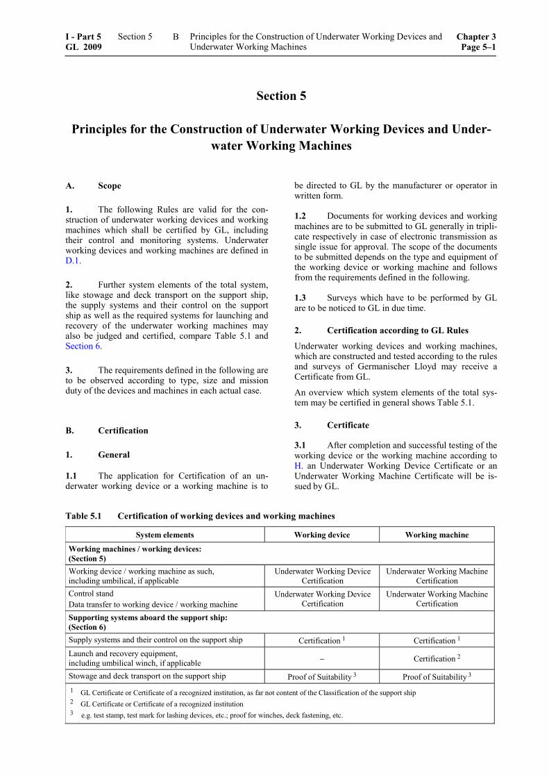
Section 5 Principles for the Construction of Underwater Working Devices and Under-
water Working Machines
A. Scope
1. The following Rules are valid for the con-struction of underwater working devices and working machines which shall be certified by GL, including their control and monitoring systems. Underwater working devices and working machines are defined in D.1.
2. Further system elements of the total system, like stowage and deck transport on the support ship, the supply systems and their control on the support ship as well as the required systems for launching and recovery of the underwater working machines may also be judged and certified, compare Table 5.1 and Section 6.
3. The requirements defined in the following are to be observed according to type, size and mission duty of the devices and machines in each actual case.
B. Certification
1. General
1.1 The application for Certification of an un-derwater working device or a working machine is to
be directed to GL by the manufacturer or operator in written form.
1.2 Documents for working devices and working machines are to be submitted to GL generally in tripli-cate respectively in case of electronic transmission as single issue for approval. The scope of the documents to be submitted depends on the type and equipment of the working device or working machine and follows from the requirements defined in the following.
1.3 Surveys which have to be performed by GL are to be noticed to GL in due time.
2. Certification according to GL Rules
Underwater working devices and working machines, which are constructed and tested according to the rules and surveys of Germanischer Lloyd may receive a Certificate from GL.
An overview which system elements of the total sys-tem may be certified in general shows Table 5.1.
3. Certificate
3.1 After completion and successful testing of the working device or the working machine according to H. an Underwater Working Device Certificate or an Underwater Working Machine Certificate will be is-sued by GL.
Table 5.1 Certification of working devices and working machines
System elements Working device Working machine Working machines / working devices: (Section 5) Working device / working machine as such, including umbilical, if applicable
Underwater Working Device Certification
Underwater Working Machine Certification
Control stand Data transfer to working device / working machine
Underwater Working Device Certification
Underwater Working Machine Certification
Supporting systems aboard the support ship: (Section 6) Supply systems and their control on the support ship Certification 1 Certification 1 Launch and recovery equipment, including umbilical winch, if applicable Certification 2
Stowage and deck transport on the support ship Proof of Suitability 3 Proof of Suitability 3 1 GL Certificate or Certificate of a recognized institution, as far not content of the Classification of the support ship 2 GL Certificate or Certificate of a recognized institution 3 e.g. test stamp, test mark for lashing devices, etc.; proof for winches, deck fastening, etc.
I - Part 5 GL 2009
Section 5 Principles for the Construction of Underwater Working Devices and Underwater Working Machines
Chapter 3Page 5–1
B
3.2 The Certificate certifies the technical condi-tion of the working device resp. the working machine by GL at the time of the tests and approvals. In addi-tion it will be confirmed that no safety reservations are opposing the operation.
3.3 The validity of the Certificate is 5 years at maximum and can be prolonged after renewed tests. For maintaining the Certificate the system is in gen-eral to be subjected to an annual survey. After longer times of standstill a test is to be performed before putting into operation again.
The Certificate looses its validity if substantial changes (influencing the safety of the system) are performed at the device or machine respectively if the system has been severely damaged and the change resp. the repair has not been agreed and approved by GL.
4. Certification according to other rules
4.1 For working devices and working machines, which are not built according to the Rules of GL, the applied rules have to be defined in a binding way in the application for Certification.
4.2 After successful examination a Certificate may be issued by GL.
C. Rules and Regulations to be Considered
1. Rules of GL
1.1 The following Rules are valid as additional requirements for the Certification and construction of underwater working devices and working machines in addition to the Rules for Classification and Construc-tion of GL, e.g.:
– Part 1 – Seagoing Ships, Chapter 2 – 4, as far as applicable
– II – Materials and Welding, Part 1 – 3
– IV – Industrial Services, Part 6 – Offshore Tech-nology, as far as applicable
1.2 For underwater working machines also the plants and systems for control and safe operating have to comply with the relevant Rules of GL.
1.3 Designs differing from the Rules of Construc-tion may be approved provided that they have been recognized by GL as equivalent.
1.4 Underwater working devices and working machines or parts thereof whose development is based on new principles and which have not yet been suffi-ciently tested in practical operation require special approval by GL.
1.5 In the cases mentioned in 1.3 and 1.4, GL is entitled to require the submission of additional docu-mentation and the performance of special tests.
1.6 GL reserve the right to impose demands additional to those contained in the Rules in respect of all types of underwater working devices and working machines when such action is necessitated by new knowledge or practical experience, or to sanction deviations from the Rules in specially justified cases.
2. National regulations
National regulations existing alongside GL's Rules are unaffected.
3. International Conventions and Codes
International Conventions and Codes may also be valid, e.g.:
3.1 MARPOL 73/78
International Convention for the Prevention of Pollu-tion from Ships, 1973 including the 1978 Protocol as amended.
D. Definitions
1. General
Collapse diving pressure CDP
The collapse diving pressure CDP is related to the collapse diving depth CDD of the working device or the working machine, which is decisive for the design and for which a collapse of components can be ex-pected [bar].
Control stand
Desk, console or mobile control unit at which all es-sential indicators, controls, regulating devices and monitoring devices for remote control of the working devices resp. of the working machines are arranged. For the operation of working devices the control stand may be arranged in the manned submersible or on the support ship. For the operation of working machines it is situated in general on the support ship.
Diving pressure
The pressure, corresponding to the relevant diving depth, to which a working device or a working ma-chine is exposed during underwater operations. The diving depth is related to the lower edge of the work-ing machine or for working devices to the baseline of the submersible.
Launching and recovering system
The plant and equipment necessary for launching and recovering working machines.
Chapter 3 Page 5–2
Section 5 Principles for the Construction of Underwater Working Devices and Underwater Working Machines
I - Part 5GL 2009
D
Lifting cable
Cable for launching and recovering, and also for lift-ing and lowering of a working machine.
Nominal diving pressure NDP
The nominal diving pressure is related to the diving depth NDD for the unrestricted operation of the work-ing device or working machine [bar].
Payload NL of the working machine
Maximum additional load which the working machine is able to carry for the jobs to be performed, e.g. in-vestigation of the sea and scientific research.
Gas cylinders
Bottles for the storage and transport of gases under pressure
Pressure vessels
Container capable of withstanding an internal or ex-ternal maximum allowable working pressure of 1 bar or above.
Support ship
A surface vessel for support and supply of working machines. Within these Rules the support ship may also be a stationary supply station (e.g. on the coast or on a stationary offshore plant).
Test diving pressure TDP
The test diving pressure TDP is related to the test diving depth TDD which is adequate to an external overpressure to which the working device or the work-ing machine is subjected after completion or after essential repairs and conversions under testing condi-tions [bar].
Total system
Underwater working machine or submersible with working device or including its control, launching, recovery, stowing, transport and supply systems.
Umbilical
Connection between support ship and working ma-chine, which might contain control, monitoring, data transfer and power supply lines as well as the lifting cable.
Working device (underwater)
Device, e.g. manipulator or tool, which is fixed to a submersible resp. to an underwater working machine and which is designated to the performance of under-water tasks.
Working machine (underwater)
Machines, e.g. grab, driver, drill and their combina-tion, which are normally used from a support ship to perform underwater tasks.
2. Types of underwater working devices
Underwater working devices are e.g.:
2.1 Video cameras
Cameras can be mounted on either a pan and tilt as-sembly, held by a manipulator arm or may be arranged in a fixed position. With movable cameras pictures of areas which are not easy to be looked at or under spe-cial visual angle can be made. To improve visibility search lights are to be provided.
2.2 Devices for non-destructive material test-ing
These devices serve to verify the intactness of off-shore structures and include thickness measurement devices, flooded member detectors and current density devices, etc.
2.3 Devices for acoustic measurements and position determination
These devices include measuring systems and systems for determination of position and all types of ac-tive/passive sonar systems, like sonar or echo sound-ers to detect hindrances, sea bottom survey, tracking of pipelines, etc.
2.4 Cleaning devices
These devices serve to clean ships or offshore struc-tures with e.g. rotating wire or nylon brushes and water-jetting systems with or without abrasives.
2.5 Fixing systems
These systems are serving for temporary fixing of a submersible with working devices resp. of a working machine e.g. on an underwater structure. Fixing sys-tems may be mechanical or hydraulic systems.
2.6 Search lights
Search lights including their pressure-proof housing with penetrations, which are applied for illumination of an underwater range, are considered as working de-vice in the sense of these rules
2.7 Manipulators
Manipulators are used for fixing, for handling tools and for the execution of working missions.
2.8 Further working devices
Further working devices may be devices for taking samplings, transport containers, special measuring devices or devices for special tasks.
3. Types of working machines
Working machines with the capability to perform e.g. the following activities under water:
I - Part 5 GL 2009
Section 5 Principles for the Construction of Underwater Working Devices and Underwater Working Machines
Chapter 3Page 5–3
D
– welding
– cutting/separating
– drilling
– doweling, anchoring
– pumping
– milling
– excavating/filling up
– flushing
– ramming/vibrating
– installing
– mounting
– connect/disconnect
– geological mining
– mission related special tasks
E. Environmental Conditions
1. General
For the design of working devices and working ma-chines environmental conditions defined in the follow-ing are to be considered. For working devices and working machines which are used only in certain areas, different environmental conditions may be approved.
2. Inclined positions
As far as not specified otherwise, satisfactory opera-tion shall be ensured at (static and dynamic) inclina-tions of up to 22,5° in any direction measured in rela-tion to the as-installed datum. Transient inclinations of up to 45° shall not adversely affect operation and shall not cause damage, particularly to machine mountings. For greater operational inclinations these have to be considered adequately for design and testing.
3. Water
For the design of working devices and working ma-chines the temperature range of the water as well as the range of salt content and therefore of the density is to be defined. If not agreed otherwise, seawater with a temperature range from –2 °C to +32 °C, with a salt content of 3,5 % and a density of 1028 kg/m3 may be used as a basis. A value of 0,101 bar/m is to be ap-plied when converting diving depth to pressure.
4. Seaways
The seaways up to which the mission is to be per-formed, are to be agreed with GL. If not agreed oth-erwise, it is to be designed for sea states with a sig-nificant wave height of at least 2 m. Allowance is being made for accelerations of 2 g downwards and 1 g upwards in the vertical and 1 g each in the longitu-dinal and transverse directions (g = 9,81 m/s2).
5. Tide and currents
Current conditions are to be considered for the design according to the operation area.
As basis for the design the maximum as well as the minimum tide at the relevant operation area shall be included. In addition currents created by storms or geographic specialities (e.g. narrow channels) are to be considered, as far as necessary.
6. Climate
For transport, storage, maintenance, inspection and trials out of water of working devices and working machines on board of the support ship as well as for the launch and recovery system of the working ma-chine salt impregnated air ranging in temperature from –10 °C to +55 °C at a relative atmospheric humidity of 100 % has to be assumed.
In the protected control rooms for working machines installed on board of the support ship, a relative at-mospheric humidity of 80 % at a reference tempera-ture of 45 °C is to be assumed.
7. Vibrations and shaking
Working devices and working machines shall not cause any vibration or shaking which imposes unac-ceptable stresses on other machines, equipment or the hull of the submersible. The amplitudes and accelera-tions defined in the GL Rules for Machinery Installa-tions (I-1-2), Section 1, C. are to be complied with.
8. Explosion protection
Working devices and working machines which are used in respectively from explosion endangered areas (e.g. platforms for extraction of oil and gas) are to be designed for the relevant explosion zones. This is also valid for control stands.
9. Further environmental conditions
For the design of working devices and working ma-chines eventual the environmental conditions occur-ring during an air transport (e.g. underpressure / tem-perature) are to be considered.
F. Principles for Design and Construction
1. Working devices
1.1 Total system
Working devices are to be coordinated with the sub-mersible in relation to size and effect and shall not lead to any impairment of the function of the submersible.
The working device shall meet at least the applicable design parameters for the manned or unmanned sub-mersible.
Chapter 3 Page 5–4
Section 5 Principles for the Construction of Underwater Working Devices and Underwater Working Machines
I - Part 5GL 2009
F
1.2 Power supply
For greater power demand the power supply for the working device shall be separated from the supply of the submersible itself.
Fixing system shall be designed according to the fail safe principle, i.e. in case of power failure the fixing device opens, if this creates no additional danger.
If the mission requires an emergency operation be-cause of failure of the main power supply, e.g. to finish already started works, this is adequately to be considered.
1.3 Tools
Tools which can be changed by remote control, are to be provided with measures to avoid the leakage of operation media or the ingress of sea water in the supply system.
Tilting and slewing tools are to be designed in a way that existing power, supply or control connections will not be twisted off or damaged.
2. Working machines
2.1 Layout
2.1.1 Working machines are to be designed for all planned operation conditions. As a basis the require-ments defined in Section 3 are to be considered as far as applicable.
2.1.2 Components of working machines which are subjected to external pressure are to be designed at least for 1,0 × collapse diving pressure CDP.
2.1.3 For the layout the safety factors CDP/NDP and TDP/NDP according to Section 3, Table 3.1 are to be applied.
2.1.4 The lifting points at the working machine shall have a safety against rupture of 8 times the safe working load SWL and are to be clearly signed and marked with their safe working load SWL.
2.1.5 For the safety of working machines it may be required (e.g. according to a Failure Modes and Ef-fects Analysis – FMEA, compare Section 2, F.) to pro-vide redundant systems or components.
2.1.6 In addition it can be required, that e.g. open and closed loop control, monitoring devices or tools are redundantly designed to increase the availability of working machines, especially for deep sea missions.
2.2 Power supply
In the case of a main power supply failure or interrup-tion of the remote control the working machine has to reach a defined and safe operating condition.
2.3 Control and monitoring
For this especially is to be observed:
– Systems are to be provided that are able to monitor the position of the working machine at the working location at any time. These may not be part of the working machine.
– The actual status of the working machine and the working function in execution has to be in-dicated at the control stand on the support ship.
– The operating parameters required for the safe operation of the working machine are to be indi-cated at the control stand and are to be provided with acoustic and/or optical alarms according to the priorities.
– For immediate finishing of the works in case of emergency an emergency stop device is to be provided. In case the execution of several work-ing functions is arranged automatically one after the other, manual interruption of this sequence has to be possible at any time.
– If visual monitoring is required for underwater missions, measures are to be provided which en-able an adequate illumination of the working area and the use of video cameras.
– To protect the working machine and also sensi-ble objects to be treated from damages, overload protections are to be provided for the different working functions.
– If a twisting of the machine shall be hindered during the mission, an anti-twist unit is to be provided.
2.4 Emergency surfacing system
If required an emergency surfacing system with defined actuation is to be provided to avoid e.g. a total loss of the working machine if the lifting cable is destroyed.
2.5 Missions with divers
If a joint mission with divers is planned, suitable safety measures, like e.g. protection grids for shielding of dangerous areas or similar are to be provided. In addition an easily visible and easily accessible emer-gency stop device at a suitable location (at the work-ing machine, at the 2nd diver) has to be available. Fur-ther the electrical installations according to Section 3, L.4. are to be protected for a mission with persons.
2.6 Missions at the sea bottom
Working machines for missions on the sea bottom are to be designed that a minimum possible influence on the sea bottom and its flora and fauna is guaranteed.
2.7 Further requirements
Further requirements are - as far as applicable - to be accomplished in analogous form to the unmanned submersibles respectively are to be agreed with GL case by case.
I - Part 5 GL 2009
Section 5 Principles for the Construction of Underwater Working Devices and Underwater Working Machines
Chapter 3Page 5–5
F
G. Documents for Approval
1. General
The general requirements defined in Section 2, E.1. are also valid here.
2. Total system
The following documents are to be submitted:
2.1 Description of the working device and its interface to the submersible resp. of the working ma-chine with data about type of operation, planned mis-sion duty and the essential layout parameters, like e.g.:
– nominal diving depth NDD
– limits of mission in relation to launch and re-covery (seaway)
– other limits of mission in relation to environ-mental conditions, e.g. salt water/fresh water or similar
– type and extent of working devices resp. of the working machine
– for working devices: arrangement and fixing at the supporting structure
– materials used
– maximum power demand and power supply
– type and quantity of the used operational media
– control and monitoring
– safety systems
– if existing, type of emergency emerging system
– weight of working device resp. of working ma-chine, payload and ballast volume
2.2 General arrangement drawing of the working device resp. of the working machine.
2.3 Schematic drawings (block diagrams) of the total system, in addition details about systems pro-vided for supply and support of the working device resp. of the working machine (e.g. control stand, launching and recovery system, umbilical for power supply, etc.).
2.4 A comprehensive presentation of the meas-ures taken to prevent corrosion especially for func-tionally essential components.
2.5 Stability documentation (according to mis-sion duty and construction) for the submersible with working device resp. for the working machine, if ap-plicable.
2.6 Manual for operation and maintenance
The manual for the operation shall include in detail the steps necessary for normal operation as well as for emergency operation in a clear and conceptual form and in the necessary sequence (e.g. as checklists). In addition the measures for the charging of the operating systems (e.g. batteries, gas/fuel containers) are to be defined. In addition the planned lifetime as well as the permissible load and operation cycles of parts of the equipment (e.g. acrylic windows, batteries) is to be defined herein.
The maintenance manual shall include all procedures for the preventive maintenance as well as for periodic inspections.
2.7 Operational records
All conditions relevant for the mission (diving depth, mission time, damages, etc.) are to be documented .
2.8 Trial program.
2.9 Documents required further are to be taken from Section 2, E.
H. Tests and Trials
1. Constructional and acceptance test
1.1 General
1.1.1 Remotely operated working devices and working machines are subject to constructional and acceptance testing at the manufacturer's workshop as far as possible. In addition, all the tests and trials pre-scribed in the following are to be performed and documented, wherever applicable. About the presence of GL Surveyors at these tests and trials GL will de-cide case by case.
1.1.2 For series-manufactured parts, test proce-dures other than those prescribed may be agreed with GL provided that they are recognized as equivalent by GL.
1.2 Total system
On completion, the working device including the envisaged submersible resp. the working machine with the necessary ancillary equipment, like e.g. control stand, energy supply, etc., is to be subjected to a func-tional and acceptance test. In general the following individual tests are to be performed:
– inspection of assembly (where not already per-formed during supervision of manufacture)
– measurement of weight and buoyancy, eventu-ally stability
Chapter 3 Page 5–6
Section 5 Principles for the Construction of Underwater Working Devices and Underwater Working Machines
I - Part 5GL 2009
H

– static test of the lifting points at the working machine with 2,2 times the safe working load SWL (weight + payload NL of the working ma-chine)
– static test of the connecting points for the um-bilical at the working machine with 2,2 times the maximum permissible tensioning load of the umbilical
– check of control and monitoring
– check of all safety systems
– check of redundant systems and components
– functional testing of mechanical, electrical and optical equipment including fixing systems and working devices
– check of all essential measuring instruments
– high voltage test and insulation test on the elec-trical equipment before and after the trials under water
– check of arrangements to avoid dangers for the divers
– check of eventual affects on the submersible by working devices including functional test and change of working device, if applicable
– pressure testing of the working machine resp. of its components subjected to external pressure (vessels, apparatus, electrical penetrations, etc.) or of the working device with test diving pres-sure TDP
– trials and functional tests under water without the specified performance proof for the working function for diving depth up to nominal diving depth NDD
Before the trials at nominal diving depth NDD nor-mally functional tests are to be performed on land and in shallow water.
Further required tests are defined according to the equipment in Section 2, F.
1.3 Check of working functions
The proof for the specified performance parameters of working devices and working machines may be per-formed with simulated working conditions, e.g. in a pressure tank, or by a deep water trial with nominal diving depth NDD. The scope of the proof of per-formance has to consider the parameters specified for nominal diving depth NDD and is to be agreed with GL.
Only after the successful proof of performance, the relevant performance data of the underwater working device resp. of the working machine can be included into the Certificate.
2. Repeated tests
Check of documents for the working machine resp. the working device and inspection of the operational re-cords.
The complete system is to be checked for visible dam-ages, cracks, deformations and corrosion attacks.
The complete system is to be subjected to a functional test.
Further tests specific to the machine are defined by GL case by case.
I. Marking
1. All working devices and working machines are to be provided with permanent and seawater resis-tant markings.
2. The marking shall contain:
– name or company designation of manufacturer
– year of construction
– serial number
– nominal diving pressure NDP [bar]
– maximum allowable working pressure [bar] of the systems under pressure
– performance parameters according to type of work-ing device respectively of working machine
– if necessary, further characteristic parameters according to type of device /machine
– electrical data (voltage, amperage, etc.)
– weight [kg]
– if necessary, permissible payload NL [kg] and belonging load radius [m]
– date of test
– test stamp
J. Spare Parts
1. In order to restore operation capability of the working device or the working machine in the event of damage at sea, spare parts for the essential equipment shall be available together with the necessary tools on board of the support ship resp. in the surrounding area to the mission location.
2. The scope of spare parts is to be documented and a relevant listing has to be on board of the support ship.
3. For change or repair of essential or safety relevant components B.3.3 is to be observed.
I - Part 5 GL 2009
Section 5 Principles for the Construction of Underwater Working Devices and Underwater Working Machines
Chapter 3Page 5–7
J
K. Operational Media
1. Operational media such as hydraulic fluids, lubricants, etc. are to be selected in accordance with the proposed ambient conditions. They shall not tend to congeal or evaporate over the whole temperature range.
2. Operational media are to be so selected that water penetration resp. mixing with seawater does not essentially impair the functionality of the submersible.
3. Operational media shall not contain toxic ingredients which are liable to be hazardous to health through skin contact or when given off in fumes.
4. Operational media should not be corrosive or attack other operating equipment (e.g. seals, hose assemblies, etc.).
L. Corrosion Protection
Underwater working devices and underwater working machines and all adjacent components are to be pro-tected effectively against corrosion. Further in-formation can be gained from the GL Guidelines for Corrosion Protection and Coating Systems (VI-10-2).
Chapter 3 Page 5–8
Section 5 Principles for the Construction of Underwater Working Devices and Underwater Working Machines
I - Part 5GL 2009
L
Section 6
Supporting Systems aboard the Support Ship
A. General
1. Scope
The following Rules are valid for plants and systems which are located aboard the support ship for sub-mersibles and which are necessary for the support of the operation according to type and purpose of the mission of the submersible respectively of the under-water working machine.
2. Definitions
For the definitions see Section 2, C. (ROV, AUV) and Section 5, D. (working devices and working ma-chines).
3. Rules to be considered
For the Rules to be considered see Section 2, B. (ROV, AUV) and Section 5, C. (working devices and working machines)
4. Environmental conditions
The environmental conditions according to Section 2, D. (ROV, AUV) and Section 5, E. (working devices and working machines) are to be applied analogously for the supporting systems on the support ship.
5. Communication systems
As far as several areas not situated nearby are required aboard of the support ship for the safe operation of the submersible resp. working machine, these are to be connected to each other by a suitable communication system.
B. Classification and Certification
1. To guarantee an undisturbed and safe opera-tion of the submersible resp. of a working machine, the supporting systems are to be either classified or certified (see Section 1, Table 1.1 and Section 5, Table 5.1).
2. For the Classification of a submersible with Class Notation ROV or AUV the systems according to C.2. and C.3. are belonging to the submersible. The procedure to be applied is defined in Section 1, C.
3. For the ROV- or AUV-Certification of a sub-mersible the systems according to C.2. and C.3. are belonging to the submersible. The procedure to be applied is defined in Section 1, B.
4. For the Certification of further systems by GL a Certificate will be issued. The procedure to be applied is defined in Section 5, B.
C. Systems for Control
1. General
1.1 As systems for control the control station, the data transfer systems to the submersible resp. to the working machine and the dynamic positioning system of the support ship are summarized.
1.2 The proof of the suitability of control station and data transfer has to be given by GL Classification or an ROV-Certificate (compare Section 1, Table 1.1) resp. an Underwater Working Machine Certificate for the working machine (compare Section 5, Table 5.1) of GL. In both cases the following requirements are to be considered.
1.3 If systems for control/data transfer are used for AUVs, 1.2 has to be applied analogously.
2. Control station
2.1 As far as applicable, the requirements defined in Section 3, M.2. are valid for a control station aboard the supply ship in analogous way.
2.2 The following requirements are to be consid-ered additionally:
– The power demand defined by the manufacturer of the submersible resp. working machine has to be made available.
– The power supply of the control station for re-motely controlled submersibles/working ma-chines shall be established by two power circuits independent from each other which can be switched over. Alternatively a direct feeding from the emergency switchboard of the support ship may be provided.
I - Part 5 GL 2009
Section 6 Supporting Systems aboard the Support Ship Chapter 3Page 6–1
C
– The permissible deviations of voltage and fre-quency according to GL Rules for Electrical In-stallations (I-1-3), Section 1 shall not be ex-ceeded.
– For the power supply of control, monitoring and safety systems the requirements according to the GL Rules for Electrical Installations (I-1-3), Section 9 are to be met.
– The minimum degrees of protection for the control station are to be provided according to the GL Rules for Electrical Installations (I-1-3), Section 1.
– An emergency stopping device for the sub-mersible resp. the working machine is to be in-stalled at the control station. This is to be pro-vided in a way that unintentional actuation is excluded.
– If the control station is not located directly at the bridge, a communication system between them is to be provided.
– Between the control station and the control stand for the supply systems according to D. a communication system is to be established.
– In the vicinity of the control station no systems or plants are to be installed which impair the monitoring and control of the submersible resp. of the working machine.
2.3 2.1 and 2.2 are only to be applied to the con-trol station of an AUV, if the control station is re-quired for the save operation of the AUV.
2.4 Plans and descriptions of the control station and its power supply are to be submitted for the areas relevant here.
3. Data transfer systems
3.1 As far as applicable, the requirements for data transfer systems defined in Section 3, M.4. are valid on board of the support ship in the same way.
3.2 The energy supply for the data transfer to the submersible resp. to the working machine is to be provided in analogous way to 2.2.
3.3 3.2 is only to be applied to the data transfer system of an AUV, if the data transfer is required for the save operation of the AUV.
3.4 Plans and descriptions of the data transfer systems of the support ship are to be submitted for the relevant areas.
4. Dynamic positioning of the support ship
4.1 A ship with dynamic positioning is a vessel which automatically keeps its position (fixed location or pre-determined track) exclusively with the aid of propeller/jet drives.
Especially for remotely controlled submersibles (ROV) and working machines it may become neces-sary to provide a dynamic positioning of the support ship as the ROV resp. the working machine is con-nected to the support ship via an umbilical and/or lifting cable.
4.2 As far as applicable, the requirements for positioning systems defined in Section 3, J. are valid for the support ship in analogous way.
4.3 All requirements for Classification of a posi-tioning system are included in the GL Rules for Dynamic Positioning Systems (I-1-15). According to the degree of redundancy GL may assign the Class Notations DP1, DP2 and DP3.
The support ship has also to meet the regulations of IMO: "Guidelines for Vessels with Dynamic Position-ing Systems" (MSC/Circ. 645).
4.4 Documents to be submitted
The following documents are to be submitted:
– description of the main characteristics of the system
– block schematic diagrams of the control system and applied logics
– information about possibilities for the position balance between the involved units
5. Tests and trials
5.1 Within the Classification together with the submersible an acceptance test after completion, an annual survey, an intermediate survey and a class renewal survey after 5 years is to be performed.
5.2 If control station and data transfer systems are to be surveyed for issuance of a ROV-/AUV Cer-tificate resp. an Underwater Working Machine Certifi-cate, an acceptance test after manufacturing and nor-mally an annual survey is required.
5.3 Within the acceptance test the compliance of the documentation with the system as well as the safe functioning during normal and emergency operation has to be proven.
5.4 Within the repeated surveys the complete system is to be checked for visual damages and corro-sion and is to be subjected to a functional test for normal and emergency operation.
Chapter 3 Page 6–2
Section 6 Supporting Systems aboard the Support Ship I - Part 5GL 2009
C
D. Supply Systems
1. General
1.1 Systems of the support ship, which provide energy in form of electrical power, hydraulic oil and compressed air at the interface to the umbilical are supply systems. For remotely operated submersibles (ROV) and working machines normally the supply is necessary during the preparation of the mission as well as continuously during the mission, for autono-mous submersibles (AUV) between the missions.
1.2 The proof of the suitability of these systems can be provided by a Class Certificate of the supply ship or by a separate Certificate of a recognized insti-tution (compare Section 1, Table 1.1). If no Certificate is existing and the establishment of such a proof is ordered from GL by the manufacturer or operator, the following requirements are to be considered.
2. Electrical supply
2.1 As far as applicable, the requirements defined in Section 3, L. are valid for the support ship in analo-gous form as well as state-of the-art-technology.
2.2 The following requirements are to be consid-ered additionally:
– The power demand defined by the manufacturer of the submersible resp. working machine has to be made available at any time. The additional demand for eventual working devices (compare Section 5) is to be considered.
– If a dangerous condition for the consumer may arrive if the main supply fails, special measures are to be provided in accordance with GL.
– The emergency power supply on the support ship shall be able to provide the power demand until a safe condition of the underwater mission is reached.
– The permissible deviations of voltage and fre-quency according to GL Rules for Electrical In-stallations (I-1-3), Section 1 shall not be ex-ceeded.
2.3 Plans and descriptions of the electrical power supply system of the support ship are to be submitted within the GL Certification for the areas relevant here.
3. Hydraulic supply
3.1 As far as applicable, the requirements defined in GL Rules for Machinery Installations (I-1-2), Sec-tion 14 are valid for the support ship as well as state-of-the-art-technology.
3.2 The following requirements are to be consid-ered additionally:
– The demand of hydraulic oil (volume, pressure range) defined by the manufacturer of the sub-mersible resp. the working machine has to be made available at any time. The additional de-mand for eventual working devices (compare Section 5) is to be considered.
– If a dangerous condition for the consumer may arrive if the main supply fails, special measures are to be provided and to be agreed with GL.
– If necessary, the emergency supply at missions of submersibles/working machines shall be able to provide the defined oil demand until a safe condition of the underwater mission is reached.
– The permissible deviations of volume and pres-sure are to be in accordance with the data of the manufacturer of the ROV/working machine and shall not be exceeded resp. shall not fall short of.
– The hydraulic fluid is to be suitable for the op-erational conditions and especially for the envi-ronmental conditions above and under water (see Section 2, D.).
3.3 Plans and descriptions of the hydraulic sys-tem of the support ship are to be submitted within the GL Certification for the areas relevant here.
4. Supply of compressed air
4.1 For the calculation, choice of materials and manufacturing of the compressed air system on the support ship the GL Rules for Machinery Installations (I-1-2), Section 11 as well as state-of-the-art-techno-logy are to be recognized.
4.2 The following requirements are to be consid-ered additionally:
– The demand of compressed air (volume, pres-sure range) defined by the manufacturer of the submersible resp. the working machine has to be made available at any time. The additional de-mand for eventual working devices (compare Section 5) is to be considered.
– If a dangerous condition for the consumer may arrive if the main supply fails, special measures are to be provided in accordance with GL.
– If necessary, the emergency supply at missions of ROVs/working machines shall be able to pro-vide the defined demand of compressed air until a safe condition of the underwater mission is reached.
– The permissible deviations of volume and pres-sure are to be in accordance with the data of the manufacturer of the ROV/working machine and shall not be exceeded resp. shall not fall short of.
I - Part 5 GL 2009
Section 6 Supporting Systems aboard the Support Ship Chapter 3Page 6–3
D
– Between the supply system for underwater mis-sions and the compressed air system for the op-eration of the support ship a safe separation is to be provided.
4.3 Plans and descriptions of the compressed air system of the support ship are to be submitted within the GL Certification for the areas relevant here.
5. Tests and trials
5.1 For the issue of a Certificate for the different supply systems an acceptance test after manufacturing and for maintaining of the Certificate normally an annual survey is to be performed.
5.2 Within the acceptance test the compliance of the documentation with the system as well as the safe functioning during normal and emergency operation has to be proven.
5.3 Within the repeated surveys the complete system is to be checked for visual damages, cracks, deformations and corrosion and is to be subjected to a functional test for normal and emergency operation.
E. Launch and Recovery System
1. General
1.1 The following requirements are valid for all systems and plants for launch and recovery as well as for coil-up/coil-off mechanism for umbilicals of un-manned submersibles resp. of working machines to be certified by GL, compare Section 1, Table 1.1 resp. Section 5, Table 5.1.
1.2 The proof of the suitability of these systems is to be provided by a separate Certificate of a recog-nized institution (compare Section 1, Table 1.1). If no Certificate is existing and GL is appointed with the issue of such a proof by the manufacturer or operator, the following requirements are to be recognized.
1.3 If the systems are constructed and tested under GL surveillance considering the following re-quirements, a Certificate for the system can be issued and a Register of launching appliances can be opened. The latter has the purpose to provide information about the actual situation with regard to general data plus the test, examination and maintenance status.
Details are defined in the GL Guidelines for the Con-struction and Survey of Lifting Appliances (VI-2-2).
1.4 Besides of the launch and recovery system an emergency recovery system is to be provided that al-lows the submersible resp. the working machine to be lifted to the surface in an emergency. Other measures
may be provided in accordance with GL. An adequate emergency recovery plan is to be submitted.
1.5 Between the launch and recovery system and the umbilical winch, if separately arranged, a commu-nication facility with the control station of the sub-mersible resp. the working machine and the bridge of the support ship is to be established.
2. Principles for design, computation and equipment
2.1 Design
2.1.1 Design loads
2.1.1.1 The "safe working load SWL" of the launch and recovery system summarizes as follows:
– weight of the submersible, including its equip-ment, ballast weights, etc.
– payload NL of the submersible
– total weight of the lifting cable
– weight of the load transmitting devices which are not connected in a fixed way with the launch and recovery system
– resulting loads of the umbilical according to 3. if this is transferred via the launch and recovery system
For the launch and recovery systems of working ma-chines the safe working load SWL is to be evaluated in analogous form.
2.1.1.2 Calculations are to be based on the assump-tion that the angle of engagement of the lifting cable may be 12° off perpendicular in any direction.
2.1.1.3 For the calculation also further possible ex-ternal loads, which may occur during operation (e.g. dynamics, wind loads, ice accretion, etc.) are to be considered. A proof of strength is to be submitted under consideration of the seaway and wind condi-tions according to Section 2, D.
2.1.1.4 Finally also the forces from maximum ship motions and green seas, wind, ice, etc. have to be checked for the launch and recovery system in resting position and stowed on the supply ship.
2.1.1.5 In addition the minimum heaving speed is to be specified by the manufacturer and to be agreed with GL.
2.1.1.6 The driving machine of the winch has to be designed in a way, that a maximum torque according to a maximum pull of 1,5 times the nominal pull of the winch can be developed at reduced speed for at least 5 minutes. In analogy the hydraulic cylinders are to be laid out for 1,5 times the nominal cylinder force. For both a calculation proof is to be provided.
Chapter 3 Page 6–4
Section 6 Supporting Systems aboard the Support Ship I - Part 5GL 2009
E
2.1.1.7 The launch and recovery system shall be capable to safely launch and recover the submersible resp. the working machine at the seaway conditions defined in Section 2, D.
2.1.2 Power supply, mechanical drives
2.1.2.1 The launch and recovery system shall have an energy source which is able to deliver the full energy demand required for the launch and recovery of the submersible.
2.1.2.2 The launch and recovery system is to be equipped with auxiliary drives enabling a launch or recovery manoeuvre which has already been started to be safely concluded should the winches or hydraulic pumps fail.
2.1.2.3 Launch and recovery systems using an "A" frame are to be equipped with two hydraulic cylinders which are to be so designed and arranged that each is fully capable of safely performing the launch and recovery operation under load. In addition, they are to be connected to the hydraulic system in such a way that a single fault in the hydraulic system cannot lead to the failure of both hydraulic cylinders.
2.1.3 Control equipment
2.1.3.1 Launch and recovery systems are to be fitted with control equipment enabling the system to be operated intermittently with smooth accelerations. In addition, the controls are to be designed and arranged in such a way that the operator has the submersible resp. the working machine in his visual field through-out complete launch and recovery and is fully able to perform all the necessary actions.
2.1.3.2 The controls are to be fitted with blocking devices which ensure that only those commands can be performed simultaneously which do not produce a dangerous or unintended condition.
2.1.3.3 Control systems are to be provided with emergency shut-off buttons.
2.1.3.4 Wherever possible, control units are to oper-ate on the fail-safe principle.
2.1.3.5 Control units with remote control are to be additionally equipped with a direct control override. In the event of failure or malfunction of the remote con-trol, all operating sequences which have been initiated shall be automatically stopped.
2.1.3.6 All control units are to be clearly and perma-nently marked and shall be adequately illuminated.
2.2 Materials
2.2.1 For the manufacture, processing and testing of materials the GL Rules II – Materials and Welding, Part 1 – Metallic Materials and Part 2 – Non-metallic Materials are valid.
2.2.2 Other materials as defined in 2.2.1 are to be manufactured and processed according to recognized standards resp. according to specifications of the ma-terial manufacturer checked and approved by GL.
2.3 Calculation
2.3.1 The calculation of the launch and recovery system as well as of the coil-up/coil-off mechanism for umbilicals is to be performed according to the principles of GL Guidelines for the Construction and Survey of Lifting Appliances (VI-2-2). For this com-putation the system is to be considered as offshore lifting gear.
If the system is equipped with shock absorbers or swell compensators approved by GL, a reduction of the working load may be dispensed with totally or partially if agreed by GL.
2.3.2 Deviating from the design of offshore lifting gears, for the dimensioning of launch and recovery systems a hoist load coefficient of 2,7 and a dead load coefficient of 1,5 are to be considered independently of type and size of their safe working load. In this con-nection it is assumed that an employment in a seaway is restricted to significant wave heights up to 2 m.
Where it is proposed that launch or recovery opera-tions should be performed in even more unfavourable conditions, previous agreement with GL is necessary.
2.4 Equipment
2.4.1 Where cranes are used for launch and recov-ery, measures are to be taken to prevent the uncon-trolled turning or slewing of the crane in a seaway. The turning or slewing gear has to be capable of hold-ing the crane in any position. The gear is also to be designed to ensure that all movements are started and braked smoothly.
2.4.2 Launch and recovery systems are to be equipped with measures which prevent excessive turning or swinging of the submersible resp. the work-ing machine during recovery (e.g. by the use of non-spin ropes and additional pendants).
2.4.3 Measures are to be provided to prevent the submersible resp. the working machine from striking against the ship's hull or against the launch and recov-ery gear.
2.4.4 Winches are to be equipped with two inde-pendent brakes. One of the brakes is to be energy independent and shall be activated in case of voltage failure.
2.4.5 The capacity of the brakes has to be sufficient to safely hold the dynamic test loads specified in 5.1.
2.4.6 The final positions of the launch and recovery system, like upper and lower hook and jib position as
I - Part 5 GL 2009
Section 6 Supporting Systems aboard the Support Ship Chapter 3Page 6–5
E
well as the slewing range, are to be monitored. The starting and breaking velocities are to be controlled.
2.4.7 In the case the submersible resp. the working machine is not hanging on the lifting cable, a coupling system is to be provided to enable the submersible to be safely and efficiently coupled to and uncoupled from the launch and recovery system.
2.4.8 All interchangeable single components such as blocks, hooks, shackles, etc. are to conform to rec-ognized standards, shall have a safety of 8 against fracture related to the safe working load SWL and are to be marked with their safe working load.
2.4.9 The maximum static tensile stress imposed on steel wire ropes by the safe working load may not exceed 1/8 of the proven breaking load.
2.4.10 The use of ropes made of fibres is only per-missible with special consent of GL. For the use of natural or synthetic fibres the maximum static tensile stress imposed by the safe working load may not ex-ceed 1/10 of the proven breaking load.
3. Coil-up/coil-off mechanism for umbilicals
3.1 Coil-up and coil-off mechanism for umbili-cals describe the complete equipment for handling of the umbilical on the support ship. They may be of different types, but often an umbilical winch is an integrated part of this system.
3.2 An adequate coil-up and coil-off mechanism is to be provided for the umbilical, which is tracking the umbilical without restriction of the freedom to move and without additional mechanical loads to the element under water.
If a control system for following up umbilicals (TMS - Tether Management System) is provided for the mechanism, the requirements of Annex E, B.2.2 are to be considered.
3.3 The following requirements are to be consid-ered for the design of coil-up and coil-off mechanism for umbilicals:
– specified operating conditions, e.g. wave height and type of support ship
– safe working load SWL of the coil-up and coil-off mechanism for umbilicals considering the weight of the umbilical, its buoyancy in water (filled and empty) as well as the friction in water and dynamic effects, e.g. by the seaway
– The radius of the umbilical in the coil-up and coil-off mechanism is not to be less than the specified bending radius of the umbilical.
– most unfavourable arrangement of the umbilical in relation to the coil-up and coil-off mechanism (e.g. coil-up angle, position of the winch drum, application of guide pulleys, etc.)
– The material Certificates have to be in accor-dance to the GL Guidelines for the Construction and Survey of Lifting Appliances (VI-2-2).
– The coil-up and coil-off mechanism have to have a power source which has the ability to safely coil-up and coil-off the umbilical under the specified conditions.
– The coil-up and coil-off mechanism is to be equipped with auxiliary drives to be able to fin-ish an already started coil-up and coil-off proce-dure in a safe way if the main drive respectively the hydraulic pump are failing.
– To avoid overstressing of umbilical and the coil-up and coil-off mechanism measuring of the tension force is to be provided at a suitable posi-tion of the system, which triggers an alarm at the control stand in case of exceeding the safe working load SWL.
4. Documents for approval
Within the GL Certification the following documents are to be submitted:
4.1 Description of the system with definition of the mission conditions and technical data including recovery and launching speed.
4.2 Data about installation and connection condi-tions including control stand.
4.3 Design drawings of:
– launch and recovery systems
– coil-up and coil-off mechanism for umbilicals
– substructure for gears and winches
4.4 Detailed drawings of exchangeable single parts and fittings or definition of the standards where they are based on.
4.5 Drawings of the machinery equipment like e.g. winches, drives, etc.
4.6 Connection diagram of the hydraulic and pneumatic systems.
4.7 Control scheme and description of the safety systems.
4.8 Information about nominal data and type of protection of the electrical installation
4.9 Data for lifting cables/umbilicals.
Chapter 3 Page 6–6
Section 6 Supporting Systems aboard the Support Ship I - Part 5GL 2009
E
5. Tests and trials
5.1 Acceptance test Before putting into operation of the launch and recov-ery system as well as the coil-up/coil-off mechanism for umbilicals an acceptance test with the following single tests is to be performed: – check that proofs are available for all exchange-
able single parts – The breaking load of the used ropes is to be
proven by a total rupture test and to be certified. – static test of the system at the manufacturer with
a test load equal to 2,2 times the safe working load SWL
– dynamic test (brake test) aboard with 1,25 times the safe working load SWL
– For an A-frame operated by two hydraulic cyl-inders an additional test with SWL and use of only one cylinder is to be performed.
– check of the minimum heaving speed – test that the procedure of launch and recovery of
the submersible/the working machine respec-tively the coil-up and coil-off of the umbilical is performed in normal and emergency operation safely and without jerk
– check of lifting cable coupling system, if appli-cable
– test of function including safety and alarm sys-tems.
5.2 Repeated tests
For maintaining the Certificate the launching and re-covery system is to be subjected to an annual survey.
For this the complete system including all lifting tack-les is to be checked for visible damages, cracks, de-formations and corrosion and is to be subjected to a functional test including a brake test (power failure).
Every 5 years a dynamic test with 1,25 times SWL in-cluding a brake test (power failure) is to be performed.
6. Marking
The launch and recovery systems as well as the coil-up/coil-off mechanism for umbilicals are to be marked with a fixed type plate at a good visible position which contains in easily readable writing the following data:
– manufacturer
– serial number and year of construction
– safe working load SWL [t]
– load radius [m]
– date of test and test stamp, for cranes at the bottom end of the right-hand jib member and next to the point where the member joints to the crane housing
F. Stowage and Deck Transport
1. General
1.1 As stowage and deck transport the transfer of the submersible resp. working machine recovered by the launch and recovery system to a deposit location is to be understood. The deposit location is normally to be protected against environmental influences, espe-cially if maintenance and repair work has to be done. The submersible/the working machine is to be safely stowed and lashed for all thinkable ship movements.
1.2 If no adequate proof of suitability by e.g. test stamps, test marks, etc. for this equipment is existing (compare Section 1, Table 1.1 resp. Section 5, Table 5.1), and GL is appointed to establish such a proof by the manufacturer or operator, the following require-ments are to be recognized.
2. Principles for design and equipment
The requirements of the IMO Code A.714(17): "Code of the Safe Practice for Cargo Stowage and Securing" are to be considered.
2.1 Mechanical requirements
Aboard the support ship and under consideration of maximum ship movements, sufficiently dimensioned measures, like cargo securing elements are to be pro-vided from ship side for:
– complete transport way
– storage of the submersible resp. the working machine
– lashing on deck or within the containers/hatches
– lashing of containers with equipment
2.2 Electrical requirements
2.2.1 At the superstructures of the support ship a connecting possibility in form of a connecting plate with stay bolt preferably M12 is to be provided at an easily accessible position, on which the protective conductor of the submersible resp. the working ma-chine can be connected without using tools.
2.2.2 For the stay of the submersible resp. the work-ing machine on deck of the support ship the measures defined in 2.2.1 are to be so arranged, that an uninter-rupted equalization of the potential is possible.
2.2.3 Areas for transport and stowage are to suffi-ciently illuminated.
2.3 Fire and explosion protection
The stowage location for the submersible resp. the working machine on the support ship is to be equipped with suitable fire extinguishing systems. This system may be a part of the fire extinguishing system of the support ship.
I - Part 5 GL 2009
Section 6 Supporting Systems aboard the Support Ship Chapter 3Page 6–7
F
Explosion protection measures for areas with explosion danger, from where the submersible resp. the working machine shall undergo missions, are to be provided.
3. Documents for approval
Within the GL Certification the following documents are to be submitted:
– plans with description of the transport, the stow-age and the lashing measures including piece lists with the lashing material used
– description with the electrical measures
– description of the fire protection measures
– description of the explosion protection measures
4. Tests and trials
4.1 Acceptance test
Before use of the stowage and transport system an acceptance test with the following single test is to be performed:
– check that proofs are available for all exchange-able single parts
– check, that proofs are available for the breaking load of the used ropes
– check that the transport of the submersible resp. the working machine in normal and emergency operation is safe and without jerk
– functional test including check of the safety devices
4.2 Repeated tests
For maintaining the Certificate the systems are to be subjected to an annual survey.
For this the complete system including all lashing and transport devices is to be checked for cracks, deforma-tions and corrosion and is to be subjected to a func-tional test.
Chapter 3 Page 6–8
Section 6 Supporting Systems aboard the Support Ship I - Part 5GL 2009
F
Annex A
Calculation of the Pressure Hull
A. General
1. Introduction
1.1 In the following a calculation method is de-scribed which investigates the stress and stability situation in the pressure hull for the load cases I, II and III with the pressures:
– nominal diving pressure NDP (load case I ac-cording to GL Rules for Manned Submersibles (I-5-2), Section 4, E.)
– collapse diving pressure CDP (load case II)
– test diving pressure TDP (load case III)
In the following the method of calculation for stiff-ened cylindrical shells is presented. For unstiffened cylindrical shells with dished ends the calculations are analogously performed for the sectional area of the stiffening ring Aeff = AF = 0, whereas the buckling length is limited by the dished ends. If the buckling length is limited by dished ends, 40 % of the curve depth is to be added for each dished end to the cylin-drical length.
The method of calculation presented takes account of manufacturing related deviations from the ideal form of the shell (e.g. out-off-roundness). The manufactur-ing tolerances defined in Annex B have to be applied for the calculation.
1.2 Conical shells are calculated in sections, each of which is treated like cylindrical shells.
1.3 The overall collapse of the construction is regarded as buckling of the pressure hull between bulkheads, web frames and dished ends.
For the states of stability described, proof is required of sufficient safety in respect to the particular form of damage concerned.
1.4 When using the method of calculation it is to observe, that both elastic and elastic-plastic behaviour can occur in the materials of the shell structure and the frames.
It is generally the case that:
– at nominal diving pressure, the stress is within the purely elastic range of the material
– at test diving pressure, the stress may lie at the commencement of the elastic-plastic range of the material
– but for calculation against exceeding of the permissible stress elastic material behaviour of the material can be assumed
– at collapse diving pressure, the stress may lie in the elastic or the elastic-plastic range of the ma-terial
1.5 When calculating a pressure hull the calcula-tion data are to be introduced according to the planned operating conditions under consideration of GL Rules for Manned Submersibles (I-5-2), Section 5, D.
1.6 Pressure hulls subjected to internal overpres-sure are to be calculated in addition according to the GL Rules for Machinery Installations (I-1-2), Sec-tion 8.
2. Longitudinal strength
For the longitudinal strength of the pressure hull the longitudinal bending moments and shear forces are to be considered. It is to be checked only on request of GL.
3. Vessels similar to the pressure hull
For vessels which are partly or totally arranged like the pressure hull and from which the safety of the submersible depends in the same way, like e.g. en-trance trunk, containers for rescue equipment, etc., the same proofs have to be carried out as for the pressure hull.
4. Acrylic windows
The requirements for design and manufacturing of acrylic windows are defined in Annex C.
B. Fatigue Strength
1. Proof of fatigue strength has to be carried out for load case I determined by nominal diving pressure NDP according to the GL Rules for Manned Sub-mersibles (I-5-2), Section 4, B.2.1. resp. Unmanned Submersibles (ROV, AUV) and Underwater Working Machines (I-5-3), Section 3, C.1.6.1.1.
2. The proof of stresses is to be based on the nominal geometry.
I - Part 5 GL 2009
Annex A Calculation of the Pressure Hull Chapter 3Page A–1
B
3. For the calculation of the stresses in the pres-sure hull, the following influences have to be consid-ered with sufficient accuracy:
– increase of stress at frames, web frames, bulk-heads and tripping/transition rings
– increase of stress at penetrations
– disturbances of the state of stress because of connection with pressure-proof extensions
C. Stresses at Nominal Diving Pressure
1. Proof of stress has to be carried out for load case I characterized by nominal diving pressure NDP according to the Rules for Manned Submersibles (I-5-2), Section 4, B.2.1 respectively Unmanned Sub-mersibles (ROV, AUV) and Underwater Working Machines (I-5-3), Section 3, C.1.6.1.1.
2. For the calculation of the stresses in the pres-sure hull the stress limits are defined in the Rules for Manned Submersibles (I-5-2), Section 5, D.3.
3. The proof of stress has to be performed using the methods in F.1., F.6.2, F.4.4 (formula A59), F.7.2 and F.7.4.
D. Stresses at Test Diving Pressure
1. Proof of stresses has to be carried out for load case III characterized by test diving pressure TDP according to GL Rules for Manned Submersibles (I-5-2), Section 4, B.2.2 respectively Unmanned Sub-mersibles (ROV, AUV) and Underwater Working Machines (I-5-3), Section 3, C.1.6.1.3.
2. For the calculation of the stresses in the pres-sure hull the stress limits are defined in the GL Rules for Manned Submersibles (I-5-2), Section 5, D.3.
3. For nominal diving pressures of at least 10 bar proof of strength for load case III can be omitted.
4. The proof of stress has to be performed using the methods in F.1., F.6.2, F.4.4 (formula A59), F.7.2 and F.7.4.
E. Proof of Ultimate Strength at Collapse Diving Pressure
1. The proof of ultimate strength has to be car-ried out for load case II characterized by the collapse diving pressure CDP according to the GL Rules for
Manned Submersibles (I-5-2), Section 4, B.2.3 respec-tively Unmanned Submersibles (ROV, AUV) and Underwater Working Machines (I-5-3), Section 3, C.1.6.1.2 as proof of stability and stress.
For the following types of failure it has to be proven that the pressures for a failure are greater or equal to the collapse diving procedure:
– symmetric buckling between the frames
– asymmetric buckling between the frames
– general instability under consideration of the partial effect of the web frames
– tilting of the frames
– buckling of the dished ends and spheres
– local yielding in the area of discontinuities
2. For the calculation of the stresses in the pres-sure hull the stress limits are defined in the Rules for Manned Submersibles (I-5-2), Section 5, D.3.
3. The proof of stress has to be performed using the methods in F.1., F.6.2, F.4.4, F.5.3, F.7.2 and F.7.4.
F. Calculation
1. Calculation of stresses in a uniformly stiff-ened cylinder or cone as a basis for the cal-culation of the collapse pressure
1.1 The geometrical situation is defined in Fig. A.1 and a summary of the stresses is given in Table A.1.
Designations in Fig. A.1:
Rm = mean radius of the cylindrical shell
R = internal radius of the cylindrical shell
s = nominal wall thickness of the cylindrical shell after deduction of corrosion allowance c
hw = web height of the frame
sw = web thickness of the frame
bf = flange width
sf = flange thickness
LF = frame spacing
AF = cross sectional area of the frame
RC = radius to the centre of gravity of the frame cross section
Rf = inner radius to the flange of frame
Chapter 3 Page A–2
Annex A Calculation of the Pressure Hull I - Part 5GL 2009
F
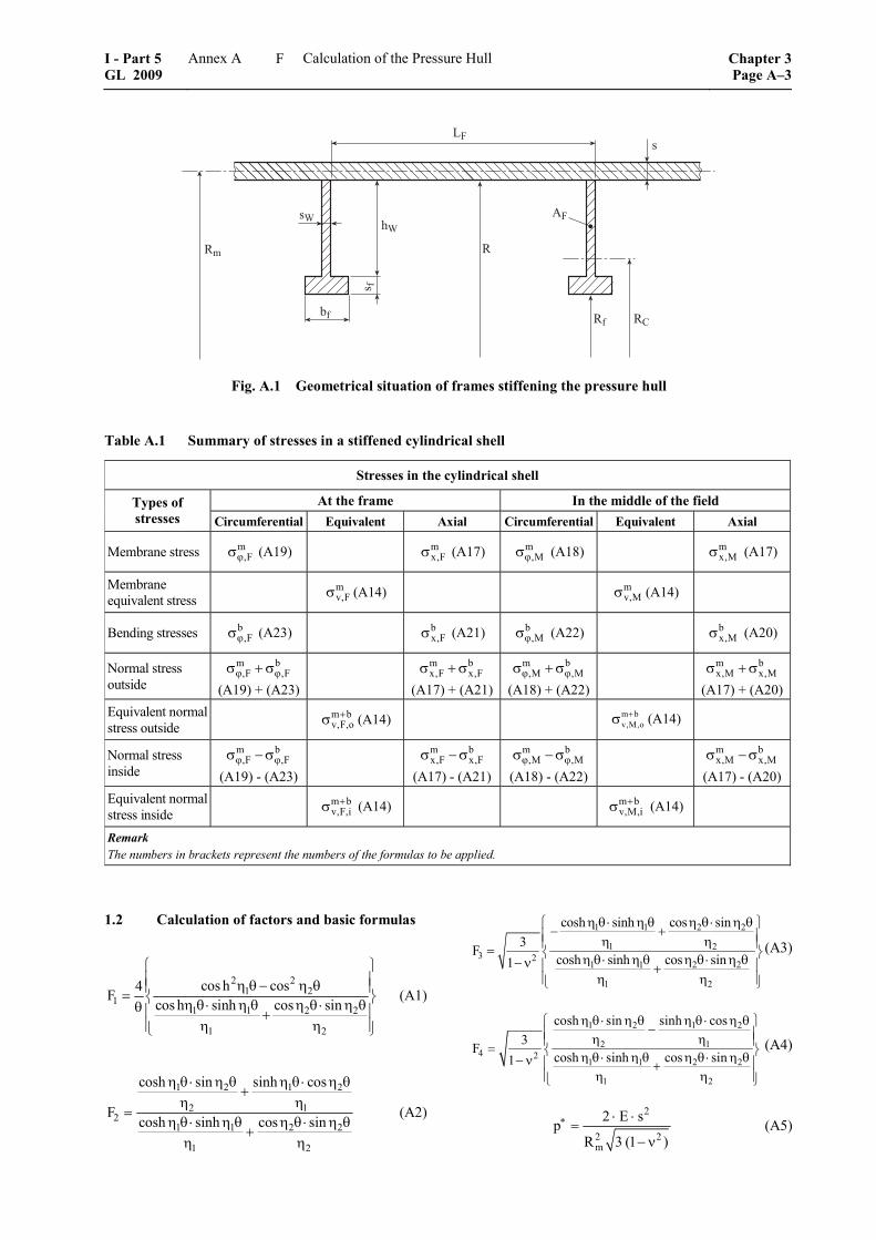
��
����
��
� �
��
�
�
�
Fig. A.1 Geometrical situation of frames stiffening the pressure hull
Table A.1 Summary of stresses in a stiffened cylindrical shell
Stresses in the cylindrical shell
At the frame In the middle of the field Types of stresses Circumferential Equivalent Axial Circumferential Equivalent Axial
Membrane stress m,Fϕσ (A19) m
x,Fσ (A17) m,Mϕσ (A18) m
x,Mσ (A17)
Membrane equivalent stress m
v,Fσ (A14) mv,Mσ (A14)
Bending stresses b,Fϕσ (A23) b
x,Fσ (A21) b,Mϕσ (A22) b
x,Mσ (A20)
Normal stress outside
m b,F ,Fϕ ϕσ + σ
(A19) + (A23)
m bx,F x,Fσ + σ
(A17) + (A21)
m b,M ,Mϕ ϕσ + σ
(A18) + (A22)
m bx,M x,Mσ + σ
(A17) + (A20)Equivalent normal stress outside m b
v,F,o+σ (A14) m b
v,M,o+σ (A14)
Normal stress inside
m b,F ,Fϕ ϕσ − σ
(A19) - (A23)
m bx,F x,Fσ − σ
(A17) - (A21)
m b,M ,Mϕ ϕσ − σ
(A18) - (A22)
m bx,M x,Mσ − σ
(A17) - (A20) Equivalent normal stress inside m b
v,F,i+σ (A14) m b
v,M,i+σ (A14)
Remark The numbers in brackets represent the numbers of the formulas to be applied.
1.2 Calculation of factors and basic formulas
2 21 2
11 1 2 2
1 2
cos h cos4Fcos h sinh cos sin
⎧ ⎫⎪ ⎪η θ − η θ⎪ ⎪= ⎨ ⎬η θ⋅ η θ η θ⋅ η θθ ⎪ ⎪+⎪ ⎪η η⎩ ⎭
(A1)
1 2 1 2
2 12
1 1 2 2
1 2
cosh sin sinh cos
Fcosh sinh cos sin
η θ⋅ η θ η θ⋅ η θ+
η η=
η θ⋅ η θ η θ⋅ η θ+
η η
(A2)
1 1 2 2
1 23 2
1 1 2 2
1 2
cosh sinh cos sin3F
cosh sinh cos sin1
η θ⋅ η θ η θ⋅ η θ⎧ ⎫− +⎪ ⎪η η⎪ ⎪= ⎨ ⎬η θ⋅ η θ η θ⋅ η θ− ν ⎪ ⎪+⎪ ⎪η η⎩ ⎭
(A3)
1 2 1 2
2 14 2
1 1 2 2
1 2
cosh sin sinh cos3F
cosh sinh cos sin1
η θ⋅ η θ η θ ⋅ η θ⎧ ⎫−⎪ ⎪η η⎪ ⎪= ⎨ ⎬η θ ⋅ η θ η θ⋅ η θ− ν ⎪ ⎪+⎪ ⎪η η⎩ ⎭
(A4)
2
2 2m
2 E spR 3 (1 )
∗ ⋅ ⋅=
− ν (A5)
I - Part 5 GL 2009
Annex A Calculation of the Pressure Hull Chapter 3Page A–3
F
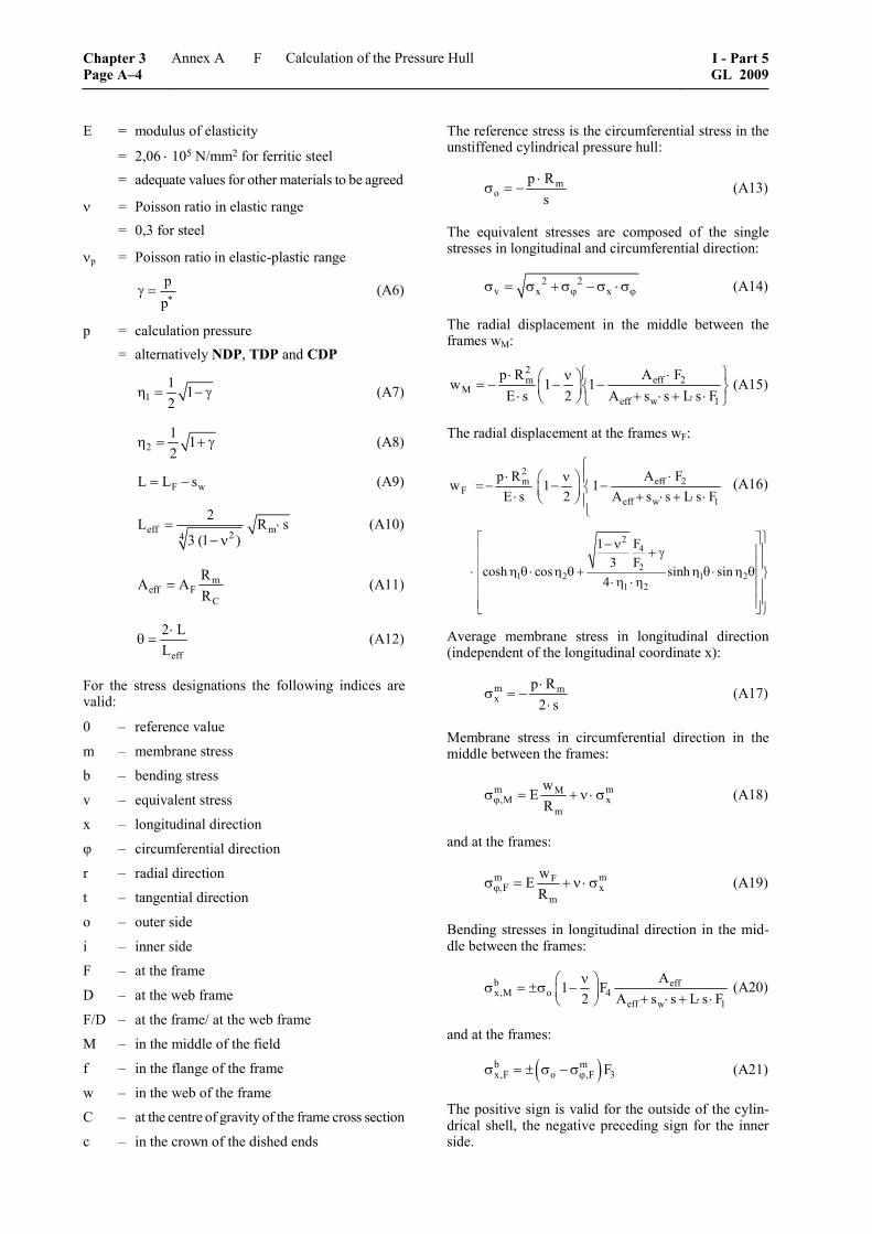
E = modulus of elasticity
= 2,06 ⋅ 105 N/mm2 for ferritic steel = adequate values for other materials to be agreed
ν = Poisson ratio in elastic range = 0,3 for steel
νp = Poisson ratio in elastic-plastic range
pp∗
γ = (A6)
p = calculation pressure = alternatively NDP, TDP and CDP
11 12
η = − γ (A7)
21 12
η = + γ (A8)
F wL L s= − (A9)
eff m24
2L R s3 (1 )
= ⋅− ν
(A10)
meff F
C
RA A
R= (A11)
eff
2 LL
⋅θ = (A12)
For the stress designations the following indices are valid:
0 – reference value
m – membrane stress
b – bending stress
v – equivalent stress
x – longitudinal direction
φ – circumferential direction
r – radial direction
t – tangential direction
o – outer side
i – inner side
F – at the frame
D – at the web frame
F/D – at the frame/ at the web frame
M – in the middle of the field
f – in the flange of the frame
w – in the web of the frame
C – at the centre of gravity of the frame cross section
c – in the crown of the dished ends
The reference stress is the circumferential stress in the unstiffened cylindrical pressure hull:
mo
p Rs
⋅σ = − (A13)
The equivalent stresses are composed of the single stresses in longitudinal and circumferential direction:
2 2v x xϕ ϕσ = σ + σ − σ ⋅σ (A14)
The radial displacement in the middle between the frames wM:
2eff 2m
Meff w 1
A Fp Rw 1 1
E s 2 A s s L s F⎧ ⎫⋅⋅ ν⎛ ⎞= − − −⎨ ⎬⎜ ⎟⋅ + ⋅ + ⋅ ⋅⎝ ⎠ ⎩ ⎭
(A15)
The radial displacement at the frames wF:
2eff 2m
Feff w 1
A Fp Rw 1 1E s 2 A s s L s F
⎧⋅⋅ ν⎛ ⎞ ⎪= − − −⎨⎜ ⎟⋅ + ⋅ + ⋅ ⋅⎝ ⎠ ⎪
⎩
(A16)
24
21 2 1 2
1 2
F13 F
cosh cos sinh sin4
⎫⎡ ⎤− ν ⎪⎢ ⎥+ γ⎪⎢ ⎥⋅ η θ ⋅ η θ + η θ⋅ η θ ⎬⎢ ⎥⋅η ⋅η ⎪⎢ ⎥⎪⎢ ⎥⎣ ⎦⎭
Average membrane stress in longitudinal direction (independent of the longitudinal coordinate x):
m mx
p R2 s⋅
σ = −⋅
(A17)
Membrane stress in circumferential direction in the middle between the frames:
m mM,M x
m
wE
Rϕσ = + ν ⋅ σ (A18)
and at the frames:
m mFF x
m
wE
Rϕ,σ = + ν ⋅ σ (A19)
Bending stresses in longitudinal direction in the mid-dle between the frames:
b effx,M o 4
eff w 1
A1 F
2 A s s L s Fν⎛ ⎞σ = ±σ −⎜ ⎟ + ⋅ + ⋅ ⋅⎝ ⎠
(A20)
and at the frames:
( )b mx,F o ,F 3Fϕσ = ± σ − σ (A21)
The positive sign is valid for the outside of the cylin-drical shell, the negative preceding sign for the inner side.
Chapter 3 Page A–4
Annex A Calculation of the Pressure Hull I - Part 5GL 2009
F
Bending stresses in circumferential direction in the middle between the frames:
b b,M x,Mϕσ = ν ⋅ σ (A22)
and at the frames:
b b,F x,Fϕσ = ν ⋅ σ (A23)
The circumferential stress follows from the radial displacement to:
m F,Fw
wE
Rϕσ = (A24)
in the frame foot,
respectively
m F,Ff
f
wE
Rϕσ = (A25)
in the frame flange.
The equivalent stresses as well as the circumferential stresses in the frame summarized in Table A.1 are to be limited with the value of the permissible stresses σzul,NDP, σzul,TDP resp. σzul,CDP belonging to each load case according to GL Rules for Manned Submersibles (I-5-2), Section 5, D.3.
1.3 Calculation of the stresses for a conical pressure hull
The formulas given above are also applicable to stiff-ened conical shells.
The relevant formulas have to be modified using the half apex angle α. For this, the mean radius yields to:
m,eqv mR R / cos= α (A26)
and the equivalent frame spacing turns to:
F,eqv F
eqv
L L / cos , resp.
L L / cos .
= α
= α (A27)
Rm = radius midway between the frames of the area under consideration
The calculation has to be carried out for both frames of the bay under evaluation. The dimensions of the frames have to be multiplied by the radius ratio Rm/Rm,F. For the following calculation of the collapse pressures the (absolutely) greatest value is decisive.
2. Calculation of the collapse pressure for the asymmetric interstiffener buckling of the shell in uniformly stiffened sections of the pressure hull
2.1 For conical pressure hulls the same values as defined for the stress calculation above are to be used.
For calculation of the minimum buckling pressure which depends on the number of circumferential lobes, the following approximation may be used:
2.2 Elastic buckling pressure
( ) ( )
m22 2elcr 2
m
R s2 E f s Lp
R 3 2 1 f3 1
⋅⎛ ⎞⋅ π ⋅ ⋅
= ⋅ ⋅⎜ ⎟ − ⋅Φ ⋅ −⋅Φ ⋅ − ν ⎝ ⎠ (A28)
Theoretical elastic-plastic pressure:
2
i el t scr cr 2
p
E E1 3 3p p 1E 4 E 41
− ν ⎧ Φ Φ ⎫⎛ ⎞= ⋅ ⋅ ⋅ − + ⋅⎨ ⎬⎜ ⎟− ν ⎝ ⎠⎩ ⎭ (A29)
with:
mR s1,23
L⋅
Φ = (A30)
mx
m,M
fϕ
σ=
σ (A31)
( ) ( )2 2m m m mv ,M x ,M xϕ ϕσ = σ + σ − σ ⋅σ (A32)
For secant module:
vs
vE
σ=
ε (A33)
For tangential module:
vt
v
dE
dσ
=ε
(A34)
For elastic-plastic Poisson's ratio:
sp
E0,5 (0,5 )
Eν = − − ν (A35)
f, σv, Es, Et are functions of the elastic-plastic buckling pressure pcr
i to be determined. For the iterative evalua-tion of pcr
i the value f can be computed for the calcula-tion pressure CDP and be assumed as constant in the following calculation. σv can be determined by linear extrapolation starting from the value of the calculation pressure CDP.
I - Part 5 GL 2009
Annex A Calculation of the Pressure Hull Chapter 3Page A–5
F
2.3 Secant module and tangential module of steels
For various types of steel is valid:
z = e
0,2
σσ
(A36)
σe = limit of proportional extension
σ0,2 = 0,2 % yield strength, ReH
z = 0,8 for ferritic steel
= 0,6 for austenitic steel
If σv > σe the formulas defined in 2.3.1 and 2.3.2 are valid.
For σv ≤ σe is valid:
Es = Et = E (A37)
2.3.1 Modules for z ≥ 0,8
2v 0,2
t0,2
zE E 1
(1 z)
⎧ ⎫⎛ ⎞σ − ⋅ σ⎪ ⎪= ⋅ − ⎜ ⎟⎨ ⎬⎜ ⎟− ⋅ σ⎪ ⎪⎝ ⎠⎩ ⎭ (A38)
vs
v 0,20,2
0,2
E Ez
z (1 z) arc tanh(1 z)
σ= ⋅
⎛ ⎞σ − ⋅σσ + −⎜ ⎟⎜ ⎟− ⋅σ⎝ ⎠
(A39)
2.3.2 Modules for z < 0,8
v 0,2t
0,2
zE E 1 k
(1 z)
⎧ ⎫⎛ ⎞σ − ⋅σ⎪ ⎪= ⋅ − ⎜ ⎟⎨ ⎬⎜ ⎟− ⋅ σ⎪ ⎪⎝ ⎠⎩ ⎭ (A40)
vs
v 0,20,2 0,2
0,2
E Ez1z (1 z) ln 1 k
k (1 z)
σ= ⋅
⎛ ⎞σ − ⋅σ⋅σ − − ⋅σ −⎜ ⎟⎜ ⎟− ⋅σ⎝ ⎠
(A41)
k has to be calculated from the condition:
0,2 0,2 0,210,002 E z (1 z) ln (1 k)k
σ + ⋅ = ⋅σ − − ⋅σ ⋅ − (A42)
at least with the accuracy of two decimals.
2.4 Secant modules and tangent modules for other metallic materials
For other metallic materials z is to be agreed.
2.5 It has to be proven, that the collapse pressure, which is the theoretical elastic-plastic buckling pres-sure pcr
i multiplied by the reduction factor r, is at least equal to the calculation pressure CDP of the pressure hull.
With the reduction factor:
elp1 cr 1i2 pcrr 1 0,25 e
⎛ ⎞⎜ ⎟− −⎜ ⎟⎝ ⎠= − ⋅ (A43)
3. Calculation of the collapse pressure for the symmetric interstiffener buckling of the shell in uniformly stiffened sections of the pressure hull
3.1 For conical pressure hulls the equivalent values as defined for the stress calculation above have to be used.
3.2 Elastic buckling pressure: 2 22
el effcr 22 effm
L2 s 2 L 1p EL 4 2 LR3(1 )
⎧ ⎫⎡ ⎤ ⎡ ⎤π⋅⋅⎪ ⎪= ⋅ ⋅ +⎨ ⎬⎢ ⎥ ⎢ ⎥π⋅ ⋅⎣ ⎦⎣ ⎦− ν ⎪ ⎪⎩ ⎭ (A44)
Theoretical elastic-plastic buckling pressure:
222icr s 22
m
2 s L 1p E C4 LR3(1 )
⎧ ⎫⎡ ⎤α⋅ π⎪ ⎪⎡ ⎤= ⋅ ⋅ ⋅ ⋅ +⎨ ⎬⎢ ⎥⎢ ⎥π α⋅⎣ ⎦ ⎣ ⎦− ν ⎪ ⎪⎩ ⎭(A45)
with:
222 12p 2
4 1 12 2m
A A3A A
R s
⎛ ⎞− ν⎜ ⎟⎜ ⎟
⎝ ⎠α =⋅
(A46)
2 21 2 p 12
2p
A A AC
1
⋅ − ν ⋅=
− ν (A47)
sp
E1 12 E 2
⎛ ⎞ν = − − ν⎜ ⎟⎝ ⎠
(A48)
2t s1 p p2 2
p
1 E / EA 1 (2 ) (1 2 ) k
4 (1 ) K H− ⎡ ⎤= − − ν − − ⋅ν⎣ ⎦− ν ⋅
(A49)
2t s2 p p2 2
p
1 E / EA 1 (1 2 ) (2 ) k
4 (1 ) K H− ⎡ ⎤= − − ⋅ν − − ν⎣ ⎦− ν ⋅
(A50)
t s12 p p2 2
p p
p p
1 E / EA 1 (2 ) (1 2 ) k
4 (1 )K H
(1 2 ) (2 ) k
− ⎡ ⎤= + − ν − − ⋅ν⎣ ⎦ν − ν ⋅
⎡ ⎤⋅ − ⋅ν − − ν⎣ ⎦
(A51)
( ) ( ) ( ){( )}
2t sp p2 2
p
2p
1 E / EH 1 2 1 2 k
4 1 K
3 1
− ⎡ ⎤= + − ν − − ⋅ν⎣ ⎦− ν
− − ν
(A52)
m,Mmx
k ϕσ=
σ (A53)
2 2K 1 k k= − + (A54)
The procedure for the evaluation of the theoretical elastic-plastic buckling pressure is analogous to that described for asymmetric buckling.
Chapter 3 Page A–6
Annex A Calculation of the Pressure Hull I - Part 5GL 2009
F
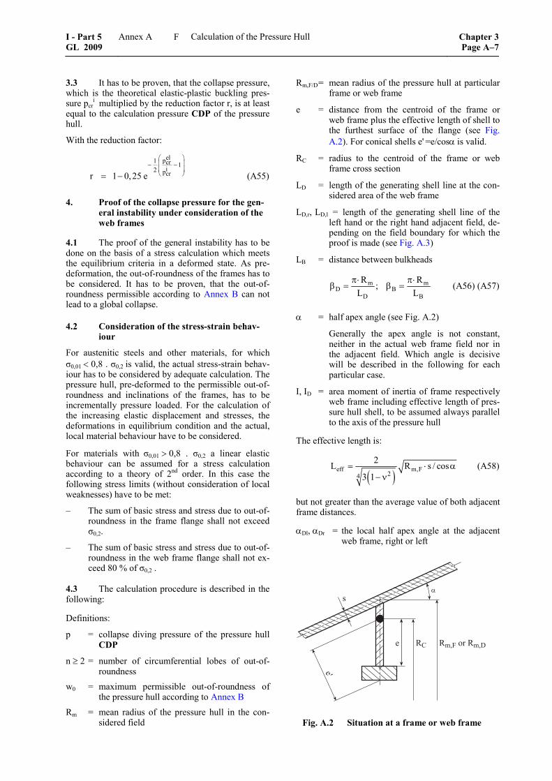
3.3 It has to be proven, that the collapse pressure, which is the theoretical elastic-plastic buckling pres-sure pcr
i multiplied by the reduction factor r, is at least equal to the calculation pressure CDP of the pressure hull.
With the reduction factor:
elp1 cr 1i2 pcrr 1 0,25 e
⎛ ⎞⎜ ⎟− −⎜ ⎟⎝ ⎠= − (A55)
4. Proof of the collapse pressure for the gen-eral instability under consideration of the web frames
4.1 The proof of the general instability has to be done on the basis of a stress calculation which meets the equilibrium criteria in a deformed state. As pre-deformation, the out-of-roundness of the frames has to be considered. It has to be proven, that the out-of-roundness permissible according to Annex B can not lead to a global collapse.
4.2 Consideration of the stress-strain behav-iour
For austenitic steels and other materials, for which σ0,01 < 0,8 . σ0,2 is valid, the actual stress-strain behav-iour has to be considered by adequate calculation. The pressure hull, pre-deformed to the permissible out-of-roundness and inclinations of the frames, has to be incrementally pressure loaded. For the calculation of the increasing elastic displacement and stresses, the deformations in equilibrium condition and the actual, local material behaviour have to be considered.
For materials with σ0,01 > 0,8 . σ0,2 a linear elastic behaviour can be assumed for a stress calculation according to a theory of 2nd order. In this case the following stress limits (without consideration of local weaknesses) have to be met:
– The sum of basic stress and stress due to out-of-roundness in the frame flange shall not exceed σ0,2.
– The sum of basic stress and stress due to out-of-roundness in the web frame flange shall not ex-ceed 80 % of σ0,2 .
4.3 The calculation procedure is described in the following:
Definitions:
p = collapse diving pressure of the pressure hull CDP
n ≥ 2 = number of circumferential lobes of out-of-roundness
w0 = maximum permissible out-of-roundness of the pressure hull according to Annex B
Rm = mean radius of the pressure hull in the con-sidered field
Rm,F/D = mean radius of the pressure hull at particular frame or web frame
e = distance from the centroid of the frame or web frame plus the effective length of shell to the furthest surface of the flange (see Fig. A.2). For conical shells e' =e/cosα is valid.
RC = radius to the centroid of the frame or web frame cross section
LD = length of the generating shell line at the con-sidered area of the web frame
LD,r, LD,l = length of the generating shell line of the left hand or the right hand adjacent field, de-pending on the field boundary for which the proof is made (see Fig. A.3)
LB = distance between bulkheads
m mD B
D B
R R;
L Lπ⋅ π⋅
β = β = (A56) (A57)
α = half apex angle (see Fig. A.2)
Generally the apex angle is not constant, neither in the actual web frame field nor in the adjacent field. Which angle is decisive will be described in the following for each particular case.
I, ID = area moment of inertia of frame respectively web frame including effective length of pres-sure hull shell, to be assumed always parallel to the axis of the pressure hull
The effective length is:
( )
eff m,F24
2L R s / cos3 1
= ⋅ α− ν
(A58)
but not greater than the average value of both adjacent frame distances.
αDl, αDr = the local half apex angle at the adjacent web frame, right or left
�
�
����������
�
Fig. A.2 Situation at a frame or web frame
I - Part 5 GL 2009
Annex A Calculation of the Pressure Hull Chapter 3Page A–7
F
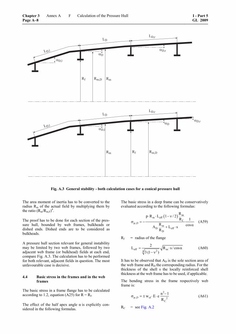
������
��
�����
����
����
����
����
��
� ����
����
��
����
����
Fig. A.3 General stability - both calculation cases for a conical pressure hull
The area moment of inertia has to be converted to the radius Rm of the actual field by multiplying them by the ratio (Rm/Rm,F)4.
The proof has to be done for each section of the pres-sure hull, bounded by web frames, bulkheads or dished ends. Dished ends are to be considered as bulkheads.
A pressure hull section relevant for general instability may be limited by two web frames, followed by two adjacent web frame (or bulkhead) fields at each end, compare Fig. A.3. The calculation has to be performed for both relevant, adjacent fields in question. The most unfavourable case is decisive.
4.4 Basic stress in the frames and in the web frames
The basic stress in a frame flange has to be calculated according to 1.2, equation (A25) for R = Rf.
The effect of the half apex angle α is explicitly con-sidered in the following formulas.
The basic stress in a deep frame can be conservatively evaluated according to the following formulas:
( ) m
m efff
mD eff
D
Rp R L 1 / 2R 1
R cosA L sR
⋅ ⋅ − νσ = −
α+ ⋅ϕ ,D (A59)
Rf = radius of the flange
eff m24
2L R s / cos3 (1 )
= ⋅ α− ν
(A60)
It has to be observed that AD is the sole section area of the web frame and RD the corresponding radius. For the thickness of the shell s the locally reinforced shell thickness at the web frame has to be used, if applicable.
The bending stress in the frame respectively web frame is:
2
el 2C
n 1w E eR
−σ = ± ⋅ ⋅ϕ ,D (A61)
RC = see Fig. A.2
Chapter 3 Page A–8
Annex A Calculation of the Pressure Hull I - Part 5GL 2009
F
The elastic deflection wel for the frames reads:
el 0 ng
pw wp p
=−
(A62)
and for web frames:
mel 0 n
m Dg
ppw wp pp p
=+−
(A63)
With the membrane part:
43
m2 2 2 2m
2E sp cosR (n 1 / 2) (n )
⋅ β= α
− + β + β
(A64)
α is the average half apex angle and s the average cylinder shell thickness in the considered field.
And with the web frame part pD:
2 3D
D 2C,D m m C,D D D,l / r
2
2 2B
2(n 1)E I cosp
R [R 4 (R R )] (L L )
n 1n 1 / 2
− ⋅ ⋅ α=
− − +
−⋅
− + β
(A65)
α is the maximum half apex angle along the pressure hull section starting at the middle of the field under consideration and ending at the middle of the adjacent field:
αmax = max(α; αDl) resp. αmax = max(α; αDr)
see Fig. A.3
RC,D applies to web frames.
The total instability pressure ngp has to be evaluated as
follows:
n m Dg F B
m D
p pp p p
p p⋅
= + ++
(A66)
using pm and pD as described above, and the frame part pF as well as the bulkhead part pB as follows:
2 24F
F 3 2 2 DC,F F
D m
(n 1)E I n 1p cosp1R L n 1
2 p p
− ⋅ −= α
⋅ − + β+
(A67)
RC,F applies to frames.
43 B
B 22 2 2 2mB B
E sp cosR (n 1 / 2) (n )
β⋅= α
− + β + β (A68)
α is here to be understood as the average half apex angle in the field considered.
The frame part has to be calculated with the dimen-sions of an equivalent frame including equivalent frame spacing. Generally these are the dimensions of the frame closest to the midway point of the field under evaluation, which have to be converted to the average field radius in a manner described in 1.3.
The following condition has to be met:
For each frame of the considered field the permissible out-of-roundness has to be calculated for n = 5, as-suming for pg
5 an infinitive field length (βD = 0). The arithmetic average of the out-of-roundness values evaluated in this way for three adjacent frames divided by the related frame radius shall not be less than the out-of-roundness for the equivalent frame evaluated in analogous way.
5. Proof of the collapse pressure for tripping of frames
5.1 Stability against tripping
The proof of the tripping stability has to be done for frames and web frames on the basis of a stress calcula-tion, which fulfils the status of equilibrium in de-formed condition. As pre-deformations the tolerances of the frames as defined in Annex B may be consid-ered.
Concerning the consideration of the stress-strain be-haviour the rules defined in 4.2 are valid.
For materials with σ0,01 ≥ 0,8 ⋅ σ0,2 linear elastic be-haviour can be assumed for a stress calculation ac-cording to 2nd order theory. The following stress limits have to be observed (disregarding local material weakening):
– The equivalent stress in frame web shall not exceed σ0,2.
– The circumferential stress in frame flange shall not exceed σ0,2.
The effects to be considered in this procedure are defined further on.
5.2 Additional stresses caused by frame imper-fections
The additional stresses caused by imperfections of the frame cross section have to be evaluated for internal frames according to the following formulas. See also Figure A.4.
The imperfections "inclination of web to plane of frame Θ", "eccentricity of flange to web uex" and "misalignment of frame heel to frame plane d" are defined in Annex B, C.2.5 to C.2.7.
fw w
sh h
2′ = + (A69)
I - Part 5 GL 2009
Annex A Calculation of the Pressure Hull Chapter 3Page A–9
F
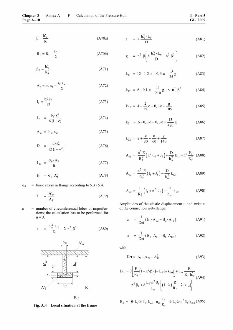
whR′
β = (A70a)
' ff f
sR R
2= + (A70b)
wf
f
hR
′β =
′ (A71)
f wf f f
s sA b s
2⋅
′ = − (A72)
3f f
fb s
I12⋅
= (A73)
3
f ff
b sJ
6 (1 )⋅
=+ ν
(A74)
w w wA h s′ ′= ⋅ (A75)
3w
2E s
D12 (1 )
⋅=
− ν (A76)
0 F0
AL
Rσ ⋅
= (A77)
f 0 fF A′= σ ⋅ (A78)
σ0 = basic stress in flange according to 5.3 / 5.4.
w
F
AA
′λ = (A79)
n = number of circumferential lobes of imperfec-tions; the calculation has to be performed for n = 3.
'2
2 2w 0h Le 2 n
D⋅
= − ⋅ ⋅β (A80)
��
��
��
� �
���
���
� ����
Fig. A.4 Local situation at the frame
'2w 0h LD⋅
ε = λ (A81)
'2
2 2 3w 0h Lg n n
D⎛ ⎞⋅
= ⋅β λ − ⋅β⎜ ⎟⎜ ⎟⎝ ⎠
(A82)
1113k 12 1,2 e 0,6 g35
= − ⋅ + ⋅ε − (A83)
2 212
11k 6 0,1 e g n210
= − ⋅ − + ν⋅ ⋅β (A84)
222 gk 4 e 0,1
15 105= − + ⋅ε − (A85)
3113k 6 0,1 e 0,1 g420
= − ⋅ + ⋅ε + (A86)
32e gk 2
30 60 140ε
= + − + (A87)
( )2
2 2 f11 f f 114 '3 2
f w f
Fn E DA n I J k nR h R
= ⋅ + + − (A88)
( )2
12 f f 123 '2f w
n E DA I J kR h
⋅= + − (A89)
( )222 f f 222 '
f w
E DA I n J kR h
= + ⋅ + (A90)
Amplitudes of the elastic displacement u and twist ω of the connection web-flange:
( )1 22 2 121u B A B A
Det= ⋅ − ⋅ (A91)
( )2 11 1 121 B A B A
Detω = ⋅ − ⋅ (A92)
with
211 22 12Det A A A= ⋅ − (A93)
( )
( )
2f f1 f 0 1, ex '
f f w
22 0 f
f 1,d'fw
F FB 1 n L k uR R h
L n Rn d 1 kRh
θ⎡ ⎤
= θ + ⋅β − ⋅λ⋅ +⎢ ⎥⋅⎣ ⎦
⎡ ⎤⋅ ⋅β⋅ ⋅β + − λ − λ⋅⎢ ⎥
⎣ ⎦
(A94)
' 2f2 0 w 2, ex 0 f 2,d
f
FB L h k u d L n k
Rθ= −θ⋅ ⋅λ⋅ ⋅ + − ⋅ ⋅λ⋅ ⋅β ⋅ (A95)
Chapter 3 Page A–10
Annex A Calculation of the Pressure Hull I - Part 5GL 2009
F
where:
)
21,
2
1k 1 0,013 g 0,015 e2 420
0,025 e 0,7 n
θε⎛= − − + ⋅ + ⋅⎜
⎝
− ⋅ ⋅ε − ⋅ ⋅β
(A96)
21,d
1k 1 0,013 g 0,015 e 0,025 e2 420
ε⎛ ⎞= − − + ⋅ + ⋅ − ⋅ ⋅ε⎜ ⎟⎝ ⎠
(A97)
22,
2
1 e gk 1 0,008 e12 60 105 140
19 e 250,013 e 0,6 n 11260 336
θε⎡= + − − − ⋅⎢⎣
⋅ ⋅ε ⎤⎛ ⎞+ ⋅ ⋅ε+ ⋅ ⋅β + +⎜ ⎟⎥⎝ ⎠⎦
(A98)
22,d
1 e gk 1 0,008 e 0,013 e12 60 105 140
ε⎛ ⎞= + − − − ⋅ + ⋅ ⋅ε⎜ ⎟⎝ ⎠
(A99)
Stresses in the flange are as follows:
( )b 2fr,F/ Df f2
f
E bn u R
2 R⋅
σ = ± ⋅ + ⋅ω⋅
(A100)
Bending stress around radial axis, and
( )
( )ft,F/ Df f2
f
n E s u R2 1 R
⋅ ⋅τ = + ⋅ω
+ ν (A101)
Torsion around the tangential axis, which is phase-shifted against b
r,F/ Dfσ by a quarter period.
The bending stress at the toe of the web is:
( )
( )
b 'r,F/ Dw 31 32 w2 '2
w w
' 20 3, w 3,d
6 D k u k hs h
L k h k n dθ
⎡σ = ± ⋅ − ⋅ ⋅ω⎢
⎢⎣
⎤+ λ ⋅ ⋅θ+ ⋅ ⋅β⋅ ⎥
⎦
(A102)
with
( )
23,
1 ek 1 0,4 n12 60 140
1 0,019 e 0,009
θε⎛= + − + ⋅ ⋅β⎜
⎝
⎞⋅ + ⋅ − ⋅ε ⎟⎠
(A103)
and
3,d1 ek 1
12 60 140ε⎛ ⎞= + −⎜ ⎟
⎝ ⎠ (A104)
The stresses resulting from imperfections of the frames are to be checked for frames and web frames, using different procedures.
5.3 Frames
For the stress σ0 always σ0,2 of the frame material has to be used.
The bending rigidity of the flange has to be neglected, i.e. set to zero (If = 0).
The equivalent stress at the web toe has to be evalu-ated with the calculation pressure for both signs of the bending stress b
r,Fwσ according to formula (A102).
Circumferential stress:
m b m b2,F ,Fw O / R r,Fw
1
ee
+ϕ ϕσ = σ + ⋅σ ± ν ⋅σ (A105)
with m,Fwϕσ according to 1.2, equation (A24), compare
Fig. A.5 and
mO/ R 0,2 ,Ffϕσ = σ + σ (A106)
with m,Ffϕσ according to 1.2, equation (A25)
Radial stress:
b0r r,Fw
w
Ls
σ = − ± σ (A107)
The equivalent stress:
2 2v r rϕ ϕσ = σ + σ − σ ⋅σ (A108)
shall not exceed σ0,2.
�
�������
�
Fig. A.5 Situation of the frame in relation to the axis of the pressure hull
I - Part 5 GL 2009
Annex A Calculation of the Pressure Hull Chapter 3Page A–11
F
5.4 Web frames
For the basic stress in the flange σ0 the absolute value of the circumferential stress ,Dϕσ according to for-
mula (A59) has to be taken, as obtained for the half value of the permissible out-of-roundness resulting from the general instability proof performed for n = 2 circumferential lobes according to 4.
It has to be proven that:
a) b0 r,Df 0,2σ + σ ≤ σ (A109)
b) 2 20 t,Df 0,23σ + ⋅ τ ≤ σ (A110)
with br,Dfσ according to formula (A100) and τt, Df
according to formula (A101) considering the relevant dimensions of the web frames
and the equivalent stress at the web toe
2 2v r r 0,2ϕ ϕσ = σ + σ − σ ⋅σ ≤ σ (A111)
The circumferential stress σφ is the sum of the basic stress σφ,D obtained with the formula (A59) in 4.4 and ν-times the web bending stress b
r,Dwσ according to formula (A102):
b,D r,Dwϕ ϕσ = σ + ν⋅σ (A112)
The radial stress is:
bf 0 w Dr r,Dw
D w
A AR s
− ⋅σ + ⋅σσ = ± σ
⋅ (A113)
For calculation of σ0 the following simplified formula can be used:
0 ,D 0,21 0,42 ϕσ = σ + ⋅σ (A114)
5.5 Modifications for frames arranged outside
For frames arranged outside all radii (R, Rf, RDf) have to be applied as negative values.
6. Spherical shells and dished ends
6.1 General
Spherical shells and dished ends are to be investigated for the load cases defined in GL Rules for Manned Submersibles (I-5-2), Section 4, E. respectively Un-manned Submersibles (ROV, AUV) and Underwater Working Machines (I-5-3), Section 3, C.1.6. against exceeding stresses and buckling. For dished ends the stresses in the crown and the knuckle are to be inves-tigated. Spheres are to be treated like the crown area of dished ends.
6.2 Stresses
For the crown area the stress results from formula (A118). For the knuckle area the stress can be evalu-ated by formula (A119). The coefficients β are to be determined according to the GL Rules for Machinery Installations (I-1-2), Section 7a, D.4.3.2. They can also be evaluated directly with assistance of the fol-lowing formulas:
For torispherical ends:
β = 0,6148 – 1,6589 ⋅ x – 0,5206 ⋅ x2 – 0,0571 ⋅ x3 (A115)
And for semi-ellipsoidal ends:
β = 1,3282 – 0,3637 ⋅ x – 0,1293 ⋅ x2 – 0,0171 ⋅ x3 (A116)
a
a
swith x lnD
sfor range of validity 0,001 0,1D
⎛ ⎞= ⎜ ⎟
⎝ ⎠
≤ ≤ (A117)
Da = outside diameter of the dished end
In the range 0,5 s R⋅ ⋅ besides the transition to the cylinder the coefficient β = 1,1 for hemispherical ends.
Under the assumption that deviations in the form of dished ends stay within the permissible tolerances, the stresses can be calculated with the following formulas. If the tolerances are exceeded, a separate proof of stress is to be performed.
2
c,o,l
c,m,l
R p2 R s
⋅σ = −
⋅ ⋅ (A118)
Rc,o,l = local outside radius of sphere crown of the dished end
Rc,m,l = local radius of the sphere crown of the dished end at half thickness of the shell
ap D 1, 24 s
⋅ ⋅ ⋅βσ = −
⋅ (A119)
For p NDP, TDP and CDP are to be introduced re-spectively.
The proof has been made if the permissible stresses according to the Rules for Manned Submersibles (I-5-2), Section 5, D.3. are not exceeded.
6.3 Calculation of the collapse pressure
The calculations are based on the local thickness and curvature of the shell and they are considering an out-of-roundness of the shell in the sense of a local flatten-ing up to maximum u = 0,218 ⋅ sl / Ro. This is valid for pressed spherical shells and is adequate to a local outside curvature radius of Ro,l = 1,3 ⋅ Ro of the outer nominal radius.
Chapter 3 Page A–12
Annex A Calculation of the Pressure Hull I - Part 5GL 2009
F
The out-of-roundness and herewith the local radius is to be evaluated with a bridge gauge as described in Annex B, E. There a measuring length Lcr,l according to formula (A120) has to be used. The out-of-roundness defined in this way is to be understood as local flattening from the theoretical form of the sphere within the diameter Lcr,l. For the lay out a local radius of 1,3 times the nominal radius and a nominal thick-ness of the shell (eventually reduced by the corrosion addition) is to be assumed. The corrosion addition shall be considered by keeping the outside radius.
If other tolerances are provided or another out-of-roundness is resulting from the measurement checks according to Annex B, E.3. or E.4., then a recalcula-tion of the permissible pressure according Annex B, E.5. is required.
For mechanically machined spherical shells local radii less than 1,05 ⋅ Ro are reachable from point of manu-facturing. The more favourable geometrical condition of the shell can be introduced in the calculation with at minimum Ro,l = 1,05 ⋅ Ro under the assumption that the measurement procedure, as described in Annex B, has proven a maximum permissible local flattening of u = 0,035 ⋅ s1 / Ro with an accuracy of at least 0,001 ⋅ s.
6.4 Definitions
The following definitions are valid:
Rm,l = maximum local mean radius of curvature of the sphere at shell half thickness
R0,1 = maximum local outside radius of curvature of the sphere
s = nominal thickness of the shell
s1 = local average shell thickness
Critical arc length or diameter of the measuring circle to be used for measuring the deviations from the per-fect form of the sphere according to Annex B, E.3. and E.4.:
cr,l o,l l24
2,2L R s3 (1 )4
= ⋅ ⋅⋅ − ν
(A120)
Elastic buckling pressure of the sphere:
2
el lcr 2 o,l
s1,4p ER3 (1 )
⎛ ⎞= ⋅ ⋅⎜ ⎟⎜ ⎟⋅ − ν ⎝ ⎠
(A121)
Theoretical elastic-plastic buckling pressure of the sphere:
t si elcr cr
E Ep p
E⋅
= ⋅ (A122)
0,2 l m,l0,2 2
o,l
2 s Rp
R
⋅σ ⋅ ⋅= (A123)
6.5 Spherical ends made of ferritic steel
For spherical ends made of ferritic steel grade GL-M550 or similar material pcr can be calculated as fol-lows:
6.5.1 For spherical ends which are not stress re-lieved the following is valid:
elcr crp p= if
elcr
0,2
p0,47
p≤ (A124)
elcr
cr 0,20,2
elcr
0,2
pp p 0,38 0,195
p
pif 0, 47 3,18
p
⎛ ⎞= +⎜ ⎟⎜ ⎟
⎝ ⎠
< ≤
(A125)
cr 0,2p p= if elcr
0,2
p3,18
p> (A126)
6.5.2 For stress relieved spherical ends (tempered and stress relieved) the following is valid:
elcr crp p= if
elcr
0,2
p0,595
p≤ (A127)
elcr
cr 0,20,2
elcr
0,2
pp p 0,475 0,195
p
pif 0,595 2,7
p
⎛ ⎞= +⎜ ⎟⎜ ⎟
⎝ ⎠
< ≤
(A128)
cr 0,2p p= if elcr
0,2
p2,7
p> (A129)
The fabrication of ends by welding of stress relieved segments and the welding of the penetrations into the shell after stress relieving is permitted.
The calculated collapse pressure pcr shall be at least equal to the collapse diving pressure CDP of the pres-sure hull.
6.6 Spherical shells of other materials
For spherical ends made of other steel materials the elastic-plastic buckling pressure i
crp which has been evaluated according to the formulas described above has to be multiplied by the reduction factor k defined in Fig. A.6. The reduction factor k is also summarized in tabular form in Table A.2. Intermediate values can be defined by linear interpolation.
For the application of non-iron metal materials the reduction factors are to be evaluated in accordance with GL by model tests.
I - Part 5 GL 2009
Annex A Calculation of the Pressure Hull Chapter 3Page A–13
F
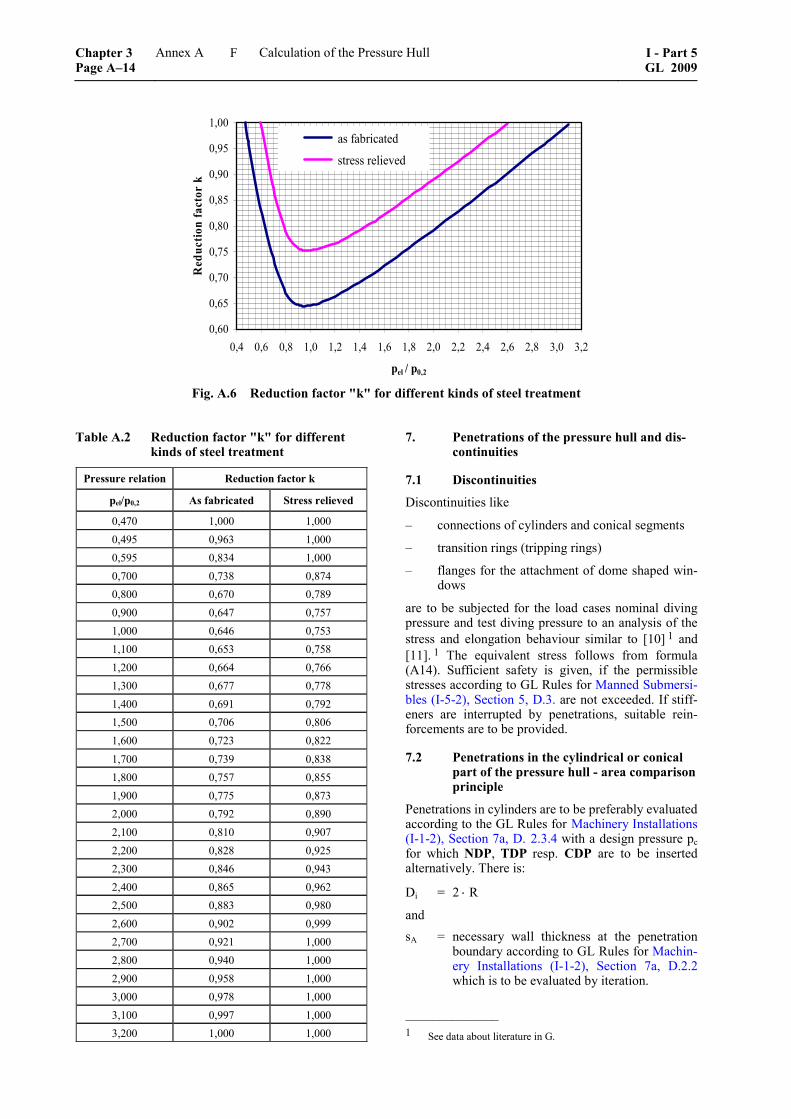
0,60
0,65
0,70
0,75
0,80
0,85
0,90
0,95
1,00
0,4 0,6 0,8 1,0 1,2 1,4 1,6 1,8 2,0 2,2 2,4 2,6 2,8 3,0 3,2
pel / p0,2
Red
uctio
n fa
ctor
k
as fabricated
stress relieved
Fig. A.6 Reduction factor "k" for different kinds of steel treatment
Table A.2 Reduction factor "k" for different kinds of steel treatment
Pressure relation Reduction factor k
pel/p0,2 As fabricated Stress relieved
0,470 1,000 1,000 0,495 0,963 1,000 0,595 0,834 1,000 0,700 0,738 0,874 0,800 0,670 0,789 0,900 0,647 0,757 1,000 0,646 0,753 1,100 0,653 0,758 1,200 0,664 0,766 1,300 0,677 0,778 1,400 0,691 0,792 1,500 0,706 0,806 1,600 0,723 0,822 1,700 0,739 0,838 1,800 0,757 0,855 1,900 0,775 0,873 2,000 0,792 0,890 2,100 0,810 0,907 2,200 0,828 0,925 2,300 0,846 0,943 2,400 0,865 0,962 2,500 0,883 0,980 2,600 0,902 0,999 2,700 0,921 1,000 2,800 0,940 1,000 2,900 0,958 1,000 3,000 0,978 1,000 3,100 0,997 1,000 3,200 1,000 1,000
7. Penetrations of the pressure hull and dis-continuities
7.1 Discontinuities
Discontinuities like
– connections of cylinders and conical segments
– transition rings (tripping rings)
– flanges for the attachment of dome shaped win-dows
are to be subjected for the load cases nominal diving pressure and test diving pressure to an analysis of the stress and elongation behaviour similar to [10] 1 and [11]. 1 The equivalent stress follows from formula (A14). Sufficient safety is given, if the permissible stresses according to GL Rules for Manned Submersi-bles (I-5-2), Section 5, D.3. are not exceeded. If stiff-eners are interrupted by penetrations, suitable rein-forcements are to be provided.
7.2 Penetrations in the cylindrical or conical part of the pressure hull - area comparison principle
Penetrations in cylinders are to be preferably evaluated according to the GL Rules for Machinery Installations (I-1-2), Section 7a, D. 2.3.4 with a design pressure pc for which NDP, TDP resp. CDP are to be inserted alternatively. There is:
Di = 2 ⋅ R
and sA = necessary wall thickness at the penetration
boundary according to GL Rules for Machin-ery Installations (I-1-2), Section 7a, D.2.2 which is to be evaluated by iteration.
–––––––––––––– 1 See data about literature in G.
Chapter 3 Page A–14
Annex A Calculation of the Pressure Hull I - Part 5GL 2009
F
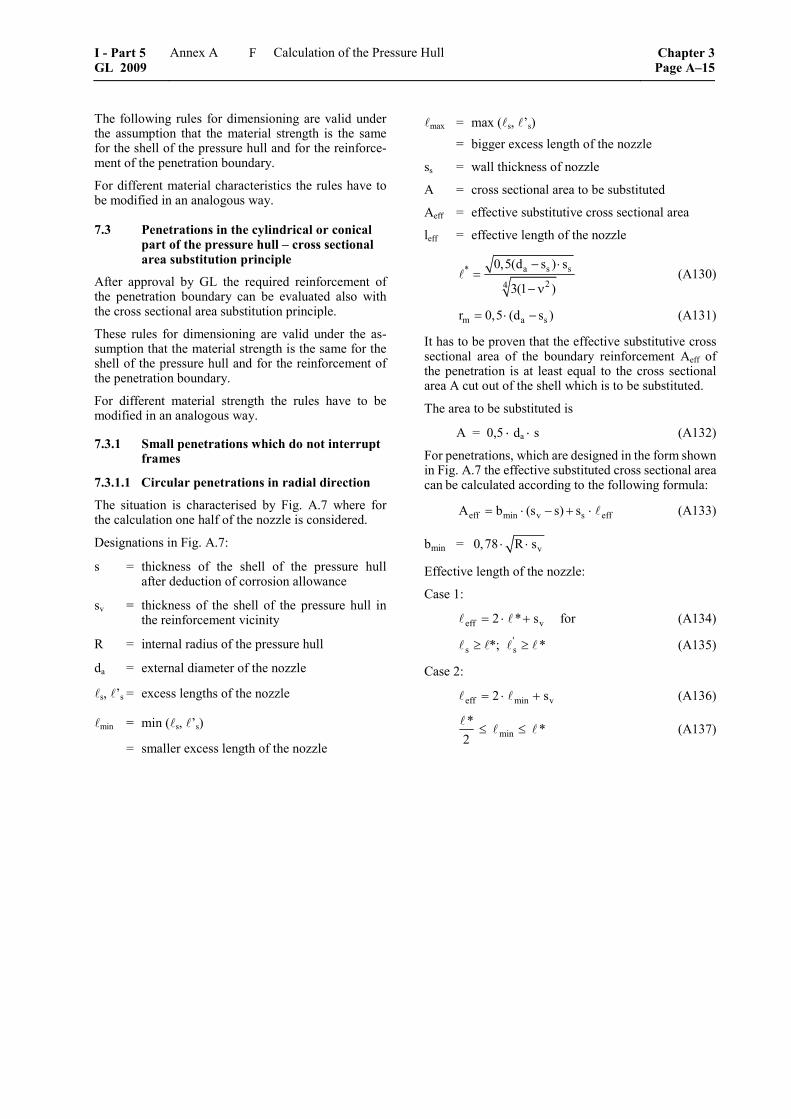
The following rules for dimensioning are valid under the assumption that the material strength is the same for the shell of the pressure hull and for the reinforce-ment of the penetration boundary.
For different material characteristics the rules have to be modified in an analogous way.
7.3 Penetrations in the cylindrical or conical part of the pressure hull – cross sectional area substitution principle
After approval by GL the required reinforcement of the penetration boundary can be evaluated also with the cross sectional area substitution principle.
These rules for dimensioning are valid under the as-sumption that the material strength is the same for the shell of the pressure hull and for the reinforcement of the penetration boundary.
For different material strength the rules have to be modified in an analogous way.
7.3.1 Small penetrations which do not interrupt frames
7.3.1.1 Circular penetrations in radial direction
The situation is characterised by Fig. A.7 where for the calculation one half of the nozzle is considered.
Designations in Fig. A.7:
s = thickness of the shell of the pressure hull after deduction of corrosion allowance
sv = thickness of the shell of the pressure hull in the reinforcement vicinity
R = internal radius of the pressure hull
da = external diameter of the nozzle
s, ’s = excess lengths of the nozzle
min = min ( s, ’s)
= smaller excess length of the nozzle
max = max ( s, ’s) = bigger excess length of the nozzle
ss = wall thickness of nozzle
A = cross sectional area to be substituted
Aeff = effective substitutive cross sectional area
leff = effective length of the nozzle
a s s*24
0,5(d s ) s
3(1 )
− ⋅=
− ν (A130)
m a sr 0,5 (d s )= ⋅ − (A131)
It has to be proven that the effective substitutive cross sectional area of the boundary reinforcement Aeff of the penetration is at least equal to the cross sectional area A cut out of the shell which is to be substituted.
The area to be substituted is
A = 0,5 ⋅ da ⋅ s (A132)
For penetrations, which are designed in the form shown in Fig. A.7 the effective substituted cross sectional area can be calculated according to the following formula:
eff min v s effA b (s s) s= ⋅ − + ⋅ (A133)
bmin = v0,78 R s⋅ ⋅
Effective length of the nozzle:
Case 1:
eff v2 * s= ⋅ + for (A134)
's s*; *≥ ≥ (A135)
Case 2:
eff min v2 s= ⋅ + (A136)
min* *
2≤ ≤ (A137)
I - Part 5 GL 2009
Annex A Calculation of the Pressure Hull Chapter 3Page A–15
F
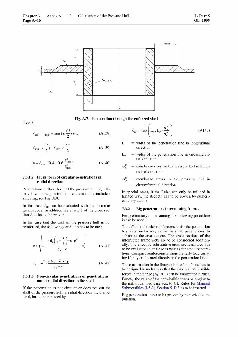
�
��
��
��������
��
��
����
Fig. A.7 Penetration through the enforced shell Case 3:
eff min v*min (a, ) s
2= + + (A138)
min max* *;
2 2< > (A139)
2min
max 2max
a (0,4 0,6 )= + (A140)
7.3.1.2 Flush form of circular penetrations in radial direction
Penetrations in flush form of the pressure hull ( s = 0), may have in the penetration area a cut out to include a zinc ring, see Fig. A.8.
In this case eff can be evaluated with the formulas given above. In addition the strength of the cross sec-tion A-A has to be proven.
In the case that the wall of the pressure hull is not reinforced, the following condition has to be met:
2a
2
a
ss d g c g2c 4 c
d c τ
⎛ ⎞⋅ − − ⋅⎜ ⎟⎝ ⎠> ⋅ +
− (A141)
a
a
s d 2 c gc 3
d cτ⋅ − ⋅ ⋅
= ⋅−
(A142)
7.3.1.3 Non-circular penetrations or penetrations not in radial direction to the shell
If the penetration is not circular or does not cut the shell of the pressure hull in radial direction the diame-ter da has to be replaced by:
mx
a x md max L , Lϕϕ
⎛ ⎞σ⎜ ⎟= ⋅⎜ ⎟σ⎝ ⎠
(A143)
Lx = width of the penetration line in longitudinal direction
Lϕ = width of the penetration line in circumferen-tial direction
mxσ = membrane stress in the pressure hull in longi-
tudinal direction mϕσ = membrane stress in the pressure hull in
circumferential direction
In special cases, if the Rules can only be utilized in limited way, the strength has to be proven by numeri-cal computation.
7.3.2 Big penetrations interrupting frames
For preliminary dimensioning the following procedure is can be used:
The effective border reinforcement for the penetration has, in a similar way as for the small penetrations, to substitute the area cut out. The cross sections of the interrupted frame webs are to be considered addition-ally. The effective substitutive cross sectional area has to be evaluated in analogous way as for small penetra-tions. Compact reinforcement rings are fully load carry-ing if they are located directly in the penetration line.
The construction in the flange plane of the frame has to be designed in such a way that the maximal permissible forces in the flange (Af ⋅ σzul) can be transmitted further. For σzul the value of the permissible stress belonging to the individual load case acc. to GL Rules for Manned Submersibles (I-5-2), Section 5, D.3. is to be inserted.
Big penetrations have to be proven by numerical com-putation.
Chapter 3 Page A–16
Annex A Calculation of the Pressure Hull I - Part 5GL 2009
F
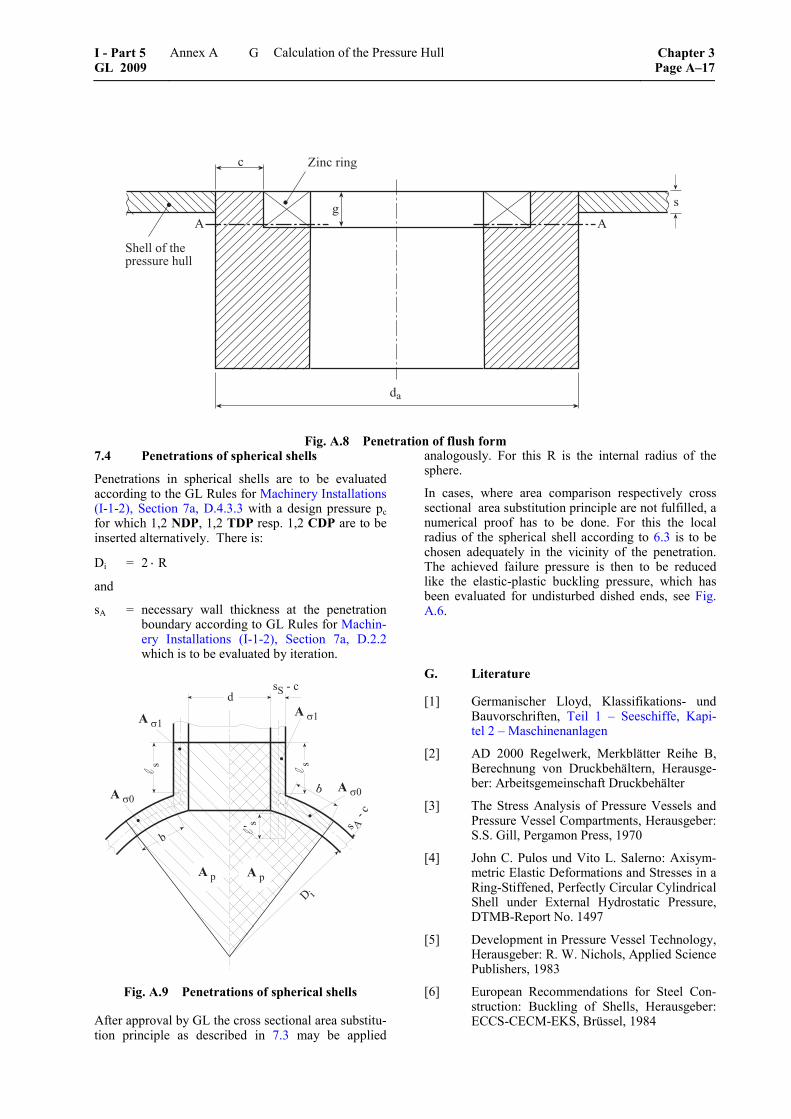
��
�
!�������
� �
�
"� ������#� $� ��%� ��%��
Fig. A.8 Penetration of flush form 7.4 Penetrations of spherical shells
Penetrations in spherical shells are to be evaluated according to the GL Rules for Machinery Installations (I-1-2), Section 7a, D.4.3.3 with a design pressure pc for which 1,2 NDP, 1,2 TDP resp. 1,2 CDP are to be inserted alternatively. There is:
Di = 2 ⋅ R
and
sA = necessary wall thickness at the penetration boundary according to GL Rules for Machin-ery Installations (I-1-2), Section 7a, D.2.2 which is to be evaluated by iteration.
� �
��$ ��$
����
���&���&
�����
�"�'��
�
�
�
� ��'��
� �
�
Fig. A.9 Penetrations of spherical shells
After approval by GL the cross sectional area substitu-tion principle as described in 7.3 may be applied
analogously. For this R is the internal radius of the sphere.
In cases, where area comparison respectively cross sectional area substitution principle are not fulfilled, a numerical proof has to be done. For this the local radius of the spherical shell according to 6.3 is to be chosen adequately in the vicinity of the penetration. The achieved failure pressure is then to be reduced like the elastic-plastic buckling pressure, which has been evaluated for undisturbed dished ends, see Fig. A.6.
G. Literature
[1] Germanischer Lloyd, Klassifikations- und Bauvorschriften, Teil 1 – Seeschiffe, Kapi-tel 2 – Maschinenanlagen
[2] AD 2000 Regelwerk, Merkblätter Reihe B, Berechnung von Druckbehältern, Herausge-ber: Arbeitsgemeinschaft Druckbehälter
[3] The Stress Analysis of Pressure Vessels and Pressure Vessel Compartments, Herausgeber: S.S. Gill, Pergamon Press, 1970
[4] John C. Pulos und Vito L. Salerno: Axisym-metric Elastic Deformations and Stresses in a Ring-Stiffened, Perfectly Circular Cylindrical Shell under External Hydrostatic Pressure, DTMB-Report No. 1497
[5] Development in Pressure Vessel Technology, Herausgeber: R. W. Nichols, Applied Science Publishers, 1983
[6] European Recommendations for Steel Con-struction: Buckling of Shells, Herausgeber: ECCS-CECM-EKS, Brüssel, 1984
I - Part 5 GL 2009
Annex A Calculation of the Pressure Hull Chapter 3Page A–17
G
[7] DIN 4114, Blatt 2: Stabilitätsfälle (Knickung, Kippung, Beulung), Ausgabe 2.53
[8] Myron E. Lunchick: Plastic Axisymmetric Buckling of Ring-Stiffened Cylindrical Shells Fabricated from Strainhardening Materials and Subjected to External Hydrostatic Pres-sure, DTMB-Report No. 1393
[9] Krenske, Martin A. und Kierman, Thomas J.: The Effect of Initial Imperfections on the Collapse Strength of Sherical Shells, DTMB-Report No. 1757
[10] ASME Boiler and Pressure Vessel Code, Section VIII, Division 2
[11] Raymond J. Roark and Warren C. Young: Formulars for Stress and Strain, Mc Graw -Hill Book Company
[12] William F. Blumenberg: The Effect of Inter-mediate Heavy Frames on the Elastic Gen-eral-Instability Strength of Ring-Stiffened Cylinders Under External Hydrostatic Pres-sure, DTMB-Report No. 1844
[13] Thomas E. Reynolds: Inelastic Lobar Buck-ling of Cylindrical Shells Under External Hy-drostatic Pressure, DTMB-Report No. 1392.
Chapter 3 Page A–18
Annex A Calculation of the Pressure Hull I - Part 5GL 2009
G
Annex B
Manufacturing Tolerances for the Pressure Hull
A. General
1. This Annex describes the permissible manu-facturing tolerances for the pressure hull as prerequi-site for the application of the strength calculations defined in Annex A.
2. All tests are to be performed by the manufac-turer in presence of a GL Surveyor and a measurement report has to be sent by the manufacturer to GL.
3. The required checks defined in the following are only to be performed, if no following changes of the measurement values are to be expected. Areas with welding seams which have been worked over in the mean time because of impermissible defects have to be measured again.
The component to be investigated shall be cooled down to ambient temperature and is so to be relieved from any tensions by means of installation aids in order to prevent falsification of the measurement results.
B. Dimensions of the Pressure Hull
1. General
1.1 As far as not defined otherwise in these Rules the following tolerances are valid.
1.2 All longitudinal and circumferential seams in the pressure hull plating shall be inspected for edge off-set, weld sinkage, undercuts and hollow grinding. This shall also be valid for the welding connection of the plating with the tripping/transition ring. The inner and outer surface of the plates is to be inspected for damage.
2. Dimensions of the cylindrical and conical parts
2.1 Diameter
The actual mean outside diameter of cylindrical re-spectively conical pressure hulls shall, calculated from the circumference, deviate not more than ± 0,5 % from the outside diameter on which the calculation is based. The measurements are to be performed in distances of maximum 3 R s⋅ ⋅ over the complete length of the component.
s = nominal shell thickness [mm]
R = internal radius of the shell [mm]
2.2 Generating line
The deviation of the theoretical generating line from the straight line shall not exceed ± 0,2 % of the length of the straight forward part of a cylinder resp. cone over three adjacent measuring points, which are given by web frames, bulkheads and connections of cones and dished ends. If web frames, cones and bulkheads are not provided, only between dished ends is to be meas-ured. The deviation is to be measured at minimum 8 positions equally distributed over the circumference.
2.3 Length
The length of the pressure hull rings in manufacturing is to be measured at minimum 4 positions equally distributed over the circumference and to be averaged.
The allowable tolerance of the length of the pressure hull ring shall not be bigger than the sum of the exist-ing deviations of the frame distances within this ring. If no frames are provided, the tolerance is ± 1 % of the nominal length, but not more than 15 mm.
3. Dimensions of spherical shells and dished ends
3.1 Radius of spherical shells and crown of dished ends
For determination of the spherical form of the spheri-cal shell the outside radius is to be evaluated accord-ing to E.3.
The spherical form of the spherical shell has to remain within a tolerance of ± 1 % of the nominal outside radius.
3.2 Course of theoretical geometry lines of dished ends (knuckle/crown radius)
The tolerances are to be defined by the manufacturer according to recognized regulations and deviations from it are to be approved by GL, compare E.2.
4. Component thickness
Tolerances for components of the pressure hull: –0/+t
Tolerance value t according to material delivery speci-fications (if the material delivery standard allows minus tolerances, these are to be considered for the calculations)
5. Edge offset and weld sinkage
5.1 The radial deviations x1 and x2 are the basis for the determination of weld sinkage and edge offset
I - Part 5 GL 2009
Annex B Manufacturing Tolerances for the Pressure Hull Chapter 3Page B–1
B
of sheet metal surfaces with regard to their nominal positions next to a welding seam, compare Fig. B.1. They are measured at a distance v = smax + 20 mm on both sides centred over the welding seam.
5.2 The tolerances for the gradient of the theo-retical line of the middle plane at the tripping/transi-tion ring are to be documented in the manufacturing protocols and to be checked.
5.3 Edge offset for cylindrical and conical parts
The edge offset of both plates which is determined by the difference of the measuring values │x2 – x1│, compare Fig. B.1.
For circumferential seams the edge offset shall not exceed 15 % of the nominal thickness of the thinner plate, but maximum 4 mm.
For longitudinal seams the edge offset shall not ex-ceed 10 % of the nominal thickness of the thinner plate, but maximum 3 mm.
��������������
�� �
Fig. B.1 Radial deviation of the sheet metal surface of the pressure hull
5.4 Edge offset for spherical shells and dished ends
For butt joints within these shells and dished ends the edge offset shall not exceed 10 % of the nominal thickness of the thinner plate, but maximum 3 mm.
5.5 Weld sinkage for cylindrical and conical parts
The mean value of the deviations
h = (x1 + x2) / 2
is defined as weld sinkage. If not otherwise agreed with GL, the following tolerances are valid:
For circumferential seams the weld sinkage shall not exceed h = ¼ ⋅ s, but maximum 5 mm.
For longitudinal seams the weld sinkage shall not exceed h ≤ 1/6 ⋅ s, but not more than 3 mm.
5.6 Weld sinkage for spherical shells and dished ends
For butt joints within these shells and dished ends the weld sinkage shall not exceed h = 1/6 ⋅ s, but maxi-mum 3 mm.
6. Damages to the component surface
Damage to the surface, such as scores, scratches, arc strikes, indentation pits, etc. shall be thoroughly smoothed and inspected for surface cracks. The flaws treated in this way are permissible without proof of strength, if the following requirements are met:
– The depth shall at maximum 0,05 ⋅ s or 3 mm, the smaller value is decisive.
– The area of the undercut of the thickness shall be within a circular area with 2 ⋅ s as diameter or 60 mm, the smaller value is decisive.
– The distance between two areas of thickness undercut and the distance from points of disturb-ance, like e.g. penetrations, shall be at least
2 R s⋅ ⋅ .
Deeper flaws are to be treated specially in agreement with GL.
7. Evaluation of the welding seams
The evaluation of other imperfections on welding seams as defined under 5. shall be performed accord-ing to the GL Rules for Design, Fabrication and In-spection of Welding Joints (II-3-2), Annex A, quality level B.
C. Pressure Hull Frames
1. Measurements
The following measurements shall be carried out on every frame of the pressure hull at eight measuring points uniformly distributed around the circumference:
– flange width
– flange thickness
– web thickness
– frame spacing (measured at frame heel)
– frame height at frame moulding edge
– eccentricity flange to web
– web tilt to plane of frame
The spacing k of the frame heel from a reference plane shall be determined by direct measurement, see Fig. B.2. The location of the frame heel is shown as detail "A" in this Figure. For cylindrical pressure hull parts this measurement shall be carried out on a minimum of one frame per ring (with a ring length of up to a maximum of 8 pressure hull frames) and for conical pressure hull parts on every frame at 16 points uni-formly distributed around the circumference.
Chapter 3 Page B–2
Annex B Manufacturing Tolerances for the Pressure Hull I - Part 5GL 2009
C
�������
�
�
����
��������������� �
Fig. B.2 Definition of the reference plane of a frame
2. Tolerances
2.1 The following tolerances are maximum val-ues and shall not be exceeded. The tolerances calcu-lated from percentages may be rounded up to half of a millimetre.
2.2 Flange width: 0 % to + 4,5 % Flange thickness: 0 mm to + 3 mm Web thickness: 0 mm to + 3 mm
With regard to the flange width resp. flange thickness the nominal cross sectional area of the flange is consid-ered to be a permissible acceptance criteria. Height tol-erances of 0,2 + 0,04 ⋅ s ≤ 1 mm (s = material thickness in mm) due to flat grinding of nicks may be exceeded locally, however, the nominal cross section of the flange or web shall not be reduced to more than 90 %.
2.3 Frame spacing: generally ± 1 % At circumferential seams
+1 % to –3 %
2.4 Frame height at frame moulding edge: 0 % to + 5 %
Tolerances up to –2 % are allowed locally if the mean value of the 8 measuring points reaches nominal value.
2.5 Eccentricity of flange to web: 2 % of frame height
2.6 Inclination of web to reference plane of frame: ± 2 °
2.7 Misalignment of frame heel to reference plane: + 4 mm for frames ± 6 mm for web frames
If the maximum difference of determined spacings (kmax – kmin) is larger than 8 mm for frames and 12 mm for web frames, the real deviations of h shall be deter-mined by evaluation according to the following formula:
hi = ki – k0 – Δkx ⋅ sin ϕi – Δky ⋅ cos ϕi (B1)
k0 = 1/J (k1 + k2 + k3 + ……kJ) (B2)
Δkx = 2/J (k1 ⋅ sin ϕ1 + k2 ⋅ sin ϕ2
+ k3 ⋅ sin ϕ3 + ……+ kJ ⋅ sin ϕJ ) (B3)
Δky = 2/J (k1 ⋅ cos ϕ1 + k2 ⋅ cos ϕ2
+ k3 ⋅ cos ϕ3 + ……+ kJ ⋅ cos ϕJ ) (B4)
ϕi = 360° ⋅ i /J
hi = deviation of the frame heel from the actual plane of frame at measuring point i
ki = measured distance of frame heel from the reference plane of measuring point i
J = number of measuring points
3. Transition rings and strengthening of pressure hull
Transition rings, strengthenings of cut-outs and other strengthenings of the pressure hull are not to be ap-plied with tolerances which weaken the components.
D. Out-of Roundness of the Cylindrical resp. Conical Pressure Hull
1. The out-of-roundness shall be measured at each frame and also at each transition ring. The meas-urements are to be conducted with a maximum dis-tance according to 3 R s⋅ ⋅ over the complete length of the component. For frame spacings above 3 R s⋅ ⋅ the out-of-roundness is to be determined also at the shell between the frames considering this measuring distance.
Moreover the course of the theoretical geometry lines at the transition ring is to be determined.
2. The following requirements shall be met prior to conducting out-of-roundness measurements:
I - Part 5 GL 2009
Annex B Manufacturing Tolerances for the Pressure Hull Chapter 3Page B–3
D
– The required tests shall only be carried out when no subsequent changes of measured values are to be expected.
– The section is to be cooled down to ambient temperature and relieved from any tension by means of appropriate aids in order to prevent falsification of measurement results.
3. The measurement of the pressure hull can be carried out from outside or from inside. In principle the measurement of out-of-roundness shall be carried out at 24 points distributed as uniformly as possible around the circumference. It can be conducted with the help of a circular template, callipers, a two point bridge gage (see Fig. B.4), photogrammetry or theodolite methods, in which case access has to be provided by appropriate means. If the measuring of individual values is not possible due to constructional reasons (e.g. in the area of larger openings), it shall be supplemented as far as practically possible (in general by linear interpolation). The measurement shall not be impaired by welding seams (e.g. weld reinforcement) or local imperfections on the surface.
4. The results of the evaluation shall be pre-sented to GL as tables and graphs.
5. The maximum permissible out-of-roundness is ± 0,5 % of the nominal pressure hull diameter unless otherwise agreed by GL.
6. Measuring method 1: direct measurement of the radii and their deviation from con-stant radius; from inside or from outside
The measurement can be performed from inside - measurement of the radii, and from outside - measure-
ment of the deviations from the constant, mean radius by rotating the pressure hull around an assumed axis (centre). The assumed centre shall be as near to the true centre as possible, compare Fig. B.3.
The following formulas apply to J = 24 measuring points distributed uniformly around the circumference:
ui = Ri – R – Δx · sin ϕi - Δy · cos ϕi (B5)
R = 1/J (R1 + R2 + R3 + …. + RJ) (B6)
Δx = 2/J (R1 · sin ϕ1 + R2 · sin ϕ2
+ R3 · sin ϕ3 + .… + RJ · sin ϕJ ) (B7)
Δy = 2/J (R1 · cos ϕ1 + R2 · cos ϕ2
+ R3 · cos ϕ3 + .… + RJ · cos ϕJ ) (B8)
i = measuring points 1 to J (for above formula J = 24)
Ri = radial measuring value at the curve shape at measuring point i; measured from assumed centre
R = average calculated radius
Δx = deviation of measurement, horizontal
Δy = deviation of measurement, vertical
ui = calculated out-of-roundness of the pressure hull at the measuring point i
ϕi = angle of the measuring point, see C.2.7
The calculation procedure shall be documented ac-cording to Table B.1.
���
���
��
� �
�
�
!
"
#
$
�������
�
��
�!
�"
�#
�$
�
�
�
��%�&���'����(�)�*
+�)���������,��&���'����(�)�
-������,�����)�������
��
��
��
�
��
���
�
Fig. B.3 Measurement of the out-of-roundness at the cylinder; measuring method 1, explanation of symbols
Chapter 3 Page B–4
Annex B Manufacturing Tolerances for the Pressure Hull I - Part 5GL 2009
D
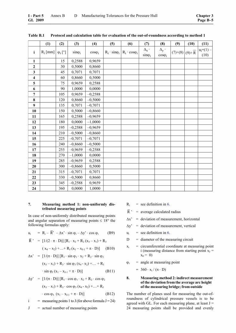
Table B.1 Protocol and calculation table for evaluation of the out-of-roundness according to method 1
(1) (2) (3) (4) (5) (6) (7) (8) (9) (10) (11)
i Ri [mm] ϕi [°] sinϕi cosϕi Ri · sinϕi Ri · cosϕiΔx · sinϕi
Δy · cosϕi
(7)+(8) (9)+ R ui=(1) –
(10) 1 15 0,2588 0,9659 2 30 0,5000 0,8660 3 45 0,7071 0,7071 4 60 0,8660 0,5000 5 75 0,9659 0,2588 6 90 1,0000 0,0000 7 105 0,9659 –0,2588 8 120 0,8660 –0,5000 9 135 0,7071 –0,7071
10 150 0,5000 –0,8660 11 165 0,2588 –0,9659 12 180 0,0000 –1,0000 13 195 –0,2588 –0,9659 14 210 –0,5000 –0,8660 15 225 –0,7071 –0,7071 16 240 –0,8660 –0,5000 17 255 –0,9659 –0,2588 18 270 –1,0000 0,0000 19 285 –0,9659 0,2588 20 300 –0,8660 0,5000 21 315 –0,7071 0,7071 22 330 –0,5000 0,8660 23 345 –0,2588 0,9659 24 360 0,0000 1,0000
7. Measuring method 1: non-uniformly dis-tributed measuring points
In case of non-uniformly distributed measuring points and angular separation of measuring points ≤ 18° the following formulas apply:
ui = Ri – R′ – Δx’ ⋅ sin ϕi – Δy’ ⋅ cos ϕi (B9)
R ’ = [1/(2 ⋅ π ⋅ D)] [R1 ⋅ x2 + R2 (x3 – x1) + R3
( x4 – x2) +…+ RJ (x1 – xJ-1 + π ⋅ D)] (B10)
Δx’ = [1/(π ⋅ D)] [R1 ⋅ sin ϕ1 ⋅ x2 + R2 ⋅ sin ϕ2
(x3 – x1) + R3 ⋅ sin ϕ3 (x4 - x2) +… + RJ
· sin φJ (x1 – xJ-1 + π ⋅ D)] (B11)
Δy’ = [1/(π ⋅ D)] [R1 ⋅ cos ϕ1 ⋅ x2 + R2 ⋅ cos ϕ2
(x3 – x1) + R3 ⋅ cos ϕ3 (x4 - x2) +…+ RJ
⋅ cos ϕJ (x1 – xJ-1 + π ⋅ D)] (B12)
i = measuring points 1 to J (for above formula J = 24)
J = actual number of measuring points
Ri = see definition in 6.
R ’ = average calculated radius
Δx’ = deviation of measurement, horizontal
Δy’ = deviation of measurement, vertical
ui = see definition in 6.
D = diameter of the measuring circuit
xi = circumferential coordinate at measuring point i (measuring distance from starting point xJ = x0 = 0)
ϕi = angle at measuring point
= 360 ⋅ xi / (π ⋅ D)
8. Measuring method 2: indirect measurement of the deviation from the average arc height of the measuring bridge; from outside
The number of planes used for measuring the out-of-roundness of cylindrical pressure vessels is to be agreed with GL. For each measuring plane, at least J = 24 measuring points shall be provided and evenly
I - Part 5 GL 2009
Annex B Manufacturing Tolerances for the Pressure Hull Chapter 3Page B–5
D
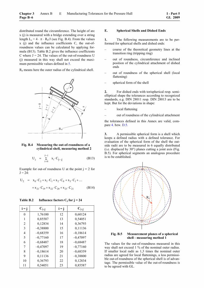
distributed round the circumference. The height of arc x (j) is measured with a bridge extending over a string length Ls = 4 ⋅ π ⋅ R0/J (see Fig. B.4). From the values x (j) and the influence coefficients C, the out-of-roundness values can be calculated by applying for-mula (B13). Table B.2 gives the influence coefficients C where J = 24. The values of the out-of-roundness U (j) measured in this way shall not exceed the maxi-mum permissible values defined in 5.
R0 means here the outer radius of the cylindrical shell.
�
�
.�
�,
/����
/����
/���
Fig. B.4 Measuring the out-of-roundness of a cylindrical shell, measuring method 2
J 1
j i i ji 0
U x C−
−=
= ⋅Σ (B13)
Example for out-of roundness U at the point j = 2 for J = 24:
2 0 2 1 1 2 0 3 1U x C x C x C x C ....= ⋅ + ⋅ + ⋅ + ⋅ +
21 19 22 20 23 21x C x C x C+ ⋅ + ⋅ + ⋅ (B14)
Table B.2 Influence factors Ci for j = 24
i = j C|i-j| i = j C|i-j|
0 1 2 3 4 5 6 7 8 9
10 11
1,76100 0,85587 0,12834
–0,38800 –0,68359 –0,77160 –0,68487 –0,47097 –0,18614
0,11136 0,36793 0,54051
12 13 14 15 16 17 18 19 20 21 22 23
0,60124 0,54051 0,36793 0,11136
–0,18614 –0,47097 –0,68487 –0,77160 –0,68359 –0,38800
0,12834 0,85587
E. Spherical Shells and Dished Ends
1. The following measurements are to be per-formed for spherical shells and dished ends:
– course of the theoretical geometry lines at the transition ring (tripping ring)
– out of roundness, circumference and inclined position of the cylindrical attachment of dished ends
– out of roundness of the spherical shell (local flattening)
– spherical form of the shell
2. For dished ends with torispherical resp. semi-elliptical shape the tolerances according to recognized standards, e.g. DIN 28011 resp. DIN 28013 are to be kept. But for the deviations in shape:
– local flattening
– out of roundness of the cylindrical attachment
the tolerances defined in this Annex are valid, com-pare 4. bzw. D.5.
3. A permissible spherical form is a shell which keeps a defined radius with a defined tolerance. For evaluation of the spherical form of the shell the out-side radii are to be measured in 6 equally distributed (i.e. displaced by 30°) planes cutting a joint axis (Fig. B.5). For spherical segments an analogous procedure is to be established.
Fig. B.5 Measurement planes of a spherical
shell - measuring method 1
The values for the out-of-roundness measured in this way shall not exceed 1 % of the nominal outer radius. If smaller local radii as 1,3 times the nominal outer radius are agreed for local flattenings, a less permissi-ble out-of-roundness of the spherical shell is of advan-tage. The permissible value of the out-of-roundness is to be agreed with GL.
Ri
Chapter 3 Page B–6
Annex B Manufacturing Tolerances for the Pressure Hull I - Part 5GL 2009
E
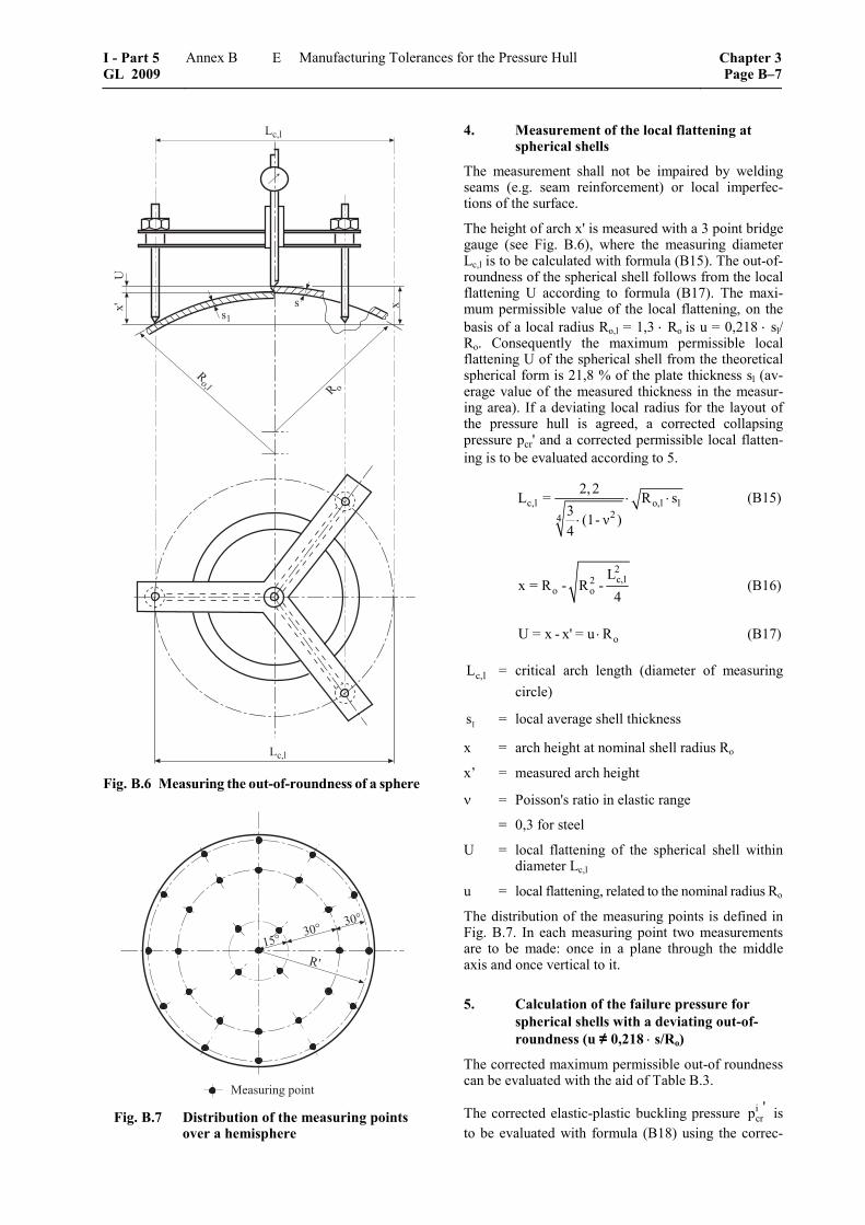
.�0�
�
1�2
��
�,0� � ,
�
.�0� Fig. B.6 Measuring the out-of-roundness of a sphere
�2
������
���
����)���'��,��� Fig. B.7 Distribution of the measuring points
over a hemisphere
4. Measurement of the local flattening at spherical shells
The measurement shall not be impaired by welding seams (e.g. seam reinforcement) or local imperfec-tions of the surface.
The height of arch x' is measured with a 3 point bridge gauge (see Fig. B.6), where the measuring diameter Lc,l is to be calculated with formula (B15). The out-of-roundness of the spherical shell follows from the local flattening U according to formula (B17). The maxi-mum permissible value of the local flattening, on the basis of a local radius Ro,l = 1,3 ⋅ Ro is u = 0,218 ⋅ sl/ Ro. Consequently the maximum permissible local flattening U of the spherical shell from the theoretical spherical form is 21,8 % of the plate thickness sl (av-erage value of the measured thickness in the measur-ing area). If a deviating local radius for the layout of the pressure hull is agreed, a corrected collapsing pressure pcr' and a corrected permissible local flatten-ing is to be evaluated according to 5.
c,l o,l l24
2,2L = R s3 (1- ν )4
⋅ ⋅⋅
(B15)
2c,l2
o oL
x = R - R -4
(B16)
oU = x - x' = u R⋅ (B17)
c,lL = critical arch length (diameter of measuring circle)
ls = local average shell thickness
x = arch height at nominal shell radius Ro
x’ = measured arch height
ν = Poisson's ratio in elastic range
= 0,3 for steel
U = local flattening of the spherical shell within diameter Lc,l
u = local flattening, related to the nominal radius Ro
The distribution of the measuring points is defined in Fig. B.7. In each measuring point two measurements are to be made: once in a plane through the middle axis and once vertical to it.
5. Calculation of the failure pressure for spherical shells with a deviating out-of-roundness (u ≠ 0,218 ⋅ s/Ro)
The corrected maximum permissible out-of roundness can be evaluated with the aid of Table B.3.
The corrected elastic-plastic buckling pressure icr
'p is to be evaluated with formula (B18) using the correc-
I - Part 5 GL 2009
Annex B Manufacturing Tolerances for the Pressure Hull Chapter 3Page B–7
E
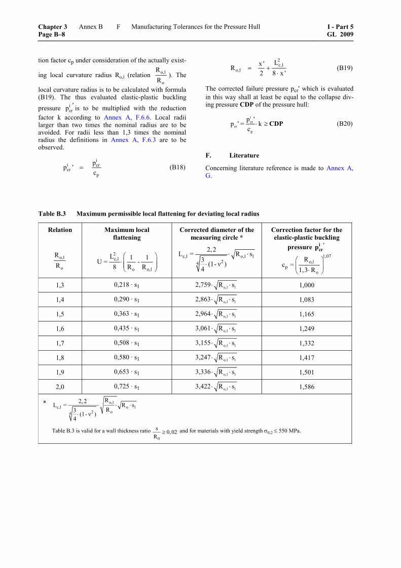
tion factor cp under consideration of the actually exist-
ing local curvature radius Ro,l (relation o,l
o
RR
). The
local curvature radius is to be calculated with formula (B19). The thus evaluated elastic-plastic buckling pressure i
cr'p is to be multiplied with the reduction
factor k according to Annex A, F.6.6. Local radii larger than two times the nominal radius are to be avoided. For radii less than 1,3 times the nominal radius the definitions in Annex A, F.6.3 are to be observed.
i
i crcr
p
pp '
c= (B18)
2c,l
o,lLx 'R
2 8 x '= +
⋅ (B19)
The corrected failure pressure pcr' which is evaluated in this way shall at least be equal to the collapse div-ing pressure CDP of the pressure hull:
icr
crp
p 'p ' = k
c⋅ ≥ CDP (B20)
F. Literature
Concerning literature reference is made to Annex A, G.
Table B.3 Maximum permissible local flattening for deviating local radius
Relation
o,l
o
RR
Maximum local flattening
2c,l
o o,l
L 1 1U = -8 R R
⎛ ⎞⋅ ⎜ ⎟⎜ ⎟⎝ ⎠
Corrected diameter of the measuring circle *
c,l o,l l24
2,2L = R s3 (1- ν )4
⋅ ⋅⋅
Correction factor for the elastic-plastic buckling
pressure i 'crp
1,07o,l
po
Rc =
1,3 R⎛ ⎞⎜ ⎟⋅⎝ ⎠
1,3 0,218 · s1 2,759 o,l lR s⋅ ⋅ 1,000
1,4 0,290 · s1 2,863 o,l lR s⋅ ⋅ 1,083
1,5 0,363 · s1 2,964 o,l lR s⋅ ⋅ 1,165
1,6 0,435 · s1 3,061 o,l lR s⋅ ⋅ 1,249
1,7 0,508 · s1 3,155 o,l lR s⋅ ⋅ 1,332
1,8 0,580 · s1 3,247 o,l lR s⋅ ⋅ 1,417
1,9 0,653 · s1 3,336 o,l lR s⋅ ⋅ 1,501
2,0 0,725 · s1 3,422 o,l lR s⋅ ⋅ 1,586
* o,lc,l o l
o24
R2,2L = R sR3 (1- ν )
4
⋅ ⋅ ⋅⋅
Table B.3 is valid for a wall thickness ratio 0
s 0,02R
≥ and for materials with yield strength σ0,2 ≤ 550 MPa.
Chapter 3 Page B–8
Annex B Manufacturing Tolerances for the Pressure Hull I - Part 5GL 2009
F
Annex C
Acrylic Windows
A. General
1. Scope
In the sense of these Rules, acrylic windows are flat or curved windows for the view ports of pressure hulls which are made of cast, unlaminated polymethyl methacrylate plastic.
2. Limits of application
For acrylic windows following limits for application apply:
– designed service life 10 resp. 20 years (see explanatory notes below)
– temperature range –18 °C to +66 °C
– rate of pressurization max. 10 bar/s
– pressure cycles at design pressure max. 10.000
– period under pressure at design pressure max. 40.000 h
– maximum allowable working pressure max. 1380 bar
The design service life for acrylic windows depends on numerous factors, in particular on the kind of load-ing. The maximum design service life to be assumed for spherical or cylindrical windows subjected to ex-ternal overpressure, which are exclusively exposed to compressive stresses or minor bending stresses only, is generally 20 years, while for flat windows with flat seat it is 10 years. The design service life starts with the date of manufacturing regardless of the use in the submersible.
Depending on the previous actual loads acting on the windows and testing to be agreed with GL in detail, extension of the service life of acrylic windows may be approved.
3. Permissions/Approvals
For the design and manufacturing of acrylic windows the following permissions/approvals are required:
– approval of drawings and of the design for each type of window and each form of application by GL
– approval as material manufacturer by GL
– Manufacturer Inspection Certificate for the material, compare B.3.
– approval by GL as manufacturer of acrylic win-dows
– GL Certificate which certifies the manufacturing inspections and the pressure tests according to C.6.
B. Materials
1. Materials for acrylic windows are to be manufactured in accordance with a recognized stan-dard (e.g. ANSI/ASME PVHO 1, Section 2). The producer is required to certify this before manufacture commences.
2. Acrylic windows have to meet the minimum physical requirements stated in Table C.1.
3. For each batch of acrylic plastic processed to windows the manufacturer has to issue a Manufacturer Inspection Certificate containing at least the following details:
– number and date of Certificate
– manufacturer's name and address
– designation and application of casting type
– batch number, quantity, shape and size of cast-ings
– marking of castings
– results of tests applied in accordance with Table C.1
– stamp and signature
4. Where a Manufacturer Inspection Certificate of the kind required is not available for the acrylic plastic or where the conditions for recognition of the Inspection Certificate are not satisfied, the tests are to be extended in a manner to be agreed with GL in each individual case.
5. Each casting is to be provided at one point at least with a marking which identifies the type of cast-ing, the batch number, the date of manufacture and the name of the manufacturer.
I - Part 5 GL 2009
Annex C Acrylic Windows Chapter 3Page C–1
B
C. Manufacture of Windows
1. The manufacture of acrylic windows covered by these Rules may only take place in specialized workshops which have been approved by GL for that purpose. Such approval can be granted only to those companies which employ properly trained specialists and which have available the necessary technical facilities enabling them to undertake the expert form-ing, machining, heat treatment and quality control of acrylic windows.
Application for approval is to be made to GL before the manufacture of windows commences.
2. The acrylic plastic to be used has to meet the requirements stated in B. After machining and any necessary forming operations, each window is to be subjected to heat treatment (tempering) in accordance with the acrylic plastic manufacturer's specification. After tempering no further mechanical polishing may be carried out on the window.
Flat disk windows for diving chambers where only the surrounding area is professionally machined need not to undergo a heat treatment after manufacturing.
3. Window surfaces are to be polished in such a way as to meet the optical clarity requirement stated in Table C.1.
4. For each window or series of windows the window manufacturer has to issue a component Cer-tificate specifying all the stages of manufacture such as cutting, sticking, polishing, forming and tempering. In addition the tests carried out, the test results, the marking of the windows and the date of manufacture are to be indicated.
5. Each window is to be permanently marked with at least the following details:
– design pressure PR = NDP [bar]
– design temperature [°C]
– GL approval stamp
– manufacturer's name or identifying mark
– serial number and year of manufacture.
– direction of pressure, if it is not clear
Wherever possible, the marking is to be engraved in the non-load-bearing portion of the window edge. The use of punches is not allowed.
6. Acrylic windows are to be presented to GL for an inspection of manufacture. In addition, each window is to be subjected, in the presence of a GL Surveyor, to a pressure test in accordance with GL Rules for Manned Submersibles (I-5-2), Section 2, F.3.3. At the pressure test the direction of pressure has to be ob-served. If the windows are subjected to pressure from both sides, this is to be considered for the testing.
D. Window Shapes and Sizes
1. The standard shapes and sizes shown in Table C.2, C.3 and C.4 are to be selected for the acrylic windows. For design pressure PR in general the nomi-nal diving pressure NDP is to be used, see also the Rules for Manned Submersibles (I-5-2), Table 4.2 resp. Unmanned Submersibles (ROV, AUV) and Un-derwater Working Machines (I-5-3), Table 3.2.
2. Acrylic windows of other shapes and sizes or for other ranges of pressure may be used on applica-tion if approved by GL or if they are designed and manufactured to a standard recognized by GL.
Acrylic windows may be performed e.g. according to ASME PVHO-1, Section 2.
3. The design temperature to be assumed for acrylic windows shall be the mean value of the maxi-mum external and internal temperatures to be expected under design pressure conditions.
4. Windows subjected to pressure from both sides are to be designed for the maximum pressure applied, regardless of whether this pressure is external or internal.
5. Pressure may only be applied to the convex side of spherical shell windows.
6. The thickness of the window has to be eve-rywhere equal to, or greater than, the minimum value determined by reference to Tables C.2, C.3 and C.4. For intermediate temperatures linear interpolation may be applied.
7. With flat windows having right-angled edge and an O-ring seal, the outside diameter of the disk shall be within + 0,00/–0,25 mm of the nominal value, or within + 0,00/–0,75 mm where flat gasket seals are used.
8. Because of stress increasing effects grooves for seals shall not be located in the acrylic window bearing surface and also not in the window itself.
9. The greater diameter of the conical bearing surface of an acrylic window shall be within +0,000/–0,002 Do of the nominal value.
The included conical angle of the window shall be within + 0,25/–0,00 degrees of the nominal value.
10. The concave or convex surface of the window shall not differ from an ideal spherical sector by more than ± 0,5 % of the nominal external spherical radius.
11. The surface roughness Ra of the window bearing surface shall be 0,75 μm or better.
Chapter 3 Page C–2
Annex C Acrylic Windows I - Part 5GL 2009
D
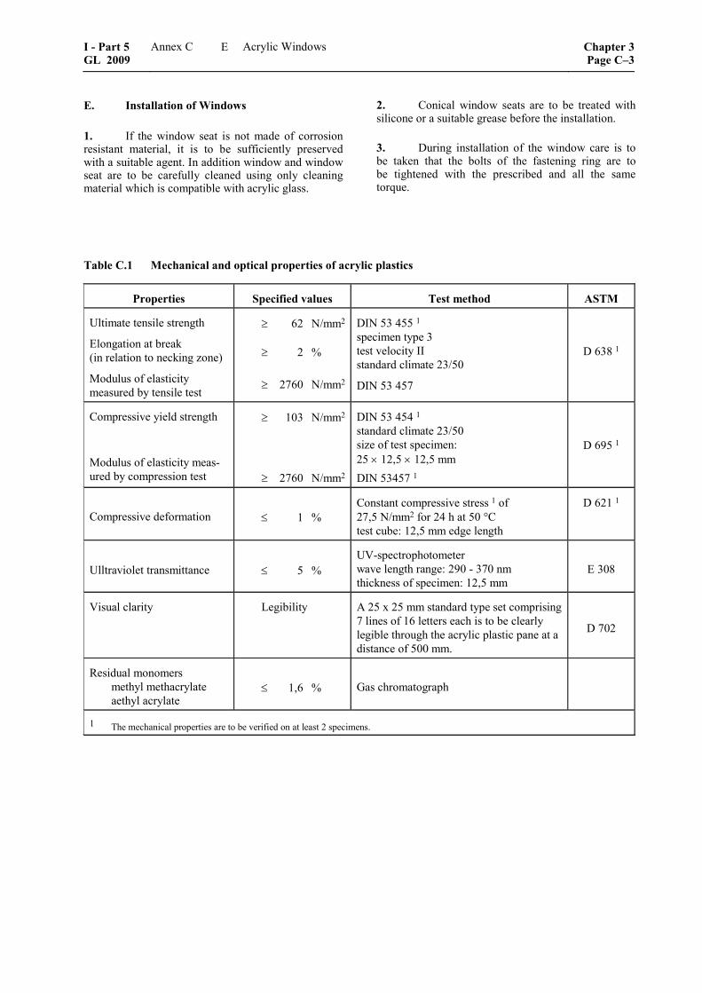
E. Installation of Windows
1. If the window seat is not made of corrosion resistant material, it is to be sufficiently preserved with a suitable agent. In addition window and window seat are to be carefully cleaned using only cleaning material which is compatible with acrylic glass.
2. Conical window seats are to be treated with silicone or a suitable grease before the installation.
3. During installation of the window care is to be taken that the bolts of the fastening ring are to be tightened with the prescribed and all the same torque.
Table C.1 Mechanical and optical properties of acrylic plastics
Properties Specified values Test method ASTM
Ultimate tensile strength
Elongation at break (in relation to necking zone)
Modulus of elasticity measured by tensile test
≥ 62 N/mm2
≥ 2 %
≥ 2760 N/mm2
DIN 53 455 1 specimen type 3 test velocity II standard climate 23/50
DIN 53 457
D 638 1
Compressive yield strength
Modulus of elasticity meas-ured by compression test
≥ 103 N/mm2
≥ 2760 N/mm2
DIN 53 454 1 standard climate 23/50 size of test specimen: 25 × 12,5 × 12,5 mm DIN 53457 1
D 695 1
Compressive deformation ≤ 1 % Constant compressive stress 1 of 27,5 N/mm2 for 24 h at 50 °C test cube: 12,5 mm edge length
D 621 1
Ulltraviolet transmittance ≤ 5 % UV-spectrophotometer wave length range: 290 - 370 nm thickness of specimen: 12,5 mm
E 308
Visual clarity Legibility A 25 x 25 mm standard type set comprising 7 lines of 16 letters each is to be clearly legible through the acrylic plastic pane at a distance of 500 mm.
D 702
Residual monomers methyl methacrylate aethyl acrylate
≤ 1,6 % Gas chromatograph
1 The mechanical properties are to be verified on at least 2 specimens.
I - Part 5 GL 2009
Annex C Acrylic Windows Chapter 3Page C–3
E
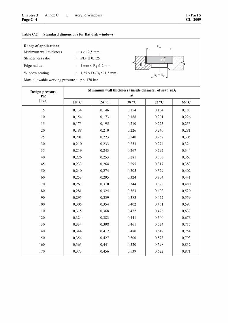
Table C.2 Standard dimensions for flat disk windows
Range of application: Minimum wall thickness : s ≥ 12,5 mm Slenderness ratio : s/Do ≥ 0,125
Edge radius : 1 mm ≤ R1 ≤ 2 mm
Window seating : 1,25 ≤ Do/Df ≤ 1,5 mm
Max. allowable working pressure : p ≤ 170 bar �������
��
�
Minimum wall thickness / inside diameter of seat s/Di at
Design pressure PR
[bar] 10 °C 24 °C 38 °C 52 °C 66 °C
5
10
15
20
25
30
35
40
45
50
60
70
80
90
100
110
120
130
140
150
160
170
0,134
0,154
0,173
0,188
0,201
0,210
0,219
0,226
0,233
0,240
0,253
0,267
0,281
0,295
0,305
0,315
0,324
0,334
0,344
0,354
0,363
0,373
0,146
0,173
0,195
0,210
0,223
0,233
0,243
0,253
0,264
0,274
0,295
0,310
0,324
0,339
0,354
0,368
0,383
0,398
0,412
0,427
0,441
0,456
0,154
0,188
0,210
0,226
0,240
0,253
0,267
0,281
0,295
0,305
0,324
0,344
0,363
0,383
0,402
0,422
0,441
0,461
0,480
0,500
0,520
0,539
0,164
0,201
0,223
0,240
0,257
0,274
0,292
0,305
0,317
0,329
0,354
0,378
0,402
0,427
0,451
0,476
0,500
0,524
0,549
0,573
0,598
0,622
0,188
0,226
0,253
0,281
0,305
0,324
0,344
0,363
0,383
0,402
0,441
0,480
0,520
0,559
0,598
0,637
0,676
0,715
0,754
0,793
0,832
0,871
Chapter 3 Page C–4
Annex C Acrylic Windows I - Part 5GL 2009
E

Table C.3 Standard dimensions for spherical shell windows with conical seat (opening angle 60° / 90°)
Range of application: Opening angle : α ≥ 60° Minimum wall thickness : s ≥ 12,5 mm Minimum values for s/Ri :
α 60° ≤ α < 90° 90° ≤ α < 120° s/Ri 0,09 0,06
Window seating : Di/Df ≥ 1,02 Max. allowable working pressure : p ≤ 170 bar
�
��
��
��
Minimum wall thickness / inside diameter of seat s/Di
for 60° ≤ α < 90° at
Minimum wall thickness / inside diameter of seat s/Di
for 90° ≤ α < 120° at
Design pressure
PR [bar] 10 °C 24 °C 38 °C 52 °C 66 °C
Design pressure
PR [bar] 10 °C 24 °C 38 °C 52 °C 66 °C
5
10
15
20
25
30
35
40
45
50
60
70
80
90
100
110
120
130
140
150
160
170
0,090
0,090
0,090
0,090
0,090
0,097
0,104
0,112
0,119
0,126
0,140
0,153
0,166
0,179
0,191
0,203
0,215
0,227
0,238
0,248
0,259
0,269
0,090
0,090
0,090
0,097
0,108
0,119
0,129
0,140
0,150
0,160
0,179
0,197
0,215
0,232
0,248
0,264
0,279
0,293
0,307
0,320
0,332
0,344
0,090
0090
0,097
0,112
0,126
0,140
0,153
0,166
0,179
0,191
0,215
0,238
0,259
0,279
0,298
0,315
0,332
0,348
0,363
0,377
0,391
0,404
0,090
0,090
0,108
0,126
0,143
0,160
0,176
0,191
0,206
0,221
0,248
0,274
0,298
0,320
0,340
0,359
0,377
0,394
0,410
0,425
0,439
0,452
0,090
0,112
0,140
0,166
0,191
0,215
0,238
0,259
0,279
0,298
0,332
0,363
0,391
0,416
0,439
0,460
0,480
5
10
15
20
25
30
35
40
45
50
60
70
80
90
100
110
120
130
140
150
160
170
0,042
0,042
0,043
0,049
0,054
0,060
0,065
0,070
0,075
0,080
0,089
0,098
0,107
0,116
0,124
0,133
0,142
0,151
0,160
0,168
0,177
0,185
0,042
0,043
0,052
0,060
0,067
0,075
0,082
0,089
0,095
0,102
0,116
0,128
0,142
0,155
0,168
0,181
0,194
0,206
0,218
0,230
0,242
0,254
0,042
0,049
0,060
0,070
0,080
0,089
0,098
0,107
0,116
0,124
0,142
0,160
0,177
0,194
0,210
0,226
0,242
0,257
0,272
0,287
0,300
0,314
0,042
0,054
0,067
0,080
0,091
0,102
0,113
0,124
0,135
0,146
0,168
0,190
0,210
0,230
0,250
0,269
0,287
0,304
0,320
0,336
0,351
0,365
0,049
0,070
0,089
0,107
0,124
0,142
0,160
0,177
0,194
0,210
0,242
0,272
0,300
0,327
0,351
0,373
0,393
0,411
I - Part 5 GL 2009
Annex C Acrylic Windows Chapter 3Page C–5
E
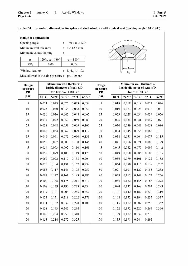
Table C.4 Standard dimensions for spherical shell windows with conical seat (opening angle 120°/ 180°)
Range of application: Opening angle : 180 ≥ α ≥ 120° Minimum wall thickness : s ≥ 12,5 mm Minimum values for s/Ri :
α 120° ≤ α < 180° α = 180° s/Ri 0,06 0,03
Window seating : Di/Df ≥ 1,02 Max. allowable working pressure : p ≤ 170 bar
�
��
��
��
Minimum wall thickness / Inside diameter of seat s/Di
for 120° ≤ α < 180° at
Minimum wall thickness / Inside diameter of seat s/Di
for α = 180° at
Design pressure
PR [bar] 10 °C 24 °C 38 °C 52 °C 66 °C
Design pressure
PR [bar] 10 °C 24 °C 38 °C 52 °C 66 °C
5
10
15
20
25
30
35
40
45
50
60
70
80
90
100
110
120
130
140
150
160
170
0,021
0,025
0,030
0,034
0,038
0,042
0,046
0,050
0,054
0,059
0,067
0,075
0,083
0,092
0,100
0,108
0,117
0,123
0,131
0,138
0,146
0,153
0,023
0,030
0,036
0,042
0,048
0,054
0,061
0,067
0,073
0,079
0,092
0,104
0,117
0,127
0,138
0,149
0,161
0,171
0,182
0,193
0,204
0,214
0,025
0,034
0,042
0,050
0,059
0,067
0,075
0,083
0,092
0,100
0,117
0,131
0,146
0,161
0,175
0,190
0,204
0,218
0,232
0,245
0,259
0,272
0,028
0,038
0,048
0,059
0,069
0,079
0,090
0,100
0,110
0,119
0,138
0,157
0,175
0,193
0,211
0,228
0,245
0,262
0,278
0,294
0,310
0,325
0,034
0,050
0,067
0,083
0,100
0,117
0,131
0,146
0,161
0,175
0,204
0,232
0,259
0,285
0,310
0,334
0,357
0,379
0,400
5
10
15
20
25
30
35
40
45
50
60
70
80
90
100
110
120
130
140
150
160
170
0,018
0,019
0,023
0,026
0,030
0,034
0,038
0,041
0,045
0,049
0,056
0,064
0,071
0,079
0,086
0,094
0,101
0,108
0,115
0,122
0,129
0,135
0,018
0,023
0,028
0,034
0,039
0,045
0,051
0,056
0,062
0,068
0,079
0,090
0,101
0,112
0,122
0,132
0,142
0,152
0,162
0,172
0,182
0,191
0,019
0,026
0,034
0,041
0,049
0,056
0,064
0,071
0,079
0,086
0,101
0,115
0,129
0,142
0,155
0,168
0,182
0,194
0,207
0,220
0,232
0,244
0,021
0,030
0,039
0,049
0,058
0,068
0,077
0,086
0,096
0,105
0,122
0,139
0,155
0,172
0,188
0,204
0,220
0,235
0,250
0,264
0,278
0,292
0,026
0,041
0,056
0,071
0,086
0,101
0,115
0,129
0,142
0,155
0,182
0,207
0,232
0,256
0,278
0,299
0,319
0,337
0,352
0,366
Chapter 3 Page C–6
Annex C Acrylic Windows I - Part 5GL 2009
E
Annex D
Manufacture and Treatment of Fibre Reinforced Plastics (FRP)
A. General
1. Definition
Fibre reinforced plastics are heterogeneous materials, consisting of a thermosetting resin as the matrix and an embedded fibrous reinforcing material.
2. Scope of application
For submersibles plastics are mainly used for the fol-lowing components:
– exostructure
– rudder and propeller
– pressure vessels
B. Requirements for the Materials and their Processing
1. Materials
1.1 Approval
1.1.1 The materials used for the manufacturing of components from FRP shall be assessed and approved by GL.
1.1.2 The approval refers only to the approved material. The applicability of this material in connec-tion with other materials shall be demonstrated inde-pendently by the manufacturer or the user in a suitable manner.
1.2 Quality assurance
1.2.1 A constant material quality shall be secured by the manufacturer through constant quality assur-ance measures.
1.2.2 GL reserve the right to demand resp. carry out spot tests of the material properties during the duration of the material approval.
1.3 Types of materials
For the construction of submersibles in general the following materials are to be considered:
– laminated resins, e.g. cold-setting or hot-setting unsaturated polyester (UP) resins and cold set-ting epoxy (EP) resins
– reinforcing materials, e.g. fibre reinforcements made of glass and carbon
– prepregs as reinforcing materials, which are pre-impregnated with a thermosetting resin and which can be processed without any further ad-dition of resin or hardener
– core materials, e.g. rigid foams with adequate compressive strength
– adhesives, e.g. cold- and hot-setting thermoset-ting adhesives and hot-melt adhesives
– flame retardant laminates produced by additives to the resin system, whereby the viscosity of the resin or the mechanical properties of the manu-factured laminates not be changed essentially
Other materials may be approved in agreement with GL Head Office.
2. Manufacturing
2.1 Approval
2.1.1 Manufacture of FRP-components shall only be performed by workshops which are approved by GL for the manufacture of components made from fibre-reinforced thermosetting resins.
2.1.2 The manufacture of FRP-components shall only be carried out by persons with professional knowledge. This professional knowledge shall in general be verified by certificates of the corresponding training courses.
2.1.3 All manufacturing facilities, store-rooms and their operational equipment shall fulfil the require-ments of the responsible authorities. The manufacturer is alone responsible for compliance with these re-quirements.
2.2 Store rooms and laminating workshops
The danger of contamination of laminating materials is to be minimized through separation of production facilities from store rooms.
2.3 Guidelines for processing
2.3.1 As a matter of principle, only materials ap-proved by GL shall be used. In addition to the choice of suitable and approved materials, special care shall be taken when working with them because of the great influence on the properties of the product.
I - Part 5 GL 2009
Annex D Manufacture and Treatment of Fibre Reinforced Plastics (FRP) Chapter 3Page D–1
B
2.3.2 For the preparation and processing of the resin compounds and reinforcing material, beside the GL Rules, the instructions issued by the material manufacturers and the regulations of the competent authorities are to be observed.
2.4 Manufacturing surveillance
For components made of FRP, manufacturing surveil-lance has to consist of the quality control of the basic materials, production surveillance and the quality inspection of the finished components.
2.5 Repair of components
2.5.1 Repairs of structural FRP-components shall only be performed by workshops which are approved by GL.
2.5.2 For the approval of a repair, all design and re-pair drawings needed to assess the repair of the relevant components are to be submitted to GL. The repair plan is to be examined by GL Head Office and approved.
2.5.3 A report is to be established for each repair which has to be signed by the head of the repair team.
2.5.4 If the materials and laminates used for the repair are not identical to those employed when the component was manufactured, equivalence of the combination of materials shall be verified with respect to their properties.
3. Detailed requirements
The detailed requirements for the areas pointed out are defined in the GL Rules for Fibre Reinforced Plastics and Bonding (II-2-1).
C. Requirements for the Design
1. Design data
The mechanical properties and the nominal thickness of the laminate as well as weight, type and portion of the reinforcement layers, which can be individually used, are to be defined on the design drawings.
2. Design measures
For the design of components the following measures are to be considered:
2.1 Changes in the laminate thickness are to be established with a smooth transition of 25 mm per 600 g/m². In the transition area from a sandwich design to massive laminate the core material is to be gradually tapered (at least 3 : 1).
2.2 In general frame and stiffening sections are to be built up by layer and layer on the laminate, as far as the last layer is not yet cured. Where internal struc-
tural members are crossing each other, special care is to be taken that the load-bearing capacity remains unchanged.
2.3 Closed hollow spaces in the structure which may be subjected to external pressure are to be avoided.
2.4 If core materials are used in areas which may be subjected to external pressure, pressure-proof mate-rials like e.g. rigid foams are to be used.
2.5 Stress concentrations, peaks in stiffness and discontinuities are to be avoided. It has to be ensured, that because of cut-outs, openings in load carrying elements and the connection of fittings the strength of the component is not impaired.
2.6 If various components which have been pro-duced in different moulds are to be connected with each other, then the connecting laminates have to be finished before curing of the components.
If components of FRP are bolted which each other or with components of other materials, the connecting elements (bolts, nuts, washers) are to be of seawater resistant material. Bolted connections are to be dimen-sioned according to the occurring forces.
2.7 In areas with local force introduction (e.g. connecting elements of the exostructure, bitts, cleats) sole pieces and/or shims of adequate strength are to be situated. The strength, e.g. bearing strength is to be proven in a suitable way. The connecting area of these sole pieces is to be prepared in a suitable way and shall be free of contamination.
2.8 Metallic materials used in the design, like e.g. steel or aluminium alloys have to be suitable for the intended purpose and shall not impair the curing of the laminating resins.
Local reinforcements of metallic materials are to be cleaned and degreased carefully and, if possible, are to be shot blasted or roughened up to achieve a toothing effect.
2.9 For sandwich laminates in way of bolted connections and fittings, inserts of a material, which can withstand the compression and the design loads, are to be provided. The inserts are to be connected with the core material and the laminate layers in the best way.
2.10 Laminate edges and holes are to be sealed.
2.11 Further design measures which are recom-mendable for different shipbuilding components made of plastics are contained in the GL Rules for Yachts ≥ 24 m (I-3-2), Section 2, E. and Yachts and Boats up to 24 m (I-3-3), Section 1, B. and C.
Chapter 3 Page D–2
Annex D Manufacture and Treatment of Fibre Reinforced Plastics (FRP) I - Part 5GL 2009
C
Annex E
Basic Requirements for Umbilicals
A. General
1. Definition
The umbilical is regarded as the connecting link be-tween support ship and an element under water, which may include hose assemblies for liquid and gas trans-port and monitoring, communication, data transfer and energy supply cables as well eventually a lifting cable.
This bundled or integrated supply line may also be used between elements under water.
As elements under water in the sense of this Annex are to be regarded e.g.:
– diving chambers
– non-autonomous (manned) and remotely con-trolled (unmanned) submersibles
– launchers
– underwater working machines
– diving equipment
The integrated or also independent lifting cable serves for launching and recovery, as well as for lifting and lowering of an element under water as well as for absorption of tension loads during operation. The lifting cable may also be designed as bearing element, e.g. as netting within the sheathing of the umbilical.
2. Scope
This Annex is valid for the technical requirements and the testing of umbilicals including connecting pieces as well as shut-off devices at the ends and the load transfer points. The load transfer points of the support ship/element are not subject of this Annex.
Furtheron this Annex is valid for cables and hose as-semblies which may be subjected to external overpres-sure and integrated lifting cables.
The penetration into the pressure hull or a vessel under pressure is part of the element.
Some basic requirements for the coil-up/coil-off mechanism are defined.
The supply systems for the materials, data and ener-gies transferred by the umbilical form part of the sup-port ship or element and are not treated in this Annex.
Umbilical systems for production duties, as e.g. used in the oil and gas industry, are primarily not subject of this Annex.
3. Quality Management System
The manufacturer of umbilicals has to apply a recog-nized quality management system, like e.g. ISO 9001 or equivalent. This system has to cover design, manu-facture and testing.
4. Equivalence
Umbilicals deviating from this Annex in their type, structure and the compliance with some detailed re-quirements may be accepted by GL, provided that they are found to be equivalent to the principle require-ments defined in this Annex.
B. Principles for Layout and Design
1. General
1.1 The requirements defined in the following are minimum requirements for the majority of the pro-spective applications. For special use the selection of the requirements is to be agreed with GL.
1.2 Generally the following requirements are to be considered for the design:
– environmental influences, see the GL Rules for Manned Submersibles (I-5-2), Section 2, D.
– influence of weight (deadweight, empty, full)
– buoyancy behaviour (positive and negative buoyancy, neutral buoyancy)
– dynamic influences because of ship movements and increasing and lowering the pressure inside
– thermal influences on expansion and shrinking because of possible temperature changes inside and outside
– thermal influences because of power cables partly on drum
– pressure differences in hoses between upper and lower end of umbilical
– chemical and electrochemical influences
1.3 The control of the coil-up/coil-off mechanism for the umbilical and the monitoring of the supply flow through the umbilical including the production of materials to be supplied are to be concentrated at a central position.
I - Part 5 GL 2009
Annex E Basic Requirements for Umbilicals Chapter 3Page E–1
B
For manned, non-autonomous submersibles the con-trol and monitoring is to be integrated into the control stand which maintains the connection with the sub-mersible. For unmanned, remotely controlled sub-mersibles and other elements these are to be integrated into the control station.
1.4 Umbilicals shall be produced in one piece for the complete required length and shall not be divided into different parts.
1.5 Requirements and tests of umbilicals for hose supplied diving equipment are to be taken from stan-dard EN 15333-1.
2. Mechanical requirements
2.1 Materials
Only materials according to generally recognized standards are to be used and their application has to be clearly recorded and traced.
The materials are to be suitable for the use in salt water. If a mission in other media than water is planned, these are to be adequately considered.
The material of hose assemblies is to be suitable for the media to be transported.
The materials are to be suitable for permanent and varying bending stress.
If hoses are used for breathing gases their suitability is to be proven (e.g. off-gassing test).
Umbilicals, hose assemblies and cables are to be pro-tected against abrasion and damages.
For the protection cover of umbilicals attention is to be given that no internal pressure can be built up if little leakages occur in the hose. Metal inserts in the protection cover are to be avoided.
2.2 Tensile load
2.2.1 For umbilicals with integrated lifting cable the mechanical characteristics are to be judged accord-ing to the submitted documentation. Hereby the maximum permissible tension load and the minimum breaking load of the umbilical are to be defined by the manufacturer. For the use of lifting cables made of steel the maximum static tension load created by the safe working load shall not exceed 1/8 of the proven breaking load of the cable. For the use of lifting cables made of chemical fibre the maximum static tension load created by the safe working load shall not exceed 1/10 of the proven breaking load of the cable.
For the use of lifting cables for simple scientific de-vices a reduced breaking load of the cable may be approved in agreement with GL under consideration of risk potential and intended use.
Further on the functionality of the elements contained in the umbilical at maximum possible longitudinal extension of the umbilical is to be considered.
The umbilical is to be constructed to reach neutrality to tension for the whole range of tensional stresses.
2.2.2 If there is no lifting cable included, the inte-grated cables and hose lines are to be protected from longitudinal stress by a strain relief. The minimum tension load is to be defined considering the duty of the mission, is to be agreed with GL and to be proven.
2.2.3 If buoyancy elements or weights are used to change the buoyancy behaviour, these are to be se-curely fastened without damaging the umbilical.
Over the complete appearing tension range no addi-tional torsional effects shall be created.
For hoses with non corrosion-resistant wire mesh in-lets the mesh is to be protected against the surrounding media.
2.3 Bending and buckling
Umbilicals shall be buckling safe and bending resistant respectively being adequately arranged to avoid buck-ling safely. According to the structure of the umbilical the minimum bending radius is to be agreed with GL.
The minimum bending radius of a single component (e.g. lifting cable, cable, hose assembly, etc.) shall not be bigger than the minimum bending radius of the complete umbilical. 1
If special elements are used for avoidance of bending and buckling, these have to be securely fastened with-out damaging the umbilical.
2.4 Hose lines
2.4.1 Lay out
For the layout is to be considered:
– Each hose line is to be designed for an internal burst pressure, which shall at least be for liquids 4 times, for gases 5 times of the maximum al-lowable working pressure.
– Hose assemblies to be subjected to external pres-sure, are to be designed for at least 1,1 times (manned submersibles) and 1,0 times (unmanned submersibles and other elements) the collapse diving pressure CDP.
– Moreover the maximum possible pressure dif-ference Δp between inside and outside pressure has to be considered.
2.4.2 Type test
– Burst pressure test: Each hose is to be subjected to internal pressure
until bursting. The minimum burst pressure is to
–––––––––––––– 1 For bending radius and bending number compare also CIGRE
Recommendation 68 under consideration of the mechanical requirements according to 2.1 and additional influences of temperature, load, salt water, if necessary diesel fuel.
Chapter 3 Page E–2
Annex E Basic Requirements for Umbilicals I - Part 5GL 2009
B
be for liquids 4 times, for gases 5 times the al-lowable maximum working pressure.
– External pressure test: Hose assemblies which are additionally sub-
jected to external overpressure have to undergo a hydraulic pressure test with 1,5 times the maximum possible pressure difference between inside and outside (but at least 10 bar).
2.4.3 Routine test
Within the series production the routine test contains the following test steps:
– Pressure test: Before integration into an umbilical, each hose
is to be tested with an internal pressure accord-ing to 1,5 times (metallic hose assemblies) re-spectively 2 times (non-metallic hose lines) maximum allowable working pressure.
– External pressure test: Hoses which are additionally subjected to external
overpressure have to undergo a hydraulic pres-sure test with 1,5 times the maximum possible pressure difference between inside and outside.
2.5 Fittings
Connecting elements and fittings have to meet the same inside and outside design pressures as the um-bilical, shall not unintentionally disconnect, shall be corrosion resistant and suitable for the planned media.
3. Electrical requirements
3.1 Umbilicals may contain monitoring and commu-nication/data transfer cables and also energy supply lines.
3.2 Lay out
For the lay out has to be considered:
– Flexible cables resp. highly flexible cables e.g. of class 5 acc. to IEC have to be used, whereby for energy supply cables a minimum sectional area of the single copper conductor of 2,5 mm2 is to be provided. Empty spaces are to be filled with suitable filler material like petroleum jelly, to maintain form stability.
– Electrical cables and optical conductors are to be designed according to their specification. The maximum length is to be considered hereby.
– For special duties it may be necessary to con-struct cables with longitudinal water tightness.
– For different cables with several levels of volt-age negative influences between them have to be avoided.
– For cables mechanical forces shall not be trans-ferred by the conductors or their insulation.
– Cables have to provided at least cross water tight.
– Each cable is to be designed for an external pressure which is at least for manned submersi-bles 1,1 times and for unmanned submersibles and other elements 1,0 times the collapse diving pressure CDP.
– Extended stowage of cables in water shall not lead to a remarkable reduction of the insulation resistance.
3.3 Type test
Fundamentally the electric and electronic characteris-tics specified for the project have to be proven, e.g. by a type test according to IEC 60092-350/351.
The type test contains the following test steps:
– visual check
– check of dimensions, structure and marking
– The cross - watertightness of electrical cables / single conductors is in general to be tested with 2 × PN (cyclic). If the cables are integrated in a cross-watertight umbilical, the test may be can-celled in agreement with GL.
– evaluation of voltage insulation strength accord-ing to Table E.1
Measurement of the insulation of energy supply lines with at least 500 V (guiding value: > 500 MΩ × km)
For cables with a nominal voltage up to 1 kV a check of the insulation values is to be performed with a test voltage equal to 2 times the nominal voltage, but at least 500 V.
For energy supply lines with a nominal voltage above 1 kV a check of the insulation values is to be performed with a test voltage of at least the nominal voltage.
The test comprises the evaluation of the insula-tion value of all conductors against each other as well as of each single conductor against the ex-ternal insulation layer.
The measurement of the insulation is to be per-formed before and after the test of cross water tightness and after the test for voltage insulation strength.
– resistance measurement of all single conductors
– measurement of partial discharging according to IEC 60885-2 at voltages above 3,6/6 kV (U0/U) for all single conductors of the cable
– impedance and capacity test depending on volt-age and duty of mission in agreement with GL
– check of compliance with the specifications for insulation, capacity and eventually impedance
I - Part 5 GL 2009
Annex E Basic Requirements for Umbilicals Chapter 3Page E–3
B
Table E.1 Test voltages for cables
Um kV 1,2 3,6 7,2 12
U0/U kV / kV 0,6 / 1,0 1,8 / 3,0 3,6 / 6,0 6,0 / 10
AC test voltage kV 3,5 6,5 11 15
DC test voltage kV 2 × U 1,5 × U 1,3 × U 1 1,25 × U 1
Remarks: U0 : nominal main voltage between conductor and earth or metallic screen
U : nominal main voltage between the conductors for which the cable is designed
Um : maximum permissible voltage for equipment
1 test voltage case by case according to agreement with GL
The test period is in case of using AC as test voltage 15 minutes. The test period is in case of using DC as test voltage 1 minute.
3.4 Routine test
Within the series production the routine test contains the following test steps:
– visual check
– check of dimensions, structure and marking
– covering failure test, if applicable
– evaluation of voltage insulation strength accord-ing to Table E.1
– The cross - watertightness of electrical cables / single conductor is in general to be tested with 1,5 × PN (cyclic) according to GL Rules for Manned Submersibles (I-5-2), Section 11, Fig. 11.2 If the cable is integrated in an umbilical which is cross - watertight, this test may be avoided in agreement with GL.
– The insulation measurement according to 3.3 is to be performed before and after the test of cross water tightness and after the test for voltage in-sulation strength.
3.5 Electrical connecting elements
Connecting elements are to be designed for the same external pressure as the cables, shall not unintention-ally disconnect and shall be corrosion-resistant. Elec-trically they shall follow the layout of the adjacent cables and are to be watertight in longitudinal direc-tion in addition. The electrical and mechanical charac-teristics are not to be influenced in a negative way by the connecting elements.
4. Coil-up/coil-off mechanism for umbilicals
Concerning technical requirements for coil-up/coil-off mechanism for umbilicals on the support ship see the GL Rules for Unmanned Submersibles (ROV, AUV) and Underwater Working Machines (I-5-3), Section 6, E.3. resp. Manned Submersibles (I-5-2), Section 17, E.5.
5. Jettisoning of the umbilical
5.1 In case the umbilical is caught at an underwa-ter obstacle and this hindrance cannot be removed by relevant manoeuvring, it may be necessary to separate the umbilical from the element under water and to initiate an independent surfacing procedure.
5.2 For manned submersibles it has to be possible to drop respectively to cut-off the umbilical by the crew from inside the submersible. The jettisoning system is to be so designed that two operational ac-tions which are independent from each other and which need no electric energy are required to activate the separation.
5.3 For unmanned elements, for which jettison-ing is required, the umbilical has to be dropped re-spectively cut-off at the connecting point with the submersible from the control station. The jettisoning system is to be designed that an unintentional jettison-ing is avoided.
5.4 For other elements under water the possibility for jettisoning is to be agreed with GL according to type and mission duty.
C. Documents for Approval
It is to be submitted:
– general description of the mission duty
– description of the structure and the applied ma-terials of the single components
– definition of main parameter, compare E.
– drawing of the cross section
– data concerning connecting elements and fit-tings, eventually drawings, if existing
Chapter 3 Page E–4
Annex E Basic Requirements for Umbilicals I - Part 5GL 2009
C
– data concerning pressure and flow conditions and capacity for gas and liquid transport
– data concerning the energy, communication and data transfer, e.g. voltage, amperage, transfer rates
– specification of impedance, capacity and resis-tance values
– data concerning tests with Certificates already performed
– data concerning installation, maintenance, op-eration and repair
– description of marking
D. Tests and Trials
1. General
1.1 The required tests are to be divided into a type test for the prototype and a routine test within the manufacturing for the effective use.
1.2 A trial and test program is to be established by the manufacturer of the umbilical according to the specification of the requirements profile defined by the end client (element producer or operator) and to be submitted to GL for approval. Generally this program shall contain at least the test steps defined in the fol-lowing.
1.3 About the scope of the presence of GL Sur-veyors at these tests and trials GL will decide in each individual case.
2. Type test
2.1 Mechanical requirements
The type test contains the following test steps:
– visual check
– check of dimensions, structure and markings
– weight evaluation:
The effective weight for missions of the umbilical [t/1000 m] is to be determined in air, water (if not specified otherwise: seawater with 1028 kg/m3) empty and filled and under defined dynamic load (with friction in water) with the aim to de-termine the safe working load SWL at the upper end of the umbilical.
– Test of tensile strength:
The minimum tensile strength of the elements provided for the tension load of the umbilical is to be determined.
– Buckling test:
The umbilical is to buckle 5000 times with the defined bending radius at one location and in one direction. Subsequently insulation and resis-tance measurement of the single conductors are to be performed.
– Torsion test:
A part of at least 1 m length is to be loaded vertically with 0,3 SWL and to be twisted by 90° for 5 minutes. After the test no remarkable lengthening or twist shall be noticeable. Subse-quently electrical lines are subjected to a resis-tance measurement, hose lines to a tightness test under working pressure.
– Stretch loading test:
A part of at least 1,5 m length is to be fixed at the ends and a pretension in longitudinal direc-tion will be brought up. The size of the preten-sion is to be agreed with GL. For 5 cycles the size of the pretension will be increased by 5 times and lowered again. Subsequently electrical lines are subjected to a resistance measurement, hose lines to a tightness test under working pres-sure.
– External pressure test:
In general the umbilical is to be subjected to a cyclic hydraulic pressure test with 2 times the nominal pressure of the umbilical PN. For big water depths the test pressure is to be agreed with GL.
Attention is to be paid to the fact, that for the use of hose lines the internal pressure is not be-low the diving pressure, as far as possible.
– Tightness test of the complete umbilical type:
All hose assemblies are to be subjected at the same time to the maximum allowable working pres-sure and an eventual loss of pressure because of leakage is to be checked. A maximum allowable leakage rate of 1 % pressure loss within 24 hours is acceptable for the different hose lines.
– If gases with a content by volume greater 25 % oxygen shall be transported, all materials com-ing into contact with oxygen are to be checked for their oxygen suitability (e.g. according to EN 559). For allowable working pressures of more than 25 bar an oxygen pressure surge test is to be performed (e.g. according to EN 15333-1).
– In an actual case of application, depending on mission duty and operational conditions it will be decided by GL if all defined tests are to be performed.
– If required, the specified liquid and gas volume which can be put through is to be checked (if need be with projection to the effective length of the umbilical).
I - Part 5 GL 2009
Annex E Basic Requirements for Umbilicals Chapter 3Page E–5
D
2.2 Electrical/electronic requirements
Principally the electric and electronic characteristics specified for the project are to be proven e.g. by a type test according to IEC 60092-350.
The type test contains the following steps:
– Each single cable has to meet the requirements according to B.3.3.
– The cross - watertightness of the umbilical is to be proven within the external pressure test ac-cording to 2.1.
– The measurements of the insulation according to B.3.3 are to be performed before or after the test of cross - watertightness.
– Impedance and/or capacity tests are to be per-formed depending on voltage and duty of mis-sion in agreement with GL.
– evaluation of voltage insulation strength accord-ing to Table E.1
– check of compliance with the specifications for insulation, capacity and eventually impedance
– check of transfer of the specified data vol-ume/time unit
(If data cables are tracked together with cables for voltage supply within the umbilical, the check of data transfer is to be done with active nominal voltage. Voltage peaks by e.g. switch-ing actions are to be considered.)
3. Routine test
3.1 Mechanical requirements
Within the series production the routine test contains the following test steps:
– visual check
– check of dimensions
– external pressure test: In general the umbilical is to be subjected to a
hydraulic pressure test with 1,5 times the nomi-nal pressure of the umbilical PN (cyclic accord-ing to the GL Rules for Manned Submersibles (I-5-2), Section 11, Fig. 11.2).
Attention is to be paid to the fact, that for the use of hose assemblies the internal pressure is not below the diving pressure.
– pressure and tightness test of the complete fi-nally assembled umbilical including end fittings:
All hose lines are to be subjected to 1,5 times (metallic hose lines) resp. 2 times (non-metallic hose lines) the maximum allowable working pressure at the same time using the original me-dia (as far as possible) and an eventual pressure decrease because of leakage is to be checked.
– The cleanliness of the hose lines is to be checked.
3.2 Electric/electronic requirements
Within the series production the routine test contains the following test steps:
– Each single cable has to meet the requirements according to B.3.4.
– covering failure test, if applicable
– Measurements of the insulation according to B.3.4 are to be performed before and after the test of cross water tightness within the external pressure test according to 3.1.
– evaluation of voltage insulation strength accord-ing to Table E.1 in agreement with GL
– check of faultless transfer of the specified data volume/time unit by the data cables
E. Marking
1. Marking of umbilicals
A durable marking fixed at the upper end of the um-bilical shall contain the following data:
– name of manufacturer
– year of construction and serial number
– safe working load of the umbilical SWL [t]
– total length [m]
– overall diameter [mm]
– minimum bending radius [m]
– maximum allowable internal working pressure of hose lines [bar]
– allowable external pressure of the umbilical PN [bar]
– data about cables for transmission of electric power (maximum voltage and amperage)
– data concerning communication/data transfer
Further on the umbilical is to be marked with a longi-tudinal marking for torsion control as well as with longitudinal markings every 100 m and at the first and last 100 m every 10 m.
Placed markings shall not contain elements which may create corrosion damages.
2. Marking of hose assemblies
The marking on hose assemblies shall contain the fol-lowing data:
– name of manufacturer
– year of construction and serial number
– outside and internal diameter [mm]
– maximum allowable working pressure of the hose line [bar]
– media of the different hose lines
Chapter 3 Page E–6
Annex E Basic Requirements for Umbilicals I - Part 5GL 2009
E
The different hose assemblies of the umbilical are to be repeatedly marked at suitable distance to easily recognize duty and medium.
3. Marking of cables
– name of manufacturer
– year of construction and serial number
– maximum voltage [V]
– maximum amperage [A]
– cross section of the single conductors [mm2]
It is recommended to mark the different electrical wires with different colours.
The cables are to be repeatedly marked at suitable distance.
I - Part 5 GL 2009
Annex E Basic Requirements for Umbilicals Chapter 3Page E–7
E