Embed Size (px)
Citation preview

Part No 4801-5154 Rev 04-2018 Owners Manual RS-500/600 Doors
1.
2. 7
3.
4.
RS-500/600
Series Doors Installation Manual
RollSeal 1733 County Road 68
Bremen, Alabama 35033 256-287-7000

Page 2 RS-500/600 Series Doors Part No 4801-5154 Rev 04-2018
Table of Contents
1 Warnings (Avertissements) .................................................................................................................................... 4
2 Limited Warranty ................................................................................................................................................. 10
3 Use of Equipment ................................................................................................................................................. 11
4 Physical Description ............................................................................................................................................. 11
5 Differences between a RS-500 and RS-600 Series Door ..................................................................................... 11
6 Operator Options .................................................................................................................................................. 12
7 Ratings and Specifications RS-500/600 Series (Brother Motor) ........................................................................ 13
8 RS-500 Series Door (Brother Motor) ................................................................................................................... 14
9 RS-600 Series Door (Brother Motor) ................................................................................................................... 15
10 RS-500 Series Door with Optional Condensation Management System ............................................................ 16
11 RS-600 Series Door with Optional Condensation Management System ............................................................ 17
12 Installation of RS-500/600 Series Doors .............................................................................................................. 18 12.1 Tools Required ............................................................................................................................................ 18 12.2 Overview ..................................................................................................................................................... 18 12.3 Adjusting the Door Framing or Clear Opening ........................................................................................... 18 12.4 Attachment Points of Door .......................................................................................................................... 19 12.5 Assembly of Tracks ..................................................................................................................................... 20 12.6 Assembly of Tracks to the Head Unit .......................................................................................................... 21 12.7 Infrared Sensor Connectors (Brother Motor Option Only) .......................................................................... 22 12.8 Fastening Door Assembly to Clear Opening ............................................................................................... 22
13 Manaras Motor Mounting to RS-500/600 Series Doors ....................................................................................... 24
14 Manaras Manual Operation .................................................................................................................................. 31
15 Manaras Motor Operation .................................................................................................................................... 32 15.1 Adjustment of Limit Switches ..................................................................................................................... 33
16 Wiring Options to the Manaras Operator Terminal Block ................................................................................... 34 16.1 Wiring Switches .......................................................................................................................................... 34 16.2 Two (2) Position Switch .............................................................................................................................. 34 16.3 Three (3) Position Switch ............................................................................................................................ 35 16.4 Three (3) Position Switch With Key Lock .................................................................................................. 35 16.5 BEA Receiver .............................................................................................................................................. 36
17 Manual Chain Hoist ............................................................................................................................................. 37 17.1 Chain Hoist Installation ............................................................................................................................... 37
17.1.1 Removal of the First Safety Bracket .......................................................................................... 37 17.1.2 Chain Hoist Mechanism Installation .......................................................................................... 38 17.1.3 Removal of Second Safety Bracket After Hoist Is Installed and Secured .................................. 38
17.2 Operation of the Manual Chain Hoist .......................................................................................................... 39
18 Brother Operator .................................................................................................................................................. 40
19 Installation of RS-500/600 Series Doors Freezer Kit ........................................................................................... 40 19.1 Tools Required ............................................................................................................................................ 41 19.2 Overview ..................................................................................................................................................... 41
20 Installation of Condensation Management System and Ducts ............................................................................ 41 20.1 Wiring the Condensation Management System for RS-500-600 Series Doors ........................................... 42
21 Connecting Electrical Power to RS-500/600 Series Doors .................................................................................. 42
22 Electrical Connections for RS-500/600 Cooler Door .......................................................................................... 42 22.2 Connection of Controller to Head Unit. ....................................................................................................... 42

Part No 4801-5154 Rev 04-2018 RS-500/600 Series Doors Page 3
22.3 Installation of Prewired Switches ................................................................................................................ 43 22.4 Power Connection with Disconnect ............................................................................................................ 43 22.5 Preparation for Operation ............................................................................................................................ 44
23 Operation of RS-500/600 Series Doors With Brother Operator .......................................................................... 45 23.1 Operation of a Standard RS-500/600 Series Door: ..................................................................................... 45 23.2 Operation of RS-500/600 Series Door with Optional Freezer Kit ............................................................. 46
24 Limit Switches ..................................................................................................................................................... 46
25 Manual Operation RS-500/600 Series Door With Brother Operator .................................................................. 47
26 Adjustment of Brake (Brother Motor Only) ........................................................................................................ 48
27 Door Panel Adjustments ...................................................................................................................................... 49
28 Removal of Existing Panel .................................................................................................................................. 50
29 Installation of Replacement Panel ....................................................................................................................... 50
30 Cleaning Panels and Windows ............................................................................................................................ 52
31 Optional Door Features ........................................................................................................................................ 52 31.1 Warning Indicator Light (Optional Feature) ............................................................................................... 52 31.2 Egress Strap (Optional Feature) .................................................................................................................. 52 31.3 Egress Buzzer (Optional Feature) ............................................................................................................... 52 31.4 Soft Tension Pipes (Optional Feature) ........................................................................................................ 52 31.5 Impact Resistant Tension Pipes (Optional Feature) .................................................................................... 52
32 Emergency Egress (Optional Feature) ................................................................................................................. 53 32.1 Installation ................................................................................................................................................... 53 32.2 Exiting (Opening) The Door ....................................................................................................................... 53 32.3 Resetting (Closing) The Door ..................................................................................................................... 54
33 Egress Strap Removal/Re-Installation ................................................................................................................. 55 33.1 Removal ...................................................................................................................................................... 55 33.2 Installation ................................................................................................................................................... 55
34 Removing and Replacing Floating Magnets or Velcro ........................................................................................ 56
35 RS-500/600 Series Door Wiring Diagram (Brother Motor Only) ....................................................................... 61
36 RollSeal Smart Controller Wiring Diagram (Brother Motor Only) .................................................................... 62
37 SC-325 Wiring Diagram ...................................................................................................................................... 63
38 RollSeal CMS (Condensation Management System) Wiring Diagram ............................................................. 64
39 Wiring Optional Accessories ............................................................................................................................... 65 39.1 Wiring Falcon XL and EX Motion Detectors ............................................................................................. 65 39.2 Wiring Falcon IS40 Infrared and Microwave Sensor .................................................................................. 65 39.3 Wiring the IRIS Infrared and Microwave Sensor ........................................................................................ 66 39.4 Wiring the Matrix2 Loop Sensor................................................................................................................. 66 39.5 Wiring BEA Receiver and Brother Motor................................................................................................... 67
40 Replacement Parts and Optional Accessories ...................................................................................................... 68 40.1 SC-325 Controller ....................................................................................................................................... 68 40.2 SC-650 Controller ....................................................................................................................................... 69 40.3 Door Replacement Parts and Accessories ................................................................................................... 70

Page 4 RS-500/600 Series Doors Part No 4801-5154 Rev 04-2018
1 Warnings (Avertissements)
Warning!
Disconnect All Power Sources Before Installing This Equipment. Failure To Disconnect Power Source Can Result In Property Damage, Serious Injury Or Death!
Warning!
Dangerous Rotating Machinery! Keep Hands, Clothing, Etc. Clear When Operating!
Do Not Operate Without All Guards And Covers In Place!
Warning!
All Wiring Should Be In Accordance with National Electrical Codes Or Other Local Codes.
Warning!
The Installer Is Responsible For Complying With All Relevant Regulations, Such As National Wiring Regulations And Accident Prevention Regulations.
Particular Attention Must Be Given To The Cross-sectional Areas Of Conductors, The Selection Of Fuses Or Other Protection, And Protective Earth/Ground Connections!
Warning!
The Voltages In The Power Cables And Certain Parts Of The Drive Can Result In Death. Whenever The Drive Has Been Used, It Must Be Isolated And Disconnected
For 5 Minutes Before Any Work Commences.
!
!
!
!
!
!
!
!
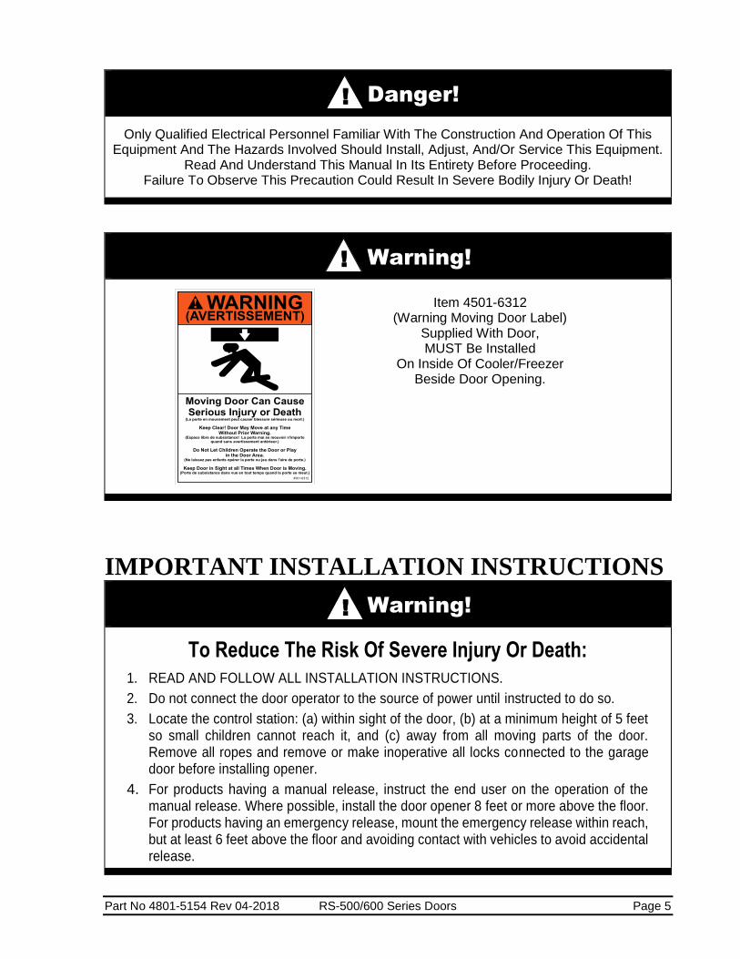
Part No 4801-5154 Rev 04-2018 RS-500/600 Series Doors Page 5
Danger!
Only Qualified Electrical Personnel Familiar With The Construction And Operation Of This Equipment And The Hazards Involved Should Install, Adjust, And/Or Service This Equipment.
Read And Understand This Manual In Its Entirety Before Proceeding. Failure To Observe This Precaution Could Result In Severe Bodily Injury Or Death!
Warning!
IMPORTANT INSTALLATION INSTRUCTIONS
Warning!
To Reduce The Risk Of Severe Injury Or Death:
1. READ AND FOLLOW ALL INSTALLATION INSTRUCTIONS.
2. Do not connect the door operator to the source of power until instructed to do so.
3. Locate the control station: (a) within sight of the door, (b) at a minimum height of 5 feet so small children cannot reach it, and (c) away from all moving parts of the door. Remove all ropes and remove or make inoperative all locks connected to the garage door before installing opener.
4. For products having a manual release, instruct the end user on the operation of the manual release. Where possible, install the door opener 8 feet or more above the floor. For products having an emergency release, mount the emergency release within reach, but at least 6 feet above the floor and avoiding contact with vehicles to avoid accidental release.
!
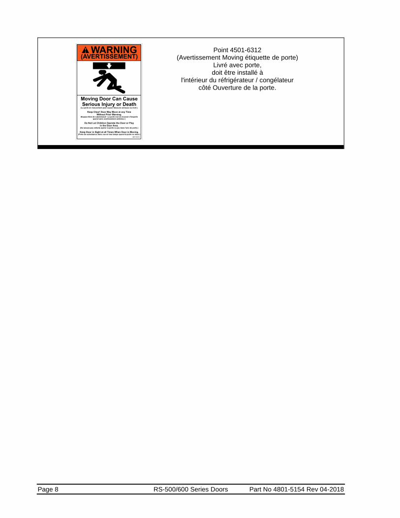
Item 4501-6312 (Warning Moving Door Label)
Supplied With Door, MUST Be Installed
On Inside Of Cooler/Freezer Beside Door Opening.
!
!
!
Page 6 RS-500/600 Series Doors Part No 4801-5154 Rev 04-2018
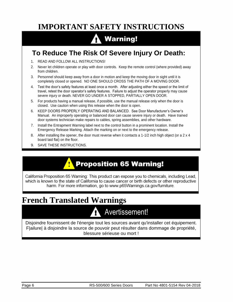
IMPORTANT SAFETY INSTRUCTIONS
Warning!
To Reduce The Risk Of Severe Injury Or Death: 1. READ AND FOLLOW ALL INSTRUCTIONS!
2. Never let children operate or play with door controls. Keep the remote control (where provided) away from children.
3. Personnel should keep away from a door in motion and keep the moving door in sight until it is completely closed or opened. NO ONE SHOULD CROSS THE PATH OF A MOVING DOOR.
4. Test the door’s safety features at least once a month. After adjusting either the speed or the limit of travel, retest the door operator’s safety features. Failure to adjust the operator properly may cause severe injury or death. NEVER GO UNDER A STOPPED, PARTIALLY OPEN DOOR.
5. For products having a manual release, if possible, use the manual release only when the door is closed. Use caution when using this release when the door is open.
6. KEEP DOORS PROPERLY OPERATING AND BALANCED. See Door Manufacturer’s Owner’s Manual. An improperly operating or balanced door can cause severe injury or death. Have trained door systems technician make repairs to cables, spring assemblies, and other hardware.
7. Install the Entrapment Warning label next to the control button in a prominent location. Install the Emergency Release Marking. Attach the marking on or next to the emergency release.
8. After installing the opener, the door must reverse when it contacts a 1-1/2 inch high object (or a 2 x 4 board laid flat) on the floor.
9. SAVE THESE INSTRUCTIONS.
French Translated Warnings
Avertissement!
Disjoindre fournissent de l'énergie tout les sources avant qu'installer cet équipement. F|ailure| à disjoindre la source de pouvoir peut résulter dans dommage de propriété,
blessure sérieuse ou mort !
!
! !

Part No 4801-5154 Rev 04-2018 RS-500/600 Series Doors Page 7
Avertissement !
Tout montage sur fil de fer doit être selon codes électriques nationaux ou autres indicatifs régionaux.
Avertissement !
L'Installer est responsable pour conformer avec tout règlement pertinent, telles que règlement et règlement de prévention d'accident de montage sur fil de fer nationaux. Pl'attention articulaire doit être donnée pour les aires sectionnelles transversales de conducteurs, le choix d'elles fusées ou autre protection, et terre / prises de terre protecteur !
Avertissement !
Les tensions dans le pouvoir câblent et certains parties de la promenade en voiture peuvent résulter dans la mort. Wle |henever| la promenade en voiture a été utilisé il doit être isolé et détaché pendant 5 procès avant que tout travail commence.
Danger !
Seulement familier électrique de personnel qualifié avec la construction et opération de cet équipement et les hasards ont enveloppé devoir installer, arranger, et/ou - la révision cet équipement. R|ead| et comprendre ce manuel en entier avant que procéder. F|ailure| à observer cette précaution peut résulter dans dommage corporel sévère ou mort !
Avertissement !
Avertissement !
Mécanisme tournant dangereux ! Garder les mains, vêtissant, etcC|lear| quand fonctionner !
Ne fonctionnez pas sans toutes gardes et couvertures dans lieu !
!
!
!
!
!
!
!
!
Page 8 RS-500/600 Series Doors Part No 4801-5154 Rev 04-2018
Point 4501-6312 (Avertissement Moving étiquette de porte)
Livré avec porte, doit être installé à
l'intérieur du réfrigérateur / congélateur côté Ouverture de la porte.

Part No 4801-5154 Rev 04-2018 RS-500/600 Series Doors Page 9
LES INSTRUCTIONS D'INSTALLATION
IMPORTANTES
AVERTISSEMENT!
À réduire le risque de blessure sévère ou mort:
1. LU ET SUIVENT TOUTES INSTRUCTIONS D'INSTALLATION.
2. Ne liez pas l'opérateur de porte per la source de pouvoir jusqu'à instruit faire ainsi.
3. Localisez la station de commande: (a) en vue de la porte, (b) à un minimum la hauteur de 5 pieds ainsi petit enfants ne peuvent pas l'atteindre, et (c) loin de tous parties en mouvement de la porte.
4. Pour produits ayant un délivrance manuelle, instruire l'utilisateur final sur l'opération de la délivrance manuelle.
RÈGLEMENTS DE SÉCURITÉ IMPORTANTS
AVERTISSEMENT!
À réduire le risque de blessure sévère ou mort: 1. LU ET SUIVENT TOUTES INSTRUCTIONS!
2. Jamais laisser fonctionner enfants ou mouvoir vivement avec les autorités de porte. Gardez la télécommande (où a fourni) loin des enfants.
3. Le personnel devrait garder loin une porte dans mouvement et subsistance la porte en mouvement dans vue jusqu'à est complètement fermé ou avoir ouvert. CES AUCUNS DOIVENT CROISER LE CHEMIN D'UNE PORTE EN MOUVEMENT.
4. Éprouvez les traits de sécurité de la porte au moins une fois par mois. Après qu'arrangeant la vitesse ou la fin de course, retest les traits de sécurité de l'opérateur de porte. Manque à arranger l'opérateur correctement peut causer blessure sévère ou mort.
5. Pour produits ai manuel la délivrance, si possible, utiliser la délivrance manuelle seulement quand la porte est fermée. Précaution d'utilisation à utiliser cette délivrance quand la porte est ouverte.
6. GARDER LES PORTES CORRECTEMENT QUI OPÈRE ET ÉQUILIBRÉ. Voir la porte fabricant propriétaire manuel. Un improprement qui opère ou balancé porte peut causer blessure sévère ou mort. Formez les technicien de systèmes de porte faitez les réparations per les câbles, réunions de source, et autre quincaillerie.
7. SAUVEZ CES INSTRUCTIONS.
!
!

Page 10 RS-500/600 Series Doors Part No 4801-5154 Rev 04-2018
2 Limited Warranty
All products are warranted to be free from defects in material and workmanship for a period of one
(1) year or 100,000 cycles, whichever occurs first, from the date of purchase if installed and used
in strict accordance with the installation instructions. Liability is limited to the sale price of any
products proved to be defective or, at manufacturers’ option, to the replacement of such products
upon their return. No products are to be returned to the manufacturer, until there is an inspection
and/or a return-goods authorization (RGA) number is issued.
All complaints should be directed first to the authorized distributor who sold the product. If
satisfaction is not obtained or the name of the distributor is not known, write the manufacturer that
appears below, directed to the attention of Customer Service Manager.
This limited warranty is expressly in lieu of any and all representations and warranties expressed
or implied, including any implied warranty of merchantability or fitness for a particular purpose.
The remedy set forth in this limited warranty shall be the exclusive remedy available to any person.
No person has authority to bind the manufacturer to any representation or warranty other than this
limited warranty. The manufacturer shall not be liable for any consequential damages resulting
from the use of our products or caused by any defect, failure or malfunction of our products. (Some
areas do not allow the exclusion or limitation of incidental or consequential damages, so the above
limitation or exclusion may not apply to you.)
This warranty gives you specific legal rights and you may also have other rights that vary from area
to area.
Warrantor:
RollSeal
1733 County Road 68
Bremen, Al 35055
256-287-7000

Part No 4801-5154 Rev 04-2018 RS-500/600 Series Doors Page 11
*NOTE: When Brother Motor Option is used you can request that a RS-500
Door be wired for 115VAC or 230VAC. The RS-600 is wired for 230
VAC only. This must be done prior to purchase to ensure the door
has the correct brake rectifier installed.
3 Use of Equipment The RS-500/600 Series Doors are motorized curtain enclosures for environmental control, ripening rooms,
docks/warehouses, car and truck washes, agricultural/horticultural, and coolers/freezers.
4 Physical Description The RS-500/600 Series Doors are available with multiple features and options such as:
Standard Door Sizes: Refer to Tables 1-4, RS-500/600 Series Standard Dimensions, Sections 0, 9, 10,
and 11.
Operators: Manual Chain Hoist, Brother or Manaras Operator.
Left/Right/Front Mounting: The Manaras Operators can be mounted on the left, right, or front. The
manual chain hoist can be mounted on the left or right side. The Operator Mounting Side must be selected
at the time of order.
Left Mounting Only: The Brother motor can only be mounted on the left side, the associated controller, on
the right side.
Manaras Operator Voltage Selection: 1/2 HP, Single Phase: 115V @ 8.6 amp, 230V @ 4.1 amp. 1/2 HP,
3 Phase: 208V @ 2.2 amp, 460V @ 1.1 amp. 1 HP, Single Phase: 115V @ 13.4 amp, 230V @ 6.7 amp. 1
HP, 3 Phase: 208V @ 3.4 amp, 460V @ 1.7 amp.
RS-500 with Brother Motor - Controller Standard Input Voltage 115VAC (Must request 230VAC).
RS-600 with Brother Motor - Controller Standard Input Voltage 230VAC.
Operator Options: Remote receiver and transmitters, photo safety beams, leading edge switch.
Accessories: Industry standard accessories can be added such as motion sensors, loop detectors, ceiling
pull switches, lock-out switches, other various types of switches, and door status / movement indicators
such as lights and buzzers.
Windows: 32" high with width varying by width of door panel.
Fabric & Fabric Colors: Frost, white, black, blue, red yellow, silver, tan, green, anti-static, and insect
screen.
NOTE: Certain options may only be available with specific operators. Refer to Section 39.5,
RS-500/600 Door Options and Accessories.
5 Differences between a RS-500 and RS-600 Series Door
RS-500 Series RS-600 Series Speed (Brother Motor Option) Up to 18” Per Sec Up to 48” Per Sec
Speed (Manaras Motor) @8-11” Per Sec @16-22” Per Sec
Motor (Brother) 1/4hp 1/2hp
Motor (Manaras) 1/2hp GH 1hp GH
Drive Pipe 2 ½ inches 6 inches
Head Unit Small Large
*Standard Controller Input Voltage 115VAC 230VAC
(Brother Motor Option)

Page 12 RS-500/600 Series Doors Part No 4801-5154 Rev 04-2018
6 Operator Options
NSF Certified Doors are equipped with
Left mount Brother operators, Smart Controller,
and Magnetic Track Sealing System

Part No 4801-5154 Rev 04-2018 RS-500/600 Series Doors Page 13
7 Ratings and Specifications
RS-500/600 Series (Brother Motor)
RS-500 Doors
Part Number 6607-8057 6607-8056 6607-8058 6607-8060 6607-8061
Model Number SC-325-V01-115 SC-325-V02-0 SC-325-V01-115-W01 SC-325-V01-115-
PLUS SC-325-V01-230-
PLUS
Power Supply
115 VAC 50/60 Hz Single Phase is Factory Pre-Set
230 VAC 50/60 Hz Single Phase see.
RollSeal SC-325 & SC-650 Controllers Owner’s Manual
Section 12-12.1 Diagram 12A
115 VAC or 230 VAC 50/60 Hz
Single Phase
230 VAC 50/60 Hz
Single Phase
Temperature Range
32°F - 115°F (0°C – 46°C)
Inputs 10 Amps @ 115 VAC Single Phase or
6 Amps @ 230 VAC Single Phase
10 Amps @ 115 VAC
Single Phase
6 Amps @ 230 VAC
Single Phase
Outputs 230 VAC Three Phase 1/4 H.P.
Drive Setting Version 01 Version 02 Version 01 Version 01 Version 01
Factory Preset Voltage Switch
& Jumper 115 VAC 230 VAC
Switch & Warning Wires with Conduit
N/A Switch Wiring Option
Optional Condensation Management System DOOR MOTOR: 230 VAC Three Phase, ¼ hp CONDENSATION MANAGEMENT SYSTEM (CMS): Voltage Rating 230 VAC ± 10% 50/60 Hz
Blower 135 Watt
Heater 1200 Watt
Total Current: 6.0 A @ 230 VAC (Typical)
9.0 A @ 230 VAC (Max.)
RS-600 Doors
Part Number 6607-8100 6607-8101 6607-8102 6607-8103
Model Number SC-650-V01-0 SC-650-V02-0 SC-650-V01-W01-PLUS SC-650-V02-W01-PLUS
Power Supply 230 VAC 50/60 Hz Single Phase
Temperature Range 32°F - 115°F (0°C – 46°C)
Inputs 8 Amps @ 230 VAC Single Phase
Outputs 230 VAC Three Phase 1/2 H.P.
Drive Setting Version 01 Version 02 Version 01 Version 02
Factory Preset Voltage Switch & Jumper
230 VAC
Switch & Warning Wires with Conduit
N/A Switch Wiring Option
NSF Certified Doors are equipped
with Left mount Brother operators,
Smart Controller, and Magnetic Track Sealing System

Page 14 RS-500/600 Series Doors Part No 4801-5154 Rev 04-2018
RS-500
Door
Height
B C
In. cm In. cm
7' (H) 84 213 104 11/16 266
7' 6" (H) 90 229 110 11/16 281
8' (H) 96 244 116 11/16 296
9' (H) 108 274 128 11/16 327
10' (H) 120 305 140 11/16 357
11' (H) 132 335 152 11/16 388
12' (H) 144 366 164 11/16 418
8 RS-500 Series Door (Brother Motor) See Section 7 for Ratings and Specifications.
Motor must be connected through Controller.
TABLE 1 RS-500 Door Standard Dimensions:
WIDTH Related Dimensions HEIGHT Related Dimensions
RS-500
Door
Width
A D E
In. cm In. cm In. cm
4' (W) 48 122 64 3/8 164 82 5/16 209
5' (W) 60 152 76 3/8 194 94 5/16 240
6' (W) 72 183 88 3/8 225 106 5/16 270
6' 6" (W) 78 198 94 3/8 240 112 5/16 286
7' (W) 84 213 100 3/8 255 118 5/16 301
8' (W) 96 244 112 3/8 285 130 5/16 331
9' (W) 108 274 124 3/8 316 142 5/16 362
10' (W) 120 305 136 3/8 346 154 5/16 392
11' (W) 132 335 148 3/8 377 166 5/16 423
12' (W) 144 366 160 3/8 407 178 5/16 453
NSF Certified Doors are equipped with Left mount Brother operators,
Smart Controller, and Magnetic
Track Sealing System

Part No 4801-5154 Rev 04-2018 RS-500/600 Series Doors Page 15
RS-600
Door
Height
B C
In. cm In. cm
7' (H) 84 213 108 274
7’ 6” (H) 90 229 114 290
8' (H) 96 244 120 305
9' (H) 108 274 132 335
10' (H) 120 305 144 366
11' (H) 132 335 156 396
12' (H) 144 366 168 427
9 RS-600 Series Door (Brother Motor) See Section 7 for Ratings and Specifications.
Motor must be connected through Controller.
TABLE 2 RS-600 Door Standard Dimensions:
WIDTH Related Dimensions HEIGHT Related Dimensions
RS-600
Door
Width
A D E
In. cm In. cm In. cm
4' (W) 48 122 64 3/8 164 82 5/16 209
5' (W) 60 152 76 3/8 194 94 5/16 240
6' (W) 72 183 88 3/8 225 106 5/16 270
6’ 6” (W) 78 198 94 3/8 240 112 5/16 286
7' (W) 84 213 100 3/8 255 118 5/16 301
8' (W) 96 244 112 3/8 285 130 5/16 331
9' (W) 108 274 124 3/8 316 142 5/16 362
10' (W) 120 305 136 3/8 346 154 5/16 392
11' (W) 132 335 148 3/8 377 166 5/16 423
12' (W) 144 366 160 3/8 407 178 5/16 453
NSF Certified Doors are equipped
with Left mount Brother operators,
Smart Controller, and Magnetic Track Sealing System

Page 16 RS-500/600 Series Doors Part No 4801-5154 Rev 04-2018
RS-600
Door
Height
B C
In. cm In. cm
7' (H) 84 213 104 11/16 266
7’ 6” (H) 90 229 110 11/16 281
8' (H) 96 244 116 11/16 296
9' (H) 108 274 128 11/16 327
10' (H) 120 305 140 11/16 357
11’ (H) 132 335 152 11/16 388
12’ (H) 144 366 164 11/16 418
10 RS-500 Series Door with Optional
Condensation Management System See Section 7 for Ratings and Specifications.
Motor must be connected through Controller.
WIDTH Related Dimensions HEIGHT Related Dimensions
RS-600
Door
Width
A D E
In. cm In. Cm In. cm
4' (W) 48 122 77 1/2 197 82 7/16 209
5' (W) 60 152 89 1/2 227 94 7/16 240
6' (W) 72 183 101 1/2 258 106 7/16 270
6’ 6” (W) 78 198 107 1/2 273 112 7/16 286
7' (W) 84 213 113 1/2 288 118 7/16 301
8' (W) 96 244 125 1/2 319 130 7/16 331
9' (W) 108 274 137 1/2 349 142 7/16 362
10' (W) 120 305 149 1/2 380 154 7/16 392
11' (W) 132 335 161 1/2 410 166 7/16 423
12' (W) 144 366 173 1/2 441 178 7/16 453
TABLE 3 RS-500 Door with Freezer Kit
Dimensions:
NSF Certified Doors are equipped
with Left mount Brother operators,
Smart Controller, and Magnetic Track Sealing System

Part No 4801-5154 Rev 04-2018 RS-500/600 Series Doors Page 17
RS-600
Door
Height
B C
In. cm In. cm
7' (H) 84 213 108 274
7’ 6” (H) 90 229 114 290
8' (H) 96 244 120 305
9' (H) 108 274 132 335
10' (H) 120 305 144 366
11’ (H) 132 335 156 396
12’ (H) 144 366 168 427
11 RS-600 Series Door with Optional
Condensation Management System
See Section 7 for Ratings and Specifications.
Motor must be connected through Controller.
TABLE 4 RS-600 Door with Freezer Kit Dimensions:
WIDTH Related Dimensions HEIGHT Related Dimensions
RS-600
Door
Width
A D E
In. cm In. Cm In. cm
4' (W) 48 122 77 1/2 197 82 7/16 209
5' (W) 60 152 89 1/2 227 94 7/16 240
6' (W) 72 183 101 1/2 258 106 7/16 270
6’ 6” (W) 78 198 107 1/2 273 112 7/16 286
7' (W) 84 213 113 1/2 288 118 7/16 301
8' (W) 96 244 125 1/2 319 130 7/16 331
9' (W) 108 274 137 1/2 349 142 7/16 362
10' (W) 120 305 149 1/2 380 154 7/16 392
11' (W) 132 335 161 1/2 410 166 7/16 423
12' (W) 144 366 173 1/2 441 178 7/16 453
NSF Certified Doors are equipped
with Left mount Brother operators,
Smart Controller, and Magnetic Track Sealing System
Page 18 RS-500/600 Series Doors Part No 4801-5154 Rev 04-2018
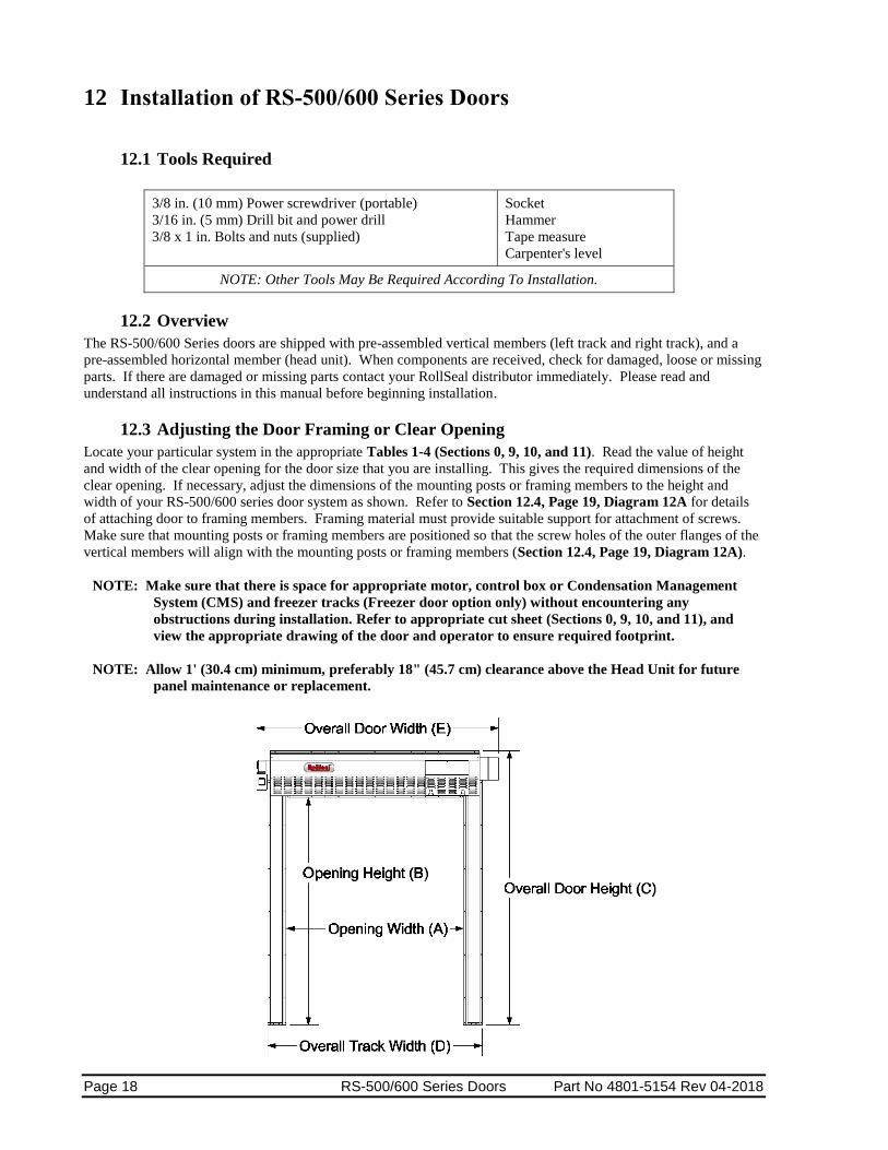
12 Installation of RS-500/600 Series Doors
12.1 Tools Required
3/8 in. (10 mm) Power screwdriver (portable)
3/16 in. (5 mm) Drill bit and power drill
3/8 x 1 in. Bolts and nuts (supplied)
Socket
Hammer
Tape measure
Carpenter's level
NOTE: Other Tools May Be Required According To Installation.
12.2 Overview
The RS-500/600 Series doors are shipped with pre-assembled vertical members (left track and right track), and a
pre-assembled horizontal member (head unit). When components are received, check for damaged, loose or missing
parts. If there are damaged or missing parts contact your RollSeal distributor immediately. Please read and
understand all instructions in this manual before beginning installation.
12.3 Adjusting the Door Framing or Clear Opening
Locate your particular system in the appropriate Tables 1-4 (Sections 0, 9, 10, and 11). Read the value of height
and width of the clear opening for the door size that you are installing. This gives the required dimensions of the
clear opening. If necessary, adjust the dimensions of the mounting posts or framing members to the height and
width of your RS-500/600 series door system as shown. Refer to Section 12.4, Page 19, Diagram 12A for details
of attaching door to framing members. Framing material must provide suitable support for attachment of screws.
Make sure that mounting posts or framing members are positioned so that the screw holes of the outer flanges of the
vertical members will align with the mounting posts or framing members (Section 12.4, Page 19, Diagram 12A).
NOTE: Make sure that there is space for appropriate motor, control box or Condensation Management
System (CMS) and freezer tracks (Freezer door option only) without encountering any
obstructions during installation. Refer to appropriate cut sheet (Sections 0, 9, 10, and 11), and
view the appropriate drawing of the door and operator to ensure required footprint.
NOTE: Allow 1' (30.4 cm) minimum, preferably 18" (45.7 cm) clearance above the Head Unit for future
panel maintenance or replacement.

Part No 4801-5154 Rev 04-2018 RS-500/600 Series Doors Page 19
12.4 Attachment Points of Door
When sizing the clear opening for attachment of the door, pay close attention to the following guidelines. Door
flanges have pre-drilled holes that serve as mounting points of door.
Flange widths are shown in Diagram 12A.
1. Make sure that door assembly is plumb & square.
2. The top unit has a top flange and a bottom flange. Make sure these flanges overlap framing.
3. The vertical members have inner flanges and outer flanges. The inner and outer flanges have pre-drilled
holes that serve as attachment points. Make sure the outer flanges overlap framing.
4. When door is raised in front of clear opening (Section 12.8, Page 22), Diagram flanges must be flush
against framing for attachment of screws.
Diagram 12A
Bottom View
Framing Members

Page 20 RS-500/600 Series Doors Part No 4801-5154 Rev 04-2018
12.5 Assembly of Tracks
Taller doors that require a total track length over 13’ have spliced tracks. If track sections need to be
assembled, follow the instructions shown below.
1. Arrange the Top and Bottom Tracks so that they can be assembled. See Diagram 12B.
2. Slide the Bottom Track into the Top Track so that the Tracks butt together on the Splice Bracket and
Splice Plate. See Diagram 12C.
3. Note that the Tracks butt together inside the Track Bracket and butt together on top of the Track
Plate.
4. Bolt the Tracks together. Check that ALL bolts in the Splice Bracket and Splice Plate are properly
tightened.

Part No 4801-5154 Rev 04-2018 RS-500/600 Series Doors Page 21
12.6 Assembly of Tracks to the Head Unit
Arrange the horizontal member, left vertical member (left track), and right vertical member (right track) on
the floor in front of the clear opening as shown in Diagram 12D. The curtain side of the horizontal member
and each vertical member faces down.
Diagram 12D
A B
Placement of Parts for Assembly
Lay left track, right track, and horizontal member
face down in front of the clear opening as shown.
End of horizontal
Member
U-shaped
plate
Plate fits inside vertical member
Slide vertical member over U-shaped plate.
Vertical Member
Clear Opening At this end of members
3/8" x 1"
Bolts & nuts
On each end of the horizontal member is a
U-shaped plate that fits inside each
vertical member. The U-shaped plate has
four bolt holes, two on the inside and two
on the outside flanges that match bolt
holes in the vertical member. See diagram
at left.
1. Align the vertical member with the
U-shaped metal plate at end of
horizontal member.
2. Slide the vertical member onto the
outside of the U-shaped metal plate of
the horizontal member as shown in A.
3. Insert bolts through bolt holes as shown
in B. Install nuts. Tighten bolts & nuts
securely.

Page 22 RS-500/600 Series Doors Part No 4801-5154 Rev 04-2018
12.7 Infrared Sensor Connectors (Brother Motor Option Only)
Located at the bottom of each vertical member is an infrared detector. The detector on each vertical member
operates as a safety device if the infrared beam is interrupted. Door can be set to stop if beams are broken
while closing or to stop and reverse to the full open position. Refer to the RollSeal SC-325 and SC-650
Controller Manual for more information.
1. Locate female connector on vertical member. This connector is attached to the infrared detector.
2. Locate male connector on horizontal member. Unroll cable until connectors meet. Pull enough slack to
create a service loop, such that connectors can be pulled out of tracks for photo eye replacement and
troubleshooting purposes.
3. Plug connectors together. Make sure connectors interlock.
4. Repeat for both infrared detectors.
5. Cable ties and adhesive mounts are supplied to secure wire to the inside of tracks.
Diagram 12E
12.8 Fastening Door Assembly to Clear Opening
Diagram 12F
1. Use a tape measure and make sure that the overall
height and overall width of the clear opening meet
the door requirements.
Reference appropriate Table 1-4, Sections 0, 9, 10,
and 11.
2. Make sure that door assembly is plumb & square.
See Diagram 12F.
3. Center door assembly on clear opening. Align the
bottom of each vertical member with the respective
framing board or posts of the clear opening.
NOTE: For each vertical member, unroll respective sensor
cable attached to horizontal member until cable
reaches the sensor connector attached to the
vertical member.
NOTE: Pull Enough Slack To Leave A Service Loop
For Photo Eye Replacement And
Troubleshooting Purposes
Part No 4801-5154 Rev 04-2018 RS-500/600 Series Doors Page 23
NOTE: The vertical members should
be aligned so that their outer
flanges will exactly overlap
with the framing boards or
posts when the door
assembly is raised into
position.
4. Assemble workers and
equipment into position on
each side of the door assembly.
IMPORTANT: SLOWLY LIFT TOP
OF DOOR ASSEMBLY TO
RAISE THE DOOR. See
Diagram 12G.
Diagram 12H
5. Lean door assembly upright against clear opening.
6. Carefully press flanges of the door assembly flush against faces of framing boards or posts.
7. Fasten Tek screws (in steel) or lag screws (in wood) through the flanges on sides of door assembly.
Securely tighten all screws.
8. On the lower and upper flanges of the horizontal member there are attachment points for fastening
screws. Fasten Tek screws (in steel) or lag screws (in wood) through the holes. This secures the top of
the door to the clear opening.
9. Locate the two floor mounting holes at the bottom of the left and right tracks. See Diagram 12H.
10. Drill a 1/4" hole and install Hammer Set Anchors (1002-6030) in both right and left tracks. See
Diagram 12H.
11. This completes fastening of the door assembly to the clear opening.

Page 24 RS-500/600 Series Doors Part No 4801-5154 Rev 04-2018
13 Manaras Motor Mounting to RS-500/600 Series Doors
Warning!
Prior to mounting the Manaras it is important that you read all the information contained within this document and the Manaras Installation and Instruction Manual provided with the
door. Failure to do so could result in severe personnel injury or damage to equipment!
For more detailed information on mounting, wiring and operating the Manaras, refer to the Manaras Installation and
Instruction Manual provided with the door.
Sprockets are mounted as follows on RS-500/600 Series Doors:
RS500: 50-23 (motor) & 50-12 (door)
RS600: 50-12 (motor) & 50-23 (door)
Optional: 50-12 (motor & door) [Special Order]
! !
RS-600 Series Motor Rating 1 HP (if
the door is more than 13 feet wide)
115V Single Phase 13.4 amp
230V Single Phase 6.7 amp
208V 3 Phase 3.4 amp
460V 3 Phase 1.7 amp
RS-500 Series Motor Rating 1/2 HP
115V Single Phase 8.6 amp
230V Single Phase 4.1 amp
208V 3 Phase 3.4 amp
460V 3 Phase 1.7 amp
Part No 4801-5154 Rev 04-2018 RS-500/600 Series Doors Page 25
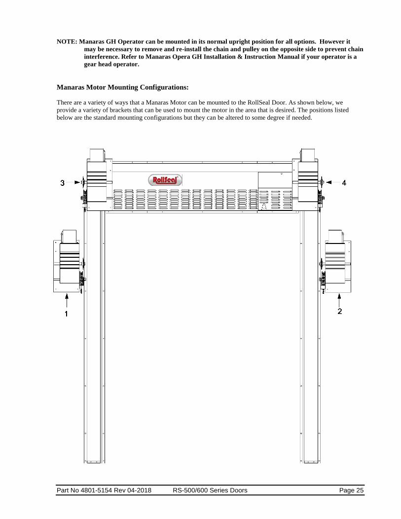
NOTE: Manaras GH Operator can be mounted in its normal upright position for all options. However it
may be necessary to remove and re-install the chain and pulley on the opposite side to prevent chain
interference. Refer to Manaras Opera GH Installation & Instruction Manual if your operator is a
gear head operator.
Manaras Motor Mounting Configurations:
There are a variety of ways that a Manaras Motor can be mounted to the RollSeal Door. As shown below, we
provide a variety of brackets that can be used to mount the motor in the area that is desired. The positions listed
below are the standard mounting configurations but they can be altered to some degree if needed.

Page 26 RS-500/600 Series Doors Part No 4801-5154 Rev 04-2018
POSITION 1 – GH motor mounted on the left side.
Parts Required – Wall Mount Bracket (6450-0907), normal size spreader bar, normal size chain, 2 collars and 2
sprockets. (1 size 50-12 and 1 50-23)
5 6
Part No 4801-5154 Rev 04-2018 RS-500/600 Series Doors Page 27
POSITION 2 – GH motor mounted on the right side.
Parts Required – Wall Mount Bracket (6450-0907), normal size spreader bar, normal size chain, 2 collars and 2
sprockets. (1 size 50-12 and 1 50-23)
POSITION 3 – GH motor mounted on the left side.
Parts Required – Front Mount Bracket (6421-6543 {D5} or 6421-6542 {D6}), normal size spreader bar, normal
size chain, 2 collars and 2 sprockets. (1 size 50-12 and 1 50-23)
POSITION 4 – GH motor mounted on the right side.
Parts Required – Front Mount Bracket (6421-6543 {D5} or 6421-6542 {D6}), normal size spreader bar, normal
size chain, 2 collars and 2 sprockets. (1 size 50-12 and 1 50-23)
POSITION 5 – GH motor mounted on the left side.
Parts Required – Overhead Booth Mount Bracket (6450-0906), normal size spreader bar, normal size chain, 2
collars and 2 sprockets. (1 size 50-12 and 1 50-23)
POSITION 6 – GH motor mounted on the right side.
Parts Required – Overhead Booth Mount Bracket (6450-0906), normal size spreader bar, normal size chain, 2
collars and 2 sprockets. (1 size 50-12 and 1 50-23)
As shown above, there are six standard mounting positions for the Manaras Motor. These six mounting positions
require the use of one of the three mounting brackets which can be used on the left or right hand side of the door. In
order to better understand the three Manaras Mounting Brackets, they are detailed below to include installation
instructions.
WARNING: Due to the uncertainty of the mounting surface and booth construction, the
installation technician is responsible to ensure that the bracket is secured in a safe manner. There
may be a scenario where bracing has to be added to stiffen the booth in the mounting location.
Wall Mount Bracket: (Position 1 & 2)
1. Position the Manaras Wall Mount Bracket (0404-14293), to the wall of the booth in the required location.
The installation technicians are responsible for providing the correct mounting hardware from the below
information to ensure a secure constraint.
a. Before mounting the bracket, ensure that the Manaras Motor Output Shaft and the Door Shaft are
in the correct position in respect to each other.
b. Due to the nature of the loading configuration, there is a substantial tensile and shear load on the
fasteners that connect the mounting bracket to the wall.
c. Due to the magnitude of the load and the uncertainty in the vibratory load, HHT does not provide
a definite mounting solution that will work with all booths. Below are three mounting
configurations that have been used in the past that have worked depending on the structure of the
booth.
1). Ideally HHT recommends mounting to structural support bracing if present with 3/8” hex head
bolts (not provided).
2). If no support bracing is present in the top of the booth, HHT recommends through bolting the
bracket with 3/8” thru-bolts (not provided).
3). In the case that neither of the previously mentioned mounting scenarios are possible, assuming
that the wall material is 18 gauge or greater, HHT recommends using the six (6) provided Fab-
Loks to secure the bracket to the wall of the booth.
d. Configuration 1 and 2 are optimal due to the uncertainty in the vibratory load. Configuration 3
may allow vibration during operation. The installation technician is responsible to ensure that
there is not excess vibration during operation.
2. Once the Motor Mount Bracket is mounted and secured as described, mount the motor to the bracket with
the provided 3/8” bolts (4). Place a washer between the nut and the inside of the bracket slot and hand
tighten the motor mount hardware in the slotted holes.
3. The motor will have to be adjusted depending on the mounting position as described in MANARAS
Installation and Instruction Manual.
4. Once the motor is in the correct mounting position, tighten the hardware with the required 9/16” wrenches.

Page 28 RS-500/600 Series Doors Part No 4801-5154 Rev 04-2018
Front Mount Bracket: (Position 3 & 4)
1. The Manaras Front Mount Bracket is preinstalled prior to shipment. HHT recommends that all the bracket
assembly fasteners be checked to ensure nothing has vibrated loose during transport.
2. Once the Door is installed and all the fasteners have been secured, the motor can be mounted to the front
mount bracket.
3. There will be four (4) 3/8” hex head bolts provided with the front mount bracket and will be hand tightened
in the motor mounting slots shown in Figure 1 on the front of the bracket for shipping purposes.
4. Remove these four (4) bolts and lift the motor into place. Once the motor is aligned, insert the 3/8” bolts
through the motor mount base and into the slots on the front of the bracket. Place the provided washers and
lock nuts on the inside of the bracket and tighten until the nuts are snug with the required 9/16” wrench.
5. The motor will have to be adjusted depending on the mounting position as described in MANARAS
Installation and Instruction Manual.
6. Once the motor is in the correct mounting position, and the chain and spreader bar are set correctly, tighten
the motor mount hardware.
7. The figure below shows how the Manaras Motor should look once it is fully installed.

Part No 4801-5154 Rev 04-2018 RS-500/600 Series Doors Page 29
Overhead Booth Mount Bracket: (Position 5 & 6)
1. Position the Manaras Motor Mount Bottom Bracket (0404-14299) to the top of the booth in the required
location. The installation technicians are responsible for providing the correct mounting hardware from the
below information to ensure a secure constraint.
a. In order to keep the Manaras Motor Output Shaft and the Door Shaft in the correct position in
respect to each other, the mounting bracket may need to be slid over the edge of the booth as
shown in the below figures.
b. Due to the nature of the loading configuration, HHT does not recommend sliding the bracket over
the edge of the booth more than eight (8) inches. This is due to the uncertainty of the mounting
surface.
c. With the previously described mounting position, there is a substantial tensile load placed on the
mounting fasteners. Due to the magnitude of the load and the uncertainty in the vibratory load,
HHT does not provide a definite mounting solution that will work with all booths. Below are three
mounting configurations that have been used in the past that have worked depending on the
structure on the booth.
1). Ideally HHT recommends mounting to structural support bracing if present with 3/8” hex head
bolts (not provided).
2). If no support bracing is present in the top of the booth, HHT recommends through bolting the
bracket with 3/8” thru-bolts (not provided).
3). In the case that neither of the previously mentioned mounting scenarios are possible, assuming
that the roof material is 18 gauge or greater, HHT recommends using the six (6) provided Fab-
Loks to secure the bracket to the top of the booth.
d. Configuration 1 and 2 are optimal due to the uncertainty in the vibratory load. Configuration 3
may allow vibration during operation. The installation technician is responsible to ensure that
there is not excess vibration during operation.
Page 30 RS-500/600 Series Doors Part No 4801-5154 Rev 04-2018
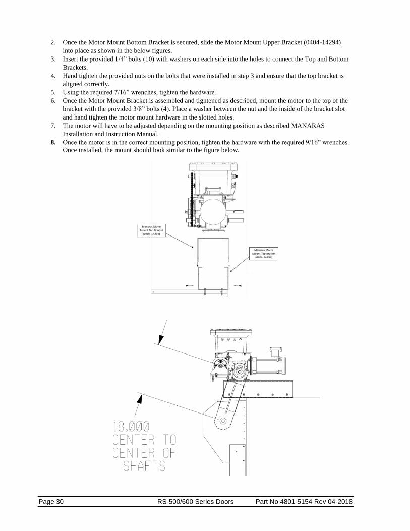
2. Once the Motor Mount Bottom Bracket is secured, slide the Motor Mount Upper Bracket (0404-14294)
into place as shown in the below figures.
3. Insert the provided 1/4” bolts (10) with washers on each side into the holes to connect the Top and Bottom
Brackets.
4. Hand tighten the provided nuts on the bolts that were installed in step 3 and ensure that the top bracket is
aligned correctly.
5. Using the required 7/16” wrenches, tighten the hardware.
6. Once the Motor Mount Bracket is assembled and tightened as described, mount the motor to the top of the
bracket with the provided 3/8” bolts (4). Place a washer between the nut and the inside of the bracket slot
and hand tighten the motor mount hardware in the slotted holes.
7. The motor will have to be adjusted depending on the mounting position as described MANARAS
Installation and Instruction Manual.
8. Once the motor is in the correct mounting position, tighten the hardware with the required 9/16” wrenches.
Once installed, the mount should look similar to the figure below.
Part No 4801-5154 Rev 04-2018 RS-500/600 Series Doors Page 31
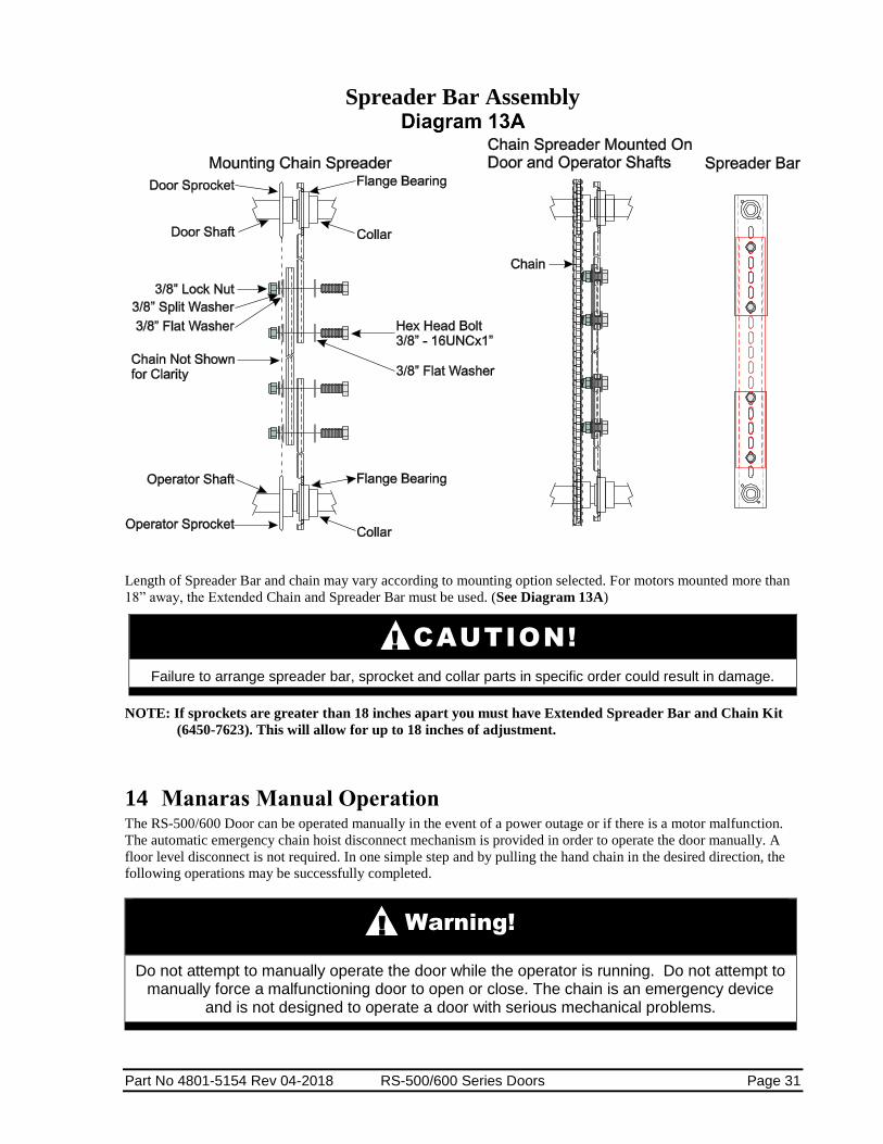
Spreader Bar Assembly
Length of Spreader Bar and chain may vary according to mounting option selected. For motors mounted more than
18” away, the Extended Chain and Spreader Bar must be used. (See Diagram 13A)
CAUTION!
Failure to arrange spreader bar, sprocket and collar parts in specific order could result in damage.
NOTE: If sprockets are greater than 18 inches apart you must have Extended Spreader Bar and Chain Kit
(6450-7623). This will allow for up to 18 inches of adjustment.
14 Manaras Manual Operation The RS-500/600 Door can be operated manually in the event of a power outage or if there is a motor malfunction.
The automatic emergency chain hoist disconnect mechanism is provided in order to operate the door manually. A
floor level disconnect is not required. In one simple step and by pulling the hand chain in the desired direction, the
following operations may be successfully completed.
Warning!
Do not attempt to manually operate the door while the operator is running. Do not attempt to manually force a malfunctioning door to open or close. The chain is an emergency device
and is not designed to operate a door with serious mechanical problems.
!
!

Page 32 RS-500/600 Series Doors Part No 4801-5154 Rev 04-2018
Chain Hoist Disconnect Mechanism
Manual Mode Return to Electric Mode Storage
Pull chain on either side Wiggle chain until Follow the 3 steps shown below
to operate door. it moves freely. to attach the chain (when not in
use) to the chain keeper.
15 Manaras Motor Operation Complete installation and operating instructions are provided with the Manaras Operator at the time of delivery.
Refer to these instructions for the proper installation and alignment of the Manaras operator.
After the door has been secured to its frame (see Section 12.8), the Manaras motor has been mounted with chain,
spreader bar and associated hardware (see Section 13), the door will be ready to operate after completing the
following steps.
Warning!
NEVER RELEASE CHAIN! If Chain Is Released, Door Will Drop With Rapid Motion.
Injury May Occur If Chain Is Released!
Do not remove the cable tie securing the chain to the chain guide until after the chain bracket is completely installed and the chain is secure. Remove and discard
the cable tie securing the chain to the chain guide prior to manual operation.
Warning!
Do not remove the cable ties from around the door head unit until the door is installed to the door frame and the Manaras Operator is properly installed to the door drive shaft. Without
proper support, the door will drop with rapid motion and injury may occur.
Before using the Manaras Operator’s UP/DOWN manual chain or switch controls, ensure the shipment cable ties and drive shaft safety brackets are removed
from around the door head unit.
Warning!
To Avoid The Danger Of Possible Damage To The Door And Operator, Travelling Cams Must Be Adjusted To Their Approximate Positions Before Manually Operating The
Door Or Before Applying Power To The Operator.
!
!
!

Part No 4801-5154 Rev 04-2018 RS-500/600 Series Doors Page 33
15.1 Adjustment of Limit Switches
1. Open the cover of the electrical enclosure.
2. Manually raise the door to a nearly opened position using the Manaras manual chain. (Section 14,
Page 31, Manaras Manual Operation)
3. Pull the traveling cam retaining bracket on the Open Position cam side and rotate the Open Position
cam. Refer to Diagram 15A, Limit Switches.
Note: Turning the cam towards the center of the shaft increases door travel. Turning the
cam towards the switch decreases door travel. 4. Manually rotate the Open Position cam until the lever activates the Open limit switch sufficiently so
as to hear the switch click.
5. Release and engage the retaining bracket. Make sure that the bracket engages in the slots of both
limit cams after each adjustment.
6. Manually lower the door to a nearly closed position and repeat steps 3 through 5 with the Close
Position cam.
7. Upon completion of all wiring connections, repeat steps 2 through 6 above using the "Stop" button
for adjustments of limit switches to their final, exact positions.
Limit Switches
Warning!
NEVER PLACE HANDS OR TOOLS INSIDE OPERATOR OR NEAR DRIVE MECHANISM UNLESS POWER IS OFF.
!
“Open Position” cam “Close Position” cam
Cam Retaining Plate
“Open” Limit Switch Advanced “Close” Limit Switch
Increase Travel
Decrease Travel
Page 34 RS-500/600 Series Doors Part No 4801-5154 Rev 04-2018
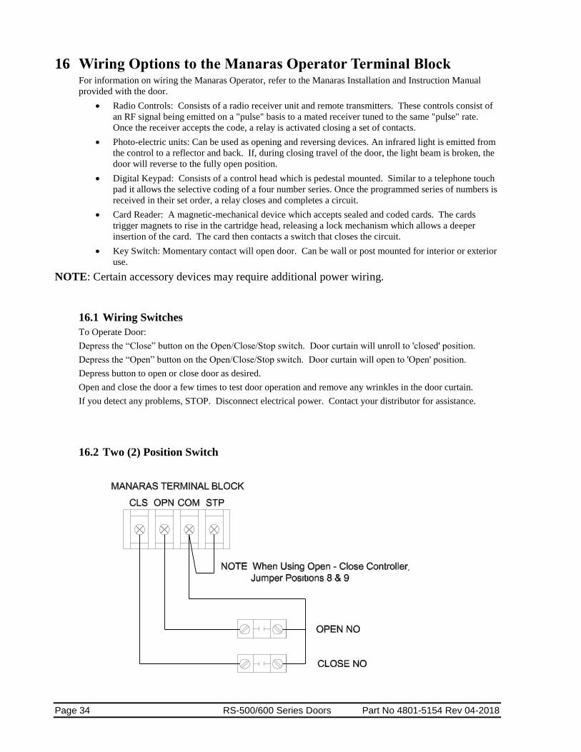
16 Wiring Options to the Manaras Operator Terminal Block For information on wiring the Manaras Operator, refer to the Manaras Installation and Instruction Manual
provided with the door.
Radio Controls: Consists of a radio receiver unit and remote transmitters. These controls consist of
an RF signal being emitted on a "pulse" basis to a mated receiver tuned to the same "pulse" rate.
Once the receiver accepts the code, a relay is activated closing a set of contacts.
Photo-electric units: Can be used as opening and reversing devices. An infrared light is emitted from
the control to a reflector and back. If, during closing travel of the door, the light beam is broken, the
door will reverse to the fully open position.
Digital Keypad: Consists of a control head which is pedestal mounted. Similar to a telephone touch
pad it allows the selective coding of a four number series. Once the programmed series of numbers is
received in their set order, a relay closes and completes a circuit.
Card Reader: A magnetic-mechanical device which accepts sealed and coded cards. The cards
trigger magnets to rise in the cartridge head, releasing a lock mechanism which allows a deeper
insertion of the card. The card then contacts a switch that closes the circuit.
Key Switch: Momentary contact will open door. Can be wall or post mounted for interior or exterior
use.
NOTE: Certain accessory devices may require additional power wiring.
16.1 Wiring Switches
To Operate Door:
Depress the “Close” button on the Open/Close/Stop switch. Door curtain will unroll to 'closed' position.
Depress the “Open” button on the Open/Close/Stop switch. Door curtain will open to 'Open' position.
Depress button to open or close door as desired.
Open and close the door a few times to test door operation and remove any wrinkles in the door curtain.
If you detect any problems, STOP. Disconnect electrical power. Contact your distributor for assistance.
16.2 Two (2) Position Switch

Part No 4801-5154 Rev 04-2018 RS-500/600 Series Doors Page 35
16.3 Three (3) Position Switch
16.4 Three (3) Position Switch With Key Lock

Page 36 RS-500/600 Series Doors Part No 4801-5154 Rev 04-2018
16.5 BEA Receiver

Part No 4801-5154 Rev 04-2018 RS-500/600 Series Doors Page 37
17 Manual Chain Hoist The Chain Hoist can be installed on left or right side of door.
The Safety Bracket is designed to lock the drive shaft (during shipping and installation) to prevent injury from rapid
drop of the door curtain. A Safety Bracket is installed on each end of the head unit. Removal of the first bracket
should only be done after door is secured to structure.
CAUTION!
Only remove the Safety Bracket from the side of the door that gets the hoist, once door is secured to wall. The Safety Bracket on the opposite side should only be removed after the hoist is installed. Removal of both Safety Brackets without hoist installed can cause
serious injury or damage.
17.1 Chain Hoist Installation
17.1.1 Removal of the First Safety Bracket
1. Remove cable tie and tag. Not shown below.
2. Remove the shaft locking hardware. See Diagram 17A, Detail B, Item 1.
3. Remove the two bolts holding Safety Bracket to Head Unit. See Diagram 17A, Detail B, Item 2.
4. Retain hardware and bracket for later use.
Safety Bracket
!
Safety bracket
Head Unit (Track and Structure not shown)
Shaft Lock
Typical – Both Ends
Detail A
Detail B
Safety Bracket Removal
1
2
Note: Cable tie and tag not
shown.

Page 38 RS-500/600 Series Doors Part No 4801-5154 Rev 04-2018
17.1.2 Chain Hoist Mechanism Installation
1. On end of door, position U-shaped mounting bracket (6421-9393) over shaft. See Diagram 17B.
2. Align bolt holes of bracket with attachment holes in door.
3. Insert bolts through cut-out openings of mounting bracket.
4. Securely attach mounting bracket to door.
5. Position Chain Hoist onto mounting bracket. Align bolt holes of hoist with holes in bracket.
6. Securely fasten Chain Hoist to bracket with bolts provided.
7. Securely attach Catch Bracket to wall with self-tapping screws provided.
8. Securely hook chain into Catch Bracket as shown below.
9. Add appropriate chain direction label from hardware kit to side
of track near the chain at a height of 4ft from the ground. Use
label 4501-9603 for chain hoists mounted on right side of door
and 4501-9602 for chain hoists mounted on left side of door.
Chain Hoist
17.1.3 Removal of Second Safety Bracket After Hoist Is Installed and Secured
1. Remove cable tie and tag. Not shown.
2. Remove the shaft locking hardware. See Diagram 17A, Detail B, Item 1.
3. Remove the bolts holding Safety Bracket to Head Unit. See Diagram 17A, Detail B, Item 2.
4. Retain hardware and bracket for later use.
Hoist installation complete.
Warning!
NEVER RELEASE CHAIN! If Chain Is Released, Door Will Drop With Rapid Motion. Injury May Occur If Chain Is Released!
1004-6021
6421-9393
Brkt.
1004-7029
Attach Catch Bracket* with two self-tapping screws (1004-0050). (*Appearance may
vary)
!

Part No 4801-5154 Rev 04-2018 RS-500/600 Series Doors Page 39
17.2 Operation of the Manual Chain Hoist
1. Carefully pull chain to open (Raise) door.
2. When door is fully raised, securely hook chain into Catch bracket as shown in Chain Hoist Instructions.
3. To Close (Lower) door, securely hold chain. Unhook chain from bracket. Gradually close door.
Caution!
NEVER RELEASE CHAIN WHILE DOOR IS BEING RAISED OR LOWERED!
You must maintain tension on chain while door is lowered to prevent rapid drop (closing) of the door.
!

Page 40 RS-500/600 Series Doors Part No 4801-5154 Rev 04-2018
18 Brother Operator
The Brother Operator will be mounted at the manufacture. Diagram 18A
shows a RS-500/600 Series Door with a Brother Operator. Refer to wiring
diagrams included in this manual and 4801-5156 RollSeal SC-325 & SC-650
Controller Manual for Brother Operator wiring.
19 Installation of RS-500/600 Series Doors Freezer Kit Installation of a RS-500/600 series Automatic Freezer Door involves connecting to the Smart
Controller SC-325 or SC-650 that connects to the AC power, the door motor, the Up/Down button,
and the safety beam, plus connecting the Condensation Management System (CMS) Unit and
associated duct work. Other accessories can be added such as a remote IR sensor, a remote radio link, and door
movement indicators such as lights and bells.

Part No 4801-5154 Rev 04-2018 RS-500/600 Series Doors Page 41
19.1 Tools Required
3/8 in. (10 mm) Power screwdriver (portable)
3/16 in. (5 mm) Drill bit and power drill
3/8 x 1 in. Bolts and nuts (supplied)
Socket
Hammer
Tape measure
Carpenter's level
NOTE: Other Tools May Be Required According To Installation.
19.2 Overview
The RS-500/600 Freezer Door is shipped with pre-assembled vertical members (left track and right tracks),
with floating magnets, and a pre-assembled horizontal member (head unit). When components are received,
check for damaged, loose or missing parts. If there are damaged or missing parts contact your RollSeal
distributor immediately. Please read and understand all instructions in this manual before beginning
installation. After the door has been assembled and attached to the door framing per instructions in Section
12, Page 18 of this manual it is necessary to install the Condensation Management System (CMS) and ducts
to complete the freezer door installation.
20 Installation of Condensation
Management System and Ducts Install the Condensation Management
System at the top of the Freezer Door
approximately in the center of the door as
shown below. Install the 5/7” Duct
Adaptor in the intake side of the
Condensation Management System.
Carefully run the duct work to the two
couplings on the left and right track of
the door. Fasten each end of the duct with
hose Clamps.
NSF Certified Doors are equipped with Left mount Brother operators,
Smart Controller, and Magnetic
Track Sealing System

Page 42 RS-500/600 Series Doors Part No 4801-5154 Rev 04-2018
20.1 Wiring the Condensation Management System for RS-500-600 Series Doors
The CMS (Condensation Management System) is designed to operate continuously.
21 Connecting Electrical Power to RS-500/600 Series Doors Refer to the appropriate Operator Manual (4801-5156 RollSeal SC-325 & SC-650 Controller Manual or the Manaras
Installation and Instruction Manual).
22 Electrical Connections for
RS-500/600 Cooler Door The Cooler Setup is designed to enable door installers to completely
install and test door operation. Electrician is still required to connect power to door, but all switch and interface
connections are made to be pluggable for ease of installation.
22.2 Connection of Controller to Head Unit.
1. Mount controller at desired location within 3’ of
junction box on Head Unit.
2. Controller has and AC and DC harness prewired
that connects to head unit as shown in Diagram
22A.
NSF Certified Doors are equipped with Left mount Brother operators,
Smart Controller, and Magnetic
Track Sealing System
Part No 4801-5154 Rev 04-2018 RS-500/600 Series Doors Page 43
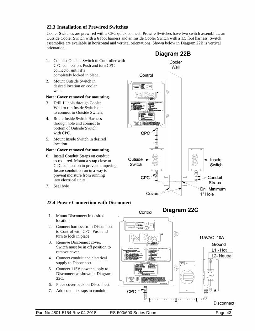
22.3 Installation of Prewired Switches
Cooler Switches are prewired with a CPC quick connect. Prewire Switches have two switch assemblies: an
Outside Cooler Switch with a 6 foot harness and an Inside Cooler Switch with a 1.5 foot harness. Switch
assemblies are available in horizontal and vertical orientations. Shown below in Diagram 22B is vertical
orientation.
1. Connect Outside Switch to Controller with
CPC connection. Push and turn CPC
connector until it’s
completely locked in place.
2. Mount Outside Switch in
desired location on cooler
wall.
Note: Cover removed for mounting.
3. Drill 1” hole through Cooler
Wall to run Inside Switch out
to connect to Outside Switch.
4. Route Inside Switch Harness
through hole and connect to
bottom of Outside Switch
with CPC.
5. Mount Inside Switch in desired
location.
Note: Cover removed for mounting.
6. Install Conduit Straps on conduit
as required. Mount a strap close to
CPC connection to prevent tampering.
Insure conduit is run in a way to
prevent moisture from running
into electrical units.
7. Seal hole
22.4 Power Connection with Disconnect
1. Mount Disconnect in desired
location.
2. Connect harness from Disconnect
to Control with CPC. Push and
turn to lock in place.
3. Remove Disconnect cover.
Switch must be in off position to
remove cover.
4. Connect conduit and electrical
supply to Disconnect.
5. Connect 115V power supply to
Disconnect as shown in Diagram
22C.
6. Place cover back on Disconnect.
7. Add conduit straps to conduit.

Page 44 RS-500/600 Series Doors Part No 4801-5154 Rev 04-2018
22.5 Preparation for Operation
Refer of the RollSeal SC-325 and SC-650 Controller Manual (4801-5156) for more information on Controller
Settings.
Note: If you detect any problems, STOP. Disconnect electrical power. Contact your
distributor for assistance.
1. Insert fuse in Control.
2. Apply 115VAC power to Control and turn Control toggle switch on.
3. Set the Open and Close Limits:
1. Depress the Mode button (●) for at least 5 seconds. P1 (Close Time Delay) will be then be
displayed in the Display Indicator.
2. Depress and release the Mode button until PS1 (Change Program Limits) is displayed.
3. Depress Up ( ) until “yes” is displayed.
4. Depress the Mode button again (●). PS2 (Set Open Limit) will be displayed.
5. The door will proceed to the open limit and then stop. Once the door stops, adjust open limit
using the Up ( ) or Down ( ) buttons until open limit is satisfactory.
6. Depress the Mode button (●) again. PS3 (Set Closed Limit) will be displayed.
7. The door will proceed to the closed limit and then stop. Once door stops, adjust this limit using
the Up ( ) or Down ( ) buttons until the close limit is satisfactory.
8. Depress the Mode button (●) again and the controller will exit the programming mode and return
to displaying the actual position.
4. Press “Open” button on Outside Switch. If the Door is set to automatically close, door will time out
and automatically close if safety beams are clear. If the Door is set to manually close, press “Close”
button on Outside Switch and door should close.
5. Press “Open” (and “Close” if required) a couple times to insure proper operation.
6. Repeat steps 4 and 5 for Inside Switch.
7. Verify Safety Beams reverse door when blocked during closing.
8. Verify Leading Edge Switch is operational.
9. Verify that Warning Light and Egress Buzzer (if applicable) are functioning properly.
10. Ensure Safety Pull Hook for Egress and Pull Hook Tether are mounted inside cooler and Manual
Crank Handle for motor is mounted outside.
The door is now ready for operation.

Part No 4801-5154 Rev 04-2018 RS-500/600 Series Doors Page 45
23 Operation of RS-500/600 Series Doors With Brother Operator NOTE: Refer to the RollSeal SC-325/650 Controller
Manual for wiring and initial setup. After
wiring the controller to the door, connect
electrical power to the controller. The
door is now ready for operation.
The controller keeps track of the "open" and "closed" positions of the door by means of a mechanical encoder wheel
that is located in the encoder box. The controller electronically counts steps as the wheel turns to keep track of the
door position. The door seals by means of 'hook & loop’ or ‘magnetic’ strips along the edges of the door curtain and
vertical members.
23.1 Operation of a Standard RS-500/600 Series Door:
1. Depress “Open” switch button mounted on the wall. Door curtain will roll up to 'open' position and find
“HOME” position and drop some to the set upper limit. If door was wired for “timer” it will count down
from set delay and close on its own. If not on wired on “timed” function proceed to step 2 to close.
2. Depress “Close” switch button. Door curtain will roll down to 'closed' position of lower limit and stay
3. Depress button to open or close door as desired.
4. Open and close the door a few times to test door operation and remove any wrinkles in the door curtain.
If you detect any problems,
STOP.
Disconnect electrical power.
Contact your distributor for
assistance.

Page 46 RS-500/600 Series Doors Part No 4801-5154 Rev 04-2018
23.2 Operation of RS-500/600 Series Door with
Optional Freezer Kit
1. Depress “Open” switch button mounted on the wall.
Door curtain will roll up to 'open' position and find “HOME”
position and drop some to the set upper limit. If door was wired for “timer” it will count down from set
delay and close on its own. If not on wired on “timed” function proceed to step 2 to close.
2. Depress “Close” switch button. Door curtain will roll down to 'closed' position of lower limit and stay
3. Depress button to open or close door as desired.
4. Open and close the door a few times to test door operation and remove any wrinkles in the door curtain.
*Refer to the 4801-5156 SC-325 and SC-650 product manual for additional smart controller information.
PROGRAM PARAMETERS
P1 - Close Time Delay (Seconds)
P2 - Acceleration Range
P3 - Deceleration Range
P4 - Door Interlock
0 – Off or Optional Door Motion
Light(s)/Buzzer(s)
1 - Sequential Interlock
2 - Passive Interlock
3 – Freezer Mode - No Interlock
P7 - Refresh Door Limits
P10 - Service Cycle Reset
0 - No
1 - Yes
P11 - Service Reminder (Cycles x 100)
P12 - Input Status
PS1 - Set Limits?
PS2 - Set Open Limit
PS3 - Set Close Limit
24 Limit Switches There are three limit switches located within the horizontal member mechanism. See Diagram 24A. These
switches are attached to levers that contact the curtain.
The Home Switch
establishes the 'open'
reference position of the
door curtain. This creates
the zero reference
position, from which the
encoder counts the
position of the door.
The Safety Switch is a fail-
safe switch that stops the
curtain in the unlikely
event of malfunction of
the home switch.
The Leading Edge Switch is
a switch that stops the
curtain in the event of a
doorway obstruction.
NSF Certified Doors are equipped
with Left mount Brother operators,
Smart Controller, and Magnetic Track Sealing System
Part No 4801-5154 Rev 04-2018 RS-500/600 Series Doors Page 47
25 Manual Operation RS-500/600 Series Door
With Brother Operator
The RS-500/600 Series Door can be operated manually in the event of a power outage or if there is a motor
malfunction. To operate the door manually, perform the following instructions.
Warning!
Disconnect All Electrical Power To Motor Before Attempting To Operate The Door Manually!
Warning!
The Curtain Is Released When Brake Lever Is Disengaged. Do Not Disengage Brake Until Door Opening Is Clear!
If door is OPEN (door curtain raised) perform the following steps:
1. Locate brake lever at bottom of motor. (See diagram below).
2. Carefully release brake by flipping lever down.
CAUTION: Curtain will drop when brake is released.
If door is CLOSED (door curtain lowered) perform the following steps:
1. Turn power off to the controller
2. Locate brake lever at bottom of motor.
3. Carefully release brake by flipping lever down.
4. Motor shaft is accessible from bottom of
motor. Use provided Crank Handle to
rotate motor shaft.
5. Carefully turn motor shaft
counterclockwise to raise door
curtain.
Note: The drive (as viewed
from the 'motor end' of door) is
counterclockwise rotation of the motor
shaft.
5. When door curtain has
been raised
to desired height, flip
brake lever
up to engage brake.
6. If you do not release the
brake it could result in
damage to the motor.
!
!

Page 48 RS-500/600 Series Doors Part No 4801-5154 Rev 04-2018
26 Adjustment of Brake (Brother Motor Only) After extended operation of the brake lever, the brake may become worn. As the brake wears, some adjustment to
the brake is required. Lettered diagrams below correspond to lettered instructions. Follow instructions to adjust
brake:
1. Close door curtain to fully lowered position.
2. Engage Brake lever.
3. Disconnect electrical power to motor.
4. Remove four Phillips screws (A).
5. Remove cover (B).
6. Straighten the bent tab (C) of spider nut.
7. Tighten spider nut (C) snuggly against
blower wheel. Make sure a tab of spider
nut is aligned with a notch in the shaft
8. Bend tab (C) upward into notch of shaft.
9. Replace cover (B).
10. Replace four Phillips screws (A).
11. Disengage brake lever (D).
12. Adjustment complete.

Part No 4801-5154 Rev 04-2018 RS-500/600 Series Doors Page 49
27 Door Panel Adjustments
During normal operation, the tension pipes should run in close proximity of each other. The clearance between the
tension pipes should normally be between 1/4 to 1/2 (6.35 mm - 12.7 mm). See Detail 3 below. There are two
situations pertaining to the tension pipes that may cause problems with door operation. If the tension pipes are too
far apart, the tension pipes will not repel each other. This causes poor contact between the hook & loop or
magnets. On the other hand, if the tension pipes are riding one another (i.e. touching one another), the door panel
material does not flow evenly, thus leaving wrinkles in the panel instead of a stretched, smooth & even appearance.
Adjustment Procedures
The clearance between the tension pipes can be adjusted by raising or lowering the door panels. Each door has three
panels: (1) the inside panel (panel facing the inside of building) is attached to the back plate. (2) The center panel is
attached to the roller. (3) The outside panel (facing the outside of building) is attached to the front bar. Adjustments
are made to the inside panel and/or the outside panel.
NOTE: The door must be in the closed position for panel adjustments. Ensure the
panels are not damaged while removing or reinstalling the nuts and screws.
To adjust the height of the outside tension pipe, raise or lower the outside door panel by detaching the panel hook &
loop from the front bar, and raising or lowering the panel. Then re-attach the panel loop to the hook on the front bar.
Be sure to keep the tension pipe level during this procedure.
To adjust the height of the inside tension pipe, raise or lower the inside door panel by detaching the panel hook &
loop from the back plate, and raising or lowering panel. Then re-attach the panel loop to the hook on back plate. Be
sure to keep tension pipe level during this procedure. Install Tek screws through the panel material and into the
back plate to securely hold the material in place.

Page 50 RS-500/600 Series Doors Part No 4801-5154 Rev 04-2018
28 Removal of Existing Panel 1. Lower the panel to the floor.
2. Locate the door controller and turn off the power.
3. Remove and lower the cover from the door head unit.
4. Locate the 3 fabric sheets that make up the entire door curtain. See Diagram 29A, Detail 2, Page 51. The
center panel has a hook & loop strip across the top. The center panel does not have magnets or hook & loop
strips on the sides. The inside and outside panels have hook & loop strips at the top, and magnets or hook &
loop strips along the sides of the panels. The outside panel may be identified as the longer of the two panels.
5. Mark the end of each sheet and along the edge of each sheet with a marker. This will prove vital to ensure
you install the new panel sheets at the proper locations to alleviate major curtain adjustment.
6. Remove the 3 screws from each sheet (front, center, and back). See Diagram 29A, Detail 2, Page 51. Detach
the hook & loop area of each sheet left to right, starting with front, then center, and then back sheets. Let the
panel/curtain fall to the floor.
NOTE: If the door is equipped with an egress assembly you will see the yellow egress
strap attached to a triangle piece of material with a quick-link connector. If it does
not have this strap, read the notes below and proceed to step 8.
7. UN-screw the quick-link connector and allow the panel to lower to the floor.
NOTE: Observe how the tension pipes are installed before removal. They MUST be re-
installed first, with one pipe in the front/outer pocket (closest to outside of the cooler)
and the other pipe in the back/inside pocket. Locate the back pipe behind the
triangle piece that is attached to the yellow strap. The front/outer pipe will always
hang lower than the back/inside pipe.
NOTE: Failure to install properly could result in door sticking up.
8. Slide the 2 tension pipes out of their respective pockets. Remove the panel/curtain away from the door. You are
now ready to install the new panel/curtain.
29 Installation of Replacement Panel
1. Place the new panel in front of the door opening and make sure the part number label is on the left side.
NOTE: If door is equipped with egress system yellow strap ensure that the strap is
positioned to the front side of the back/inside panel to allow connection to the triangle
piece of material with the quick-link connector.
2. Take the back/inside curtain (Diagram 29A, Detail 1 & 2, Page 51) and attach the material to the
backplate placing material on the marks that were created during removal of old panel.
3. After the inside curtain has been attached, attach the egress strap (if equipped) to the triangle piece of
material with the quick link connector.
4. Take the middle curtain (Diagram 29A, Detail 1 & 2, Page 51) and attach to the drive pipe.
5. Take the outside curtain (Diagram 29A, Detail 1 & 2, Page 51) and attach to the top bar.
NOTE: Ensure all roller switches (home, safety and leading edge) are pointing down.
6. After the curtain has been secured, install the bottom pipes in the curtain as shown in Diagram 29A, Detail
3, Page 51. The front pipe should be installed first. Then the back pipe is placed in front of inside panel but
behind the yellow strap and triangle piece of material. It should be above the front pipe.
7. Ensure all panels are inside the tracks on both sides. Turn controller on and set to JOG mode by holding
both arrows at the same time until you see “JOG” on the display. JOG up and down, using up and down
arrows to straighten the panel. Exit JOG mode by holding both arrows at the same time. Run the door as
normal.

Part No 4801-5154 Rev 04-2018 RS-500/600 Series Doors Page 51
Curtain Installation

Page 52 RS-500/600 Series Doors Part No 4801-5154 Rev 04-2018
30 Cleaning Panels and Windows Panels and Windows can be cleaned using a solution of cold to warm, mild soapy water and a cloth.
Wipe off the soiled area to remove dirt particles. Using a cloth gently wipe the panel and window with the soapy
solution. Thoroughly rinse the area with pure cold or warm water to remove soap.
Dry off thoroughly with a dry cloth. DO NOT ROLL-UP the panel onto itself without making sure
it is completely dry!!!
DO NOT USE: Solvents or strong alkaline cleaners. Use of these products could cause damage.
If in doubt about a particular cleaning solution, please do not hesitate to contact customer service for our
recommendation.
31 Optional Door Features 31.1 Warning Indicator Light (Optional Feature)
Any time the cooler door is opening or closing, this light will flash indicating movement of door.
Note: On the SC-325 and SC-650, P4 setting in program mode must be set to 0 for proper operation.
Note: This feature will not work on Interlock or Freezers using CMS unit.
31.2 Egress Strap (Optional Feature) The Emergency Egress feature provides a simple and convenient way to open door in emergency situation from
inside the cooler should the door motor become inoperative due to a power failure or other conditions. The
Emergency Egress Strap is located at center top of door. The door is opened by using the Emergency Egress Tool to
hook D-Ring and pull strap down. Strap may be pulled by hand also. As strap is pulled, the door will open up
enough that person can exit cooler safely.
31.3 Egress Buzzer (Optional Feature) In the event the Egress Strap has been pulled, a buzzer will sound from the Head Unit as long as door has power. To
turn buzzer off, the egress strap must be fully reset.
See Section 32.3 for information on re-setting the Egress Strap.
31.4 Soft Tension Pipes (Optional Feature) Soft Tension Pipes are designed to reduce or eliminate injury from impact of tension pipe. Available as an optional
feature, existing doors can be upgraded. The pipe design helps to insure proper sealing of the door. Soft Tension
Pipes are available for door sizes up to 10 feet.
31.5 Impact Resistant Tension Pipes (Optional Feature) The Impact Resistant Tension Pipe is more flexible than our standard Tension Pipe. Impact Resistant Tension Pipes
are available for door sizes up to 12 feet.

Part No 4801-5154 Rev 04-2018 RS-500/600 Series Doors Page 53
Diagram 32A
Diagram 32B Diagram 32C
32 Emergency Egress (Optional Feature) The Emergency Egress feature provides a simple and convenient means of exiting a Roll Seal RS-500 Door from the
inside of the structure should the door motor become inoperative due to a power failure or other conditions.
32.1 Installation
Install the Egress Tool Retainer (1040-8400) to the left or right side outside of door jamb. For a wood framed
door jambs use #10 x1 screw (1004-1386). For a metal framed door jamb use #8x1/2 Tek screw (1004-
2492). See Diagram 32A.
The Egress Tool Tether (1040-8401) provides a means of attaching the egress hook to a location on the wall
to prevent loss of the egress hook. This tether provides up to eight feet of cable. It can be mounted anywhere
necessary to allow reach, hook, and pull of the Egress D-ring. The tether can be used on doors up to 10’ x 10’.
Attach the Tether with four (4) ¼” phillips screws (1004-2068).
32.2 Exiting (Opening) The Door
1. Remove Emergency Egress Tool from the retainers on the
side of the door.
2. Connect the hook end of the tool to the
D-Ring on the top of the door frame.
See Diagram 34B and Diagram 34C.
3. Pull down on the Egress Strap. The Door will raise
approximately half way up. The door will open enough for
a person to exit the structure. See Diagram 32D.
Install the Emergency Egress Tool Retainer
on the door jam
Cam Buckle
Egress Strap
D-ring
Egress Tool
Egress Tether
Egress Retainer

Page 54 RS-500/600 Series Doors Part No 4801-5154 Rev 04-2018
NOTE: The Release for the
Cam Buckle is located on
the panel side of the
Buckle. This view shows
the Cam Buckle as see
from the front of the door.
32.3 Resetting (Closing) The Door
After the RollSeal RS-500 Door is opened by using the Emergency Egress Strap, the door must be carefully
re-set to ensure proper operation in the future.
1. Firmly hold strap. See Diagram 32F.
2. Press the Cam Buckle Release. See Diagram 32G.
3. Gradually feed strap through Cam Buckle until door is closed at bottom and D-ring is in the
position shown in Diagram 32E.
4. Return Emergency Egress Tool to retainer for future use.
5. Cycle the door up and down in normal operating mode to ensure proper re-setting of the door.
Adjust if necessary. Door should now function normally.
Diagram 32E
CAUTION!
When the Cam Buckle is released, the door will rapidly close unless tension is held on the strap. Keep fingers away from buckle while closing.
!
Firmly hold strap.
Cam Buckle
Egress Strap
D-ring
Egress Tool
Cam Buckle Release
NOTE: This view
shows the Cam
Buckle as seen
from the back of
the door when the
Egress Strap has
not been pulled.

Part No 4801-5154 Rev 04-2018 RS-500/600 Series Doors Page 55
33 Egress Strap Removal/Re-Installation
33.1 Removal
1. Remove the door’s head unit cover
2. Locate the door controller. Place the door in the JOG mode by holding the Up and Down arrows on
the controller at the same time until you see “JOG” in the controller’s display.
Warning!
Failure to stop the door when nearing the full open or full close position can cause damage to the door components.
3. Watch the panel closely while slowly jogging/rolling the curtain up on the drive shaft. Stop the door
when you find the area where the quick-link attaches the long yellow Egress Strap loop to the yellow
strap loop of the triangle panel piece.
4. Turn off the power switch located on the left side of the controller.
5. Unscrew the quick-link. Make sure not to drop the counter-weight into the door.
6. Access the inside area of the cooler/freezer box through the door opening. If the strap is hanging
inside, carefully remove the Egress Strap (top center of door) from the door. Remove the gold cam
buckle.
33.2 Installation
1. Ensure power has been turned off to the controller.
2. Un-roll the new yellow Egress Strap with attached gold cam buckle.
3. From the outside area, locate the roller assembly at the top center of the door where the original strap
came into the curtain area from the inside cooler/freezer area. Use anything with some stiffness
(banding material) and feed the stiff item through the roller and down through the slot located in the
inside cooler/freezer area and tape or tie it to the small loop (not the D-ring) of the yellow strap.
Gently pull it through the hole and roller assembly at the top/center of the door.
4. Ensure the yellow strap is not twisted. Place the counter-weight onto the yellow strap.
5. Attach the new strap loop to the yellow strap loop on the triangle panel piece using the quick-link.
6. Attach the new gold cam buckle to the door frame.
7. Turn the controller on and return to JOG mode, use the down arrow to lower the door to the floor.
Exit JOG mode by holding the Up and Down arrows on the controller at the same time until you see
“---” in the display of the controller.
8. Press “Open” button. If the Door is set to automatically close, door will time out and automatically
close (if safety beams are clear). If the Door is set to manually close, press “Close” button and door
should close.
Note: If the door does not lower to the Closed position, see 32.3 Resetting (Closing) The
Door.
Note: If you detect any problems, STOP. Disconnect electrical power. Contact your
distributor for assistance.
9. Press “Open” (and “Close” if required) several times to insure proper operation.
10. Re-attach the cover.
!

Page 56 RS-500/600 Series Doors Part No 4801-5154 Rev 04-2018
34 Removing and Replacing Floating Magnets or Velcro
NOTE: The door shown in the following illustrations may have different options and accessories than your
door. Removing and replacing the floating is the same for all RollSeal units.
Diagram 34A
1. Turn off controller or remove power to
the door.
2. Open the door to its upper limit. It
will be necessary to raise the panel as
high as it will go into the head unit.
Refer to the appropriate Operator
Manual (4801-5156 RollSeal SC-325
& SC-650 Controller Manual or the
Manaras Installation and Instruction
Manual). This will make it easier for
you to remove and re-install the
“Floating Magnets or Velcro and PIM
Plate Assemblies” from the left and
right side tracks (Diagram 34A).
Warning!
Ensure power is turned “OFF” to prevent door movement while removing PIM Plate Assembly and Floating!
Ensure panel is raised into the head unit.
!

Part No 4801-5154 Rev 04-2018 RS-500/600 Series Doors Page 57
2. After you have raised the panel into the head unit, you can remove all of the PIM Plate nuts from both sides.
Then remove the PIM plate and floating assemblies from their associated tracks (Diagram 34B and Diagram
34C).
Note: NSF Certified doors are equipped with a black rubber boot that covers the
PIM bolts. Remove the black rubber boots to access the PIM nuts. Place
the boots in a secure location for they must be replaced onto the PIM bolts
after the Floating has been replaced.
Diagram 34B Diagram 34C
Squeeze the floating around the PIM Plate and pull the PIM plate assembly and floating out away from the track assembly.
Remove all the PIM nuts from top to bottom

Page 58 RS-500/600 Series Doors Part No 4801-5154 Rev 04-2018
3. Lay the PIM plate assembly down on the floor and remove the old floating material from the PIM plate.
Pay particular attention to the top of the PIM plate assembly. You will notice the material, at the top, has
been cut at an angle. It will be necessary to re-install the new piece in the same arrangement as the one you
have removed (Diagram 34D and Diagram 34E). Get the new piece of floating material. Flip the new
piece upside down with the magnets or Velcro toward the floor. Align the pre-drilled holes of the material
with the PIM bolts on the PIM plate assembly. You might find it easier to start at one end with the first PIM
bolt, insert it, and then move to the other end slightly lifting the PIM plate in a bend to insert the PIM bolt
at that end (Diagram 34F). Lay the assembly back down on the floor flat. This will slightly pull the
material allowing the remaining holes to align properly. Proceed to insert the rest of the PIM bolts in their
proper holes. Repeat the same steps for installing the floating to PIM plate for the other side.
Diagram 34D
Diagram 34E
Diagram 34F
Lay the new floating next to the PIM plate with top of floating (Angled Cut) material to top of PIM plate. Flip the floating over the PIM Plate with magnets or Velcro against the floor then attach the floating over the PIM Plate Bolts
Remove the “old” floating and discard. Re-install the “new” floating
Re-install the “new” floating. It may be necessary to bend one end of the PIM plate up to attach onto the end PIM bolt.
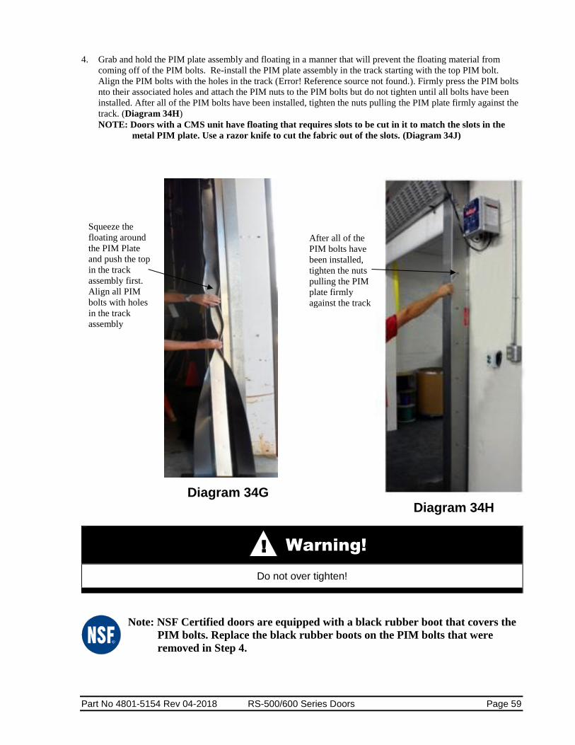
Part No 4801-5154 Rev 04-2018 RS-500/600 Series Doors Page 59
4. Grab and hold the PIM plate assembly and floating in a manner that will prevent the floating material from
coming off of the PIM bolts. Re-install the PIM plate assembly in the track starting with the top PIM bolt.
Align the PIM bolts with the holes in the track (Error! Reference source not found.). Firmly press the PIM bolts
nto their associated holes and attach the PIM nuts to the PIM bolts but do not tighten until all bolts have been
installed. After all of the PIM bolts have been installed, tighten the nuts pulling the PIM plate firmly against the
track. (Diagram 34H)
NOTE: Doors with a CMS unit have floating that requires slots to be cut in it to match the slots in the
metal PIM plate. Use a razor knife to cut the fabric out of the slots. (Diagram 34J)
Diagram 34G Diagram 34H
Warning!
Do not over tighten!
Note: NSF Certified doors are equipped with a black rubber boot that covers the
PIM bolts. Replace the black rubber boots on the PIM bolts that were
removed in Step 4.
Squeeze the
floating around
the PIM Plate
and push the top
in the track
assembly first.
Align all PIM
bolts with holes
in the track
assembly
After all of the
PIM bolts have
been installed,
tighten the nuts
pulling the PIM
plate firmly
against the track
!
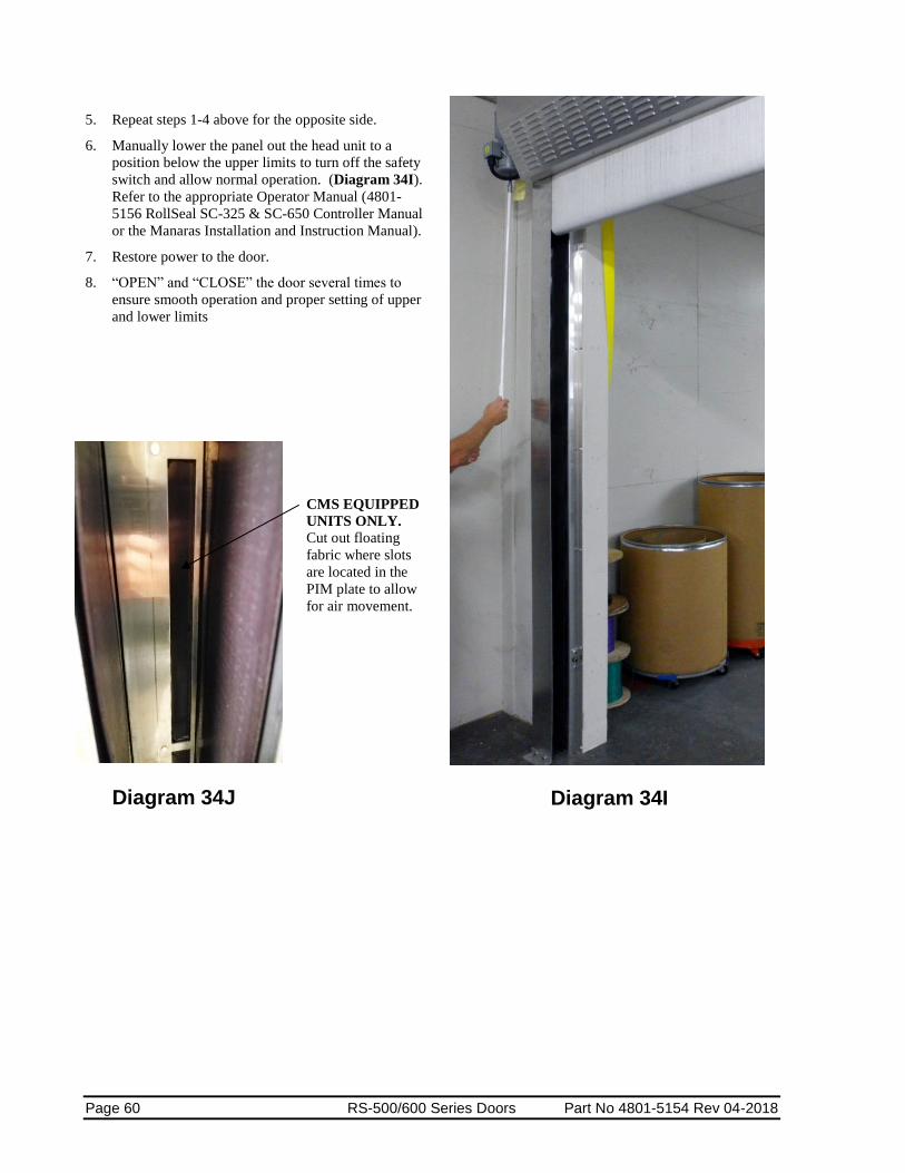
Page 60 RS-500/600 Series Doors Part No 4801-5154 Rev 04-2018
5. Repeat steps 1-4 above for the opposite side.
6. Manually lower the panel out the head unit to a
position below the upper limits to turn off the safety
switch and allow normal operation. (Diagram 34I).
Refer to the appropriate Operator Manual (4801-
5156 RollSeal SC-325 & SC-650 Controller Manual
or the Manaras Installation and Instruction Manual).
7. Restore power to the door.
8. “OPEN” and “CLOSE” the door several times to
ensure smooth operation and proper setting of upper
and lower limits
Diagram 34I
Diagram 34J
CMS EQUIPPED
UNITS ONLY.
Cut out floating
fabric where slots
are located in the
PIM plate to allow
for air movement.
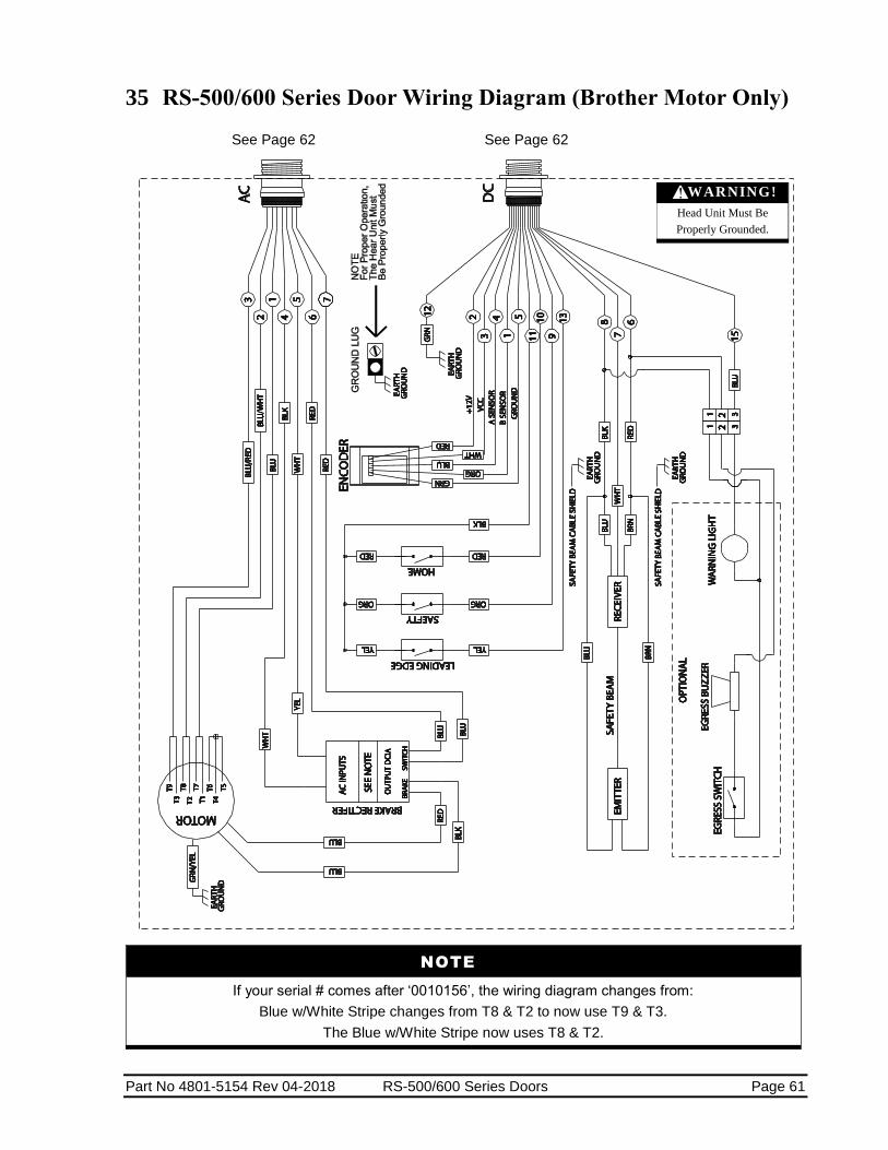
Part No 4801-5154 Rev 04-2018 RS-500/600 Series Doors Page 61
35 RS-500/600 Series Door Wiring Diagram (Brother Motor Only)
See Page 62 See Page 62
NOTE
If your serial # comes after ‘0010156’, the wiring diagram changes from:
Blue w/White Stripe changes from T8 & T2 to now use T9 & T3.
The Blue w/White Stripe now uses T8 & T2.
WARNING!
Head Unit Must Be
Properly Grounded.

Page 62 RS-500/600 Series Doors Part No 4801-5154 Rev 04-2018
36 RollSeal Smart Controller Wiring Diagram
(Brother Motor Only)
See Page 56 See Page 56

Part No 4801-5154 Rev 04-2018 RS-500/600 Series Doors Page 63
37 SC-325 Wiring Diagram

Page 64 RS-500/600 Series Doors Part No 4801-5154 Rev 04-2018
38 RollSeal CMS (Condensation
Management System) Wiring
Diagram
NSF Certified Doors are equipped
with Left mount Brother operators,
Smart Controller, and Magnetic Track Sealing System

Part No 4801-5154 Rev 04-2018 RS-500/600 Series Doors Page 65
39 Wiring Optional Accessories Motion Detectors, Infrared Sensors and Loop Sensors are optional accessories that can improve the efficiency
and performance of your RollSeal Door. Sensors can also help prevent damage to the RollSeal Door by
preventing the door from closing while lifts or objects are present in the vicinity.
Refer to the unit Owner’s Manual for more information on installation, set-up and operation.
39.1 Wiring Falcon XL and EX Motion Detectors
39.2 Wiring Falcon IS40 Infrared and Microwave Sensor
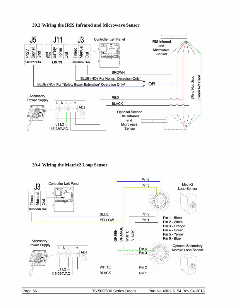
Page 66 RS-500/600 Series Doors Part No 4801-5154 Rev 04-2018
39.3 Wiring the IRIS Infrared and Microwave Sensor
39.4 Wiring the Matrix2 Loop Sensor
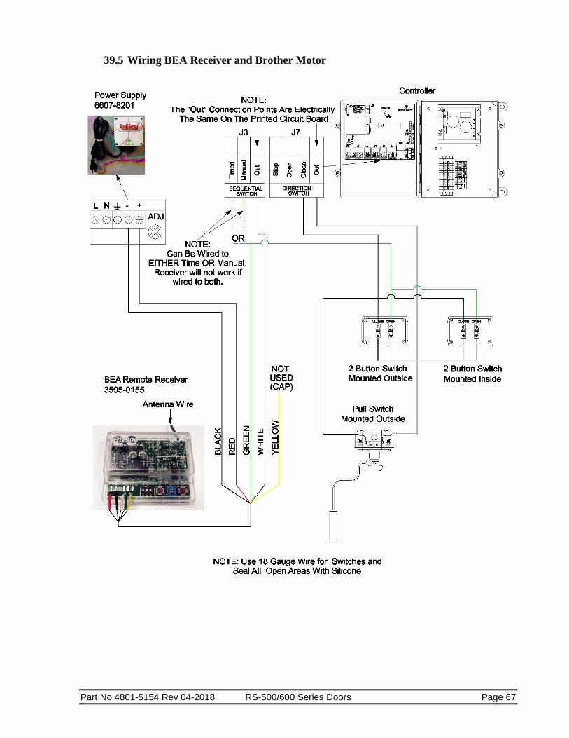
Part No 4801-5154 Rev 04-2018 RS-500/600 Series Doors Page 67
39.5 Wiring BEA Receiver and Brother Motor

Page 68 RS-500/600 Series Doors Part No 4801-5154 Rev 04-2018
40 Replacement Parts and Optional Accessories
40.1 SC-325 Controller
SC-325 Controls, Parts, and Accessories
Part Number Description Notes
Controller
6607-8057 SC-325-V01-115 Use with RS-500 Doors ONLY
6607-8056 SC-325-V02-0 (Includes V2 Drive & Brake Module) Use with RS-500 Doors ONLY
6607-8058 SC-325-V01-000-W01 (Includes W01 Switch Wiring Option with Conduit)
Use with RS-500 Doors ONLY
6607-8060 SC-325-V01-115-PLUS (Includes Prewired Controller) Use with RS-500 Doors ONLY
6607-8061 SC-325-V01-230-PLUS (Includes Prewired Controller) Use with RS-500 Doors ONLY
Drive Board Assemblies
6407-6082
Use with SC-325 Controller 6607-8057, 6607-8058, 6607-8060, and 6607-8061
/PCB AC DriveKBVF-22D w/QA V1 (V1 Drive)
Use with SC-325 Controllers ONLY.
6407-6083 Use with SC-325 Controller 6607-8056
/PCB AC DriveKBVF-22D w/QA V2 (V2 Drive) Use with SC-325 Controllers ONLY.
1902-4701 Drive Cable Assembly
Chips
3701-6069 PIC SC-325 RS Door Control V0.xx (Processor) Use with SC-325 Controllers ONLY.
3540-0143 Double ‘E’ Chip
Fuses
3010-3001 FUSE 1.2 AMP 5mmX20mm slow blow (F1) Located on PCB 154
3010-2140 FUSE 10 AMP 1/4X1-1/4 TD Main Fuse (Black Holder) Use with SC-325 Controllers ONLY.
Brake Module & Rectifier
6407-6088 Brake Module (Use with SC-325 Controller 6607-8056)
3017-5052 Brake Rectifier (Use with 115 VAC Doors)
3017-5050 Brake Rectifier (Use with 230 VAC Doors)
Switches
3001-2865 Main Power Switch w/toggle tabs
Door Assembly
6407-0618 /DOOR ASSY SC-325 Use with SC-325 Controllers ONLY.
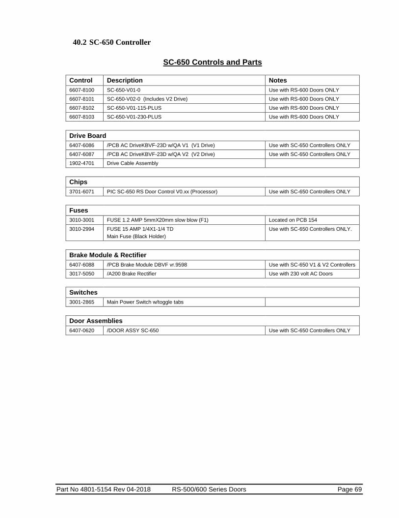
Part No 4801-5154 Rev 04-2018 RS-500/600 Series Doors Page 69
40.2 SC-650 Controller
SC-650 Controls and Parts
Control Description Notes
6607-8100 SC-650-V01-0 Use with RS-600 Doors ONLY
6607-8101 SC-650-V02-0 (Includes V2 Drive) Use with RS-600 Doors ONLY
6607-8102 SC-650-V01-115-PLUS Use with RS-600 Doors ONLY
6607-8103 SC-650-V01-230-PLUS Use with RS-600 Doors ONLY
Drive Board
6407-6086 /PCB AC DriveKBVF-23D w/QA V1 (V1 Drive) Use with SC-650 Controllers ONLY
6407-6087 /PCB AC DriveKBVF-23D w/QA V2 (V2 Drive) Use with SC-650 Controllers ONLY
1902-4701 Drive Cable Assembly
Chips
3701-6071 PIC SC-650 RS Door Control V0.xx (Processor) Use with SC-650 Controllers ONLY
Fuses
3010-3001 FUSE 1.2 AMP 5mmX20mm slow blow (F1) Located on PCB 154
3010-2994 FUSE 15 AMP 1/4X1-1/4 TD
Main Fuse (Black Holder)
Use with SC-650 Controllers ONLY.
Brake Module & Rectifier
6407-6088 /PCB Brake Module DBVF vr.9598 Use with SC-650 V1 & V2 Controllers
3017-5050 /A200 Brake Rectifier Use with 230 volt AC Doors
Switches
3001-2865 Main Power Switch w/toggle tabs
Door Assemblies
6407-0620 /DOOR ASSY SC-650 Use with SC-650 Controllers ONLY

Page 70 RS-500/600 Series Doors Part No 4801-5154 Rev 04-2018
40.3 Door Replacement Parts and Accessories
RollSeal Parts, and Accessories
Part Number Description Notes
Cable and Harness Assemblies
1903-3053 HRNS RS-500 and RS-600 DC
1903-3016 HRNS RS-500 and RS-600 AC
1903-3064 HRNS RS-500 DC (Short)
1903-3063 HRNS RS-500 and RS-600 AC (Short)
1902-4701 Drive Cable Assembly
Encoder
6407-1565 Encoder Board
6421-1404 Encoder Assembly
6450-2008 Encoder Bracket Kit
Safety Beam
6421-9040 Emitter (motor side)
6421-9041 Receiver
Door Switches
1903-3050 Safety Switch
1903-3051 Leading Edge Switch
1903-3052 Home Switch
Door Replacement Parts
0401-7728 Leading Edge Switch Bracket
Power Supply and BackUp Units
3595-0109 Power BackUp 115 VAC
6607-8200 Accessory Power Unit 12VDC 4.5A
6607-8201 Accessory Power Unit 12VDC 1A
6607-8202 Battery BackUp 230VAC 850VA
6607-8203 Battery BackUp 115VAC
Motion Detectors and Sensors
3595-0108 Falcon XL 3595-0103
3595-0006 Falcon EX 3595-0104
3595-0127 Falcon IS40
3595-0125 IRIS
3595-0110 Matrix2
Terminal Blocks
3006-5076 2 Position Terminal Block
3006-5077 3 Position Terminal Block
3006-5078 4 Position Terminal Block
3006-5079 5 Position Terminal Block
3006-2984 2 Pin Mini Jumper
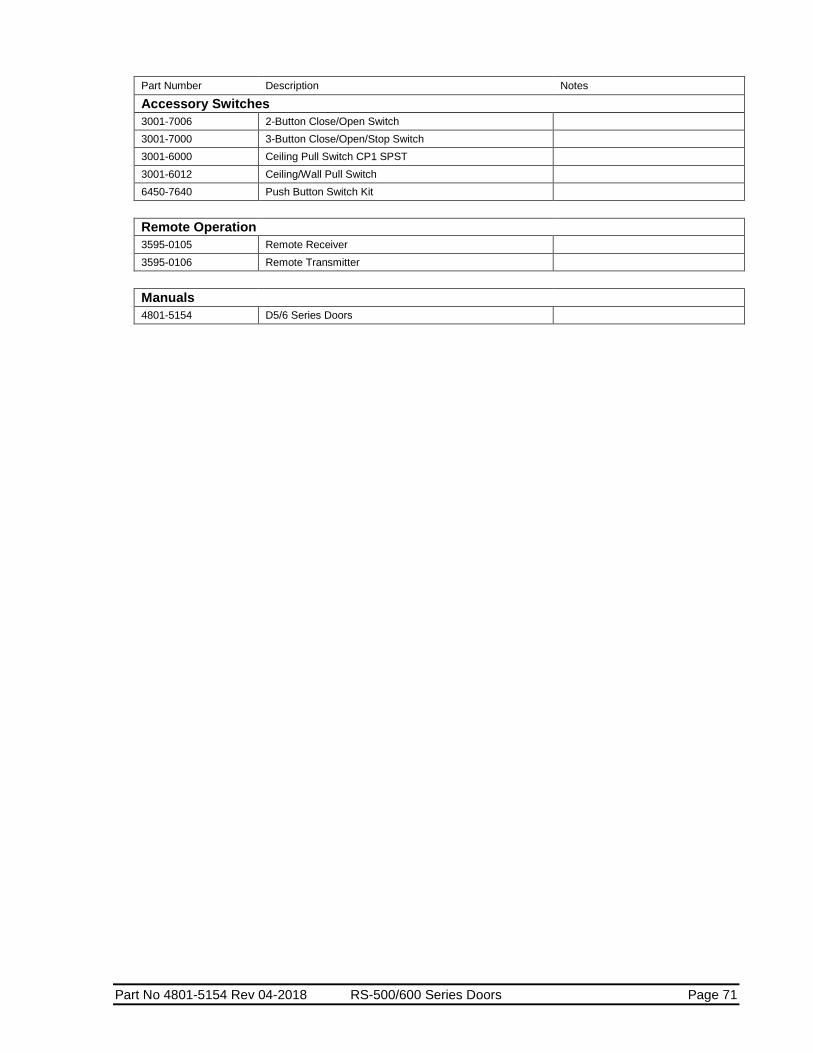
Part No 4801-5154 Rev 04-2018 RS-500/600 Series Doors Page 71
Part Number Description Notes
Accessory Switches
3001-7006 2-Button Close/Open Switch
3001-7000 3-Button Close/Open/Stop Switch
3001-6000 Ceiling Pull Switch CP1 SPST
3001-6012 Ceiling/Wall Pull Switch
6450-7640 Push Button Switch Kit
Remote Operation
3595-0105 Remote Receiver
3595-0106 Remote Transmitter
Manuals
4801-5154 D5/6 Series Doors

Page 72 RS-500/600 Series Doors Part No 4801-5154 Rev 04-2018

Part No 4801-5154 Rev 04-2018 RS-500/600 Series Doors Page 73