Embed Size (px)
Citation preview
RPS GROUP OF INSTITUTIONS,
BALANA
MOHINDERGARH
LAB MANNAUL
_____________ PC LAB _______________
CSE 3rd SEM
Department of Computer Science and Engineering
2015-16
PC Lab
Code: IT-201 F
L T P Class Work: 50
- - 2 Exam: 50
Total: 100 Duration of Practical:3 Hrs.
Syllabus for lab Work:--
PC Software: Application of basics of MS Word 2000, MS Excel 2000, MS Power Point 2000, MS Access 2000.
1.Introduction of basic elements of Microsoft Word.
2. To Study Microsoft Excel.
3. To Study Microsoft power point .
4. To Study Microsoft Access.
PC Hardware :
5. To Identifying external ports and interfacing of PC.
6.To make comparative study of motherboards.
7.To study various cards used in a system viz. display card, LAN card etc.
8.To remove, study and replace floppy disk drive.
9.To remove, study and replace hard disk.
10.To remove, study and replace CD ROM drive.

Hardware and Software requirement
Software Requirements:
Software : M.S.Office-2003,2007
Hardware Requirement:
Processor : 386 and above
RAM : 16 MB
HDD Space : 8 MB
H/W Parts : Display card, LAN card, floppy disk drive,
Hard disk, CD ROM Drive, keyboard and mouse
Monitor,Drivers, Memory and printers,Motherbord

Objectives:-
The aim of this course is to provide an introduction to computer Parts and computer
Software Basics with an emphasis on foundational material
Outlines:- At the end of the course students should
• have a good understanding of Hardware Parts of Computers.
• have a good understanding of the fundamental concepts of Computer
Organization
• be able to Work on M.S Office(MS Word 2007, MS Excel 2007, MS Power Point
, MS Access).
• be able to Solve Mathematical Problems and Database Problems with the help of
computer.
• Be aware of history and classifications of computers.
Experitment-1
Aim:- . Introduction of basic elements of Microsoft Word.
What is a Microsoft -word ? Word is a word - processor, which is marketed by a company named Microsoft. Word 97 is the most full - featured word processing program is used today . Word is one of the most popular word processing software in the world. It is normally sold as part of total office automation software called Microsoft Office. A word processor therefore is a computer - based program that is :
1. Is used to type text 2. Corrects spellings and grammatical errors
3. Allow to preview the complete text before it can be printed
4. Gives a variety of character styles and size to choose form
Saving a Text With the document open, choose file, save from the menu or press Ctrl + S tool bar.
Setting Tabs Using The Ruler
Click the tab button on the left end of the ruler to tackle through the five tab choices. Click the ruler to set the tab stops - all the default tab stops to the left of the new tabs are deleted. Drag the tab - stop marker on the ruler to change the tab position. Drag the tab - stop marker off the ruler to remove the tab stop.
Aligning text vertically
Click the page that contains text you want to align. Choose File > Page Setup > Layout and choose Top, Center, Justified, or Bottom from Vertically Alignment drop - down list.
Formatting a text
B I U
The simplest way to change the way your text looks is to use Bold, Italics, Underline button on the formatting tool bar. To apply these, just click the button you want your text to be formatted into.
Left Alignment : Text is placed with first letter of every line matching the left side of page.
Justify : Both left and right side smooth.
Right Alignment : Text is placed with last letter of every line matching the right side of the page.
· Changing the case of text
Text case refers to whether the characters are capital letters. All lower case letters, or combination of two.
Sentence case : Converts selection to small letters but for the first letter of every Sentence.
Lower case : Converts selection to small letters.
Upper case : Converts selection to capital letter.
Title case word : Converts selection to small letters but for the first letter of every line.
Toggle case : Reverses selection from capital to small and vice – a-versa.
To Setup the page
From the File Menu, choose page setup. Select the paper size and print orientation. To adjust margins, click the margin tab.
Click OK when you have finish setting options.
Printing
You can print any office application and choose print option that fits the application.
To Print
From the file menu, choose print or press Ctrl + P. If necessary choose different options in the print. Modify the number of copies as you want. Click all to print entire document or enter starting and ending page numbers. Click OK to begin printing.
To Find Text
You can locate a spot in to edit , by searching a word. From the edit menu choose find or press Ctrl + F. In the find and replace, type text in the find. Click find next the text in found and highlighted on the screen. To find the next word , find next again. When you will find the text you want, close the find and replace dialogue box.
CUT , COPY AND PASTE
Cut: Start by selecting the text which is to be cut. Select CUT from
the EDIT Menu.
Copy: Start by selecting the text which is to be copied. Select COPY from EDIT Menu .
Paste: Select the position of the copied text. Select PASTE from EDIT menu.
Checking spelling and grammar using tool bar Click the spelling and grammar button on standard tool bar. Accept or ignore any suggested correction. Click next sentence to resume checking. Click Add to add the word to the dictionary . Click Change All or Ignore All to change or ignore all occurrence in the current document. Click the Check Grammar check box to turn off Grammar checking .
Preview: An option that allows you to see or preview the document before it
can be printed . ** Select Print Preview from the file menu.
Header : The extra information typed on the bottom margin of every page in the document.
Select Header from the view menu.
Footer : The extra information typed on the bottom margin of every page in the document.
Select Footer from the view menu.
Creating and Entering Records in a Mail Merge
1.Choose Tools > Mail Merge from the menu bar. Choose 2.Create and select a type of main document. 3.Indicate whether you want to use the active window as the main document or to create a new document . 4.Choose Get Data, and then choose Create Data Source. 5.Review the list of suggested file names in the Create Data Source dialogue box ; delete file name that you don’t want. 6.Move the insertion point to the position where you want data from data source to appear. 7.Click Insert Merge File and select file names from the insert merge file at the desired position. 8.Save the main document.
KEY BOARD SHORTCUTS Ctrl +N : Create a new document
Ctrl +w : Close document
Ctrl +z : Undo an action
Ctrl +Shift +p : Change font size
Ctrl +[ : Decrease font size by 1
Ctrl +u : Apply underline
Ctrl +shift +d : Double underline
Ctrl +1 : Single space line
Ctrl +5 : Set 1.5-line spacing
Ctrl +j : Justify a paragraph
Ctrl +r : Right align a paragraph .
Ctrl +O : Open a document
Alt +F4 : Quit word
Ctrl +y : Redo an action
Ctrl +] : Increase font size by 1
Ctrl +b : Apply bold formatting
Ctrl +I : Apply italic formatting
Ctrl +p : Print document
Ctrl+2 : Double space line
Ctrl +e : Center a paragraph
Ctrl +l : Left align a paragraph
Experiment-2
AIM- To Study Microsoft Excel.
WHAT IS MICROSOFT EXCEL?
Ms-excel is a windows based application package, which is also the member of ms-office family. It can be used to automate accounting, scientific calculation related tasks such as calculations and analysis of data. Ms-excel is easily customizable. It provides a very comfortable environment and assists the user in several ways. When excel starts, worksheet opens automatically. The major elements of the excel screens are
toolbars, worksheet and status bar.
What is menu bar? Menu bar contains several menus which can be invoked by simply clicking on them by a mouse or by using the short cut key combinations from the keyboard .These menus provide access to different commands of excel. Menu bar displays the list of all these menu groups. The menus in excel are Name shortcut key purpose File alt +f commands related to file/folder
Management
Edit alt +e command related to word processing
& text editing
View alt +v commands related to page setting &
Layout
Insert alt +i commands related to insertion of
Various types of items
Format alt +o commands for text formatting of
cells, rows and columns
Tools alt +t contains tools like auto & spell check
Data alt +d has data processing commands
Windows alt +w commands for documents window
management
Help alt +h various commands related to excel
help
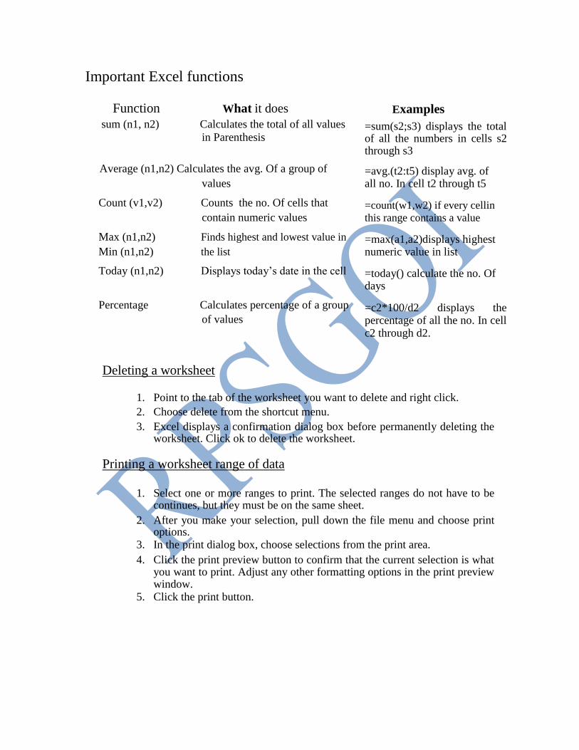
Important Excel functions
Function What it does sum (n1, n2) Calculates the total of all values
in Parenthesis
Average (n1,n2) Calculates the avg. Of a group of values
Count (v1,v2) Counts the no. Of cells that
contain numeric values
Max (n1,n2) Finds highest and lowest value in Min (n1,n2) the list
Today (n1,n2) Displays today’s date in the cell
Percentage Calculates percentage of a group of values
Examples =sum(s2;s3) displays the total of all the numbers in cells s2 through s3 =avg.(t2:t5) display avg. of all no. In cell t2 through t5 =count(w1,w2) if every cellin
this range contains a value =max(a1,a2)displays highest numeric value in list =today() calculate the no. Of days =c2*100/d2 displays the percentage of all the no. In cell c2 through d2.
Deleting a worksheet
1. Point to the tab of the worksheet you want to delete and right click. 2. Choose delete from the shortcut menu. 3. Excel displays a confirmation dialog box before permanently deleting the
worksheet. Click ok to delete the worksheet.
Printing a worksheet range of data
1. Select one or more ranges to print. The selected ranges do not have to be
continues, but they must be on the same sheet.
2. After you make your selection, pull down the file menu and choose print options.
3. In the print dialog box, choose selections from the print area. 4. Click the print preview button to confirm that the current selection is what
you want to print. Adjust any other formatting options in the print preview window.
5. Click the print button.
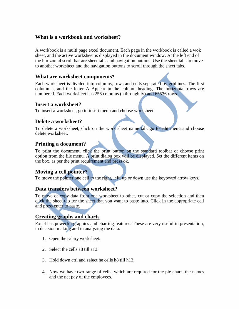
What is a workbook and worksheet?
A workbook is a multi page excel document. Each page in the workbook is called a wok sheet, and the active worksheet is displayed in the document window. At the left end of the horizontal scroll bar are sheet tabs and navigation buttons .Use the sheet tabs to move to another worksheet and the navigation buttons to scroll through the sheet tabs.
What are worksheet components? Each worksheet is divided into columns, rows and cells separated by gridlines. The first column a, and the letter A Appear in the column heading. The horizontal rows are numbered. Each worksheet has 256 columns (a through iv) and 65536 rows.
Insert a worksheet? To insert a worksheet, go to insert menu and choose worksheet
Delete a worksheet? To delete a worksheet, click on the work sheet name tab, go to edit menu and choose delete worksheet.
Printing a document? To print the document, click the print button on the standard toolbar or choose print option from the file menu. A print dialog box will be displayed. Set the different items on the box, as per the print requirement and press ok.
Moving a cell pointer? To move the pointer one cell to the right, left, up or down use the keyboard arrow keys.
Data transfers between worksheet? To move or copy data from one worksheet to other, cut or copy the selection and then click the sheet tab for the sheet that you want to paste into. Click in the appropriate cell and press enter to paste.
Creating graphs and charts Excel has powerful graphics and charting features. These are very useful in presentation, in decision making and in analyzing the data.
1. Open the salary worksheet.
2. Select the cells a8 till a13.
3. Hold down ctrl and select he cells h8 till h13.
4. Now we have two range of cells, which are required for the pie chart- the names and the net pay of the employees.

5. Click on the chart wizard on the formatting toolbar. The chart wizard appears.
6. In the chart wizard, under the standard types tab, choose pie as chart type.
7. In the sub-type section select the second figure-pie with a 3-d visual effect.
8. Click next. The next step of the chart wizard appears.
9. Click the finish button. The chart appears as an object in the salary worksheet.
10. Click the save button on the standard toolbar to save the worksheet and the chart.
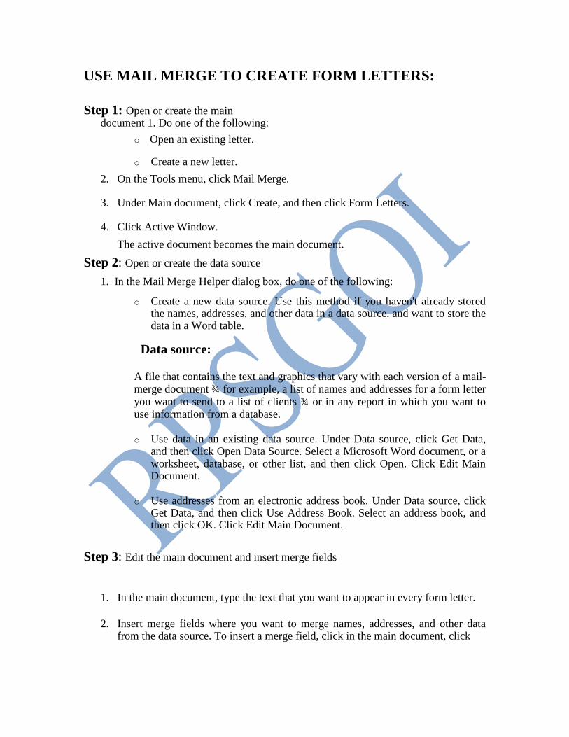
USE MAIL MERGE TO CREATE FORM LETTERS:
Step 1: Open or create the main document 1. Do one of the following:
o Open an existing letter.
o Create a new letter.
2. On the Tools menu, click Mail Merge.
3. Under Main document, click Create, and then click Form Letters.
4. Click Active Window.
The active document becomes the main document. Step 2: Open or create the data source
1. In the Mail Merge Helper dialog box, do one of the following:
o Create a new data source. Use this method if you haven't already stored the names, addresses, and other data in a data source, and want to store the data in a Word table.
Data source:
A file that contains the text and graphics that vary with each version of a mail-merge document ¾ for example, a list of names and addresses for a form letter you want to send to a list of clients ¾ or in any report in which you want to use information from a database.
o Use data in an existing data source. Under Data source, click Get Data,
and then click Open Data Source. Select a Microsoft Word document, or a worksheet, database, or other list, and then click Open. Click Edit Main Document.
o Use addresses from an electronic address book. Under Data source, click
Get Data, and then click Use Address Book. Select an address book, and then click OK. Click Edit Main Document.
Step 3: Edit the main document and insert merge fields
1. In the main document, type the text that you want to appear in every form letter.
2. Insert merge fields where you want to merge names, addresses, and other data
from the data source. To insert a merge field, click in the main document, click

Insert Merge Field on the Mail Merge toolbar, and then click the field name you want.
Merge fields Result after the data is merged
«Title» «First Name» «Last Name» Mr. Paul Martin
«Company» Astro Mountain Bike
«Address1» 987 1st St.
«City», «State» «Postal Code» Kent, WA 55588
3. After you complete the main document and insert all of the merge fields, click Save As on the File menu. Name the document, and then click Save.
Step 4: Merge the data into the main document
1. On the Tools menu, click Mail Merge.
2. If you want to specify the order in which data is merged, or to merge only part of
the data, then you can sort and select data records to merge.
3. If you want to see how the merged data will appear, then you can preview the merged documents.
4. In the Mail Merge Helper dialog box, click Merge under Merge the data with the
document.
5. If you want to check the data source for errors before you merge, click Check Errors. Choose an option, and then click OK.
6. Do one of the following:
* Send the merged letters directly to a printer. In the Merge to box, click Printer, and then click Merge.
* Store the merged letters in a new document, so you can review, edit, and print them later.
* Distribute the merged letters to e-mail addresses or fax numbers. We can summarize the above steps for Creating and Entering Records in a Mail Merge as:
1. Choose Tools> Mail Merge from the menu bar.
2. Choose Create and select a type of main document.

3. Indicate whether you want to use the active window as the main document or to
create a new document. 4. Choose Get Data, and then choose Create Data Source. 5. Review the list of suggested-filed names in the Create Data Source dialog box; delete
field names that you don’t want. 6. Move the insertion point to the position where you want data from the data source to
appear. Click Insert Merge Field and select field names from the insert merge fields at the desired position.
Experiment-3
AIM:- To Study Microsoft power point .
WHAT IS POWER POINT? Power point is a complete presentation graphics package. It has the powerful features like power point wizards, toolbars and power point views to create good slides. It has all the tools required to produce a professional looking presentation, such as text handling, outlining, and drawing graphics, clipart and so on. Speaker supports and aids help you to create truly effective presentations. It has wizard, auto layouts, and a complete set of easy to use tools assuring you to have everything you need to share your knowledge with others.
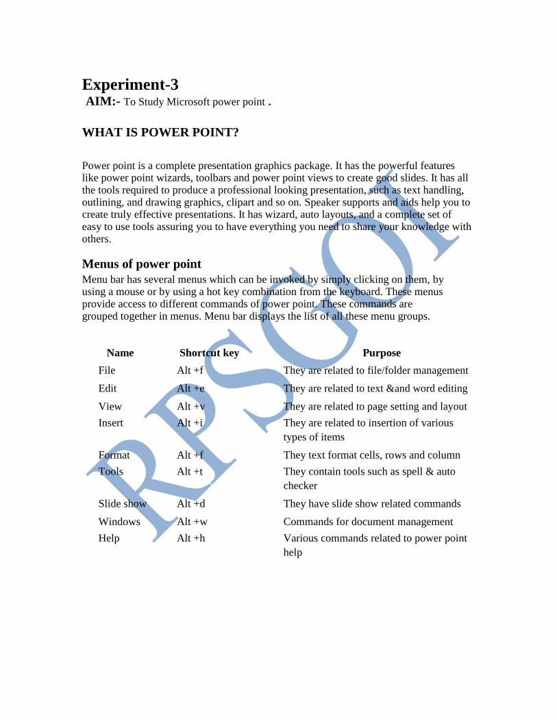
Menus of power point Menu bar has several menus which can be invoked by simply clicking on them, by using a mouse or by using a hot key combination from the keyboard. These menus provide access to different commands of power point. These commands are grouped together in menus. Menu bar displays the list of all these menu groups.
Name Shortcut key Purpose
File Alt +f They are related to file/folder management
Edit Alt +e They are related to text &and word editing
View Alt +v They are related to page setting and layout
Insert Alt +i They are related to insertion of various
types of items
Format Alt +f They text format cells, rows and column
Tools Alt +t They contain tools such as spell & auto
checker
Slide show Alt +d They have slide show related commands
Windows Alt +w Commands for document management
Help Alt +h Various commands related to power point
help
Power point is a good way to communicate ideas simply and effectively. For complex topics that are rich with details, such as a scientific paper or an annual report. Each presentation consists of one more pages or slides, which can contain text, bulleted lists, graphics, charts and other data types.
Insert a new slide
To insert a new slide, you can perform any of the following tasks.
1. Insert a slide, go to insert menu and choose slide. 2. Choose a new slide button from standard tool bar.
3. From the power point startup screen, choose blank presentation. 4. If power point is already open, pull down the file menu. Choose new, select blank
presentation from the general tab, and click ok. 5. Click the new button on the standard toolbar.
Delete a new slide
To delete a slide, make that slides current slide and choose duplicate slide from the edit menu. Slide will be deleted immediately.
Duplicate a slide
To duplicate a slide make that slide current slide and choose duplicate slide from the edit menu.
Creating master slide
If you want to have certain common items on all the pages without adding them individually to the slides one by one, create a master slide. The items contained in master slide will automatically become the items for all the slides.
What are presentation graphics?
Presentation graphics is an application software available for designing charts. You can perform any of the following tasks.
1. Design characters.
2. Arrange the matter in readable form. 3. Add pictures in the charts.
4. Change the appearance of the alphabets on the charts.
5. Print these charts.
To display slide setup
Ina new presentation, the slides by default have a width of 10inches, height of 7.5 inches and landscape orientation. These settings can be changed using the page setup commands. The procedure for changing the slide setup is follows: 1. Click on the main menu option. 2. Click on the page setup command, the page setup dialogue box with the default
settings appear on the screen. 3. Click on the slides sized for dropdown arrow.
4. Click on letter paper (8.5*11 in).
5. Click on the portrait radio button. 6. Click on the ok button to change slide settings for every slide in your
presentation. The slides will now be 10inches in height, have a width of 7.5inches and the orientation will be portrait.
Saving a presentation To save a presentation on disk, click the save button on the standard or choose save option or save as option from the file menu. Option save is to save the file with current name and save as the command to save file with some other name.
To display a slide show
A presentation can be displayed on the screen by running a slide show. The slides can be advanced manually or automatically. The procedure for running the slide show is:
1. Click on the slide button. At the bottom of the slide to begin the slide show. 2. Select slide show from the view menu to display a dialog box.
3. One slide is displayed at a time each slide fills the entire screen. 4. Click on the left mouse button or press enter or press page down to move one
slide forward. 5. When we reach the last slide in the presentation, power point brings us back to
the slide view, or any other view that we are in. 6. Click on file menu option
7. Click on close command to close the presentation. 8. Click on exit command to exit from the power point.
Printing a presentation
1. Choose file menu print to open the print dialog box. 2. In the print range area, choose the slides to be printed. 3. In the print what drop – down list, select whether to print slides, handouts,
notes pages, or an outline. 4. Set other print options.
5. Click ok begin printing.
Adding a clip art to a slide 1. Choose insert<picture >clipart or double- click a clip art placeholder to open
the insert clip art dialog box. 2. Select the picture you want to insert and click insert menu.
Experiment-4
Aim:-To Study Microsoft Access. Database A Database is a collection of related items grouped together under a single heading. E.g. student details, Bank Account, Employee Details etc. Database can be said to be a collection of files containing records of similar nature. Each record contains all the data relating to one subject in the file.
Using Microsoft access we can manage all your information from a single database file. Within the file, divide the data into separate storage containers called tables; view, add, and update table data by using online forms; find and retrieve just the data we want by using queries and analyze or print data in a specific layout by using reports. Allow users to view or an intranet by creating data access pages.
• To store data, create one table for each type of information that you track. To bring the data from multiple tables together in a query, form, report, or data access page, define relationships between the tables.
• To find and retrieve just the data that meets conditions that WE specify,
including data from multiple tables, create a query. A query can also update or delete multiple records at the same time, and perform predefined or custom calculations on the data.
• To easily view, enter, and change data directly in a table, create a form. When we open a form, Microsoft Access retrieves the data from one or more tables, and displays it on the screen with the layout choosen in the Form Wizard, or a layout that is created from scratch.
• To analyze data or present it a certain way in print, create a report. For example, you might print one report that groups data and calculates totals, and another report with different data formatted for printing mailing labels.
• To work with all the objects in a Microsoft Access database a Database window is used.
Tables A table is an effective way to store your data. Properly organized and well-designed tables increase productivity. Tables are the primary objects used to store data. Tables are often built to store information of particular object. In today's scenario it is becoming more common to type data directly into the database table.
Creating a Table You can create a table using 'Design View', or 'Table Wizard' to create an initial table, which you can modify later if needed. The 'Table Wizard' provides options for selecting fields, field property, and a table title. You have three option to create table: a) Create table in Design View.
b) Create table by using wizard. c) Create table by entering data.
Using Design View
1. Select 'Tables' tab From the Database view, click 'New' and then choose 'Design View' from the 'New Table' dialog box, and click OK. 2. Enter a field name in the first row of the Field Name Column.
3. Press Enter or Tab to move to the Data Type Field.
4. Enter a data type for this field. Access will scroll using the first letter of the data type, or you can also use the drop down list provided to you. 5. Alter the Field Properties section of the table design grid as needed.
6. Add a comment in the description column for your better understanding.
Using Table Wizard
1. Open the 'New Table' Dialog box by using one of the followings:
Select the 'Tables' option from the Insert menu. Select the 'Tables' tab and then click on 'New' button in the Database window. Select the 'New' Object toolbar button and choose the Table option. 2. Select table type from the 'New Table' Dialog box.
3. Select table and field from the list of sample tables and sample fields.
4. Give title of the table and create relationship if exist.
Datasheet View to Make a Table
1. Launch MS Access and start a new blank database. Access now launches a blank table for use. 2. Enter data for the first field in the first row.
3. Right click on the first column header (labeled Field 1) and choose Rename from the shortcut menu. This allows you to change the column header, change it to Employee ID for this field.
4. Enter come name data for each of the next three fields, editing the field names to Last Name, First Name, and Middle Name respectively. 5. Move to the next column, Enter yes.
6. Move to the next column to enter date.
7. Click on the Save icon in the toolbar.
8. Click the view button to switch to Design View.
Table and Field Properties
After you have entered the field names, data types and an optional description, you may want to further refine the data design and have more control over the way data is stored, formatted and validated. You can specify all these characteristics of a field in the Field Properties Pane in the Design view. The properties of a field are the characteristics that define the field. Two properties are required for every field: field name and data type. Many other properties, such as field size, format, caption, and default value, are defined in the Field Properties section of the table's Design View.
As you specify more property entries, you are generally restricting the amount or type of data that can be entered in the field, which increases data entry accuracy. The available field properties vary depending on the data type of the selected field.
The Caption property, however, allows you to override a technical or sample field name (for example, Project Description) with an easy-to-read caption entry (that is, Project Description) when the field name is displayed on datasheets, forms, and reports.
Forms Properly organized and well-designed forms increase productivity. Forms are the primary objects used to enter and edit data. Forms are often built to match a source document (for example, an employment application or a medical history form) to facilitate fast and accurate data entry. Now, however, it is becoming more common to type data directly into the database rather than first recording it on paper. When data is viewed in many ways, forms provide a great degree of flexibility for viewing and entering data. Though a datasheet also allow you to view many records at a time, the number of fields that can be seen is limited. Forms, on other hand can help you rearrange fields and view many more on a single screen. Form design considerations, such as clearly labeled fields and appropriate formatting, are important. Other considerations include how the user tabs from field to field, and what type of control is used to display the data.
Types of Forms 1. Columnar Forms.
2. Tabular Forms.
3. Main/Subforms.
Columnar Forms The fields are arranged as columns and resemble a manual data entry form.
Tabular Forms The fields are arranged as columns and the records are entered in rows. Thus, it resembles a datasheet.
Main/Sub form This type of form is normally used to depict one to many relationships. The main form displays the main record and sub form displays the records from the related table in Datasheet view.
Creating a Form with a wizard
In the database window, click Forms under Objects. 1. Click the new button on the database on the Database window toolbar. 2. In the New Form dialog box, click the wizard that you want to use. A description
of the wizard appears in the left side of the dialog box. 3. Click the name of the table or other record source that includes the data you want
to base your form on. 4. Click OK. 5. If you clicked Form Wizard, Chart Wizard, or Pivot Table Wizard in step 3,
follow the directions in the wizard dialog boxes. If you clicked Auto Form: Columnar, AutoForm : Tabular, or AutoForm : Datasheet, Microsoft Access automatically creates your form.
Reports
A report is an effective way to present your data in a printed format. A report is a flexible way of viewing and printing summary information. It enables you to display information of the required level of detail. The information can be viewed or printed in any format. Subtotals, statistical evaluations, pictures and graphs can be inserted in a report. Because you have control over the size and appearance of everything on a report, you can display the information the way you want to see it.
Create a Report with a wizard
1. Launch Access and open the database in which you want to build a report.
2. Locate the New button on the Database view toolbar. Click that button to start new report.
3. Choose Report Wizard from the list box. Pull down the combo box at the bottom of the dialog box to choose the query or any other object for the report basis.
4. Click OK to start the actual wizard process. Specify the field what you want to be part of your report. 5. The next dialog box enables you to specify what fields to group on, if any.
6. You can specify the sort in the next dialog box. In the next dialog box you can choose the layout of the report.
7. Give the name to the report which describes the outline of the report and then click
Finish button to accomplish your task and to see the preview of your report. A report
preview is a screen view of how your report will look on the web or from a printer.
Open a Report
1. In the database window, click Reports under Objects.
2. Click the Report you want to open.
3. On the Database window toolbar, click the Design button to open the report in
Design view, or click the Preview button to open the report in Print Preview.
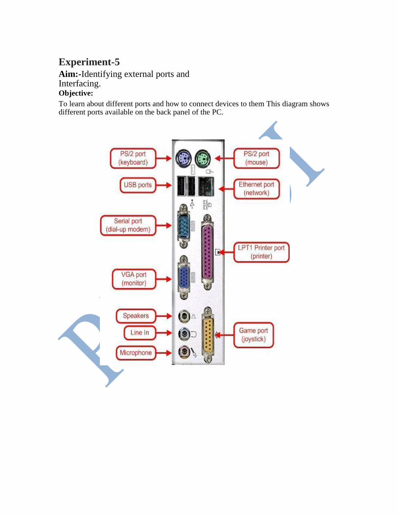
Experiment-5 Aim:-Identifying external ports and Interfacing. Objective: To learn about different ports and how to connect devices to them This diagram shows different ports available on the back panel of the PC.
Parallel port (LPT parallel port): As shown in the diagram parallel port with 25-pins can be used to connect a parallel port
printer. Previously dot matrix, ink jet, bubble jet printers etc were connected to parallel
port. Nowadays-parallel port is used to connect Dot-Matrix printers.
Serial port: As shown in the diagram serial ports with 9-pins protruding outwards can be used to connect modem but it can also be used for connecting mouse, provided serial port mouse is available.
VGA Port: VGA port which has 15-pins is used to connect a monitor.
PS/2 Port: Two 6-pin PS/2 ports are there, one is violet to which keyboard is connected and other is Light green to which mouse is connected
USB Port: Connecting a USB device to a computer is simple — you find the USB connector on the back of your machine and plug the USB connector into it. USB pots are used to connect to Injket printers, Web Cams, Scanners etc.
Ethernet Port: Ethernet port is used to connect a computer on network through RJ-45 connector . Game Port: Game Port is used to connect joystick, which is usually used in video games
Three more ports are available for multimedia connections. Green port is used connect speakers, blue port is used to connect headphones and light Orange is used to connect microphone.
Experiment-6
AIM:-To make comparative study of motherboards
The motherboard is the main circuit board inside the PC which holds the Error! Hyperlink reference not valid., memory and expansion slots and connects directly or indirectly to every part of the PC. It's made up of a chipset (known as the "glue logic"), some code in ROM and the various interconnections or buses. PC designs today use many different buses to link their various components. Wide, high-speed buses are difficult and expensive to produce: the signals travel at such a rate that even distances of just a few centimeters cause timing problems, while the metal tracks on the circuit board act as miniature radio antennae, transmitting electromagnetic noise that introduces interference with signals elsewhere in the system. For these reasons, PC design engineers try to keep the fastest buses confined to the smallest area of the motherboard and use slower, more robust buses, for other parts.
All motherboards include a small block of Read Only Memory (ROM) which is separate from the main system memory used for loading and running software. The ROM contains the PC's Basic Input / Output System (BIOS). This offers two advantages: 1. The code and data in the ROM BIOS need not be reloaded each time the computer is started 2. They cannot be corrupted by wayward applications that write into the wrong part of memory. A Flash up gradeable BIOS may be updated via a floppy diskette to ensure future compatibility with new chips, add-on cards etc.
Parts of motherboard are:: 1. Chipsets
2. Processor slot
3. I/O processor slot
4. IDE slots
5. COM ports
6. Power slots
7. PCI slots
8. RAM slots
9. Power sockets
10. COM slots
11. DIMM(Dual In Memory Module)
12. Co-processor sockets for CPU, PCB etc.
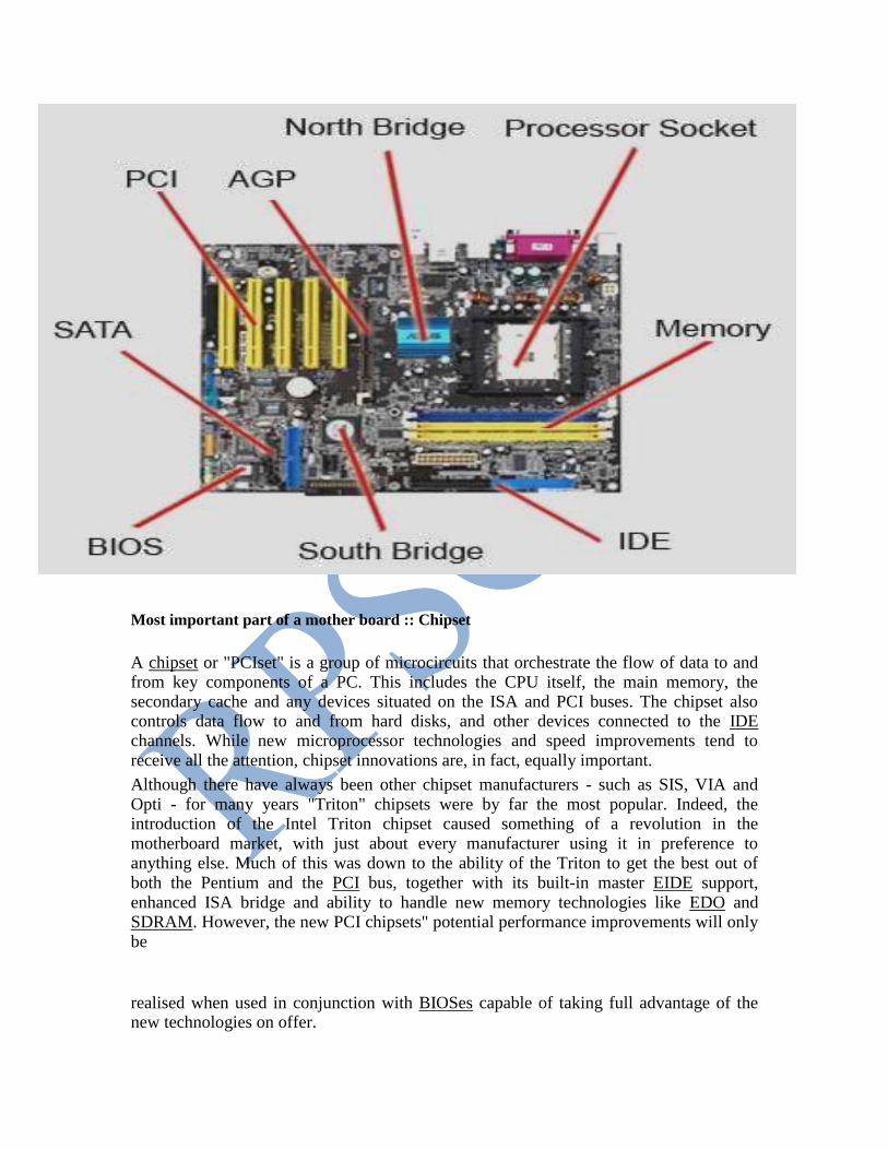
Most important part of a mother board :: Chipset
A chipset or "PCIset" is a group of microcircuits that orchestrate the flow of data to and from key components of a PC. This includes the CPU itself, the main memory, the secondary cache and any devices situated on the ISA and PCI buses. The chipset also controls data flow to and from hard disks, and other devices connected to the IDE channels. While new microprocessor technologies and speed improvements tend to receive all the attention, chipset innovations are, in fact, equally important. Although there have always been other chipset manufacturers - such as SIS, VIA and Opti - for many years "Triton" chipsets were by far the most popular. Indeed, the introduction of the Intel Triton chipset caused something of a revolution in the motherboard market, with just about every manufacturer using it in preference to anything else. Much of this was down to the ability of the Triton to get the best out of both the Pentium and the PCI bus, together with its built-in master EIDE support, enhanced ISA bridge and ability to handle new memory technologies like EDO and SDRAM. However, the new PCI chipsets" potential performance improvements will only be
realised when used in conjunction with BIOSes capable of taking full advantage of the new technologies on offer.

During the late 1990s things became far more competitive, with Acer Laboratories (ALI),
SIS and VIA Technologies all developing chipsets designed to operate with Intel, AMD and Cyrix processors. 1998 was a particularly important year in chipset development,
with what had become an unacceptable bottleneck - the PC's 66MHz system bus - to finally being overcome. Interestingly, it was not Intel but rival chipmakers that made the
first move, pushing Socket 7 chipsets to 100MHz. Intel responded with its 440BX, one of many chipsets to use the ubiquitous Northbridge/Southbridge architecture. It was not long
before Intel's hold on the chipset market loosened further still, and again, the company
had no-one but itself to blame. In 1999, its single-minded commitment to Direct Rambus DRAM (DRDRAM) left it in the embarrassing position of not having a chipset that
supported the 133MHz system bus speed its latest range of processors were capable of. This was another situation it's rivals were able to exploit, and in so doing gain market
share.
Form factor Early PCs used the AT form factor and 12in wide motherboards. The sheer size of an AT motherboard caused problems for upgrading PCs and did not allow use of the
increasingly popular slimline desktop cases. These problems were largely addressed by
the smaller version of the full AT form factor, the Baby AT, introduced in 1989. Whilst this remains a common form factor, there have been several improvements since. All
designs are open standards and as such don't require certification. A consequence is that there can be some quite wide variation in design detail between different manufacturers'
motherboards.
ATX – type of mother board Designed and released in 1995 Intel ATX is a new motherboard form factor with a physical design like the traditional board (30.5 cm X 19 cm) shifted 90 degrees for a better placing of the units. The I/O connectors COM1, COM2 and LPT, keyboard, mouse and USB are mounted directly on the motherboard. The ATX board requires specifically designed chassis with an I/O access opening measuring 1¾ by 6¼ inch. The ATX motherboard includes advanced control facilities, where the BIOS program continually checks the CPU temperature and voltages, the cooling fans RPM, etc. If over heating occurs, the PC will shut down automatically. The PC can also be turned on by for example modem signals, since the power supply is controlled by the main board. The on/off button will turn the PC "down" without turning it completely off. The computer will also not be able to be turned off while the computer boots up, if however the computer freezes as it is turning on to turn the computer off you must press and hold the power button for 5 seconds and it will turn off.
Experiment-07
AIM:- STUDY OF VARIOUS CARDS USED IN THE SYSTEM In a computer a mother board , we use many types of cards . These are named as following ::---- 1. PCI Card ( Peripheral Communication Interface ) 2. ISA Card ( Industry Standard Architecture ) 3. AGP Card ( Accelerated Graphic Port ) 4. AMR Card ( Audio Modem Riser ) 5. VGA Card (Video Graphics Array ) 6. LAN Card ( Local Area Network ) 7. SOUND Card
8. MODEM (Modulator Demodulator )
PCI CARD :: We can adjust these cards in PCI slots in the mother board . PCI was originally developed by Intel as an expansion to the ISA bus.
ISACARD:: We can adjust this card in the ISA slots on the mother board. Short for Industry Standard Architecture, ISA is a standard of computer bus. Below is an illustration of what a ISA expansion card may look like.
AGP CARD ::

This card can be used for Advanced Graphical purpose . The resolution
capacity of this card is much better than any other card . This card can be used only for the graphics . Short for Accelerated Graphics Port, AGP is an
advanced port designed for Video cards and 3D accelerators. Designed by Intel, August of 1997 AGP introduces a dedicated point-to-point channel so
that the graphics controller can directly access the system memory. Below is an illustration of what the AGP slot may look like on your your
motherboard.
The AGP channel is 32-bits wide and runs at 66 MHz. This translates into a total bandwidth of 266 MBps, as opposed to the PCI bandwidth of up to 133 MBps. AGP also supports two optional faster modes, with throughputs of 533 MBps and 1.07 GBps. and also allows 3-D textures to be stored in main memory rather than video memory.
Each computer with AGP support will either have one AGP slot or onboard AGP video. If the user wishes to have multiple video cards in the computer they would have one AGP video card as well as one or more PCI video cards.
The AGP aperture size is an available option configurable commonly through the computer BIOS that is commonly set to a default of 64MB. AGP aperture size defines how much system memory the AGP controller is
allowed to use for texture maps. While it may be possible to increase the overall performance or prevent problems with some video cards we
recommend you leave the AGP aperture size at 64MB unless instructed otherwise by your video card manufacture.
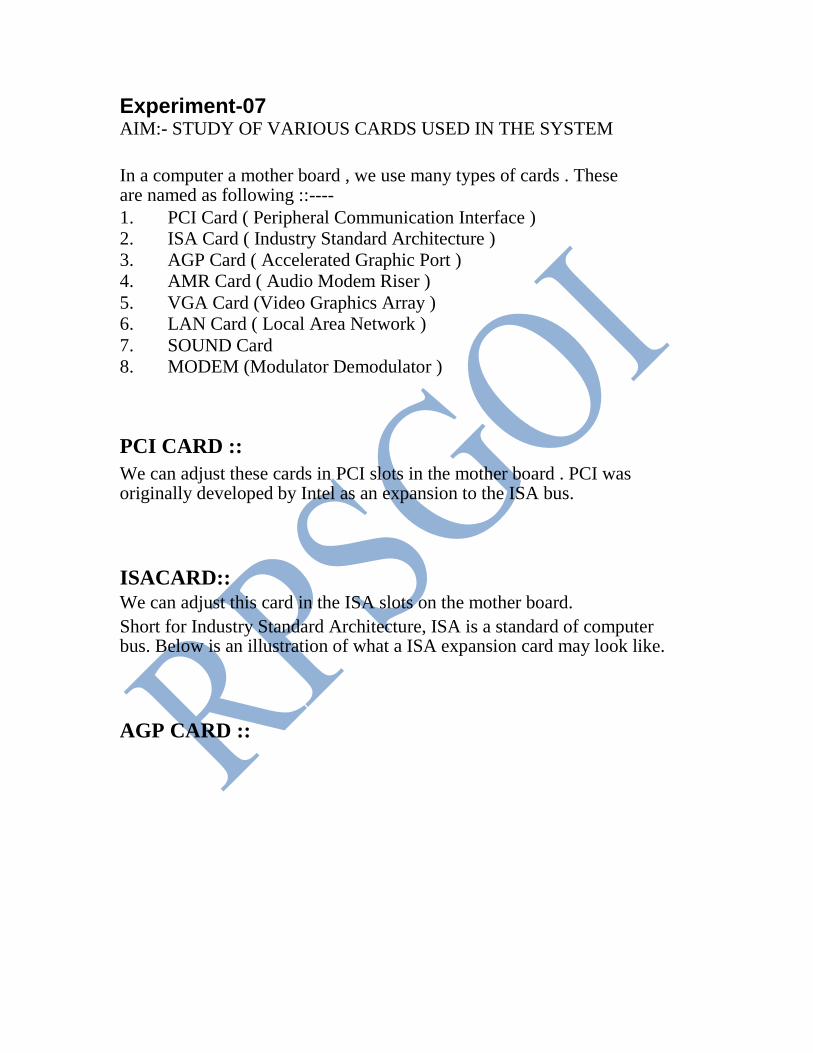
LAN CARD
Built to run with the fastest network applications, the Ether Fast®
10/100 LAN CARD is a high performance network adapter for desktop computers
with 32 bit PCI Expansion slots. The Ether Fast ®
10/100 LAN CARD is ready to run with both 10 BaseT and 100 BaseTX networks right out of the box-the card’s 10/100 combo RJ – 45 port automatically detects your
network’s maximum speed and adjust itself accordingly. The Ether Fast ®
10/100 LAN CARD from Linksys also features Wake – On – LAN (WOL) event management. If your PCI motherboard has built -in WOL support, you’ll be able to utilize this unique management feature. You can remotely turn on any computer with WOL network card. The ultimate in 10/100 networking is yours! If you don’t have WOL support on your motherboard
or you have no need for it, don’t worry ---- your EtherFast®
10/100 LAN CARD will operate normally anyway. If your mission critical applications
require blinding network speed, the EtherFast ®
10/100 LAN CARD is the best value for your networking dollar.
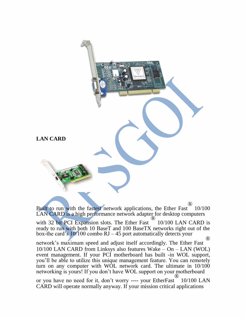
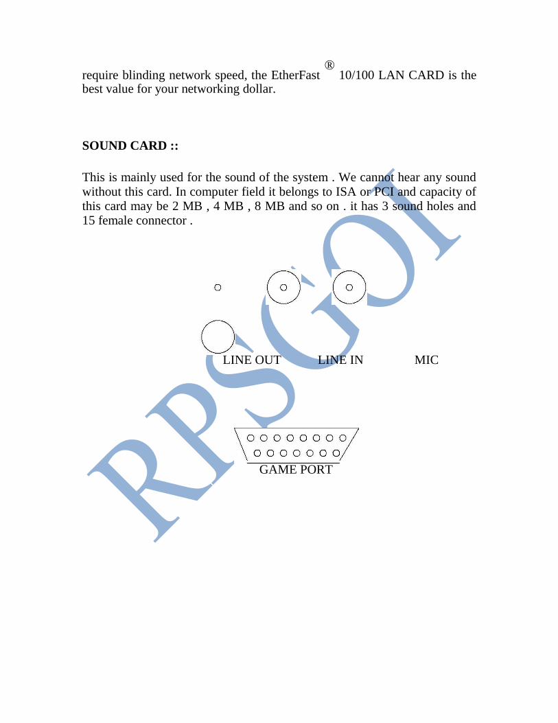
SOUND CARD ::
This is mainly used for the sound of the system . We cannot hear any sound without this card. In computer field it belongs to ISA or PCI and capacity of this card may be 2 MB , 4 MB , 8 MB and so on . it has 3 sound holes and 15 female connector .
LINE OUT LINE IN MIC
GAME PORT
SOUND CARD
MODEM:: Modems are of two types :: 1. Internal modem
2. External modem
MODEM comes in card share . It adjusts inside the cabinet . It is
used for internet facility. Its speed can be measured in KB/PS .
Now-a-days the internal modem’s speed is 56 KB/s . It has 2 RJ –
11 socket . One is used for LINE and other is used for PHONE .

Experiment-08
Aim:-To remove, study and replace floppy disk drive.
FLOPPY DISKS ::
They are the main storage device for a personal computer . To use the floppy disk in a computer , a Floppy Disk Drive ( FDD ) and an Interface to connect the computer with the disk drive is required . These storage devices are also called as “EXTERNAL STORAGE DEVICES “ . These are available in 3.5 inch & 5.25 inch in size . 5.25 inch drive are very common with PC & XT class machines . But they are slowly getting replaced with 3.5 inch drive . Now-a-days most common drives are 1.44 MB – 3.5 inch disk drive . 200 MB floppy disk drive is also used now-a-days in the big industries.
Parts of a Floppy Disk Drive ::
1. Read / Write Head 2. Head Actuator / Stepper Motor 3. Spindle Motor 4. Circuit Board 5. Cable Connector 6. Face Plate
3.5”Floppy diskette Below we have represented a picture of the now commonly used 3.5" floppy diskettes. The below representation is what the back of a floppy diskette looks like. As you can see there are four main visible parts:
First the top left of the back of the floppy there is a small tab. This tab enables the floppy disk to be switched from write protected and un-write protected. Move the tab to the top position creating a hole makes the disk write protected. This means that nothing can be written, erased or deleted from the diskette. Moving the tab to the bottom position allows the disk to be un-write protected. Which means the diskette can be written too, erased and or have information deleted from the diskette. Some diskettes which are generally cheaper diskettes will be missing this tab. To write information to the diskette you will have to place a piece of scotch tab over the whole.
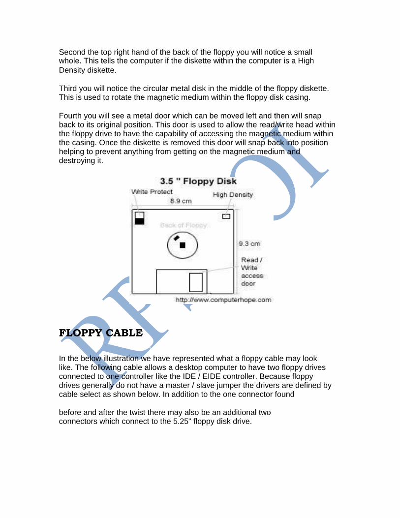
Second the top right hand of the back of the floppy you will notice a small whole. This tells the computer if the diskette within the computer is a High Density diskette.
Third you will notice the circular metal disk in the middle of the floppy diskette. This is used to rotate the magnetic medium within the floppy disk casing.
Fourth you will see a metal door which can be moved left and then will snap back to its original position. This door is used to allow the read/write head within the floppy drive to have the capability of accessing the magnetic medium within the casing. Once the diskette is removed this door will snap back into position helping to prevent anything from getting on the magnetic medium and destroying it.
FLOPPY CABLE In the below illustration we have represented what a floppy cable may look like. The following cable allows a desktop computer to have two floppy drives connected to one controller like the IDE / EIDE controller. Because floppy drives generally do not have a master / slave jumper the drivers are defined by cable select as shown below. In addition to the one connector found
before and after the twist there may also be an additional two connectors which connect to the 5.25" floppy disk drive.
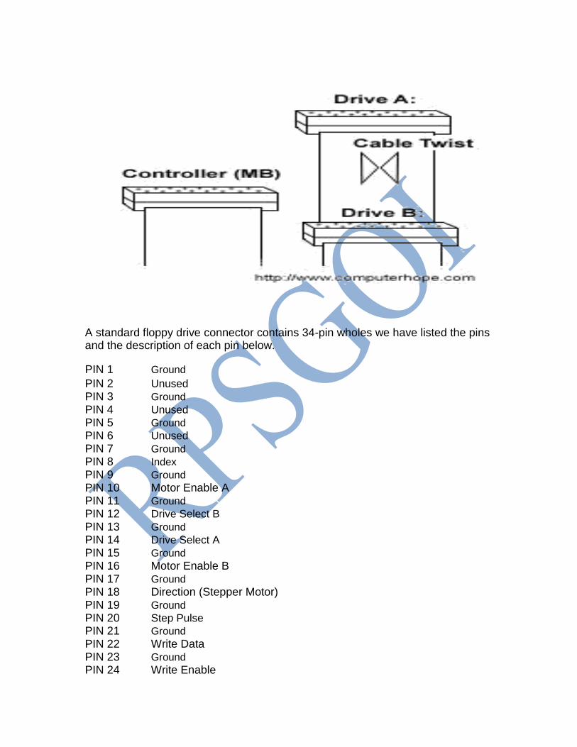
A standard floppy drive connector contains 34-pin wholes we have listed the pins and the description of each pin below. PIN 1 Ground PIN 2 Unused
PIN 3 Ground
PIN 4 Unused
PIN 5 Ground
PIN 6 Unused
PIN 7 Ground
PIN 8 Index
PIN 9 Ground
PIN 10 Motor Enable A
PIN 11 Ground
PIN 12 Drive Select B
PIN 13 Ground
PIN 14 Drive Select A PIN 15 Ground
PIN 16 Motor Enable B
PIN 17 Ground
PIN 18 Direction (Stepper Motor) PIN 19 Ground
PIN 20 Step Pulse
PIN 21 Ground
PIN 22 Write Data
PIN 23 Ground PIN 24 Write Enable
PIN 25 Ground PIN 26 Track 0
PIN 27 Ground
PIN 28 Write Protect
PIN 29 Ground
PIN 30 Read Data
PIN 31 Ground
PIN 32 Select Head 1
PIN 33 Ground
PIN 34 Ground
FLOPPY DRIVE ABCs Originally created in 1967 by IBM. The floppy reference is derived from the floppy media that is encased within the protective casing. This media is a magnetic medium and is written to much like the method used by hard disk drives. Floppy drives have been found in computers for several years and are commonly still being used today. The next generation of floppy drives will more then likely be the LS-120 diskette drives which are already being included in many computers now.
Experiment-09
AIM:-STUDY, REMOVAL AND REPLACE OF HARD DISK. A hard disk is made up of a collection of disk known as PLATTERS. Platters is coated with the material that allows data to be recorded magnetically . The disk rotate at the very high speed. The typical speed is 3600 RPM. Hard disk of capacities are 40,80,120 GB are available currently. They are installed inside the computer and excess data more quickly than a floppy disk can.
Installing an IDE (Intelligent Device Electronics)
It can be installed in following ways : 1. Connect the IDE cable to the drive and drive controller. 2. Make sure that the IDE cable is properly connected which can be
checked by checking that the red strip is aligned with PIN 1 on each connector.
HARD DISK DRIVE ORGANISATION::
A Hard disk consists of electronic circuits and electromechanical sub systems. The electromechanical sub systems in a hard disk are: 1. READ / WRITE HEAD. 2. DISK PLOTTER. 3. SPINDLE. 4. Positioning of mechanism. 5. A circulation system. 6. Air filter.
Hard Disk Interfaces and Configuration The interface that the hard disk uses to connect to the rest of the PC is in some ways as important as the characteristics of the hard disk itself. The interface is the communication channel over which all the data flows that is read from or written to the hard disk. The interface can be a major limiting factor in system performance. The choice of interface also has an essential impact on system configuration, compatibility, up gradability and other factors.
Over time, several different standards have evolved to control how hard disks are connected to the other major system components used in the PC. These have tended to build upon one another, and often use confusing and overlapping terminology. The result has been a great deal of confusion surrounding the entire
subject. Each time a new variant or enhancement of an interface is introduced, the interface becomes just a
bit more confusing, particularly for those trying to use older hardware, or to mix newer and older devices.
Hard Disk Drives
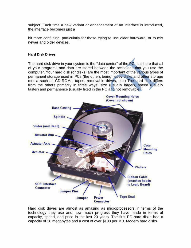
The hard disk drive in your system is the "data center" of the PC. It is here that all of your programs and data are stored between the occasions that you use the computer. Your hard disk (or disks) are the most important of the various types of permanent storage used in PCs (the others being floppy disks and other storage media such as CD-ROMs, tapes, removable drives, etc.) The hard disk differs from the others primarily in three ways: size (usually larger), speed (usually faster) and permanence (usually fixed in the PC and not removable).]
Hard disk drives are almost as amazing as microprocessors in terms of the technology they use and how much progress they have made in terms of capacity, speed, and price in the last 20 years. The first PC hard disks had a capacity of 10 megabytes and a cost of over $100 per MB. Modern hard disks

have capacities approaching 100 gigabytes and a cost of less than 1 cent per MB! This represents an improvement of
1,000,000% in just under 20 years, or around 67% cumulative improvement per year. At the same time, the speed of the hard disk and its interfaces have increased dramatically as well. Your hard disk plays a significant role in the following important aspects of your computer system:
Performance:
The hard disk plays a very important role in overall system performance, probably more than most people recognize (though that is changing now as hard drives get more of the attention they deserve). The speed at which the PC boots up and programs load is directly related to hard disk speed. The hard disk's performance is also critical when multitasking is being used or when processing large amounts of data such as graphics work, editing sound and video, or working with databases. Storage Capacity: This is kind of obvious, but a bigger hard disk lets you store more programs and data. Software Support: Newer software needs more space and faster hard disks to load it efficiently. It's easy to remember when 1 GB was a lot of disk space; heck, it's even easy to remember when 100 MB was a lot of disk space! Now a PC with even 1 GB is considered by many to be "crippled", since it can barely hold modern (inflated) operating system files and a complement of standard business software. Reliability: One way to assess the importance of an item of hardware is to consider how much grief is caused if it fails. By this standard, the hard disk is the most important component by a long shot. As I often say, hardware can be replaced, but data cannot. A good quality hard disk, combined with smart maintenance and backup habits, can help ensure that the nightmare of data loss doesn't become part of your life.
Hard Disk Performance, Quality and Reliability When considering the actual "real world" daily use of hard disks, and contemplating a hard disk purchase, PC users often ask three key questions: 1. Is this hard disk fast? 2. Is this hard disk well manufactured? 3. Is this hard disk going to last?
Hard disk performance is important because hard disks are one of the slowest
internal PC components, and therefore often limit the performance of the system
as a whole. Quality and reliability are critical with hard disks, because they are where your data resides! No other PC component can lead so readily to disaster if it fails. And hard disk quality and reliability remain mysteries to many users, who buy whatever seems fast and cheap, and simply hope for the best. Subsections contained here are : The first takes a very detailed look at hard disk performance, discussing different ways that performance can be assessed, common performance specifications, ways of measuring performance, and also describing the various factors inside and outside the hard disk that affect its speed. The second looks at hard disk quality and reliability issues in detail, including a look at warranty issues and features being put into hard disks to improve their reliability. The third major subsection is devoted to the discussion of Redundant Arrays of Inexpensive Disks, or RAID. The use of disk arrays is increasing dramatically as the PC world seeks to improve performance, expand storage capacity, and improve the reliability of the storage subsystem.
Hard Disk BIOS and Capacity Factors
The operation of your hard disk drives is controlled by the interface from the system to the hard disk itself. This interface is the conduit for addressing instructions and commands, sent to the hard disk to select what data is requested, and then a conduit for the data itself, flowing to and from the system. The system BIOS plays a role in the operation of the hard disk, as it provides the standard software routines that allow applications and operating systems such as DOS to access the hard disk. It is also the cause of many configuration and capacity limitation problems that many users have when setting up their hard disks, especially newer ones on older systems.
Hard Disk Logical Structures and File Systems
The hard disk is, of course, a medium for storing information. Hard disks grow in size every year, and as they get larger, using them in an efficient way becomes more difficult. The file system is the general name given to the logical structures and software routines used to control access to the storage on a hard disk system. Operating systems use different ways of organizing and controlling access to data on the hard disk, and this choice is basically independent of the specific hardware being used--the same hard disk can be arranged in many different ways, and even multiple ways in different areas of the same disk. The information in this section in fact straddles the fine line between hardware and software, a line which gets more and more blurry every year.
The nature of the logical structures on the hard disk has an important influence on the performance, reliability, expandability and compatibility of your storage

subsystem. This section takes a look at the logical structures on the hard disk and how they are set up and used for a typical PC installation. I begin with a discussion of different PC operating systems, and an overview of different file system types. I then go into significant detail describing the major structures and key operating details of the most common PC file system, FAT (FAT12/FAT16/VFAT/FAT32). I talk about utilities used for partitioning and formatting hard disks, and also talk a bit about disk compression (even though it is no longer nearly as important as it once was.) I place special emphasis on how to organize the disk for maximum performance--while not getting bogged down in the minutiae of optimization where it will buy you little. Most of the focus in this section is on the FAT family of file systems, because these are by far the most commonly used, and also the ones with which I am most familiar. I do mention alternative file systems, but do not go into extensive detail on them, with one exception. Recognizing the growing role of Windows NT and Windows 2000 systems, a separate, comprehensive section has been added that describes the NTFS family of file systems. If you are mostly interested in reading about NTFS, you may want to skip some of the earlier subsections that describe FAT, and skip directly to the NTFS material. Bear in mind, however, that some of the NTFS discussions build upon the descriptions of FAT, since in some ways the file systems are related. So I recommend reading the section in order, if possible.
Experiment-10
Aim:- STUDY, REMOVE AND REPLACE CD ROM DRIVE . CD ROM’s are used to distribute a wide variety of information to books, to games, to images and store a large of information. They can also be carried easily as they are small in size.
TO READ A CD ROM – A device called CD ROM is needed, any information or data on CD. Data can be erased or written onto it with help of a special device called the CD repeater or writer.
CD ROM’s are available in two types:- 1. CD ROM 2. CD R/W
FRONT VIEWS 1. Head phone jack. 2. Head phone volume control. 3. Disk drawers. 4. Busy indicaters. 5. Emergency eject hole. 6. Play /stop / eject button.
BACK VIEWS 1. Digital audio output connector. 2. Master slave jumper slots. 3. Interface connector. 4. Power in connector. 5. Disk diameter.
SPEED
CAPCITY DATA TRANSFER RATE RPM
1X 150 KB/S 300-500
2X 300 KB/S 400-1060
4X 600 KB/S 500-2120
. . .
. . .
. . .
. . .
52X 7800KB/S 10400-27560
INSTALLING THE IDE:-
1. Insert the CD ROM into a free 5.25 inch drive bay. 2. Screw the CD ROM driver. 3. Connect the 4-pin power cable and 40-pins IDE interface cable to the back of
the CD ROM drive. The red edge of the IDE cable corresponding to pin 1of the IDE Interface on the CD ROM drive.
4. Adjust the master slave jumper on the back of the CD ROM drive. 5. Connect the CD ROM drive to the IDE ports of your mother board.


![OF The SAMBO Federation of India [SFI] Constitution of the SFI 2014.pdf · THE SAMBO FEDERATION OF INDIA 11 Hatta Bazar, Mohindergarh , Haryana 123029, INDIA CHAPTER A : MEMORANDUM](https://img.pdfslide.us/doc/110x75/5ac262fb7f8b9a433f8e01ab/of-the-sambo-federation-of-india-sfi-constitution-of-the-sfi-2014pdfthe-sambo.jpg)