Embed Size (px)
Citation preview
Roy Hubbard
Agenda
At the end of this session, you will understand:
The three basic piping systems
Low DeltaT Syndrome – causes, effects, and solutions
Design & Control Considerations (VPF)
2
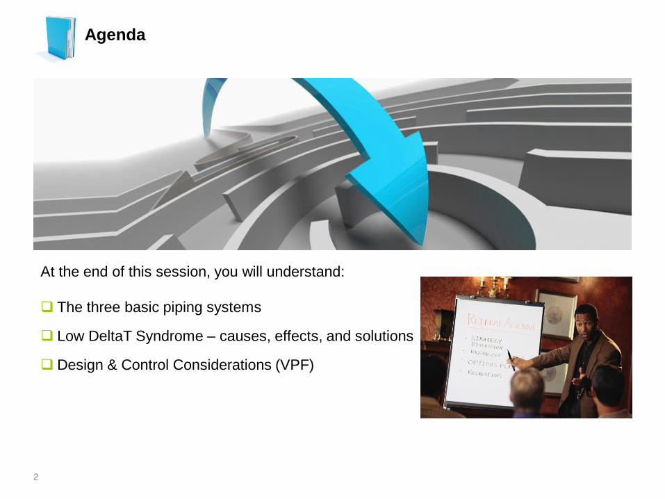
Chilled Water Piping System Types (typical)
3
Configuration
Load
Valves
Installed Cost
Pumping Cost
Constant Primary Flow 3-way Lowest Highest
Primary / Secondary 2-way Highest Medium
Variable Primary Flow 2-way Medium Lowest
Secondary Pumps
= Flow X DeltaT Load
Waterside Load Equation
4
Secondary Pumps
Constant Primary Flow (CPF)
5
Secondary Pumps
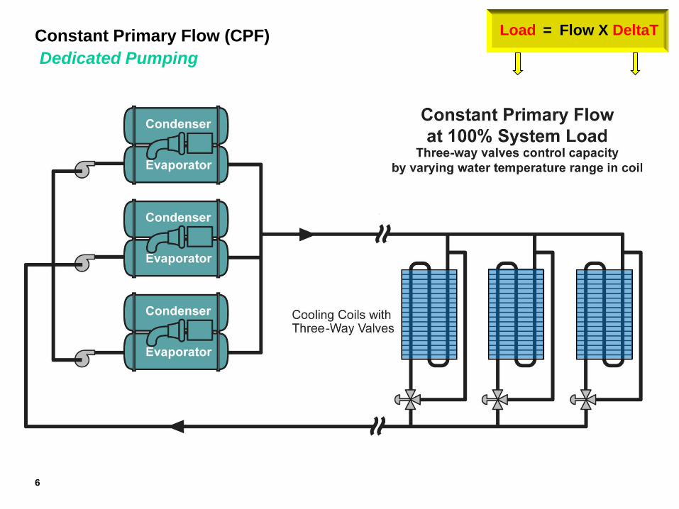
= Flow X DeltaT Load Constant Primary Flow (CPF)
Dedicated Pumping
6
Secondary Pumps
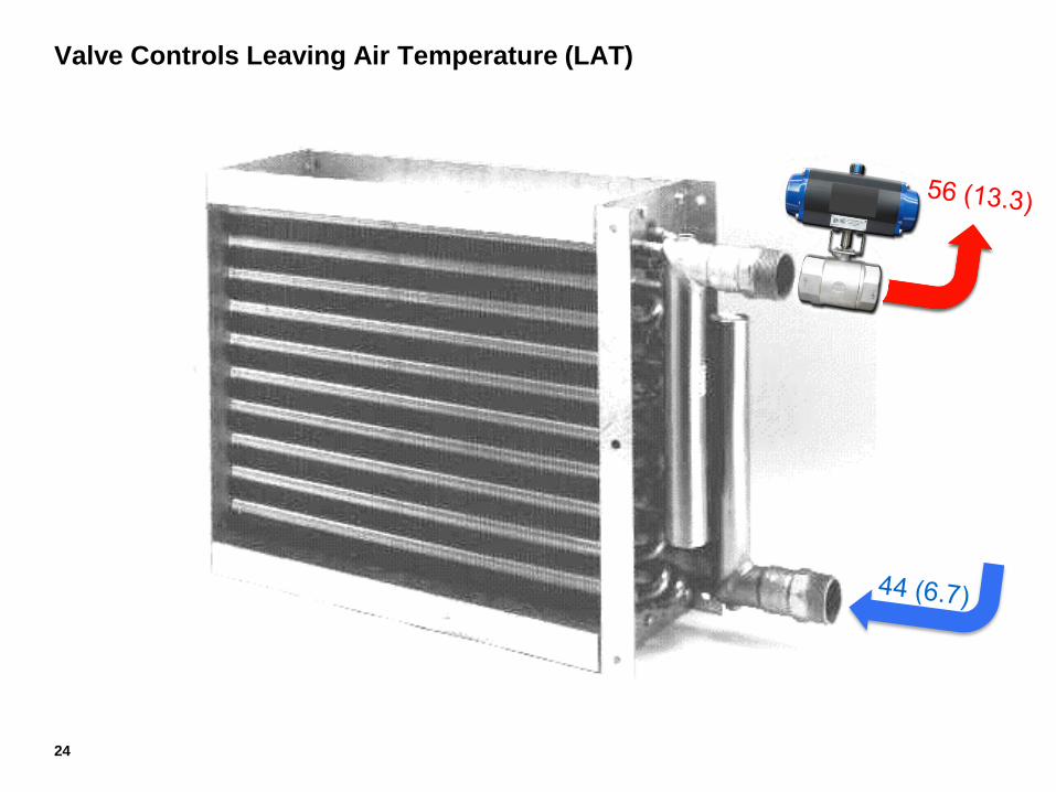
56 ºF
(13.3 ºC)
56 ºF
(13.3 ºC)
56 ºF
(13.3 ºC)
(63 l/s) 44 ºF
(6.7 ºC)
(189 l/s) @ 6.7 ºC)
(1760 kW)
(189 l/s) @ 13.3 ºC)
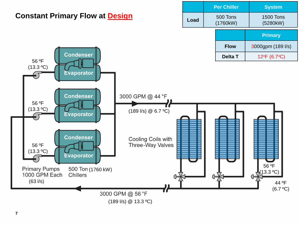
Constant Primary Flow at Design
7
Primary
Flow 3000gpm (189 l/s)
Delta T 12oF (6.7oC)
Per Chiller System
Load 500 Tons
(1760kW)
1500 Tons
(5280kW)
56 ºF
(13.3 ºC)
Secondary Pumps
53 ºF
(11.7 ºC)
53 ºF
(11.7 ºC)
53 ºF
(11.7 ºC)
(63 l/s)
(1760 kW)
53 ºF
(11.7 ºC)
75%
(189 l/s) @ 11.7 ºC)
53 ºF
(189 l/s) @ 6.7 ºC)
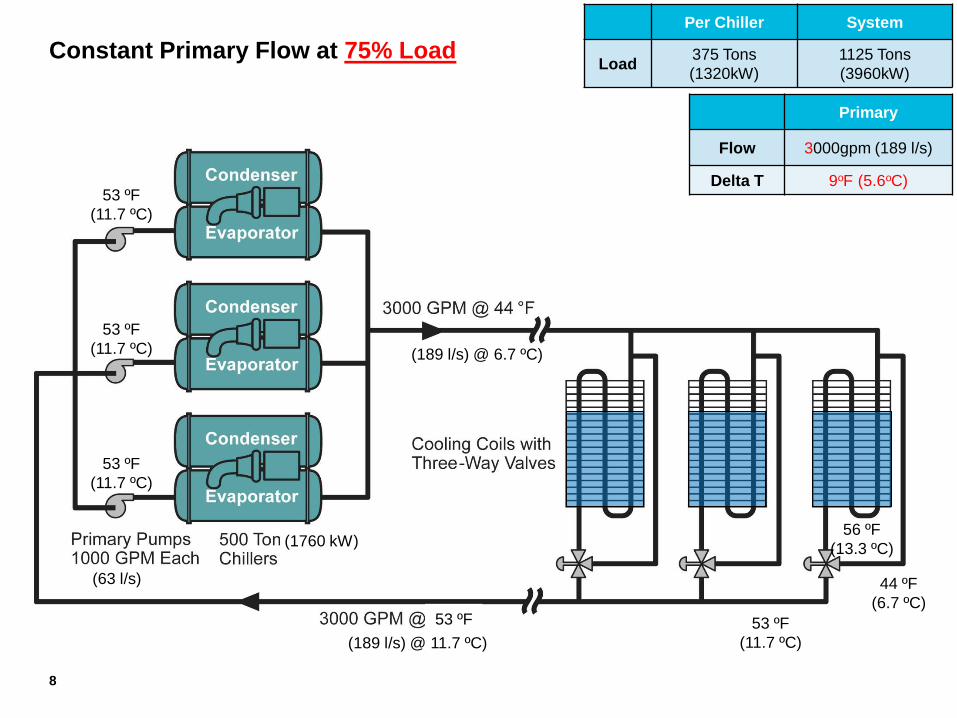
Constant Primary Flow at 75% Load
8
Primary
Flow 3000gpm (189 l/s)
Delta T 9oF (5.6oC)
Per Chiller System
Load 375 Tons
(1320kW)
1125 Tons
(3960kW)
44 ºF
(6.7 ºC)
56 ºF
(13.3 ºC)
Secondary Pumps
50 ºF
(10 ºC)
50 ºF
(10 ºC)
50 ºF
(10 ºC)
(63 l/s)
(1760 kW)
50 ºF
(10 ºC)
50%
(189 l/s) @ 10 ºC)
50 ºF
(189 l/s) @ 6.7 ºC)
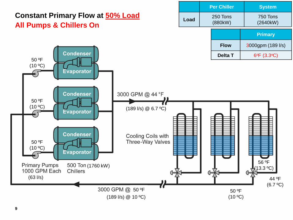
Constant Primary Flow at 50% Load
All Pumps & Chillers On
9
Primary
Flow 3000gpm (189 l/s)
Delta T 6oF (3.3oC)
Per Chiller System
Load 250 Tons
(880kW)
750 Tons
(2640kW)
44 ºF
(6.7 ºC)
56 ºF
(13.3 ºC)
Secondary Pumps
53 ºF
(11.7 ºC)
53 ºF
(11.7 ºC)
53 ºF
(11.7 ºC)
(63 l/s)
(1760 kW)
53 ºF
(11.7 ºC)
50%
(189 l/s) @ 11.7 ºC)
53 ºF
(189 l/s) @ 8.8 ºC)
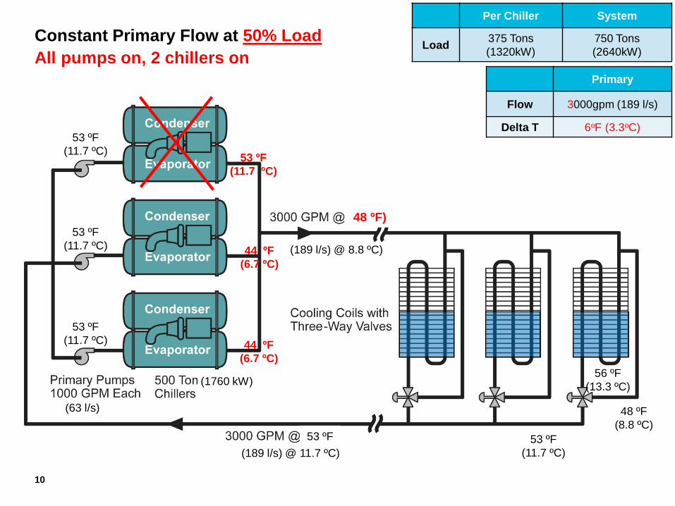
Constant Primary Flow at 50% Load
All pumps on, 2 chillers on
10
Primary
Flow 3000gpm (189 l/s)
Delta T 6oF (3.3oC)
Per Chiller System
Load 375 Tons
(1320kW)
750 Tons
(2640kW)
48 ºF
(8.8 ºC)
56 ºF
(13.3 ºC)
48 ºF)
53 ºF
(11.7 ºC)
44 ºF
(6.7 ºC)
44 ºF
(6.7 ºC)
Secondary Pumps
50 ºF
(11.7 ºC)
50 ºF
(11.7 ºC)
50 ºF
(11.7 ºC)
(63 l/s)
(1760 kW)
50 ºF
(11.7 ºC)
50%
(189 l/s) @ 11.7 ºC)
50 ºF
(189 l/s) @ 6.7 ºC)
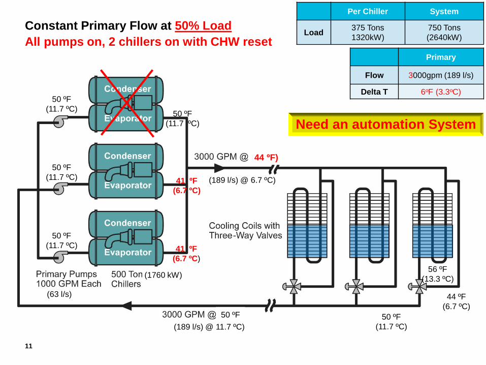
Constant Primary Flow at 50% Load
All pumps on, 2 chillers on with CHW reset
11
Primary
Flow 3000gpm (189 l/s)
Delta T 6oF (3.3oC)
Per Chiller System
Load 375 Tons
1320kW)
750 Tons
(2640kW)
44 ºF
(6.7 ºC)
56 ºF
(13.3 ºC)
44 ºF)
50 ºF
(11.7 ºC)
41 ºF
(6.7 ºC)
41 ºF
(6.7 ºC)
Need an automation System
Secondary Pumps
47 ºF
(8.3 ºC)
47 ºF
(8.3 ºC)
47 ºF
(8.3ºC)
(63 l/s)
(1760 kW)
47 ºF
(8.3 ºC)
25%
(189 l/s) @ 8.3 ºC)
47 ºF
(189 l/s) @ 6.7 ºC)
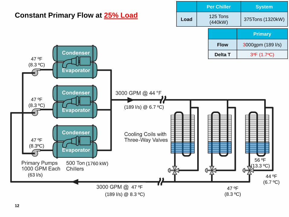
Constant Primary Flow at 25% Load
12
Primary
Flow 3000gpm (189 l/s)
Delta T 3oF (1.7oC)
Per Chiller System
Load 125 Tons
(440kW) 375Tons (1320kW)
44 ºF
(6.7 ºC)
56 ºF
(13.3 ºC)
Advantages
Lowest installed cost
Less plant space than P/S
Easy to Control & Operate
Easy to Commission
Disadvantages
Highest Plant Energy Cost (all pumps on always, possibly chillers as well)
Constant Flow Primary
13
Primary (Constant) / Secondary (Variable)
14
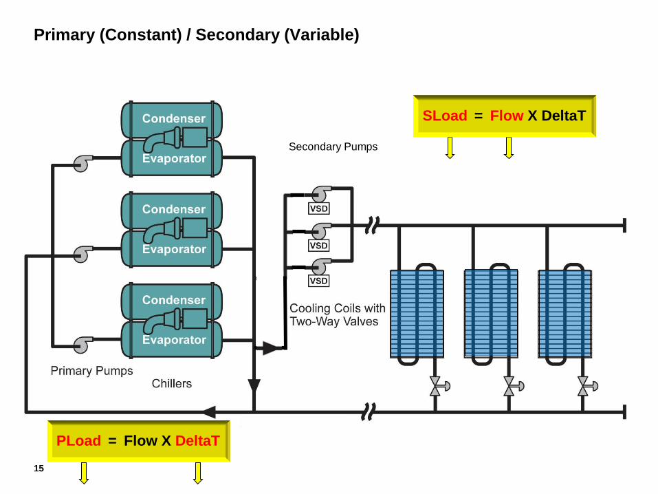
Primary (Constant) / Secondary (Variable)
Secondary Pumps
= Flow X DeltaT PLoad
15
= Flow X DeltaT SLoad
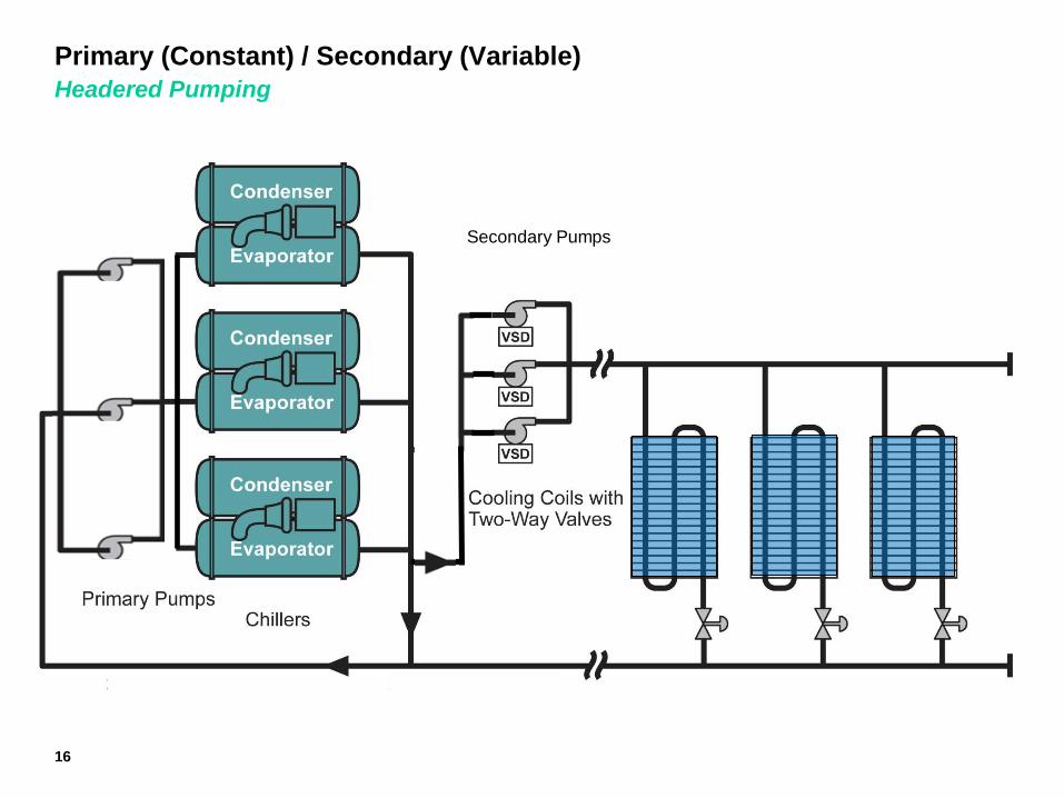
Primary (Constant) / Secondary (Variable)
Headered Pumping
Secondary Pumps
16
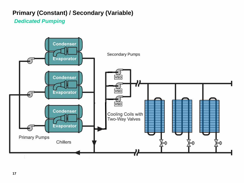
Primary (Constant) / Secondary (Variable)
Dedicated Pumping
Secondary Pumps
17
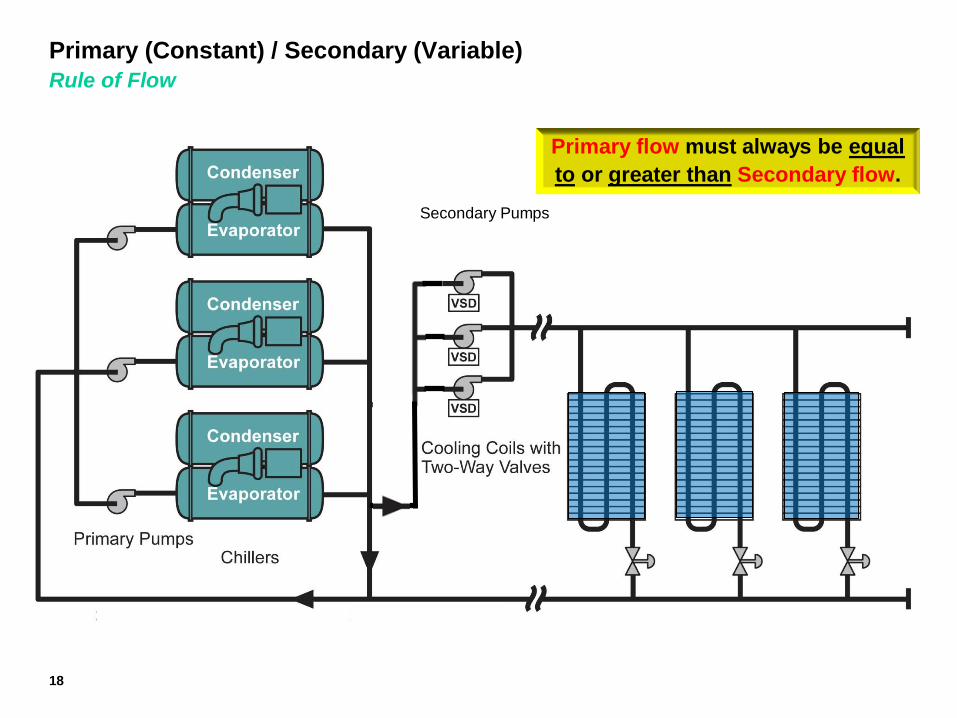
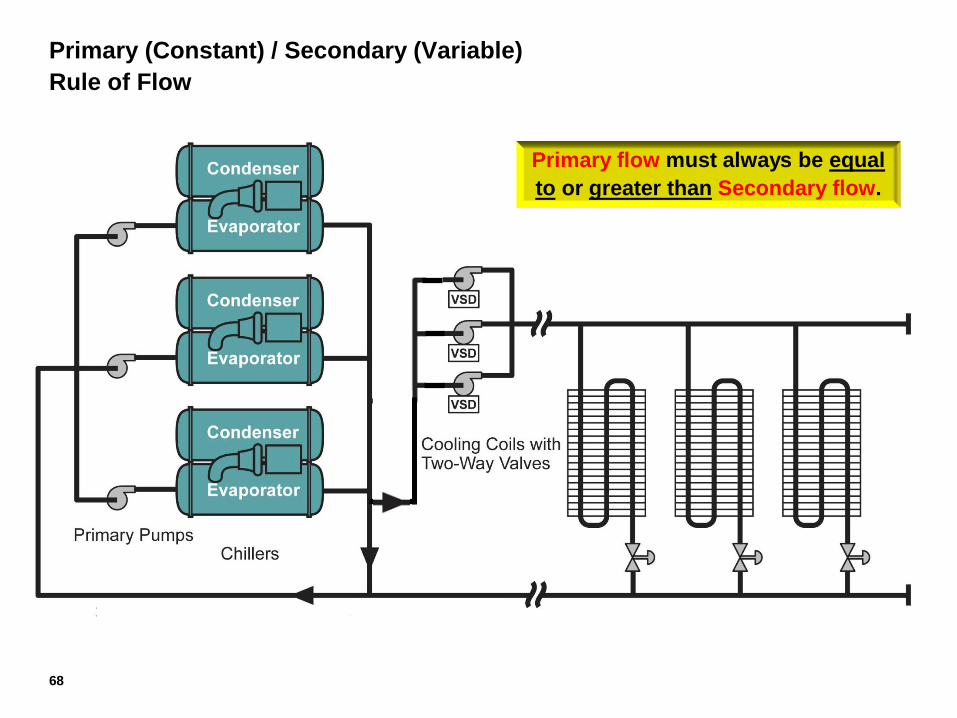
Primary (Constant) / Secondary (Variable)
Rule of Flow
18
Secondary Pumps
Primary flow must always be equal
to or greater than Secondary flow.
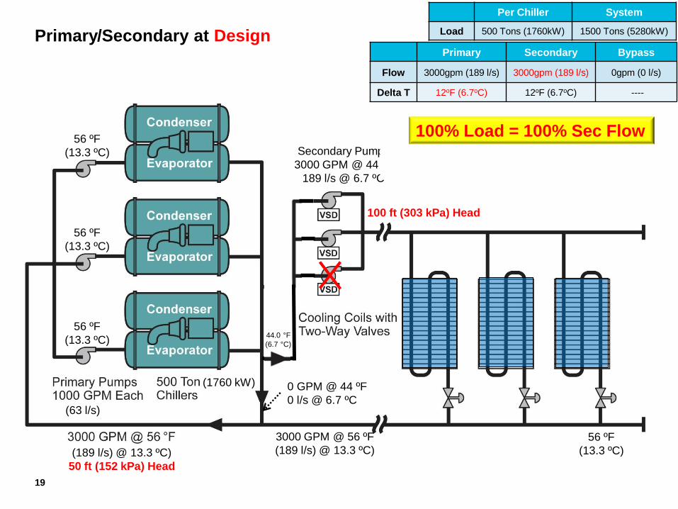
Primary/Secondary at Design
(63 l/s)
(1760 kW)
Secondary Pumps
3000 GPM @ 44 ºF
189 l/s @ 6.7 ºC
56 ºF
(13.3 ºC)
56 ºF
(13.3 ºC)
56 ºF
(13.3 ºC)
56 ºF
(13.3 ºC) (189 l/s) @ 13.3 ºC)
50 ft (152 kPa) Head
Per Chiller System
Load 500 Tons (1760kW) 1500 Tons (5280kW)
Primary Secondary Bypass
Flow 3000gpm (189 l/s) 3000gpm (189 l/s) 0gpm (0 l/s)
Delta T 12oF (6.7oC) 12oF (6.7oC) ----
0 GPM @ 44 ºF
0 l/s @ 6.7 ºC
3000 GPM @ 56 ºF
(189 l/s) @ 13.3 ºC)
44.0 °F
(6.7 °C)
100 ft (303 kPa) Head
19
100% Load = 100% Sec Flow
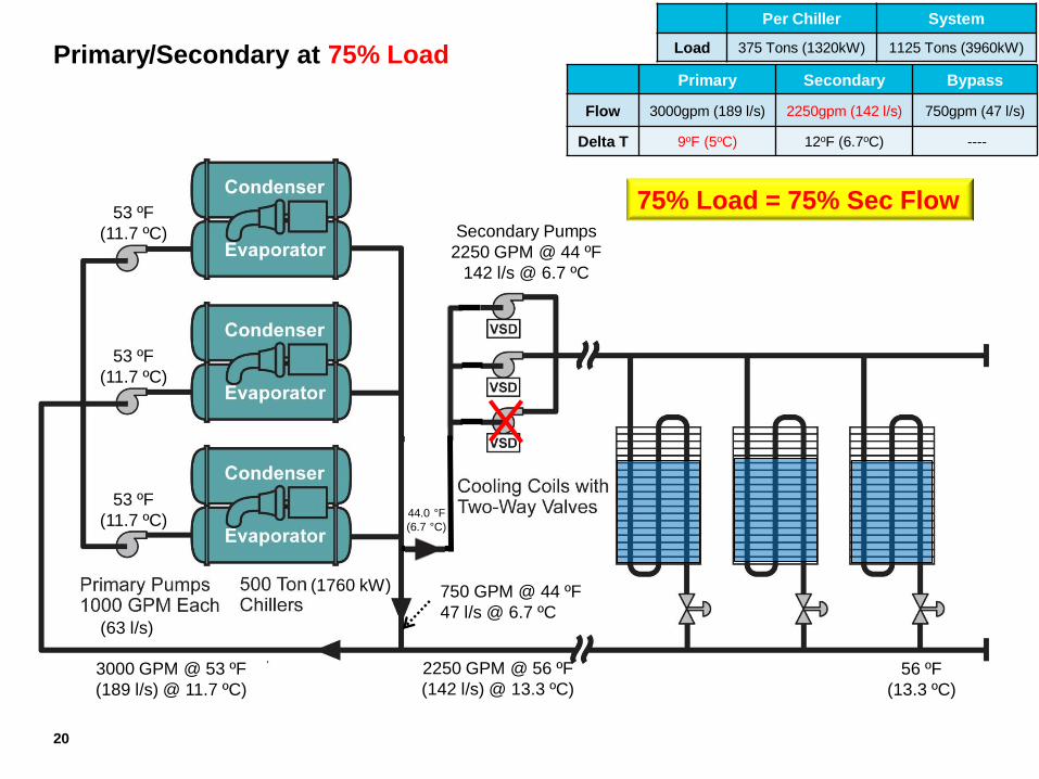
Primary/Secondary at 75% Load
(63 l/s)
(1760 kW)
Secondary Pumps
2250 GPM @ 44 ºF
142 l/s @ 6.7 ºC
53 ºF
(11.7 ºC)
53 ºF
(11.7 ºC)
53 ºF
(11.7 ºC)
56 ºF
(13.3 ºC)
Per Chiller System
Load 375 Tons (1320kW) 1125 Tons (3960kW)
Primary Secondary Bypass
Flow 3000gpm (189 l/s) 2250gpm (142 l/s) 750gpm (47 l/s)
Delta T 9oF (5oC) 12oF (6.7oC) ----
750 GPM @ 44 ºF
47 l/s @ 6.7 ºC
75%
2250 GPM @ 56 ºF
(142 l/s) @ 13.3 ºC)
3000 GPM @ 53 ºF
(189 l/s) @ 11.7 ºC)
44.0 °F
(6.7 °C)
20
75% Load = 75% Sec Flow
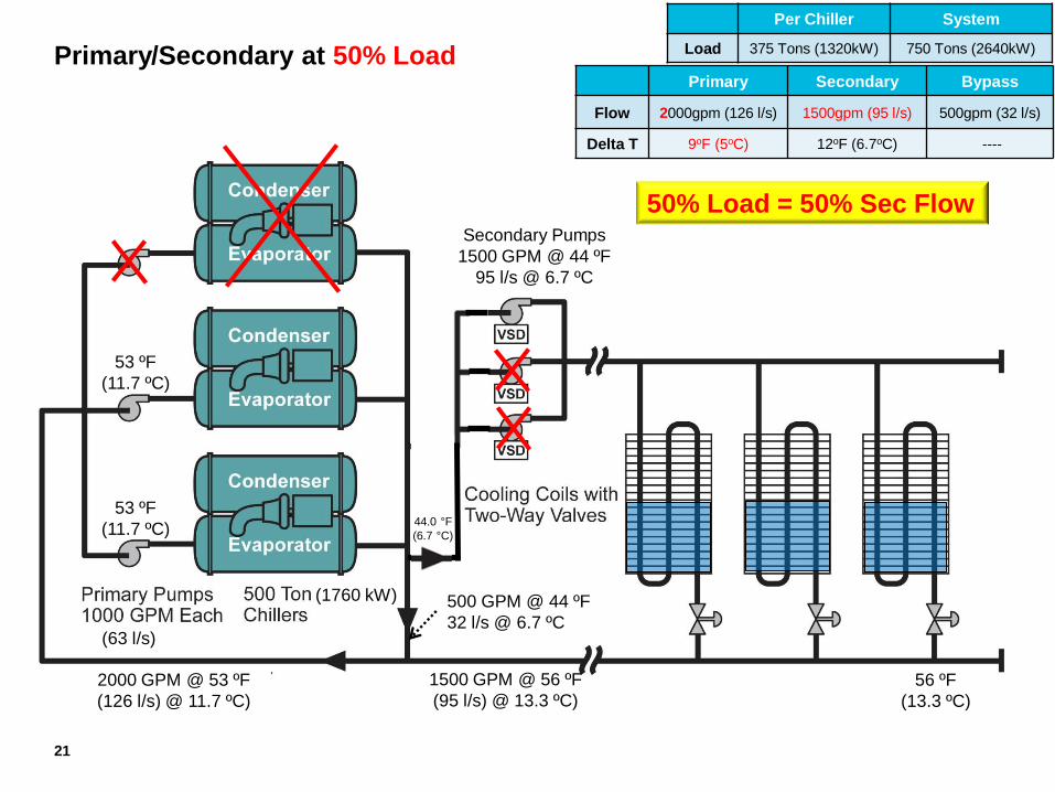
Primary/Secondary at 50% Load
(63 l/s)
(1760 kW)
Secondary Pumps
1500 GPM @ 44 ºF
95 l/s @ 6.7 ºC
53 ºF
(11.7 ºC)
53 ºF
(11.7 ºC)
56 ºF
(13.3 ºC)
Per Chiller System
Load 375 Tons (1320kW) 750 Tons (2640kW)
Primary Secondary Bypass
Flow 2000gpm (126 l/s) 1500gpm (95 l/s) 500gpm (32 l/s)
Delta T 9oF (5oC) 12oF (6.7oC) ----
500 GPM @ 44 ºF
32 l/s @ 6.7 ºC
50%
1500 GPM @ 56 ºF
(95 l/s) @ 13.3 ºC)
2000 GPM @ 53 ºF
(126 l/s) @ 11.7 ºC)
44.0 °F
(6.7 °C)
21
50% Load = 50% Sec Flow
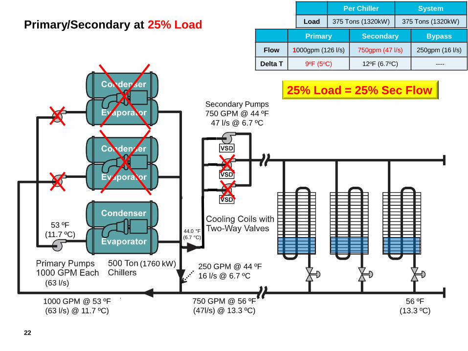
Primary/Secondary at 25% Load
(63 l/s)
(1760 kW)
Secondary Pumps
750 GPM @ 44 ºF
47 l/s @ 6.7 ºC
53 ºF
(11.7 ºC)
56 ºF
(13.3 ºC)
Per Chiller System
Load 375 Tons (1320kW) 375 Tons (1320kW)
Primary Secondary Bypass
Flow 1000gpm (126 l/s) 750gpm (47 l/s) 250gpm (16 l/s)
Delta T 9oF (5oC) 12oF (6.7oC) ----
250 GPM @ 44 ºF
16 l/s @ 6.7 ºC
25%
750 GPM @ 56 ºF
(47l/s) @ 13.3 ºC)
1000 GPM @ 53 ºF
(63 l/s) @ 11.7 ºC)
44.0 °F
(6.7 °C)
22
25% Load = 25% Sec Flow
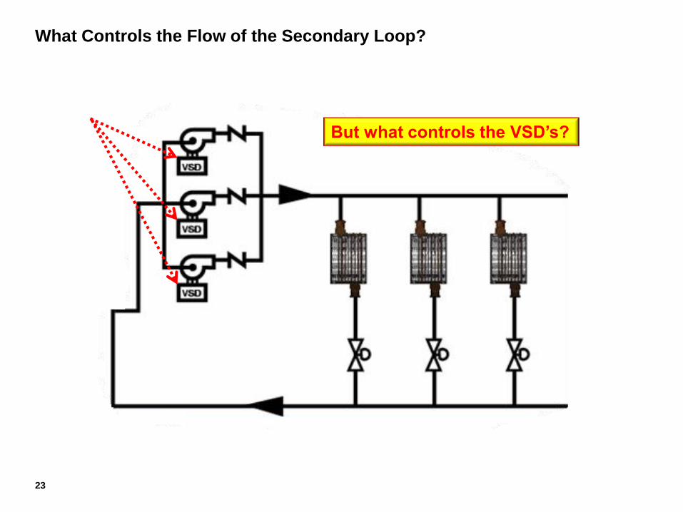
But what controls the VSD’s?
23
What Controls the Flow of the Secondary Loop?
24
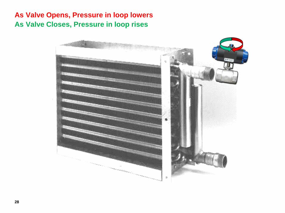
Valve Controls Leaving Air Temperature (LAT)
25
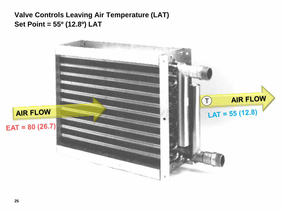
Valve Controls Leaving Air Temperature (LAT)
Set Point = 55º (12.8º) LAT
T
26
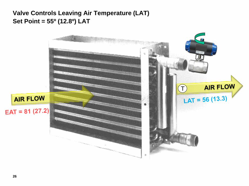
Valve Controls Leaving Air Temperature (LAT)
Set Point = 55º (12.8º) LAT
T
27
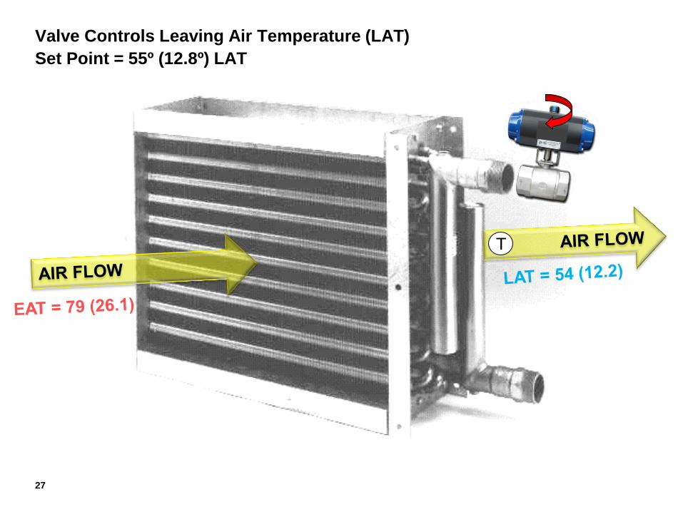
Valve Controls Leaving Air Temperature (LAT)
Set Point = 55º (12.8º) LAT
T
28
As Valve Opens, Pressure in loop lowers
As Valve Closes, Pressure in loop rises
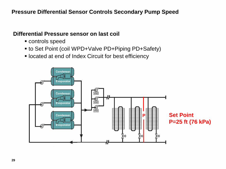
Pressure Differential Sensor Controls Secondary Pump Speed
Differential Pressure sensor on last coil
controls speed
to Set Point (coil WPD+Valve PD+Piping PD+Safety)
located at end of Index Circuit for best efficiency
Set Point
P=25 ft (76 kPa)
P
29
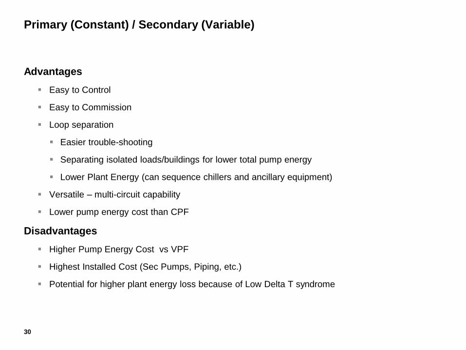
Advantages
Easy to Control
Easy to Commission
Loop separation
Easier trouble-shooting
Separating isolated loads/buildings for lower total pump energy
Lower Plant Energy (can sequence chillers and ancillary equipment)
Versatile – multi-circuit capability
Lower pump energy cost than CPF
Disadvantages
Higher Pump Energy Cost vs VPF
Highest Installed Cost (Sec Pumps, Piping, etc.)
Potential for higher plant energy loss because of Low Delta T syndrome
Primary (Constant) / Secondary (Variable)
30
Variable Primary Flow
31
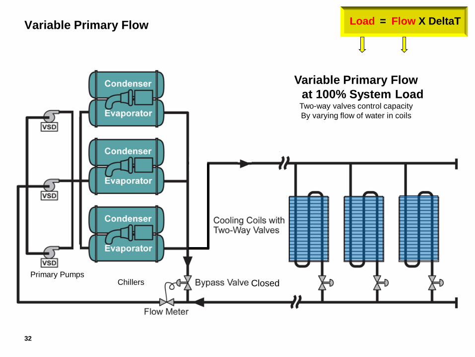
Variable Primary Flow
= Flow X DeltaT Load
Variable Primary Flow
at 100% System Load Two-way valves control capacity
By varying flow of water in coils
Primary Pumps
Chillers Closed
32
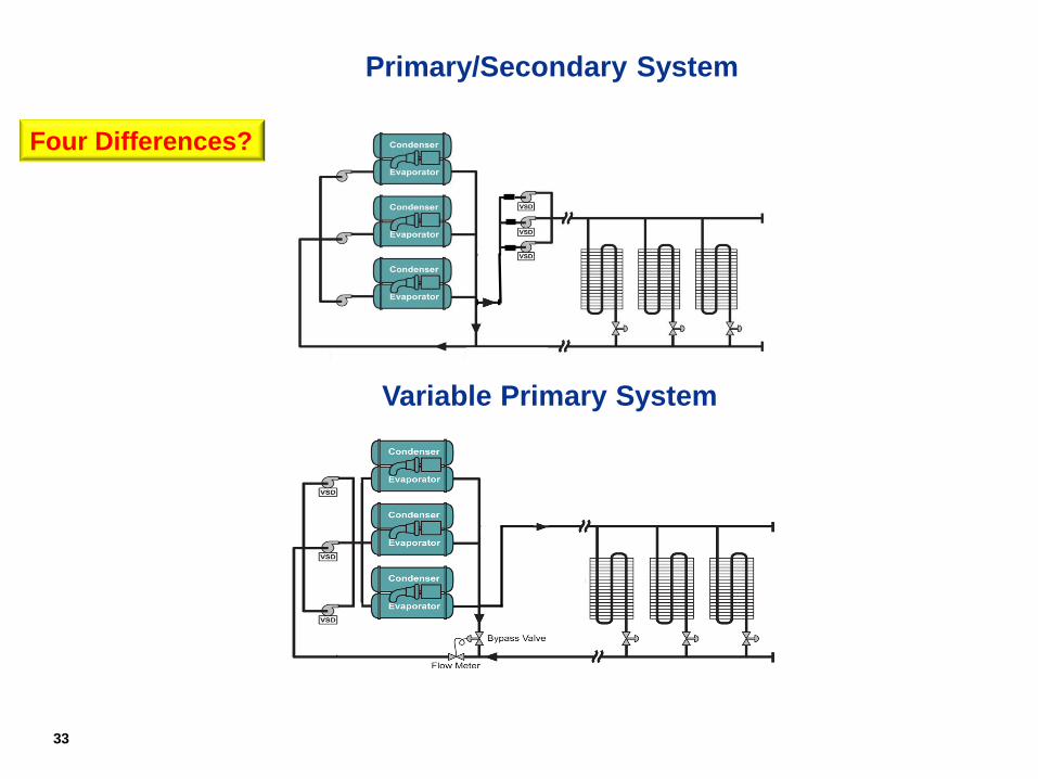
Primary/Secondary System
Variable Primary System
Primary
Pumps
Chillers
Four Differences?
33
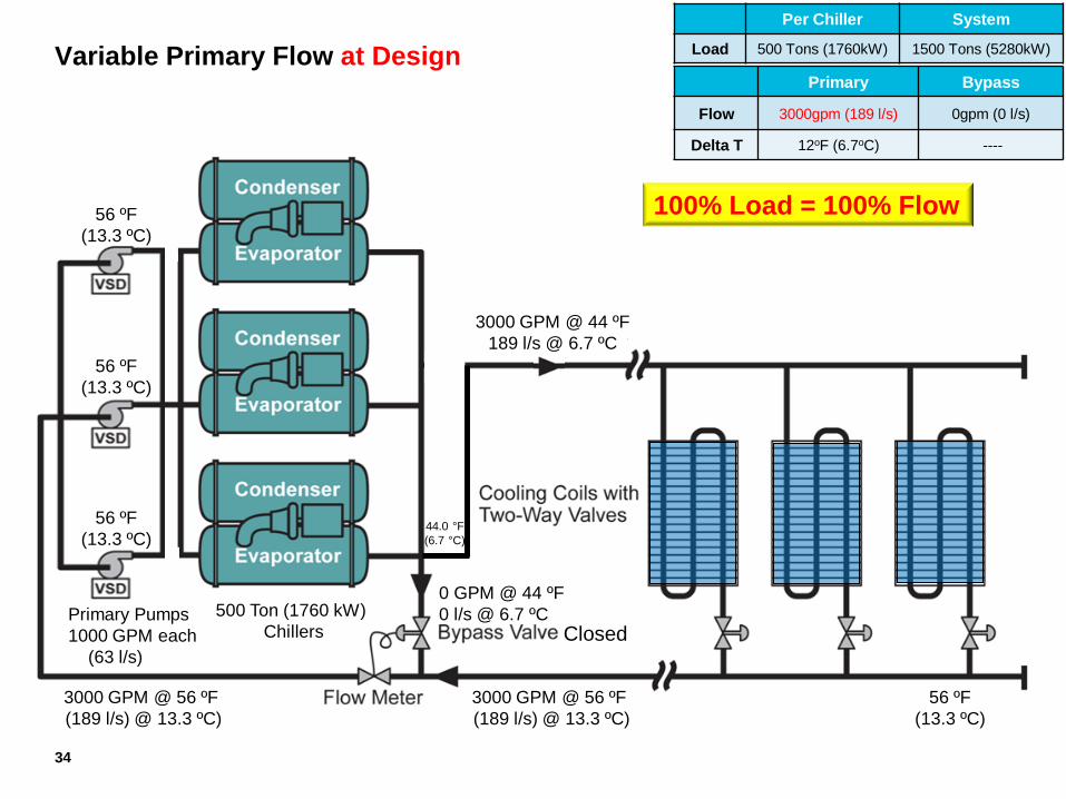
Variable Primary Flow at Design
Variable Primary Flow
at 100% System Load Two-way valves control capacity
By varying flow of water in coils
Per Chiller System
Load 500 Tons (1760kW) 1500 Tons (5280kW)
Primary Bypass
Flow 3000gpm (189 l/s) 0gpm (0 l/s)
Delta T 12oF (6.7oC) ----
56 ºF
(13.3 ºC)
0 GPM @ 44 ºF
0 l/s @ 6.7 ºC
3000 GPM @ 56 ºF
(189 l/s) @ 13.3 ºC)
44.0 °F
(6.7 °C)
3000 GPM @ 56 ºF
(189 l/s) @ 13.3 ºC)
Primary Pumps
1000 GPM each
(63 l/s)
500 Ton (1760 kW)
Chillers
3000 GPM @ 44 ºF
189 l/s @ 6.7 ºC
56 ºF
(13.3 ºC)
56 ºF
(13.3 ºC)
56 ºF
(13.3 ºC)
Closed
34
100% Load = 100% Flow
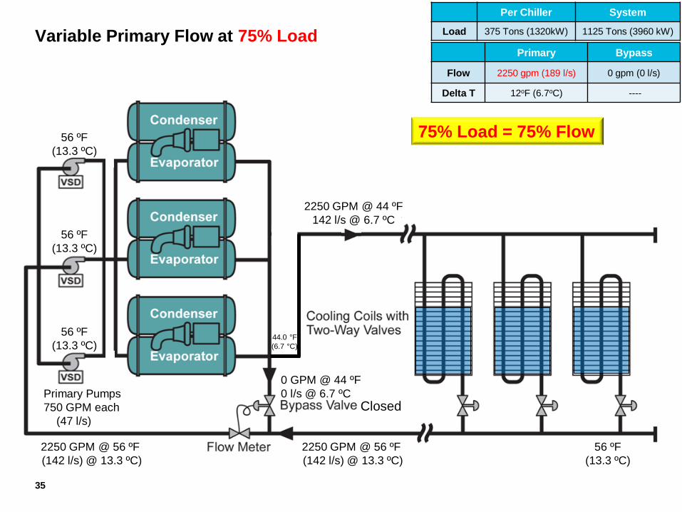
Variable Primary Flow at 75% Load
Variable Primary Flow
at 75% System Load Two-way valves control capacity
By varying flow of water in coils
Per Chiller System
Load 375 Tons (1320kW) 1125 Tons (3960 kW)
Primary Bypass
Flow 2250 gpm (189 l/s) 0 gpm (0 l/s)
Delta T 12oF (6.7oC) ----
56 ºF
(13.3 ºC)
0 GPM @ 44 ºF
0 l/s @ 6.7 ºC
2250 GPM @ 56 ºF
(142 l/s) @ 13.3 ºC)
44.0 °F
(6.7 °C)
2250 GPM @ 56 ºF
(142 l/s) @ 13.3 ºC)
Primary Pumps
750 GPM each
(47 l/s)
2250 GPM @ 44 ºF
142 l/s @ 6.7 ºC
56 ºF
(13.3 ºC)
56 ºF
(13.3 ºC)
56 ºF
(13.3 ºC)
Closed
35
75% Load = 75% Flow
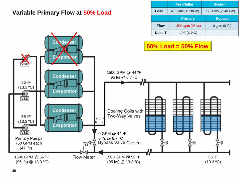
Variable Primary Flow at 50% Load
Variable Primary Flow
at 50% System Load Two-way valves control capacity
By varying flow of water in coils
Per Chiller System
Load 375 Tons (1320kW) 750 Tons (2640 kW)
Primary Bypass
Flow 1500 gpm (95 l/s) 0 gpm (0 l/s)
Delta T 12oF (6.7oC) ----
56 ºF
(13.3 ºC)
0 GPM @ 44 ºF
0 l/s @ 6.7 ºC
1500 GPM @ 56 ºF
(95 l/s) @ 13.3 ºC)
44.0 °F
(6.7 °C)
1500 GPM @ 56 ºF
(95 l/s) @ 13.3 ºC)
Primary Pumps
750 GPM each
(47 l/s)
1500 GPM @ 44 ºF
95 l/s @ 6.7 ºC
56 ºF
(13.3 ºC)
56 ºF
(13.3 ºC)
Closed
36
50% Load = 50% Flow
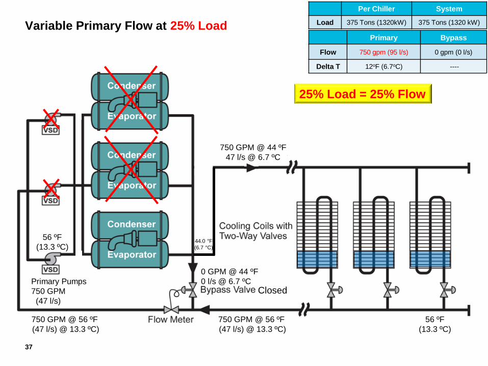
Variable Primary Flow at 25% Load
Variable Primary Flow
at 25% System Load Two-way valves control capacity
By varying flow of water in coils
Per Chiller System
Load 375 Tons (1320kW) 375 Tons (1320 kW)
Primary Bypass
Flow 750 gpm (95 l/s) 0 gpm (0 l/s)
Delta T 12oF (6.7oC) ----
56 ºF
(13.3 ºC)
0 GPM @ 44 ºF
0 l/s @ 6.7 ºC
750 GPM @ 56 ºF
(47 l/s) @ 13.3 ºC)
44.0 °F
(6.7 °C)
750 GPM @ 56 ºF
(47 l/s) @ 13.3 ºC)
Primary Pumps
750 GPM
(47 l/s)
750 GPM @ 44 ºF
47 l/s @ 6.7 ºC
56 ºF
(13.3 ºC)
Closed
37
25% Load = 25% Flow
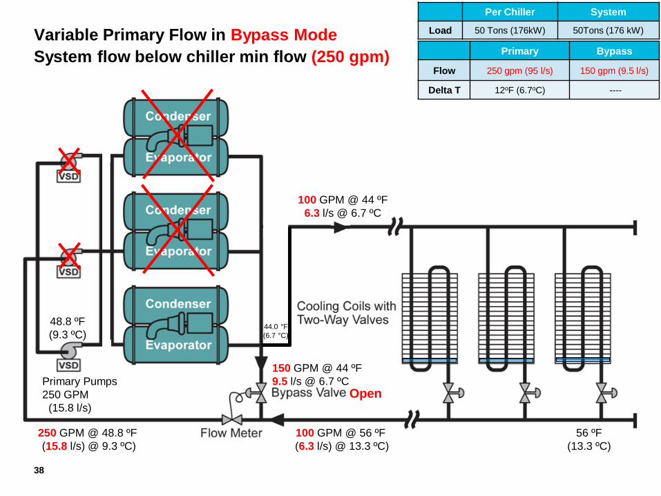
Variable Primary Flow in Bypass Mode
System flow below chiller min flow (250 gpm)
Variable Primary Flow
at 25% System Load Two-way valves control capacity
By varying flow of water in coils
Per Chiller System
Load 50 Tons (176kW) 50Tons (176 kW)
Primary Bypass
Flow 250 gpm (95 l/s) 150 gpm (9.5 l/s)
Delta T 12oF (6.7oC) ----
56 ºF
(13.3 ºC)
150 GPM @ 44 ºF
9.5 l/s @ 6.7 ºC
100 GPM @ 56 ºF
(6.3 l/s) @ 13.3 ºC)
44.0 °F
(6.7 °C)
250 GPM @ 48.8 ºF
(15.8 l/s) @ 9.3 ºC)
Primary Pumps
250 GPM
(15.8 l/s)
100 GPM @ 44 ºF
6.3 l/s @ 6.7 ºC
Open
48.8 ºF
(9.3 ºC)
38
39
Varying Flow Through Chillers - Issues
Issue 1 - During Normal Operation
Chiller Type (centrifugal fast, absorbers slow)
Chiller Load (min load - no variance, full load - max variance)
System Water Volume (more water, more thermal capacitance, faster variance allowed)
Active Loads (near or far from plant)
Typical VSD pump ramp rate setting of 10%/minute (accel/decel rates set to 600 seconds)
39
40
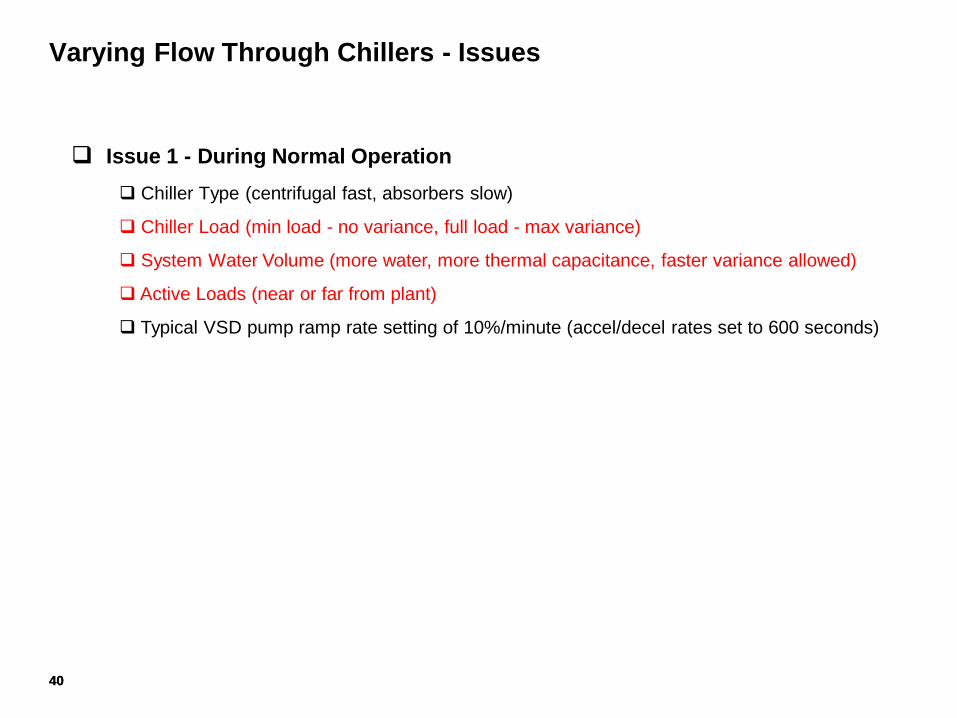
Varying Flow Through Chillers - Issues
Issue 1 - During Normal Operation
Chiller Type (centrifugal fast, absorbers slow)
Chiller Load (min load - no variance, full load - max variance)
System Water Volume (more water, more thermal capacitance, faster variance allowed)
Active Loads (near or far from plant)
Typical VSD pump ramp rate setting of 10%/minute (accel/decel rates set to 600 seconds)
40
41
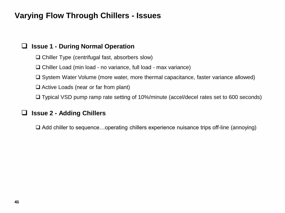
Varying Flow Through Chillers - Issues
Issue 1 - During Normal Operation
Chiller Type (centrifugal fast, absorbers slow)
Chiller Load (min load - no variance, full load - max variance)
System Water Volume (more water, more thermal capacitance, faster variance allowed)
Active Loads (near or far from plant)
Typical VSD pump ramp rate setting of 10%/minute (accel/decel rates set to 600 seconds)
Issue 2 - Adding Chillers
Add chiller to sequence…operating chillers experience nuisance trips off-line (annoying)
41
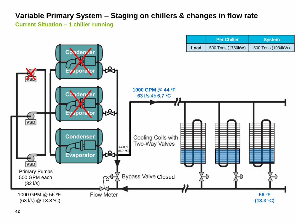
Variable Primary System – Staging on chillers & changes in flow rate Current Situation – 1 chiller running
Variable Primary Flow
at 100% System Load Two-way valves control capacity
By varying flow of water in coils
56 ºF
(13.3 ºC)
44.0 °F
(6.7 °C)
1000 GPM @ 56 ºF
(63 l/s) @ 13.3 ºC)
Primary Pumps
500 GPM each
(32 l/s)
1000 GPM @ 44 ºF
63 l/s @ 6.7 ºC
Closed
42
Per Chiller System
Load 500 Tons (1760kW) 500 Tons (1934kW)
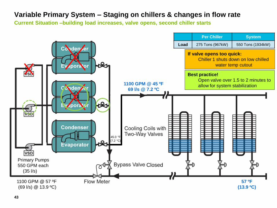
Variable Primary System – Staging on chillers & changes in flow rate Current Situation –building load increases, valve opens, second chiller starts
Variable Primary Flow
at 100% System Load Two-way valves control capacity
By varying flow of water in coils
57 ºF
(13.9 ºC)
45.0 °F
(7.2 °C)
1100 GPM @ 57 ºF
(69 l/s) @ 13.9 ºC)
Primary Pumps
550 GPM each
(35 l/s)
1100 GPM @ 45 ºF
69 l/s @ 7.2 ºC
Closed
43
Per Chiller System
Load 275 Tons (967kW) 550 Tons (1934kW)
If valve opens too quick:
Chiller 1 shuts down on low chilled
water temp cutout
Best practice!
Open valve over 1.5 to 2 minutes to
allow for system stabilization
Advantages
Lower Installed Cost (approx. 5% compared P/S)
No secondary Pumps or piping, valves, electrical, installation, etc.
Offset somewhat by added 2W Bypass Valve and more complex controls
Less Plant Space Needed
Best Chilled Water Pump Energy Consumption (most optimeady configuration)
VSD energy savings
Lower Pump Design Head
Variable Primary Flow (VPF) System Arrangement
44
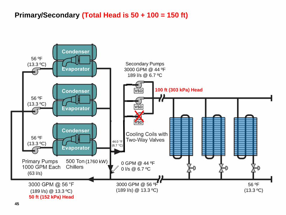
Primary/Secondary (Total Head is 50 + 100 = 150 ft)
(63 l/s)
(1760 kW)
Secondary Pumps
3000 GPM @ 44 ºF
189 l/s @ 6.7 ºC
56 ºF
(13.3 ºC)
56 ºF
(13.3 ºC)
56 ºF
(13.3 ºC)
56 ºF
(13.3 ºC) (189 l/s) @ 13.3 ºC)
50 ft (152 kPa) Head
0 GPM @ 44 ºF
0 l/s @ 6.7 ºC
3000 GPM @ 56 ºF
(189 l/s) @ 13.3 ºC)
44.0 °F
(6.7 °C)
100 ft (303 kPa) Head
45
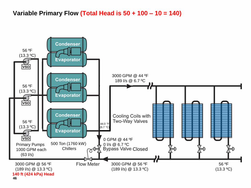
Variable Primary Flow (Total Head is 50 + 100 – 10 = 140)
Variable Primary Flow
at 100% System Load Two-way valves control capacity
By varying flow of water in coils
56 ºF
(13.3 ºC)
0 GPM @ 44 ºF
0 l/s @ 6.7 ºC
3000 GPM @ 56 ºF
(189 l/s) @ 13.3 ºC)
44.0 °F
(6.7 °C)
3000 GPM @ 56 ºF
(189 l/s) @ 13.3 ºC)
140 ft (424 kPa) Head
Primary Pumps
1000 GPM each
(63 l/s)
500 Ton (1760 kW)
Chillers
3000 GPM @ 44 ºF
189 l/s @ 6.7 ºC
56 ºF
(13.3 ºC)
56 ºF
(13.3 ºC)
56 ºF
(13.3 ºC)
Closed
46
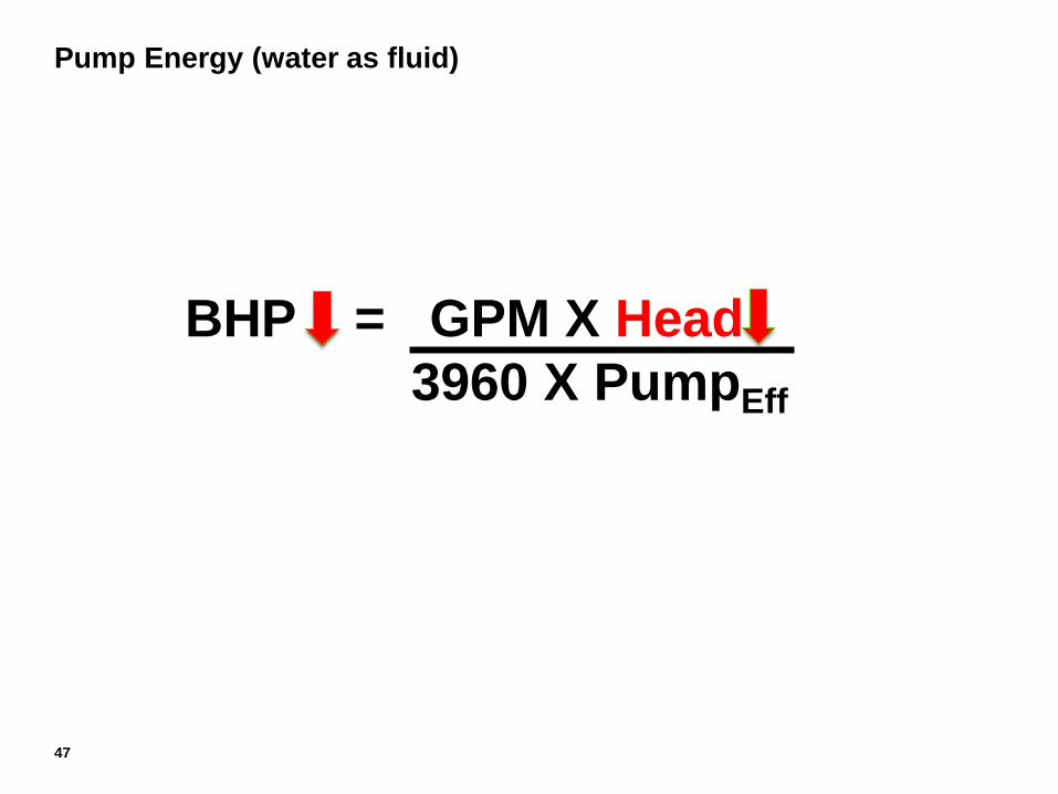
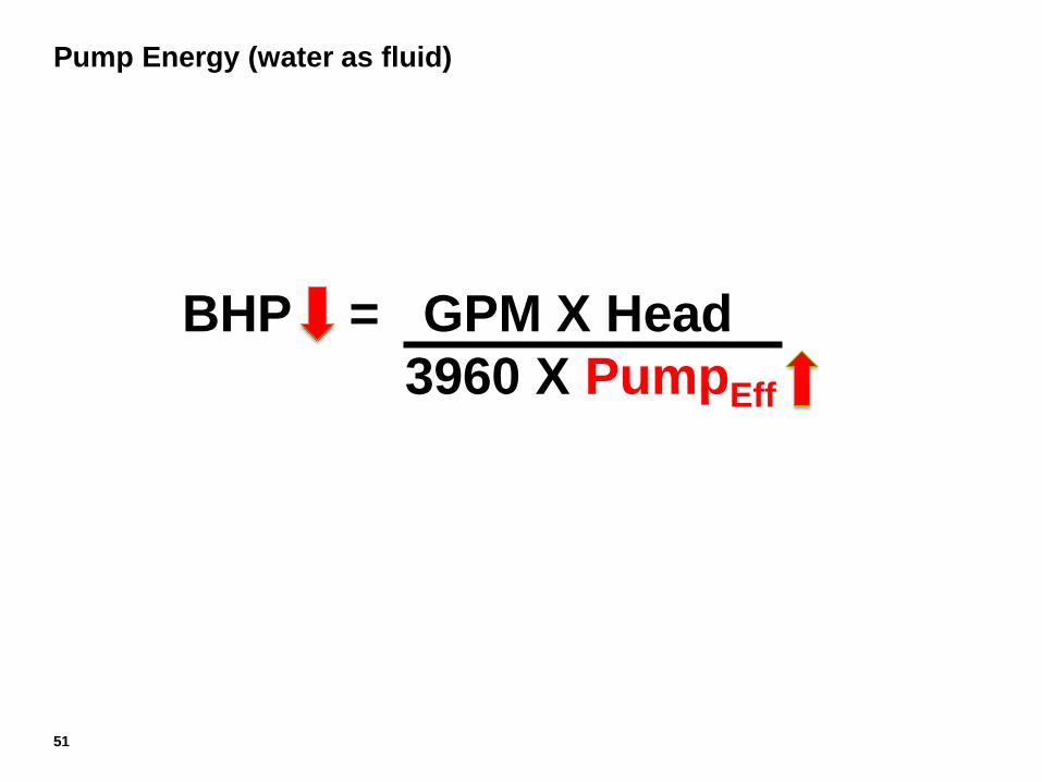
Pump Energy (water as fluid)
47
BHP = GPM X Head
3960 X PumpEff
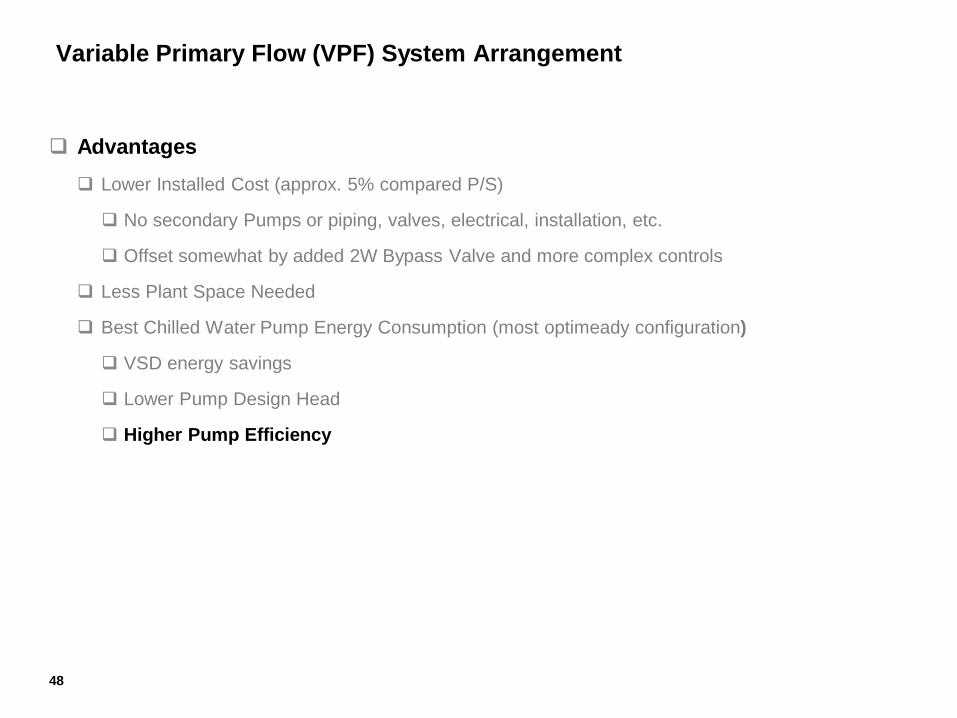
Advantages
Lower Installed Cost (approx. 5% compared P/S)
No secondary Pumps or piping, valves, electrical, installation, etc.
Offset somewhat by added 2W Bypass Valve and more complex controls
Less Plant Space Needed
Best Chilled Water Pump Energy Consumption (most optimeady configuration)
VSD energy savings
Lower Pump Design Head
Higher Pump Efficiency
Variable Primary Flow (VPF) System Arrangement
48
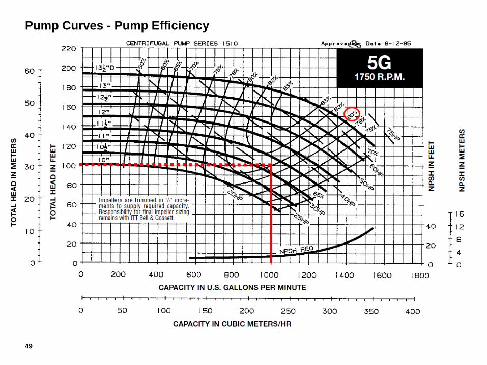
Pump Curves - Pump Efficiency
49
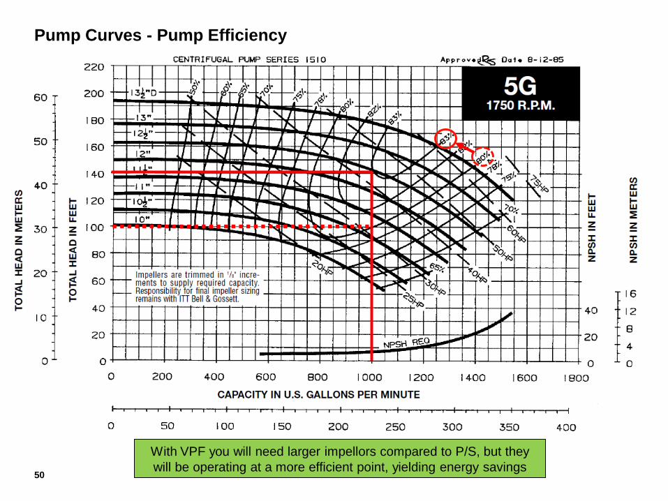
Pump Curves - Pump Efficiency
With VPF you will need larger impellors compared to P/S, but they
will be operating at a more efficient point, yielding energy savings 50
Pump Energy (water as fluid)
51
BHP = GPM X Head
3960 X PumpEff
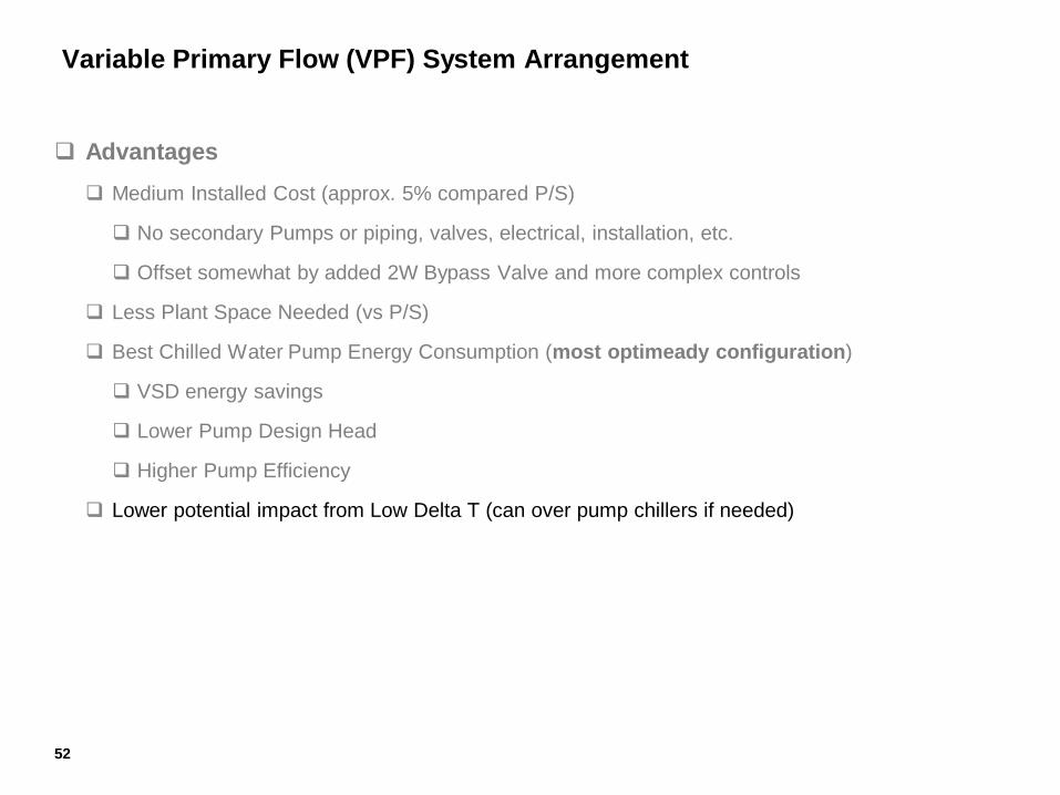
Advantages
Medium Installed Cost (approx. 5% compared P/S)
No secondary Pumps or piping, valves, electrical, installation, etc.
Offset somewhat by added 2W Bypass Valve and more complex controls
Less Plant Space Needed (vs P/S)
Best Chilled Water Pump Energy Consumption (most optimeady configuration)
VSD energy savings
Lower Pump Design Head
Higher Pump Efficiency
Lower potential impact from Low Delta T (can over pump chillers if needed)
Variable Primary Flow (VPF) System Arrangement
52
Advantages
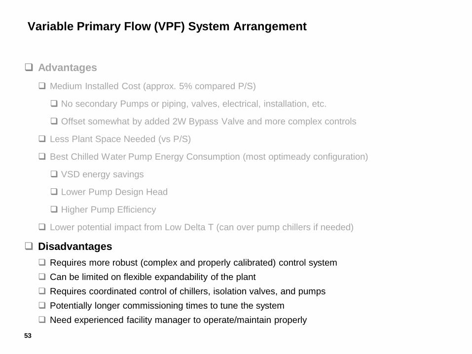
Medium Installed Cost (approx. 5% compared P/S)
No secondary Pumps or piping, valves, electrical, installation, etc.
Offset somewhat by added 2W Bypass Valve and more complex controls
Less Plant Space Needed (vs P/S)
Best Chilled Water Pump Energy Consumption (most optimeady configuration)
VSD energy savings
Lower Pump Design Head
Higher Pump Efficiency
Lower potential impact from Low Delta T (can over pump chillers if needed)
Disadvantages
Requires more robust (complex and properly calibrated) control system
Can be limited on flexible expandability of the plant
Requires coordinated control of chillers, isolation valves, and pumps
Potentially longer commissioning times to tune the system
Need experienced facility manager to operate/maintain properly
Variable Primary Flow (VPF) System Arrangement
53
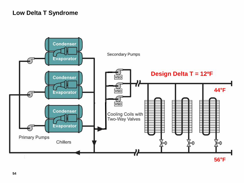
Low Delta T Syndrome
Secondary Pumps
54
44°F
56°F
Design Delta T = 12ºF
Major Causes of Low Delta T
Dirty Coils
55
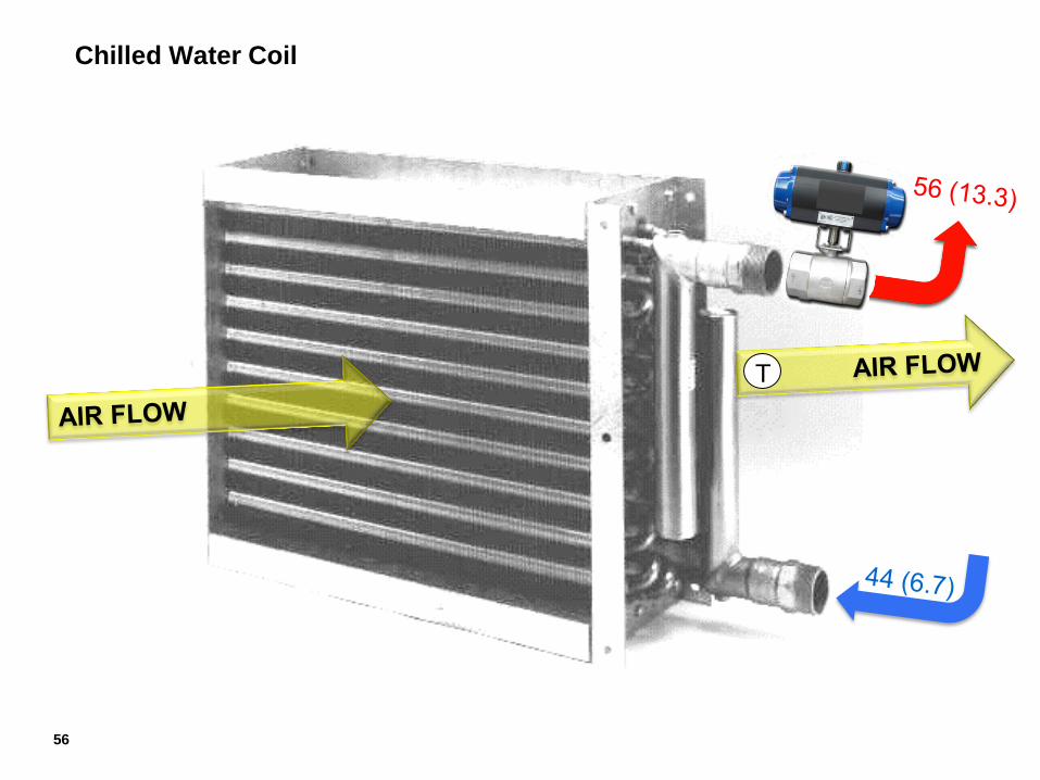
Chilled Water Coil
T
56
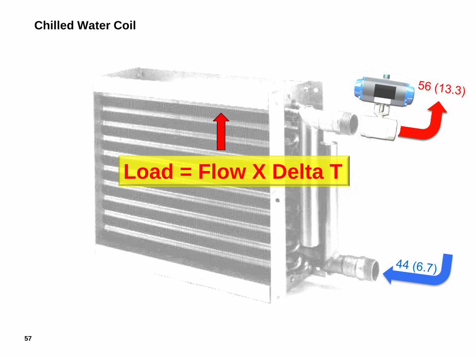
Chilled Water Coil
Load = Flow X Delta T
57
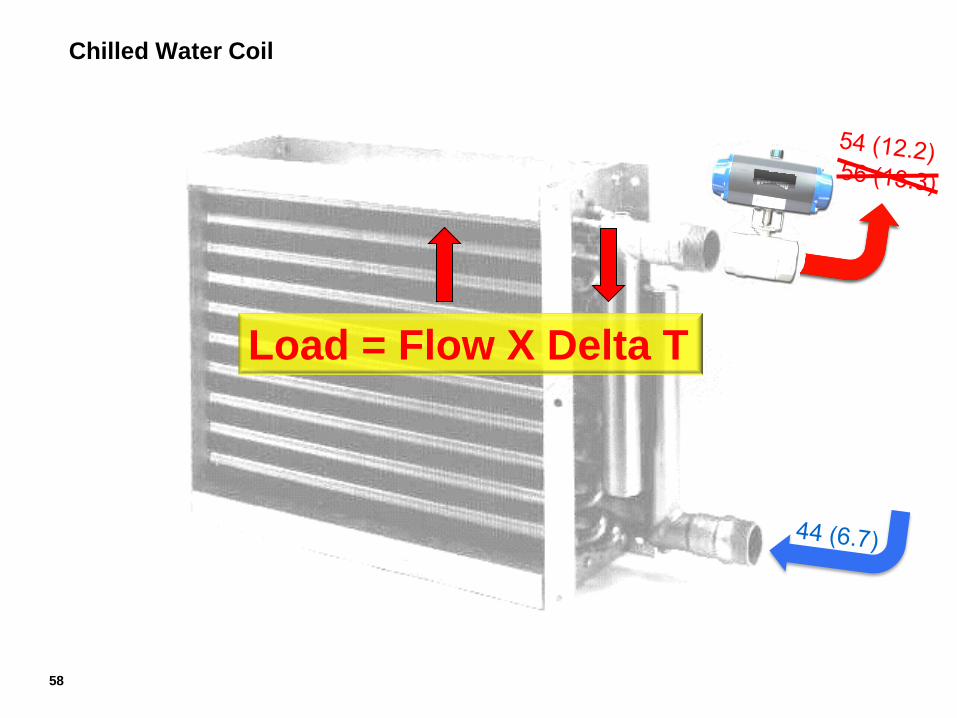
Chilled Water Coil
Load = Flow X Delta T
58
Major Causes of Low Delta T
Dirty Coils
Controls Calibration
Leaky 2-Way Valves
Coils Piped-Up Backwards
59

Chilled Water Coil
60
T
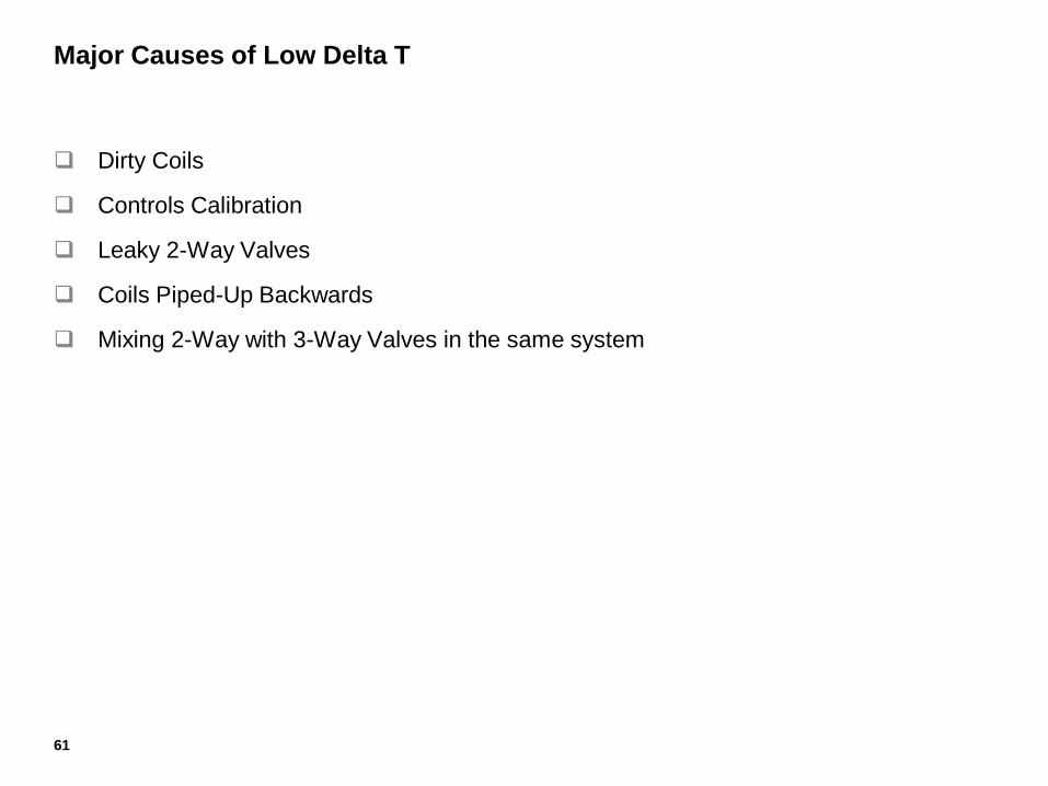
Major Causes of Low Delta T
Dirty Coils
Controls Calibration
Leaky 2-Way Valves
Coils Piped-Up Backwards
Mixing 2-Way with 3-Way Valves in the same system
61
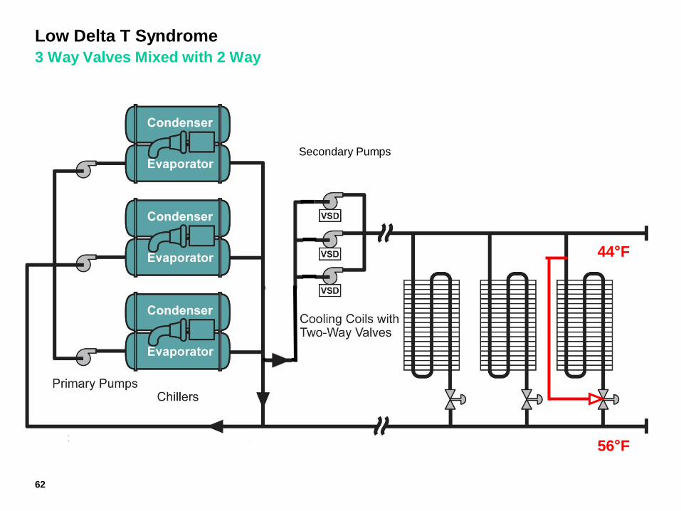
Low Delta T Syndrome
3 Way Valves Mixed with 2 Way
Secondary Pumps
62
44°F
56°F

Primary/Secondary at Design
Ideal Operation
(63 l/s)
(1760 kW)
Secondary Pumps
3000 GPM @ 44 ºF
189 l/s @ 6.7 ºC
56 ºF
(13.3 ºC)
56 ºF
(13.3 ºC)
56 ºF
(13.3 ºC)
56 ºF
(13.3 ºC) (189 l/s) @ 13.3 ºC)
Per Chiller System
Load 500 Tons (1760kW) 1500 Tons (5280kW)
Primary Secondary Bypass
Flow 3000gpm (189 l/s) 3000gpm (189 l/s) 0 gpm (0 l/s)
Delta T 12oF (6.7oC) 12oF (6.7oC) ----
0 GPM @ 44 ºF
0 l/s @ 6.7 ºC
3000 GPM @ 56 ºF
(189 l/s) @ 13.3 ºC)
44.0 °F
(6.7 °C)
63
100% Load = 100% Sec Flow
12ºF
(6.7ºC)
44 ºF
(6.7 ºC)
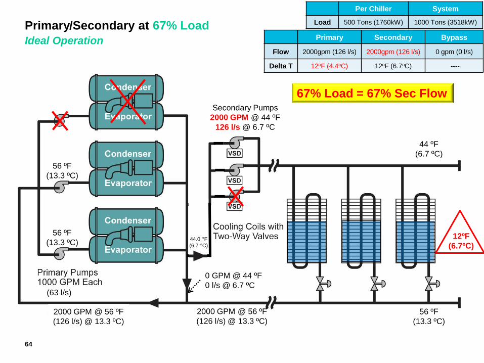
Primary/Secondary at 67% Load
Ideal Operation
(63 l/s)
(1760 kW)
Secondary Pumps
2000 GPM @ 44 ºF
126 l/s @ 6.7 ºC
56 ºF
(13.3 ºC)
56 ºF
(13.3 ºC)
56 ºF
(13.3 ºC) (189 l/s) @ 13.3 ºC)
Per Chiller System
Load 500 Tons (1760kW) 1000 Tons (3518kW)
Primary Secondary Bypass
Flow 2000gpm (126 l/s) 2000gpm (126 l/s) 0 gpm (0 l/s)
Delta T 12oF (4.4oC) 12oF (6.7oC) ----
0 GPM @ 44 ºF
0 l/s @ 6.7 ºC
2000 GPM @ 56 ºF
(126 l/s) @ 13.3 ºC)
44.0 °F
(6.7 °C)
64
67% Load = 67% Sec Flow
2000 GPM @ 56 ºF
(126 l/s) @ 13.3 ºC)
44 ºF
(6.7 ºC)
12ºF
(6.7ºC)

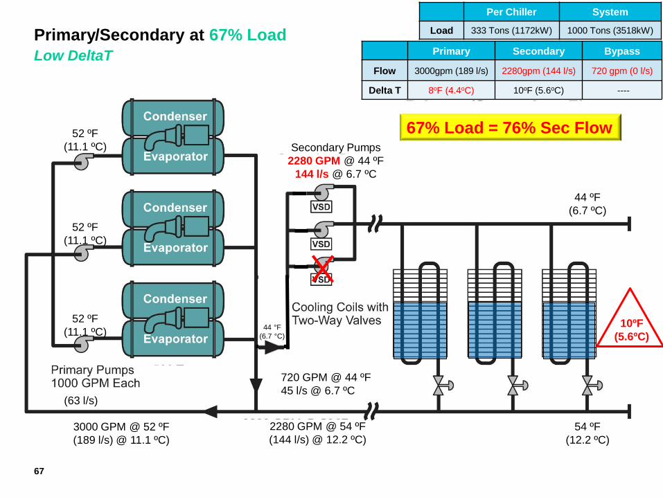
Primary/Secondary at 67% Load
Low DeltaT
(63 l/s)
(1760 kW)
Secondary Pumps
2280 GPM @ 44 ºF
144 l/s @ 6.7 ºC
54 ºF
(12.2 ºC)
54 ºF
(12.2 ºC)
54 ºF
(12.2 ºC) (189 l/s) @ 13.3 ºC)
Per Chiller System
Load 500 Tons (1760kW) 1000 Tons (3518kW)
Primary Secondary Bypass
Flow 2000gpm (126 l/s) 2280gpm (144 l/s) 280 gpm (0 l/s)
Delta T 10oF (5.6oC) 10oF (5.6oC) ----
280 GPM @ 54 ºF
17.7 l/s @ 7.3 ºC
2280 GPM @ 54 ºF
(144 l/s) @ 12.2 ºC)
44 °F
(6.7 °C)
65
67% Load = 76% Sec Flow
2000 GPM @ 54 ºF
(126 l/s) @ 12.2 ºC)
44 ºF
(6.7 ºC)
10ºF
(5.6ºC)
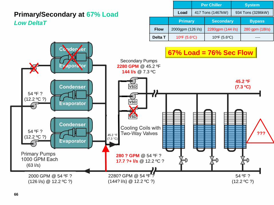
Primary/Secondary at 67% Load
Low DeltaT
(63 l/s)
(1760 kW)
Secondary Pumps
2280 GPM @ 45.2 ºF
144 l/s @ 7.3 ºC
54 ºF ?
(12.2 ºC ?)
54 ºF ?
(12.2 ºC ?)
54 ºF ?
(12.2 ºC ?) (189 l/s) @ 13.3 ºC)
Per Chiller System
Load 417 Tons (1467kW) 934 Tons (3286kW)
Primary Secondary Bypass
Flow 2000gpm (126 l/s) 2280gpm (144 l/s) 280 gpm (18l/s)
Delta T 10oF (5.6oC) 10oF (5.6oC) ----
280 ? GPM @ 54 ºF ?
17.7 ?+ l/s @ 12.2 ºC ?
2280? GPM @ 54 ºF ?
(144? l/s) @ 12.2 ºC ?)
45.2 °F
(7.3 °C)
66
67% Load = 76% Sec Flow
2000 GPM @ 54 ºF ?
(126 l/s) @ 12.2 ºC ?)
45.2 ºF
(7.3 ºC)
???
Primary/Secondary at 67% Load
Low DeltaT
(63 l/s)
(1760 kW)
Secondary Pumps
2280 GPM @ 44 ºF
144 l/s @ 6.7 ºC
52 ºF
(11.1 ºC)
52 ºF
(11.1 ºC)
54 ºF
(12.2 ºC) (189 l/s) @ 13.3 ºC)
Per Chiller System
Load 333 Tons (1172kW) 1000 Tons (3518kW)
Primary Secondary Bypass
Flow 3000gpm (189 l/s) 2280gpm (144 l/s) 720 gpm (0 l/s)
Delta T 8oF (4.4oC) 10oF (5.6oC) ----
720 GPM @ 44 ºF
45 l/s @ 6.7 ºC
2280 GPM @ 54 ºF
(144 l/s) @ 12.2 ºC)
44 °F
(6.7 °C)
67
67% Load = 76% Sec Flow
3000 GPM @ 52 ºF
(189 l/s) @ 11.1 ºC)
44 ºF
(6.7 ºC)
10ºF
(5.6ºC)
52 ºF
(11.1 ºC)
Primary (Constant) / Secondary (Variable)
Rule of Flow
Secondary Pumps
Primary flow must always be equal
to or greater than Secondary flow.
68
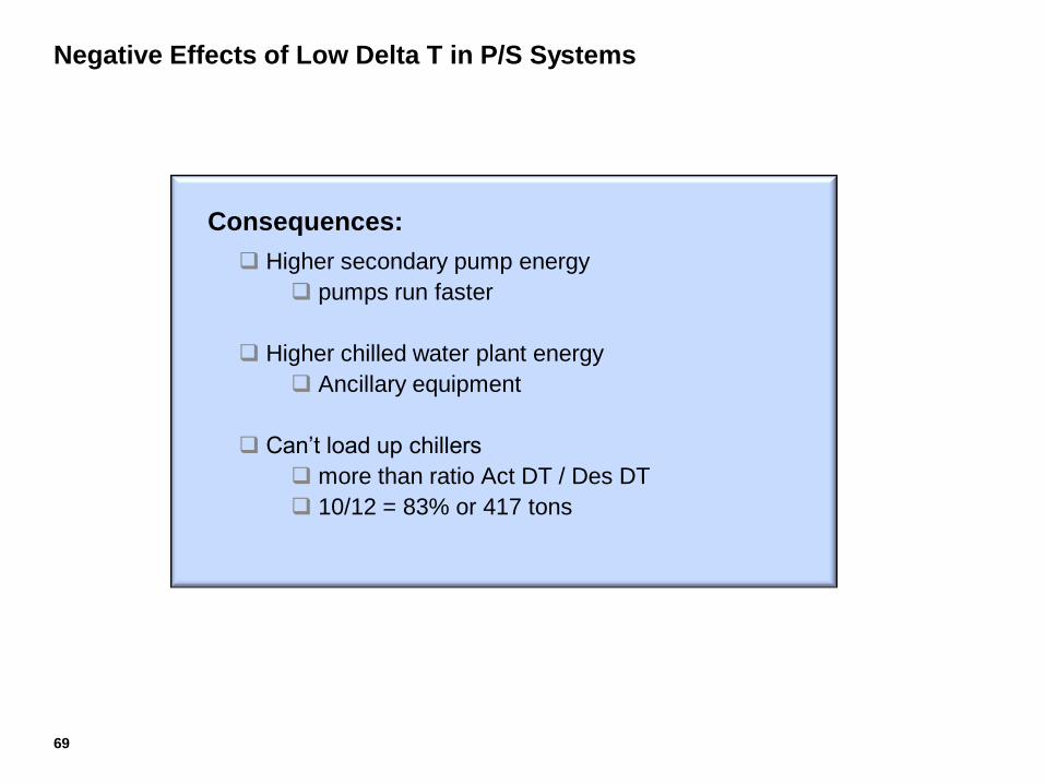
Negative Effects of Low Delta T in P/S Systems
Consequences:
Higher secondary pump energy
pumps run faster
Higher chilled water plant energy
Ancillary equipment
Can’t load up chillers
more than ratio Act DT / Des DT
10/12 = 83% or 417 tons
69
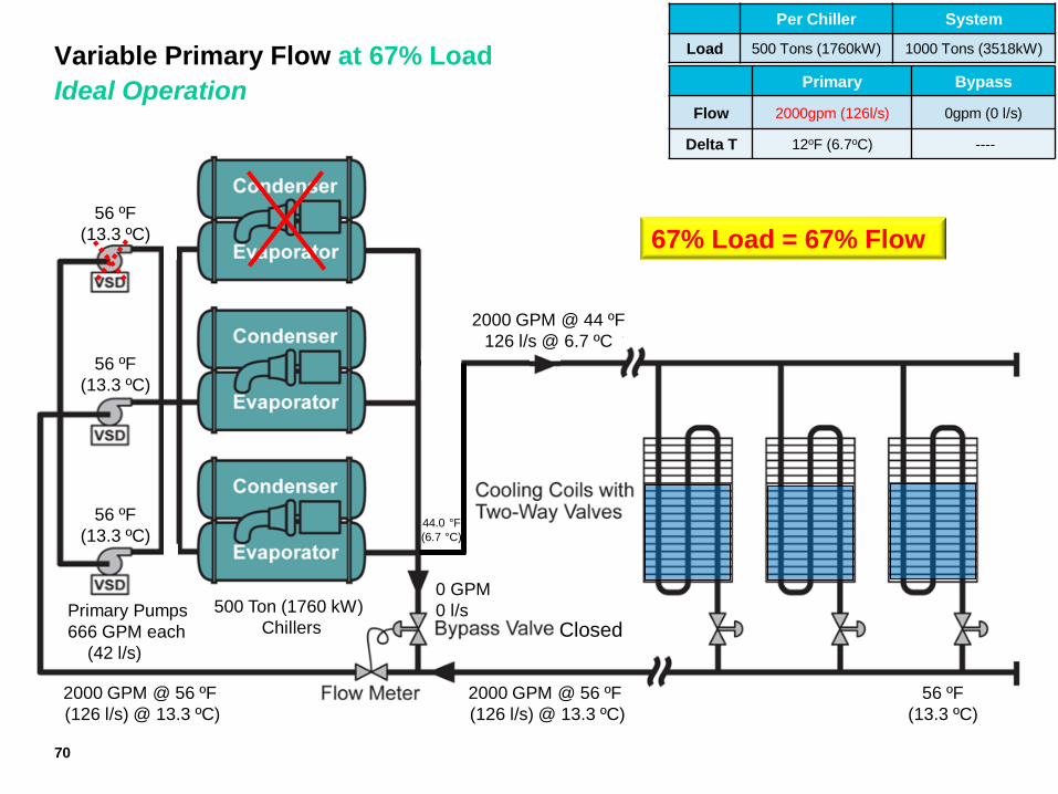
Variable Primary Flow at 67% Load
Ideal Operation
Variable Primary Flow
at 100% System Load Two-way valves control capacity
By varying flow of water in coils
Per Chiller System
Load 500 Tons (1760kW) 1000 Tons (3518kW)
Primary Bypass
Flow 2000gpm (126l/s) 0gpm (0 l/s)
Delta T 12oF (6.7oC) ----
56 ºF
(13.3 ºC)
0 GPM
0 l/s
2000 GPM @ 56 ºF
(126 l/s) @ 13.3 ºC)
44.0 °F
(6.7 °C)
2000 GPM @ 56 ºF
(126 l/s) @ 13.3 ºC)
Primary Pumps
666 GPM each
(42 l/s)
500 Ton (1760 kW)
Chillers
2000 GPM @ 44 ºF
126 l/s @ 6.7 ºC
56 ºF
(13.3 ºC)
56 ºF
(13.3 ºC)
56 ºF
(13.3 ºC)
Closed
70
67% Load = 67% Flow
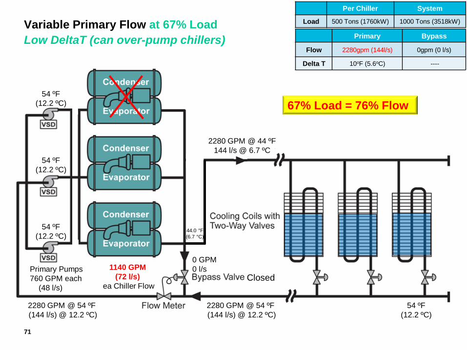
Variable Primary Flow at 67% Load
Low DeltaT (can over-pump chillers)
Variable Primary Flow
at 100% System Load Two-way valves control capacity
By varying flow of water in coils
Per Chiller System
Load 500 Tons (1760kW) 1000 Tons (3518kW)
Primary Bypass
Flow 2280gpm (144l/s) 0gpm (0 l/s)
Delta T 10oF (5.6oC) ----
54 ºF
(12.2 ºC)
0 GPM
0 l/s
2280 GPM @ 54 ºF
(144 l/s) @ 12.2 ºC)
44.0 °F
(6.7 °C)
2280 GPM @ 54 ºF
(144 l/s) @ 12.2 ºC)
Primary Pumps
760 GPM each
(48 l/s)
1140 GPM
(72 l/s)
ea Chiller Flow
2280 GPM @ 44 ºF
144 l/s @ 6.7 ºC
54 ºF
(12.2 ºC)
54 ºF
(12.2 ºC)
54 ºF
(12.2 ºC)
Closed
71
67% Load = 76% Flow
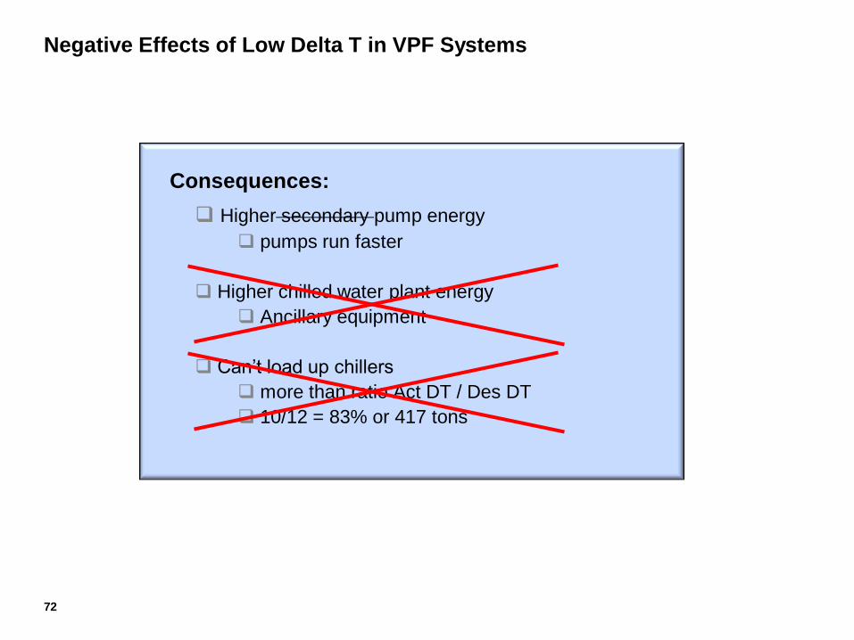
Negative Effects of Low Delta T in VPF Systems
Consequences:
Higher secondary pump energy
pumps run faster
Higher chilled water plant energy
Ancillary equipment
Can’t load up chillers
more than ratio Act DT / Des DT
10/12 = 83% or 417 tons
72
73
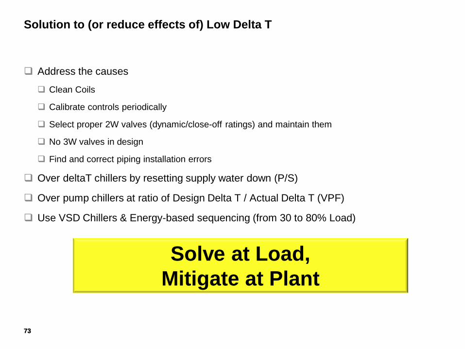
Solution to (or reduce effects of) Low Delta T
Address the causes
Clean Coils
Calibrate controls periodically
Select proper 2W valves (dynamic/close-off ratings) and maintain them
No 3W valves in design
Find and correct piping installation errors
Over deltaT chillers by resetting supply water down (P/S)
Over pump chillers at ratio of Design Delta T / Actual Delta T (VPF)
Use VSD Chillers & Energy-based sequencing (from 30 to 80% Load)
Solve at Load,
Mitigate at Plant
73
Review Chilled Water Piping Configurations
Name the 3 basic piping configurations
Finish Equation: Load = ? X ?
What is the Rule of Flow in P/S configuration?
What are the three negative impacts of Low DeltaT Syndrome
74
75
VPF Systems Design/Control Considerations
Chillers
Equal Sized Chillers preferred, but not required
Maintain Min flow rates with Bypass control (1.5 fps)
Maintain Max flow rates (11.0 to 12.0 fps) and max WPDs (45’ for 2P, 67’ for 3P)
Modulating Isolation Valves (or 2-position stroke-able) set to open in 1.5 to 2 min
Don’t vary flow too quickly through chillers (VSD pump Ramp rate – typical setting of 10%/min)
Sequence
If CSD Chillers – Load-based sequencing…run chillers to max load (Supply Temp rise). Do not
run more chillers than needed (water-cooled, single compressor assumed)
75
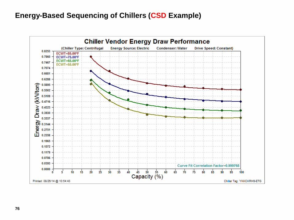
Energy-Based Sequencing of Chillers (CSD Example)
76
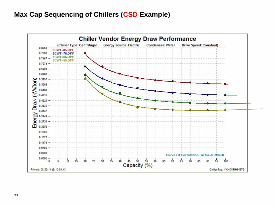
Max Cap Sequencing of Chillers (CSD Example)
77
78
VPF Systems Design/Control Considerations
Chillers
Equal Sized Chillers preferred, but not required
Maintain Min flow rates with Bypass control (1.5 fps)
Maintain Max flow rates (11.0 to 12.0 fps) and max WPDs (45’ for 2P, 67’ for 3P)
Modulating Isolation Valves (or 2-position stroke-able) set to open in 1.5 to 2 min
Don’t vary flow too quickly through chillers (VSD pump Ramp rate – typical setting of 10%/min)
Sequence
If CSD Chillers – Load-based sequencing…run chillers to max load (Supply Temp rise). Do not
run more chillers than needed (water-cooled, single compressor assumed)
If VSD Chillers – Energy-based sequencing…run chillers between 30% and 70% load
(depending on ECWT and actual off-design performance curves). Run more chillers than
load requires.
78
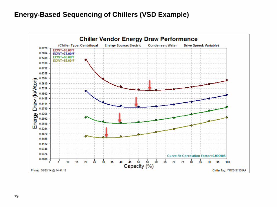
Energy-Based Sequencing of Chillers (VSD Example)
79
80
VPF Systems Design/Control Considerations
Chillers
Equal Sized Chillers preferred, but not required
Maintain Min flow rates with Bypass control (1.5 fps)
Maintain Max flow rates (11.0 to 12.0 fps) and max WPDs (45’ for 2P, 67’ for 3P)
Modulating Isolation Valves (or 2-position stroke-able) set to open in 1.5 to 2 min
Don’t vary flow too quickly through chillers (VSD pump Ramp rate – typical setting of 10%/min)
Sequence
If CSD Chillers – Load-based sequencing…run chillers to max load (Supply Temp rise). Do not
run more chillers than needed (water-cooled, single compressor assumed)
If VSD Chillers – Energy-based sequencing…run chillers between 30% and 80% load
(depending on ECWT and actual off-design performance curves). Run more chillers than load
requires.
Add Chiller - CHW Supply Temp or Load (Flow X Delta T) or amps (if CSD)
Subtract Chiller - Load (Flow X Delta T) or Amps (if CSD)
80
81
VPF Systems Design/Control Considerations
Pumps
Variable Speed Driven
Headered arrangement preferred
Sequence
with chillers (but run an extra pump than # chillers for over-pumping in low delta T situations)
Flow-based sequencing
Energy-based sequencing (most efficient combination of pumps)
Speed controlled by pressure sensors at end of index circuit (fast response important)
Direct wired
Piggyback control for large distances
Optimized - Reset pressure sensor by valve position of coils
81
82
VPF Systems Design/Control Considerations
Bypass Valve
Maintain a minimum chilled water flow rate through the chillers
Differential pressure measurement across each chiller evaporator
Flow meter preferred
Modulates open to maintain the minimum flow through operating chiller(s).
Bypass valve is normally open, but closed unless Min flow breeched
Pipe and valve sized for Min flow of operating chillers
High Range-ability (100:1 or better preferred)
PSID Ratings for Static, Dynamic, And Close Off = Shut Off Head of Pumps
Linear Proportion (Flow to Time) Characteristic preferred
Fast Acting Actuator
Locate in Plant around chillers/pumps (preferred)
Energy
Avoid Network traffic (response time is critical to protect chillers from potential freeze-up)
82
83
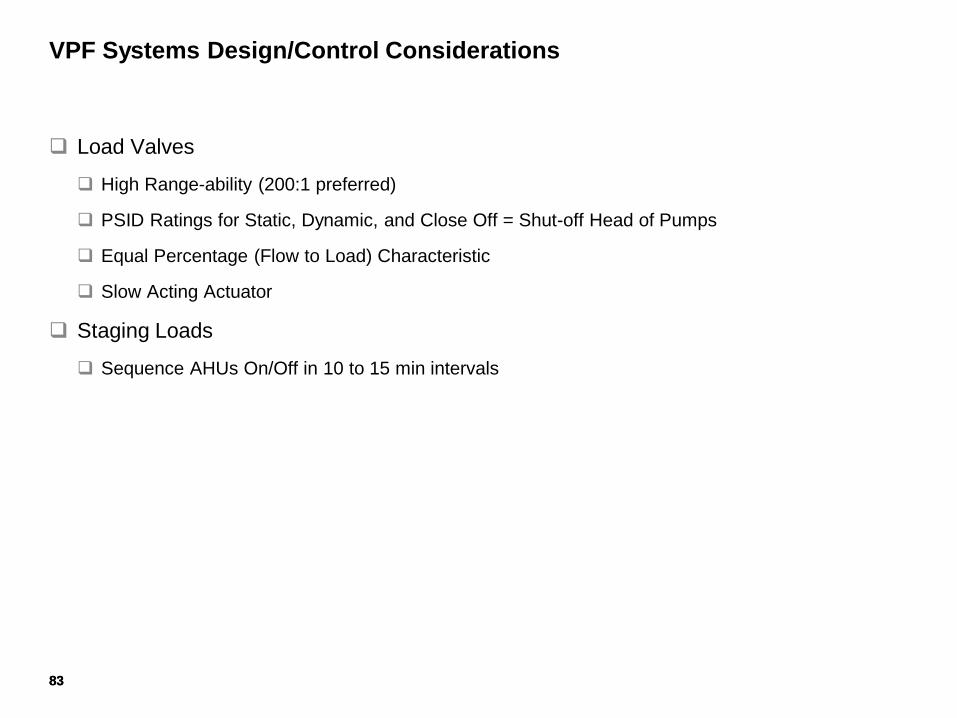
VPF Systems Design/Control Considerations
Load Valves
High Range-ability (200:1 preferred)
PSID Ratings for Static, Dynamic, and Close Off = Shut-off Head of Pumps
Equal Percentage (Flow to Load) Characteristic
Slow Acting Actuator
Staging Loads
Sequence AHUs On/Off in 10 to 15 min intervals
83
84
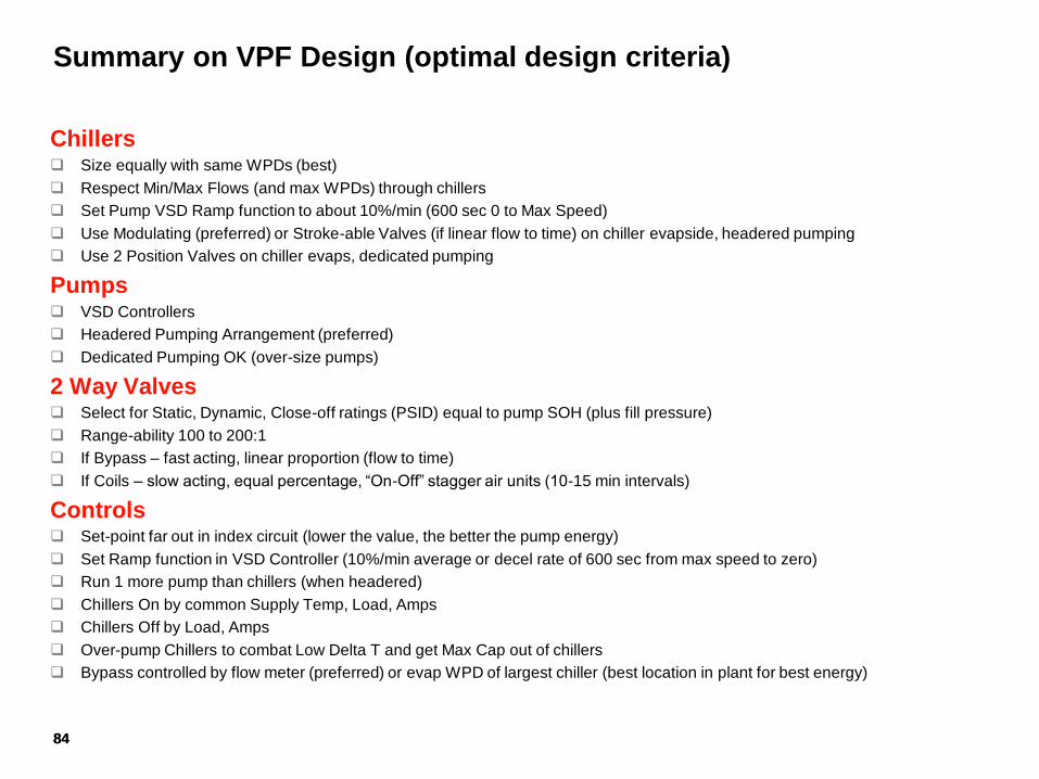
Summary on VPF Design (optimal design criteria)
Chillers Size equally with same WPDs (best)
Respect Min/Max Flows (and max WPDs) through chillers
Set Pump VSD Ramp function to about 10%/min (600 sec 0 to Max Speed)
Use Modulating (preferred) or Stroke-able Valves (if linear flow to time) on chiller evapside, headered pumping
Use 2 Position Valves on chiller evaps, dedicated pumping
Pumps VSD Controllers
Headered Pumping Arrangement (preferred)
Dedicated Pumping OK (over-size pumps)
2 Way Valves Select for Static, Dynamic, Close-off ratings (PSID) equal to pump SOH (plus fill pressure)
Range-ability 100 to 200:1
If Bypass – fast acting, linear proportion (flow to time)
If Coils – slow acting, equal percentage, “On-Off” stagger air units (10-15 min intervals)
Controls Set-point far out in index circuit (lower the value, the better the pump energy)
Set Ramp function in VSD Controller (10%/min average or decel rate of 600 sec from max speed to zero)
Run 1 more pump than chillers (when headered)
Chillers On by common Supply Temp, Load, Amps
Chillers Off by Load, Amps
Over-pump Chillers to combat Low Delta T and get Max Cap out of chillers
Bypass controlled by flow meter (preferred) or evap WPD of largest chiller (best location in plant for best energy)
84
Questions?
Roy Hubbard