Embed Size (px)
Citation preview
19
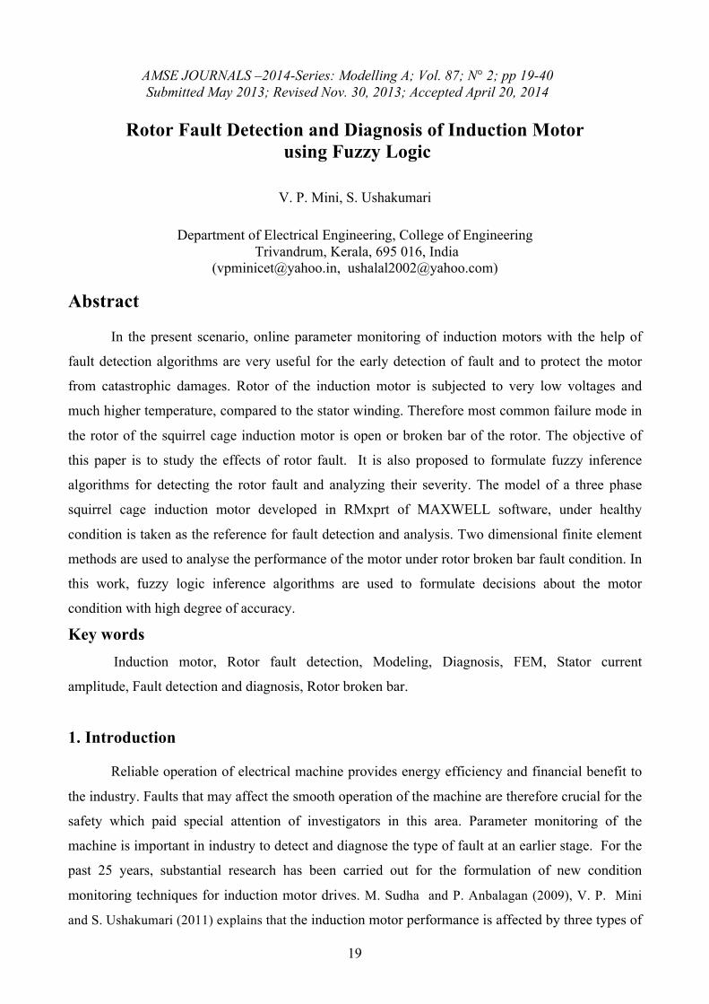
AMSE JOURNALS –2014-Series: Modelling A; Vol. 87; N° 2; pp 19-40 Submitted May 2013; Revised Nov. 30, 2013; Accepted April 20, 2014
Rotor Fault Detection and Diagnosis of Induction Motor
using Fuzzy Logic
V. P. Mini, S. Ushakumari
Department of Electrical Engineering, College of Engineering Trivandrum, Kerala, 695 016, India
([email protected], [email protected])
Abstract
In the present scenario, online parameter monitoring of induction motors with the help of
fault detection algorithms are very useful for the early detection of fault and to protect the motor
from catastrophic damages. Rotor of the induction motor is subjected to very low voltages and
much higher temperature, compared to the stator winding. Therefore most common failure mode in
the rotor of the squirrel cage induction motor is open or broken bar of the rotor. The objective of
this paper is to study the effects of rotor fault. It is also proposed to formulate fuzzy inference
algorithms for detecting the rotor fault and analyzing their severity. The model of a three phase
squirrel cage induction motor developed in RMxprt of MAXWELL software, under healthy
condition is taken as the reference for fault detection and analysis. Two dimensional finite element
methods are used to analyse the performance of the motor under rotor broken bar fault condition. In
this work, fuzzy logic inference algorithms are used to formulate decisions about the motor
condition with high degree of accuracy.
Key words Induction motor, Rotor fault detection, Modeling, Diagnosis, FEM, Stator current
amplitude, Fault detection and diagnosis, Rotor broken bar.
1. Introduction
Reliable operation of electrical machine provides energy efficiency and financial benefit to
the industry. Faults that may affect the smooth operation of the machine are therefore crucial for the
safety which paid special attention of investigators in this area. Parameter monitoring of the
machine is important in industry to detect and diagnose the type of fault at an earlier stage. For the
past 25 years, substantial research has been carried out for the formulation of new condition
monitoring techniques for induction motor drives. M. Sudha and P. Anbalagan (2009), V. P. Mini
and S. Ushakumari (2011) explains that the induction motor performance is affected by three types of
20
faults such as electrical faults, mechanical faults and environmentally related faults. The rotor fault
detection of three phase squirrel cage induction motor by using an on–line observer is given by
Hugo Rodriguez-corties et al. in 2004.
Finite Element analysis of rotor broken bar fault of three phase induction motors is given by A.
Bentounsi and A. Nicolas (1998). This paper discusses the torque developed in the machine is
reduced due to the rotor broken bar fault. With the help of spectral analysis, they had proved that
when a rotor bar is broken, normal flux density in the teeth located in front of the defective bar is
increased and that of the other side is decreased. A. Bentounsi and A. Nicolas in 1998 proposed a
local approach to tackle the problem of breaking bars and end-rings of squirrel cage in induction
machines mainly based on the signature of the local variable, like normal flux density. The Vienna
Monitoring Method for detection of rotor bar fault of a three phase squirrel cage induction motor is
given by Christian Kral and Rudolf S, et al. in 2000. The Vienna Monitoring Method compares
online voltage model output with a current model and observed the deviations in a rotor fixed
reference frame. Szabó Loránd and Dobai Jenő Barna et al., in 2004 explained the current
signature analysis for rotor broken bar fault of three phase squirrel cage induction motor. As per
this paper, decibel (dB) versus frequency spectrum is used as the current signature pattern to
detect the rotor broken bar fault. The Extended Park’s Vector Approach (EPVA) for broken rotor
bar fault detection of a three phase squirrel cage induction motor is given by Zexiang Ca and Aiyun
Gao et al., in 2004. Motor Current Signature analysis for rotor fault of an induction motor is given
by Carlo Concerti and Giovanni Franceschini in 2008. The features of stator currents and of radial
and axial core vibration signals used for the detection and stray flux signals are taken into account
to increase the reliability of the diagnostic system. The Artificial Neural Network (ANN) algorithm
for broken bar fault detection of three phase squirrel cage induction motor is given by Hayri Arabaci
and Osman Bilgin in 2009. According to EPVA, the spectrum of steady stator Current Park’s
vector module consists of double frequency components.
This paper proposes a fuzzy logic algorithm for detection and diagnosis of rotor broken bar
fault of a three phase squirrel cage induction motor, based on the amplitude of stator currents,
speed, negative sequence current and peak magnitude of FFT of line currents. It is a realistic and
straight forward method to simulate rotor broken bar faults of a three phase squirrel cage induction
motor. One fuzzy logic algorithm is proposed for identifying the rotor broken bar fault and
analyzing its severity. The detection and analysis of rotor broken bar fault, carried out in this paper
is divided into three sections. The first section consists of the complete design of three phase
squirrel cage induction motor and develops a machine based on designed values using Rmxprt of
the Maxwell Software. The Maxwell 2D analysis of normal machine is included in the second part.
The introduction of partial and complete rotor broken bar faults into the healthy machine and the
21
detection and analysis of such fault conditions using fuzzy logic algorithm is discussed in the last
section.
2. Causes and effects of rotor faults
The classification of squirrel cage induction motors based on rotor construction is given by
Subhasis Nandi and Hamid A. Toliyet in 1999 and V. P. Mini and S. Ushakumari in 2012. In this
paper, squirrel cage induction motors are classified into two groups such as cast rotors and
fabricated rotors. Cast rotors are commonly used in small machines and fabricated rotors are used in
large machines and special applications. The rotor of a squirrel cage induction motor is a cylindrical
cage, comprised of axial bars terminated in annular rings. Cast Aluminum is used for the bars and
the end rings. The conductors are generally skewed along the rotor length to reduce the noise and
torque fluctuations. The thin laminations reduce eddy current losses. The manufacturing defects
such as weak joints at the bar ends, internal constraints (electromagnetic and thermal) and external
constraints (overload and frequent start-ups) due to wear phenomenon are the main causes of rotor
fault in a three phase squirrel cage induction motor. The other reasons for the rotor fault of an
induction motor are thermal stresses produced due to thermal overload and unbalance, mechanical
stresses produced due to lose laminations and bearing failure, magnetic stresses caused by
electromagnetic forces and electromagnetic noise, dynamic stresses arising from shaft torque and
centrifugal forces and residual stresses due to manufacturing problem and vibration etc. The rotor is
subjected to much lower voltages and much higher temperature compared to the stator windings.
Therefore, the most common failure mode in rotors is open or broken rotor bar. Rotor faults are
very important because, their symptoms are sensed by usual measurement systems and it will affect
the motor movement characteristics. The effects of the rotor fault of an induction motor are
fluctuation and reduction in speed and torque, temperature rise due to increase in stator current and
harmonic losses.
3. Rotor Fault Detection Methods This section presents different types of fault detection method that had been proposed to
identify the rotor faults of a three phase squirrel cage induction motor. The most frequently used
detection methods are Motor Current Signature Analysis (MCSA), Acoustic noise measurement
techniques, Artificial Intelligence and Neural network based techniques, Noise and Vibration
monitoring techniques, Electromagnetic field monitoring technique using search coils, or coils
wound around motor shafts (axial flux related detection), Temperature measurement techniques,
Infrared recognition technique, Radio Frequency (RF) emissions monitoring techniques and
Chemical analysis, etc.
Online monitoring scheme to detect the rotor broken bar fault of a drive system is given by
Hugo Rodriguez-Cortes et al. in 2004, based on the spectrum analysis of stator current. The
22
requirement of mathematical model of the machine is one of the drawbacks of this technique. Jarmo
Lehtonen et al. (2005) explained the fault diagnosis of induction motor with dynamic neural
network. In dynamic neural network technique, neural network time-series models are created for
the normal and faulty motor and a Bayesian classifier is used to determine the correct classification
of the motor condition. The motor current signature analysis of rotor fault detection for a three
phase squirrel cage induction motor is given by Aderiano M. Da Silva and Richard J. Povinelli et.al
in 2006. This method is based on the analysis of three phase stator current envelopes of induction
machines using reconstructed phase space transforms. In their paper, signatures of each type of fault
from the corresponding three phase current envelope are created. Rotor fault detection analysis of
an induction motor using vibration monitoring is given by Carlo Concari, et.al. in 2008. Vibrations
produced in the core due to inter bar currents of faulty rotor are sensed with the help vibration
sensor. This diagnostic system investigates the axial core vibration signals, stator currents and stray
flux signals for fault identification.
In almost all of the above methods, the fault detection and analysis of three phase squirrel
cage induction motor is performed with the help of mathematical model. The mathematical model
of squirrel cage induction motor with rotor broken bar fault is very complex due to the large
number of differential equations. The aim of this paper is to detect the effect of partially and
completely rotor broken bar fault of a three phase squirrel cage induction motor using Finite
Element Method and also to propose a fuzzy logic algorithm for identification and analysis of rotor
broken bar fault.
4. Finite Element Method (FEM)
The fault of three phase squirrel cage induction machines can be studied through the
physical experiment and computer simulation. The computer simulation is more economical and
flexible. Without hardware prototyping, it is easy to change parameters to run the machine at
different conditions. The most important part of the computer simulation of rotor fault analysis of
induction motor is the modeling of the machine. The induction machine can be modeled using
analytical approach or time step finite element method (FEM). Analytical approach is a circuit
oriented approach and use linearized parameters for representing the magnetic property of the
machine. The time step FEM is more accurate than the analytical approach because it is based on
the machine geometry. So the finite element model of an induction motor is suitable for the analysis
of rotor fault condition because it studies the behavior of electromagnetic field inside the machine
directly based on its geometry and material properties.
Finite Element Method (FEM) is a numerical method for solving a differential or integral
equation. It is applied to a number of physical problems, where the governing differential equations
23
are available. The finite element method consists of piecewise continuous function for the solution
so that error in the solution is reduced. The performance evaluation of three phase squirrel cage
induction machine based on finite element method is given by Ali Ebadi, Mohammad Mirzaie et al.
in 2011. Rotor fault analysis of three phase squirrel cage induction machine using FEM is given by
Mini.V. P. and S. Ushakumari in 2012. This powerful design tool has significantly improved both,
the standard of engineering designs and the methodology of the design process in many industrial
applications. Some benefits of FEM are increased accuracy, enhanced design and better insight into
critical design parameters, virtual prototyping, fewer hardware prototypes, a faster and less
expensive design cycle, increased productivity and increased revenue. Basic theory of conventional
FEM and direct FEM is given by P Lombard et al. in 1992 . Eddy currents, external sources and
impedances are the main parameters that depend on the machine performance. In conventional
FEM, the differential equations that govern the machine performance is converted into the field
variables for analysis. When using conventional FEM, it is difficult to obtain the machine
performance taking into account the eddy current, external sources and impedances. In order to
overcome this difficulty, direct FEM is used in which, magnetic field circuit is directly coupled to
electrical circuit for analysis. So all variables are assumed to vary sinusoidal with time and also two
dimensional domains are considered for the analysis. Here, the formulation is implemented in
Maxwell 2D software. Maxwell includes 3-D/2-D magnetic transient, AC electromagnetic,
magneto static, electrostatic, DC conduction and electric transient solvers that accurately solve for
field parameters including force, torque, capacitance, inductance, resistance and impedance.
5. Design of Three Phase Induction Motor
Design of an electric machine is the physical realization of the theoretical concept of the
electrical machine to perform the specified task with economy and efficiency. The output equation
in terms of fundamental values is converted into the output equation in terms of machine
dimensions is the first step of the machine design. The size and shape of the machine depends on
its rating. The detailed design of a 3.7 kW, 400 V, 3 phase, and 50 Hz squirrel cage induction motor
is given by V. P. Mini and S. Ushakumari (2012). The design of three phase squirrel cage induction
motor consists of three parts. The first part consists of the design of main dimensions, the stator and
rotor design are included in the second and third part respectively.
5. a. Design of Main Dimension The stator core diameter of the induction motor ‘D’ and stator core length ‘L’ of an
induction motor are known as the main dimensions of a three phase induction machine. The
starting point in the design of rotating electrical machines is the selection of specific magnetic
24
loading and specific electric loading. Total flux around the stator periphery at the air gap is called
total magnetic loading (Pφ). The total number of ampere conductors around the armature periphery
is called total electric loading ( IzZ). The specific magnetic loading is the average flux density (B avg) over the air gap of the
machine and the specific electric loading (ac) is the number of stator ampere conductors per meter
of stator periphery at the air gap. The factors considered for the selection of average flux density are
power factor, iron loss and over load capacity. The value of flux density in the air gap should be
small, otherwise the machine will draw a large magnetizing current and the power factor is very
low. The increased value of gap density results in increased iron loss and decreased efficiency. For
a large value of air gap flux density, the flux per pole is large and the leakage reactance becomes
small. With small leakage reactance, the machine has large over load capacity. Most of the
induction machines have an over load capacity of twice the horse power but the speed is reduced.
There is a trade-off between the two, for a 50 Hz machine of normal design, the value of Bavg lies
between 0.3 and 0.6 wb/m 2 and the specific electric loading (ac) value corresponding to Bavg (0.45
wb/m2) is 26000. The value of efficiency and power factor of an induction machine for a 50 Hz machine is
selected from the table. Efficiency η = 0.83 and power factor pf = 0.84. The kVA rating of an
induction machine in terms of fundamental values and machine dimensions are expressed in eqn (1)
and eqn (2). That is,
pfkWQ×
=η
(1)
LnsDQ 20C = (2)
Where C0 is the output coefficient
3avg0 10B 11 −×= wacKC (3)
snCQLD0
2 = (4)
The product LD2 is obtained from (4). The ratio of core length (L) to pole pitch (τ) is
used for the separation of stator core diameter and stator core length of an induction machine. For
economic and good efficiency induction machine, the ratio of (L/τ) is taken as 1.5. The values of
stator core length (L) and stator core diameter (D) is obtained as ;
0.09263 , m 0.139 L , m 0.118 D === τ
The core length of the designed machine is higher than 100 mm and therefore ventilating ducts
are provided. The width of each duct is 10 mm. So the Net iron length of the machine,
25
( )0.01 - L 0.9 =iL 0.1161m = (5) 5. b. Stator Design
Important points included in the stator design are the determination of stator turns per phase,
stator conductors per slot, stator slot dimension and stator core dimension and conductor size.
The stator turns per phase
325 f 4.44
E m
s ==w
s kT
φ (6)
Semi enclosed slots are used for small machines. For a 4 pole 36 slots machine, stator conductors per slot is 54 6 ==
s
sss S
TZ (7)
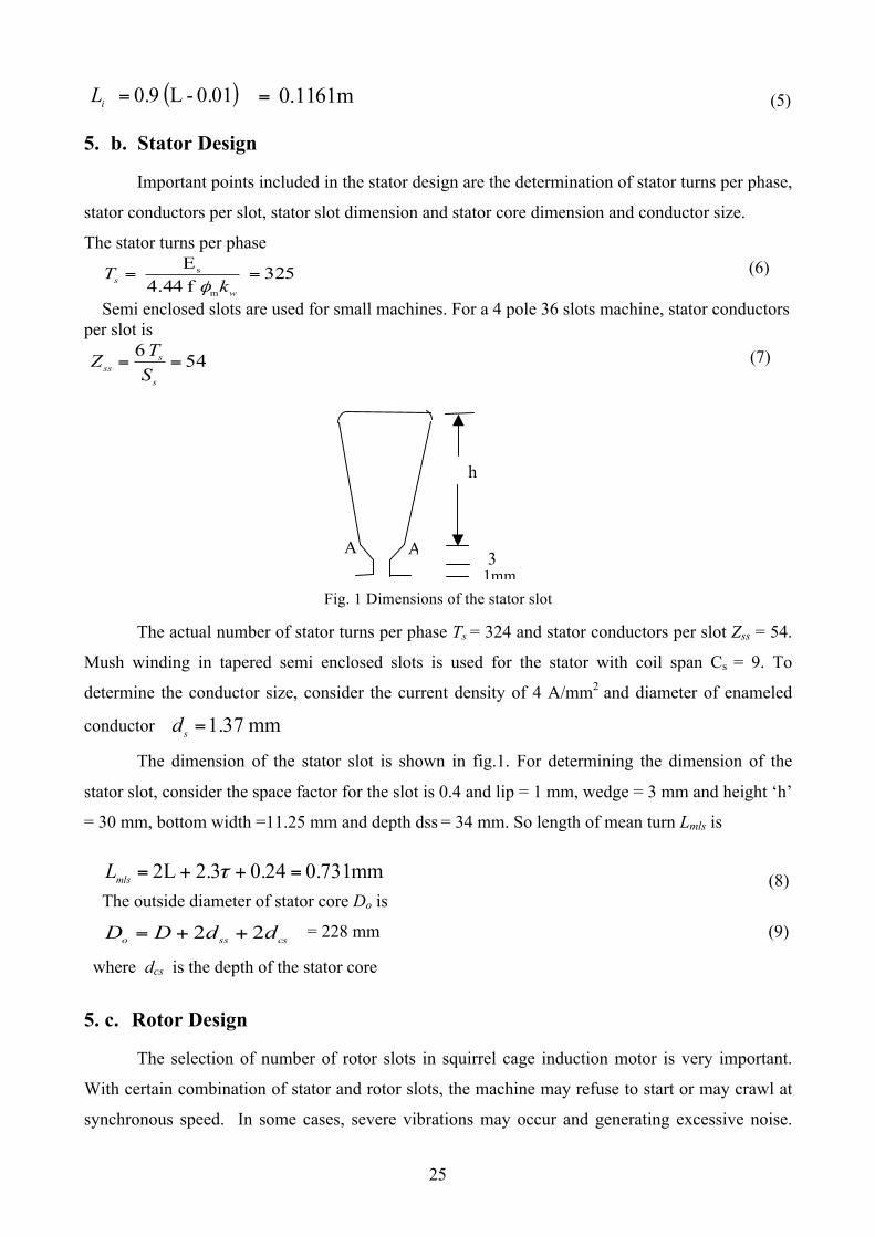
Fig. 1 Dimensions of the stator slot
The actual number of stator turns per phase Ts = 324 and stator conductors per slot Zss = 54.
Mush winding in tapered semi enclosed slots is used for the stator with coil span Cs = 9. To
determine the conductor size, consider the current density of 4 A/mm2 and diameter of enameled
conductor mm 1.37 =sd
The dimension of the stator slot is shown in fig.1. For determining the dimension of the
stator slot, consider the space factor for the slot is 0.4 and lip = 1 mm, wedge = 3 mm and height ‘h’
= 30 mm, bottom width =11.25 mm and depth dss = 34 mm. So length of mean turn Lmls is
0.731mm 0.24 2.3 2L =++= τmlsL (8)
The outside diameter of stator core Do is
cssso ddDD 22 ++= = 228 mm (9)
where dcs is the depth of the stator core
5. c. Rotor Design
The selection of number of rotor slots in squirrel cage induction motor is very important.
With certain combination of stator and rotor slots, the machine may refuse to start or may crawl at
synchronous speed. In some cases, severe vibrations may occur and generating excessive noise.
h mm
3mm 1mm
A A
26
These effects are produced by harmonic fields. The harmonic fields are responsible for increase in
stray load losses and increased motor heating.
As per rules for selecting the number of rotor slots of a three phase induction motor [20],
the number of rotor slots Sr is 26 ;
The rotor diameter
mm 117.2 2 =−= gr lDD (10)
Where lg is the length of air gap and it is 0.4 mm The rotor slot and bar dimensions of the three
phase squirrel cage induction motor depends upon the rotor bar current Ib.
φcos 2 sr
swsb I
STkmI = (11)
where ‘ms’ is the number of stator phases, ‘kw’ is the winding factor and ‘Ts’ is turns per phase in the
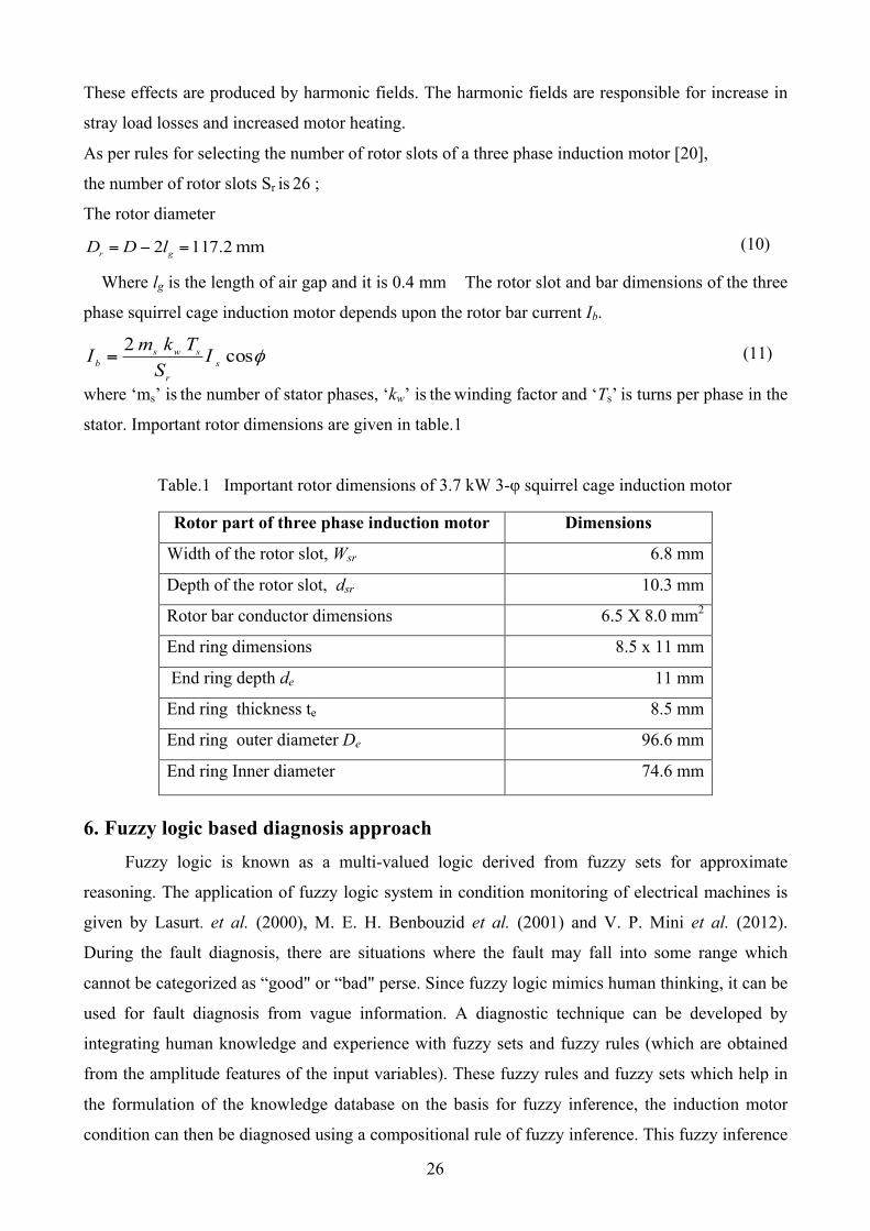
stator. Important rotor dimensions are given in table.1
Table.1 Important rotor dimensions of 3.7 kW 3-φ squirrel cage induction motor
Rotor part of three phase induction motor Dimensions
Width of the rotor slot, Wsr 6.8 mm
Depth of the rotor slot, dsr 10.3 mm
Rotor bar conductor dimensions 6.5 X 8.0 mm2
End ring dimensions 8.5 x 11 mm
End ring depth de 11 mm
End ring thickness te 8.5 mm
End ring outer diameter De 96.6 mm
End ring Inner diameter 74.6 mm
6. Fuzzy logic based diagnosis approach
Fuzzy logic is known as a multi-valued logic derived from fuzzy sets for approximate
reasoning. The application of fuzzy logic system in condition monitoring of electrical machines is
given by Lasurt. et al. (2000), M. E. H. Benbouzid et al. (2001) and V. P. Mini et al. (2012).
During the fault diagnosis, there are situations where the fault may fall into some range which
cannot be categorized as “good" or “bad" perse. Since fuzzy logic mimics human thinking, it can be
used for fault diagnosis from vague information. A diagnostic technique can be developed by
integrating human knowledge and experience with fuzzy sets and fuzzy rules (which are obtained
from the amplitude features of the input variables). These fuzzy rules and fuzzy sets which help in
the formulation of the knowledge database on the basis for fuzzy inference, the induction motor
condition can then be diagnosed using a compositional rule of fuzzy inference. This fuzzy inference
27
system comprises the fuzzy system input variables, output variables and linguistic variables. A
summary is given in the following sections.
6. a. Fuzzy system input-output variables
The stator currents, negative sequence current, speed and FFT of the stator currents are taken
as the input variables for condition monitoring algorithm. The induction motor condition can be
deduced by observing the amplitude of stator currents, negative sequence current, speed and
magnitude of FFT of the stator currents of the machine under different fault conditions.
Interpretation of results, directly from the input variables is very difficult, because the input
amplitudes are vague. Therefore, fuzzy logic is used to represent numerical data as linguistic
information. In this work, the fuzzy logic algorithm is used for rotor broken bar fault detection and
for analysing the severity of fault. For this case, six variables such as each phase RMS amplitude of
stator current Ia, Ib and Ic , amplitude of negative sequence current Ineg, amplitude of speed and
magnitude of FFT of the stator currents are used as the input variables. The motor condition, ‘MC’,
is chosen as the output variable. All the system inputs and outputs are defined using fuzzy set
theory.
6. b. Linguistic Variables
It is known that basic tools of fuzzy logic are linguistic variables. Their values are words or
sentences in a natural or artificial language, providing a meaningful systematic manipulation of
vague and imprecise concepts. For rotor broken bar fault analysis, the output is the term set T(MC),
interpreting motor condition, ‘MC’, as a linguistic variable, could be T(MC ) = {Normal (NR) ,
Slightly faulty (SLF), Medium faulty (MF) ,Seriously Faulty (SEF)}. The input variables, Ia, Ib, and
Ic are interpreted as linguistic variables, with term set T(Q) = {Very Very Low(VVL), Very Low
(VL), Low (L), Medium(M), High(H),Very High (VH), Very Very High (VVH)}, the negative
sequence current amplitude Ineg is interpreted as linguistic variables with term set T(Ineg) = {Very
Very Very Small (VVVS), Very Very Small (VVS), Very Small (VS), Small (S), Medium (M),
Large(L), Very Large (VL), Very Very Large (VVL)}, Speed amplitude N is interpreted as linguistic
variables, with term set T(N)= {Very Very Very Small (VVVS), Very Very Small (VVS), Very Small
(VS), Small (S), Medium (M), Large (L), Very Large (VL) Very Very Large (VVL), Very Very Very
Large(VVVL)} and magnitude of FFT is interpreted as linguistic variable with term set T(/FFT/ )=
{Small Small Small (SSS), Small Small(SS), Small(S), medium(M), Large(L), Large Large
(LL),Large Large Large(LLL)}
where Q = Ia, Ib, Ic respectively.
6.c. Fuzzy membership functions
28
In order to handle the fuzzy data, it is necessary to convert the actual data into the fuzzy data
based on certain membership functions. In this work, trapezoidal functions are used as the
membership functions.
Table 2. Fuzzy output membership function value ranges and corresponding motor condition for
rotor broken bar faults
Output membership value range Motor condition
0.0 – 3.0 Normal (NR)
2.5 – 5.5 Slightly Faulty (SLF)
5.0 – 8.0 Medium Faulty (MF)
7.5-10.5 Seriously Faulty (SEF)
Fuzzy rules and membership functions are constructed by observing the data set. For the
measurements related to the stator currents, more insight into the data is needed, so membership
functions will be generated for all input and output variables. According to the severity of the fault,
fault condition is divided into four fuzzy sets. The output fuzzy linguistic variables and their
membership function value ranges for rotor broken bar fault are given in table 2. For detection and
diagnosis of faults, the stator currents, negative sequence component of stator current, speed and
magnitude of FFT are converted into corresponding fuzzy value as inputs. The outputs are then
evaluated by fuzzy logic inference engine using the knowledge base.
7.0 Development of 3-ϕ IM Using RMxprt
A fuzzy logic algorithm is developed for the detection and diagnosis of the rotor broken
bar fault of a three phase squirrel cage induction motor. In this work, a 3.7 kW, 400 V, 3 phase, 4
pole, 50 Hz; squirrel cage induction motor is used for the simulation. The three phase squirrel cage
induction machine used for simulation is developed in RMxprt of Maxwell software using design
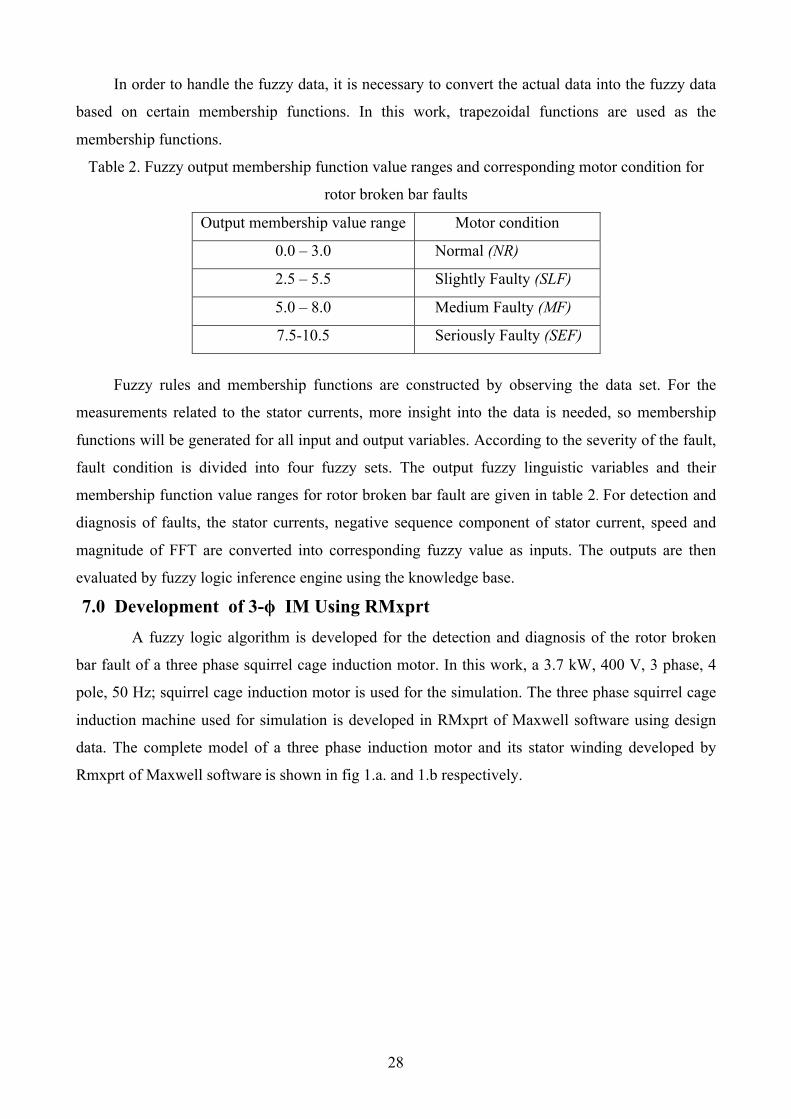
data. The complete model of a three phase induction motor and its stator winding developed by
Rmxprt of Maxwell software is shown in fig 1.a. and 1.b respectively.
29
a. b.
Fig. 1 a. Complete model of three phase squirrel cage induction motor. b. stator winding
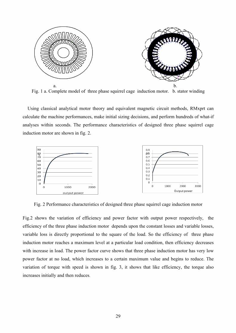
Using classical analytical motor theory and equivalent magnetic circuit methods, RMxprt can
calculate the machine performances, make initial sizing decisions, and perform hundreds of what-if
analyses within seconds. The performance characteristics of designed three phase squirrel cage
induction motor are shown in fig. 2.
Fig. 2 Performance characteristics of designed three phase squirrel cage induction motor
Fig.2 shows the variation of efficiency and power factor with output power respectively, the
efficiency of the three phase induction motor depends upon the constant losses and variable losses,
variable loss is directly proportional to the square of the load. So the efficiency of three phase
induction motor reaches a maximum level at a particular load condition, then efficiency decreases
with increase in load. The power factor curve shows that three phase induction motor has very low
power factor at no load, which increases to a certain maximum value and begins to reduce. The
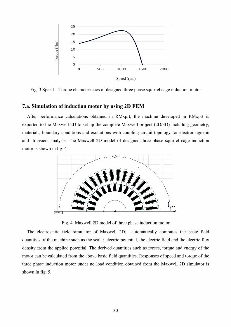
variation of torque with speed is shown in fig. 3, it shows that like efficiency, the torque also
increases initially and then reduces.
30
Fig. 3 Speed – Torque characteristics of designed three phase squirrel cage induction motor
7.a. Simulation of induction motor by using 2D FEM
After performance calculations obtained in RMxprt, the machine developed in RMxprt is
exported to the Maxwell 2D to set up the complete Maxwell project (2D/3D) including geometry,
materials, boundary conditions and excitations with coupling circuit topology for electromagnetic
and transient analysis. The Maxwell 2D model of designed three phase squirrel cage induction
motor is shown in fig. 4
Fig. 4 Maxwell 2D model of three phase induction motor
The electrostatic field simulator of Maxwell 2D, automatically computes the basic field
quantities of the machine such as the scalar electric potential, the electric field and the electric flux
density from the applied potential. The derived quantities such as forces, torque and energy of the
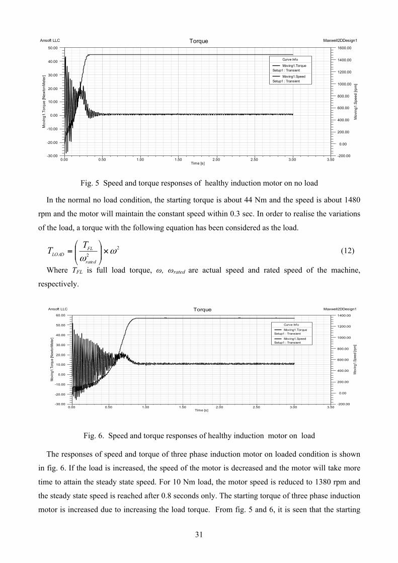
motor can be calculated from the above basic field quantities. Responses of speed and torque of the
three phase induction motor under no load condition obtained from the Maxwell 2D simulator is
shown in fig. 5.
Speed (rpm)
Torq
ue (N
m)
31
0.00 0.50 1.00 1.50 2.00 2.50 3.00 3.50Time [s]
-30.00
-20.00
-10.00
0.00
10.00
20.00
30.00
40.00
50.00M
ovin
g1.T
orqu
e [N
ewto
nMet
er]
-200.00
0.00
200.00
400.00
600.00
800.00
1000.00
1200.00
1400.00
1600.00
Mov
ing1
.Spe
ed [r
pm]
Ansoft LLC Maxwell2DDesign1Torque
Curve Info
Moving1.TorqueSetup1 : Transient
Moving1.SpeedSetup1 : Transient
Fig. 5 Speed and torque responses of healthy induction motor on no load
In the normal no load condition, the starting torque is about 44 Nm and the speed is about 1480
rpm and the motor will maintain the constant speed within 0.3 sec. In order to realise the variations
of the load, a torque with the following equation has been considered as the load.
22
ωω
×⎟⎟⎠
⎞⎜⎜⎝
⎛=
rated
FLLOAD
TT (12)
Where TFL is full load torque, ω, ωrated are actual speed and rated speed of the machine,
respectively.
0.00 0.50 1.00 1.50 2.00 2.50 3.00 3.50Time [s]
-30.00
-20.00
-10.00
0.00
10.00
20.00
30.00
40.00
50.00
60.00
Mov
ing1
.Tor
que
[New
tonM
eter
]
-200.00
0.00
200.00
400.00
600.00
800.00
1000.00
1200.00
1400.00
Mov
ing1
.Spe
ed [r
pm]
Ansoft LLC Maxwell2DDesign1Torque
Curve Info
Moving1.TorqueSetup1 : Transient
Moving1.SpeedSetup1 : Transient
Fig. 6. Speed and torque responses of healthy induction motor on load
The responses of speed and torque of three phase induction motor on loaded condition is shown
in fig. 6. If the load is increased, the speed of the motor is decreased and the motor will take more
time to attain the steady state speed. For 10 Nm load, the motor speed is reduced to 1380 rpm and
the steady state speed is reached after 0.8 seconds only. The starting torque of three phase induction
motor is increased due to increasing the load torque. From fig. 5 and 6, it is seen that the starting
32
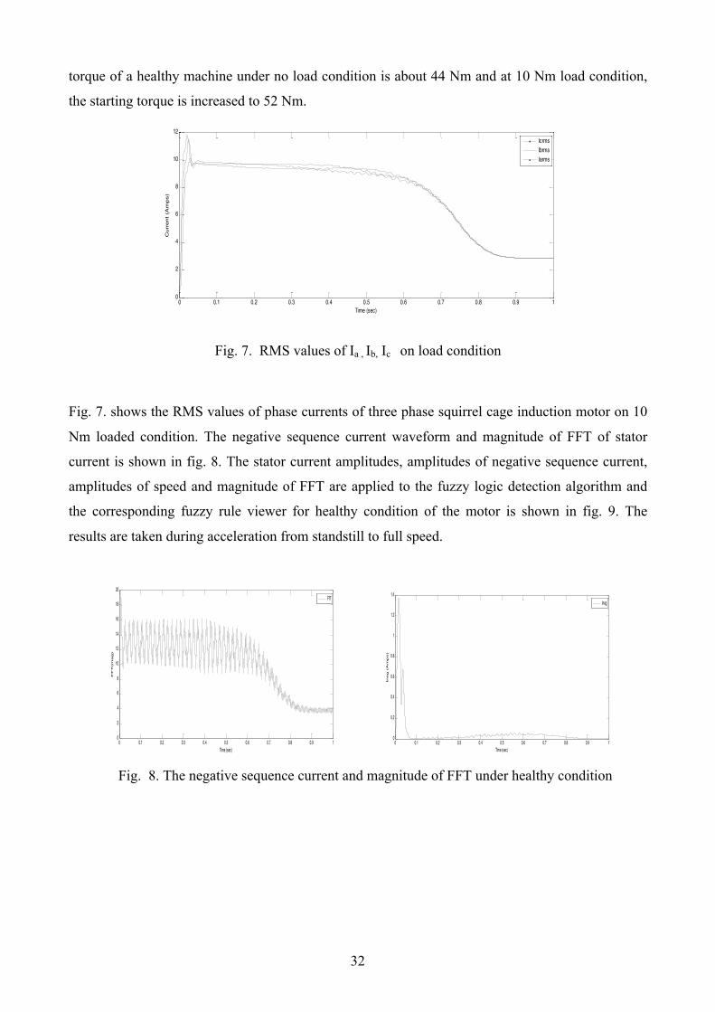
torque of a healthy machine under no load condition is about 44 Nm and at 10 Nm load condition,
the starting torque is increased to 52 Nm.
0 0.1 0.2 0.3 0.4 0.5 0.6 0.7 0.8 0.9 10
2
4
6
8
10
12
Time (sec)
Curr
ent
(Am
ps)
IcrmsIbrmsIarms
Fig. 7. RMS values of Ia , Ib, Ic on load condition
Fig. 7. shows the RMS values of phase currents of three phase squirrel cage induction motor on 10
Nm loaded condition. The negative sequence current waveform and magnitude of FFT of stator
current is shown in fig. 8. The stator current amplitudes, amplitudes of negative sequence current,
amplitudes of speed and magnitude of FFT are applied to the fuzzy logic detection algorithm and
the corresponding fuzzy rule viewer for healthy condition of the motor is shown in fig. 9. The
results are taken during acceleration from standstill to full speed.
0 0.1 0.2 0.3 0.4 0.5 0.6 0.7 0.8 0.9 10
2
4
6
8
10
12
14
16
18
20
Time (sec)
FF
T(m
ag)
FfT
0 0.1 0.2 0.3 0.4 0.5 0.6 0.7 0.8 0.9 10
0.2
0.4
0.6
0.8
1
1.2
1.4
Time (sec)
Ineg (
Am
ps)
Ineg
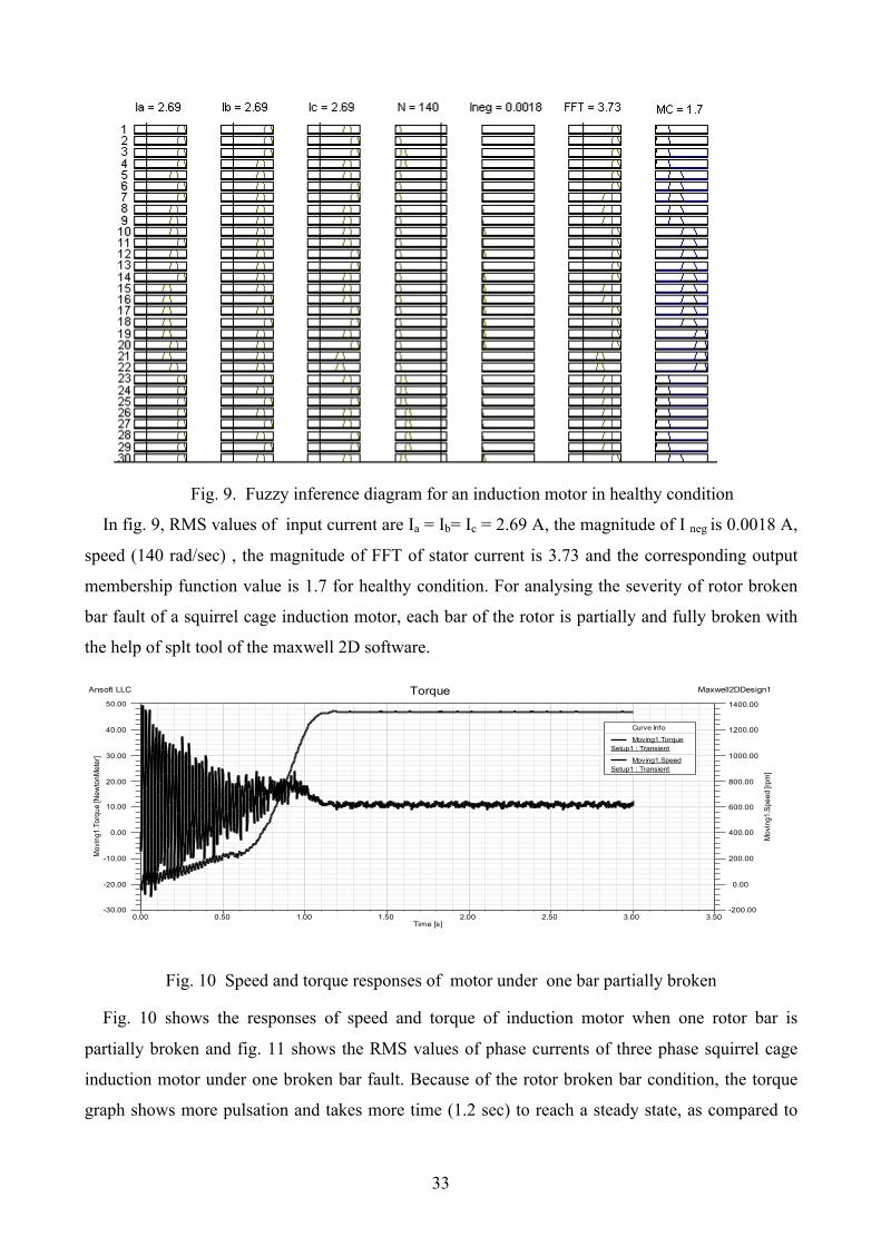
Fig. 8. The negative sequence current and magnitude of FFT under healthy condition
33
Fig. 9. Fuzzy inference diagram for an induction motor in healthy condition
In fig. 9, RMS values of input current are Ia = Ib= Ic = 2.69 A, the magnitude of I neg is 0.0018 A,
speed (140 rad/sec) , the magnitude of FFT of stator current is 3.73 and the corresponding output
membership function value is 1.7 for healthy condition. For analysing the severity of rotor broken
bar fault of a squirrel cage induction motor, each bar of the rotor is partially and fully broken with
the help of splt tool of the maxwell 2D software.
0.00 0.50 1.00 1.50 2.00 2.50 3.00 3.50Time [s]
-30.00
-20.00
-10.00
0.00
10.00
20.00
30.00
40.00
50.00
Mov
ing1
.Tor
que
[New
tonM
eter
]
-200.00
0.00
200.00
400.00
600.00
800.00
1000.00
1200.00
1400.00
Mov
ing1
.Spe
ed [r
pm]
Ansoft LLC Maxwell2DDesign1Torque
Curve Info
Moving1.TorqueSetup1 : Transient
Moving1.SpeedSetup1 : Transient
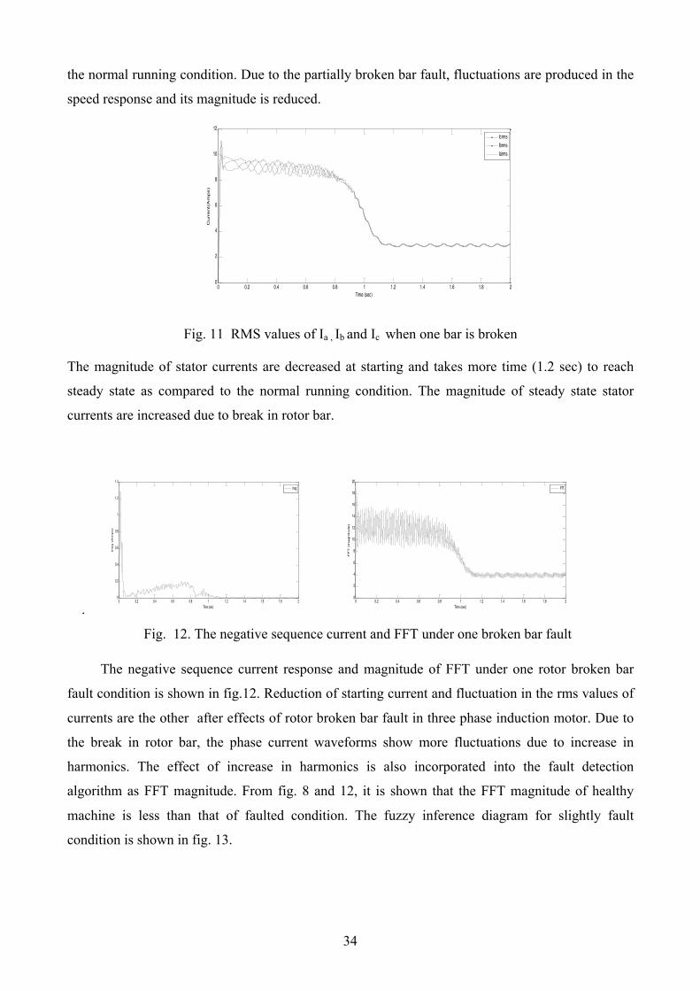
Fig. 10 Speed and torque responses of motor under one bar partially broken
Fig. 10 shows the responses of speed and torque of induction motor when one rotor bar is
partially broken and fig. 11 shows the RMS values of phase currents of three phase squirrel cage
induction motor under one broken bar fault. Because of the rotor broken bar condition, the torque
graph shows more pulsation and takes more time (1.2 sec) to reach a steady state, as compared to
34
the normal running condition. Due to the partially broken bar fault, fluctuations are produced in the
speed response and its magnitude is reduced.
0 0.2 0.4 0.6 0.8 1 1.2 1.4 1.6 1.8 20
2
4
6
8
10
12
Time (sec)
Curr
ent(
Am
ps)
IcrmsIbrmsIarms
Fig. 11 RMS values of Ia , Ib and Ic when one bar is broken
The magnitude of stator currents are decreased at starting and takes more time (1.2 sec) to reach
steady state as compared to the normal running condition. The magnitude of steady state stator
currents are increased due to break in rotor bar.
. 0 0.2 0.4 0.6 0.8 1 1.2 1.4 1.6 1.8 2
0
0.2
0.4
0.6
0.8
1
1.2
1.4
Time (sec)
Ineg (
Am
ps)
Ineg
0 0.2 0.4 0.6 0.8 1 1.2 1.4 1.6 1.8 20
2
4
6
8
10
12
14
16
18
20
Time (sec)
FF
T (
magnitude)
FfT
Fig. 12. The negative sequence current and FFT under one broken bar fault
The negative sequence current response and magnitude of FFT under one rotor broken bar
fault condition is shown in fig.12. Reduction of starting current and fluctuation in the rms values of
currents are the other after effects of rotor broken bar fault in three phase induction motor. Due to
the break in rotor bar, the phase current waveforms show more fluctuations due to increase in
harmonics. The effect of increase in harmonics is also incorporated into the fault detection
algorithm as FFT magnitude. From fig. 8 and 12, it is shown that the FFT magnitude of healthy
machine is less than that of faulted condition. The fuzzy inference diagram for slightly fault
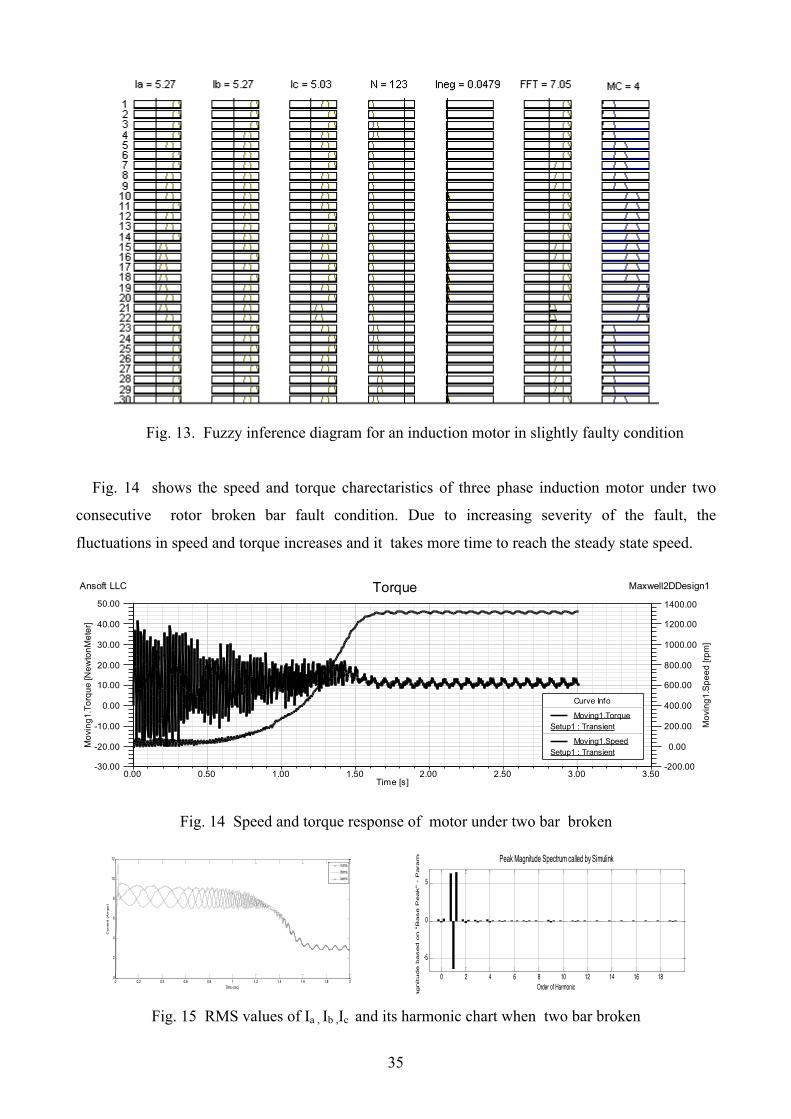
condition is shown in fig. 13.
35
Fig. 13. Fuzzy inference diagram for an induction motor in slightly faulty condition
Fig. 14 shows the speed and torque charectaristics of three phase induction motor under two
consecutive rotor broken bar fault condition. Due to increasing severity of the fault, the
fluctuations in speed and torque increases and it takes more time to reach the steady state speed.
0.00 0.50 1.00 1.50 2.00 2.50 3.00 3.50Time [s]
-30.00
-20.00
-10.00
0.00
10.00
20.00
30.00
40.00
50.00
Mov
ing1
.Tor
que
[New
tonM
eter
]
-200.00
0.00
200.00
400.00
600.00
800.00
1000.00
1200.00
1400.00
Mov
ing1
.Spe
ed [r
pm]
Ansoft LLC Maxwell2DDesign1Torque
Curve Info
Moving1.TorqueSetup1 : Transient
Moving1.SpeedSetup1 : Transient
Fig. 14 Speed and torque response of motor under two bar broken
0 0.2 0.4 0.6 0.8 1 1.2 1.4 1.6 1.8 20
2
4
6
8
10
12
Time (sec)
Curr
ent
(Am
ps)
IcrmsIbrmsIarms
0 2 4 6 8 10 12 14 16 18
-5
0
5
Order of Harmonic
Magnitude b
ased o
n "
Base P
eak"
- P
ara
mete
r
Peak Magnitude Spectrum called by Simulink
Fig. 15 RMS values of Ia , Ib ,Ic and its harmonic chart when two bar broken
36
Fig.15. shows the variation of RMS values of phase current and its harmonic chart of a three
phase induction motor under two consecutive numbers of rotor bar are in broken condition. The
harmonic chart is also called peak magnitude spectrum. It indicates the variation of order of
harmonics with its peak magnitude. When a broken bar fault is occurred in the machine, the
fluctuations of current and thus harmonics is also increased due to increase in severity of the fault.
Harmonic chart of three phase induction motor on two consecutive rotor bar broken fault shows
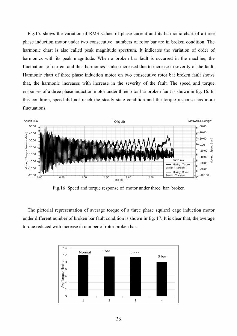
that, the harmonic increases with increase in the severity of the fault. The speed and torque
responses of a three phase induction motor under three rotor bar broken fault is shown in fig. 16. In
this condition, speed did not reach the steady state condition and the torque response has more
fluctuations.
0.00 0.50 1.00 1.50 2.00 2.50 3.00 3.50Time [s]
-20.00
-10.00
0.00
10.00
20.00
30.00
40.00
50.00
Mov
ing1
.Tor
que
[New
tonM
eter
]
-100.00
-80.00
-60.00
-40.00
-20.00
0.00
20.00
40.00
60.00
Mov
ing1
.Spe
ed [r
pm]
Ansoft LLC Maxwell2DDesign1Torque
Curve Info
Moving1.TorqueSetup1 : Transient
Moving1.SpeedSetup1 : Transient
Fig.16 Speed and torque response of motor under three bar broken
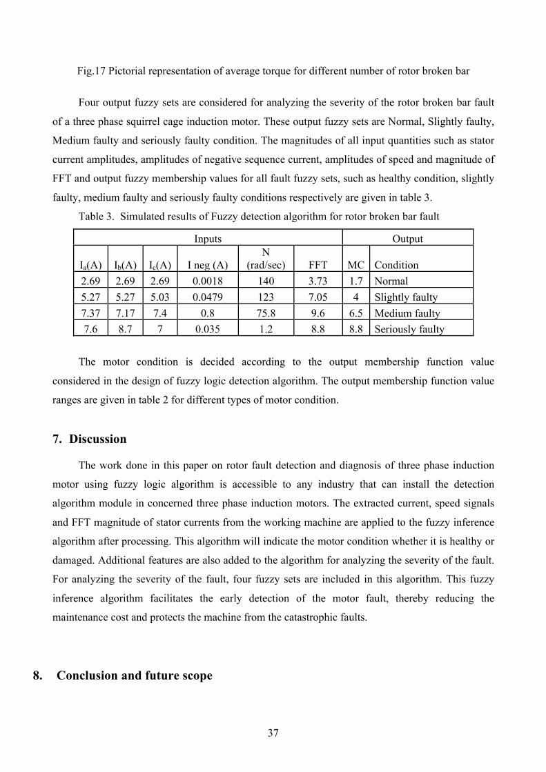
The pictorial representation of average torque of a three phase squirrel cage induction motor
under different number of broken bar fault condition is shown in fig. 17. It is clear that, the average
torque reduced with increase in number of rotor broken bar.
Normal
37
Fig.17 Pictorial representation of average torque for different number of rotor broken bar
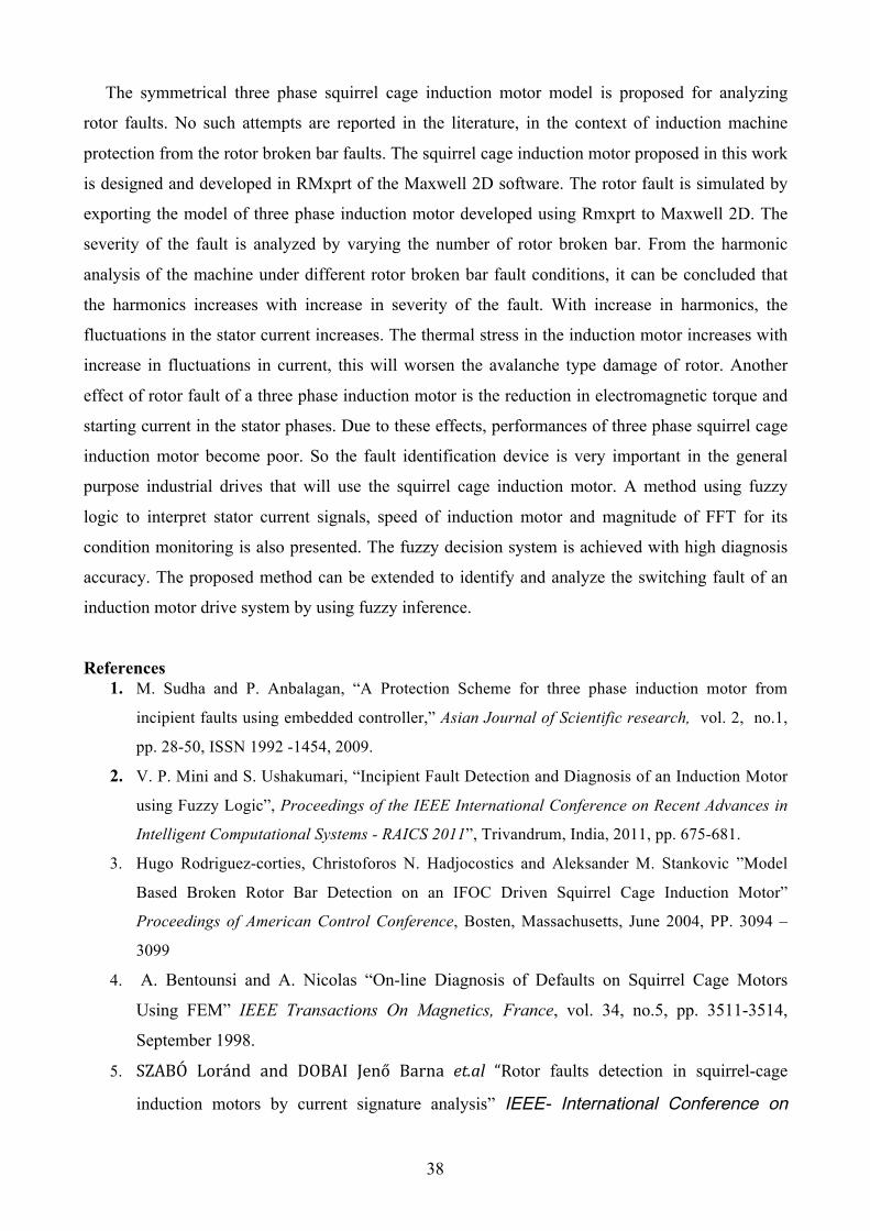
Four output fuzzy sets are considered for analyzing the severity of the rotor broken bar fault
of a three phase squirrel cage induction motor. These output fuzzy sets are Normal, Slightly faulty,
Medium faulty and seriously faulty condition. The magnitudes of all input quantities such as stator
current amplitudes, amplitudes of negative sequence current, amplitudes of speed and magnitude of
FFT and output fuzzy membership values for all fault fuzzy sets, such as healthy condition, slightly
faulty, medium faulty and seriously faulty conditions respectively are given in table 3.
Table 3. Simulated results of Fuzzy detection algorithm for rotor broken bar fault
Inputs Output
Ia(A) Ib(A) Ic(A) I neg (A) N
(rad/sec) FFT MC Condition 2.69 2.69 2.69 0.0018 140 3.73 1.7 Normal 5.27 5.27 5.03 0.0479 123 7.05 4 Slightly faulty 7.37 7.17 7.4 0.8 75.8 9.6 6.5 Medium faulty 7.6 8.7 7 0.035 1.2 8.8 8.8 Seriously faulty
The motor condition is decided according to the output membership function value
considered in the design of fuzzy logic detection algorithm. The output membership function value
ranges are given in table 2 for different types of motor condition.
7. Discussion
The work done in this paper on rotor fault detection and diagnosis of three phase induction
motor using fuzzy logic algorithm is accessible to any industry that can install the detection
algorithm module in concerned three phase induction motors. The extracted current, speed signals
and FFT magnitude of stator currents from the working machine are applied to the fuzzy inference
algorithm after processing. This algorithm will indicate the motor condition whether it is healthy or
damaged. Additional features are also added to the algorithm for analyzing the severity of the fault.
For analyzing the severity of the fault, four fuzzy sets are included in this algorithm. This fuzzy
inference algorithm facilitates the early detection of the motor fault, thereby reducing the
maintenance cost and protects the machine from the catastrophic faults.
8. Conclusion and future scope
38
The symmetrical three phase squirrel cage induction motor model is proposed for analyzing
rotor faults. No such attempts are reported in the literature, in the context of induction machine
protection from the rotor broken bar faults. The squirrel cage induction motor proposed in this work
is designed and developed in RMxprt of the Maxwell 2D software. The rotor fault is simulated by
exporting the model of three phase induction motor developed using Rmxprt to Maxwell 2D. The
severity of the fault is analyzed by varying the number of rotor broken bar. From the harmonic
analysis of the machine under different rotor broken bar fault conditions, it can be concluded that
the harmonics increases with increase in severity of the fault. With increase in harmonics, the
fluctuations in the stator current increases. The thermal stress in the induction motor increases with
increase in fluctuations in current, this will worsen the avalanche type damage of rotor. Another
effect of rotor fault of a three phase induction motor is the reduction in electromagnetic torque and
starting current in the stator phases. Due to these effects, performances of three phase squirrel cage
induction motor become poor. So the fault identification device is very important in the general
purpose industrial drives that will use the squirrel cage induction motor. A method using fuzzy
logic to interpret stator current signals, speed of induction motor and magnitude of FFT for its
condition monitoring is also presented. The fuzzy decision system is achieved with high diagnosis
accuracy. The proposed method can be extended to identify and analyze the switching fault of an
induction motor drive system by using fuzzy inference.
References 1. M. Sudha and P. Anbalagan, “A Protection Scheme for three phase induction motor from
incipient faults using embedded controller,” Asian Journal of Scientific research, vol. 2, no.1,
pp. 28-50, ISSN 1992 -1454, 2009.
2. V. P. Mini and S. Ushakumari, “Incipient Fault Detection and Diagnosis of an Induction Motor
using Fuzzy Logic”, Proceedings of the IEEE International Conference on Recent Advances in
Intelligent Computational Systems - RAICS 2011”, Trivandrum, India, 2011, pp. 675-681.
3. Hugo Rodriguez-corties, Christoforos N. Hadjocostics and Aleksander M. Stankovic ”Model
Based Broken Rotor Bar Detection on an IFOC Driven Squirrel Cage Induction Motor”
Proceedings of American Control Conference, Bosten, Massachusetts, June 2004, PP. 3094 –
3099
4. A. Bentounsi and A. Nicolas “On-line Diagnosis of Defaults on Squirrel Cage Motors
Using FEM” IEEE Transactions On Magnetics, France, vol. 34, no.5, pp. 3511-3514,
September 1998.
5. SZABÓ Loránd and DOBAI Jenő Barna et.al “Rotor faults detection in squirrel-cage
induction motors by current signature analysis” IEEE- International Conference on
39
Automation, Quality and Testing, Robotics, May 13 – 15, 2004, Cluj-Napoca,
Romania, pp. 1-6.
6. Zexiang Cai1, Aiyun Gao 1, and Jiandon.g Jiang1 “Modelling for Interior Faults of
Induction Motors and Its Simulation on EMTDC” Proceedings of the International
Conference on Power Systems Transients – IPST 2003 in New Orleans, USA, pp. 1-5.
7. Hayri Arabacı and Osman Bilgin “Neural Network Classification and Diagnosis of
Broken Rotor Bar Faults by Means of Short Time Fourier Transform” Proceedings
of the International Multi Conference of Engineers and Computer Scientists 2009,
Vol. 1, IMECS 2009, March 18 - 20, 2009, Hong Kong.
8. Christian Kral, Rudolf S. Wieser, Franz Pirker and Matthias Schagginger “Sequences of
Field-Oriented Control for the Detection of Faulty Rotor Bars in Induction Machines—The
Vienna Monitoring Method” IEEE Transactions On Industrial Electronics, vol. 47, no. 5,
October 2000, pp. 1042 – 1050.
9. Carlo Concari and Giovanni Franceschini, et.al. “Differential Diagnosis Based on
Multivariable Monitoring to Assess Induction Machine Rotor Conditions”, IEEE
Transactions On Industrial Electronics, vol. 55, no. 12, December 2008, pp. 4156-4166.
10. V. P. Mini and S. Ushakumari, “Rotor Fault Analysis of an Induction Motor Using FEM”
Proceedings of the IEEE International Conference on Power, Control and Embedded
Systems, December 2012, pp. 179-185.
11. Aderiano M. da Silva and Richard J. Povinelli et.al. “Induction Machine Broken Bar and
Stator Short-Circuit Fault Diagnostics Based on Three Phase Stator Current Envelopes”
IEEE Transactions on Industrial Electronics 2008, vol. 55. pp. 1310-1318.
12. Jarmo Lehtonen and Heikki N. Koivo, “Fault Diagnosis of Induction Motors with
Dynamical Neural Networks” Systems, Man and Cybernetics, Proceedings of the IEEE
International Conference , 2005, vol. 3, pp. 2979-2984.
13. Hugo Rodriguez-Cortes, Christofores N. Hadijicostics and Aleksander M. Stankovic
“Model-Based Broken Rotor Bar Detection on an IFOC Driven Squirrel Cage Induction
Motor” Proceedings of the American Control Conference Boston, Massachusetts June 30 –
July 2 , 2004, pp. 3094-3099.
14. Ali Ebadi, Mohammad Mirzaie and Sayyed “Employing Finite Element Method to
Analyze Performance of Three-Phase Squirrel Cage Induction Motor under Voltage
Harmonics”, Research Journal of Applied Sciences, Engineering and Technology 3(10): pp.
1209-1213, 2011.
40
15. P. Lombard, G. Meunier, "A general method for electric and magnetic coupled problem in
2D magneto dynamic domain", IEEE Transactions on Magnetics, vol. 28, no. 2, March 92,
pp. 1291-1294.
16. V. P. Mini and S. Ushakumari, “Electrical Fault Detection and Diagnosis of Induction
Motor using Fuzzy Logic” AMSE International Journal on modeling, measurement and
Simulation (Accepted for publication) 2012.
17. Lasurt, A. F. Stronach and J. Penman, "A fuzzy logic approach to the interpretation of
higher order spectra applied to fault diagnosis in electrical machines," Proceedings of 19th
International Conference of the North American Fuzzy Information Processing Society,
2000, pp.158-162.
18. M. E. H. Benbouzid and H. Nejjari, “A simple fuzzy logic approach for induction motors
stator condition monitoring,” Proceedings of IEEE International Electric Machines and
Drives Conference, 2001, pp. 634-639.
19. V. P. Mini, Sivakottiah and S. Ushakumari, “Fault Detection and Diagnosis an Induction
Motor using Fuzzy Logic,” Proceedings of the IEEE Region 8 International Conference on
Computational Technologies in Electrical and Electronics Engineering (SIBIRCON), pp.
459- 464, Irkutsk Listvyanka, Russia, July 2010.
20. Subhasis Nandi and Hamid A. Toliyat “Condition Monitoring and Fault Diagnosis of
Electrical Machines _ A Review”, Electric Machines & Power Electronics Laboratory
Department of Electrical Engineering, Texas A&M University College Station, 1999, pp.
197 -200.
21. A.K. Sawhney “A course in Electrical Machine Design”, book published by Khanna publishers, 1990.
Appendix A: Motor Parameters Horse Power: 3.7 kW, Line Voltage: 415 V, No. of Poles: 4, Rated speed: 1500 rpm / 50Hz,
Nomenclature D Stator core diameter Zss Stator Conductors per slot L Length of Induction motor Cs Coil Span Pφ Total Magnetic loading Do Outside diameter of the stator core Bavg Specific Magnetic Loading Dr Rotor Diameter Ac Specific Electric Loading lg Gap length Kw Winding Factor ms Number of Phases Q input kVA Ss Stator Slots Τ Pole Pitch Sr Rotor Slots Ts Stator turns per phase dcs Stator Core Depth